modeling and performance analysis of the main mac and phy
TRANSCRIPT
Modeling and Performance Analysis of the MainMAC and PHY Features of the 802.11ac Standard:
A-MPDU Aggregation vs Spatial MultiplexingMohand Yazid and Adlen Ksentini
Abstract—The Very High Throughput (VHT) supplied by theIEEE 802.11ac standard is the outcome of several amendments in-corporated at its both Medium Access Control (MAC) and PHYsi-cal (PHY) layers. In particular, the Aggregate-MAC Protocol DataUnit (A-MPDU) frame aggregation allows, at the MAC level, in-creasing the amount of data to be transmitted and the spatial mul-tiplexing technique serves at the PHY level to accelerate the rate atwhich such data are forwarded. Therefore, the goals we are seek-ing to achieve in this paper are, on one hand, to demonstrate thatA-MPDU aggregation and spatial multiplexing may, respectively,lead to a decrease in throughput and an increase in overhead, andon the other hand, to highlight that A-MPDU aggregation and spa-tial multiplexing have mutual needs that could mutually satisfyoperational challenges. For this purpose, we model the 802.11acstation enabling A-MPDU aggregation and spatial multiplexing,and we compute the throughput and the overhead of the 802.11acnetwork. After that, we run Monte Carlo simulations for validat-ing the accuracy of the mathematical model, and we calculate 95%confidence intervals to establish credibility to the simulation re-sults.
Index Terms—VHT IEEE 802.11ac, A-MPDU aggregation, spa-tial multiplexing, modeling, performance analysis, simulation andvalidation.
NOMENCLATURE
Acronyms
The acronyms used throughout the paper are summarizedhere. The meaning of an acronym is usually indicated once,upon first occurrence, in this paper.
A-MPDU Aggregate-MAC Protocol Data Unit.ACK ACKnowledgment.BEB Binary Exponential Backoff.BER Bit Error Rate.BPSK Binary Phase Shift Keying.CRC Cyclic Redundancy Check.
M. Yazid is with the LaMOS Research Unit, Faculty of Exact Sciences, Uni-versity of Bejaia, 06000 Bejaia, Algeria (e-mail:,[email protected]).
A. Ksentini is with the EURECOM, Campus SophiaTech, 06410 Biot, France(e-mail:,[email protected]).
CSI Channel State Information.CSMA/CA Carrier Sense Multiple Access/Collision
Avoidance.CTI Cross Talk Interference.DCF Distributed Coordination Function.IFSs Inter-Frame Spaces.L-LTF Legacy-Long Training Field.L-SIG Legacy-Signaling field.L-STF Legacy-Short Training Field.MAC Medium Access Control.MCS Modulation and Coding rates Schemes.MIMO Multiple-Input Multiple-Out.MPDU MAC Protocol Data Unit.MT Mobile Terminal.PHY PHYsical.PPDU PHY Protocol Data Unit.PSDU PHY Service Data Unit.RTS/CTS Request To Send/Clear To Send.VHT Very High Throughput.VHT-LTF VHT-Long Training Field.VHT-SIG-A VHT-Signaling part A.VHT-SIG-B VHT-Signaling part B.VHT-STF VHT-Short Training Field.WLANs Wireless Local Area Networks.256-QAM 256-Quadrature Amplitude Modulation.
Notations
In this paper notations are generally confined to the sectionin which they are used. The main notations are given here.
AMPDU Size of an A-MPDU frame.BA Size of a Block ACK.DIFS Duration of distributed inter-frame space.DLT Size of the MPDU delimiter in an A-MPDU.E[HT ] Mean channel holding time.E[payload] Average amount of payload bits successfully
transmitted on the transmission channel.FCS Size of the frame check sequence of a MPDU.HM AC Size of the MAC header of a MPDU.HDR Size of management information of a MPDU in
an A-MPDU.HTR HDR transmission rate per spatial stream.

m Maximum backoff stage.MSDU Size of a MAC service data unit.MTR MSDU transmission rate per spatial stream.n Number of stations in the network.Nmpdu Number of MPDUs contained in an A-MPDU.Nss Number of spatial streams.OH Overhead of the 802.11ac network.PB Probability that the channel is busy.PC Collision probability of an A-MPDU.PSU C Probability that a 802.11ac station wins the trans-
mission channel.PT R Probability that there is at least one station trans-
mitting data.PAD Size of the padding in an A-MPDU.SIFS Duration of short inter-frame space.TBA Transmission time of a BA.TSU C Sensing time of a successful transmission.TU N S Sensing time of an unsuccessful transmission.TH Throughput of the 802.11ac network.Tmpdu Transmission time of a MPDU on a single spatial
stream.Tampdu Transmission time of an A-MPDU of Nmpdu
MPDUs on Nss spatial streams.Tpayload Transmission time of payload bits of an A-MPDU
frame.TS Duration of a time slot.TSampdu Transmission time, in number of time slots, of an
A-MPDU.TP H Y Transmission time of the PHY header.W0 Minimum contention window.Wi Contention window size at the ith transmission
attempt.Wm Maximum contention window.δ Signal propagation time.τ Transmission probability of an A-MPDU.
I. INTRODUCTION
THE advent of the new IEEE 802.11ac standard has com-pletely revolutionized the world of Wireless Local Area
Networks (WLANs) by providing new WiFi controllers labeled“ac” whose performances are almost similar to their Ether-net counterparts in the wired conventional networks. Indeed,with these new wireless cards, the transmission rate has takena historical jump from 600 Mbps in IEEE 802.11n standard to7000 Mbps; that is why we are talking about Very High Through-put (VHT) 802.11ac. This has prompted the development anddeployment of multimedia and real-time applications that arethroughput-hungry and requiring low latency. Accordingly, thedaily use of WLANs has become easier and especially morecomfortable.
For achieving a VHT in a WLAN network, several mech-anisms, methods and techniques have been introduced eitherat MAC or PHY layer of the IEEE 802.11ac standard [1]–[4].
We particularly mention two basic and mandatory characteris-tics that a 802.11ac station can handle locally for improvingits throughput. The first characteristic is about the formation oflong frames capable of reaching 1048575 bytes by using theAggregate-MAC Protocol Data Unit (A-MPDU) frame aggre-gation mechanism of the MAC layer. The second characteris-tic is regarding the use of multiple radio antennas, where it ispossible to simultaneously transmit up to eight spatial streamsby employing the spatial multiplexing technique of the PHYlayer.
At the MAC level, the A-MPDU frame aggregation involvesforming very large frames, which should in principle increasethe throughput. However, in the event of unsuccessful trans-mission (collision), which is a frequent phenomenon in 802.11networks, the larger the size of the A-MPDU frame, the higherthe time of unsuccessful transmission; which will dramaticallylower the throughput. At the PHY level, the role of the spatialmultiplexing is to accelerate data transmission speed. Neverthe-less, such acceleration concerns only the MAC frame and notthe information (such as: headers, acknowledgments, etc.) andtime delays (such as: inter-frame spaces, backoff time, etc.) formanaging the transmission of the latter, known as: overhead.Consequently, the greater the number of streams to be multi-plexed, the lower the channel efficiency is.
The main contributions of the present work are: (i) to showthe two issues of decreasing the throughput and increasing theoverhead resulting respectively from A-MPDU aggregation andspatial multiplexing; (ii) to highlight that a cross-layer commu-nication between the A-MPDU frame aggregation mechanismand the spatial multiplexing technique is needed, so that eachmechanism could benefit from the advantages of the other. Thatis, to allow using a very large frames at the MAC layer, it is nec-essary to ensure that a minimum number of radio antennas isavailable at the PHY level aiming at increasing the throughput.Furthermore, we demonstrate that an optimal MAC frame sizeexist, which allows maximizing the channel usage when usingthe spatial multiplexing technique.
To achieve the above objectives, we are opting for stochasticmathematical modeling in order to propose a new mathematicalmodel based on a Markov chain reproducing the functioning ofa 802.11ac station with A-MPDU aggregation and spatial mul-tiplexing. The purpose of the mathematical model is to computethe throughput and the overhead of the 802.11ac network. Fur-thermore, we will conduct Monte-Carlo simulations for validat-ing the accuracy of our model. We will also calculate 95% con-fidence intervals to give more credibility to simulation results.
The remainder of this paper is organized as follows. InSections II and III, we will respectively present the operatingprinciple and the work done in the field of A-MPDU aggrega-tion and spatial multiplexing. The mathematical modeling andperformance analysis of the 802.11ac network will be respec-tively provided in Section IV and V. The accuracy of our modelwill be discussed in Section VI. Finally, we will conclude thepaper in Section VII.

Fig. 1. A-MPDU frame aggregation.
II. BACKGROUND
This section is devoted to the presentation of two basic char-acteristics of the 802.11ac standard allowing to increase thewireless network throughput up to 7 Gbits/s; namely, frame ag-gregation of the MAC layer and spatial multiplexing of the PHYlayer. At the end of this section, we will also present the frameformat of the 802.11ac standard.
A. A-MPDU Frame Aggregation
At the MAC layer, the 802.11ac standard intends to use dif-ferent frame aggregation schemes. More precisely, it suggestsmandatory use of frame aggregation via an A-MPDU, which wasintroduced in 802.11n [5]. A-MPDUs are improved in 802.11acby expanding their length, thereby packing multiple MPDUswithin the same PPDU (PHY Protocol Data Unit); which inturn enhances throughput and MAC efficiency [6].
The principle of A-MPDU aggregation is to join severalMPDU subframes with an individual PHY header. Neverthe-less, all the MPDUs within an A-MPDU must be transmittedto the same receiver address. Moreover, the number of MPDUsto be aggregated relies on the number of frames already in thetransmission queue, i.e., there is no waiting/holding time to con-stitute an A-MPDU [5]. The maximum size that an A-MPDUmay obtain, i.e., the maximum size of the PSDU (PHY ServiceData Unit) that can be received is 1048575 bytes [7]. In addi-tion, aggregate exchange sequences are enabled with a protocolthat acknowledges multiple MPDUs with only one Block ACK(ACKnowledgment).
The fundamental structure of the A-MPDU aggregation ispresented in Figure 1. A set of of fields, called MPDU delimiterare introduced before each MPDU and padding bits varied from0 to 3 bytes are inserted at the queue. The basic functioningof the MPDU delimiter is to specify the MPDU position andsize within the A-MPDU frame. The padding bytes are insertedso that each MPDU is a multiple of four bytes in size, whichmay assist subframe delineation at the receiver. In simple terms,the MPDU delimiter and padding bytes establish the structureof the A-MPDU frame. After the A-MPDU is received, a de-
Fig. 2. An example illustrating the spatial multiplexing.
aggregation process starts. Firstly, it checks the MPDU delimiterfor any errors on the basis of the CRC (Cyclic RedundancyCheck) value. If it is correct, the MPDU is extracted, and itcontinues with the next subframe until it reaches the end of thePSDU. In the opposite case, it checks every four bytes untilit locates a valid MPDU delimiter or the end of the PSDU.The delimiter signature has a single pattern to help the de-aggregation process while scanning the MPDU delimiter.
B. Spatial Multiplexing Technique
The most used MIMO (Multiple-Input Multiple-Out) tech-nique, especially with products respecting the 802.11ac stan-dard is the spatial multiplexing. The data to be transmitted issplit into N streams, and each stream is transmitted over a sep-arate antenna [8]. This will have taken N times less time thatit would have taken if only one antenna was used to transmitthe data from beginning to end. The throughput is therefore N
times higher. When these N streams reach the receiver antennas,provided they have distinctive spatial signatures, the receiver isthen able to distinguish them, to receive them successfully andthus reconstruct the original data. The spatial multiplexing istherefore more efficient when there are many obstacles and re-flections, notably inside buildings.
The principle of spatial multiplexing is as follows. Let usconsider the example shown in Figure 2, which consists of onesender and one receiver, each have two antennas in the contextof the spatial multiplexing. The Figure 2 shows the real situationand its representation in the context of the spatial multiplexing.The signal transmitted by the antenna 1 of the sender is denotedas E1. It is captured by the antenna 1 of the receiver after havingundergone an attenuation denoted as A11. In the same way, thesignal E2 transmitted by the antenna 2 of the sender is capturedby the antenna 1 of the receiver after having undergone anattenuation denoted as A21. The signal captured by the antenna1 of the receiver, denoted as R1, is defined by Equation (1).Similarly, the signal captured by the antenna 2 of the receiveris given by Equation (2). The receiver having received R1 andR2, if it could also estimate the value of different attenuations

Fig. 3. 802.11ac PPDU format.
TABLE IFIELDS OF THE 802.11AC PPDU
(A11, A12, A21, and A22), then it can retrieve E1 and E2. This isa resolution of a system of two equations with two unknowns.
R1 = E1 × A11 + E2 × A21. (1)
R2 = E1 × A12 + E2 × A22. (2)
The number of streams simultaneously transmitted is con-strained by the minimum number of antennas of the receiver orthe sender. Indeed, the sender obviously cannot transmit moresimultaneous streams than the number of antennas it uses, andthe receiver is not be able to decode more streams than thenumber of antennas it uses; because the system of equationswould have fewer equations than unknowns, which is impossi-ble to resolve. The 802.11ac standard foresees at most 8 spatialstreams, which assumes that the sender and receiver have atmost 8 antennas and are compatible with this mode [9].
C. 802.11ac PPDU Format
During a transmission, a PSDU is processed and appendedto the PHY preamble to create the PPDU. At the receiver, thePHY preamble is processed to help in the detection, demodula-tion and delivery of the PSDU [10]. Figure 3 shows the 802.11acPPDU format. The fields of the 802.11ac PPDU format are sum-marized in Table I [11]. L-STF, L-LTF and L-SIG fields are allfor the purpose of compatibility with legacy 802.11a/n devices.VHT-SIG-A is important for multi-user MIMO to inform theparticipating stations of the parameters of the directional por-tion of the frame. VHT-STF is a training field whose primarypurpose is for MIMO data power computation. VHT-LTFs areused to periodically compute the CSI (Channel State Informa-tion), through a channel sounding protocol [12], needed forMIMO transmission. Finally, VHT-SIG-B includes informationregarding MCS (Modulation and Coding rates Schemes) and peruser data field lengths. The detailed description of the 802.11acPHY preamble is provided in [12].
III. RELATED WORK
In this section, we give a literature review of the main re-search that has been done on the fundamental characteristics ofthe 802.11ac standard, including: A-MPDU frame aggregationat the MAC layer and spatial multiplexing technique (or sim-ply multi-antenna transmission) at the PHY layer. Indeed, wedistinguish in this area of research three different kinds of pa-per: the research focusing on spatial multiplexing technique, theresearch that optimises the operation of the A-MPDU frame ag-gregation, and finally, the research that considers both A-MPDUaggregation and spatial multiplexing.
In the context of spatial multiplexing technique, Redieteabet al. in [13] proposed an approach based on the modeling of bothMAC and PHY related aspects to make a comparison betweensingle-user MIMO and multi-user MIMO. The authors high-lighted that it is important to consider the CTI (Cross Talk Inter-ference) when assessing the performance of multi-user MIMOtransmission schemes. Indeed, multi-user MIMO transmissioncan sometimes have less throughput gain and be much less stablethan single-user MIMO. Oh et al. in [14] implemented a IEEE802.11ac channel sounding simulator and presented the relativeresults including signal representation, frequency response andconstellation. The authors demonstrated that, the CSI is stronglyneeded for enhancing the 802.11ac spatial multiplexing capac-ity. Firstly, the CSI should be well estimated by the receivingstation. Secondly, the estimated CSI has to be transmitted to thetransmitting station with a minimum time delay. Zubow et al. in[15] demonstrated that the down-link of 802.11ac-based wire-less networks with unequal network load can be considerablyimproved when performing a combination of two physical layerMIMO techniques, namely: multi-user MIMO and interferencenulling. The former mitigates interference within a cell, whereasthe latter reduces inter-cell interference. Kampeas et al. in [16]proposed and evaluated two distributed opportunistic user selec-tion algorithms for down-link multi-user MIMO, which selecta group of users to transmit concurrently, in a single iteration,without coordinating between the users and with very limitedCSI exchange between the users and the access point. The pro-posed algorithms not only select users with preferable channelconditions for transmission, but also minimize the interferenceamong the selected users.
Regarding A-MPDU frame aggregation, Bellalta et al. in [17]proposed and analyzed a method for performing frame aggre-gation. The obtained results show that, if the number of activestations is excessively high, the heterogeneity of destinationsin the frames contained in the queue makes it hard to reap thefull benefits of the frame aggregation. According to the au-thors, this issue may be mitigated by increasing the queue size,which enhances the opportunity of scheduling a considerablenumber of frames at each transmission; thereby providing im-proved system throughput to the detriment of a higher delay.Nomura et al. in [18] proposed a frame aggregation methodthat uses the receiving MT (Mobile Terminal) selection provid-ing higher priority to MTs with higher throughput in the next

transmission, while minimizing signaling overhead. The trans-mission performance and its fairness between MTs have beenanalyzed by means of system-level simulation. From the pre-sented results, the proposed method significantly improves bothperformances, compared with the traditional frame aggregationmethods.
Finally, the most critical studies addressing both A-MPDUaggregation and spatial multiplexing are: (i) Cha et al. in [19],who addressed a trade-off problem between multi-user MIMOof the 802.11ac standard; (ii) multi-user frame aggregation pro-posed by Singh in [20]. The authors drew two conclusions fromtheir study: if each user’s encoded data stream has a similarlength, the multi-user MIMO gives better average throughputthan the multi-user frame aggregation; otherwise, the frame ag-gregation performs better than multi-user MIMO regarding theaverage throughput. Chung et al. in [21] introduced an A-MPDUframe aggregation scheme using fragmented MPDUs with aVHT compressed Block ACK. The authors showed throughcomputer simulation that the use of fragmented MPDUs withinthe A-MPDU frame alleviates the waste of spatial medium re-sources in terms of meaningless A-MPDU paddings. Conse-quently, the proposed method reaches a multi-user throughputimprovement, over 28% at low data rates and up to 3% at highdata rates. Abdallah et al. in [22] implemented a throughput-maximization framework for the joint adaptation of data rate,MIMO mode and frame aggregation configuration. The authorsprovided approximate throughput expressions for different datarates and MIMO modes by using approximate expressions forBER (Bit Error Rate). They further underlined that, for eachBER value, there is an optimal frame size, which maximizesthroughput. However, the proposed framework is based onlyon point-to-point transmission, i.e., it does not consider theimpact of collisions on the achieved throughput. Khan et al.in [23] demonstrated via computer simulation and theoreti-cal analysis that the choice of a particular modulation andcoding scheme, number of spatial streams, and channel sizecan strongly compromise the 802.11ac throughput. Although802.11ac increases throughput several fold due to high-ordermodulation scheme, more bandwidth and spatial streams, theperformance can degrade substantially in an error-prone chan-nel. However, the conducted analysis has completely ignoredthe effect of large sizes of the A-MPDU frame on the 802.11acperformance.
Whilst much research has been devoted to studying and en-hancing both A-MPDU frame aggregation and spatial multi-plexing technique, no studies have focused specifically on thefollowing issues:
� The impact of the A-MPDU frame size on the decrease ofthe 802.11ac throughput;
� The impact of the number of spatial streams on the increaseof channel overhead.
The core contribution of our research work lies in proposinga new mathematical model based on a Markov chain, whichmodels the behavior of a 802.11ac station taking into account
both A-MPDU frame aggregation and spatial multiplexing tech-nique. The mathematical model will be then used to highlightthe following phenomena:
� Increasing the size of the A-MPDU frame cannot alwaysincrease the throughput because of collisions;
� Increasing the number of spatial streams leads to increaseof the throughput, but it causes an inefficient use of channeldue to overheads;
� Finally, we show in what way both A-MPDU frame aggre-gation and spatial multiplexing technique can be used sothat they could mutually satisfy operational challenges.
IV. MODELING 802.11AC WITH A-MPDU AGGREGATION
AND SPATIAL MULTIPLEXING
In this section, we propose a new three-dimensional discretetime Markov chain that models the functioning of a 802.11acstation enabling essentially the following two mechanisms,namely: the A-MPDU frame aggregation mechanism at theMAC layer and the spatial multiplexing mechanism at the PHYlayer. Resolving the equations of the stationary probabilitiesof this Markov chain will allow us to determine the A-MPDUtransmission probability τ of a 802.11ac station. This proba-bility will then be used for developing mathematical models,in order to compute the throughput and the overhead of the802.11ac network.
A. Hypothesis of the 802.11ac Mathematical Model
In what follows, we provide a detailed listing of all of thebasic underlying hypothesis for the purposes of modeling the802.11ac network with A-MPDU aggregation and spatial mul-tiplexing. Tables II and III respectively define all the parametersand the basic probabilities necessary for modeling the 802.11acnetwork.
1) The network is composed by a constant number of802.11ac stations, where their transmission queues alwayscontain MPDUs to be transmitted on the network.
2) Each 802.11ac station considers a single traffic class withthe same contention parameters, namely: the inter-framespaces and the contention window. This means that the802.11ac stations perform the Distributed CoordinationFunction (DCF) [10], which allows a single traffic classto gain access to the channel when its backoff time counteris zero for transmitting one A-MPDU frame.
3) The transmission channel is ideal, which means that col-lisions are the only reason of data loss in the network.
4) At the MAC level, all stations in the network implementthe A-MPDU frame aggregation mechanism. Thus, priorto any transmission, A-MPDU frames of the same size areformed from simple MPDUs.
5) At the PHY level, all stations in the network enable thespatial multiplexing mechanism with the same numberof spatial streams for sending and receiving A-MPDUframes.

TABLE IIPARAMETERS OF THE 802.11AC MATHEMATICAL MODEL
TABLE IIIPROBABILITIES OF THE 802.11AC MATHEMATICAL MODEL
6) The 802.11ac stations access the transmission chan-nel by following the rules of Carrier Sense MultipleAccess/Collision Avoidance (CSMA/CA) protocol [24],i.e., without using the Request To Send/Clear To Send(RTS/CTS) exchange sequence. This enables a clear eval-uation of the role played by A-MPDU aggregation andspatial multiplexing in optimizing the 802.11ac networkperformance.
7) The collision probability of an A-MPDU frame is constantfor all 802.11ac stations, and it is also independent of thenumber of transmission failures.
B. Transmission Probability τ of an A-MPDU Frame
For estimating the transmission probability τ that a 802.11acstation transmits an A-MPDU frame in an arbitrary time slot,we propose to model the operation of a single 802.11ac stationby a Markov chain. Thereafter, this probability will be neededto compute the throughput and the overhead of the 802.11acnetwork.
Let X(t) be the stochastic process modeling the status s
(s ∈ {B, T}) of a 802.11ac station at a given time slot t. In-deed, a 802.11ac station may find itself in two different situa-tions, namely: the status noted B which means that the 802.11acstation is in the process of decrementing its backoff time counter,
and the status noted T which means that the 802.11ac station isin the process of transmitting its A-MPDU frame.
Let Y (t) be the stochastic process modeling, at a given timeslot t, either the backoff stage i (in the case of the status B),or the ith retransmission attempt of an A-MPDU frame (in thecase of the status T ). The values of i vary from 0 to m.
Let Z(t) be the stochastic process modeling, at a given timeslot t, either the remaining backoff time j to decrement (in thecase of the status B), or the elapsed time k of transmission of anA-MPDU frame (in the case of the status T ). The possible valuesof j and k vary from 1 to Wi − 1 and from 0 to TSampdu − 1,respectively.
For each 802.11ac station:� The size of the contention window Wi at the backoff stage
i is determined using Equation (3). Indeed, Wi follows abinary exponential algorithm.
Wi = 2i × W0. (3)
� The transmission time TSampdu, in number of time slots,of an A-MPDU frame is determined using Equation (4).It is obtained by dividing the transmission time Tampdu,in number of microseconds, of an A-MPDU frame by theduration of a time slot TS, which means the minimum du-ration of detecting a transmission over the radio channel.This division operation is required, because the stochasticprocess Z(t) (previously defined) evolves following in-stants of time expressed in time slots. This requirementoriginally is imposed by the backoff time counter [10],which is expressed in terms of time slots.
TSampdu =Tampdu
TS. (4)
� The transmission time Tampdu of an A-MPDU frame isdetermined using Equation (5). It is computed by multiply-ing the transmission time Tmpdu of a MPDU (on a singlespatial stream) by the number Nmpdu of MPDUs aggre-gated into the A-MPDU frame, then divided by the numberNss of spatial streams. This is how A-MPDU frame ag-gregation and spatial multiplexing mechanisms have beentaken into account in developing our mathematical model.
Tampdu =Nmpdu × Tmpdu
Nss. (5)
� The transmission time Tmpdu of a MPDU on a single spa-tial stream is determined using Equation (6). It is calculatedby dividing the size HDR of management information ofa MPDU and the size MSDU of a MAC service dataunit (data payload) by their respective transmission rates,namely: the transmission rate HTR of management infor-mation and the transmission rate MTR of data payload.Indeed, management information and data payload are usu-ally transmitted using different modulation techniques.
Tmpdu =HDR
HTR+
MSDU
MTR. (6)

Fig. 4. Markov chain model of a 802.11ac station enabling A-MPDU frame aggregation and spatial multiplexing mechanisms.
� The size HDR of management information of a MPDU inan A-MPDU frame is determined using the Equation (7). Itis obtained by adding the size HM AC of the MAC header,the size FCS of the frame check sequence, the size DLT
of the MPDU delimiter and the size PAD of the padding.
HDR = HM AC + FCS + DLT + PAD. (7)
The three-dimensional process {X(t), Y (t), Z(t)} can bemodeled by the discrete-time Markov chain represented inFigure 4, upon adoption of the well-known hypothesis ofBianchi’s model [25]. This hypothesis is defined as follows:at each transmission attempt, and regardless of the number ofretransmissions, each packet collides with constant and inde-pendent probability.
The mathematical model, for modeling the first versions (a,b and g) of the IEEE 802.11 standard, introduced by Bianchi in[25] can always be expanded for modeling the IEEE 802.11acamendment. We argue this by the fact that the basic functioningof 802.11ac is still conform to the original IEEE 802.11 standard[24]. Indeed, the process of competition between the stations(allowing a station to gain access to the channel) and the errorrecovery mechanism (allowing a station to retransmit lost data)have remained unchanged, namely: the Carrier Sense MultipleAccess/Collision Avoidance (CSMA/CA) protocol, the BinaryExponential Backoff (BEB) algorithm, the Inter-Frame Spaces(IFSs) delays, etc.
Our mathematical model differs from that of the Bianchi’smodel mainly in the transmitting phase. In the Bianchi’s model,
only one MPDU (a simple frame) can be transmitted at onceon one spatial stream. But with our model, a series (Nmpdu)of MPDUs (an A-MPDU frame) can be transmitted at onceon multiple (Nss) spatial steams. In the Bianchi’s model, thetransmission is simply modeled by the states where the Backoffcounter is zero. While, in our model, the transmission is modeledby the states whose first value is T. The transmission time is nottaken into account in the Bianchi’s model. In our model, thetransmission time is calculated by parameter TSampdu, whichis given by Equation (4).
In the following, we list all non-zero transition probabilitiesand their meaning of the proposed Markov chain:
� The transition probability P{B, i, j/B, i, j + 1} from thestate (B, i, j + 1) to the state (B, i, j) for i ∈ [0,m] andj ∈ [1,Wi − 2] is given by the Equation (8). It models thedecrementing of the backoff time counter of a 802.11acstation.
P{B, i, j/B, i, j + 1} = 1 − PB . (8)
� The transition probability P{T, i, 0/B, i, 1} from the state(B, i, 1) to the state (T, i, 0) for i ∈ [0,m] is given byEquation (9). It models the decrementing of the last timeslot of the backoff time counter of a 802.11ac station beforestarting the transmission of its A-MPDU frame.
P{T, i, 0/B, i, 1} = 1 − PB . (9)
� The transition probability P{B, i, j/B, i, j} from the state(B, i, j) to the same state (B, i, j) for i ∈ [0,m] and

j ∈ [1,Wi − 1] is given by Equation (10). It models thefreeze of the decrementing of the backoff time counter ofa 802.11ac station because of detecting a busy channel.
P{B, i, j/B, i, j} = PB . (10)
� The transition probability P{T, i, k + 1/T, i, k} from thestate (T, i, k) to the state (T, i, k + 1) for i ∈ [0,m] andk ∈ [0, TSampdu − 2] is given by Equation (11). It mod-els the transmission of an A-MPDU frame of a 802.11acstation.
P{T, i, k + 1/T, i, k} = 1. (11)
� The transition probability P{B, 0, j/T, i, TSampdu−1}from the state (T, i, TSampdu − 1) to the state (B, 0, j)for i ∈ [0,m] and j ∈ [1,W0 − 1] is given by Equation(12). It models the selection of a new backoff time counterin the contention window W0 for transmitting a new A-MPDU frame.
P{B, 0, j/T, i, TSampdu − 1} =1 − Pc
W0. (12)
� The transition probability P{T, 0, 0/T, i, TSampdu − 1}from the state (T, i, TSampdu − 1) to the state (T, 0, 0)for i ∈ [0,m] is given by Equation (13). It models thetransmission of a new A-MPDU frame with a zero backofftime counter.
P{T, 0, 0/T, i, TSampdu − 1} =1 − Pc
W0. (13)
� The transition probability P{B, i,j/T,i−1,TSampdu−1}from the state (T, i − 1, TSampdu − 1) to the state(B, i, j) for i ∈ [1,m] and j ∈ [1,Wi − 1] is givenby Equation (14). It models the selection of a newbackoff time counter in the contention window Wi forretransmitting a lost A-MPDU frame.
P{B, i, j/T, i − 1, TSampdu − 1} =Pc
Wi. (14)
� The transition probability P{T, i,0/T,i−1,TSampdu−1}from the state (T, i − 1, TSampdu − 1) to the state(T, i, 0) for i ∈ [1,m] is given by Equation (15). It modelsthe ith retransmission with zero backoff time counter of alost A-MPDU frame.
P{T, i, 0/T, i − 1, TSampdu − 1} =Pc
Wi. (15)
� The transition probability P{B,m, j/T,m,
TSampdu − 1} from the state (T,m, TSampdu − 1) tothe state (B,m, j) for j ∈ [1,Wm − 1] is given by Equa-tion (16). It models the selection of a new backoff timecounter in the contention window Wm for retransmittinga lost A-MPDU frame.
P{B,m, j/T,m, TSampdu − 1} =Pc
Wm. (16)
� The transition probability P{T,m, 0/T,m,TSampdu − 1} from the state (T,m, TSampdu − 1) to
the state (T,m, 0) is given by the Equation (17). It modelsthe selection of a zero backoff time counter in the backoffstage m for retransmitting a lost A-MPDU frame.
P{T,m, 0/T,m, TSampdu − 1} =Pc
Wm. (17)
The proposed Markov chain model represents in a compre-hensive manner the decrementing of the backoff time counter(across the states (B, i, j) for i ∈ [0,m] and j ∈ [1,Wi − 1])and the transmission of the A-MPDU frame (across the states(T, i, k) for i ∈ [0,m] and k ∈ [0, TSampdu − 1]). Therefore,the 802.11ac station randomly selects a backoff time counterwhich is decremented as long as the transmission channel is idle.When the last time slot of the backoff time counter (which is rep-resented by the state (B, i, 1) for i ∈ [0,m]) is decremented, the802.11ac station stats the transmission of its A-MPDU frame.At the end of the last time slot of the A-MPDU transmissiontime (which is represented by the state (T, i, TSampdu − 1) fori ∈ [0,m]), two events (in terms of probabilities) are possibleregardless of the minimum sensing time of a collision:
1) Successful transmission modeled by the probability 1 −PC . The 802.11ac station will therefore choose a newbackoff time counter in the initial contention window (W0)to transmit a new A-MPDU frame.
2) Unsuccessful transmission modeled by the probabilityPC . The 802.11ac station will first double its current con-tention window (Wi) while the maximum backoff stage(m) is not reached, then it chooses a new backoff counterto retransmit the lost A-MPDU frame.
We will now calculate for each state (s, i, h) of the pro-posed Markov chain its stationary probability πs,i,h , where:s ∈ {B, T}, i ∈ [0,m], h ∈ {j, k}, j ∈ [1,Wi − 1] and k ∈[0, TSampdu − 1]. The mathematical formula of πs,i,h is givenby Equation (18). It represents the probability of being in thestate (s, i, h) at infinity, i.e., when the system will have suffi-ciently functioned. In fact, we will give more attention to thesestationary probabilities in the remainder of this section, in orderto determine the transmission probability τ .
πs,i,h = limt→∞P{X(t) = s, Y (t) = i, Z(t) = h} (18)
In order to find the stationary distribution of our Markovchain, we apply the well-known Balance Equation [26] givenby Equation (19), where: S is the state space of the Markovchain, πi is the stationary probability of being in the state i, andpij is the transition probability from the state i to the state j.The Balance Equation has the following interpretation: it saysthat in the Markov chain, the flow from the state i to the state jis equal to that from the state j to the state i. For more detailsabout the Balance Equation, please refer to [26].
πi × pij = πj × pji , ∀i, j ∈ S. (19)
After applying the Balance Equation on our Markov chain,we have obtained the following stationary probabilities:
� The stationary probability πB,i,j of being in the state(B, i, j) for i ∈ [0,m − 1] and j ∈ [1,Wi − 1] is given

by Equation (20).
πB,i,j =Wi − j
Wi× P i
C
1 − PB× πT ,0,0. (20)
� The stationary probability πB,m,j of being in the state(B,m, j) for j ∈ [1,Wm − 1] is given by Equation (21).
πB,m,j =Wm − j
Wm× Pm
C
(1 − PB )(1 − PC )× πT ,0,0.
(21)� The stationary probability πT ,i,k of being in the state
(T, i, k) for i ∈ [0,m − 1] and k ∈ [0, TSampdu − 1] isgiven by Equation (22).
πT ,i,k = πT ,i,0 = P iC × πT ,0,0. (22)
� The stationary probability πT ,m,k of being in the state(T,m, k) for k ∈ [0, TSampdu − 1] is given by Equation(23).
πT ,m,k = πT ,m,0 =Pm
C
1 − PC× πT ,0,0. (23)
According to the equations (20), (21), (22) and (23), the sta-tionary probabilities πs,i,h are expressed as a function that de-pendents on the following probabilities: the stationary probabil-ity πT ,0,0, the collision probability PC of an A-MPDU frame,and the probability PB that the channel is sensed busy by a802.11ac station. πT ,0,0 can then be found by imposing the nor-malization condition on our Markov chain. It is obtained asfollows:
1 =m∑
i=0
Wi −1∑
j=1
πB,i,j +m∑
i=0
T Sampdu−1∑
k=0
πT ,i,k ,
= πT ,0,0 ×
⎡
⎢⎣W0 × (1 − PC − PC × (2PC )m )
+(1 − 2PC )
× (2 × TSampdu × (1 − PB ) − 1)
⎤
⎥⎦
2 × (1 − PC ) × (1 − 2PC ) × (1 − PB ). (24)
Hence, we have:
πT ,0,0 =2 × (1 − PC ) × (1 − 2PC ) × (1 − PB )⎡
⎢⎣W0 × (1 − PC − PC × (2PC )m )+(1 − 2PC )
× (2 × TSampdu × (1 − PB ) − 1)
⎤
⎥⎦
. (25)
Now, the transmission probability τ of an A-MPDU framecan be expressed as the sum of stationary probabilities πT ,i,k
of transmission states (T, i, k), where i ∈ [0,m] and k ∈[0, TSampdu − 1]. It is obtained as follows:
τ =m∑
i=0
T Sampdu−1∑
k=0
πT ,i,k =TSampdu
1 − PC· πT ,0,0,
=2 × TSampdu × (1 − 2PC ) × (1 − PB )⎡
⎢⎣W0 × (1 − PC − PC × (2PC )m )
+(1 − 2PC )
× (2 × TSampdu × (1 − PB ) − 1)
⎤
⎥⎦
. (26)
The transmission probability τ of an A-MPDU frame, in turn,is based on the following probabilities:
� PC (the collision probability of an A-MPDU frame): theprobability that an A-MPDU frame of a 802.11ac station islost because of a collision at a given time slot, is expressedas the probability that at least one other station amongn − 1 stations of the 802.11ac network transmits. It isobtained as follows:
PC = 1 − (1 − τ)n−1. (27)
� PB (the probability that the channel is busy): the prob-ability that the transmission channel is sensed busy by a802.11ac station at a given time slot, is expressed as theprobability that at least one other station among n − 1 sta-tions of the 802.11ac network transmits. It is obtained asfollows:
PB = PC = 1 − (1 − τ)n−1. (28)
The resolution of the equations (26), (27) and (28), whichtogether form a system of nonlinear equations, by means ofnumerical methods, allows us to obtain the numerical values ofthe transition probabilities and stationary probabilities.
C. Throughput (TH)
The throughput (TH) that may be achieved in a 802.11acnetwork, is determined from the various events happeningon the transmission channel during an arbitrary time slot. Inthe following, we provide the basic parameters required fordeveloping TH:
� Let PT R be the probability that there is at least one stationtransmitting data at a given time slot. Since n stationscontend on the channel, and each transmits with probabilityτ , PT R is given as follows:
PT R = 1 − (1 − τ)n . (29)
� Let PSU C be the probability that a 802.11ac station winsthe transmission channel at a given time slot. PSU C isexpressed by the fact that exactly one 802.11ac stationtransmits on the transmission channel. This probability isalso conditioned by the fact that there is at least one stationtransmitting on channel. It is given as follows:
PSU C =nτ(1 − τ)n−1
1 − (1 − τ)n. (30)
� Let TSU C be the sensing time of a successful transmis-sion of an A-MPDU frame of a 802.11ac station on thetransmission channel. TSU C is given a follows:
TSU C = TP H Y + Tampdu + SIFS + TBA
+ DIFS + 2 × δ. (31)
� Let TU N S be the sensing time of an unsuccessful trans-mission of an A-MPDU frame of a 802.11ac station on thetransmission channel. TU N S is given a follows:
TU N S = TP H Y + Tampdu + δ + DIFS. (32)

Fig. 5. A schematic depiction of transmission channel state changes, duringan arbitrary time slot.
� Tampdu, TP H Y and TBA , are respectively determined bythe Equations (5), (33) and (34).
TP H Y = 36 μs + 4 μs × Nss. (33)
TBA =BA
HTR. (34)
To determine TH , let us analyze the different events whichcan happen in a randomly chosen time slot (these events areillustrated in Fig. 5):
� With the probability (1 − PT R ), the transmission channelis idle (PT R is given by Equation (29)). The time dura-tion of this event is TS, and the amount of payload bitssuccessfully transmitted during this event is equal to 0.
� With the probability PT R × PSU C , the transmission chan-nel contains a successful transmission (PSU C is given byEquation (30)). The time duration of this event is TSU C
(TSU C is given by the Equation (31)), and the amount ofpayload bits successfully transmitted during this event isequal to Nmpdu × MSDU .
� With the probability PT R × (1 − PSU C ), the transmissionchannel contains an unsuccessful transmission. The timeduration of this event is TU N S (TU N S is given by Equa-tion (32)), and the amount of payload bits successfullytransmitted during this event is equal to 0.
Let E[HT ] denotes the mean channel holding time. It de-pends on the events illustrated in Figure 5, namely: idle chan-nel, successful transmission, and unsuccessful transmission. Itis obtained as follows:
E[HT ] = (1 − PT R ) × TS + PT R × PSU C × TSU C
+ PT R × (1 − PSU C ) × TU N S . (35)
Let E[payload] denotes the average amount of payload bitssuccessfully transmitted on the transmission channel in a ran-domly chosen time slot. It is obtained as follows:
E[payload] = PT R × PSU C × Nmpdu × MSDU. (36)
Finally, the throughput (TH) of the 802.11ac network isobtained as the ratio of average amount of payload bits success-
TABLE IVVALUES OF THE 802.11AC PHY AND MAC PARAMETERS
fully transmitted on the transmission channel to mean channelholding time E[HT ]. It is given as follows:
TH =E[payload]
E[HT ]. (37)
D. Overhead (OH)
The overhead OH of the 802.11ac network can be expressedas the fraction of time that the transmission channel is employedfor handling the successful transmission of payload bits of an A-MPDU frame; it means the fraction of time that the transmissionchannel is not used to successfully transmit the payload bits ofan A-MPDU frame. OH is determined using Equation (38),where: Tpayload denotes the transmission time of payload bitsof an A-MPDU frame. E[HT ] and Tpayload are respectivelygiven by Equations (35) and (39).
OH =E[HT ] − Tpayload
E[HT ](38)
Tpayload =Nmpdu × M SDU
M T R
Nss(39)
V. NUMERICAL RESULTS AND PERFORMANCE ANALYSIS
In this section, the aim is to examine the numerical resultsobtained after the implementation (under Matlab) of the math-ematical model presented in the previous section. These resultsare generated using various criteria, including: the size of theA-MPDU frame, the number of spatial streams and the numberof stations in the network. To generate the figures below, wehave used the values presented in Table IV, which are obtainedfrom the IEEE 802.11ac standard [10]. In particular, the valuesof MTR and HTR are calculated by using 160 MHz channelsin the 5 GHz band, and applying respectively the followingmodulation and coding rates schemes: 256-Quadrature Ampli-tude Modulation (256-QAM) and Binary Phase Shift Keying(BPSK). The ultimate objectives of this section are organizedas follows:
� Firstly, we will show that the size of the A-MPDU frame,which may extend to 1048575 bytes, has a negative impacton the achieved throughput in a 802.11ac network. In-deed, when the A-MPDU frame reaches a certain size, thethroughput of the 802.11ac network declines as A-MPDUframe size increases.

Fig. 6. Throughput variation according to the A-MPDU frame size over onespatial stream.
� Secondly, we will show that the use of multiple spatialstreams (up to 8) causes an increase in the overhead ofthe 802.11ac network. As the number of spatial streamsincreases, the overhead of the 802.11ac network becomesincreasingly greater.
� Thirdly, we will show that the use of multiple spatialstreams provides a solution to the problem of decreasein the throughput of the 802.11ac network resulting fromthe size of the A-MPDU frame. Indeed, for each number ofspatial streams, there is a maximum size of the A-MPDUframe that maximises the throughput of the 802.11ac net-work.
� Finally, we will show that the use of the A-MPDU ag-gregation in turn can lower the overhead of the 802.11acnetwork caused by the spatial multiplexing. In fact, foreach size of A-MPDU frame, there is a maximum num-ber of spatial streams that minimises the overhead of the802.11ac network.
In Figure 6, we study the variation of the achieved throughputin a midsize 802.11ac network (16 stations) according to thenumber of MPDUs contained in an A-MPDU frame for differentsizes of MSDU (payload bits of a MPDU), namely: 2000 bytes(small-sized MSDU), 5000 bytes (medium-sized MSDU) and8000 bytes (large-sized MSDU). To obtain the results of thisfigure, we have considered one spatial stream at the PHY layer.This result will allow us to focus on how A-MPDU aggregationcontributes at the MAC layer to the enhancement of the 802.11acthroughput. The Figure 6 shows that 802.11ac stations, whichare not equipped with multiple radio antennas (i.e., those whichcannot perform spatial multiplexing) will not get the benefitsof A-MPDU aggregation, even though the maximum rate of780 Mbps at which payload bits are transmitted is used. In fact,upwards of a certain size of A-MPDU frame (which is relativelysmall compared to the maximum size of the A-MPDU frame),the larger the A-MPDU frame size, the smaller the 802.11acthroughput. We argue this by the fact that the collision time ofan A-MPDU frame increases with the increase of its size; andsince the collision is a frequent phenomena in a 802.11 network,this has a heavy impact on the achieved throughput in a 802.11acnetwork.
Fig. 7. Throughput variation according to the network size with different sizesof the A-MPDU frame over one spatial stream.
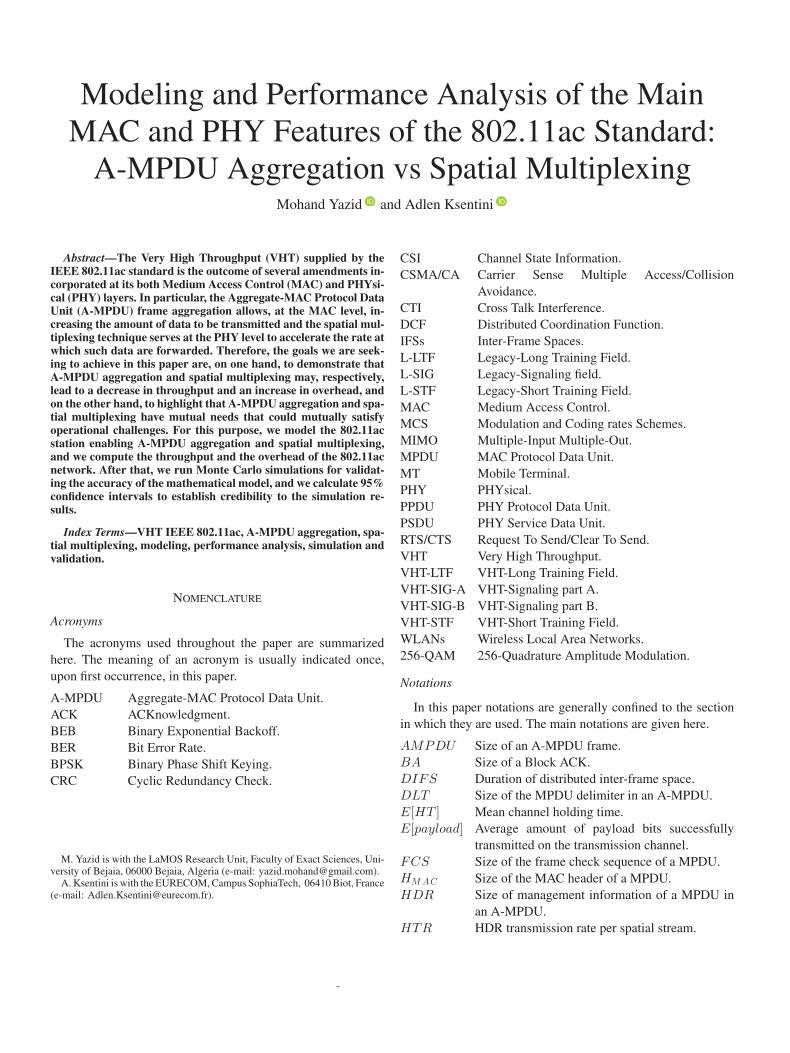
Fig. 8. Overhead variation according to the number of spatial streams with asingle MPDU in the A-MPDU frame.
In Figure 7, we study the variation of the throughput over onespatial stream according to the number of stations in the networkfor different sizes of the A-MPDU frame. Obviously, we remarkthat the more number of 802.11ac stations in the network, themore collision phenomenon is intensified. Thus, the A-MPDUaggregation is less efficient when considering improving thethroughput in a 802.11ac network.
In Figure 8, we analyze the overhead of the 802.11ac networkaccording to the number of spatial streams enabled at the PHYlayer. At the MAC layer, we have considered simple MPDUframes (i.e., without A-MPDU aggregation) of different sizesso that we can clearly demonstrate the negative effect of spa-tial multiplexing on 802.11ac network. The Figure 8 shows thatwhen 802.11ac stations do not have multiple frames (MPDUs)to be aggregated, enabling multiple spatial steams only increasesthe network overhead. As shown in this figure, as more spatialstreams are enabled, the network overhead grows, i.e., the band-width is becoming increasingly underutilized. This phenomenais even more critical when the size of data to be sent is too small.This may be explained by the fact that the use of multiple spa-tial streams accelerates only the transmission of data, while theother parameters (including: headers, inter-frame spaces and ac-knowledgments) remain as they are. This is why, the overhead ofthe 802.11ac network increases with the increase of the numberof spatial streams.
In Figure 9, we analyze the variation of the overhead ofthe 802.11ac network according to the number of stations for
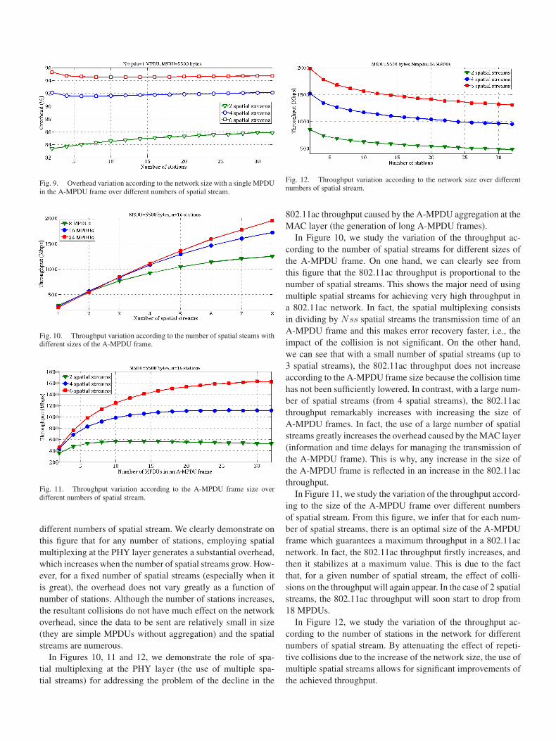
Fig. 9. Overhead variation according to the network size with a single MPDUin the A-MPDU frame over different numbers of spatial stream.
Fig. 10. Throughput variation according to the number of spatial steams withdifferent sizes of the A-MPDU frame.
Fig. 11. Throughput variation according to the A-MPDU frame size overdifferent numbers of spatial stream.
different numbers of spatial stream. We clearly demonstrate onthis figure that for any number of stations, employing spatialmultiplexing at the PHY layer generates a substantial overhead,which increases when the number of spatial streams grow. How-ever, for a fixed number of spatial streams (especially when itis great), the overhead does not vary greatly as a function ofnumber of stations. Although the number of stations increases,the resultant collisions do not have much effect on the networkoverhead, since the data to be sent are relatively small in size(they are simple MPDUs without aggregation) and the spatialstreams are numerous.
In Figures 10, 11 and 12, we demonstrate the role of spa-tial multiplexing at the PHY layer (the use of multiple spa-tial streams) for addressing the problem of the decline in the
Fig. 12. Throughput variation according to the network size over differentnumbers of spatial stream.
802.11ac throughput caused by the A-MPDU aggregation at theMAC layer (the generation of long A-MPDU frames).
In Figure 10, we study the variation of the throughput ac-cording to the number of spatial streams for different sizes ofthe A-MPDU frame. On one hand, we can clearly see fromthis figure that the 802.11ac throughput is proportional to thenumber of spatial streams. This shows the major need of usingmultiple spatial streams for achieving very high throughput ina 802.11ac network. In fact, the spatial multiplexing consistsin dividing by Nss spatial streams the transmission time of anA-MPDU frame and this makes error recovery faster, i.e., theimpact of the collision is not significant. On the other hand,we can see that with a small number of spatial streams (up to3 spatial streams), the 802.11ac throughput does not increaseaccording to the A-MPDU frame size because the collision timehas not been sufficiently lowered. In contrast, with a large num-ber of spatial streams (from 4 spatial streams), the 802.11acthroughput remarkably increases with increasing the size ofA-MPDU frames. In fact, the use of a large number of spatialstreams greatly increases the overhead caused by the MAC layer(information and time delays for managing the transmission ofthe A-MPDU frame). This is why, any increase in the size ofthe A-MPDU frame is reflected in an increase in the 802.11acthroughput.
In Figure 11, we study the variation of the throughput accord-ing to the size of the A-MPDU frame over different numbersof spatial stream. From this figure, we infer that for each num-ber of spatial streams, there is an optimal size of the A-MPDUframe which guarantees a maximum throughput in a 802.11acnetwork. In fact, the 802.11ac throughput firstly increases, andthen it stabilizes at a maximum value. This is due to the factthat, for a given number of spatial stream, the effect of colli-sions on the throughput will again appear. In the case of 2 spatialstreams, the 802.11ac throughput will soon start to drop from18 MPDUs.
In Figure 12, we study the variation of the throughput ac-cording to the number of stations in the network for differentnumbers of spatial stream. By attenuating the effect of repeti-tive collisions due to the increase of the network size, the use ofmultiple spatial streams allows for significant improvements ofthe achieved throughput.

Fig. 13. Overhead variation according to the A-MPDU frame size and fordifferent numbers of spatial stream.
Fig. 14. Overhead variation according to the number of spatial streams anddifferent sizes of the A-MPDU frame.
Fig. 15. Overhead variation according to the network size and different num-bers of spatial stream.
The objective of the Figures 13, 14 and 15 is to highlightthe necessity of using A-MPDU frame aggregation at the MAClayer in order to efficiently utilize the available bandwidth, i.e.,to lessen the overhead of the 802.11ac network caused by thespatial multiplexing at the PHY layer.
In Figure 13, we analyse the variation of the overhead of the802.11ac network according to the size of the A-MPDU frameover different numbers of spatial stream. As shown in this fig-ure, the overhead registered in a 802.11ac network is inverselyproportional to the size of the A-MPDU frame. Moreover, theoverhead reduction is much more pronounced when there aretoo many spatial streams. Indeed, as the size of the A-MPDUframe increases, the 802.11ac stations are spending more timetransmitting data than listening to the channel. Hence, the band-width is increasingly well utilized (i.e., the overhead is becoming
much smaller). However, we note that upwards of a certain sizeof A-MPDU frame (especially in the case when the number ofspatial streams is small), the overhead starts to increase again.This increase is due mostly to collision time which is gettingimportant since the size of the A-MPDU frame is great and thenumber of spatial streams is small.
In Figure 14, we analyze the variation of the overhead of the802.11ac network according to the number of spatial streamsfor different sizes of the A-MPDU frame. We note that for eachA-MPDU frame size, there is a maximum number of spatialstreams that minimizes the overhead of the 802.11ac network.If we use a lesser or greater number of spatial streams than isnecessary, the overhead in both cases is not minimized. Indeed,with an insufficient number of spatial streams, the overhead ismostly caused by the collision time, resulting in a degradation ofthe 802.11ac throughput (as shown in Figure 10). While with anoversupply of spatial streams, the overhead is caused by the pro-cess of accessing the network, resulting in an under-utilizationof the radio channel. That is why, the use of longer A-MPDUframes should improve the 802.11ac throughput (as shown inFigure 10). Hence, an optimal number of spatial streams thatminimizes the 802.11ac overhead relative to a size of A-MPDUframe is the minimum number of spatial streams to be used forreducing the impact of collisions on the 802.11ac throughput.Whereas, if the number of spatial streams used exceeds the opti-mal number, it is necessary to increase the size of the A-MPDUframe to bring down the MAC layer overhead, thus enhancingthe 802.11ac throughput.
In Figure 15, we analyze the variation of the overhead ofthe 802.11ac network according to the number of stations fordifferent sizes of the A-MPDU frame. The purpose of this figureis to demonstrate, for each network size, the need to combineA-MPDU frame aggregation with spatial multiplexing to reducethe network overhead. This figure indicates that the overheadincreases with the number of stations, as a result of repetitivecollisions. However, the overhead is inversely proportional toA-MPDU frame size when the latter does not exceed a certainthreshold. In this case, the collision time has a significant impacton the network overhead.
VI. SIMULATION AND MODEL VALIDATION
The ultimate goal of this section is to validate the accuracyof the proposed mathematical model and the theoretical resultsobtained. To do this, we have developed (under Matlab) a simu-lation program based on the Monte Carlo method [27]. Finally,to make the simulation results more credible, we have also cal-culated 95% confidence intervals.
In Figures 16 and 17, we respectively present a sample ofnumerical values of the throughput and the overhead aiming atcomparing the theoretical results (i.e., those generated from theproposed mathematical model) to their corresponding simula-tion results (i.e., those calculated on the basis of the Monte Carlosimulation). We can clearly observe that the theoretical resultsmatch well with the simulation results.

Fig. 16. Comparison between theoretical and simulation results of the802.11ac throughput.
Fig. 17. Comparison between theoretical and simulation results of the802.11ac overhead.
TABLE VTHEORETICAL THROUGHPUT, SIMULATION AND
CONFIDENCE INTERVALS (GBPS)
TABLE VITHEORETICAL OVERHEAD, SIMULATION AND CONFIDENCE INTERVALS (%)
To better demonstrate the matching between the theoreticaland simulation results of throughput and overhead, we haveprovided their numerical values in Tables V and VI, respectively.We can observe again that the simulation results are well-alignedwith the theoretical results.
To provide credible support to the simulation results presentedin Tables V and VI, we have calculated for each simulation result
its confidence interval. Since the simulation approach gives ap-proximate results [28] (unlike mathematical modeling approachthat provides exact results), the calculation of the confidenceintervals is mandatory in order to determine the margin of errorfor the simulation results.
Finally, based on Figures 16 and 17, and on Tables V and VI,we can say that the proposed mathematical model is validatedagainst simulation results and shows good agreement.
VII. CONCLUSIONS AND PROSPECTS
In this paper, we were interested in modeling and analyzingthe performance of innovative features of the very high through-put 802.11ac standard, including: A-MPDU frame aggregationat the MAC layer and spatial multiplexing technique at thePHY layer. We have mainly highlighted the mutual dependencybetween the A-MPDU frame aggregation and the spatial multi-plexing technique for optimizing the performance of a 802.11acnetwork. In addition, we have shown that optimal values of theA-MPDU frame size and the number of spatial streams shouldbe determined in order to effectively utilize the potential of A-MPDU aggregation and spatial multiplexing. To achieve ourgoal, we have proposed a new mathematical model based on aMarkov chain for estimating the throughput and the overheadof the 802.11ac network. The accuracy of this model has beenvalidated by conducting Monte Carlo simulations, for whichwe have attached confidence intervals. The analysis of the nu-merical results has identified two anomalies in the functioningof the 802.11ac network with regard to A-MPDU frame ag-gregation and spatial multiplexing. The first one is about thedecrease of the throughput as a result of increasing the sizeof the A-MPDU frame. The second issue is an increase of theoverhead resulting from the use of multiple spatial streams.The performance analysis has also shown that each of saidmechanisms is able to resolve the issue of the other. We haveshown on one hand that: for each number of spatial streams,there is a maximum size of A-MPDU frame that maximizesthe throughput. On the other hand, for each size of A-MPDUframe, there is a maximum number of spatial streams that min-imizes the overhead. This motivates our future work, wherewe will model this trade-off by using multi-criteria optimisa-tion techniques; having as objective to maximize the through-put, while minimizing the overhead of the 802.11ac networkbased on the size of A-MPDU frame and the number of spatialstreams.
REFERENCES
[1] M. Yazid, A. Ksentini, L. Bouallouche-Medjkoune, and D. Aıssani, “Per-formance analysis of the TXOP sharing mechanism in the VHT IEEE802.11ac WLANs,” IEEE Commun. Lett., vol. 18, no. 9, pp. 1599–1602,Sep. 2014.
[2] M. Yazid, A. Ksentini, L. Bouallouche-Medjkoune, and D. Aıssani, “En-hancement of the TXOP sharing designed for DL-MU-MIMO IEEE802.11ac WLANs,” in Proc. Wireless Commun. Netw. Conf., Mar. 2015,pp. 908–913.

[3] M. Yazid, L. Bouallouche-Medjkoune, and D. Aıssani, “Performancestudy of frame aggregation mechanisms in the new generation WiFi,”in Proc. Verification Evalu. Comput. Commun. Syst. Sep. 2016,pp. 85–92.
[4] S. Mammeri, M. Yazid, A. Ksentini, L. Bouallouche-Medjkoune, andD. Aıssani, “Performance study and enhancement of multichannel accessmethods in the future generation VHT WLAN,” Future Gen. Comput.Syst., vol. 79, pp. 543–557, 2018.
[5] D. Skordoulis, Q. Ni, H. H. Chen, A. P. Stephens, C. Liu, and A. Ja-malipour, “IEEE 802.11n MAC frame aggregation mechanisms for next-generation high-throughput WLANs,” IEEE Wireless Commun., vol. 15,no. 1, pp. 40–47, Feb. 2008.
[6] O. Bejarano, E. W. Knightly, and M. Park, “IEEE 802.11ac: From chan-nelization to multi-user MIMO,” IEEE Commun. Mag., vol. 51, no. 10,pp. 84–90, Oct. 2013.
[7] E. Charfi, L. Chaari, and L. Kamoun, “PHY/MAC enhancements and QoSmechanisms for very high throughput WLANs: A survey,” IEEE Commun.Surveys Tut., vol. 15, no. 4, pp. 1714–1735, Oct.–Dec. 2013.
[8] E. Perahia and R. Stacey, Next Generation Wireless LANs. Cambridge,U.K.: Cambridge Univ. Press, 2013.
[9] E. Perahia and R. Stacey, Next Generation Wireless LANs: 802.11n and802.11ac. Cambridge, U.K.: Cambridge Univ. Press, 2013.
[10] Wireless LAN Medium Access Control (MAC) and Physical Layer (PHY)Specifications: Enhancements for Very High Throughput for Operation inBands Below 6 GHz, IEEE 802.11ac Standard Draft 7.0, Part 11 Amend-ment 4, 2013.
[11] D. Nojima, L. Lanante, Y. Nagao, M. Kurosaki, and H. Ochi, “Perfor-mance evaluation for multi-user MIMO IEEE 802.11ac wireless LANsystem,” in Proc. 14th Int. Conf. Adv. Commun. Technol., Feb. 2012,pp. 804–808.
[12] G. Redieteab, “Cross-layer optimization for next generation Wi-Fi,” Ph.D.thesis, 2013. [Online]. Available: https://arxiv.org/abs/1301.4691
[13] G. Redieteab, L. Cariou, P. Christin, and J. F. Helard, “SU/MU-MIMOin IEEE 802.11ac: PHY+MAC performance comparison for single an-tenna stations,” in Proc. IEEE Wireless Telecommun. Symp., Apr. 2012,pp. 1–5.
[14] J. Oh, H. J. Hong, and H. D. Choi, “Performance analysis for channelsounding in IEEE 802.11ac network,” in Proc. Int. Conf. Inf. Commun.Technol. Convergence, Oct. 2015, pp. 1240–1242.
[15] A. Zubow, “Downlink MIMO in IEEE 802.11ac-based infrastructure net-works,” in Proc. Global Commun. Conf., 2015, pp. 1–7.
[16] J. Kampeas, A. Cohen, and O. Gurewitz, “Rate analysis of distributedmultiuser MIMO protocols for the 802.11ac,” in Proc. Int. Conf. Sci.Electric. Eng., Nov. 2016, pp. 1–5.
[17] B. Bellalta, J. Barcelo, D. Staehle, A. Vinel, and M. Oliver, “On the per-formance of packet aggregation in IEEE 802.11ac MU-MIMO WLANs,”IEEE Commun. Lett., vol. 16, no. 10, pp. 1588–1591, Oct. 2012.
[18] Y. Nomura, K. Mori, and H. Kobayashi, “Efficient frame aggregation withframe size adaptation for next generation MU-MIMO WLANs,” in Proc.9th Int. Conf. Next Gen. Mobile Appl., Services Technol. IEEE, Sep. 2015,pp. 288–293.
[19] J. Cha, H. Jin, B. C. Jung, and D. K. Sung, “Performance comparison ofdownlink user multiplexing schemes in IEEE 802.11ac: Multi-user MIMOvs. frame aggregation,” in Proc. Wireless Commun. Netw Conf., Apr. 2012,pp. 1514–1519.
[20] Wwise Proposal: High Throughput Extension to the 802.11 Standard,IEEE 802.11-04/886r6, 2005.
[21] C. Chung, T. Chung, B. Kang, and J. Kim, “A-MPDU using fragmentedMPDUs for IEEE 802.11ac MU-MIMO WLANs,” in Proc. TENCONIEEE Region 10 Conf. (31194). IEEE, Oct. 2013, pp. 1–4.
[22] S. Abdallah and S. D. Blostein, “Joint rate adaptation, frame aggrega-tion and MIMO mode selection for IEEE 802.11ac,” in Proc. WirelessCommun. Netw. Conf., Apr. 2016, pp. 1–6.
[23] G. Z. Khan, R. Gonzalez, E. C. Park, and X. W. Wu, “Analysis of veryhigh throughput (VHT) at MAC and PHY layers under MIMO channel inIEEE 802.11ac WLAN,” in Proc. 19th Int. Conf. Adv. Commun. Technol.IEEE, Feb. 2017, pp. 877–888.
[24] Part 11: Wireless LAN Medium Access Control (MAC) and Physical Layer(PHY) Specifications: Higher-Speed Physical Layer Extension in the 2.4GHz Band, IEEE 802.11 Standard, 1999.
[25] G. Bianchi, “Performance analysis of the IEEE 802.11 distributed coordi-nation function,” IEEE J. Sel. Areas Commun., vol. 18, no. 3, pp. 535–547,Mar. 2000.
[26] C. Gardiner, Stochastic Methods. Berlin, Germany: Springer, 2009.
[27] C. Ouanteur, D. Aıssani, L. Bouallouche-Medjkoune, M. Yazid, andH. Castel-Taleb, “Modeling and performance evaluation of the IEEE802.15.4e LLDN mechanism designed for industrial applications inWSNs,” Wireless Netw., vol. 23, no. 5, pp. 1343–1358, 2017.
[28] M. Yazid, D. Aıssani, and L. Bouallouche-Medjkoune, “Modeling andanalysis of the TXOPLimit efficiency with the packet fragmentation in anIEEE 802.11e-EDCA network under noise-related losses,” Wireless Pers.Commun., vol. 95, no. 2, pp. 1505–1530, 2017.
Mohand Yazid received the Engineer, the Magister,the Doctorate, and the HU (Habilitation Universi-taire) degrees from the University of Bejaia, Bejaia,Algeria, in 2008, 2011, and 2017, respectively, allin computer science. He was the Network Adminis-trator of CEVITAL Company for three years, wherehe undergone training on Cisco Networking (ICND1,ICND2, IUWNE, CVOICE and CWLMS). After re-ceiving the Magister degree, he has been a Teacherwith the Department of Computer Science, Univer-sity of Bejaia (teaching programming and algorith-
mic, data structures, computer networks, security of networks, modeling andsimulation of systems, and performance evaluation of networks). His researchinterests include modeling, simulation, performance evaluation, and optimiza-tion of IEEE 802.11 wireless networks and IEEE 802.15.4 wireless sensornetworks.
Adlen Ksentini received the Ph.D. degree in com-puter science from the University of Cergy-Pontoise,Cergy, France, in 2005, with a dissertation on QoSprovisioning in IEEE 802.11-based networks. From2006 to 2016, he was with the University of Rennes 1as an Assistant Professor. During this period, he was amember of the Dionysos Team with INRIA, Rennes.Since March 2016, he has been working as an As-sistant Professor with the Communication SystemsDepartment, EURECOM, Biot, France. He is also aCOMSOC Distinguished Lecturer. He has been in-
volved in several national and European projects on QoS and QoE supportin future wireless, network virtualization, cloud networking, mobile networks,and more recently on network slicing and 5G in the context of H2020 projects5G!Pagoda and 5GTransformer. He has coauthored more than 100 technicaljournal and international conference papers. He received the Best Paper Awardfrom IEEE IWCMC 2016, IEEE ICC 2012, and ACM MSWiM 2005. He hasbeen awarded the 2017 IEEE Comsoc Fred W. Ellersick (best IEEE com-munications Magazines paper). He has given several tutorials in IEEE interna-tional conferences, IEEE Globecom 2015, IEEEE CCNC 2017, IEEE ICC 2017,IEEE/IFIP IM 2017. He has been acting as the TPC Symposium Chair for IEEEICC 2016/2017, IEEE GLOBECOM 2017, IEEE Cloudnet 2017, and IEEE5G Forum 2018. He has been acting as a Guest Editor for the IEEE JOURNAL
OF SELECTED AREA ON COMMUNICATION Series on Network Softwerization,IEEE WIRELESS COMMUNICATIONS, IEEE COMMUNICATIONS MAGAZINE, andtwo issues of ComSoc MMTC Letters. He has been on the Technical ProgramCommittees of major IEEE ComSoc, ICC/GLOBECOM, ICME, WCNC, andPIMRC conferences. He is currently the Director of the IEEE ComSoc EMEAregion and the Vice-Chair of the IEEE ComSoc Technical Committee on Soft-ware (TCS).