modeling engine friction with temperature dependence …€¦ · modeling engine friction with...
TRANSCRIPT

MODELING ENGINE FRICTION WITH TEMPERATURE DEPENDENCE FOR VEHICLE THERMAL MANAGEMENT Roberto Rastelli, Xiaobing Liu BorgWarner Inc. Brad Tillock EngSim Corporation

Objective and Approach
2
Simulation
Controls
Test Results
Simulation and Development Part of Gasoline Thermal
Management Vehicle Demonstrator Objective Impact on fuel economy of several
thermal management technologies and strategies
Simulation - Test Results - Controls Co-simulation Controller in Simulink Plant model in GT-Suite

Popular Mid-size (D-Segment) base vehicle. 2L displacement I4, turbocharged CR: 9.3:1 240 HP @ 5,500 RPM (premium gas) 231 HP @ 5,500 RPM (regular gas) 270 lb-ft @ 3000 RPM Head & Block: aluminum
Engine Cooling Layout Test Platform
3

4
Dual Mode Coolant Pump
(DMCP)
Electric Coolant Control Valve
(ECCV)
Exhaust Heat Recovery System
(EHRS)
Engine Cooling Layout Advanced Thermal Components in Update Build
ADVANCED
Engine Oil Heat Exchanger (EOHX)
Transmission Oil Heat Exchanger
(TOHX) Auxiliary Loop
Control Valve(s)
STANDARD

Engine Cooling Layout Baseline
5
Head
Block
Water Pump
Thermo-stat
Cabin Heater
Radiator
Expan-sion Tank
Trans OC
Bypass
Degas Hose
Degas Hose
Turbo Stat Closed

Engine Cooling Layout Baseline
6
Head
Block
Water Pump
Thermo-stat
Cabin Heater
Radiator
Expan-sion Tank
Trans OC
Bypass
Degas Hose
Degas Hose
Turbo Stat Open

DMCP Bypass Valve
7
Engine Cooling Layout Update Build
System Layout & Valve Definition
Head
Block
DMCP Pump Inlet
Radiator
Expan-sion Tank
Degas Hose
Degas Hose
Turbo
ECCV
Trans Oil HX
IN
HTR
IN HTR
ALT
IN
HTR
Cabin Heater
EHRS Valve
EOHX Valve
Main CCV
Trans.
Trans Oil Thermostat Valve
Gas Side Bypass Valve
EHRS
Engine Oil HX
IN HTR
TOHX Valve

Six operating modes 1. Cold start (zero engine
flow, cab heater flow) 2. Engine oil warm up (flow
through engine) 3. Transmission oil warm up
(flow through TOHx) 4. Hot operation w/ stat closed
(no flow through radiator) 5. Hot operation w/ stat open
(flow through radiator) 6. Engine off – pump after-run
Hot soak operation (radiator on)
Cold soak operation (radiator off)
Engine Cooling Layout Operating Modes
8

Simulation Model and Features Integrated Model
9
Mean Value Engine Model
Vehicle Model Thermal System Model
with coolant & oil circuits Thermal Controller

Simulation Model and Features Vehicle/Transmission Model
10
Vehicle Throttle control set up to follow user
defined drive cycle Axle, vehicle body, tire rolling
resistance, aerodynamic drag, road grade
Transmission Friction losses based on input speed
and ATF temperature/pressure Gear shift schedule correlated with
vehicle data

Temperature dependent losses in the transmission. This data comes from
transmission bench tests at variable temperature.
11
Simulation Model and Features Temperature Effects - Transmission

Simulation Model and Features Engine Model
12
EHRS
Engine mean value model Details

Simulation Model and Features Engine Model – Friction Model
13
Warm FMEP map Inputs: RPM, imep
Toil
Tblk
Engine Friction model Detail

Simulation Model and Features Engine Model – Friction Model
14
Dyno testing used to determine the engine friction temperature effects
Method was to collect IMEP during warm-up in neutral IMEP above the ‘warm’ IMEP
is attributed to friction

Simulation Model and Features Engine Model – Friction Model
15
Correction function determined by: Subtract off trans spin loss Normalize by the ‘warm’ IMEP
The correction function and
curve fit are shown to the right
Different breakdowns of oil and spark base temperature were tested

Simulation Model and Features Block-Head Model
16
Engine Block Engine block modeled with
3 masses (head, inner-block, outer-block)
Thermal loading of head and inner block as a function of engine operating conditions
Flow dependent heat transfer to coolant
… to Friction Model

Simulation Model and Features Oil Thermal Model
17
Oil System Thermally loaded by
block conduction, friction, and piston heat transfer
… to Friction Model

Simulation Model and Features Integrated Model
18
Cooling System Full cooling system model Simple under-hood flow model with
radiator fan heat exchanger performance maps
based on SS test data

Simulation Results and Validation FTP Validation – Baseline
19
Simulation Dyno Test
Engine Head Metal T
Engine Oil Sump T Radiator Inlet Coolant T
Engine Outlet Coolant T

Simulation Results and Validation FTP Validation – Baseline, Adv Control
20
Base Adv. Control
Plots compare metal and oil temperatures for a baseline case and a ‘controlled’ case with zero flow strategy and oil heating.
Simulation Test

Simulation for control design and strategy optimization Manage thermal system to minimize fuel consumption Protect engine and vehicle components from thermal
damage
Thermal Controller
21
Data Acquisition
Valve actuation
Thermocouples
Fire extinguisher
Controller

Thermal Controller Initial Dyno Test Results
22
0 100 200 300 400 500 600 700 800 900 1000 1100 1200 1300 1400Time
Spee
d [km
/hr]
020406080
100120
Vehicle Speed
Pum
p Spe
ed [R
PM]
0
600
1200
1800
2400
3000
3600
4200
4800
5400
6000
Tstat
Ope
n [%
]
0102030405060708090100
Ther
mal
Mod
e
0123456
Pump SpeedFan SpeedThermostat OpeningThermal Mode
Tem
p [D
egC]
20
40
60
80
100
120
Engine Inlet Coolant TEngine Outlet Coolant TEngine Oil TEngine Outlet Coolant T - SetTransmission Oil T
From SAE 14TMSS-0093
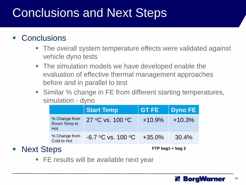
Conclusions The overall system temperature effects were validated against
vehicle dyno tests The simulation models we have developed enable the
evaluation of effective thermal management approaches before and in parallel to test
Similar % change in FE from different starting temperatures, simulation - dyno
Next Steps FE results will be available next year
Conclusions and Next Steps
23
Start Temp GT FE Dyno FE % Change from Room Temp to Hot
27 oC vs. 100 oC +10.9% +10.3%
% Change from Cold to Hot
-6.7 oC vs. 100 oC +35.0% 30.4%
FTP bag1 + bag 2

Thank You For Your Attention Questions ?
Fuel Economy Emissions Performance
Our Vision A Clean, Energy-Efficient World
Our Mission Deliver Innovative Powertrain Solutions that Improve
Fuel Economy, Emissions & Performance