modeling of timber fl oors strengthened with seismic
TRANSCRIPT

Wiadomości Konserwatorskie • Journal of Heritage Conservation • 46/2016 69
NAUKA SCIENCE
1. INTRODUCTIONTimber unidirectional fl oors, composed by fl oor-
boards orientated perpendicularly to the timber beams and connected with a couple of nails at each intersec-tion, were traditionally used for the construction of horizontal diaphragms in historic structures and still often adopted in contemporary buildings [1], [2], [3]. Nevertheless, especially in seismic area, due to the low in-plane stiffness and the frequent lack of effective connections to the masonry shearwalls [4], [5], [6], existing timber fl oors cannot assure a suitable “box” behaviour [2], [3] and were often the cause of brittle collapses, mainly due to out-of-plane failures [7], [8]. Consequently, in the last decades, several research works have been focused on the characterization of the in plane behaviour of unstrengthened timber fl oors and on the identifi cation of dry, effi cient and compatible strengthening techniques [9], [10], [11], [12], [13], [14], as well as in the improvement of fl oor-to-wall connections [3], [10], [15], [16]. In this context, the study of the infl uence of deformable fl oors on the seismic behaviour of existing masonry buildings is underway, but still deserves further investigations, both
Maria Rosa Valluzzi*, Enrico Garbin**, Claudio Modena***, Enzo Bozza****, Dario Francescato*****
Modeling of timber fl oors strengthened with seismic improvement techniques
Modelowanie stropów drewnianych wzmocnionych metodami zwiększającymi wytrzymałość sejsmiczną
Key words: timber fl oor, in-plane behaviour, FEM, connection, diagonals, seismic improvement
Słowa kluczowe: strop drewniany, praca w płaszczyźnie, MES, połączenie, przekątne, podniesienie wytrzymałości sejsmicznej
Praca dopuszczona do druku po recenzjach Article accepted for publishing after reviews
* Ass. Prof., DBC – University of Padova, Italy, [email protected]** Ph.D., DICEA – University of Padova, Italy, [email protected]*** Full Prof., DICEA – University of Padova, Italy, [email protected]**** Tech. Dir., Bozza srl, [email protected]***** P. Eng., [email protected]
Cytowanie / Citation: Valluzzi M.R., Garbin E., Modena C., Bozza E., Francescato D. Modeling of timber fl oors strengthened with seismic improvement techniques. Wiadomosci Konserwatorskie – Journal of Heritage Conservation 2016;46:69-79
Otrzymano / Received: 05.12.2015 • Zaakceptowano / Accepted: 11.02.2016 doi:10.17425/WK46TIMBER
at experimental [2], [4], [12], [14] and numerical level [11], [14], [17], [18], in order to better understand the infl uence of type, number and deformation capacity of the connections between beams and fl oorboards, and the effect of possible strengthening techniques on the mechanical performance of the timber fl oor.
Laboratory push-out tests on assemblages with various arrangements and timber-to-board connec-tions, and selected in-plane monotonic shear tests on scaled portions of timber fl oors in unstrengthened and strengthened conditions, constituted the basic data for the calibration of inelastic Finite Elements (FE) mod-els. All specimens were made of spruce wood.
Four conditions including single and double boards connected with the bearing beams of the fl oor with Ø2,75 × 60 mm nails and/or Ø6×100 mm or Ø6×120 mm screws were preliminarily examined on a total of 12 subassemblies. Calibration of load-displacement curves was performed by modeling the connections of nail and screw with the beam and the boards with non-linear elastic elements.
Then, the effect of diagonals made of wood, steel or composite materials acting as in-plane stiffen-
70 Wiadomości Konserwatorskie • Journal of Heritage Conservation • 46/2016
ing techniques on simple-boarding fl oor specimens (about 2.2 × 2.2 m2) were modelled. In particular, two unstregnthened specimens and fi ve strengthened ones subjected to monotonic shear loading, as in [14], were examined. The strengthening was made of: wooden boards 150 mm wide with thicknesses of 25 and 50 mm; 40 × 2 mm2 punched steel strip (net area of 60 mm2); 200 × 0.165 mm2 Carbon Fibre Re-inforced Polymer (CFRP) and 170 × 0.378 mm2 Steel Reinforced Polymer (SRP).
Calibrated curves on experimental push-out test results were used. The glued connections with CFRP or the SRP diagonals were assumed as perfectly effi -cient [19] and modelled without any inelastic interface behaviour between the planking and the strengthening composite materials. The screw connections of the punched steel strip were calibrated directly on the data of the tested timber fl oor.
Based of the validated models, a preliminary parametric study including the variation of the axial stiffness of a theoretical diagonal strengthening inter-vention was carried out.
The main results are discussed in the following.
2. EXPERIMENTAL TESTING
Data collection and laboratory tests were performed to defi ne the materials composing the specimens, the connections made with metal fasteners and the in-plane behaviour of the unstrengthened and reinforced timber fl oors.
2.1. Materials
The mechanical properties of the spruce wood used in the specimens were: 455 kg/m3 as volume mass, 44 N/mm2 as compressive strength, 66 N/mm2 as fl exural strength and an estimated longitudinal elastic modulus of 11000 N/mm2, as suggested in [20]. The Moisture Content (MC) of all timber components was measured according to UNI 9091 [21] after their construction and before carrying out the tests. The average MC was of 12%.
Tensile tests on the punched steel strip provided an average ultimate load of 24.51 kN, an ultimate tensile strength of 408 N/mm2 and a modulus of elasticity of 210000 N/mm2.
Properties of composites were derived from the technical datasheets: CFRP had an equivalent dry thick-ness of 0.165 mm, a tensile strength of 2500 N/ mm2
and a modulus of elasticity of 230000 N/ mm2; SRP was made with Ultra-High Tensile Strength Steel (UHTSS) and had an equivalent dry thickness of 0.378 mm, a tensile strength of 3070 N/mm2 and a modulus of elasticity of 190000 N/mm2. CFRP and SRP were glued to the fl oor specimens with epoxy resin by means the wet lay-up procedure commonly adopted for Externally Bonded Fibre Reinforced Poly-mers (EB-FRPs).
2.2. Push-out specimens
The steel connections, i.e., nails and screws, were characterized by means of push-out tests carried out according to UNI-EN 26891 [22] under loading con-trol (Fig. 1). Nails and screws were spaced according to Eurocode 5 [23]. The specimens where built with four arrangements in order to reproduce the behav-iour of the connections between the timber beams and fl oorboards used for fl oor segment specimens in unstrengthened and strengthened conditions, as in [14]. Three specimens for each condition were tested.
The push-out specimen PO.F1.M simulated the sym-metric connection made by 8+8 nails Ø2.75×60 mm between the beam 120×140 mm and the two basic boards 20 mm thick (Fig. 1a). The specimens PO.F2a.M (Fig. 1b) and PO.F2b.M (Fig. 1c) simulated the sym-metric connection made by the former 16 nails plus that given by 8 + 8 screws Ø6 × 100 mm (for PO.F2a.M) or Ø6 × 120 mm (for PO.F2b.M) connecting two extra external boards 25 or 40 mm thick, respectively. The last two subassemblies represented the connections of the strengthening confi gurations made with one thick ret-rofi tting planking or diagonal elements. The specimen PO.F3.M (Fig. 1d) simulated the symmetric connec-tion used for the application of a second strengthening planking made with boards 25 mm thick above the fi rst strengthening deck 25 mm thick.
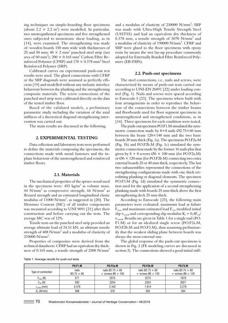
According to Eurocode [23], the following main parameters were evaluated: maximum load at failure Fmax and maximum estimated load Fest, modifi ed initial slip νi,mod and corresponding slip modulus Ks = 0,4Fest/νi,mod. Results are given in Table 1 for a single nail (PO.F1.M) or for an idealized single screw (PO.F2a.M, PO.F2b.M and PO.F3.M), thus assuming preliminar-ily that the weakest sliding plane between boards was always the most external one.
The global response of the push-out specimens is shown in Fig. 2 (FE modeling curves are discussed in section 3). The connections showed a good initial stiff-
Table 1. Average results for push-out test s
PO.F1.M PO.F2a.M PO.F2b.M PO.F3.M
Type of connection nailsØ2,75 × 60
nails Ø2.75 × 60 + screws Ø6 × 100
nails Ø2.75 × 60 + screws Ø6 × 120
nails Ø2.75 × 60 + screws Ø6 × 120
Fmax (N) 571 2075 2273 1970Fest (N) 592 2254 2324 2021
νi,mod (mm) 0.476 2.442 1.914 3.279Ks (N/mm) 588 378 503 264

Wiadomości Konserwatorskie • Journal of Heritage Conservation • 46/2016 71
ness, followed by a pseudo plastic branch, due to the yielding of the nails or screws at interfaces and/or the splitting of the boards. In the case of PO.F1.M the nail connection worked mainly under pure shear (Fig. 3a), whereas in the PO.F2a.M, PO.F2b.M and PO.F3.M, due to the presence of multiple boards, the connec-tions worked mainly under a combined shear-bending stress-state. They showed the rope-effect, which at the end caused some splitting failures of the strengthening boards (Fig. 3b, c and d).
2.3. Floor specimens
Seven fl oor specimens were tested under monot-onic shear loading with a set-up formerly implemented at the Department of Civil, Architectural and Environ-mental Engineering of the University of Padova [14], [24]. The specimen were positioned in a steel hinged quadrilateral, able to restrain out-of-plane movements and to reproduce a 2D vertical cantilever beam. The steel reaction beam, to which is fully connected the fi rst timber beam of the fl oor, was connected to the steel basement trough three load cells with mechanical slid-
ing connections, thus providing two vertical and one horizontal simple supports. The tests were performed in displacement control. Displacement transducers were used to record horizontal, vertical and diagonal relative movements (Fig. 4) [14], [24].
Two specimens, FMSB and FM, were unstrength-ened. They were representative of south-European mono-directional fl oors, composed by simple sup-ported timber beams and a transversal planking. The specimens (about 2.2 × 2.2 m2), were built with com-ponents in real size: fi ve beams 120 × 140 mm in sec-tion at 500 mm off-centre and a basic boarding 135 mm wide and 20 mm thick were used. Each fl oorboard was joined to every beam by means of 2 nails Ø2.75 × 60 mm, for a total of 32 nails per each beam, 10 nails per each fl oorboard and a total number of 160 nails per fl oor. Specimen FMSB was made with common raw-fi nished fl oorboards, whereas FM had a tongue-and groove shaped connection in the fl oorboard thickness.
Five fl oor specimens were strengthened with di-agonals made of various materials or arrangements.
Specimen FMWD(25) refers to a single timber diagonal strengthening. The diagonal was made of
Fig. 1. Push out specimens: (a) PO.F1.M, (b) PO.F2a.M, (c) PO.F2b.M and PO.F3.M

72 Wiadomości Konserwatorskie • Journal of Heritage Conservation • 46/2016
a single large plank, 150 mm wide and 25 mm thick, connected with 2 screws Ø6 × 100 mm per each beam and placed over a similar basic deck of FM. The speci-men was loaded so that the diagonal plank was mainly subjected to a tensile force.
Specimen FMWD(50) was strengthened with a double timber diagonal, obtained with 2 thicker planks, 150 mm wide and 50 mm thick, connected with 2 screws Ø6 × 120 mm per each beam. At the centre of
the specimen, the planks were overlapped with a half lap joint. Consequently, the central cross section (150 by 25 mm) of the two diagonal planks of FMWD(50) had the same cross section of the single diagonal board used in FMWD(25). In this specimen one diagonal was mainly loaded in compression and one in tension.
Specimen FMSD was strengthened with a diagonal punched steel strips 40 mm wide and 2 mm thick (net area of 60 mm2), which was connected to every beam
Fig. 2. Experimental behaviour of PO.F1.M (a), PO.F2a.M (b), PO.F2b.M (c) and PO.F3.M (d)
Fig. 3. Failure modes of PO.F1.M (a), PO.F2a.M (b), PO.F2b.M (c) and PO.F3.M (d)
(a) (b)
(c) (d)
Wiadomości Konserwatorskie • Journal of Heritage Conservation • 46/2016 73
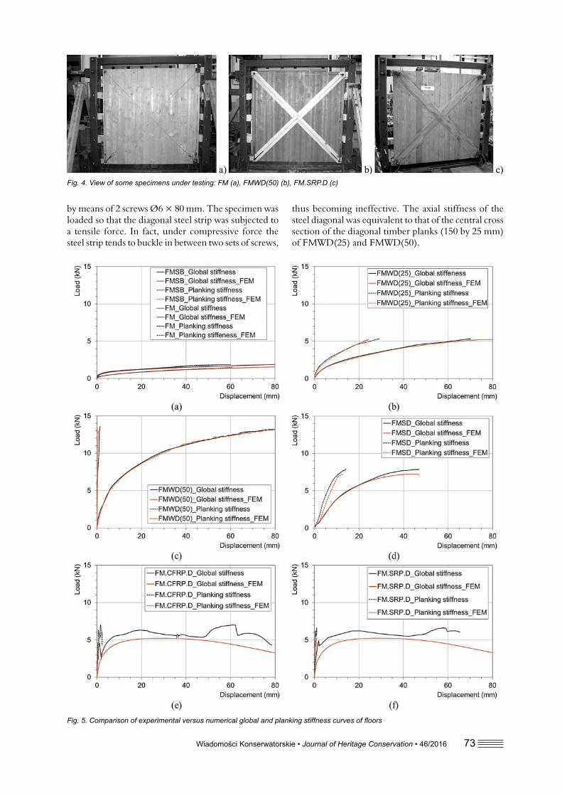
by means of 2 screws Ø6 × 80 mm. The specimen was loaded so that the diagonal steel strip was subjected to a tensile force. In fact, under compressive force the steel strip tends to buckle in between two sets of screws,
thus becoming ineffective. The axial stiffness of the steel diagonal was equivalent to that of the central cross section of the diagonal timber planks (150 by 25 mm) of FMWD(25) and FMWD(50).
Fig. 4. View of some specimens under testing: FM (a), FMWD(50) (b), FM.SRP.D (c)
Fig. 5. Comp arison of experimental versus numerical global and planking stiffness curves of fl oors

74 Wiadomości Konserwatorskie • Journal of Heritage Conservation • 46/2016
Specimens FM.CFRP.D and FM.SRP.D were strengthened with CFRP and SRP, respectively. The equivalence in terms of tensile axial stiffness was kept also in this case, by designing the width of the compos-ite material. Moreover, it is worth mentioning that the wet lay-up procedure might have reasonably helped in gluing not only fi bres to fl oorboards, but also boards to boards by fi lling the gaps with the epoxy primers and resins. This is itself an improvement of the in-plane capacity of the basic deck, besides the strengthening given by the fi bres.
The in-plane experimental test results are widely discussed in [14], [24]. Specimens FMSB and FM showed a relative rotation between boards and beams at failure. Due to the friction of the tongue-and-grove connection, a slightly better performance was observed for FMSB. In the specimen FMWD(25), the single diagonal plank working mainly in tension was able to improve the performance of the basic fl oor. The combination with an additional wooden diagonal, as in FMWD(50), further improved the performance, due to the simultaneous contribution in compression. For both diagonal strengthening methods the failure oc-curred at the screws connecting the thick planks to the beams. Specimen FMSD (punched steel strip) showed an intermediate behaviour between FMWD(25) and FMWD(50) ones. Specimens FM.CFRP.D and FM.SRP.D provided similar maximum loads to FMSD, but a much higher initial stiffness (Fig. 5).
UNI EN 12512 standard [25] was used to analyse the in-plane results, since it is applicable to general timber structure built with metal fasteners [14], [24]. The measured data at the intrados of the fl oors (thus including all the inelastic behaviours) were consid-ered, since they represent the global stiffness of the specimens and permit a more conservative type of analysis. In fact, not always it is possible to resort on the in-plane planking stiffness, due to the common lack in existing buildings of adequate boundary connections [2], [3], [5]. Fig. 5 shows both type of curves, for a comprehensive calibration of the inelastic FE models (details on the modeling are given in sec-tion 3). Table 2 lists the results in terms of global behaviour: Fmax is the maximum load at the displacement Vmax (equal 30 mm
for the current tests); Fy is the estimated load at yield-ing recorded by the global transducers and Vy is the correspondent displacement; Ky and Ku are the global initial and ultimate stiffness values, respectively. Results showed that the double wooden diagonal was the most effi cient intervention in terms of strength, while the application of composite materials resulted in a much stiffer in-plane behaviour, especially in the elastic branch. This was likely due to the stiffer response of the glued connection made by the epoxy resins [14].
3. NUMERICAL ANALYSES
Numerical models were developed to reproduce the behaviour of the push-out tests, thus to calibrate the inelastic response curves of the steel (nail and screws) connections presented in section 2.2. The calibrated behaviour of the connections was then used for mod-elling the in-plane behaviour of unstrengthened and diagonally reinforced timber fl oors. The beams and the steel strip were modelled with two-node beam ele-ments. Four-node shell elements were used for boards and composites. Nails and screws connections were modelled by non-linear elastic connection elements, which are practically spring elements with six Degrees of Freedom (DoF).
These elements served as an inelastic interface between all the construction elements (beams, boards, strips and composites) composing the fl oors [24]. Lastly, the connection elements were joined to the beams through rigid-link elements to respect the geometry of the fastening and supply the average ex-perimental lever arm between steel connectors. The frictional effect between boards was modelled again by means of connection elements with a simple sym-metric elasto-hardening behaviour [24]. Fig. 6 shows a schematic of the modelling strategy applied to the
Table 2. In- plane average global mechanical properties of timber fl oors
Sample Fmax (kN) Fy (kN) Vmax (mm) Vy (mm) Ky (kN/mm) Ku (kN/mm)FMSB 1.05 0.77 30 8.61 0.08 0.01
FM 1.44 0.90 30 2.67 0.29 0.02FMWD(25) 3.60 2.91 30 10.08 0.27 0.05FMWD(50) 10.25 7.41 30 8.34 0.80 0.13
FMSD 7.05 6.11 30 14.93 0.41 0.07FM.CFRP.D 6.34 3.16 22.02 1.59 1.85 0.31FM.SRP.D 6.22 3.74 22.76 2.28 1.50 0.25
Fi g. 6. Numerical model: (a) detail of connection between board and beam, (b) general view of PO.F1.M push-out model, (c) plane view of FMSD model extrados

Wiadomości Konserwatorskie • Journal of Heritage Conservation • 46/2016 75
push-out PO.F1.M and the fl oor FMSD specimens. The beams and the boards were modelled with the same orthotropic linear elastic material and by as-suming the following properties for spruce wood: E1 =11000 N/ mm2 as longitudinal elastic modulus; E2 = E3=367 N/mm2 as transversal elastic moduli; G12=687 N/mm2 as shear modulus; ν12,13=0.46 and ν21,31=0.03 as Poisson coeffi cients.
3.1. Push-out samples
The FE model of PO.F1.M was constructed accord-ing to the modelling strategy discussed above. The con-
nection given by every single nail was modelled with a connection element described with an inelastic curve, corresponding to the average experimental response of the three specimens PO.F1.M (Fig. 2a) divided by 16, which is the number of nails per each specimen. As expected, the numerical outcome matched the ex-perimental curve.
The numerical models of PO.F2a.M, PO.F2b.M and PO.F3.M were slightly more complex, due to the extra layers of boards added above the basic boarding. The connectivity between the layers of boards was made again with connection elements (Fig. 7). For the
Fi g. 7. Stresses along wood fi bres of FE models at 30 mm displacement and calibrated curves for steel connections at different planes: PO.F2a.M (a, b), PO.F2b.M (c, d) and PO.F3.M (e, f)
76 Wiadomości Konserwatorskie • Journal of Heritage Conservation • 46/2016
PO.F2a.M and PO.F2b.M there were two main groups of connection elements belonging to two distinct planes: the fi rst located between the beam and basic boarding, the second between the basic boarding and the strengthening board. For the PO.F3.M there was just an extra third plane of elements, due to the second strengthening board.
The calibrated curve from PO.F1.M was assigned to the connection elements simulating the nails whereas, for the connection elements simulating the screws, a dedicated curve was assigned per each plane. Each curve was calibrated according to an iterative proce-dure.
For the FE model PO.F2a.M (Fig. 7a,b), fi rstly the average experimental curve of the push-out test divided by 16 (n. of screws) was assigned as the hypo-thetical curve simulating one Ø6×100 mm screw of the second plane. The hypothetical curve of the nails plus screws of the fi rst plane was obtained as the aver-age experimental curve divided by 16 and multiplied by the ratio of the shear capacities of the two planes, computed according to the Johansen’s theory [23]. Secondly, the curve for the screws of the fi rst plane was obtained by subtracting that of nails, while the curve for the screws of the second plane was iteratively made stiffer until matching the experimental data (Fig. 2b). The calibration process for PO.F2b.M exactly followed that of PO.F2a.M (Fig. 2c; Fig. 7c,d). For PO.F3.M the procedure was slightly longer, since a third plane was added. Few more iterative calibration steps among the three planes of connection elements were carried out until the numerical curve matched the average experi-mental data (Fig. 2d; Fig. 7e,f). The modelling strategy demonstrated to be simple, robust and easy to calibrate once experimental data and failure mode for push-out tests are available.
3.2. Floor samples
The calibrated curves from the push-out tests were assigned to the nail and screws steel connections. The glued connections between fl oorboards and the CFRP or the SRP diagonal reinforcements were modelled as perfectly effi cient and modelled without any in-elastic interface connection element, but with rigid links. The connections of the punched steel strip to the fl oorboards were directly calibrated on the data of the timber fl oor by means of a trial and error process. For all the other connection elements the formerly calibrated curves were used. The composite materials were modelled as elastic orthotropic materials and the steel strip as an elasto-plastic material.
The estimations of the models were compared with the experimental results obtained from the displace-ment transducers, in order to check the ability of each model in fi ne describing the in-plane behaviour of the unstrengthened and strengthen fl oors [24]. Re-sults are concisely reported by the lateral load versus displacement curves at the global and planking levels.
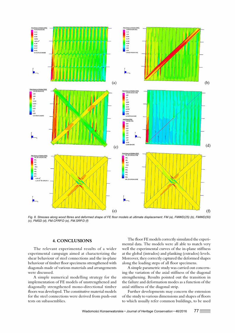
As shown in Fig. 5, the FE models were all able to match very well the experimental curves represent-ing the in-plane stiffness at the global (intrados) and planking (extrados) planes. The models correctly de-scribed the behaviour of the basic specimens FMSB and FM, and confi rmed that the in-plane strength and stiffness of basic fl oors was mainly given by the number of nails, their mutual spacing and, possibly, the additional friction between boards [24]. The offset in the curves of Fig. 5a was directly connected to the friction provided by the tongue and groove fi nish, which contributed in resisting against the relative slide of the fl oorboards (Fig. 8a). The curves of specimens FMWD(25), FMWD(50) and FMSD were also nicely reproduced and the stress contours (Fig. 8b, c, d) made explicit the strut and tie mechanism characterizing the effi ciency of these strengthening techniques. The numerical response of FM.CFRP.D and FM.SRP.D was very satisfactory. Anyhow, the models had some diffi culties in simulating the glued connection made by the epoxy resins. The gap between the numerical and experimental curves may be related to the effect of gluing of the resins between the boards. Nevertheless, also in these cases, the model correctly depicted the deformed shape at failure.
3.3. Preliminarily parametric study on the variation of stiffness of diagonal
strengtheningThe influence of the axial stiffness of the diagonal
strengthening on the in-plane response of timber floors was further examined by means of a prelimi-nary parametric study. The numerical model of a floor strengthened with a theoretical diagonal, FMDTH, was constructed using the calibrated data of the FM specimen. The theoretical diagonal strengthening was made with a strip having a cross section of 50 × 2 mm2 and a elastic modulus varying from 100 to 10000 N/ mm2, so that the axial stiffness (As) spanned from 10 kN to 10 MN. The strip was fully fixed to the planking via rigid connections resembling a glued connection.
Results showed that the global and planking stiff-ness curves started diverging after an axial stiffness of the diagonal above 150 kN (Fig. 9). Several of the experimental curves were above this value. This might be relevant for deciding at which strengthening level starting improving the connections within the timber fl oor and adding connection from the planking to the side walls. Moreover, the analysis pointed out the tran-sition from an almost purely shear deformation of the fl oor for As smaller than 20 kN to an almost rocking rotation of the planking for an As larger than 10 MN. In between these two limits for As, there is a combina-tion of the two deforming modes (see for instance Fig. 8b for FMWD(25) that resemble an As of 500 kN) and a progressive reduction of the failed nails connecting the boards to the beams.
Wiadomości Konserwatorskie • Journal of Heritage Conservation • 46/2016 77
4. CONCLUSIONS
The relevant experimental results of a wider experimental campaign aimed at characterizing the shear behaviour of steel connections and the in-plane behaviour of timber fl oor specimens strengthened with diagonals made of various materials and arrangements were discussed.
A simple numerical modelling strategy for the implementation of FE models of unstrengthened and diagonally strengthened mono-directional timber fl oors was developed. The constitutive material models for the steel connections were derived from push-out tests on subassemblies.
Fig. 8. St resses along wood fi bres and deformed shape of FE fl oor models at ultimate displacement: FM (a), FMWD(25) (b), FMWD(50) (c), FMSD (d), FM.CFRP.D (e), FM.SRP.D (f)
The fl oor FE models correctly simulated the experi-mental data. The models were all able to match very well the experimental curves of the in-plane stiffness at the global (intrados) and planking (extrados) levels. Moreover, they correctly captured the deformed shapes along the loading steps of all fl oor specimens.
A simple parametric study was carried out concern-ing the variation of the axial stiffness of the diagonal strengthening. Results pointed out the transition in the failure and deformation modes as a function of the axial stiffness of the diagonal strip.
Further developments may concern the extension of the study to various dimensions and shapes of fl oors to which usually refer common buildings, to be used

78 Wiadomości Konserwatorskie • Journal of Heritage Conservation • 46/2016
REFERENCES
[1] Modena C., Valluzzi M.R., da Porto F., Casa-rin F. Structural aspects of the conservation of historic masonry constructions in seismic are-as: remedial measures and emergency actions. International Journal of Architectural Heritage 2011;5(4–5):539–558.
[2] Branco J.M ., Tomasi R. Analysis and strengthening of timber fl oors and roofs. In: Costa A., Miranda Guedes J., Varum H. (ed) Structural rehabilitation of old buildings, series on Building pathology and rehabilitation. Vol. 2, Springer, Berlin, 2014, p. 235-258.
[3] Tomaževič M. Earth quake resistant design of masonry buildings. Imperial College Press, London, 1999.
[4] Peralta D.F. , Bracci M.J., Hueste M.D.B. Seismic behaviour of wood diagrams in pre 1950s unrein-forced masonry buildings. Journal of Structural Engineering – ASCE 2004;130(12):2040-2050.
[5] Brignola A., Pampanin S., Podestà S. Evaluation and control of the in-plane stiffness of timber fl oors for the performance-based retrofi t of URM buildings. Bulletin of the New Zealand Society for Earthquake Engineering 2009;42(3):204-221.
[6] Wilson A.W., Quenneville P.J.H., Ingham J.M. In-plane orthotropic behavior of timber floor diaphragms in unreinforced masonry buildings. Journal of Structural Engineering – ASCE 2014 140(1):04013038.
[7] Binda L., Car dani G., Saisi A., Valluzzi M.R. Vulnerability analysis of the historical buildings in seismic area by a multilevel approach. Asian Journal of Civil Engineering 2006;7(4):343-357.
[8] Valluzzi M.R. , Munari M., Modena C., Binda L., Cardani G., Saisi A. Multilevel approach to the vulnerability analysis of historic buildings in seismic areas – Part 2: Analytical interpretation of mechanisms for the vulnerability analysis and the structural improvement. International Journal
for Restoration of Buildings and Monuments 2007;13(6):427-441.
[9] Tomaževič M. The infl uence of rigidity of fl oors on the seismic behaviour of old stone-masonry buildings. European Earthquake Engineering 1991;5(3):28-41.
[10] Giuriani E. L’organizzazione degli impalcati per gli edifi ci storici. L’Edilizia, Speciale Legno Strutturale 20 04;134:30-43.
[11] Corradi M., Spera nzini E., Borri A., Vignoli A. In-plane shear reinforcement of wood beam fl oors with FRP. Composites Part B: Engineering 2006;37(4-5):310-319.
[12] Gattesco N., Marc orini L. In-plane stiffening techniques with nail plates or CFRP strips for timber floors in historical masonry buil-dings. Construction and Building Materials 2014;58(15):64-76.
[13] Tomasi R., Baldes sari C., Piazza M. The refurbish-ment of existing timber fl oors: characterization of the In-Plane behavior. In: Proc. Prohitech Conference, Rome, Italy, 22–24 June 2009, p. 255-260.
[14] Valluzzi M.R., Ga rbin E., Dalla Benetta M., Mo-dena C. Experimental characterization of timber floors strengthened by in-plane improvement techniques. Advanced Materials Research 2013; 778:682-689.
[15] Sorrentino L., M onti G., Kunnath S., Scalora G. Un modello meccanico semplifi cato accoppiato nel piano-fuori del piano per valutare il ruolo di solai, immorsature, qualità muraria e muri di controvento. In: XII Convegno “L’Ingegneria Sismica in Italia” ANIDIS 2007, Pisa, Italy, 10–14 June 2007 (CDRom).
[16] Moreira S., Ramos L .F., Oliveira D.V., Loure-nço P.B. Experimental behavior of masonry wall--to-timber elements connections strengthened with injection anchors. Engineering Structures 2014;81(15):98-109.
as reference for design of fl oors and their possible in-plane improvement with strengthening techniques.
ACKNOWLEDGEMENTS
The authors would like to thank Bozza Legnami (Vigonza, Italy) for supplying the timber, BASF (Tre-viso, Italy) and FIDIA Technical Global Service (Pe-rugia, Italy) for providing the composite systems. The collaboration of MSc A. Borsatto in the numerical FEM analyses is thankfully appreciated. The research was partially supported by the National project ReLUIS-DPC 2010–2013 (University Network of Seismic Engineering Laboratories) and the FP7 – European Project NIKER.
Fig. 9. Com parison between parametric curves of the theoretical fl oor FMDTH and those experimental
Wiadomości Konserwatorskie • Journal of Heritage Conservation • 46/2016 79
StreszczenieStropy drewniane w istniejących budynkach często
wymagają zastosowania rozwiązań usztywniających, aby poprawić ich pracę w warunkach naprężeń poziomych. Opracowywanie modeli takich elementów konstruk-cyjnych, z uwzględnieniem oddziaływania rodzaju, liczby i odkształcalności połączeń pomiędzy belkami a deskami, stanowi złożone zadanie i jest rozwijającym się obszarem badawczym.
Prezentując wyniki testów laboratoryjnych, przepro-wadzonych na przygotowanych modelach fragmentów stropów drewnianych (testy ślizgowe dla połączeń belka--deska), artykuł koncentruje się na kalibracji nieelastycz-nych modeli elementów skończonych, mających na celu odtworzenie pracy mechanicznej stropów poddanych monotonicznym próbom obciążenia w płaszczyźnie. Badane próbki były zbudowane z belek nośnych, do których deski były przymocowane po jednej lub po obydwu stronach za pomocą gwoździ i/lub wkrętów. Badano wpływ zastosowania na stropach przekątnych elementów usztywniających wykonanych z drewna, perforowanych pasów stalowych lub materiałów kom-pozytowych (CFRP lub SRP).
Przeprowadzono proste badanie dotyczące parame-trów z uwzględnieniem zmiennej sztywności teoretycz-nych przekątnych. Jego wyniki stanowią zbiór wstęp-nych danych, które mogą zostać wykorzystane w pro-jektowaniu ewentualnych rozwiązań wzmacniających do zastosowania na istniejących stropach drewnianych.
AbstractTimber fl oors in existing buildings often require
the adoption of stiffening techniques to improve their behaviour under horizontal actions. Modelling of such structural elements taking into account the infl uence of type, number and deformation capacity of the con-nections between beams and boards is quite complex and still under development.
Starting from laboratory experimental results car-ried out on assemblages (sliding tests on timber-to-board connections) the paper focuses on the calibra-tion of inelastic FE models aimed at reproducing the mechanical behaviour of fl oor specimens subjected to in-plane monotonic tests. Single and double boards connected with the bearing beams of the fl oor with nails and/or screws were examined on subassemblies. As regards fl oors, the effect of wood, punched steel strips or composite (CFRP or SRP) diagonals as stiff-ening techniques were studied.
A simple parametric study including the variation of stiffness of a theoretical diagonal was performed. Results constitute a preliminary set of data that may be used for design of possible improvement techniques to be applied on existing timber fl oors.
[17] Moon S.K., Lee D.G. Effect of in-plane fl oor fl e-xibility on the seismic behaviour of building struc-tures. Engineering Structures 1994;16(2):129-144.
[18] Kim S., White D.W. Nonlinear analysis of a one--story low-rise masonry buildings with fl exible diaphragms subjected to seismic excitation. Engi-neering Structures 2004;26(14):2053-2067.
[19] Valluzzi M.R., Garbi n E., Modena C. Flexural strengthening of timber beams by traditional and innovative materials. Journal of Building Appraisal 2007;3(2):125-143.
[20] Giordano G. Tecnica delle costruzioni in legno. Hoeply, Milano, 1999.
[21] UNI 9091–1 Wo od. Determination of moisture content. Electrical method. UNI, Milano, 1987.
[22] UNI EN 26891. Timber structures. Joints made
with mechanical fasteners. General principles for the determination of strength and deformation characteristics. UNI, Milano, 1991.
[23] Eurocode 5. EN 1995–1-1:2004. Design of timber structures – Part 1–1: General – Common rules and rules for buildings. CEN European Commit-tee for Standardization, 2004.
[24] Valluzzi M.R., Garbi n E., Dalla Benetta M., Mo-dena C. Experimental assessment and modelling of in-plane behaviour of timber fl oors. In: Proc. Intern. Conf. 6th Structural Analysis of Historical Constructions SAHC, Bath, UK, 2–4 July 2008, Vol. 2: 755-762.
[25] UNI EN 12512. Timber structures. Test methods. Cyclic testing of joints made with mechanical fasteners. UNI, Milano, 2006.