modeling the pneumatic subsystem of a s-cam air brake
TRANSCRIPT
MODELING THE PNEUMATIC SUBSYSTEM OF A S-CAM AIR BRAKE
SYSTEM
A Thesis
by
SHANKAR COIMBATORE SUBRAMANIAN
Submitted to the Office of Graduate Studies of Texas A&M University
in partial fulfillment of the requirements for the degree of
MASTER OF SCIENCE
May 2003
Major Subject: Mechanical Engineering
brought to you by COREView metadata, citation and similar papers at core.ac.uk
provided by Texas A&M University
MODELING THE PNEUMATIC SUBSYSTEM OF A S-CAM AIR BRAKE SYSTEM
A Thesis
by
SHANKAR COIMBATORESUBRAMANIAN
Submittedto TexasA&M Universityin partialfulfillm entof therequirements
for thedegreeof
MASTER OF SCIENCE
Approvedasto styleandcontentby:
K. R. Rajagopal(Co-Chairof Committee)
DvahgSwaroop(Co-Chairof Committee)
JoW. Howze(Member)
JohnWeese(Headof Department)
May 2003
Major Subject:MechanicalEngineering
iii
ABSTRACT
ModelingthePneumaticSubsystemof aS-camAir BrakeSystem.(May 2003)
ShankarCoimbatoreSubramanian,B.E.,Universityof Allahabad
Co–Chairsof AdvisoryCommittee:Dr. K. R. RajagopalDr. DvahgSwaroop
Theair brake systemis oneof thecritical componentsin ensuringthesafeoperation
of any commercialvehicle. This work is directedtowardsthedevelopmentof a fault-free
modelof the pneumaticsubsystemof the air brake system. This model canbe usedin
brake controlanddiagnosticapplications.Currentenforcementinspectionsaredoneman-
ually andhencearetime consumingandsubjective. Thelong-termobjective is to develop
a model-based,performance-baseddiagnosticsystemthat will automateenforcementin-
spectionsandhelp in monitoring thecondition of theair brake system.Sucha diagnostic
systemcan updatethe driver on the performanceof the brake systemduring travel and
with recentadvancementsin communication technology, this informationcanberemotely
transferredto thebrake inspectionteams.Sincethis systemis performance-based,it will
eliminatethesubjective natureof visual inspections.Thefirst stepin thedevelopmentof
suchadiagnosticsystemis to obtaina fault-freemodelof theair brakesystem.Themodel
of the pneumatic subsystemcorrelatesthe pressuretransientsin the brake chamberwith
thebrake pedalactuationforceandthebrake valve plungerdisplacement.An experimen-
tal testbenchwassetup at TexasA&M University andthe experimentaldatais usedto
corroborate theresultsobtainedfrom themodel.
iv
To my parentsMrs. JayalakshmiandMr. C. R. Subramanian
v
ACKNOWLEDGMENTS
I amvery fortunateto bea studentof Prof. K. R. Rajagopal.It is a greatprivilegeto
work underhis guidanceandI hopeI cantake full advantageof this opportunity. I thank
him for spendinghis valuabletime in guiding andmotivating me in this thesis. Next, I
expressmy gratitudeto Prof. DarbhaSwaroopwhohelpedmeall alongthewayduringthe
courseof this project. I thankhim for all his weekendlectureson ControlSystemsandI
look forward to learningmorefrom him. I thankProf. JoW. Howze for kindly agreeing
to bea memberof my thesiscommittee. I amgratefulto him for meetingmewhenever I
needed.
I amvery lucky to bein thesameofficeasDr. Luoyi Tao. I thankhim for hisvaluable
suggestionsduringthecourseof this project.My specialthanksto Dr. J.Murali Krishnan
for his valuablehelpwhenever I neededit. His inputswereinvaluablewhile settingup the
experimentalsetupandI thankhim for hiskindnessandgenerosity. I thankKrishnafor his
helpduring theexperimentalstageandhis inputs during themodeling phase.I thankmy
goodfriendParagfor hispromptassistancewhenever I requestedhim.
Finally, I am indebtedto my parentsfor their love andblessings.It is due to their
neverendingsupportandencouragementthatI havebeenableto reachthisposition in life.
I cannever repaythemfor their sacrificesin bringingmeup andallowing meto studyin
the UnitedStates.I feel blessedto have a loving sister, brother-in-law andnephew andI
thankthemfor their loveandaffection.

vi
TABLE OF CONTENTS
CHAPTER Page
I INTRODUCTION ��������������������������������������������������� 1
A. Background. . . . . . . . . . . . . . . . . . . . . . . . . . . . 1B. Aim andScopeof theThesis. . . . . . . . . . . . . . . . . . . 4C. Organization of theThesis . . . . . . . . . . . . . . . . . . . . 6
II AN OVERVIEW OF THE AIR BRAKE SYSTEM ����������������� 7
A. ThePneumaticSubsystem. . . . . . . . . . . . . . . . . . . . 7B. TheMechanicalSubsystem . . . . . . . . . . . . . . . . . . . 7
III THE EXPERIMENTAL SETUP ������������������������������������� 10
IV MODELING THE AIR BRAKE SYSTEM ������������������������� 13
A. ThePrimaryCircuit . . . . . . . . . . . . . . . . . . . . . . . 14B. TheSecondaryCircuit . . . . . . . . . . . . . . . . . . . . . . 19C. ModelingtheFluid Flow . . . . . . . . . . . . . . . . . . . . . 22
V CORROBORATION OF THE MODEL ����������������������������� 35
VI CONCLUDINGREMARKSAND FUTUREWORK ��������������� 41
REFERENCES ��������������������������������������������������������������������� 42
VITA ��������������������������������������������������������������������������������� 45
vii
LIST OFTABLES
TABLE Page
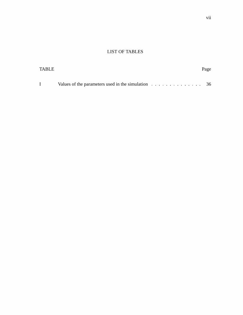
I Valuesof theparametersusedin thesimulation ��������������������������� 36
viii
LIST OFFIGURES
FIGURE Page
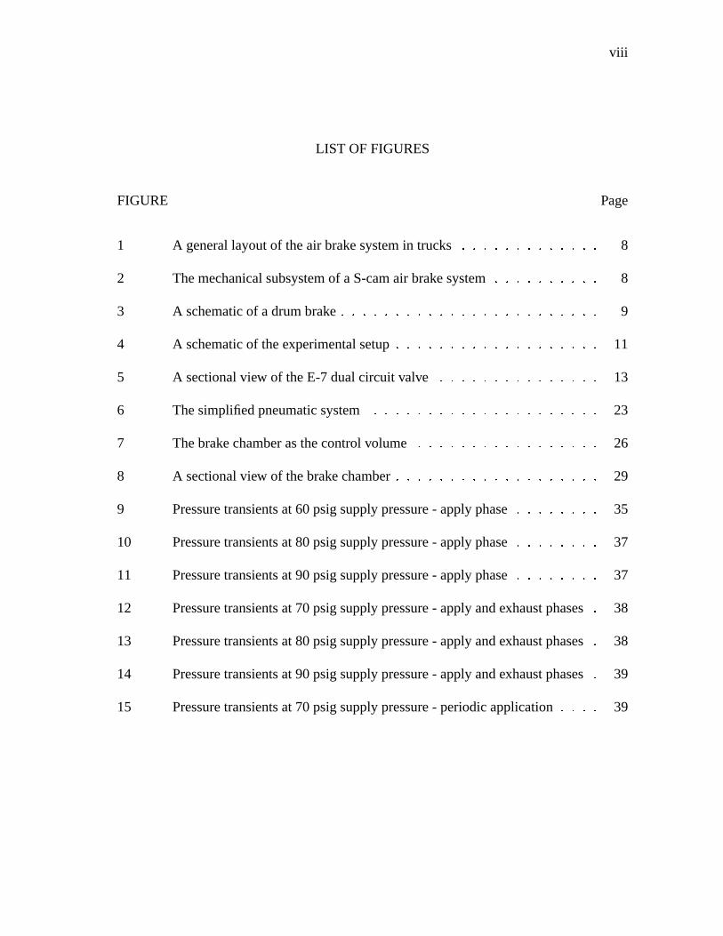
1 A generallayoutof theair brakesystemin trucks ������������������������� 8
2 Themechanicalsubsystemof aS-camair brakesystem ������������������� 8
3 A schematicof adrumbrake ����������������������������������������������� 9
4 A schematicof theexperimentalsetup ������������������������������������� 11
5 A sectionalview of theE-7dualcircuit valve ����������������������������� 13
6 Thesimplifiedpneumaticsystem ����������������������������������������� 23
7 Thebrakechamberasthecontrolvolume ��������������������������������� 26
8 A sectionalview of thebrakechamber������������������������������������� 29
9 Pressuretransientsat60psigsupplypressure- applyphase ��������������� 35
10 Pressuretransientsat80psigsupplypressure- applyphase ��������������� 37
11 Pressuretransientsat90psigsupplypressure- applyphase ��������������� 37
12 Pressuretransientsat70psigsupplypressure- applyandexhaustphases � 38
13 Pressuretransientsat80psigsupplypressure- applyandexhaustphases � 38
14 Pressuretransientsat90psigsupplypressure- applyandexhaustphases � 39
15 Pressuretransientsat70psigsupplypressure- periodicapplication ������� 39

1
CHAPTERI
INTRODUCTION
A. Background
The brake systemis oneof the critical componentsin ensuringthe safetyof any vehicle
on the road. Most tractor-trailer vehicleswith a grossvehicleweight rating over 19,000
lb, mostsingletruckswith a grossvehicleweight rating over 31,000lb, mosttransitand
inter-city buses,andabouthalf of all schoolbusesareequippedwith air brakesystems[23].
More than85%of thecommercialvehiclesoperatingin theUnitedStatesuseS-camdrum
foundation brakesin theirair brakesystem[23]. Theperformanceof air brakesystemsused
in commercialvehiclesis very sensitive to maintenanceproceduressuchasadjustmentof
pushrod stroke, brake lining replacement,etc. [16]. Malfunctioning brakes are one of
the leadingmechanicalcausesof accidentsin commercialvehicles.In 1999,amongfatal
crashesthatinvolvedmechanicalconditionsasacause,28.3%wereattributedto defectsin
thebrake system[22]. In roadsideinspectionsperformedbetween1996and1999,29.3%
of all the vehicle-relatedviolations amongIntrastatecarriersand37.2%of thoseamong
Interstatecarriersweredueto defectsin thebrakesystem[7].
RegulationssuchastheFederalMotor VehicleSafetyStandards(FMVSS)121(effec-
tive 1973)governthebrakingperformanceof commercialvehicleson roadsin theUnited
States.FMVSS121specifiesastoppingdistancecriterionandacriterion for lateralvehicle
stability, requiringa vehicleto staywithin a twelve feet lanewhenperforming a stopping
maneuver [21]. Althoughregularmaintenanceinspectionsarecarriedby truckownersand
fleetoperatorsto conformto FMVSS121,governmentagenciessuchastheOfficeof Motor
Carriersconductenforcementinspectionsin the interestof public safety. The criteria set
Thejournalmodelis IEEETransactionsonAutomatic Control.

2
by theCommercialVehicleSafetyAlliance (CVSA) guidesuchenforcementinspections.
Inspectiontechniquesthat areusedfor monitoring the brake systemin commercial
vehiclescanbebroadlyclassifiedinto two categories- visualinspectionsandperformance-
basedinspections[19]. Visual inspectionsinvolve themeasurementof thepushrod stroke
andthethicknessof thebrake padlining andcheckingthebrake linesfor wearandleaks.
Visualinspectionsaresubjective,timeandlaborintensiveandareinconvenientonvehicles
with low ground clearance.Performance-basedinspectionsinclude the measurementof
brakingforce andtorque,vehicledeceleration,stoppingdistance,brake padtemperature
etc. Such inspectionsare more objective and offer a more effective assessment of the
conditionof theair brake system.Currently, suchinspectionsarerequiredin Europeand
areperformedonly in certifiedinspectiongarages[19]. It is appropriateto point out that,
in anappraisalof thefutureneedsof thetrucking industry[3], theauthors,who represent
a broadspectrumof the trucking industry, indicatethat equipment userswould greatly
appreciatethedevelopmentof a standardized,universal,hand-helddiagnostictool. They
alsostresstheneedfor improvementsin theexisting inspectiontechniquesandadvisethe
needfor the developmentof performance-basedtools that canbe usedalongwith visual
inspections.
An air brake systemdiffersfrom a hydraulic brake systemusedin passengervehicles
in many ways.Themostimportantdifferenceis themodeof operation- in ahydraulicbrake
system,thepedalforceappliedby thedriver (augmentedusuallyby a vacuumbooster)is
transmittedthrough thebrake fluid resultingin theapplicationof thefoundationbrakeson
thewheels,whereas,in anair brake system,theapplicationof the treadlevalve regulates
theair supplyfrom asupplyreservoir to thebrakechamber. As a result,very little sensory
feedbackis availableto thedriverof acommercialvehiclewhencomparedto avehiclewith
a hydraulic brake system.Anotherdifferencebetweenthe two brakingsystemsis in the
distribution of thebrakingforcebetweenthevariousaxles.In passengervehicles,theload

3
distribution on theaxlesvariesslightly whereasin commercialvehiclesthedistribution of
theloadonthevariousaxlesvariessignificantlydependingonwhetherthevehicleis loaded
or unloaded.Typically, commercialvehiclebrakesaredesignedandbalancedfor thefully
loadedconditionandthis resultsin excessive brakingon someaxleswhenthe vehicleis
empty[16]. This problemis compoundedby the fact that theU.S. regulations,unlike the
Europeanstandards,doesnot directly specifybrake forcedistribution betweenthevarious
axles[17].
In additionto theS-camfoundationbrakes,retardersarebeingusedassupplementary
brakingmechanisms.Compressionbrakesarecommonlyusedasretardersin currentcom-
mercialvehiclesandthey serve to decreasethework loadonthefoundationbrakesthereby
increasingthe life of the foundation brakes[5]. The main limitation of suchretardersis
that they canonly supplementthe friction brakesandcannever replacethemcompletely.
This is dueto thepoor torqueoutputcharacteristicsof theretardersat low vehiclespeeds
andmoreover they cannotprovideany brakingeffort whenthevehicleis at rest[13].
The hydraulic brake systemhasbeenextensively studiedandmodelsfor the system
have beendevelopedby many authors.Gerdeset al. [6] developeda modelfor ahydraulic
brake systemwith a vacuumbooster. They combineda staticvalve modelwith equations
of air flow within the booster. Khan et al. [9] usedbond graphtechniquesto develop
modelsfor the booster, the mastercylinder and the wheel cylinder. In both cases,the
authorsmeasuredthewheelcylinderchamberpressureasa functionof timeandattempted
to predictthepressuretransientswith theirmodels.
Theair brakesystemusedin commercialvehiclesis madeupof two subsystems- the
pneumaticsubsystemandthe mechanicalsubsystem.The pneumaticsubsystemincludes
thecompressor, thestoragereservoirs, thebrake lines, the treadlevalve andterminatesat
thebrake chamber. Themechanicalsubsystemstartsfrom thebrake chamberandincludes
thepushrod,theslackadjuster, theS-camandthebrakepads.Thus,it canbeseenthatde-
4
velopingamodelfor theair brakesystemis acomplicatedprocessdueto thelargenumber
of componentsinvolved. The majority of the publishedwork on air brake systemsrelate
brake force,vehicledeceleration,brake padtemperatureandbrake torqueasa functionof
brake chamberpressureandpushrod stroke [8], [15], [18], [20]. In all the experiments,
the brake chamberpressurewasmeasuredfor eachapplicationandwascorrelatedwith
othermeasurementssuchasthosementionedabove. This is essentiallyanindicationof the
characteristicsof themechanicalsubsystemof theair brakesystem.
A modelfor thepneumaticsubsystemmustbeableto predictthepressuretransients
in thebrake chamberasa functionof thesupplypressurefrom thereservoir andthepedal
forceappliedby thedriver. More recently, Acarmanet al. [1] suggestedamodelto predict
thegrowthof air pressurein thebrakechamberof abrakesystemequippedwith anAntilock
BrakingSystem(ABS). They usedorificeflow equationsto modelthedynamicsof air flow
andincludedthedynamicsof amodulator locateddownstreamfrom thetreadlevalve. The
modulatorregulatesthe pressureof air in the brake chamberdependingon the modeof
operationasdecidedby theABS controller.
B. Aim andScopeof theThesis
The aim in this thesisis to develop a model that canpredict the pressuretransientsover
a wide rangeof supplypressuresandalsoat partial brake applications.Sucha model is
highly desirablesince,accordingto [12], almost97%of typical servicebrake applications
in commercialvehiclesaremadebelow 30 psig. Thepneumaticsubsystemis modeledso
thatthepressuretransientsin thebrakechambercanbepredictedfrom themeasurementsof
thepedalforceandpedaldisplacement.Thedynamicsof thetreadlevalve is incorporated
into themodelandthetreadlevalve is treatedasanozzle.Thereasonbehindthischoiceis
explainedin Chapter(IV).

5
Certainassumptionshave beenmadein the developmentof the model. A lumped
parameterapproachis adoptedin modelingboth themechanicalcomponentsof thevalve
andtheflow of air in thesystem.Theviscosityof air hasbeenneglectedandit is assumed
to behave like anidealgas.Theexpansionprocessin thevalve is assumedto beisentropic
anda coefficient of discharge usedto accountfor the lossesduring expansion. It is also
assumedthat the flow from the valve to the brake chamberbe adiabatic. All the above
assumptionsareapproximationsto therealprocessandthechoiceof theseapproximations
is supportedby thefactthattheresultsfrom themodeldevelopedundertheseassumptions
agreewell with theexperimentaldataaswill beseenlaterin Chapter(V).
Thelong-termaim is to developanon-board,model-based,performance-baseddiag-
nostictool thatcanbeusedin inspectingtheair brake system.Sucha diagnostictool can
frequentlyupdatethe driver on the performanceof the brake systemduring travel. With
recentadvancementsin communicationtechnology, it is alsopossibleto transferthediag-
nosticinformationremotelyto theroadsideinspectionteamswhichwill reducetheinspec-
tion timesignificantly. This is desirablesince,accordingto [11], theaveragetime required
for a typical roadsideinspectionis around30minutes,with approximatelyhalf of thetime
spenton brakes. Sincethe diagnosticsystemis performance-based,it will eliminatethe
subjectivenatureof visualinspections.
The first stepin the developmentof sucha diagnostictool is the developmentof a
fault-free model of the air brake system. In this thesis,we deal with the modelingof
the pneumaticsubsystemof the air brake system. The resultsfrom the model will be
corroborated with the dataobtainedfrom the experimentsfor varioustest runs. Oncea
modelis developedfor thepneumaticsubsystem,it canbecombinedwith a modelfor the
mechanicalsubsystemto obtaina completemodelof the air brake system. A fault-free
modelof theair brake systemwill beableto predictthebrake chamberpressure,thepush
rod stroke, the brake torqueandthe wheelspeedfrom measurementsof the brake valve

6
plungerdisplacementandthebrake pedalactuationforce. Thus,a fault-freemodelgives
a correlationbetweenthe above mentionedvariablesundernormaloperatingconditions.
Theuseof this fault-freemodelin thediagnosticsystemwill help in detectingfailuresin
theair brakesystemwhenever they occur.
C. Organizationof theThesis
ChapterII presentsadescriptionof thepneumaticandthemechanicalsubsystemsof theair
brakesystem.ChapterIII outlinesthedetailsof theexperimentaltestbenchsetupatTexas
A&M University. InformationregardingthevarioustransducersandtheDataAcquisition
(DAQ) systemusedis alsogivenin thischapter. ChapterIV presentsadetaileddescription
of the model of the pneumaticsubsystem.The equationsgoverning the motion of the
variouscomponentsof thevalve arederivedfollowedby theequationsdescribingtheflow
of air in thesystem.In ChapterV we look at the resultsobtainedfrom thesimulation of
themodelfor varioustestruns. Theseresultsarecorroboratedwith theexperimentaldata
collectedfor eachtestrun. ChapterVI providesa summaryof resultsandscopefor future
work.

7
CHAPTERII
AN OVERVIEW OF THE AIR BRAKE SYSTEM
A. ThePneumaticSubsystem
A generallayoutof thepneumaticsubsystemin theair brake systemof a tractor-trailer is
shown in Fig. 1. Thecompressorchargesup thestoragereservoirs andtheapplicationof
thetreadlevalvemodulatestheamountof air providedto thebrakechambers.Compressed
air is suppliedfrom the treadlevalve to the variousbrake chambersthroughtwo circuits
- the primary circuit andthe secondarycircuit. Theadvantageof suchanarrangementis
thatpartialbrakingis possiblein thecaseof failureof oneof the two circuits, thoughthe
complexity of thesystemis increased.In trucks,theprimarycircuit providescompressed
air to the rear brakes and the secondarycircuit operatesthe front brakes. Since1968,
federalstandardshave warrantedthe useof dual-circuit valve brake systemsin carsand
otherpassengervehiclesandsincethemid-1970’sthiswasextendedto includecommercial
vehicleswith air brake systems[4]. FMVSS 121 spellsout the performancestandards
requiredfor air brake systemsandFMVSS105providesthestandardsfor hydraulicbrake
systems.
B. TheMechanicalSubsystem
The mechanicalsubsystemof the S-camair brake systemis illustratedin Fig. 2. Com-
pressedair actsonthebrakechamberdiaphragmproviding amechanicalforcethatis trans-
mitted to the brake padsthroughthe pushrod andthe S-cam.The force outputfrom the
pushrod to thebrake padsdecreasesrapidly whenits stroke exceedsa certainlimi t [20].
The stroke of the pushrod increasesdueto the wearof the brake linings andalsodueto
the expansionof the brake drum asa consequenceof the heatgeneratedduring braking.

8
Fig. 1. A generallayoutof theair brakesystemin trucks
Automaticslackadjustersareusedto compensatefor this increasein stroke.
Fig. 2. Themechanicalsubsystemof aS-camair brakesystem
Drum brakes(seeFig. 3) arethemostcommonfoundation brakesfoundin commer-
cial vehiclesin theUnitedStates,whereasin Europediscbrakesareslowly replacingdrum
brakesover thepastdecade[4]. Disc brakesoffer lower sensitivity of thebrake torqueto

9
thebrakepadfrictioncoefficient,betterfaderesistanceandimprovedbrakeefficiency when
comparedto drumbrakes. Their main limitation is theabsenceof “self-energization” [4]
(this term refersto the augmentationof the momentdueto the actuationforce actingon
the brake padby the momentdueto the friction force actingon the brake pad)available
in drumbrakesresultingin theneedfor higheractuationair pressureswhencomparedto
drumbrakes.
Fig. 3. A schematicof adrumbrake

10
CHAPTERIII
THE EXPERIMENTAL SETUP
The experimental testbenchat TexasA&M University is essentiallythe front axle of a
tractor. Compressedair is providedby aCampbellHausfeldoil-lesscompressorwhichhas
a maximumpressurerating of 120 psi. It hasa six gallon storagetank with a dial gage
indicatingthe pressureof the compressedair storedin the tank. A drain cock, locatedat
thebottomof thestoragetank,is usedto periodicallyremove themoistureaccumulatedin
thetank.Thecompressoris poweredelectricallyandapressureswitchshutsit down when
the pressurein the tank reaches120 psi andturnsit on whenthe pressuredropsdown to
around105psi. A pressureregulator(Manufacturer- OmegaEngineering,ModelNumber
PRG501-120)is providedto modulatethepressureof theair beingsuppliedto thetreadle
valve. Fig. 4 showsaschematicof theexperimentalsetup.
The treadlevalve usedis the E-7 dual circuit valve manufacturedby Allied Sig-
nals/Bendix(seeFig. 5). The primary circuit is actuatedby the pedalforce andthe sec-
ondarycircuit actsessentiallyasarelayvalve. Undernormaloperatingconditions,air bled
off from the primary delivery is usedto actuatea relay pistonwhich in turn actuatesthe
secondarycircuit. Whentheprimarycircuit fails, thesecondarycircuit is actuateddirectly
by pedalforce.Whenthebrakepedalis applied,theprimarypistonfirst closestheprimary
exhaustandthenopenstheprimaryinlet valve. This is theapplyphase.Whenthedelivery
pressureincreasesto a level whereit balancesthepedalinput force,theprimaryinlet valve
is closedwith theprimaryexhaustalsoremaining closed.This is thebalanceor thehold
phase.Whenthepedalis released,so is thebalancingforceon theprimarypiston,which
causestheprimarypistonto lift off from theprimaryexhaustseatandtheair in thedeliv-
ery circuit is exhaustedto theatmospheretherebyreleasingthebrakes.This is theexhaust
phase.Thesecondarycircuit functionsin asimilarmannerexceptfor thefactthattherelay

11
pistonis usedto actuateit undernormaloperatingconditions.
Fig. 4. A schematicof theexperimentalsetup
The compressedair from the treadlevalve is suppliedto the brake chamberthrough
brake hoses.A pneumaticactuatoris usedto applythetreadlevalve. Theair supplyto the
pneumaticactuatoris providedfrom thestoragetank througha pressureregulator similar
to theoneusedfor regulatingthesupplypressureto thetreadlevalve. Thebrake chamber
is a “Type-20”brakechamber, i.e., it hasacross-sectionalareaof 20 in2. Thestrokeof the
pushrod rotatestheS-camthroughtheautomaticslackadjuster. Therotationof theS-cam
in turnpushesthebrakeshoesagainstthebrakedrum.
The axial displacementof the treadlevalve is measuredwith a linear potentiome-
ter having a maximumstroke of 3���
(Manufacturer- Omega Engineering,Model Number
LP802-75). An input excitation of 5 V d.c. is providedto the potentiometerby a power
source(Manufacturer- Omega Engineering,Model NumberPSS-5A).Thepotentiometer

12
hasbeencalibratedandit is foundto besufficiently linear in therangeof interest.A load
cell (Manufacturer- Omega Engineering,Model NumberLC203-1K)is mountedbetween
theactuatingshaftof thepneumatic actuatorandtheplungeron thebrake pedal. It is ex-
cited by a 10 V d.c. power supply(Manufacturer- Omega Engineering,Model Number
DMD-465WB) andhasa full scaleoutputof 20 mV. This outputis amplifiedthroughan
amplifier which is built in the power supplyof the load cell. A pitot tubeassemblywas
speciallyfabricatedandcalibratedin orderto measuretheMachnumbersin theflow at the
entranceof the brake chamber. The pitot tubewasmountedat the entranceof the brake
chamberandtwo pressuretransducerswereusedto measurethestaticandthestagnation
pressures.The pressuretransducer(Manufacturer- Omega engineering,Model Number
PX181-100G5V)hasa rangeof 0-100psig. An excitationof 24 V d.c. is providedto the
pressuretransducerby a power supply(Manufacturer- Omega Engineering,Model Num-
berU24Y101)andthevoltageoutputof thetransduceris from 1 to 5 V d.c. Thepressure
transducerhasa responsetime of lessthan5 milliseconds.Thetransducersareinterfaced
with aconnectorblock throughshieldedcables.Datais collectedthroughaPCI-1200Data
Acquisition (DAQ) board(Manufacturer- NationalInstruments)andtheconnectorblock
is interfacedwith the DAQ boardvia a ribbon cable. An applicationprogramwritten in
MATLAB recordsall thecollecteddataandplots it. A low-passdigital filter [14], with a
cut-off frequency of 20Hz., is usedto filter thecollecteddata.

13
CHAPTERIV
MODELING THE AIR BRAKE SYSTEM
A lumpedparameterapproachhasbeenadoptedin modelingthepneumatic subsystemof
theair brake system.A modelfor thepneumaticsubsystemof theair brake systemmust
take into considerationthedynamicsof thetreadlevalve andtheflow of air in thesystem.
A sectionalview of the theE-7 dualcircuit valve is shown in Fig. 5. We will now derive
theequationsof motionof thecomponentsof thetreadlevalve.
Fig. 5. A sectionalview of theE-7dualcircuit valve
Let Fp denotetheforceinputto thevalveplunger. Let xp denotetheaxialdisplacement
of theplungerfrom its initial position.Let xpp andxpv denotethedisplacementof thepri-
14
marypistonandtheprimary valveassemblygasket from their initial positionsrespectively.
Let xpt denotethedistancetraveledby theprimary pistonbeforeit closestheprimaryex-
haust.Let Kss, Kpp andKpv denotethespringconstantsof thestemspring,primarypiston
returnspringandthe primary valve assemblyreturnspringrespectively. Let xrp andxsv
denotethedisplacementof therelaypistonandthesecondaryvalve assemblygasket from
their initial positionsrespectively. Let xst denotethedistancetraveledby the relaypiston
beforeit closesthesecondaryexhaust.Let Krp andKsv denotethespringconstantsof the
relaypistonreturnspringandthesecondaryvalveassemblyreturnspringrespectively.
Weassumethefrictionat theslidingsurfacesto benegligible. This is reasonablesince
theslidingsurfacesarelubricatedwith grease.Thespringsin thetreadlevalveweretested
andfoundto belinear in theregion of their operation.Thus,thespringscanbedescribed
by theconstitutive equation,F � Kx, whereF is thenet forceappliedon thespring,x is
thedeflectionof thespringfrom its initial positionandK is thespringconstant.Thespring
constantsandthe initial pre-loadson the springsweremeasuredandusedin the model.
Geometricparameterssuchasareas,initial deflections,etc. werealsomeasuredandused
in thefollowing equations.
A. ThePrimaryCircuit
We modeltheprimarycircuit for its differentphasesof operation.Theequationof motion
of theprimarypistontill it closestheexhaustport canbewrittenas,
Mppd2xpp
dt2 � Fp � Kss�xpp � xp �� Kppxpp � Fkppi (4.1)
whereMpp is themassof theprimarypistonandFkppi is theinitial pre-loadon theprimary
pistonreturnspring.

15
Theequationof motionof theprimarypistonduringtheapplyandholdphasescanbe
writtenas,
Mppd2xpp
dt2 � Fp � Kss�xpp � xp �� Kppxpp � Fkppi � Fpp � F p1
reacn � F p2reacn (4.2)
whereFpp is the net pressureforce acting on the primary piston, F p1reacn is the reaction
forceappliedby theprimary valve assemblygasket on theprimarypistonandF p2reacn is the
reactionforceappliedby therelaypistonstemon theprimarypiston.
The equationof motion of the primary valve assemblygasket during the apply and
holdphasescanbewrittenas,
Mpvd2xpv
dt2 � F p1reacn � Kpvxpv � Fkpvi � Fpv (4.3)
whereMpv is the massof the primary valve assemblygasket, Fkpvi is the initial pre-load
on theprimary valve assemblyreturnspringandFpv is thenetpressureforceactingon the
primaryvalveassemblygasket.
Addingequations(4.2)and(4.3)andre-arrangingthetermsresultsin,
Mppd2xpp
dt2 ��Kss � Kpp � xpp � Mpv
d2xpv
dt2 � Kpvxpv
� Kssxp � Fp � Fkppi � Fkpvi � Fpp � Fpv � F p2reacn (4.4)
Thethreestagesof operationof theprimary circuit canbedescribedby thefollowing
relations:
� Apply Phase
xpp xpt (4.5)

16
� Hold Phase
xpp � xpt (4.6)
� ExhaustPhase
xpp � xpt (4.7)
Now, atany instantof time duringtheapplyandholdphases,
xpv�t � � xpp
�t �� xpt (4.8)
Makinguseof equation(4.8),wecanrewrite equation(4.4)asthefollowing,
�Mpp � Mpv � d2xpp
dt2 ��Kss � Kpp � Kpv � xpp � Kpvxpt
� Kssxp � Fp � Fkppi � Fkpvi � Fpp � Fpv � F p2reacn (4.9)
WenotethatthethreetermsKpvxpt , Fkppi andFkpvi areindependentof timeandhence
combinethemasasingleconstantF1 givenby,
F1 � Kpvxpt � Fkppi � Fkpvi (4.10)
Next, wedefinetheconstantK2 as,
K2 � Kss � Kpp � Kpv (4.11)
Now, let us look at the term Fpp, which is the pressureforce actingon the primary
pistondueto theprimarydeliveryair. Let App bethenetareaof theprimary pistonexposed
to thedeliveredpressurizedair. Assumingthepressureto beuniform over thesurfaceof
theprimarypiston,thetermFpp canbewrittenas,
Fpp � �Ppd � Patm � App (4.12)
wherePpd is thepressureof theprimarydelivery air at any instantof time andPatm is the

17
atmosphericpressure(all thepressuretermsusedhererepresentabsolutepressures).
Next, let us considerthe term Fpv, which is the net pressureforce actingon the pri-
maryvalveassemblygasket. Let Apv1 andApv bethenetcross-sectionalareaof theprimary
valveassemblygasketexposedto thepressurizedair at thesupplyandthedelivery respec-
tively. Underthesameassumptionsasaboveandalsoassumingthegasketto besufficiently
rigid (which is reasonablesincethegasket is enclosedby a metalring), we canwrite the
expressionfor Fpv as,
Fpv � PpsApv1 � PpdApv (4.13)
wherePps is thesupplyair pressureto theprimarycircuit.
Usingequations(4.10)to (4.13), equation(4.9)canbenow writtenas,
�Mpp � Mpv � d2xpp
dt2 � K2xpp � Kssxp � Fp
� F1 � Ppd�App � Apv �� PpsApv1 � F p2
reacn � PatmApp (4.14)
Equation(4.14) representsthe dynamicsof the primary circuit during the apply and
hold phases.We now assumethe inertia of the primary pistonandthe primary valve as-
semblygasket to besmall comparedto theotherforces. With this assumption,theabove
equationreducesto thefollowing,
K2xpp � Kssxp � Fp � F1 � Ppd�App � Apv ��� PpsApv1 � F p2
reacn � PatmApp (4.15)
This equationis usedwith equation(4.65), which will be derived in section(C) of
this chapter, to obtaintheresponseof theprimarycircuit to variouspedalinputs.Theterm
F p2reacn is obtainedfrom equation(4.20),which will bederived in the following section.It
shouldbe notedthat this term will be presentin the above equationonly till the primary
pistonandtheprimary valve assemblyarein contactwith therelaypiston. At somepoint
18
during the apply phase,this contactwould be broken andthenthis term would be set to
zero.
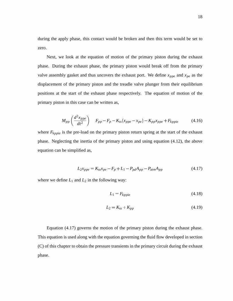
Next, we look at the equationof motion of the primary piston during the exhaust
phase. During the exhaustphase,the primary pistonwould breakoff from the primary
valve assemblygasket andthusuncoverstheexhaustport. We definexppe andxpe asthe
displacementof the primary pistonandthe treadlevalve plungerfrom their equilibrium
positionsat the start of the exhaustphaserespectively. The equationof motion of the
primarypistonin this casecanbewrittenas,
Mppd2xppe
dt2 � Fpp � Fp � Kss�xppe � xpe �� Kppxppe � Fkppie (4.16)
whereFkppie is thepre-loadon theprimary pistonreturnspringat thestartof theexhaust
phase.Neglectingthe inertia of the primary pistonandusingequation(4.12), the above
equationcanbesimplifiedas,
L2xppe � Kssxpe � Fp � L1 � PpdApp � PatmApp (4.17)
wherewedefineL1 andL2 in thefollowing way:
L1 � Fkppie (4.18)
L2 � Kss � Kpp (4.19)
Equation(4.17)governsthe motion of the primary pistonduring the exhaustphase.
Thisequationis usedalongwith theequationgoverning thefluid flow developedin section
(C) of thischapterto obtainthepressuretransientsin theprimarycircuit duringtheexhaust
phase.

19
B. TheSecondaryCircuit
Wenow modelthesecondarycircuit of thetreadlevalvefor its variousphasesof operation.
Theequationof motionof therelaypistontill it closestheexhaustport is givenby,
Mrpd2xrp
dt2 � F p2reacn � Frpd � Krpxrp � Fkrpi � PatmA
�rp (4.20)
whereMrp is themassof therelaypiston,F p2reacn is thenetmechanicalforcetransmittedby
theprimarycircuit to therelaypiston,Frpd is thepressureforceactingon therelaypiston
dueto theair bledfrom theprimarydelivery, Fkrpi is theinitial pre-loadon therelaypiston
returnspringandA�rp is thenetareaof therelaypistonexposedto thesecondarydelivery
air.
During theapplyandhold phasesof thesecondarycircuit, theequationof motion for
therelaypistonis,
Mrpd2xrp
dt2 � F p2reacn � Frpd � Krpxrp � Fkrpi � Fsp � Fs
reacn (4.21)
whereFsp is thenetpressureforceactingon the relaypistonasa resultof the increasing
secondarydelivery pressureandFsreacn is thereactionforceexertedby thesecondaryvalve
assemblygasketon therelaypiston.
Theequationof motionfor thesecondaryvalveassemblygasketduringtheapplyand
holdphasescanbewrittenas,
Msvd2xsv
dt2 � Fsreacn � Ksvxsv � Fksvi � Fsv (4.22)
whereMsv is themassof thesecondaryvalve assemblygasket, Fksvi is the initial pre-load
on thesecondaryvalve assemblyreturnspringandFsv is thenetpressureforceactingon
thesecondaryvalveassemblygasket.

20
Addingequations(4.21)and(4.22),weobtain,
Mrpd2xrp
dt2 � Msvd2xsv
dt2 � F p2reacn � Frpd � Krpxrp
� Fkrpi � Fsp � Ksvxsv � Fksvi � Fsv (4.23)
Thethreestagesof operationof thesecondarycircuit canbedescribedby thefollow-
ing relations:
� Apply Phase
xrp xst (4.24)
� Hold Phase
xrp � xst (4.25)
� ExhaustPhase
xrp � xst (4.26)
Next, wenotethatatany instantof time duringtheapplyandholdphases,
xsv�t � � xrp
�t ��� xst (4.27)
Usingequation(4.27),equation(4.23)canberewrittenas,
�Mrp � Msv � d2xrp
dt2 ��Krp � Ksv � xrp � Ksvxst �
F p2reacn � Frpd � Fsp � Fsv � Fkrpi � Fksvi (4.28)
We notethat thethreetermsKsvxst , Fkrpi andFksvi areindependentof time andhence
combinethemasasingleconstantF3 givenby,
F3 � Ksvxst � Fkrpi � Fksvi (4.29)
21
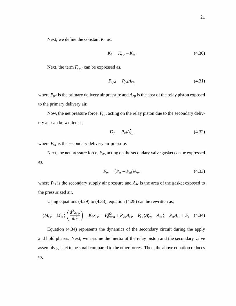
Next, wedefinetheconstantK4 as,
K4 � Krp � Ksv (4.30)
Next, thetermFrpd canbeexpressedas,
Frpd � PpdArp (4.31)
wherePpd is theprimarydeliveryair pressureandArp is theareaof therelaypistonexposed
to theprimarydeliveryair.
Now, thenetpressureforce,Fsp, actingon therelaypistondueto thesecondarydeliv-
eryair canbewrittenas,
Fsp � PsdA�rp (4.32)
wherePsd is thesecondarydeliveryair pressure.
Next, thenetpressureforce,Fsv, actingonthesecondaryvalvegasketcanbeexpressed
as,
Fsv � �Pss � Psd � Asv (4.33)
wherePss is thesecondarysupplyair pressureandAsv is theareaof thegasket exposedto
thepressurizedair.
Usingequations(4.29)to (4.33), equation(4.28)canberewrittenas,
�Mrp � Msv � d2xrp
dt2 � K4xrp � F p2reacn � PpdArp � Psd
�A�rp � Asv �� PssAsv � F3 (4.34)
Equation(4.34) representsthe dynamicsof the secondarycircuit during the apply
andhold phases.Next, we assumethe inertiaof the relaypistonandthesecondaryvalve
assemblygasketto besmallcomparedto theotherforces.Then,theaboveequationreduces
to,
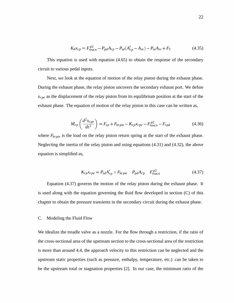
22
K4xrp � F p2reacn � PpdArp � Psd
�A�rp � Asv �� PssAsv � F3 (4.35)
This equationis usedwith equation(4.65) to obtain the responseof the secondary
circuit to variouspedalinputs.
Next, we look at theequationof motionof therelaypistonduringtheexhaustphase.
During theexhaustphase,therelaypistonuncoversthesecondaryexhaustport. We define
xrpe asthedisplacementof therelaypistonfrom its equilibrium positionat thestartof the
exhaustphase.Theequationof motionof therelaypistonin this casecanbewrittenas,
Mrpd2xrpe
dt2 � Fsp � Fkrpie � Krpxrpe � F p2reacn � Frpd (4.36)
whereFkrpie is the loadon the relaypistonreturnspringat thestartof theexhaustphase.
Neglectingthe inertiaof therelaypistonandusingequations(4.31)and(4.32), theabove
equationis simplifiedas,
Krpxrpe � PsdA�rp � Fkrpie � PpdArp � F p2
reacn (4.37)
Equation(4.37)governsthe motion of the relay pistonduring the exhaustphase.It
is usedalongwith the equationgoverningthe fluid flow developedin section(C) of this
chapterto obtainthepressuretransientsin thesecondarycircuit duringtheexhaustphase.
C. ModelingtheFluid Flow
We idealizethetreadlevalve asa nozzle.For theflow througha restriction, if theratio of
thecross-sectionalareaof theupstreamsectionto thecross-sectionalareaof therestriction
is morethanaround4.4, theapproachvelocity to this restrictioncanbeneglectedandthe
upstreamstaticproperties(suchaspressure,enthalpy, temperature, etc.) canbe taken to
be the upstreamtotal or stagnationproperties[2]. In our case,the minimum ratio of the

23
cross-sectionalareaof the supplychamberof the valve to the cross-sectionalareaof the
valveopening(therestrictionin ourcase)wasfoundout to bearound15.4.Also, thecross-
sectionalareaof thevalve openingdecreasesmonotonically to a minimumvalue. Hence,
we canconsiderthevalve openingasa nozzleandtake thestaticpropertiesin thesupply
chamberof the valve asthe stagnationpropertiesat the inlet sectionof the nozzle. The
flow throughthis idealizedvalve is assumedto beone-dimensional andisentropic.Further,
thefluid propertiesareassumedto beuniform at all sectionsin thenozzle.We assumeair
to behave like anidealgas.Fig. 6 shows thesimplifiedpneumaticsystemundertheabove
assumptions.
Fig. 6. Thesimplifiedpneumaticsystem
The energy equationfor isentropicflow of air throughthe nozzleunderthe above
assumptionscanbewrittenas[10],
h �12
u2 � ho (4.38)
whereho is thespecificstagnationenthalpy at theentrancesectionof thenozzle,h is the
specificstaticenthalpy at theexit sectionof thenozzleandu is thevelocityof air at theexit
sectionof thenozzle.

24
Sinceair is consideredto beanidealgas,its specificenthalpy at any point in theflow
regioncanbewrittenas,
h � cpT (4.39)
wherecp is thespecificheatof air at constantpressure(assumedto beaconstant)andT is
the local statictemperature of theair at thatpoint. Then,equation(4.38)canberewritten
as,
cpT �12
u2 � cpTo (4.40)
whereTo is thestagnationtemperatureof thecompressedair in thesupplychamber.
We have madetheassumptionthatair behaveslike anidealgas.For anidealgas,the
local staticpressureis a functiononly of its localdensity, i.e.,
P � P�ρ � (4.41)
whereP is thelocal staticpressureandρ is thelocaldensityof air.
Weusethefollowing “Ideal GasLaw” in theequationsbelow:
P�ρ � � ρRT (4.42)
whereR is thegasconstantfor air andT is thelocal statictemperature.
For isentropicflow of an idealgas,thestaticpressure,densityandstatictemperature
arerelatedby,Pργ � constant (4.43)
Pγ � 1
γ
T� constant (4.44)
25
whereγ is theratioof thespecificheats.Weassumethatthis ratio is aconstant.
γ � cp
cv(4.45)
wherecv is thespecificheatof air at constantvolume.
For anidealgas,thetwo specificheatsarerelatedby,
cp � cv � R (4.46)
Thus,from (4.45)and(4.46),
cp � γγ � 1
R
cv � 1γ � 1
R (4.47)
Usingequations(4.42)to (4.47), equation(4.40)canbesolvedfor thevelocity u as,
u � 2γγ � 1
Po
ρo1 � P
Po
γ � 1γ
12
(4.48)
Next, we choosethe brake chamberand the air hoseas the control volume under
consideration.We assumeall fluid propertiesin the control volumeto be uniform at any
instantof time. Weassumefrictionallossesin thehoseto benegligible. TheMachnumber
of theflow in thehosewasmeasuredat theentranceof thebrake chamber. Thefollowing
formula from [10] is usedto calculatethe Mach numberfrom the measurementsof the
staticandstagnationpressures.
M � 2γ � 1
Po
P
γ � 1γ
� 1
12
(4.49)
whereM is the local MachnumberandPo is the local stagnationpressure.Although the
26
above formula for theMachnumberdoesnot really hold for theproblemunderconsidera-
tion, we proceedto usethis approximation in thedevelopmentof this model. For various
testruns,thevalueof theMachnumberwasfoundnot to exceed0.2. Hence,we canne-
glecttheeffectsof compressibility of air for theflow throughthehose[24]. Applying mass
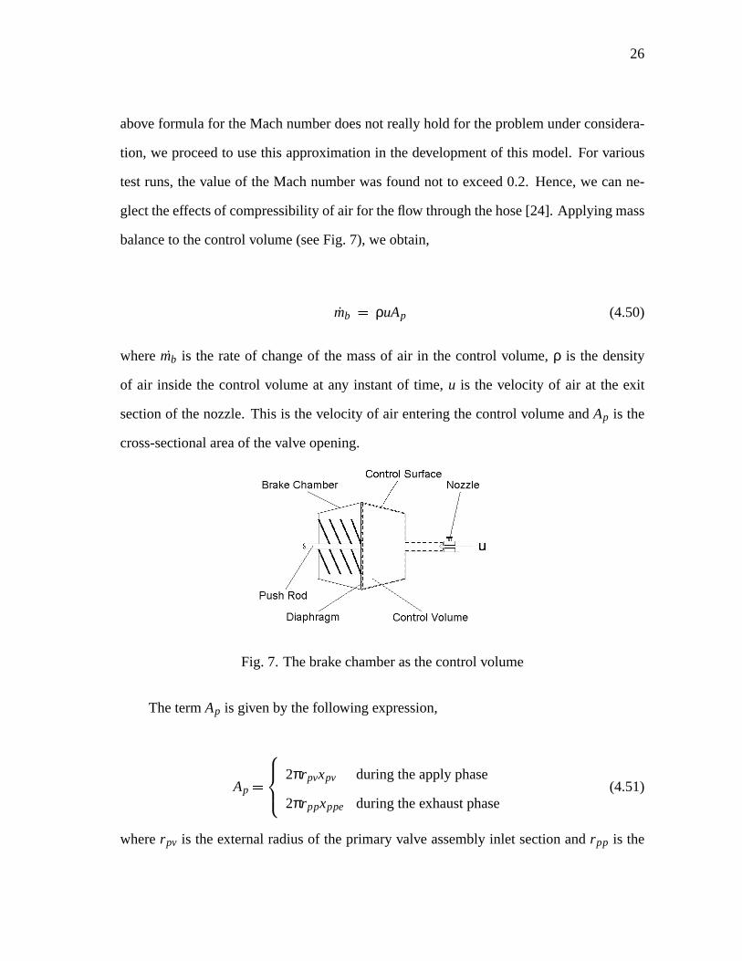
balanceto thecontrolvolume(seeFig. 7), weobtain,
mb � ρuAp (4.50)
wheremb is the rateof changeof the massof air in the control volume, ρ is the density
of air insidethe control volume at any instantof time, u is the velocity of air at the exit
sectionof thenozzle.This is thevelocity of air enteringthecontrolvolume andAp is the
cross-sectionalareaof thevalveopening.
Fig. 7. Thebrakechamberasthecontrolvolume
ThetermAp is givenby thefollowingexpression,
Ap �2πrpvxpv duringtheapplyphase
2πrppxppe duringtheexhaustphase(4.51)
whererpv is theexternalradiusof theprimary valve assemblyinlet sectionandrpp is the
27
externalradiusof theprimary pistonexhaustseat.
Next, let usconsiderthemassof air insidethecontrolvolume at any instantof time,
mb. Sincewe treatair asanidealgas,
mb � PbVb
RTb(4.52)
wherePb is the local static pressureinside the control volume, Vb is the volume of the
controlvolumeandTb is thelocalstatictemperatureinsidethecontrolvolumeatthatinstant
of time.
Differentiatingbothsidesof theaboveequationwith respectto time,weobtain,
mb � PbVb
RTb�
PbVb
RTb� PbVb
RT 2b
Tb (4.53)
Usingequation(4.44),equation(4.53)canbesimplifiedas,
mb � 1γ
PbVb
RTb�
PbVb
RTb(4.54)
Let usnow considerthevariationof thebrake chambervolumeasa functionof time
duringthebrake application.At thestartof theapplication,thebrake chamberdiaphragm
startsto move only after the required“push-out” pressureis reached[12]. This initial
increasein pressureis utili zed in overcomingthe pre-loadsof the brake chamberreturn
springandthereturnspringin thebrakedrum.As soonasthepush-outpressureis reached,
the brake chambervolume startsto increaseand as a result, the time rate of growth of
the brake chamberpressuredecreases.The brake chambervolume reachesits maximum
valuewhenthe brake padscontactthe drum. After this, the time rateof pressuregrowth
startsto increaseandthe subsequentgrowth of the brake chamberpressureis utili zedin
increasingthebrakeforce.Thesevariationsaretakeninto accountin ourmodelby varying
the expressionfor the brake chambervolumedependingon the phaseof operationof the

28
brake chamberdiaphragm. Thevolume of air insidethecontrol volume at any instantof
time canbewrittenas,
Vb �Vo1 if Pb � Pt
Vo1 � Abxb if 0 � xb � xbmax
Vo2 if xb � xbmax
(4.55)
whereVo1 is the initial volume of air in the control volume beforethe applicationof the
brake,Vo2 is the maximumvolumeof air in the control volume,Ab is the cross-sectional
areaof thebrakechamber, xb is thestrokeof thebrakechamberdiaphragm,i.e., thestroke
of thepushrod,xbmax is themaximumstrokeof thepushrodandPt is thepush-outpressure.
Usingtheaboveequation,equation(4.54)canbewrittenas,
mb �
Vo1
γRTbPb if Pb � Pt
Vb
γRTbPb �
PbAb
RTbxb if 0 � xb � xbmax
Vo2
γRTbPb if xb � xbmax
(4.56)
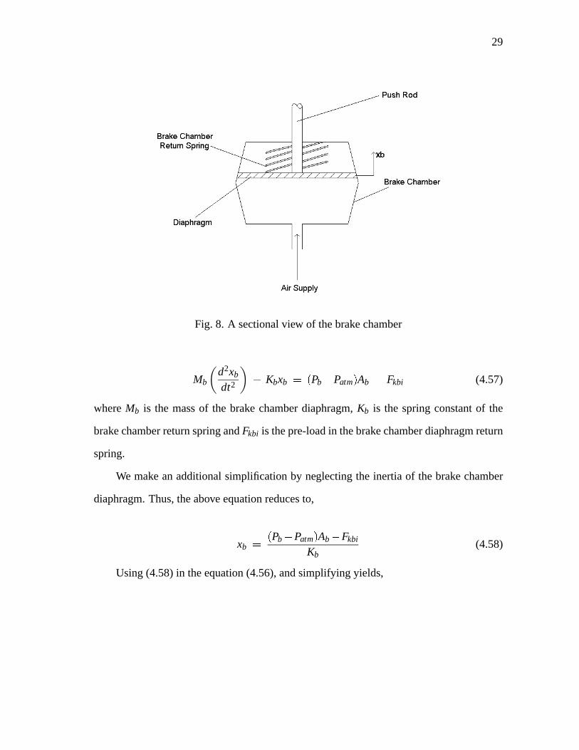
Let usnow considerthedynamicsof thebrakechamber(referto Fig. 8). Theequation
of motionof thebrakechamberdiaphragmcanbewrittenas(weneglectany friction in the
brakechamber),
29
Fig. 8. A sectionalview of thebrakechamber
Mbd2xb
dt2 � Kbxb � �Pb � Patm � Ab � Fkbi (4.57)
whereMb is the massof the brake chamberdiaphragm, Kb is the springconstantof the
brakechamberreturnspringandFkbi is thepre-loadin thebrakechamberdiaphragmreturn
spring.
We make anadditional simplificationby neglectingthe inertiaof thebrake chamber
diaphragm.Thus,theaboveequationreducesto,
xb ��Pb � Patm � Ab � Fkbi
Kb(4.58)
Using(4.58)in theequation(4.56),andsimplifyingyields,

30
mb �
Vo1
γRTbPb if Pb � Pt
Vb
γRTb�
PbA2b
RTbKbPb if 0 � xb � xbmax
Vo2
γRTbPb if xb � xbmax
(4.59)
Equation(4.48)gaveusarelationshipto calculatethevelocityof air at theexit section
of the nozzle. We modify this equationwith a discharge coefficient CD in orderto com-
pensatefor the lossesduring the flow. Due to the complexity involved in calibratingthe
valve to determinethevalueof the dischargecoefficient, we assumeda valueof 0.82for
CD asrecommendedin [2]. Also, we modify theequationsothat thedirection of theflow
is incorporated.
u � CD2γ
γ � 1Po
ρo1 � Pb
Po
γ � 1γ
12
sgn�Po � Pb � (4.60)
Thesignumfunctionusedin theaboveequationis definedas,
sgn�Po � Pb � : � Po � Pb�
Po � Pb� (4.61)
Thus,the signumfunction indicatesthe directionof flow dependingon the pressure
difference.During theapplyandthehold phases,Po is thesupplypressureandduringthe
exhaustphase,Po is theatmosphericpressure.
Now usingequations(4.42)and(4.60), equation(4.50)canbere-writtenas,

31
mb � Pb
RTbApCD
2γγ � 1
Po
ρo1 � Pb
Po
γ � 1γ
12
sgn�Po � Pb � (4.62)
When the pressureratio is lessthan the critical value, choked flow conditionsare
assumedandthemassflow rateis maximumthroughthenozzleunderthis condition.The
critical pressureratio is givenby,
Pb
Po cr� 2
γ � 1
γγ � 1
(4.63)
Now, comparingequations(4.59)and(4.62),weobtainthegoverning equationfor the
pressuretransientsin thebrake chamberfor thevariousphasesof themotionof thebrake
chamberdiaphragm.
ApCD
RTb
2γγ � 1
Po
ρo1 � Pb
Po
γ � 1γ
12
sgn�Po � Pb � Pb �
Vo1
γRTbPb if Pb � Pt
Vb
γRTb�
PbA2b
RTbKbPb if 0 � xb � xbmax
Vo2
γRTbPb if xb � xbmax
(4.64)
This is afirst ordernon-lineardifferentialequationin Pb. Next, wesimplify theabove
equationby usingequations(4.42)and(4.44)to obtainthefollowing equation,

32
ApCD2γ
γ � 11
RTo
Pb
Po
2γ
� Pb
Po
γ� 1γ
12
sgn�Po � Pb � Po �
Vo1Pγ � 1
γo
γRToPγ � 1
γb
Pb if Pb � Pt
VbPγ � 1
γo
γRToPγ � 1
γb
�P
1γ
b A2bP
γ � 1γ
o
RToKbPb if 0 � xb � xbmax
Vo2Pγ � 1
γo
γRToPγ � 1
γb
Pb if xb � xbmax
(4.65)
This is thegoverningequationfor thepressuretransientsin thebrakechamberduring
theapplyphasewith thetermPo beingthesupplypressure.Thecoefficientsof theabove
equationarenow functionsof Pb andAp andthis equationhasto besolvedwith theinitial
conditionthatat thestartof theapplyphase,Pb � Patm. At eachtimestepduringtheapply
phase,thevalueof thepressureobtainedfrom this equationis usedto determinethestage
of operationof thetwo circuitsthroughequations(4.15)and(4.35).
Usingequation(4.63),theexpressionon the left handsideof equation(4.65)canbe
writtenasthefollowing,

33
f�Pb � Ap � �
ApCDPo
2γ
γ � 1
1
RTo
Pb
Po
2γ
�Pb
Po
γ� 1γ
12
sgn�Po � Pb �
ifPb
Po
Pb
Po
cr
ApCDPo
2γ
γ � 1
1
RTo
2
γ � 1
2γ � 1
12
sgn�Po � Pb �
ifPb
Po�
Pb
Po
cr
(4.66)
where f�Pb � Ap � refersto theleft handsideof equation(4.65).
For theexhaustphase,thetermPo is takento betheatmosphericpressurePatm andthe
termTo is takento betheatmospherictemperature. Thegoverningdifferentialequationis
solved with the initial conditionthat at the startof the exhaustphase,the pressurein the
brakechamberis thesteadystatepressureattheendof theapplyphase.Thebrakechamber
volumeis themaximumatthestartof theexhaustphaseanddecreasesastheexhaustphase
progressesaccordingto thefollowing equation,
Vb �Vo2 if xbe � 0
Vo2 � Abxbe if 0 � xbe � xbmax
Vo1 if xbe � xbmax
(4.67)
wherexbe is thedisplacementof thebrakechamberdiaphragmfrom its equilibrium position

34
at thestartof theexhaustphase.
35
CHAPTERV
CORROBORATION OFTHE MODEL
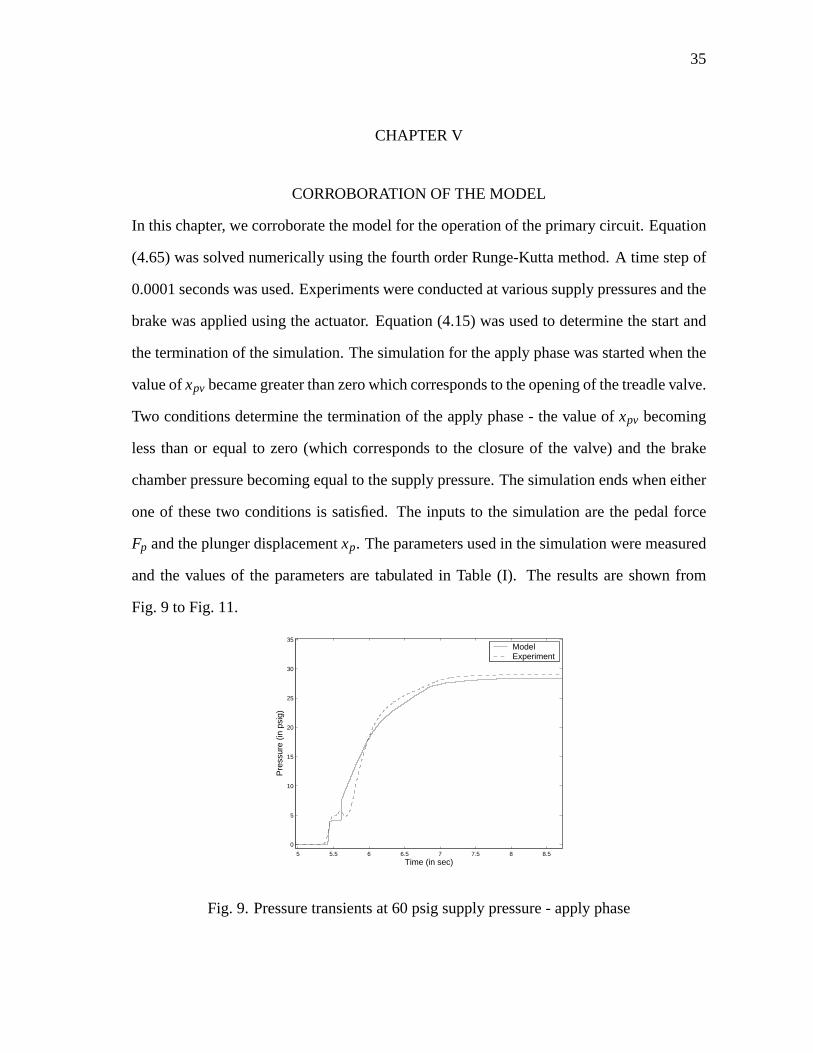
In thischapter, wecorroboratethemodelfor theoperationof theprimarycircuit. Equation
(4.65)wassolvednumerically usingthefourth orderRunge-Kutta method.A time stepof
0.0001secondswasused.Experimentswereconductedatvarioussupplypressuresandthe
brake wasappliedusingtheactuator. Equation(4.15)wasusedto determine thestartand
theterminationof thesimulation. Thesimulationfor theapplyphasewasstartedwhenthe
valueof xpv becamegreaterthanzerowhichcorrespondsto theopeningof thetreadlevalve.
Two conditionsdeterminethe termination of theapplyphase- thevalueof xpv becoming
lessthanor equalto zero(which correspondsto the closureof the valve) andthe brake
chamberpressurebecomingequalto thesupplypressure.Thesimulation endswheneither
oneof thesetwo conditions is satisfied.The inputsto the simulationarethe pedalforce
Fp andtheplungerdisplacementxp. Theparametersusedin thesimulationweremeasured
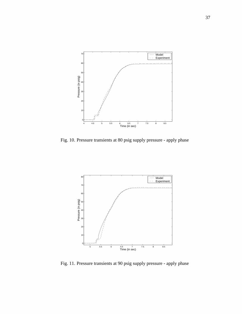
andthe valuesof the parametersare tabulatedin Table (I). The resultsareshown from
Fig. 9 to Fig. 11.
5 5.5 6 6.5 7 7.5 8 8.5
0
5
10
15
20
25
30
35
Time (in sec)
Pre
ssur
e (in
psi
g)
ModelExperiment
Fig. 9. Pressuretransientsat60psigsupplypressure- applyphase

36
TableI. Valuesof theparametersusedin thesimulation
Parameter Value Parameter Value
Apv 0.0002356m2 Apv1 0.0004184m2
App 0.002357m2 Ab 0.129m2
Arp 0.001985m2 A�rp 0.003141m2
Kb 1167.454N
mKss 2556.724
N
m
F1 -193.832N K2 8178.716N
m
L1 68.944N L2 6418.078N
m
xpt 0.00127m Patm 101.356KPa
rpv 0.01283m rpp 0.01232m
γ 1.4 Vo1 0.0001639m3
xbmax 0.0254m Fkbi 355.84N
R 287J
kgKTo 298K
CD 0.82
37
4 4.5 5 5.5 6 6.5 7 7.5 8 8.5
0
10
20
30
40
50
60
70
Time (in sec)
Pre
ssur
e (in
psi
g)
ModelExperiment
Fig. 10. Pressuretransientsat80psigsupplypressure- applyphase
5 5.5 6 6.5 7 7.5 8 8.5
0
10
20
30
40
50
60
70
80
Time (in sec)
Pre
ssur
e (in
psi
g)
ModelExperiment
Fig. 11. Pressuretransientsat90psigsupplypressure- applyphase

38
4 6 8 10 12 14
0
5
10
15
20
25
30
35
40
45
50
Time (in sec)
Pre
ssur
e (in
psi
g)
ModelExperiment
Fig. 12. Pressuretransientsat70psigsupplypressure- applyandexhaustphases
4 6 8 10 12 14
0
10
20
30
40
50
60
Time (in sec)
Pre
ssur
e (in
psi
g)
ModelExperiment
Fig. 13. Pressuretransientsat80psigsupplypressure- applyandexhaustphases

39
4 5 6 7 8 9 10 11 12 13
0
5
10
15
20
25
30
35
40
45
50
Time (in sec)
Pre
ssur
e (in
psi
g)
ModelExperiment
Fig. 14. Pressuretransientsat90psigsupplypressure- applyandexhaustphases
5 10 15 20 25 30
0
5
10
15
20
25
30
35
40
45
50
Time (in sec)
Pre
ssur
e (in
psi
g)
ModelExperiment
Fig. 15. Pressuretransientsat70psigsupplypressure- periodicapplication

40
Wecanobservefrom Fig. 9 to Fig. 11thatthemodelis ableto predictthestartandthe
endof thebrake applicationfor all thecases. Thesteadystatevalueof thebrake chamber
pressureis alsopredictedaccurately. We canalsoobserve that themodelis ableto follow
theinitial behavior of thepressuregrowth curvesincewedividedtheoperationof thebrake
chamberinto threedifferentphases.
Testswerealsoperformedfor a completecycle of brake application.Themodelwas
usedto simulateboth theapplyandtheexhaustphasesfor suchapplications.Theresults
areshown from Fig. 12 to Fig. 14. Finally, a testrun wasperformedwheretheapplyand
the exhaustphaseswereperiodically repeated.Resultsfrom sucha test run is shown in
Fig. 15.
41
CHAPTERVI
CONCLUDINGREMARKSAND FUTUREWORK
Fromtheabovefigures,it canbeseenthatthemodelwasableto predictthebeginningand
the endof eachbrake applicationaccurately. The steadystatevaluesarealsoaccurately
predictedby the model in all the cases. We observe that the model respondedwell to
varioussupplypressures.The modelalsopredictedthe start and the termination of the
exhaustphaseaccuratelyaswasevidentfrom Fig. 12 to Fig. 14. Fig. 15demonstratedthat
themodelrespondswell to periodicapplicationsof thebrakepedal.
With this modelof thepneumaticsubsystemof theair brake system,currentwork is
directedtowardsestimatingthestroke of thepushrod. An estimationschemeis beingde-
velopedthatwill estimatethepushrodstrokefrom measurementsof thepedaldisplacement
andthepedalforce. Experimentsarebeingperformedto measurethepushrod stroke dur-
ing thebrakeapplicationandtheresultsfrom theestimationschemewouldbecorroborated
with thesemeasurements.
42
REFERENCES
[1] T. Acarman,U. Ozguner, C. Hatipoglu andA. M. Igusky, “Pneumaticbrake system
modeling for systemsanalysis,” SAEPaper2000-01-3414,2000.
[2] B. W. Anderson,The AnalysisandDesignof PneumaticSystems, New York: John
Wiley & Sons,Inc., 1967.
[3] R. M. Braswell,J. F. Broder, P. J. Fisher, R. D. Flesher, D. Foster, S. Gooch,K. F.
Johnson,H. T. Pannella,R. L. Rak,G. H. Rood,J.Salas,C. O. Summer, V. Suskiand
J. Thrift, “Tomorrow’s trucks: A progressreview andreappraisalof future needs,”
SAEPaper932975, 1993.
[4] L. C. Buckman,“Commercialvehicle braking systems:Air brakes, ABS and be-
yond,” paperpresentedat International Truck & BusMeeting& Exposition,Society
of AutomotiveEngineers,Indianapolis,November1998.
[5] M. Druzhinina,L. MoklegaardandA. G. Stefanopoulou,“Identificationandintegra-
tion of commercialheavy vehicleretarders,” ResearchReportUCB-ITS-PRR-2002-
14, California PATH Program,Universityof California,Berkeley, California, March
2002.
[6] J. C. Gerdesand J. K. Hedrick, “Brake systemmodeling for simulation and con-
trol,” Journalof DynamicSystems,MeasurementandControl, vol. 121,pp.496–503,
September1999.
[7] “Inspection statistics,” http://www.ntsb.gov/publictn/2002/SR0201.pdf, 2003 [Ac-
cessedJanuary2003].
43
[8] L. Johnson,P. S. FancherandT. D. Gillespie,“An empiricalmodel for the predic-
tion of the torqueoutputof commercialvehicleair brakes,” ResearchReportUM-
HSRI-78-53,HighwaySafetyResearchInstitute,Universityof Michigan,Ann Arbor,
Michigan,December1978.
[9] Y. Khan, P. Kulkarni and K. Youcef-Toumi, “Modeling, experimentation and sim-
ulation of a brake apply system,” Journalof Dynamic Systems,Measurementand
Control, vol. 116,pp.111–122, March1994.
[10] H. W. Liepmannand A. Roshko, Elementsof Gasdynamics, Mineola, New York:
DoverPublications,Inc., 2001.
[11] D. Middleton andJ. Rowe, “Feasibility of standardizeddiagnosticdevice for main-
tenanceand inspectionof commercialmotor vehicles,” TransportationResearch
Record, vol. 1560,pp.48–56,1996.
[12] R. J. Morse, “Brake systemperformanceat low operatingpressures,” SAE Paper
700512,1970.
[13] K. Newton,W. SteedsandT. K. Garrett,TheMotor Vehicle, 12thedition,Warrendale,
Pennsylvania:Societyof AutomotiveEngineers,Inc., 1996.
[14] A. V. OppenheimandR. W. Schafer, Digital SignalProcessing, Englewood Cliffs,
New Jersey: Prentice-Hall,Inc., 1975.
[15] T. M. Post,P. S. FancherandJ. E. Bernard,“Torquecharacteristicsof commercial
vehiclebrakes,” SAEPaper750210,1975.
[16] R. W. Radlinski,“Braking performanceof heavy U.S.vehicles,” SAE Paper870492,
1987.

44
[17] R. W. Radlinski,“Heavy vehiclebraking- U.S.versusEurope,” SAE Paper892504,
1989.
[18] P. G. ReinhallandR. R. Scheibe,“Developmentof an intelligent air brake warning
systemfor commercialvehicles,” ResearchReportITS-13, IDEA Program,Trans-
portationResearchBoard,NationalResearchCouncil,Washington,D.C.,May 1996.
[19] S.J.Shaffer andG. H. Alexander, “Commercialvehiclebrake testing- Part1: Visual
inspectionversusperformance-basedtest,” SAEPaper952671,1995.
[20] S. J. Shaffer andG. H. Alexander, “Commercialvehiclebrake testing- Part 2: Pre-
liminaryresultsof performance-basedtestprogram,” SAEPaper952672,1995.
[21] G. W. Stearns,“FMVSS 121- Air brake systems:How it affectstractor-trailer com-
binations,” AutomotiveEngineering, vol. 81,pp.37–48,September1973.
[22] “TIFA statistics,” http://www.umtri.umich.edu/cnts/doc/TIFA1999.pdf, 2003 [Ac-
cessedJanuary2003].
[23] S. F. Williams andR. R. Knipling, “Automaticslackadjustersfor heavy vehicleair
brakesystems,” ResearchReportDOT HS807724,NationalHighwayTraffic Safety
Administration,Washington,D.C.,February1991.
[24] M. J. Zucrow andJ. D. Hoffman, GasDynamics, vol. 1, New York: JohnWiley &
Sons,Inc., 1976.

45
VITA
ShankarCoimbatore Subramanianwasborn in thecity of Coimbatore, locatedin the
Indianstateof Tamilnadu.He wasbrought up in thecity of Chennaiandcompletedhigh
schoolthere.HeobtainedhisBachelorof Engineeringin mechanicalengineeringfrom the
Universityof Allahabadin May 2000.He joinedtheMechanicalEngineeringDepartment
at TexasA&M University in August2000.He graduatedwith a Masterof Sciencedegree
in mechanicalengineeringfrom TexasA&M University in May 2003. ShankarCoimbat-
ore Subramanianmay be contactedthroughProf. K. R. Rajagopalat the Departmentof
MechanicalEngineering,TexasA&M University, CollegeStation,TX 77843-3123.