modelling and simulation of three phase bldc motor … · modelling and simulation of three phase...
TRANSCRIPT

International Journal Of Electrical, Electronics And Data Communication, ISSN: 2320-2084 Volume-5, Issue-7, Jul.-2017
Modelling and Simulation of three Phase BLDC Motor for Electric Braking using Matlab/Simulink
48
MODELLING AND SIMULATION OF THREE PHASE BLDC MOTOR FOR ELECTRIC BRAKING USING MATLAB/SIMULINK
1SHIRISH VASANTRAO GADEWAR,2A. M. JAIN
Student, Associate Professor, Electrical Engineering Department K.K.W.I.E.E.R Nasik, India
E-mail :[email protected],[email protected]
Abstract - Brushless motors are mostly used in pump and fan applications. They have the capability of developing high torque with good speed response. The Brushless DC motors possess their high efficiency, high torque, low maintenance, less noise and low volume. Due to their usage, many advances are taking place in the field of automobiles in general and electric vehicles in particular. To have an effective control over the electric vehicles it is desirable to have control over starting, running and braking of a BLDC drive. In this paper, the three-phase brushless DC motor model is designed for running and braking mode operation under trapezoidal back electromotive force using a PI controller. Also, parameters like Back EMF, current, speed and torque are evaluated for the designed models of BLDC motor. Keywords - Brushless DC motor, Trapezoidal back EMF, PI controller, Regenerative braking, Energy regeneration. I. INTRODUCTION The AC motors are generally less expensive, rugged, can operate in both motoring and generating mode, and have low maintenance. However, one of their drawbacks is the need for a commutator and brushes that make the motor to operate normally are subjected to wear and tear and require maintenance. That’s why the Permanent Magnet Machines are developed which are able to overcome all of the above limitations and to provide the requirements of a well variable speed drive. [1] A Brushless DC Motor is also known as a BLDC Motor, is a synchronous electric motor powered by a direct current. The Brushless DC Motor does not operate using brushes; rather it operates with a controller via electronic commutation. The permanent magnet machines have the high torque to size ratio. They possess very good dynamic characteristics. The BLDC motor is fed with voltages having rectangular shaped waveform and the windings are distributed so as to produce trapezoidal back e.m.f. In Brushless DC Motor, the Hall Effect Sensors are used to directly identify the position of the rotor.[2]Since the issues concerning cost, volume, and reliability are important when developing an EV, this paper designs a single-stage bi-directional DC/AC converter based on a general full-bridge inverter with PI control technique. The proposed design uses different switching strategies without any additional power switches or bulky passive components. [2]This paper is organized as follows: BLDC motor construction and principle of operation in section II, Mathematical modeling of BLDC in section III, then the paper describe the principle behind electrical braking in section IV, later the PI control system is described in section V, MATLAB model along with the results are explained in section VI-VII, section VIII concludes the paper.
II. CONSTRUCTION AND OPERATING PRINCIPLE BLDC motors are more or less similar to the synchronous motor. This indicates the magnetic field produced by the stator and the magnetic field produced by the rotor rotate at the same frequency. [3] Figure 1 shows the constructional view of BLDC. BLDC motor is built with a permanent magnet rotor and winding is placed on stator poles.
Fig.1. Stator, Rotor, and Hall sensors of PMBLDC motor
A. Stator The stator of a BLDC motor is made of stacked steel laminations with windings arranged in the slots that are cut along the inner periphery. Most BLDC motors have three stator windings linked in the star. Each of these windings is assembled along with various coils interconnected to drive a winding. The coils are kept in the slots and they are interconnected to form a winding. Each of these windings is distributed over the stator peripheral area to form even numbers of poles. B. Rotor The rotor is formed from the permanent magnet and can alter from two to eight pole pairs with alternate North and South poles. A suitable magnetic material is chosen to form the motor depending upon the required field density in the rotor. At present, rare earth alloy Magnets are used to make permanent magnets.
International Journal Of Electrical, Electronics And Data Communication, ISSN: 2320-2084 Volume-5, Issue-7, Jul.-2017
Modelling and Simulation of three Phase BLDC Motor for Electric Braking using Matlab/Simulink
49
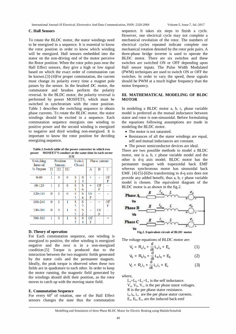
C. Hall Sensors To rotate the BLDC motor, the stator windings need to be energized in a sequence. It is essential to know the rotor position in order to know which winding will be energized. Hall sensors embedded into the stator on the non-driving end of the motor perceive the Rotor position. When the rotor poles pass near the Hall Effect sensors, they give a high or low signal based on which the exact order of commutation can be known.[3]-[4]For proper commutation, the current must change its polarity every time a magnet pole passes by the sensor. In the brushed DC motor, the commutator and brushes perform the polarity reversal. In the BLDC motor, the polarity reversal is performed by power MOSFETS, which must be switched in synchronism with the rotor position. Table 1 describes the switching sequence to obtain phase currents. To rotate the BLDC motor, the stator windings should be excited in a sequence. Each commutation sequence energizes one winding to positive power and the second winding is energized to negative and third winding non-energized. It is important to know the rotor position for deciding energizing sequence.
Table.1.Switch table of the power converter in which two power MOSFET’S conduct at the same time in each sector
[13]
D. Theory of operation For Each commutation sequence, one winding is energized to positive, the other winding is energized negative and the next is in a non-energized condition.[5] Torque is produced due to the interaction between the two magnetic fields generated by the stator coils and the permanent magnets. Ideally, the peak torque is observed when these two fields are in quadrature to each other. In order to keep the motor running, the magnetic field generated by the windings should shift their position, as the rotor moves to catch up with the moving stator field. E. Commutation Sequence For every 600 of rotation, one of the Hall Effect sensors changes the state thus the commutation
sequence. It takes six steps to finish a cycle. However, one electrical cycle may not complete a mechanical revolution of the rotor. The numbers of electrical cycles repeated indicate complete one mechanical rotation denoted by the rotor pole pairs. A three-phase bridge inverter is used to operate the BLDC motor. There are six switches and these switches are switched ON or OFF depending upon Hall sensor inputs. The Pulse Width Modulated (PWM) techniques are used to switch ON or OFF the switches. In order to vary the speed, these signals should be PWM at a much higher frequency than the motor frequency. III. MATHEMATICAL MODELING OF BLDC MOTOR In modeling a BLDC motor a, b, c, phase variable model is preferred as the mutual inductance between stator and rotor is non-sinusoidal. Before formulating the equations following assumptions are made in modeling the BLDC motor. The motor is not saturated. Resistances of all the stator windings are equal,
self and mutual inductances are constant. The power semiconductor devices are ideal.
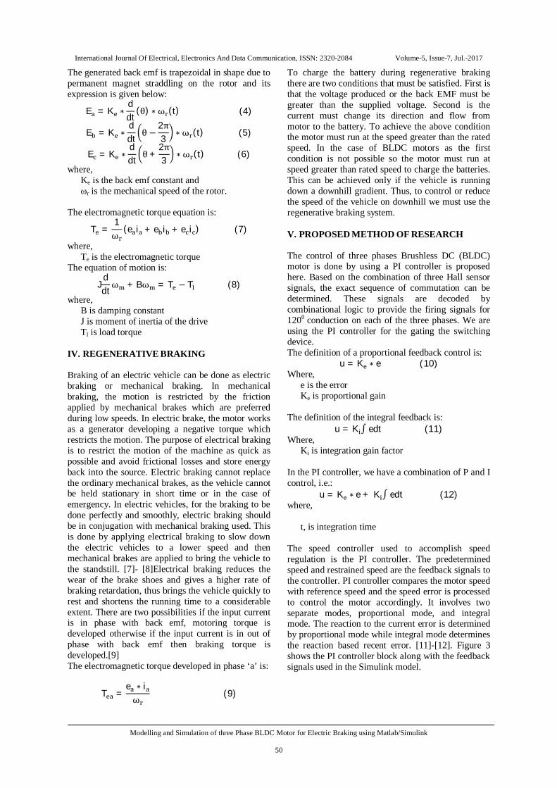
There are two possible methods to model a BLDC motor, one is a, b, c phase variable model and the other is d-q axis model. BLDC motor has the permanent magnet with trapezoidal back EMF whereas synchronous motor has sinusoidal back EMF. [4]-[5]-[6]So transforming to d-q axis does not provide any added benefit, thus a, b, c phase variable model is chosen. The equivalent diagram of the BLDC motor is as shown in the fig.2.
Fig.2. Equivalent circuit of BLDC motor
The voltage equations of BLDC motor are:
V = R i +ddt L i + E (1)
V = R i +ddt L i + E (2)
V = R i +ddt L i + E (3)
where,
La=Lb =Lc=L, is the self inductance. Va, Vb, Vc, is the per phase stator voltages. R is the per phase stator resistance. ia, ib, ic, are the per phase stator currents. Ea, Eb, Ec, are the induced back-emf
International Journal Of Electrical, Electronics And Data Communication, ISSN: 2320-2084 Volume-5, Issue-7, Jul.-2017
Modelling and Simulation of three Phase BLDC Motor for Electric Braking using Matlab/Simulink
50
The generated back emf is trapezoidal in shape due to permanent magnet straddling on the rotor and its expression is given below:
E = K ∗ddt
(θ) ∗ ω (t) (4)
E = K ∗ddt θ −
2π3 ∗ ω (t) (5)
E = K ∗ddt θ+
2π3 ∗ ω (t) (6)
where, Ke is the back emf constant and ωr is the mechanical speed of the rotor.
The electromagnetic torque equation is:
T =1ω
(e i + e i + e i ) (7)
where, Te is the electromagnetic torque
The equation of motion is:
Jddtω + Bω = T − T (8)
where, B is damping constant J is moment of inertia of the drive Tl is load torque
IV. REGENERATIVE BRAKING Braking of an electric vehicle can be done as electric braking or mechanical braking. In mechanical braking, the motion is restricted by the friction applied by mechanical brakes which are preferred during low speeds. In electric brake, the motor works as a generator developing a negative torque which restricts the motion. The purpose of electrical braking is to restrict the motion of the machine as quick as possible and avoid frictional losses and store energy back into the source. Electric braking cannot replace the ordinary mechanical brakes, as the vehicle cannot be held stationary in short time or in the case of emergency. In electric vehicles, for the braking to be done perfectly and smoothly, electric braking should be in conjugation with mechanical braking used. This is done by applying electrical braking to slow down the electric vehicles to a lower speed and then mechanical brakes are applied to bring the vehicle to the standstill. [7]- [8]Electrical braking reduces the wear of the brake shoes and gives a higher rate of braking retardation, thus brings the vehicle quickly to rest and shortens the running time to a considerable extent. There are two possibilities if the input current is in phase with back emf, motoring torque is developed otherwise if the input current is in out of phase with back emf then braking torque is developed.[9] The electromagnetic torque developed in phase ‘a’ is:
T =e ∗ iω (9)
To charge the battery during regenerative braking there are two conditions that must be satisfied. First is that the voltage produced or the back EMF must be greater than the supplied voltage. Second is the current must change its direction and flow from motor to the battery. To achieve the above condition the motor must run at the speed greater than the rated speed. In the case of BLDC motors as the first condition is not possible so the motor must run at speed greater than rated speed to charge the batteries. This can be achieved only if the vehicle is running down a downhill gradient. Thus, to control or reduce the speed of the vehicle on downhill we must use the regenerative braking system. V. PROPOSED METHOD OF RESEARCH The control of three phases Brushless DC (BLDC) motor is done by using a PI controller is proposed here. Based on the combination of three Hall sensor signals, the exact sequence of commutation can be determined. These signals are decoded by combinational logic to provide the firing signals for 1200 conduction on each of the three phases. We are using the PI controller for the gating the switching device. The definition of a proportional feedback control is:
u = K ∗ e (10) Where,
e is the error Ke is proportional gain
The definition of the integral feedback is:
u = K ∫ edt (11) Where,
Ki is integration gain factor In the PI controller, we have a combination of P and I control, i.e.:
u = K ∗ e + K ∫ edt (12) where,
t, is integration time
The speed controller used to accomplish speed regulation is the PI controller. The predetermined speed and restrained speed are the feedback signals to the controller. PI controller compares the motor speed with reference speed and the speed error is processed to control the motor accordingly. It involves two separate modes, proportional mode, and integral mode. The reaction to the current error is determined by proportional mode while integral mode determines the reaction based recent error. [11]-[12]. Figure 3 shows the PI controller block along with the feedback signals used in the Simulink model.
International Journal Of Electrical, Electronics And Data Communication, ISSN: 2320-2084 Volume-5, Issue-7, Jul.-2017
Modelling and Simulation of three Phase BLDC Motor for Electric Braking using Matlab/Simulink
51
Fig.3. PI controller and feedback signals
The sensitivity of controller and speed overshoot is controlled by varying proportional gain and the increase of integral gain will allow the motor speed to catch up with the reference speed. The proportional and integral gain must be varied within the limits otherwise it causes instability and the controller becomes insensitive. Too high gains may also result in saturation of the system. The Ke and Ki values of the controller are resolute by trial and error method. VI. SIMULINK MODEL Figure 4 shows the main model of the three phases BLDC motor which is designed in Matlab/Simulink environment in accordance with a mathematical model derived previously.
Fig.4. Main Simulink model of BLDC Motor.
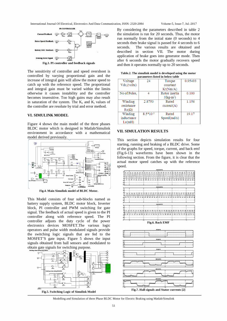
This Model consists of four sub-blocks named as battery supply system, BLDC motor block, Inverter block, PI controller and PWM switching for gate signal. The feedback of actual speed is given to the PI controller along with reference speed. The PI controller adjusts the duty cycle of the power electronics devices MOSFET.The various logic operators and pulse width modulated signals provide the switching logic signals that are fed to the MOSFET’S gate input. Figure 5 shows the input signals obtained from hall sensors and modulated to obtain gate signals for switching purpose.
Fig.5. Switching Logic of Simulink Model
By considering the parameters described in table 2 the simulation is run for 20 seconds. Thus, the motor run normally from the initial state (0 seconds) to 4 seconds then brake signal is passed for 4 seconds to 6 seconds. The various results are obtained and described in section VII. The motor during application of brake goes into generator mode. Then after 6 seconds the motor gradually recovers speed and then it operates normally up to 20 seconds.
Table.2. The simulink model is developed using the motor parameters listed in below table
VII. SIMULATION RESULTS This section depicts simulation results for four starting, running and braking of a BLDC drive. Some of the graphs for speed, torque, current, and back emf (Fig.6-13) waveforms have been shown in the following section. From the figure, it is clear that the actual motor speed catches up with the reference speed.
Fig.6. Back EMF
Fig.7. Hall signals and Stator currents [2]
International Journal Of Electrical, Electronics And Data Communication, ISSN: 2320-2084 Volume-5, Issue-7, Jul.-2017
Modelling and Simulation of three Phase BLDC Motor for Electric Braking using Matlab/Simulink
52
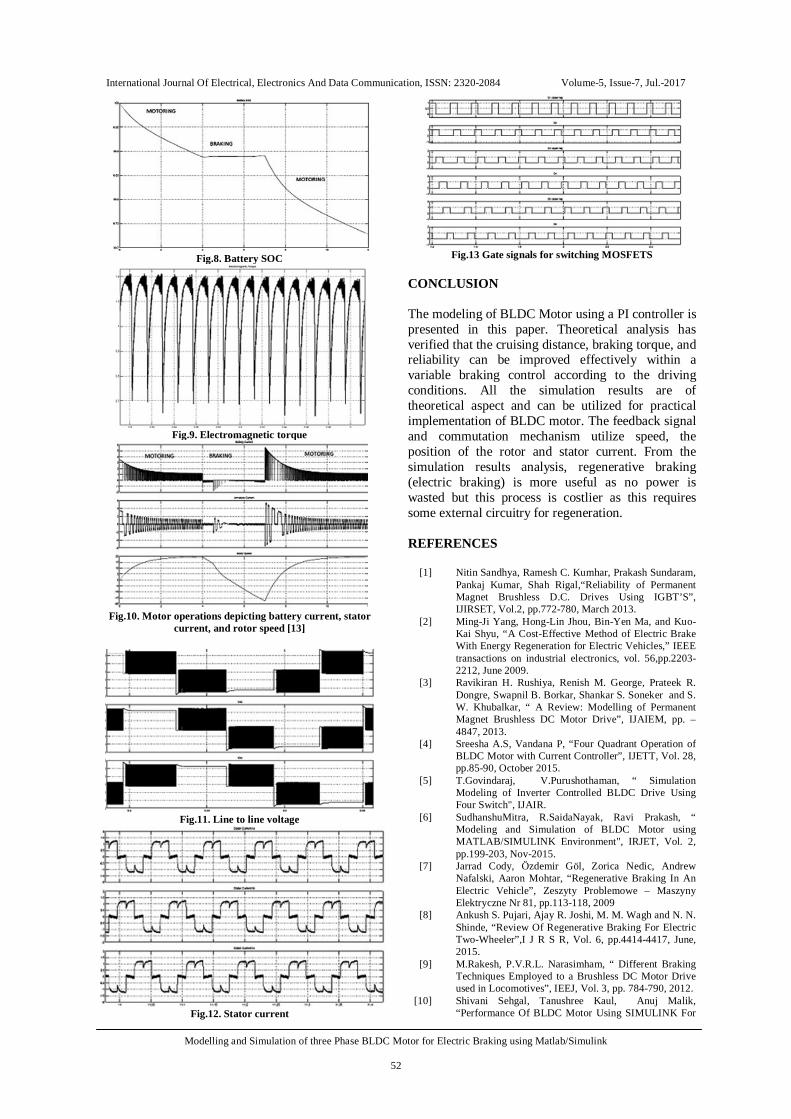
Fig.8. Battery SOC
Fig.9. Electromagnetic torque
Fig.10. Motor operations depicting battery current, stator
current, and rotor speed [13]
Fig.11. Line to line voltage
Fig.12. Stator current
Fig.13 Gate signals for switching MOSFETS
CONCLUSION The modeling of BLDC Motor using a PI controller is presented in this paper. Theoretical analysis has verified that the cruising distance, braking torque, and reliability can be improved effectively within a variable braking control according to the driving conditions. All the simulation results are of theoretical aspect and can be utilized for practical implementation of BLDC motor. The feedback signal and commutation mechanism utilize speed, the position of the rotor and stator current. From the simulation results analysis, regenerative braking (electric braking) is more useful as no power is wasted but this process is costlier as this requires some external circuitry for regeneration. REFERENCES
[1] Nitin Sandhya, Ramesh C. Kumhar, Prakash Sundaram,
Pankaj Kumar, Shah Rigal,“Reliability of Permanent Magnet Brushless D.C. Drives Using IGBT’S”, IJIRSET, Vol.2, pp.772-780, March 2013.
[2] Ming-Ji Yang, Hong-Lin Jhou, Bin-Yen Ma, and Kuo-Kai Shyu, “A Cost-Effective Method of Electric Brake With Energy Regeneration for Electric Vehicles,” IEEE transactions on industrial electronics, vol. 56,pp.2203-2212, June 2009.
[3] Ravikiran H. Rushiya, Renish M. George, Prateek R. Dongre, Swapnil B. Borkar, Shankar S. Soneker and S. W. Khubalkar, “ A Review: Modelling of Permanent Magnet Brushless DC Motor Drive”, IJAIEM, pp. – 4847, 2013.
[4] Sreesha A.S, Vandana P, “Four Quadrant Operation of BLDC Motor with Current Controller”, IJETT, Vol. 28, pp.85-90, October 2015.
[5] T.Govindaraj, V.Purushothaman, “ Simulation Modeling of Inverter Controlled BLDC Drive Using Four Switch", IJAIR.
[6] SudhanshuMitra, R.SaidaNayak, Ravi Prakash, “ Modeling and Simulation of BLDC Motor using MATLAB/SIMULINK Environment", IRJET, Vol. 2, pp.199-203, Nov-2015.
[7] Jarrad Cody, Özdemir Göl, Zorica Nedic, Andrew Nafalski, Aaron Mohtar, “Regenerative Braking In An Electric Vehicle”, Zeszyty Problemowe – Maszyny Elektryczne Nr 81, pp.113-118, 2009
[8] Ankush S. Pujari, Ajay R. Joshi, M. M. Wagh and N. N. Shinde, “Review Of Regenerative Braking For Electric Two-Wheeler”,I J R S R, Vol. 6, pp.4414-4417, June, 2015.
[9] M.Rakesh, P.V.R.L. Narasimham, “ Different Braking Techniques Employed to a Brushless DC Motor Drive used in Locomotives”, IEEJ, Vol. 3, pp. 784-790, 2012.
[10] Shivani Sehgal, Tanushree Kaul, Anuj Malik, “Performance Of BLDC Motor Using SIMULINK For
International Journal Of Electrical, Electronics And Data Communication, ISSN: 2320-2084 Volume-5, Issue-7, Jul.-2017
Modelling and Simulation of three Phase BLDC Motor for Electric Braking using Matlab/Simulink
53
Torque And Speed Analysis”, IJERT, Vol. 2, pp.819-822, July 2013.
[11] G.Premkumar, “Digital Control of BLDC Motor Using Hall Sensor”, IJECSCSE, Vol. 3, pp.8-12, 2012.
[12] S Ragu, “Simulation of Speed Control of Brushless DC Motor for four Quadrant Operation”, IJRASET, Vol. 2, pp.167-174, December 2014.
[13] Cheng-Hu Chen, Wen-Chun Chi, and Ming-Yang Cheng, “Regenerative Braking Control for Light Electric Vehicles”, IEEE PEDS, Vol. -1-4577-0001-9, pp.631-636, Dec, 2011.
[14] Bo Long, Shin Teak Lim, Ji Hyoung Ryu and Kil To Chong, “Energy-Regenerative Braking Control of Electric Vehicles Using Three-Phase Brushless Direct-Current Motors”, Energies, journal, Vol.7, pp. 99-114, Dec, 2013.
[15] Neeraj. M. K, Capt. L. Sanjeev Kumar, Shri Harsha J, “Three Phase Voltage Source Inverter for Front End Rectifier Fed to Ac-Motor Drive Using Matlab”, IJESIT, Vol 4, pp.221-226, May 2015.
[16] Binggang Cao, Zhifeng Bai, Wei Zhang, “Research on Control for Regenerative Braking of Electric Vehicle”, IEEE, Vol. 6, pp.92-97, 2005.