modelling guideline and sample modelling using scl...modelling guideline version 1.0 dke working...
TRANSCRIPT

Modelling Guideline__________________________________ ____ Version 1.0
DKE Working Group 952.0.1 Page 1 of 85
ArbeitsKreis 952.0.1:
Modelling Guideline and Sample Modelling using SCL
Version 1.0

Modelling Guideline Version 1.0
DKE Working Group 952.0.1 Page 2 of 85
Table of Contents 1 Introduction.................................................................................................................... 3
2 Modelling guidelines of DKE working group 952.0.1 ...................................................... 5
2.1 General modelling rules according to IEC 61850 ................................................... 5 2.2 Special rules for the modelling by DKE working group 952.0.1 .............................. 7
3 Documentation of the SCL-based sample modelling...................................................... 8
3.1 Substation structure and topology mapping in SCL................................................ 8 3.2 Type library ...........................................................................................................11 3.3 Product-independent system specification ............................................................53 3.4 Product mapping to actual IED structures .............................................................76
4 Appendix Modelling guidelines of DKE GAK 952.0.15 ..................................................80
4.1 Introduction ...........................................................................................................80 4.2 General Notes.......................................................................................................80 4.3 Rules for modelling data .......................................................................................81 4.4 Further modifications to the GAK15 modelling ......................................................85
5 Literature ......................................................................................................................85
Modelling Guideline Version 1.0
DKE Working Group 952.0.1 Page 3 of 85
1 Introduction This document describes the detailed specifications for the sample modelling of a reference substation in the form of a modelling guideline based on SCL (Substation Configuration description Language). This is based exclusively on edition 1 of IEC 61850. The only exception is that the elements “function” and “subfunction” are also assigned to voltage levels and bays. This is not permissible in edition 1 but was deemed necessary by working group 952.0.1 for the complete functional modelling of the substation. This expansion will also become normative in edition 2 of the IEC 61850.
The determinations in section 2 amend the modelling guidelines of DKE GAK 952.0.15 (part A to D, version 1.0 dated 10th February 2006) and update them by taking more recent knowledge into account. In this context, it has to be differentiated between general modelling rules (see section 2) and such rules defined specifically for the sample modelling performed by DKE AK 952.0.1 (see section 0).
Section 3 documents the sample substation modelled in SCL according to the rules described. This substation was basically adopted by GAK 952.0.15, and it does not claim to be complete or present secured substation functionality. It merely serves to illustrate the basic procedure for modelling information according to IEC 61850.
The process of engineering the substation documented in section 3 is carried out using a manufacturer-independent tool and comprises the following steps from 5 on:
I. Section 3:
Project planning of the primary system including a planned process link for the secondary equipment with assignment of the template classes “InClass” which are not yet further specified. This step serves to determine the scope of the system and generate a first .ssd file.
II. Section 3.2:
Typed definition of the LNs, DOs and DAs. During initial type definition this serves to create the type library, unless it already exists and an existing library is used.
III. Section 0:
Assigning the typed information objects to the system and determining the entire scope of information. “InType” is assigned here. The prefix and the instance numbers are not used since they are reserved for the product-related view. The hierarchical information modelling is instead accomplished in a functional perspective (“functional naming”) using the elements “Equipment” and “Subequipment” for primary equipment and “Function” and “Subfunction” for the functions.
The product-related structure of the control system is therefore still open in this phase of the engineering process so that this step results in an .ssd file including the information types (“data type templates”). It can be used for the solution-independent tendering phase.
The product-independent system specification generated in engineering step III with the typed information scope of the sample substation can be
Modelling Guideline Version 1.0
DKE Working Group 952.0.1 Page 4 of 85
downloaded 1 as .ssd file. Although the project engineering of working group 952.0.1 was carried out using a manufacturer-independent engineering tool, all private data (e.g. graphic elements) have been deleted from this file and can be opened using an XML browser.
IV. Section 3.4:
Complete information modelling including the system structure Here, .icd files are generated based on the functional specifications, or manufacturer-specific .icd files are imported and their product-related view (“product naming”) is adjusted or clearly assigned to the function-related view (“functional naming”). As a result of this step we obtain the .scd file. The .icd files tailored to the project for each device can be extracted from the .scd file’s IED section. They represent the information modelling related to the project.
The result of engineering step IV at the example of a bay of the sample substation can also be downloaded1 as .scd. file.
V. Datasets, communication structure and services have not yet been determined since they depend on the actual IED structures. Guidelines and recommendations in this context will be given when the work has further progressed.
In section 4 the modelling guidelines of DKE GAK 952.0.15 are appended and cross-references are given to the guidelines of working group 952.0.1 which are further developed in this document.
1 Note for users of the Substation Configuration Tool (SCT):
The private elements have been removed from the SCL data published on the DKE server. Therefore, they can not be read using the SCT. The unabridged data can be downloaded at www.fh-dortmund.de/sct.
Modelling Guideline Version 1.0
DKE Working Group 952.0.1 Page 5 of 85
2 Modelling guidelines of DKE working group 952.0.1
2.1 General modelling rules according to IEC 61850
The following rules and recommendations are independent of the actual sample modelling of DKE working group 952.0.1. They concern the general application of the IEC 61850 standard.
2.1.1 Connecting the primary equipment
Basically, all LNs relating to the primary equipment (X..., T..., Y...) have to be modelled. They should at least be modelled to the secondary equipment connection (relation between SSD and SCD) even if their data is not used over a bus. For instance, XSWI is always used for the modelling of isolators regardless of whether the detection or control is conventional or unconventional. The model thus becomes independent of the location and type of processing.
Processing functions are always located in the corresponding control LNs. For instance, the suppression of the intermediate position is implemented in CSWI. The unprocessed switch position can then be accessed via XSWI.
The logical nodes for current (TCTR) and voltage transformers (TVTR) are modelled multiple times during IED structuring in logical devices.
2.1.2 Transformer modelling
Each conductor usually receives its own LN. In the system specification phase, the phase structuring is accomplished via the element “Subequipment“.
The alternative representation of the three phases by duplicating the data object Vol or Amp is excluded.
2.1.3 Assigning values to instances
For the structure and content of the modelling to remain valid independently of one another, the value assignments, e.g. command output time for CB, protection setting values, are made only during instancing and not during type definition. Different output times or parameters must not lead to different types. Such values are thus not found in the Data Type Template section of the SCL.
2.1.4 Duplicating data objects
The standard basically allows data objects to be duplicated (see 61850-7-4, A.1.1.2). Additional objects are then extended with numbers beginning from 1. When a new object is added, the object without extension is to be deleted.
An intelligent processing function, e.g. in the sense of group indications, is not incorporated into the duplication.
However, the object EEHealth or Health should not be duplicated because it makes a clear statement about the condition of the corresponding LN. (see also 0)
There is to be no descriptive use of the duplication numbers such as e.g. for the Buchholz messages in the GAK modelling (“SIML.GasFlwTr400“). Likewise the additional group information without extension is omitted.
The standard does not provide for a duplication of mandatory objects. Such an application in the GAK modelling where alarms are handled via CALH with two

Modelling Guideline Version 1.0
DKE Working Group 952.0.1 Page 6 of 85
alarms (“CALH.GrAlm1” and “CALH.GrAlm2“) is thus discarded and replaced by a two-stage warning with the optional object GrWrn (“CALH.GrWrn1” and “CALH.GrWrn2“).
2.1.5 Auxiliary circuit supervision
One auxiliary circuit each is monitored using ZAXN. Several auxiliary circuits in a bay are thus monitored by using this LN multiple times.
This does not affect the modelling of the equipment-related supervision (e.g. XCBR.EEHealth) which clearly relates to the corresponding piece of equipment and indicates its status as ok, warning or alarm (see also 2.1.3).
2.1.6 ctlModel for Mod
The ctlModel for mode has to be set to status only in all LNs except for LLN0. This had not been implemented consistently in the GAK 15 modelling.
2.1.7 Independence of the information modelling fro m the system structure and assignment of the logical devices
Instance numbers shall not be used for information modelling during this engineering phase in order to keep the information modelling independent of the later assignment and structuring of the logical device during the system specification phase. The instance numbers are thus assigned not before the assignment to the logical devices of the actual system structure (see also 2.2.3) and the associated transition to the product-related perspective.
Furthermore, the prefix shall not be used in the system specification phase to differentiate several instances of the same class. “Function” and “Subfunction” are used instead for the structuring. This structuring is therefore used in the scope of the “functional naming” for functions in the same way as the elements “Equipment” and “Subequipment” are used for the primary system.
2.1.8 Hierarchy assignment
Equipment-related LNs are allocated to these pieces of equipment according to a functional hierarchy (e.g. CSWI, XSWI, CILO) as well. Bay-related LNs (e.g. protection functions) are assigned to the bay via “function” and “subfunction”. This is not a structure specification for the IED assignment in the form of LDs.

Modelling Guideline Version 1.0
DKE Working Group 952.0.1 Page 7 of 85
2.2 Special rules for the modelling by DKE working group 952.0.1
2.2.1 Equipment designations
The designations of the GAK15 model substation according to DIN 40719 are replaced by the product-related reference labelling according to IEC 61346. This labelling is used for naming the element “Equipment“. Unlike the GAK15 modelling, the InPrefix is not used for this purpose.
2.2.2 Type management and designation
The modelling is done according to the SCL approach based on types for LNs, DOs and DAs. Types that use only the mandatory specifications of the standard are marked “m_”. Also those which the working group uses unambiguously and for options recommended for the entire modelling (e.g. standard attributes like TimeStamp). Types used throughout the entire substation that encompass both mandatory and optional objects are labelled “ak_“. Voltage level specific types are labelled according to IEC61346 (e.g. E_, C-); the high voltage is used with transformers (here types for several levels are possible e.g. EC_). Bay-specific types have the bay number added to the voltage level (e.g. E3_, C4_).
2.2.3 Substation Configuration Tool (SCT)
The sample substation is modelled using the Substation Configuration Tool and mapped in SCL. Initially, one project file per bay is created. Since the substation section and especially the substation topology is generated automatically from the substation graphic, the location of the connecting elements between the bays (busbar, transfer busbar) must be identical so that, when merged later, a complete circuit diagram for generating the .ssd file with correct substation topology is obtained.
2.2.4 Instantiation
The instance numbers are assigned only during the product-related assignment. Instance numbers must be unambiguous within a logical device for each instantiated class (e.g. LN CSWI1...n, LN XSWI1...n, etc.). The working group recommends incrementing the numbers for each class starting with 1.
2.2.5 Quality of the time stamp
The option “ClockNotSynchronized” in the TimeQuality attribute of the time stamp is to be used generally.
2.2.6 Analog values
Analog values are formatted as FLOAT32.

Modelling Guideline Version 1.0
DKE Working Group 952.0.1 Page 8 of 85
3 Documentation of the SCL-based sample modelling
3.1 Substation structure and topology mapping in SCL

Modelling Guideline Version 1.0
DKE Working Group 952.0.1 Page 9 of 85
Engineering step I:
First, the topology of the primary system is configured including the process link for the secondary equipment with assignment of the template classes “InClass” which are not yet further specified. This step serves to determine the scope of the substation and generate a first .ssd file as the basis for the further configuration steps.
The SCL representation is hierarchical with substation, voltage and bay levels as shown in the left-hand picture. The pieces of equipment are clearly assigned to the bays.
The following overview shows the substation topology and the first level of the logical nodes directly assigned to the primary equipment (X___, Y___).
The intelligent primary equipment of bay C1Q2 is unconventional and can be recognized by the autonomous devices (IEDs) with LPHD.

Modelling Guideline Version 1.0
DKE Working Group 952.0.1 Page 10 of 85

Modelling Guideline Version 1.0
DKE Working Group 952.0.1 Page 11 of 85
3.2 Type library
Engineering step II:
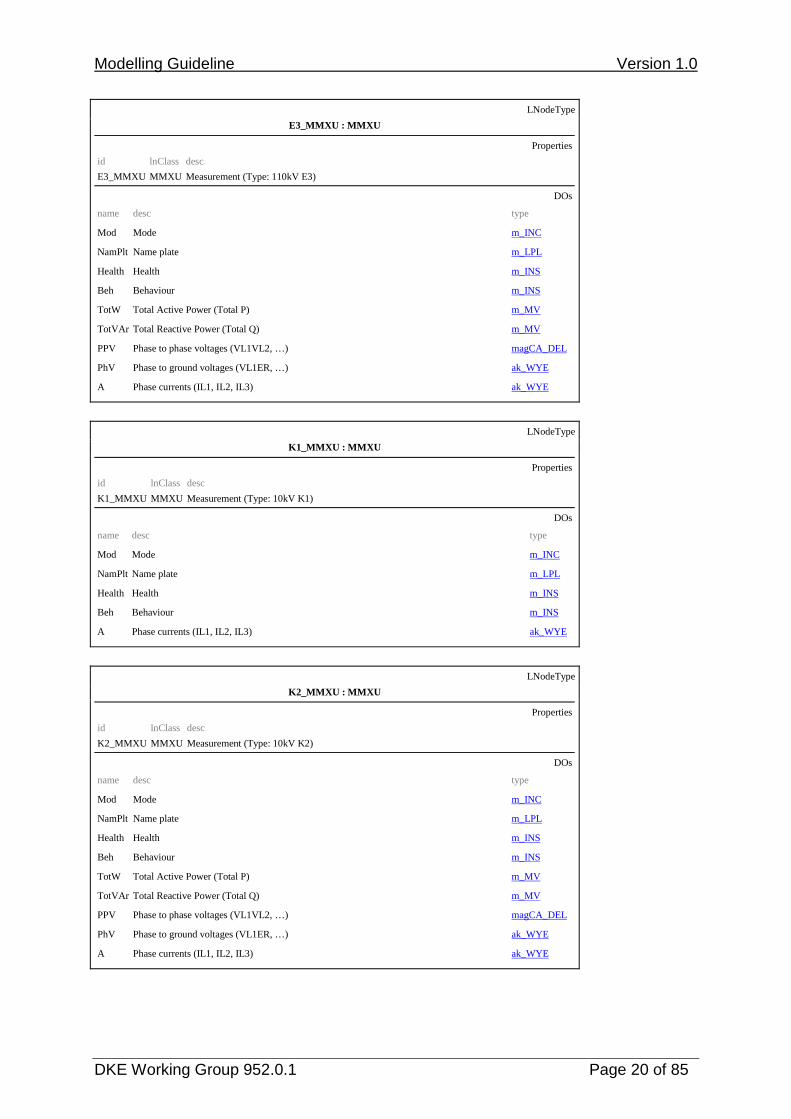
The LNs, DOs and DAs are typed and a type library is created here. The types modelled for the sample substation are presented in the following.
To limit the data volume, the enumerations are not listed in their entirety. Only the enumerations specified in IEC 61850-7-4 were included in the data attributes. The data attribute “stVal“, for instance, was not assigned to the usage-dependent enumerations but left with type INT32 which is generally valid. This is the case, for instance, with the “Controllable Integer Status INC” used in various derived data objects (e.g. Mod, OpCntRe).
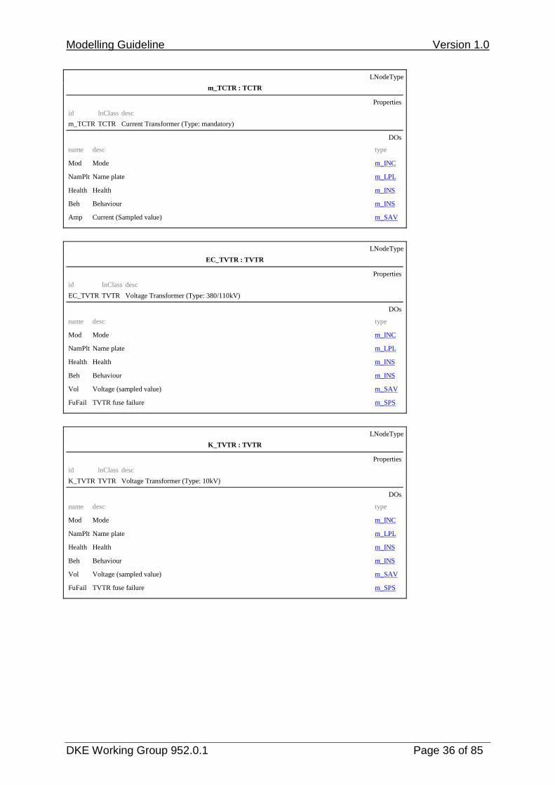
3.2.1 Logical node types LNodeType
ak_ANCR : ANCR
Properties
id lnClass desc
ak_ANCR ANCR Neutral Current Regulator (Type: AK-specific)
DOs
name desc type Mod Mode m_INC NamPlt Name plate m_LPL Health Health m_INS Beh Behaviour m_INS Loc Local operation m_SPS TapChg Change Tap Position (stop, higher, lower) ak_BSC Auto Automatic operation ak_SPC
LNodeType
ak_ATCC : ATCC
Properties
id lnClass desc
ak_ATCC ATCC Automatic Tap Changer Controller (Type: AK-specific)
DOs
name desc type Mod Mode m_INC NamPlt Name plate m_LPL Health Health m_INS Beh Behaviour m_INS Loc Local operation m_SPS ParOp Parallel/Independent operation ak_DPC CtlV Control Voltage m_MV TapChg Change Tap Position (stop, higher, lower) ak_BSC Auto Automatic/Manual operation ak_SPC

Modelling Guideline Version 1.0
DKE Working Group 952.0.1 Page 12 of 85
LNodeType
C_CALH : CALH
Properties
id lnClass desc
C_CALH CALH Alarm Handling (Type: 380kV)
DOs
name desc type Mod Mode m_INC NamPlt Name plate m_LPL Health Health m_INS Beh Behaviour m_INS GrAlm Group alarm m_SPS GrWrn1 Group warning m_SPS GrWrn2 Group warning m_SPS
LNodeType
E_CALH : CALH
Properties
id lnClass desc
E_CALH CALH Alarm Handling (Type: 110kV)
DOs
name desc type Mod Mode m_INC NamPlt Name plate m_LPL Health Health m_INS Beh Behaviour m_INS GrAlm Group alarm m_SPS GrWrn Group warning m_SPS
LNodeType
auto_CCGR : CCGR
Properties
id lnClass desc
auto_CCGR CCGR Cooling Group Control (Type: automatic)
DOs
name desc type Mod Mode m_INC NamPlt Name plate m_LPL Health Health m_INS Beh Behaviour m_INS CECtl Control of complete cooling group (pumps and fans) ak_SPC Auto Automatic or manual ak_SPC
Modelling Guideline Version 1.0
DKE Working Group 952.0.1 Page 13 of 85
LNodeType
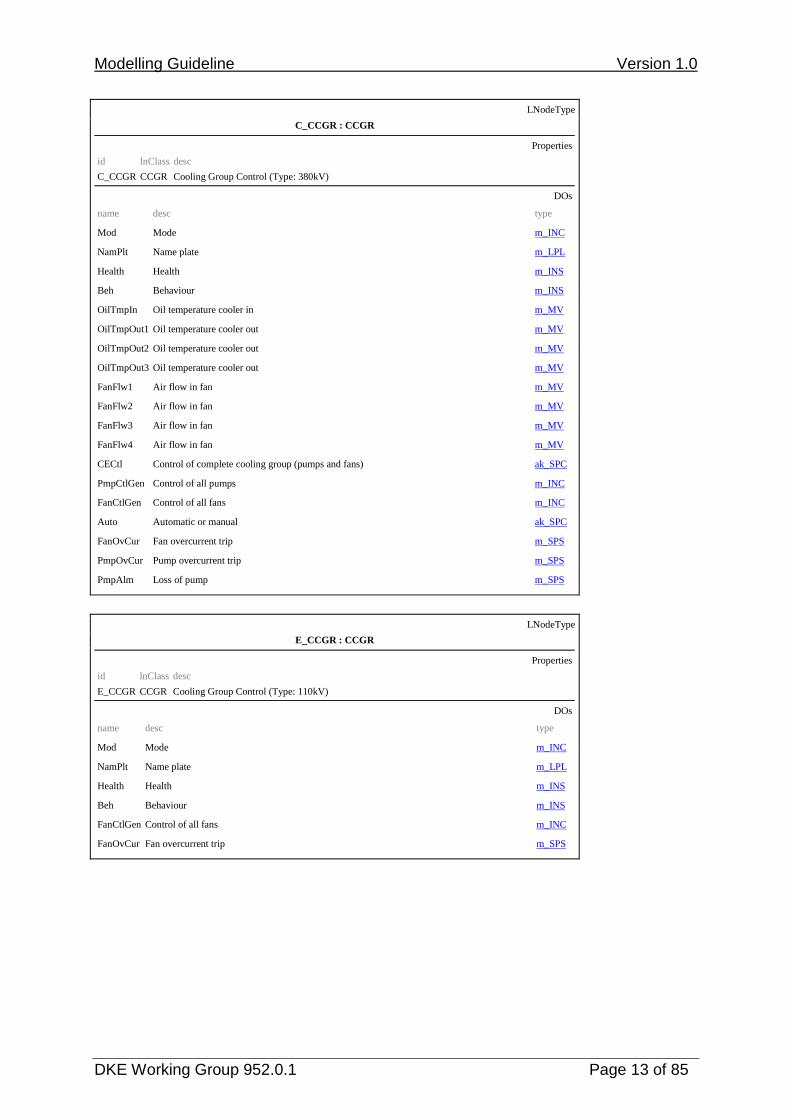
C_CCGR : CCGR
Properties
id lnClass desc
C_CCGR CCGR Cooling Group Control (Type: 380kV)
DOs
name desc type Mod Mode m_INC NamPlt Name plate m_LPL Health Health m_INS Beh Behaviour m_INS OilTmpIn Oil temperature cooler in m_MV OilTmpOut1 Oil temperature cooler out m_MV OilTmpOut2 Oil temperature cooler out m_MV OilTmpOut3 Oil temperature cooler out m_MV FanFlw1 Air flow in fan m_MV FanFlw2 Air flow in fan m_MV FanFlw3 Air flow in fan m_MV FanFlw4 Air flow in fan m_MV CECtl Control of complete cooling group (pumps and fans) ak_SPC PmpCtlGen Control of all pumps m_INC FanCtlGen Control of all fans m_INC Auto Automatic or manual ak_SPC FanOvCur Fan overcurrent trip m_SPS PmpOvCur Pump overcurrent trip m_SPS PmpAlm Loss of pump m_SPS
LNodeType
E_CCGR : CCGR
Properties
id lnClass desc
E_CCGR CCGR Cooling Group Control (Type: 110kV)
DOs
name desc type Mod Mode m_INC NamPlt Name plate m_LPL Health Health m_INS Beh Behaviour m_INS FanCtlGen Control of all fans m_INC FanOvCur Fan overcurrent trip m_SPS

Modelling Guideline Version 1.0
DKE Working Group 952.0.1 Page 14 of 85
LNodeType
m_CILO : CILO
Properties
id lnClass desc
m_CILO CILO Interlocking (Type: mandatory)
DOs
name desc type Mod Mode m_INC NamPlt Name plate m_LPL Health Health m_INS Beh Behaviour m_INS EnaOpn Enable Open m_SPS EnaCls Enable Close m_SPS
LNodeType
C_CSWI : CSWI
Properties
id lnClass desc
C_CSWI CSWI Switch Controller (Type: 380kV)
DOs
name desc type Mod Mode m_INC NamPlt Name plate m_LPL Health Health m_INS Beh Behaviour m_INS Pos Switch, general ak_DPC OpCntRs Resetable operation counter m_INC PosA Switch L1 ak_DPC PosB Switch L2 ak_DPC PosC Switch L3 ak_DPC
LNodeType
E_CSWI : CSWI
Properties
id lnClass desc
E_CSWI CSWI Switch Controller (Type: 110kV)
DOs
name desc type Mod Mode m_INC NamPlt Name plate m_LPL Health Health m_INS Beh Behaviour m_INS Pos Switch, general ak_DPC

Modelling Guideline Version 1.0
DKE Working Group 952.0.1 Page 15 of 85
LNodeType
E3_CSWI : CSWI
Properties
id lnClass desc
E3_CSWI CSWI Switch Controller (Type: 110kV E3)
DOs
name desc type Mod Mode m_INC NamPlt Name plate m_LPL Health Health m_INS Beh Behaviour m_INS Pos Switch, general ak_DPC OpCntRs Resetable operation counter ak_INC
LNodeType
K_CSWI : CSWI
Properties
id lnClass desc
K_CSWI CSWI Switch Controller (Type: 10kV)
DOs
name desc type Mod Mode m_INC NamPlt Name plate m_LPL Health Health m_INS Beh Behaviour m_INS Pos Switch, general ak_DPC OpCntRs Resetable operation counter ak_INC
LNodeType
ak_GGIO : GGIO
Properties
id lnClass desc
ak_GGIO GGIO Generic Process I/O (Type: AK-specific)
DOs
name desc type Mod Mode m_INC NamPlt Name plate m_LPL Health Health m_INS Beh Behaviour m_INS Alm General single alarm m_SPS

Modelling Guideline Version 1.0
DKE Working Group 952.0.1 Page 16 of 85
LNodeType
BC_LN0 : LLN0
Properties
id lnClass desc
BC_LN0 LLN0 Logical Node Zero (Type: BayController)
DOs
name desc type Mod Mode ak_INC NamPlt Name plate ak_LPL Health Health m_INS Beh Behaviour m_INS Loc Local operation for complete logical device m_SPS
LNodeType
m_LN0 : LLN0
Properties
id lnClass desc
m_LN0 LLN0 Logical Node Zero (Type: mandatory)
DOs
name desc type Mod Mode ak_INC NamPlt Name plate ak_LPL Health Health m_INS Beh Behaviour m_INS
LNodeType
m_LPHD : LPHD
Properties
id lnClass desc
m_LPHD LPHD Physical Device Information (Type: mandatory)
DOs
name desc type PhyName Physical device name plate ak_DPL PhyHealth Physical device health m_INS Proxy Indicates if this LN is a proxy m_SPS

Modelling Guideline Version 1.0
DKE Working Group 952.0.1 Page 17 of 85
LNodeType
C2_MDIF : MDIF
Properties
id lnClass desc
C2_MDIF MDIF Differential Measurements (Type: 380kV C2)
DOs
name desc type Mod Mode m_INC NamPlt Name plate m_LPL Health Health m_INS Beh Behaviour m_INS OpARem Operate Current (phasor) of the remote current measurement ak_WYE
LNodeType
C_MMTR : MMTR
Properties
id lnClass desc
C_MMTR MMTR Metering (Type: 380kV)
DOs
name desc type Mod Mode m_INC NamPlt Name plate m_LPL Health Health m_INS Beh Behaviour m_INS SupWh Real energy supply (default supply direction: energy flow towards busbar) m_BCR SupVArh Reactive energy supply (default supply direction: energy flow towards busbar) m_BCR DmdWh Real energy demand (default demand direction: energy flow from busbar away) m_BCR DmdVArh Reactive energy demand (default demand direction: energy flow from busbar away) m_BCR
LNodeType
C_MMXU : MMXU
Properties
id lnClass desc
C_MMXU MMXU Measurement (Type: 380kV)
DOs
name desc type Mod Mode m_INC NamPlt Name plate m_LPL Health Health m_INS Beh Behaviour m_INS TotW Total Active Power (Total P) m_MV TotVAr Total Reactive Power (Total Q) m_MV Hz Frequency range_MV PPV Phase to phase voltages (VL1VL2, …) range_DEL PhV Phase to ground voltages (VL1ER, …) range_WYE A Phase currents (IL1, IL2, IL3) ak_WYE

Modelling Guideline Version 1.0
DKE Working Group 952.0.1 Page 18 of 85
LNodeType
C1_MMXU : MMXU
Properties
id lnClass desc
C1_MMXU MMXU Measurement (Type: 380kV C1)
DOs
name desc type Mod Mode m_INC NamPlt Name plate m_LPL Health Health m_INS Beh Behaviour m_INS Hz Frequency range_MV PPV Phase to phase voltages (VL1VL2, …) ak_DEL PhV Phase to ground voltages (VL1ER, …) range_WYE
LNodeType
C6_MMXU : MMXU
Properties
id lnClass desc
C6_MMXU MMXU Measurement (Type: 380kV C6)
DOs
name desc type Mod Mode m_INC NamPlt Name plate m_LPL Health Health m_INS Beh Behaviour m_INS TotW Total Active Power (Total P) m_MV TotVAr Total Reactive Power (Total Q) m_MV PPV Phase to phase voltages (VL1VL2, …) range_DEL PhV Phase to ground voltages (VL1ER, …) range_WYE A Phase currents (IL1, IL2, IL3) ak_WYE

Modelling Guideline Version 1.0
DKE Working Group 952.0.1 Page 19 of 85
LNodeType
E1_MMXU : MMXU
Properties
id lnClass desc
E1_MMXU MMXU Measurement (Type: 110kV E1)
DOs
name desc type Mod Mode m_INC NamPlt Name plate m_LPL Health Health m_INS Beh Behaviour m_INS TotW Total Active Power (Total P) m_MV TotVAr Total Reactive Power (Total Q) m_MV Hz Frequency m_MV PPV Phase to phase voltages (VL1VL2, …) ak_DEL PhV Phase to ground voltages (VL1ER, …) ak_WYE A Phase currents (IL1, IL2, IL3) ak_WYE
LNodeType
E2_MMXU : MMXU
Properties
id lnClass desc
E2_MMXU MMXU Measurement (Type: 110kV E2)
DOs
name desc type Mod Mode m_INC NamPlt Name plate m_LPL Health Health m_INS Beh Behaviour m_INS A Phase currents (IL1, IL2, IL3) ak_WYE
Modelling Guideline Version 1.0
DKE Working Group 952.0.1 Page 20 of 85
LNodeType
E3_MMXU : MMXU
Properties
id lnClass desc
E3_MMXU MMXU Measurement (Type: 110kV E3)
DOs
name desc type Mod Mode m_INC NamPlt Name plate m_LPL Health Health m_INS Beh Behaviour m_INS TotW Total Active Power (Total P) m_MV TotVAr Total Reactive Power (Total Q) m_MV PPV Phase to phase voltages (VL1VL2, …) magCA_DEL PhV Phase to ground voltages (VL1ER, …) ak_WYE A Phase currents (IL1, IL2, IL3) ak_WYE
LNodeType
K1_MMXU : MMXU
Properties
id lnClass desc
K1_MMXU MMXU Measurement (Type: 10kV K1)
DOs
name desc type Mod Mode m_INC NamPlt Name plate m_LPL Health Health m_INS Beh Behaviour m_INS A Phase currents (IL1, IL2, IL3) ak_WYE
LNodeType
K2_MMXU : MMXU
Properties
id lnClass desc
K2_MMXU MMXU Measurement (Type: 10kV K2)
DOs
name desc type Mod Mode m_INC NamPlt Name plate m_LPL Health Health m_INS Beh Behaviour m_INS TotW Total Active Power (Total P) m_MV TotVAr Total Reactive Power (Total Q) m_MV PPV Phase to phase voltages (VL1VL2, …) magCA_DEL PhV Phase to ground voltages (VL1ER, …) ak_WYE A Phase currents (IL1, IL2, IL3) ak_WYE

Modelling Guideline Version 1.0
DKE Working Group 952.0.1 Page 21 of 85
LNodeType
K3_MMXU : MMXU
Properties
id lnClass desc
K3_MMXU MMXU Measurement (Type: 10kV K3)
DOs
name desc type Mod Mode m_INC NamPlt Name plate m_LPL Health Health m_INS Beh Behaviour m_INS Hz Frequency m_MV PPV Phase to phase voltages (VL1VL2, …) magCA_DEL PhV Phase to ground voltages (VL1ER, …) range_WYE
LNodeType
PSG_E1_MMXU : MMXU
Properties
id lnClass desc
PSG_E1_MMXU MMXU Measurement (Type: automatic synchronizer)
DOs
name desc type Mod Mode m_INC NamPlt Name plate m_LPL Health Health m_INS Beh Behaviour m_INS Hz Frequency m_MV PPV Phase to phase voltages (VL1VL2, …) ak_DEL
LNodeType
sum_MMXU : MMXU
Properties
id lnClass desc
sum_MMXU MMXU Measurement (Type: summation currents)
DOs
name desc type Mod Mode m_INC NamPlt Name plate m_LPL Health Health m_INS Beh Behaviour m_INS A Phase currents (IL1, IL2, IL3) sum_WYE
Modelling Guideline Version 1.0
DKE Working Group 952.0.1 Page 22 of 85
LNodeType
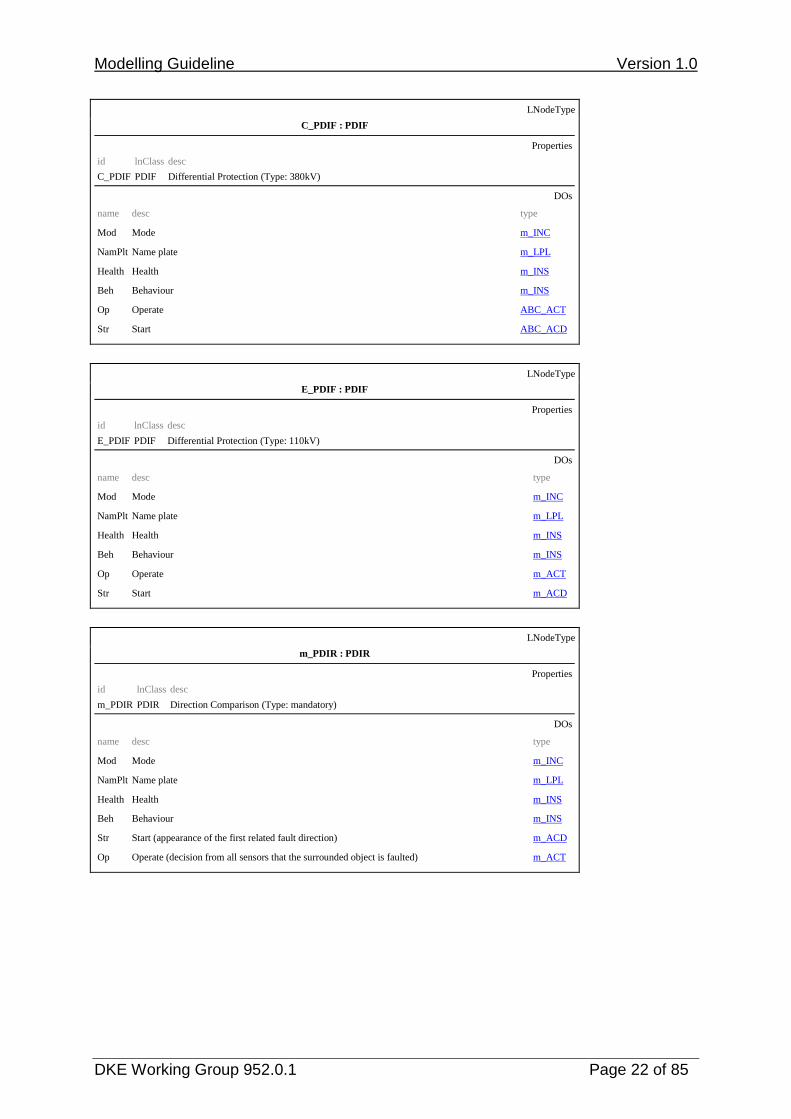
C_PDIF : PDIF
Properties
id lnClass desc
C_PDIF PDIF Differential Protection (Type: 380kV)
DOs
name desc type Mod Mode m_INC NamPlt Name plate m_LPL Health Health m_INS Beh Behaviour m_INS Op Operate ABC_ACT Str Start ABC_ACD
LNodeType
E_PDIF : PDIF
Properties
id lnClass desc
E_PDIF PDIF Differential Protection (Type: 110kV)
DOs
name desc type Mod Mode m_INC NamPlt Name plate m_LPL Health Health m_INS Beh Behaviour m_INS Op Operate m_ACT Str Start m_ACD
LNodeType
m_PDIR : PDIR
Properties
id lnClass desc
m_PDIR PDIR Direction Comparison (Type: mandatory)
DOs
name desc type Mod Mode m_INC NamPlt Name plate m_LPL Health Health m_INS Beh Behaviour m_INS Str Start (appearance of the first related fault direction) m_ACD Op Operate (decision from all sensors that the surrounded object is faulted) m_ACT
Modelling Guideline Version 1.0
DKE Working Group 952.0.1 Page 23 of 85
LNodeType
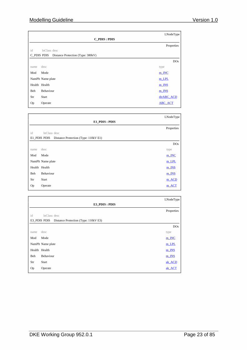
C_PDIS : PDIS
Properties
id lnClass desc
C_PDIS PDIS Distance Protection (Type: 380kV)
DOs
name desc type Mod Mode m_INC NamPlt Name plate m_LPL Health Health m_INS Beh Behaviour m_INS Str Start dirABC_ACD Op Operate ABC_ACT
LNodeType
E1_PDIS : PDIS
Properties
id lnClass desc
E1_PDIS PDIS Distance Protection (Type: 110kV E1)
DOs
name desc type Mod Mode m_INC NamPlt Name plate m_LPL Health Health m_INS Beh Behaviour m_INS Str Start m_ACD Op Operate m_ACT
LNodeType
E3_PDIS : PDIS
Properties
id lnClass desc
E3_PDIS PDIS Distance Protection (Type: 110kV E3)
DOs
name desc type Mod Mode m_INC NamPlt Name plate m_LPL Health Health m_INS Beh Behaviour m_INS Str Start ak_ACD Op Operate ak_ACT

Modelling Guideline Version 1.0
DKE Working Group 952.0.1 Page 24 of 85
LNodeType
C2_PSCH : PSCH
Properties
id lnClass desc
C2_PSCH PSCH Protection Scheme (Type: 380kV C2)
DOs
name desc type Mod Mode m_INC NamPlt Name plate m_LPL Health Health m_INS Beh Behaviour m_INS ProTx Teleprotection signal transmitted m_SPS ProRx Teleprotection signal received m_SPS Str Carrier Send m_ACD Op Operate m_ACT
LNodeType
E3_PSCH : PSCH
Properties
id lnClass desc
E3_PSCH PSCH Protection Scheme (Type: 110kV E3)
DOs
name desc type Mod Mode m_INC NamPlt Name plate m_LPL Health Health m_INS Beh Behaviour m_INS ProTx Teleprotection signal transmitted m_SPS ProRx Teleprotection signal received m_SPS Str Carrier Send m_ACD Op Operate m_ACT
LNodeType
m_PSDE : PSDE
Properties
id lnClass desc
m_PSDE PSDE Sensitive Directional Earthfault (Type: mandatory)
DOs
name desc type Mod Mode m_INC NamPlt Name plate m_LPL Health Health m_INS Beh Behaviour m_INS Str Start KdirABC_ACD

Modelling Guideline Version 1.0
DKE Working Group 952.0.1 Page 25 of 85
LNodeType
m_PTEF : PTEF
Properties
id lnClass desc
m_PTEF PTEF Transient Earth Fault (Type: mandatory)
DOs
name desc type Mod Mode m_INC NamPlt Name plate m_LPL Health Health m_INS Beh Behaviour m_INS Str Start (Transient earth fault) m_ACD
LNodeType
C_PTOC : PTOC
Properties
id lnClass desc
C_PTOC PTOC Time Overcurrent (Type: 380kV)
DOs
name desc type Mod Mode m_INC NamPlt Name plate m_LPL Health Health m_INS Beh Behaviour m_INS Str Start m_ACD Op Operate m_ACT
LNodeType
E1_PTOC : PTOC
Properties
id lnClass desc
E1_PTOC PTOC Time Overcurrent (Type: 110kV E1)
DOs
name desc type Mod Mode m_INC NamPlt Name plate m_LPL Health Health m_INS Beh Behaviour m_INS Str Start m_ACD Op Operate m_ACT

Modelling Guideline Version 1.0
DKE Working Group 952.0.1 Page 26 of 85
LNodeType
E2_PTOC : PTOC
Properties
id lnClass desc
E2_PTOC PTOC Time Overcurrent (Type: 110kV E2)
DOs
name desc type Mod Mode m_INC NamPlt Name plate m_LPL Health Health m_INS Beh Behaviour m_INS Str Start ak_ACD Op Operate m_ACT
LNodeType
K_PTOC : PTOC
Properties
id lnClass desc
K_PTOC PTOC Time Overcurrent (Type: 10kV)
DOs
name desc type Mod Mode m_INC NamPlt Name plate m_LPL Health Health m_INS Beh Behaviour m_INS Str Start KdirABC_ACD Op Operate m_ACT
LNodeType
C_PTOV : PTOV
Properties
id lnClass desc
C_PTOV PTOV Overvoltage (Type: 380kV)
DOs
name desc type Mod Mode m_INC NamPlt Name plate m_LPL Health Health m_INS Beh Behaviour m_INS Str Start m_ACD Op Operate m_ACT

Modelling Guideline Version 1.0
DKE Working Group 952.0.1 Page 27 of 85
LNodeType
C_PTRC : PTRC
Properties
id lnClass desc
C_PTRC PTRC Protection Trip Conditioning (Type: 380kV)
DOs
name desc type Mod Mode m_INC NamPlt Name plate m_LPL Health Health m_INS Beh Behaviour m_INS Tr Trip ABC_ACT Str Sum of all starts of all connected Logical Nodes dirABC_ACD
LNodeType
C2_PTRC : PTRC
Properties
id lnClass desc
C2_PTRC PTRC Protection Trip Conditioning (Type: 380kV E2)
DOs
name desc type Mod Mode m_INC NamPlt Name plate m_LPL Health Health m_INS Beh Behaviour m_INS Tr Trip ABC_ACT
LNodeType
E1_PTRC : PTRC
Properties
id lnClass desc
E1_PTRC PTRC Protection Trip Conditioning (Type: 110kV E1)
DOs
name desc type Mod Mode m_INC NamPlt Name plate m_LPL Health Health m_INS Beh Behaviour m_INS Tr Trip m_ACT Str Sum of all starts of all connected Logical Nodes ak_ACD

Modelling Guideline Version 1.0
DKE Working Group 952.0.1 Page 28 of 85
LNodeType
E2_PTRC : PTRC
Properties
id lnClass desc
E2_PTRC PTRC Protection Trip Conditioning (Type: 110kV E2)
DOs
name desc type Mod Mode m_INC NamPlt Name plate m_LPL Health Health m_INS Beh Behaviour m_INS Tr Trip m_ACT
LNodeType
E3_PTRC : PTRC
Properties
id lnClass desc
E3_PTRC PTRC Protection Trip Conditioning (Type: 110kV E3)
DOs
name desc type Mod Mode m_INC NamPlt Name plate m_LPL Health Health m_INS Beh Behaviour m_INS Tr Trip m_ACT Str Sum of all starts of all connected Logical Nodes m_ACD
LNodeType
K1_PTRC : PTRC
Properties
id lnClass desc
K1_PTRC PTRC Protection Trip Conditioning (Type: 10kV K1)
DOs
name desc type Mod Mode m_INC NamPlt Name plate m_LPL Health Health m_INS Beh Behaviour m_INS Tr Trip m_ACT

Modelling Guideline Version 1.0
DKE Working Group 952.0.1 Page 29 of 85
LNodeType
K2_PTRC : PTRC
Properties
id lnClass desc
K2_PTRC PTRC Protection Trip Conditioning (Type: 10kV K2)
DOs
name desc type Mod Mode m_INC NamPlt Name plate m_LPL Health Health m_INS Beh Behaviour m_INS Tr Trip m_ACT Str Sum of all starts of all connected Logical Nodes m_ACD
LNodeType
C_RBRF : RBRF
Properties
id lnClass desc
C_RBRF RBRF Breaker Failure (Type: 380kV)
DOs
name desc type Mod Mode m_INC NamPlt Name plate m_LPL Health Health m_INS Beh Behaviour m_INS OpEx Breaker failure trip (“external trip”) m_ACT
LNodeType
E1_RBRF : RBRF
Properties
id lnClass desc
E1_RBRF RBRF Breaker Failure (Type: 110kV E1)
DOs
name desc type Mod Mode m_INC NamPlt Name plate m_LPL Health Health m_INS Beh Behaviour m_INS OpEx Breaker failure trip (“external trip”) m_ACT

Modelling Guideline Version 1.0
DKE Working Group 952.0.1 Page 30 of 85
LNodeType
E3_RBRF : RBRF
Properties
id lnClass desc
E3_RBRF RBRF Breaker Failure (Type: 110kV E3)
DOs
name desc type Mod Mode m_INC NamPlt Name plate m_LPL Health Health m_INS Beh Behaviour m_INS OpEx Breaker failure trip (“external trip”) m_ACT OpIn Operate, retrip (“internal trip”) m_ACT
LNodeType
E3_RDIR : RDIR
Properties
id lnClass desc
E3_RDIR RDIR Directional Element (Type: 110kV E3)
DOs
name desc type Mod Mode m_INC NamPlt Name plate m_LPL Health Health m_INS Beh Behaviour m_INS Dir Direction ak_ACD
LNodeType
m_RDIR : RDIR
Properties
id lnClass desc
m_RDIR RDIR Directional Element (Type: mandatory)
DOs
name desc type Mod Mode m_INC NamPlt Name plate m_LPL Health Health m_INS Beh Behaviour m_INS Dir Direction ak_ACD

Modelling Guideline Version 1.0
DKE Working Group 952.0.1 Page 31 of 85
LNodeType
m_RDRE : RDRE
Properties
id lnClass desc
m_RDRE RDRE Disturbance Recorder Function (Type: mandatory)
DOs
name desc type Mod Mode m_INC NamPlt Name plate m_LPL Health Health m_INS Beh Behaviour m_INS RcdMade Recording made m_SPS FltNum Fault Number m_INS
LNodeType
C_RFLO : RFLO
Properties
id lnClass desc
C_RFLO RFLO Fault Locator (Type: 380kV)
DOs
name desc type Mod Mode m_INC NamPlt Name plate m_LPL Health Health m_INS Beh Behaviour m_INS FltZ Fault Impedance FltZang_CMV FltDiskm Fault Distance in km m_MV
LNodeType
E_RFLO : RFLO
Properties
id lnClass desc
E_RFLO RFLO Fault Locator (Type: 110kV)
DOs
name desc type Mod Mode m_INC NamPlt Name plate m_LPL Health Health m_INS Beh Behaviour m_INS FltZ Fault Impedance FltZang_CMV FltDiskm Fault Distance in km m_MV
Modelling Guideline Version 1.0
DKE Working Group 952.0.1 Page 32 of 85
LNodeType
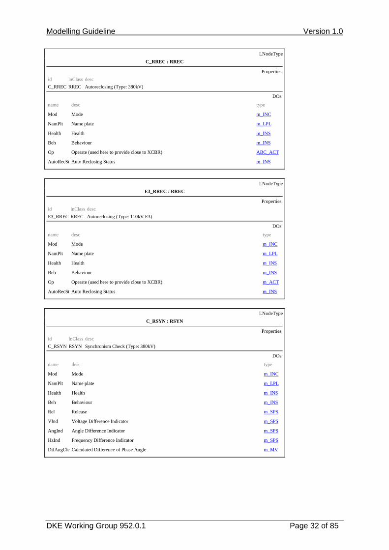
C_RREC : RREC
Properties
id lnClass desc
C_RREC RREC Autoreclosing (Type: 380kV)
DOs
name desc type Mod Mode m_INC NamPlt Name plate m_LPL Health Health m_INS Beh Behaviour m_INS Op Operate (used here to provide close to XCBR) ABC_ACT AutoRecSt Auto Reclosing Status m_INS
LNodeType
E3_RREC : RREC
Properties
id lnClass desc
E3_RREC RREC Autoreclosing (Type: 110kV E3)
DOs
name desc type Mod Mode m_INC NamPlt Name plate m_LPL Health Health m_INS Beh Behaviour m_INS Op Operate (used here to provide close to XCBR) m_ACT AutoRecSt Auto Reclosing Status m_INS
LNodeType
C_RSYN : RSYN
Properties
id lnClass desc
C_RSYN RSYN Synchronism Check (Type: 380kV)
DOs
name desc type Mod Mode m_INC NamPlt Name plate m_LPL Health Health m_INS Beh Behaviour m_INS Rel Release m_SPS VInd Voltage Difference Indicator m_SPS AngInd Angle Difference Indicator m_SPS HzInd Frequency Difference Indicator m_SPS DifAngClc Calculated Difference of Phase Angle m_MV

Modelling Guideline Version 1.0
DKE Working Group 952.0.1 Page 33 of 85
LNodeType
C4_RSYN : RSYN
Properties
id lnClass desc
C4_RSYN RSYN Synchronism Check (Type: 380kV C4)
DOs
name desc type Mod Mode m_INC NamPlt Name plate m_LPL Health Health m_INS Beh Behaviour m_INS Rel Release m_SPS VInd Voltage Difference Indicator m_SPS AngInd Angle Difference Indicator m_SPS HzInd Frequency Difference Indicator m_SPS DifHzClc Calculated Difference in Frequency m_MV DifAngClc Calculated Difference of Phase Angle m_MV
LNodeType
E_RSYN : RSYN
Properties
id lnClass desc
E_RSYN RSYN Synchronism Check (Type: 110kV)
DOs
name desc type Mod Mode m_INC NamPlt Name plate m_LPL Health Health m_INS Beh Behaviour m_INS Rel Release m_SPS DifAngClc Calculated Difference of Phase Angle m_MV
LNodeType
C_SIMG : SIMG
Properties
id lnClass desc
C_SIMG SIMG Insulation Medium Supervision Gas (Type: 380kV)
DOs
name desc type Mod Mode m_INC NamPlt Name plate m_LPL Health Health m_INS Beh Behaviour m_INS InsAlm Insulation gas critical (refill isolation medium) m_SPS InsBlk Insulation gas not safe (block device operation) m_SPS DenAlm Isolation gas density alarm m_SPS

Modelling Guideline Version 1.0
DKE Working Group 952.0.1 Page 34 of 85
LNodeType
C_SIML : SIML
Properties
id lnClass desc
C_SIML SIML Insulation Medium Supervision Liquid (Type: 380kV)
DOs
name desc type Mod Mode m_INC NamPlt Name plate m_LPL Health Health m_INS Beh Behaviour m_INS InsAlm Insulation liquid critical (refill isolation medium) m_SPS EEHealth External equipment health m_INS Tmp Insulation liquid temperature m_MV Lev Insulation liquid level m_MV Pres Insulation liquid pressure m_MV H2O Relative saturation of moisture in insulating liquid (in %) m_MV H2 Measurement of Hydrogen (H2 in ppm) m_MV TmpAlm1 Insulation liquid temperature alarm m_SPS TmpAlm2 Insulation liquid temperature alarm m_SPS GasInsAlm1 Gas in insulation liquid alarm (may be used for Buchholz alarm) m_SPS GasInsAlm2 Gas in insulation liquid alarm (may be used for Buchholz alarm) m_SPS GasInsAlm3 Gas in insulation liquid alarm (may be used for Buchholz alarm) m_SPS GasInsAlm4 Gas in insulation liquid alarm (may be used for Buchholz alarm) m_SPS GasInsTr1 Gas in insulation liquid trip (may be used for Buchholz trip) m_SPS GasInsTr2 Gas in insulation liquid trip (may be used for Buchholz trip) m_SPS GasFlwTr1 Insulation liquid flow trip because of gas (may be used for Buchholz trip) m_SPS GasFlwTr2 Insulation liquid flow trip because of gas (may be used for Buchholz trip) m_SPS GasFlwTr3 Insulation liquid flow trip because of gas (may be used for Buchholz trip) m_SPS

Modelling Guideline Version 1.0
DKE Working Group 952.0.1 Page 35 of 85
LNodeType
E_SIML : SIML
Properties
id lnClass desc
E_SIML SIML Insulation Medium Supervision Liquid (Type: 110kV)
DOs
name desc type Mod Mode m_INC NamPlt Name plate m_LPL Health Health m_INS Beh Behaviour m_INS InsAlm Insulation liquid critical (refill isolation medium) m_SPS EEHealth External equipment health m_INS TmpAlm1 Insulation liquid temperature alarm m_SPS TmpAlm2 Insulation liquid temperature alarm m_SPS GasInsAlm Gas in insulation liquid alarm (may be used for Buchholz alarm) m_SPS GasInsTr Gas in insulation liquid trip (may be used for Buchholz trip) m_SPS GasFlwTr Insulation liquid flow trip because of gas (may be used for Buchholz trip) m_SPS
LNodeType
TE1_SIML : SIML
Properties
id lnClass desc
TE1_SIML SIML Insulation Medium Supervision Liquid (Type: E-coil)
DOs
name desc type Mod Mode m_INC NamPlt Name plate m_LPL Health Health m_INS Beh Behaviour m_INS InsAlm Insulation liquid critical (refill isolation medium) m_SPS EEHealth External equipment health m_INS TmpAlm Insulation liquid temperature alarm m_SPS GasInsAlm Gas in insulation liquid alarm (may be used for Buchholz alarm) m_SPS GasFlwTr Insulation liquid flow trip because of gas (may be used for Buchholz trip) m_SPS
Modelling Guideline Version 1.0
DKE Working Group 952.0.1 Page 36 of 85
LNodeType
m_TCTR : TCTR
Properties
id lnClass desc
m_TCTR TCTR Current Transformer (Type: mandatory)
DOs
name desc type Mod Mode m_INC NamPlt Name plate m_LPL Health Health m_INS Beh Behaviour m_INS Amp Current (Sampled value) m_SAV
LNodeType
EC_TVTR : TVTR
Properties
id lnClass desc
EC_TVTR TVTR Voltage Transformer (Type: 380/110kV)
DOs
name desc type Mod Mode m_INC NamPlt Name plate m_LPL Health Health m_INS Beh Behaviour m_INS Vol Voltage (sampled value) m_SAV FuFail TVTR fuse failure m_SPS
LNodeType
K_TVTR : TVTR
Properties
id lnClass desc
K_TVTR TVTR Voltage Transformer (Type: 10kV)
DOs
name desc type Mod Mode m_INC NamPlt Name plate m_LPL Health Health m_INS Beh Behaviour m_INS Vol Voltage (sampled value) m_SAV FuFail TVTR fuse failure m_SPS

Modelling Guideline Version 1.0
DKE Working Group 952.0.1 Page 37 of 85
LNodeType
C_XCBR : XCBR
Properties
id lnClass desc
C_XCBR XCBR Circuit Breaker (Type: 380kV)
DOs
name desc type Mod Mode m_INC NamPlt Name plate m_LPL Health Health m_INS Beh Behaviour m_INS
Loc Local operation (local means without substation automation communication, hardwired direct control)
m_SPS
OpCnt Operation counter m_INS Pos Switch position ak_DPC BlkOpn Block opening ak_SPC BlkCls Block closing ak_SPC CBOpCap Circuit breaker operating capability m_INS EEHealth External equipment health m_INS SumSwARs Sum of Switched Amperes, resetable m_BCR POWCap Point On Wave switching capability m_INS
LNodeType
E_XCBR : XCBR
Properties
id lnClass desc
E_XCBR XCBR Circuit Breaker (Type: 110kV)
DOs
name desc type Mod Mode m_INC NamPlt Name plate m_LPL Health Health m_INS Beh Behaviour m_INS Loc Local operation (local means without substation automation m_SPS OpCnt Operation counter m_INS Pos Switch position ak_DPC BlkOpn Block opening ak_SPC BlkCls Block closing ak_SPC CBOpCap Circuit breaker operating capability m_INS EEHealth External equipment health m_INS

Modelling Guideline Version 1.0
DKE Working Group 952.0.1 Page 38 of 85
LNodeType
m_XCBR : XCBR
Properties
id lnClass desc
m_XCBR XCBR Circuit Breaker (Type: mandatory)
DOs
name desc type Mod Mode m_INC NamPlt Name plate m_LPL Health Health m_INS Beh Behaviour m_INS
Loc Local operation (local means without substation automation communication, hardwired direct control)
m_SPS
OpCnt Operation counter m_INS Pos Switch position ak_DPC BlkOpn Block opening ak_SPC BlkCls Block closing ak_SPC CBOpCap Circuit breaker operating capability m_INS
LNodeType
C_XSWI : XSWI
Properties
id lnClass desc
C_XSWI XSWI Circuit Switch (Type: 380kV)
DOs
name desc type Mod Mode m_INC NamPlt Name plate m_LPL Health Health m_INS Beh Behaviour m_INS Loc Local operation m_SPS OpCnt Operation counter m_INS Pos Switch position ak_DPC BlkOpn Block opening ak_SPC BlkCls Block closing ak_SPC SwTyp Switch type m_INS SwOpCap Switch operating capability m_INS EEHealth External equipment health m_INS

Modelling Guideline Version 1.0
DKE Working Group 952.0.1 Page 39 of 85
LNodeType
m_XSWI : XSWI
Properties
id lnClass desc
m_XSWI XSWI Circuit Switch (Type: mandatory)
DOs
name desc type Mod Mode m_INC NamPlt Name plate m_LPL Health Health m_INS Beh Behaviour m_INS Loc Local operation m_SPS OpCnt Operation counter m_INS Pos Switch position ak_DPC BlkOpn Block opening ak_SPC BlkCls Block closing ak_SPC SwTyp Switch type m_INS SwOpCap Switch operating capability m_INS
LNodeType
m_YEFN : YEFN
Properties
id lnClass desc
m_YEFN YEFN Petersen Coil (Type: mandatory)
DOs
name desc type Mod Mode m_INC NamPlt Name plate m_LPL Health Health m_INS Beh Behaviour m_INS Loc Local operation m_SPS ECA Earth coil current m_MV ColTapPos Coil Tap Position ak_ISC

Modelling Guideline Version 1.0
DKE Working Group 952.0.1 Page 40 of 85
LNodeType
ak_YLTC : YLTC
Properties
id lnClass desc
ak_YLTC YLTC Tap Changer (Type: AK-specific)
DOs
name desc type Mod Mode m_INC NamPlt Name plate m_LPL Health Health m_INS Beh Behaviour m_INS EndPosR End position raise reached m_SPS EndPosL End position lower reached m_SPS TapChg Change Tap Position (stop, higher, lower) ak_BSC
LNodeType
ak_YPTR : YPTR
Properties
id lnClass desc
ak_YPTR YPTR Power Transformator (Type: AK-specific)
DOs
name desc type Mod Mode m_INC NamPlt Name plate m_LPL Health Health m_INS Beh Behaviour m_INS OpOvA Operation at overcurrent m_SPS
LNodeType
ak_ZAXN : ZAXN
Properties
id lnClass desc
ak_ZAXN ZAXN Auxiliary Network (Type: AK-specific)
DOs
name desc type Mod Mode m_INC NamPlt Name plate m_LPL Health Health m_INS Beh Behaviour m_INS EEHealth External equipment health m_INS

Modelling Guideline Version 1.0
DKE Working Group 952.0.1 Page 41 of 85
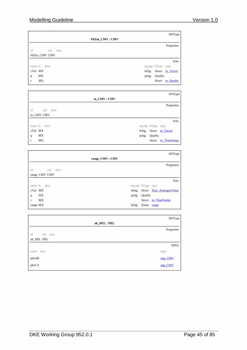
3.2.2 Data Object types DOType
ABC_ACD : ACD
Properties
id cdc desc
ABC_ACD ACD
DAs
name fc desc trg.opt. bType type
general ST dchg; BOOLEAN
dirGeneral ST dchg; Enum dir
q ST qchg; Quality
t ST Struct m_TimeStamp
phsA ST dchg; BOOLEAN
phsB ST dchg; BOOLEAN
phsC ST dchg; BOOLEAN
neut ST dchg; BOOLEAN
DOType
ak_ACD : ACD
Properties
id cdc desc
ak_ACD ACD
DAs
name fc desc trg.opt. bType type
general ST dchg; BOOLEAN
dirGeneral ST dchg; Enum dir
q ST qchg; Quality
t ST Struct m_TimeStamp
phsA ST dchg; BOOLEAN
dirPhsA ST dchg; Enum dir
phsB ST dchg; BOOLEAN
dirPhsB ST dchg; Enum dir
phsC ST dchg; BOOLEAN
dirPhsC ST dchg; Enum dir
neut ST dchg; BOOLEAN
dirNeut ST dchg; Enum dir

Modelling Guideline Version 1.0
DKE Working Group 952.0.1 Page 42 of 85
DOType
dirABC_ACD : ACD
Properties
id cdc desc
dirABC_ACD ACD
DAs
name fc desc trg.opt. bType type
general ST dchg; BOOLEAN
dirGeneral ST dchg; Enum dir
q ST qchg; Quality
t ST Struct m_TimeStamp
phsA ST dchg; BOOLEAN
dirPhsA ST dchg; Enum
phsB ST dchg; BOOLEAN
dirPhsB ST dchg; Enum
phsC ST dchg; BOOLEAN
dirPhsC ST dchg; Enum
neut ST dchg; BOOLEAN
dirNeut ST dchg; Enum
DOType
KdirABC_ACD : ACD
Properties
id cdc desc
KdirABC_ACD ACD
DAs
name fc desc trg.opt. bType type
general ST dchg; BOOLEAN
dirGeneral ST dchg; Enum dir
q ST qchg; Quality
t ST Struct m_TimeStamp
phsA ST dchg; BOOLEAN
dirPhsA ST dchg; Enum
phsB ST dchg; BOOLEAN
dirPhsB ST dchg; Enum
phsC ST dchg; BOOLEAN
dirPhsC ST dchg; Enum
DOType
m_ACD : ACD
Properties
id cdc desc
m_ACD ACD
DAs
name fc desc trg.opt. bType type
general ST dchg; BOOLEAN
dirGeneral ST dchg; Enum dir
q ST qchg; Quality
t ST Struct m_TimeStamp

Modelling Guideline Version 1.0
DKE Working Group 952.0.1 Page 43 of 85
DOType
ABC_ACT : ACT
Properties
id cdc desc
ABC_ACT ACT
DAs
name fc desc trg.opt. bType type
general ST dchg; BOOLEAN
q ST qchg; Quality
t ST Struct m_TimeStamp
phsA ST dchg; BOOLEAN
phsB ST dchg; BOOLEAN
phsC ST dchg; BOOLEAN
DOType
ak_ACT : ACT
Properties
id cdc desc
ak_ACT ACT
DAs
name fc desc trg.opt. bType type
general ST dchg; BOOLEAN
q ST qchg; Quality
t ST Struct m_TimeStamp
phsA ST dchg; BOOLEAN
phsB ST dchg; BOOLEAN
phsC ST dchg; BOOLEAN
DOType
m_ACT : ACT
Properties
id cdc desc
m_ACT ACT
DAs
name fc desc trg.opt. bType type
general ST dchg; BOOLEAN
q ST qchg; Quality
t ST Struct m_TimeStamp
DOType
m_BCR : BCR
Properties
id cdc desc
m_BCR BCR
DAs
name fc desc trg.opt. bType type
actVal ST dchg; INT128
q ST qchg; Quality
t ST Struct m_TimeStamp
pulsQty CF FLOAT32

Modelling Guideline Version 1.0
DKE Working Group 952.0.1 Page 44 of 85
DOType
ak_BSC : BSC
Properties
id cdc desc
ak_BSC BSC
DAs
name fc desc trg.opt. bType type
persistent CF BOOLEAN
ctlModel CF Enum ctlModel
ctlVal CO CODEDENUM
valWTr ST dchg; Struct ak_ValWithTrans
q ST qchg; Quality
t ST Struct m_TimeStamp
DOType
ang_CMV : CMV
Properties
id cdc desc
ang_CMV CMV
DAs
name fc desc trg.opt. bType type
cVal MX dchg; Struct ang_Vector
q MX qchg; Quality
t MX Struct m_TimeStamp
DOType
ang_range_CMV : CMV
Properties
id cdc desc
ang_range_CMV CMV
DAs
name fc desc trg.opt. bType type
cVal MX dchg; Struct ang_Vector
q MX qchg; Quality
t MX Struct m_TimeStamp
range MX dchg; Enum range
DOType
FltZang_CMV : CMV
Properties
id cdc desc
FltZang_CMV CMV
DAs
name fc desc trg.opt. bType type
cVal MX dchg; Struct ang_Vector
q MX qchg; Quality
t MX Struct m_TimeStamp
Modelling Guideline Version 1.0
DKE Working Group 952.0.1 Page 45 of 85
DOType
FltZm_CMV : CMV
Properties
id cdc desc
FltZm_CMV CMV
DAs
name fc desc trg.opt. bType type
cVal MX dchg; Struct m_Vector
q MX qchg; Quality
t MX Struct m_Quality
DOType
m_CMV : CMV
Properties
id cdc desc
m_CMV CMV
DAs
name fc desc trg.opt. bType type
cVal MX dchg; Struct m_Vector
q MX qchg; Quality
t MX Struct m_TimeStamp
DOType
range_CMV : CMV
Properties
id cdc desc
range_CMV CMV
DAs
name fc desc trg.opt. bType type
cVal MX dchg; Struct float_AnalogueValue
q MX qchg; Quality
t MX Struct m_TimeStamp
range MX dchg; Enum range
DOType
ak_DEL : DEL
Properties
id cdc desc
ak_DEL DEL
SDOs
name desc type phsAB ang_CMV phsCA ang_CMV

Modelling Guideline Version 1.0
DKE Working Group 952.0.1 Page 46 of 85
DOType
magCA_DEL : DEL
Properties
id cdc desc
magCA_DEL DEL
SDOs
name desc type phsCA m_CMV
DOType
range_DEL : DEL
Properties
id cdc desc
range_DEL DEL
SDOs
name desc type phsAB ang_range_CMV phsCA ang_range_CMV
DOType
ak_DPC : DPC
Properties
id cdc desc
ak_DPC DPC
DAs
name fc desc trg.opt. bType type
stVal ST dchg; Enum Dbpos
q ST qchg; Quality
t ST Struct m_TimeStamp
ctlModel CF Enum ctlModel
ctlVal CO BOOLEAN
origin CO Struct m_Originator
ctlNum CO INT8U
DOType
ak_DPL : DPL
Properties
id cdc desc
ak_DPL DPL
DAs
name fc desc trg.opt. bType type
vendor DC VISIBLESTRING255
hwRev DC VISIBLESTRING255
swRev DC VISIBLESTRING255
serNum DC VISIBLESTRING255

Modelling Guideline Version 1.0
DKE Working Group 952.0.1 Page 47 of 85
DOType
ak_INC : INC
Properties
id cdc desc
ak_INC INC
DAs
name fc desc trg.opt. bType type
stVal ST dchg; INT32
q ST qchg; Quality
t ST Struct m_TimeStamp
ctlModel CF Enum ctlModel
ctlVal CO INT32
DOType
m_INC : INC
Properties
id cdc desc
m_INC INC
DAs
name fc desc trg.opt. bType type
stVal ST dchg; INT32
q ST qchg; Quality
t ST Struct m_TimeStamp
ctlModel CF Enum ctlModel
DOType
m_INS : INS
Properties
id cdc desc
m_INS INS
DAs
name fc desc trg.opt. bType type
stVal ST dchg; INT32
q ST qchg; Quality
t ST Struct m_TimeStamp
DOType
ak_ISC : ISC
Properties
id cdc desc
ak_ISC ISC
DAs
name fc desc trg.opt. bType type
ctlModel CF Enum ctlModel
ctlVal CO INT8
valWTr ST dchg; Struct ak_ValWithTrans
q ST qchg; Quality
t ST Struct m_TimeStamp

Modelling Guideline Version 1.0
DKE Working Group 952.0.1 Page 48 of 85
DOType
ak_LPL : LPL
Properties
id cdc desc
ak_LPL LPL
DAs
name fc desc trg.opt. bType type
vendor DC VISIBLESTRING255
swRev DC VISIBLESTRING255
d DC VISIBLESTRING255
configRev DC VISIBLESTRING255
DOType
m_LPL : LPL
Properties
id cdc desc
m_LPL LPL
DAs
name fc desc trg.opt. bType type
vendor DC VISIBLESTRING255
swRev DC VISIBLESTRING255
d DC VISIBLESTRING255
DOType
m_MV : MV
Properties
id cdc desc
m_MV MV
DAs
name fc desc trg.opt. bType type
mag MX dchg; Struct float_AnalogueValue
q MX qchg; Quality
t MX Struct m_TimeStamp
DOType
range_MV : MV
Properties
id cdc desc
range_MV MV
DAs
name fc desc trg.opt. bType type
mag MX dchg; Struct float_AnalogueValue
q MX qchg; Quality
t MX Struct m_TimeStamp
range MX dchg; Enum range

Modelling Guideline Version 1.0
DKE Working Group 952.0.1 Page 49 of 85
DOType
m_SAV : SAV
Properties
id cdc desc
m_SAV SAV
DAs
name fc desc trg.opt. bType type
instMag MX Struct float_AnalogueValue
q MX qchg; Quality
DOType
ak_SPC : SPC
Properties
id cdc desc
ak_SPC SPC
DAs
name fc desc trg.opt. bType type
ctlModel CF Enum ctlModel
ctlVal CO BOOLEAN
stVal ST dchg; BOOLEAN
q ST qchg; Quality
t ST Struct m_TimeStamp
DOType
m_SPS : SPS
Properties
id cdc desc
m_SPS SPS
DAs
name fc desc trg.opt. bType type
stVal ST dchg; BOOLEAN
q ST qchg; Quality
t ST Struct m_TimeStamp
DOType
ak_WYE : WYE
Properties
id cdc desc
ak_WYE WYE
SDOs
name desc type phsA m_CMV phsB m_CMV phsC m_CMV

Modelling Guideline Version 1.0
DKE Working Group 952.0.1 Page 50 of 85
DOType
range_WYE : WYE
Properties
id cdc desc
range_WYE WYE
SDOs
name desc type phsA range_CMV phsB range_CMV phsC range_CMV
DOType
sum_WYE : WYE
Properties
id cdc desc
sum_WYE WYE
SDOs
name desc type res m_CMV

Modelling Guideline Version 1.0
DKE Working Group 952.0.1 Page 51 of 85
3.2.3 Data Attribute types DAType
ak_ValWithTrans
Properties
id desc
ak_ValWithTrans
DAs
name desc bType type
posVal INT8
transInd BOOLEAN
DAType
ang_Vector
Properties
id desc
ang_Vector
DAs
name desc bType type
mag Struct float_AnalogueValue
ang Struct float_AnalogueValue
DAType
float_AnalogueValue
Properties
id desc
float_AnalogueValue
DAs
name desc bType type
f FLOAT32
DAType
int_AnalogueValue
Properties
id desc
int_AnalogueValue
DAs
name desc bType type
i INT32
DAType
m_Originator
Properties
id desc
m_Originator
DAs
name desc bType type
orCat Enum orCategory
orIdent Octet64
DAType
m_TimeQuality
Properties
id desc

Modelling Guideline Version 1.0
DKE Working Group 952.0.1 Page 52 of 85
m_TimeQuality
DAs
name desc bType type
leapSecondsKnown BOOLEAN
clockFailure BOOLEAN
timeAccuracy CODED ENUM
clockNotSynchronized BOOLEAN
DAType
m_TimeStamp
Properties
id desc
m_TimeStamp
DAs
name desc bType type
secondSinceEpoch INT32
fractionOfSecond INT24U
timeQuality Struct m_TimeQuality
DAType
m_Vector
Properties
id desc
m_Vector
DAs
name desc bType type
mag Struct float_AnalogueValue
DAType
Unit
Properties
id desc
Unit
DAs
name desc bType type
SIUnit Enum SIUnit
3.2.4 Enumeration types
Only the enumerations specified in IEC 61850-7-4 were used for modelling and no further ones were defined. Therefore, they are not documented separately in the current version.

Modelling Guideline Version 1.0
DKE Working Group 952.0.1 Page 53 of 85
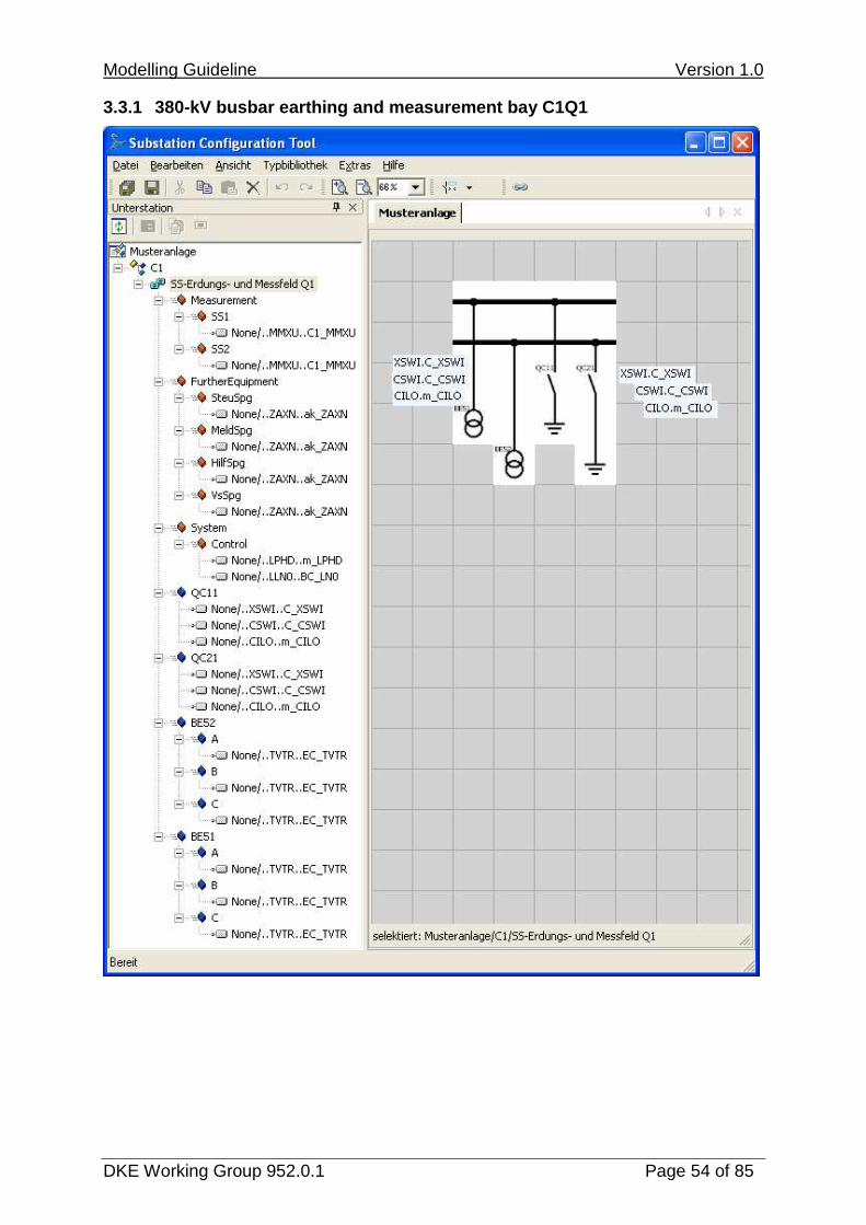
3.3 Product-independent system specification
Engineering step III:
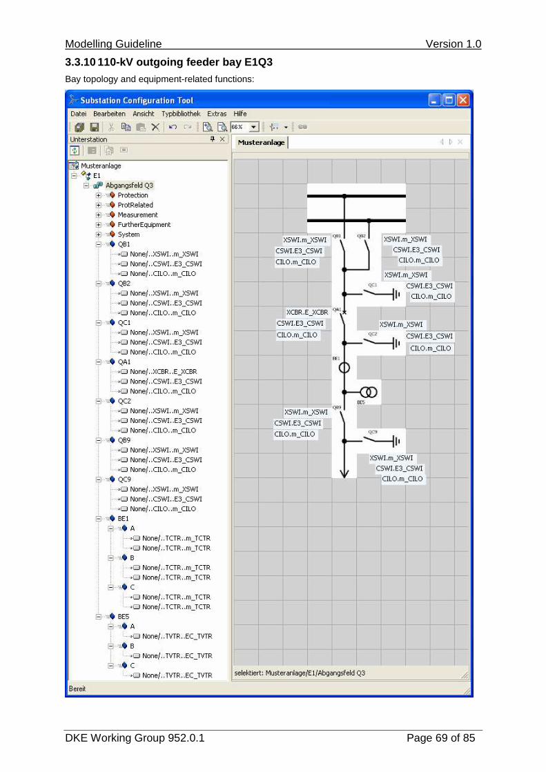
The product-independent system specification consists of the assignment of the typed information objects to the substation and the associated determination of the entire scope of information. The hierarchical information modelling is accomplished in a functional perspective (“functional naming”) using the elements “Equipment” and “Subequipment” for primary equipment and “Function” and “Subfunction” for functions. In the extension of edition 1 of IEC 61850, functions are also located under the elements “voltage level” and “bay” because otherwise an unambiguous and complete modelling is not possible.
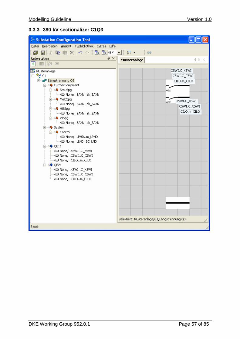
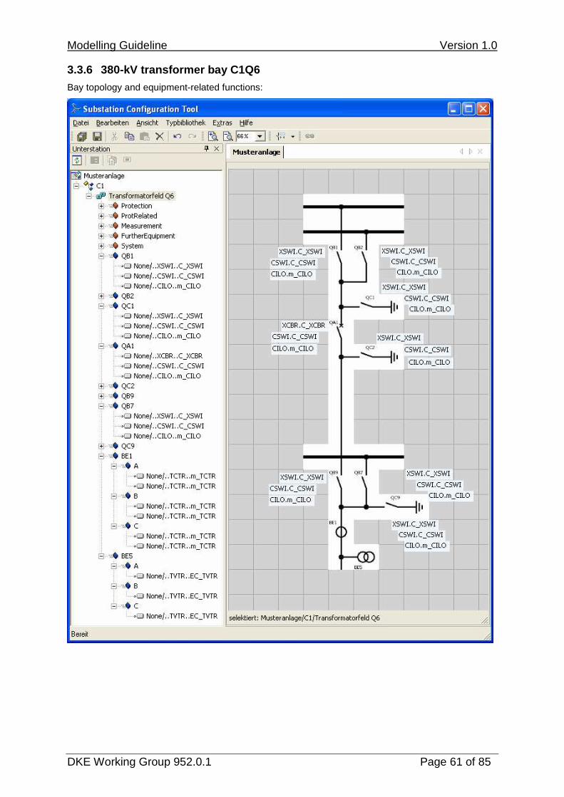
The individual bays are documented below. The bay topology and the equipment-related functions and the remaining bay functions are shown hierarchically. Elements that may be hidden in the tree views for lack of space correspond to the elements of the same type in the same picture. For instance, the LNs assigned to an isolator are usually always identical in a bay. In large bays, the topology and equipment functions are shown in the first picture and the additional bay functions in the second picture.
The identifiers of the logical nodes show the individual assignment of the LN types listed in section 0 carried out in this engineering step. The IED name “None” indicates that the product structure of the information model is still open.
Modelling Guideline Version 1.0
DKE Working Group 952.0.1 Page 54 of 85
3.3.1 380-kV busbar earthing and measurement bay C1 Q1

Modelling Guideline Version 1.0
DKE Working Group 952.0.1 Page 55 of 85
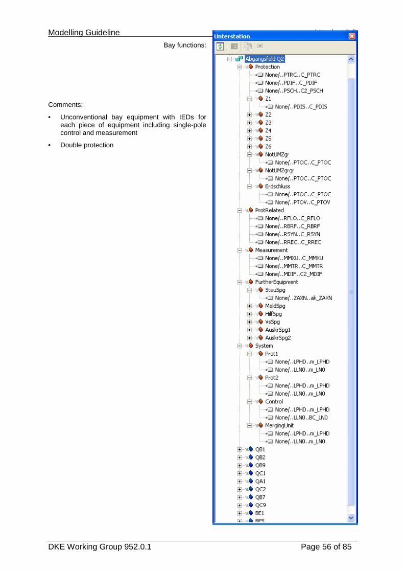
3.3.2 380-kV outgoing feeder bay C1Q2
Bay topology and equipment-related functions:
Modelling Guideline Version 1.0
DKE Working Group 952.0.1 Page 56 of 85
Bay functions:
Comments:
• Unconventional bay equipment with IEDs for each piece of equipment including single-pole control and measurement
• Double protection
Modelling Guideline Version 1.0
DKE Working Group 952.0.1 Page 57 of 85
3.3.3 380-kV sectionalizer C1Q3

Modelling Guideline Version 1.0
DKE Working Group 952.0.1 Page 58 of 85
3.3.4 380-kV coupler C1Q4
Bay topology and equipment-related functions:

Modelling Guideline Version 1.0
DKE Working Group 952.0.1 Page 59 of 85
Bay functions:
Comments:
• Three separate voltage measurements (BI5) for protection, operational measurement and automatic synchronizer

Modelling Guideline Version 1.0
DKE Working Group 952.0.1 Page 60 of 85
3.3.5 380-kV busbar earthing C1Q5
Modelling Guideline Version 1.0
DKE Working Group 952.0.1 Page 61 of 85
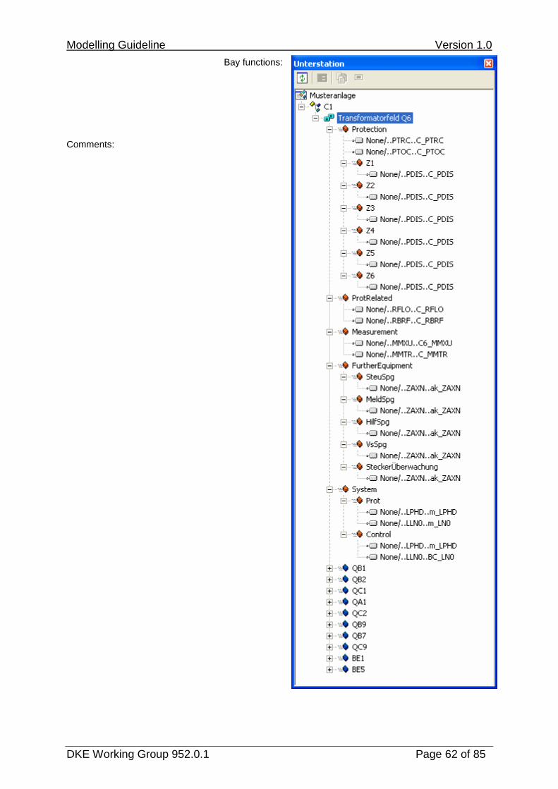
3.3.6 380-kV transformer bay C1Q6
Bay topology and equipment-related functions:
Modelling Guideline Version 1.0
DKE Working Group 952.0.1 Page 62 of 85
Bay functions:
Comments:

Modelling Guideline Version 1.0
DKE Working Group 952.0.1 Page 63 of 85
3.3.7 380/110-kV transformation T1T411
Bay topology and equipment-related functions:

Modelling Guideline Version 1.0
DKE Working Group 952.0.1 Page 64 of 85
Bay functions:
Comments:
• Independent fault recorder

Modelling Guideline Version 1.0
DKE Working Group 952.0.1 Page 65 of 85
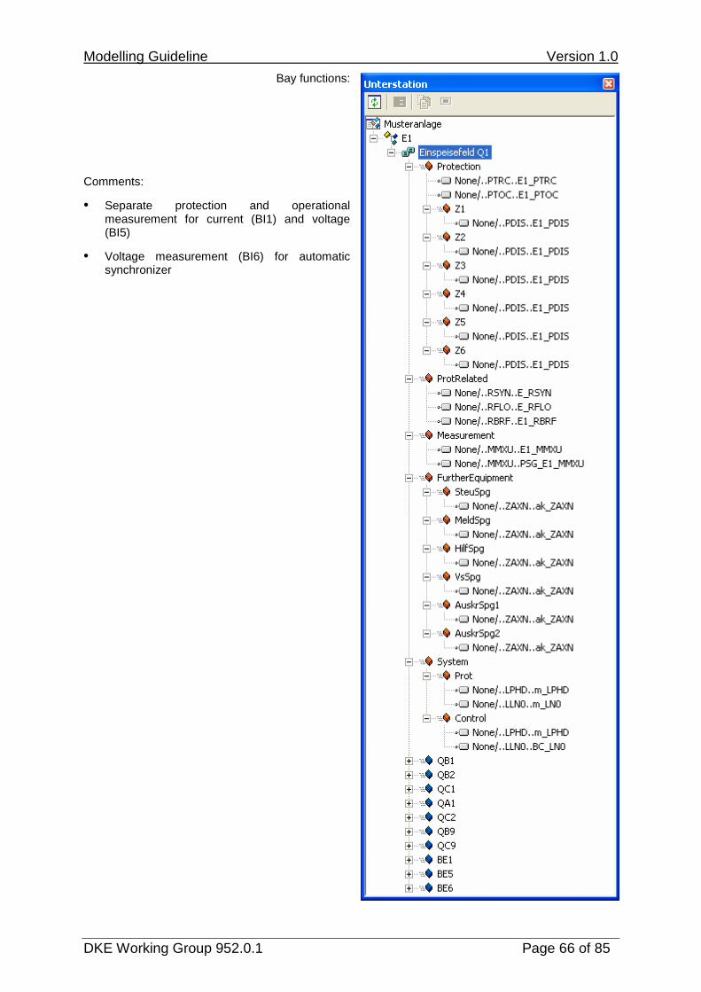
3.3.8 110-kV incoming feeder bay E1Q1
Bay topology and equipment-related functions:
Modelling Guideline Version 1.0
DKE Working Group 952.0.1 Page 66 of 85
Bay functions:
Comments:
• Separate protection and operational measurement for current (BI1) and voltage (BI5)
• Voltage measurement (BI6) for automatic synchronizer

Modelling Guideline Version 1.0
DKE Working Group 952.0.1 Page 67 of 85
3.3.9 110-kV transformer bay E1Q2
Bay topology and equipment-related functions:

Modelling Guideline Version 1.0
DKE Working Group 952.0.1 Page 68 of 85
Bay functions:
Comments:
• Operating current measurement (BI1) via protection measurement core
Modelling Guideline Version 1.0
DKE Working Group 952.0.1 Page 69 of 85
3.3.10 110-kV outgoing feeder bay E1Q3
Bay topology and equipment-related functions:

Modelling Guideline Version 1.0
DKE Working Group 952.0.1 Page 70 of 85
Bay functions:
Comments:
• Current measurement (BI1) with separate protection and operation measurement core

Modelling Guideline Version 1.0
DKE Working Group 952.0.1 Page 71 of 85
3.3.11 110/10-kV transformation T2T11 and E-coil E1 R1
Bay topology and equipment-related functions:

Modelling Guideline Version 1.0
DKE Working Group 952.0.1 Page 72 of 85
Bay functions:
Comments:
• Some functions can also be assigned to the equipment (e.g. T11 or R1) if only one LN is required (e.g. SIML, CCGR).

Modelling Guideline Version 1.0
DKE Working Group 952.0.1 Page 73 of 85
3.3.12 10-kV transformer bay K1Q1

Modelling Guideline Version 1.0
DKE Working Group 952.0.1 Page 74 of 85
3.3.13 10-kV outgoing feeder bay K1Q2

Modelling Guideline Version 1.0
DKE Working Group 952.0.1 Page 75 of 85
3.3.14 10-kV busbar earthing and measurement bay K1 Q3

Modelling Guideline Version 1.0
DKE Working Group 952.0.1 Page 76 of 85
3.4 Product mapping to actual IED structures
Engineering step IV:
In this step, the product is mapped to a concrete system structure including the associated transition to the product-related perspective. This includes the assignment to the IED names and the logical devices of the IED structure and the allocation of the instance numbers.
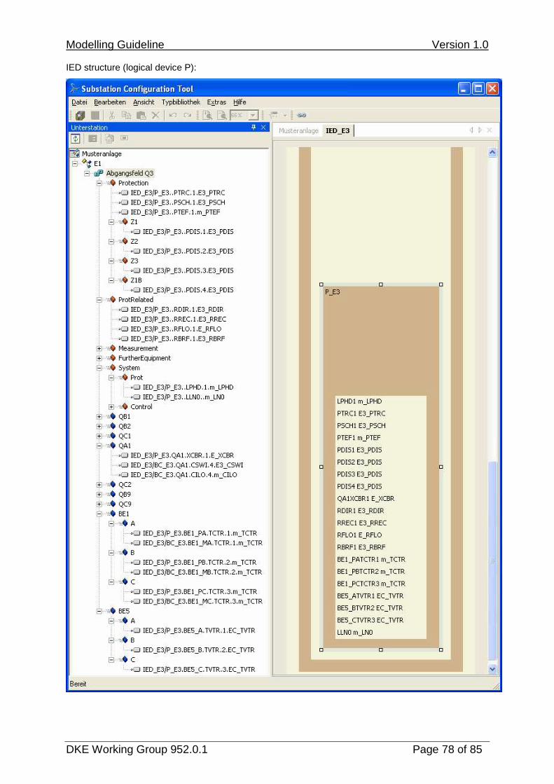
The transition to the product structure is subsequently demonstrated in two ways at the example of the 110-kV outgoing feeder bay E1Q3:
In section 0 the function-related typing is taken over into the IED. Thus, both the substation section and the IED section of the SCL data refer to the same data type.
Section 3.4.2 shows the import of a product-related typing (.icd file) which is then assigned to the function-related typing. Here, both the data type in the substation section and in the IED section is retained.

Modelling Guideline Version 1.0
DKE Working Group 952.0.1 Page 77 of 85
3.4.1 110-kV outgoing feeder bay E1Q3, taking over the function-related typing
Here, the functional perspective is taken over into the product structure. All data types from the substation section are taken over into the IED section with both sections referring to the same type. Ideally, the prefixes and instance numbers can also be assigned freely.
IED structure (logical device BC):
Modelling Guideline Version 1.0
DKE Working Group 952.0.1 Page 78 of 85
IED structure (logical device P):

Modelling Guideline Version 1.0
DKE Working Group 952.0.1 Page 79 of 85
3.4.2 110-kV outgoing feeder bay E1Q3, importing a product structure
Importing a given product structure requires a comparison with the function-related typing to be carried out.
The import is shown here at a subset of the information model only because a complete comparison would require a manual, device-specific adaptation in order to provide the required information objects (LN, DO, DA) exactly or as superset. Also no prefix was assigned to label the primary devices since it can not yet be known at the time the IED is configured. A prefix already determined by the product structure is, however, retained (e.g. for the protection zones in the illustrated example). The different types to which the substation section and IED section refer are clearly visible.

Modelling Guideline Version 1.0
DKE Working Group 952.0.1 Page 80 of 85
4 Appendix Modelling guidelines of DKE GAK 952.0.15
4.1 Introduction
Parallel to the specification of the sample substation, the GAK 952.0.15 had already defined guidelines for its modelling. The result of this modelling was textual tables regarding the information scope of the substation.
The text of the guidelines of GAK 952.0.15 (version 1.0 dated 10th February 2006) is used here to document the consistent continuation of the GAK work conducted by the working group 952.0.1. Cross-reference and comments concerning the current modelling are given to point out modifications or new findings of the SCL-based modelling. These cross-references are underlined.
The numbered items in section 4.2 refer to the bulleted list in section 2 “General Notes” and the items in section 4.2.6 refer to the bulleted list in section 3 „Rules for Modelling Data“ in part D of the GAK15 document. The irrelevant items were also listed to facilitate the orientation, but their text was not included.
4.2 General Notes
4.2.1 not relevant
4.2.2 not relevant
4.2.3 Settled or revised (see 2.1) Process modelling (switch, merging unit/transducer) only for bay C2
4.2.4 not relevant
4.2.5 The units (BC, P,...) listed in the substatio n definition (configurator) have to be modelled as logical devices each. The compila tion in physical devices is not in the focus of the working group.
4.2.6 not relevant

Modelling Guideline Version 1.0
DKE Working Group 952.0.1 Page 81 of 85
4.3 Rules for modelling data
4.3.1 Revised: “-“ is not permitted as part of the name. Replaced by underscore. Naming for logical devices (LD): The name is compos ed of the designation of the LD in the configurator and the s ubstation partial name. Examples: P-E1, P1-C2, BC-K2, etc.
4.3.2 Settled, see 0.. If a LN is required for modelling, an instance has to be created. A prefix is used for process LNs which integrates the design ation of the process device, e.g. LN XCBR – name of process device Q0 – instance Q0XCBR.
4.3.3 Irrelevant since modelled with SCL. Revised according to 2.1. All LNs that only exists in a functional perspectiv e and are thus not transferred to a communication bus outside of a dev ice are written in italics and only indicated in the tables of the LDs . A further detailed description in the subordinate LN tables is not pro vided, e.g. data which is transmitted between LNs in one device only.
4.3.4 Irrelevant since modelled with SCL. Column Value & Report Text: Message texts in the co lumn “Values and Report Text” are written without equals sign and in upper case. Example: OK / WARNUNG/ STOER. Values of attributes are highl ighted by a preceding equals sign and are always written in low er case. Example: „= false“ or „= status-only“.
4.3.5 Settled, see 2.1: All process connections are modelled. All switching functions (XCBR, XSWI) in the 380-kV level for which the process bus is used/modelled must have the poles mo delled individually (Q0XCBR1 ...3, XSWI1 …3). This concerns only substa tion part C2. 380-kV switching devices wired in parallel are modelled in the bay device by an XCBR/XSWI instance.
4.3.6 Settled, is modelled with “subequipment”. For all switch controls (CSWI) in the 380-kV level the positions of the individual poles must be indicated. CSWI: Pos, PosA , PosB, PosC
4.3.7 Modelling the datum position of CSWI and XCBR : Generally, switching is always with “Enhanced Security”. In case of a bay-oriented process bus, the “direct- with-enhanced-security” control model is sufficient for the XCBR. Reason: There is only one control point that can access the XCBR, therefo re an SBO (Select Before Operate) is not necessary. When communicating via the substation bus (substati on controller - bay controller), the “sbo-with-enhanced-security” contr ol model is required for CSWI. Reason: Risk that several control points want to access CSWI simultaneously. If the circuit breaker XCBR is wired in parallel, t he “direct-with-enhanced-security” control model is required for th e XCBR.
Modelling Guideline Version 1.0
DKE Working Group 952.0.1 Page 82 of 85
4.3.8 Settled since entirely modelled with SCL. Representation of nested data (e.g. for CDC WYE and DEL) Only the first datum is entered in the “Data” colum n. All other (nested) data are shown together with the attribute in the c olumn “(Data.)Attribute“. Example PPV.phsCA.cVal.mag representation under column “Data”: PPV representation under column „(Data.)Attribute“: phs CA.cVal.mag
4.3.9 Settled, see 0. Data Mode: The attribute “ctlval” shall only be use d in LLNO; the attribute “ctlval” shall not be used for all other logical nodes but only the attribute “stVal”. The following attributes shall be used: ctlVAL (LLNO only), stVal, q, t, ctlModel Reason: Limiting the data volume, e.g. it does not make sense to switch off the fifth zone of the distance protection, secu rity aspect “overriding certain functions should only be possible locally” Information: The information block is set via a par ameter of the report.
4.3.10 The following attributes shall be used for c ontrolling a switching device (e.g. Data Pos, CDC DPC): ctlVal, stVal, origin, ctlNum, q, t, ctlModel
4.3.11 OpCntRs should only be controllable locally, i.e. no ctlVal. Reason: corresponds to present-day practice.
4.3.12 The following attributes shall be used for t he datum NamPlt: vendor, swRev, d The configRev attribute may only be used in LLN0.
4.3.13 The data TotW and TotVAr must be modelled ac cording to the information list in bay C2 in MMXU.
4.3.14 Settled, see 2.1.3. The LN GGIO (or GAPC) can be used for messages or the like for which no LNs or DATA are available. An y number of instances can be created for the DATA within this L N. A serial number is suffixed to form an instance. Example: BinIn ���� BinIn1, BinIn2
4.3.15 Not used. New LNs or DATA shall be created according to the r ules of IEC 61850-7-4 Annex A for data that can not be modelled by exis ting LNs or DATA. These newly defined objects shall be commented corr espondingly, i.e. why and for which purpose the new object was create d. When naming the objects use the proposed abbreviations (see IEC 61850-7-4 chap. 4). If these abbreviations are not sufficent, a new abb reviation can be created. This new abbreviation must be commented, t oo.
4.3.16 Use LN LPHD for physical device messages.
4.3.17 Settled or revised, see 0. LNs of the type ZAXN (auxiliary network) are used t o monitor the auxiliary voltages. One LN ZAXN is used for each ba y with the DATA of

Modelling Guideline Version 1.0
DKE Working Group 952.0.1 Page 83 of 85
all monitored voltages. The following DATA are supp lemented in ZAXN for this purpose: EEHealth1 ... EEHealth2 etc.
4.3.18 System monitoring via DATA “Health”: FE STOE R (bay unit fault) and FE WARNG (bay unit warning) are defined in LPHD of the corresponding LD (each via Health). The messages report physical dis turbance; functional (logical) disturbances are documented by the Healt elements of the corresponding LNs. The user functions of the device in use must ensure that all LPHD nodes within the device have the same Health status.
4.3.19 Settled or revised, see 0, 2.1.3. Monitoring of the control voltage enters both ZAXN and equipment EEHealth. Monitoring of control voltage of switching device: Is it desired that the supervision of the control voltage of a switching d evice is fed into the “Health” function of the associated LN QxCSWI? Heal th = green means that the device can be switched. Decision: Health o nly for function-related conditions, do not use to incorporate exter nal information to this function. Monitoring of the control voltage of a sw itching device must be implemented via ZAXN.
4.3.20 Synchro check/ parallel switching: The refer ence system for the voltages to be synchronized must be identical. It is not cle ar whether this can be used as a base for the measured value acquisition i n the two devices involved when the time is set via the bus (high acc uracy requirement: simultaneous detection in both locations). Pragmati c solution: Wiring the required measured values to the RSYN devices. A lternative solution: Clocking of the transformers e.g. via external cloc k-pulse generation (clock input in the merging unit or at the intellig ent transformer).
4.3.21 RSYN (synchro check/ parallel switching): Th e angle difference must be modelled. The difference of voltage and frequency i s not necessary because the two values have to be provided from the bay value and comparison value and have to be displayed according to the information list.
4.3.22 The busbar protection based on the pickup co mparison is modelled via PDIR (reverse interlocking).
4.3.23 Settled, see 0. Setpoints (ASP): Remove all setpoints/settings from the modelling, since they are often manufacturer-specific.
4.3.24 NOT-UMZ (backup O/C protection) (for distanc e protection and voltage failure) is modelled as blocked or On in the DATA m ode of LN PTOC.
4.3.25 Using the attributes available in the standa rd for monitoring to the extent available.
4.3.26 Settled, see Application Description Information blocks (e.g. data transmission stop) ar e implemented by setting the ReportControls which are defined separa tely to ‘disabled’ via the service SetDataValue. Please note in this conte xt that the possibility
Modelling Guideline Version 1.0
DKE Working Group 952.0.1 Page 84 of 85
to define ReportControls may be limited by the avai lable device technology.
4.3.27 Settled, see Application Description Local control to be modelled, using the datum Loc o nly in LN LLNO.
4.3.28 Settled, see Application Description Only the corresponding (of each level) local/remote switchover is taken into account, i.e. one message “local” or “remote” is issued for each switchover. But how is a command block implemented from the HMI (i.e. remote/local switchover from HMI for one bay)? No m odelling required or the datum Loc must be present in the bay.
4.3.29 NAHSTEU = control on substation level ORTSTEU = control on bay level FERNSTEU = control on network control level Only the corresponding (of each level) local/remote switchover is taken into account, i.e. one message “local” or “remote” is issued for each switchover.
4.3.30 How is a command block implemented from the HMI (i.e. remote/local switchover from HMI for one bay)? No modelling requ ired or the datum Loc must be present in the bay.
4.3.31 Remote deactivation of an interlock is not m odelled.
4.3.32 “Name Space” only has to be used if LN, data , attribute or CDC are changed or added. “Name Space” must therefore not b e used if these data are used unchanged.
4.3.33 Values have to be specified for some attribu tes, e.g. for ctlModle, etc.
4.3.34 A fault recording must be modelled as a sepa rate logical device.
4.3.35 Settled, see 0. If the auxiliary voltage is affected, the monitorin g by ZAXN comes additionally. For trip circuit supervision, the datum EEHealth of the corresponding LNs (XCBR, XSWI) must be used. Message “trip circui t failure”.
4.3.36 The messages measured value supervision of c urrent and voltage and phase sequence supervision are not modelled initial ly because no corresponding objects are available in IEC 61850.Po ssible solution: Create a new LN “SMMX” (supervision measurands for plausibility check of the sampled values, e.g. warning too few samples ).
4.3.37 The message WDL SPG FEHL (no transformer vol tage available) is modelled as FUFAIL in TVTR.
4.3.38 The message FE KOMM STOER (bay unit fault co ming) is not considered any further for the modelling purpose since no comm unication via the bus is derived from it. -> In this context, see con nection management in IEC 61850-7-2.

Modelling Guideline Version 1.0
DKE Working Group 952.0.1 Page 85 of 85
4.3.39 MIT PSG NICHT MÖGLICH (not possible with aut omatic synchronizer): This message is generated if the comparison bay is without voltage and the bay to be connected belongs to a certain bay ty pe (e.g. machine bay, certain coupling bays). The bypassing logic used fo r normal bays (if the reference bay is dead, connection is permitted with out automatic synchronizer check) is not permitted for these bay types. Switching of the automatic synchronizer is therefore aborted in this case. This message is irrelevant for the GAK model substation and can be omitted.
4.3.40 PSG NICHT VORH (automatic synchronizer not a vailable): This message is generated by the substation control unit if the command “with automatic synchronizer” is sent via remote control but no automatic synchronizer is present in the bay in question.
4.3.41 The messages/commands for switching the meas ured value cycles contained in the lists (e.g. in E1: “KURZ ZYKL EIN” ) are not modelled since the demands on the transmission of measured v alues basically refer to the transmission path between substation a nd network control center. The demands must be defined there.
4.3.42 Settled, see Application Description FE-Test (bay unit test): This message is largely op erator-specific and can be omitted.
4.4 Further modifications to the GAK15 modelling
4.4.1 An earth fault detection for the 380-kV subst ation section is not planned because of the earthed starpoint.
5 Literature [1] Harnischmacher, G.; Arph, J.; Hölscher, M.: Effiziente Datenmodellierung im
Anlagenengineering nach IEC 61850. etz Elektrotechnik + Automation, 128. Jahrg., Heft 4/2007, S. 40-51(ISSN 0948-7387).