modelling of friction for high temperature extrusion of
TRANSCRIPT

1
Modelling of friction for high temperature extrusion
of aluminium alloys
Liliang Wang

2

3
Modelling of friction for high temperature
extrusion
of aluminium alloys
Proefschrift
ter verkrijging van de graad van doctor
aan de Technische Universiteit Delft,
op gezag van de Rector Magnificus prof. ir. K.C.A.M. Luyben,
voorzitter van het College voor Promoties,
in het openbaar te verdedigen op maandag 6 februari 2012 om 12.30 uur
door
Liliang WANG
Master of Engineering
Harbin Institute of Technology, China
geboren te Liaoning, China

4
Dit proefschrift is goedgekeurd door de promotor:
Prof. ir. L.Katgerman
Copromotor Dr. J. Zhou
Samenstelling promotiecommissie:
Rector Magnificus, voorzitter
Prof. ir. L. Katgerman, Technische Universiteit Delft, promotor
Dr. J.Zhou, Technische Universiteit Delft, copromotor
Prof.dr. ir. D.J.Schipper, Universiteit Twente
Prof.dr.ir.J. Sietsma, Technische Universiteit Delft
Prof.dr. R. Boom, Technische Universiteit Delft
Prof. Dr. I.M. Richardson, Technische Universiteit Delft
Prof.ir. F. Soetens, Technische Universiteit Eindhoven
Modelling of friction for high temperature extrusion of aluminium alloys
PhD thesis Delft University of Technology, with summary in Dutch
Keywords: Extrusion, friction, aluminium alloys
ISBN: 978-94-6182-078-5
Copyright ©2012 by Liliang Wang
All rights reserved. No part of the materials protected by this copy right notice may be
reproduced or utilized in any form or by any means, electronical or mechanical, including
photocopying, recording or by any information storage and retrieval system, without written
permission from the author.

5
Table of Contents
Modelling of friction for high temperature extrusion of aluminium alloys ............................... 1
Chapter 1 INTRODUCTION ................................................................................................. 1
1.1 Background ........................................................................................................... 1
1.2 Determination of friction coefficients ................................................................... 2
1.3 Thesis Layout ........................................................................................................ 3
References .................................................................................................................................. 5
Chapter 2 LITERATURE REVIEW ...................................................................................... 8
2.1 The origins of friction ........................................................................................... 8
2.1.1 The classic friction laws ........................................................................................ 8
2.1.2 The origins of friction – a brief review of the theories of friction ........................ 9
2.2 Friction characterization techniques for extrusion processes .............................. 14
2.2.1 Ring compression test ......................................................................................... 14
2.2.2 Extrusion friction test for billet/container interface ............................................ 22
2.2.3 Localized friction measurement techniques ........................................................ 27
2.2.4 Comparisons of friction testing techniques for extrusion processes ................... 32
2.3 Friction models for extrusion processes .............................................................. 38
2.3.1 Coulomb friction model ...................................................................................... 38
2.3.2 Shear friction model ............................................................................................ 38
2.3.3 Temperature based friction model for the billet/container interface ................... 39
2.3.4 Empirical friction models for the bearing channel of extrusion dies .................. 39
2.3.5 Physical friction model for the bearing channel of extrusion dies ...................... 41

6
2.3.6 Comparison of different friction models ............................................................. 42
References ................................................................................................................................ 43
Chapter 3 MODELLING OF HIGH TEMPERATURE BALL-ON-DISC TESTS ............ 50
ABSTRACT ......................................................................................................................... 50
3.1 Introduction ......................................................................................................... 51
3.2 Model development ............................................................................................. 52
3.2.1 Existing models for scratch tests ......................................................................... 52
3.2.2 Extension of the models to ball-on-disc tests ...................................................... 53
3.3 Experimental details ............................................................................................ 58
3.4 Experimental results ............................................................................................ 59
3.5 Determination of the integral parameters in the model ....................................... 60
3.6 Application of the model ..................................................................................... 61
3.6.1 Ploughing and shear friction coefficients ............................................................ 62
3.6.2 Mean contact pressure ......................................................................................... 63
3.6.3 Comparison between Equation 3.5 and Equation 3.6 ......................................... 63
3.7 Conclusions ......................................................................................................... 64
References ................................................................................................................................ 65
Chapter 4 DETERMINATION OF FRICTION COEFFICIENT FOR THE BEARING
CHANNEL OF THE HOT ALUMINIUM EXTRUSION DIE ............................................... 67
ABSTRACT ......................................................................................................................... 67
4.1 Introduction ......................................................................................................... 68
4.2 Materials and experimental procedure ................................................................ 68
4.3 Results and discussion ......................................................................................... 69
4.3.1 Evolution of friction coefficient with sliding distance ........................................ 69

7
4.3.2 Evolution of shear friction stress ......................................................................... 74
4.3.3 Influence of temperature on the shear friction stress .......................................... 74
4.4 Physically-based adhesive strength friction model (ASFM) for the bearing
channel of hot aluminium extrusion die ............................................................................... 76
4.5 Conclusions ......................................................................................................... 78
References ................................................................................................................................ 78
Chapter 5 DOUBLE ACTION EXTRUSION - A NOVEL EXTRUSION PROCESS FOR
FRICTION CHARACTERIZATION AT THE BILLET DIE BEARING INTERFACE ....... 81
ABSTRACT ......................................................................................................................... 81
5.1 Introduction ......................................................................................................... 82
5.2 Experimental and simulation details ................................................................... 82
5.3 Theoretical modelLing of double action extrusion ............................................. 86
5.3.1 Theoretical background ....................................................................................... 86
5.3.2 Integral constants determination ......................................................................... 89
5.3.3 Material model for AA7475 ................................................................................ 90
5.3.4 Strain rate determination ..................................................................................... 91
5.3.5 Governing equations ........................................................................................... 92
5.4 Results and model verification ............................................................................ 92
5.4.1 Typical DAE results ............................................................................................ 92
5.4.2 Steady-state extrusion force ................................................................................ 94
5.4.3 Extrudate lengths and validation of theoretical model ........................................ 95
5.5 Conclusions ....................................................................................................... 101
References .............................................................................................................................. 101
Chapter 6 CONCLUSIONS, DISCUSSIONS AND RECOMMENDATIONS ................ 104

8
6.1 CONCLUSIONS ............................................................................................... 104
6.2 Discussions ........................................................................................................ 106
6.2.1 Friction characterization for the bearing channel of hot aluminium extrusion die
by using ball on disc tests ............................................................................................... 106
6.2.2 Nature of friction in the bearing channel of hot aluminium extrusion dies ...... 109
6.3 recommendations .............................................................................................. 110
6.3.1 Short sliding distance ball-on-disc tests ............................................................ 110
6.3.2 Double action extrusion tests ............................................................................ 111
References .............................................................................................................................. 111
SUMMARY ........................................................................................................................... 114
SAMENVATTING ................................................................................................................ 115
LIST OF PUBLICATION ...................................................................................................... 116
ACKNOWLEDGEMENTS ................................................................................................... 117
Appendix A Flow stress of AA7475 at different temperatures ................. 119
Appendix B Constitutive parameters for aluminium alloys ...................... 122
References .............................................................................................................................. 123

1
Chapter 1
INTRODUCTION
1.1 BACKGROUND
Extrusion is a process in which a cast billet of solid metal is converted into a continuous
length of generally uniform cross-section by forcing it to flow through a shaped die opening.
Generally, the extrusion process is a hot working operation, in which the metal billet is heated
to a proper temperature, at which a relatively high ductility and low flow stress can be
achieved. Figure 1.1 shows the principle of direct extrusion. The extrusion die is located at
one end of the container, and the billet to be extruded is pushed towards the die.
Figure 1.1 Schematic working principle of direct extrusion process.
Hot extrusion is widely used for the manufacturing of near-net-shape solid and hollow
sections [1-5]. In recent years, the increasing demands of such profiles in automobile and
aircraft industries have led to a demand for a better understanding of the process. On the other
hand, hot aluminium extrusion involves complex thermo-mechanical and chemical
interactions between hot aluminium and tool-steel tooling [5-7] (mainly extrusion die and
Stem
Container
Billet Extrudate
Extrusion die

2
container) and the local contact conditions at the work piece/tooling interfaces are of great
influence on process parameters, such as productivity, product quality and scrap rate. In
recent years, finite-element (FE) simulations have been extensively used in scientific research
and industrial practice to analyse the process and to aid in process optimization. A basic issue
of FEM simulations is the accuracy of the results, which is mainly determined by the
viscoplastic material behavior of aluminium alloys at elevated temperatures (temperature and
strain rate sensitive); and the assignment of boundary conditions, especially the friction
boundary condition [8-20]. However there remain some uncertainties in the selection of
friction models and the determination of friction coefficients, because the friction
phenomenon, especially the friction at elevated temperatures, is not fully understood yet.
1.2 DETERMINATION OF FRICTION COEFFICIENTS
In the past years, some efforts have been made to study the tribological phenomenon of the
extrusion process and the experiments conducted can be classified as three different types,
namely, field tests, e.g. extrusion friction tests [12, 13, 15, 16, 18, 21, 22]; physical simulation
tests, e.g. block on disc tests [6, 23, 24]; and tribological tests, e.g. ball-on-disc tests [25-29].
The three types of tribological tests were not compared yet and this is the subject within this
research. Figure 1.2 summarizes the friction characterization techniques for the extrusion
processes.
Figure 1.2 Summary of the friction characterization techniques for extrusion processes.
Friction at billet/container interface:
Extrusion test + FE simulation
Forward extrusion with different billet lengths + Theory
Billet with rod markers embedded
Friction in the bearing channel of extrusion dies:
Extrusion tests: sticking and slipping
lengths on the bearing surface
Block on disc test
Ball/Pin on disc test

3
1.3 THESIS LAYOUT
This thesis deals with the assignment of friction boundary conditions for hot aluminium
extrusion process. Issues addressed are the high-temperature ball-on-disc tests, friction
modelling, double action extrusions and computer simulations of the hot aluminium extrusion
process. The layout of the thesis is illustrated in Figure 1.3.
In Chapter 1, the background of the present research is introduced
In Chapter 2, the basic theories of friction are introduced and the techniques for the friction
characterization of extrusion processes are reviewed. In addition, the commonly used friction
models for extrusion processes are reviewed.
In Chapter 3, a model for high-temperature ball-on-disc test is developed. The individual
contributions of shearing and ploughing friction are studied, and the evolution of wear track
or mean contact pressure during the ball-on-disc tests is characterized.
In Chapter 4, the friction stress between hot aluminium and H11 tool steel is determined by
using short sliding distance ball-on-disc tests. Based on the testing results, a physically based
friction model for the bearing channel of hot aluminium extrusion die is developed.
In Chapter 5, a novel extrusion process, double action extrusion (DAE), is developed to
highlight the friction in the bearing channel of aluminium extrusion dies. Both theoretical and
FE modelling of this novel process are conducted and the working mechanism of the DAE is
analysed. In addition, the adhesive strength friction model (developed in Chapter 3) is
implemented into the FE simulation of hot aluminium extrusion process and this model is
experimentally verified.
In Chapter 6, the most important conclusions of this thesis are summarized. The friction
testing techniques for extrusion processes and the nature of friction in the bearing channel of
hot aluminium extrusion process are discussed. Finally, recommendations for further research
are proposed.

4
Figure 1.3 Layout of the thesis.
Ball-on-disc tests
and modelling
Friction modelling for
hot aluminium extrusion
To highlight the friction in the
bearing channel of extrusion die
Chapter 6: Conclusions, discussions
and future
recommendations
Summary
Chapter 3: Modelling of high
temperature ball-on-
disc tests
Chapter 4: Determination of friction
coefficient for the bearing
channel of the hot
aluminium extrusion die
Chapter 5: Double action extrusion - a
novel extrusion process for
the friction characterization at
the billet-die bearing interface
and friction model verification
Chapter 1: Introduction
Chapter 2: Literature review

5
References
[1] G. Liu, J. Zhou, and J. Duszczyk, "FE analysis of metal flow and weld seam formation
in a porthole die during the extrusion of a magnesium alloy into a square tube and the
effect of ram speed on weld strength," Journal of materials processing technology, vol.
200, pp. 185-198, May 2008.
[2] G. Fang, J. Zhou, and J. Duszczyk, "Effect of pocket design on metal flow through
single-bearing extrusion dies to produce a thin-walled aluminium profile," Journal of
materials processing technology, vol. 199, pp. 91-101, Apr 2008.
[3] L. Li, J. Zhou, and J. Duszczyk, "Prediction of temperature evolution during the
extrusion of 7075 aluminium alloy at various ram speeds by means of 3D FEM
simulation," Journal of materials processing technology, vol. 145, pp. 360-370, 2004.
[4] X. Duan, X. Velay, and T. Sheppard, "Application of finite element method in the hot
extrusion of aluminium alloys," Materials Science and Engineering A, vol. 369, pp.
66-75, 2004.
[5] T. Sheppard, Extrusion of Aluminium Alloys. Dordrecht: Kluwer Academic Press,
1999.
[6] T. Björk, J. Bergstrom, and S. Hogmark, "Tribological simulation of aluminium hot
extrusion," Wear, vol. 224, pp. 216-225, Feb 1999.
[7] T. Björk, R. Westergård, and S. Hogmark, "Wear of surface treated dies for
aluminium extrusion -- a case study," Wear, vol. 249, pp. 316-323, 2001.
[8] L. Wang, Y. He, J. Zhou, and J. Duszczyk, "Effect of temperature on the frictional
behaviour of an aluminium alloy sliding against steel during ball-on-disc tests,"
Tribology International, vol. 43, pp. 299-306, Jan-Feb 2010.
[9] L. Wang, Y. He, J. Zhou, and J. Duszczyk, "Modelling of ploughing and shear friction
coefficients during high-temperature ball-on-disc tests," Tribology International, vol.
42, pp. 15-22, Jan 2009.
[10] L. L. Wang, J. Q. Cai, J. Zhou, and J. Duszczyk, "Characteristics of the Friction
Between Aluminium and Steel at Elevated Temperatures During Ball-on-Disc Tests,"
Tribology Letters, vol. 36, pp. 183-190, Nov 2009.
[11] F. Li, S. J. Yuan, G. Liu, and Z. B. He, "Research of metal flow behavior during
extrusion with active friction," Journal of Materials Engineering and Performance, vol.
17, pp. 7-14, Feb 2008.

6
[12] S. Abtahi, "Interface mechanisms on the bearing surface in extrusion," in Sixth
International Aluminium Extrusion, Michigan, USA, 1996, pp. 125-131.
[13] M. Bakhshi-Jooybari, "A theoretical and experimental study of friction in metal
forming by the use of the forward extrusion process," Journal of materials processing
technology, vol. 125-126, pp. 369-374, 2002.
[14] L. Donati, L. Tomesani, M. Schikorra, N. Ben Khalifa, and A. E. Tekkaya, "Friction
model selection in FEM simulations of aluminium extrusion," International Journal of
Surface Science and Engineering, vol. 4, pp. 27-41, 2010.
[15] I. Flitta and T. Sheppard, "Nature of friction in extrusion process and its effect on
material flow," Materials Science and Technology, vol. 19, pp. 837-846, Jul 2003.
[16] A. Schikorra, L. Donati, L. Tomesani, and A. Kleiner, "The role of friction in the
extrusion of AA6060 aluminium alloy, process analysis and monitoring," Las Vegas,
NV, 2006, pp. 288-292.
[17] X. Tan, N. Bay, and W. Zhang, "Friction measurement and modelling in forward rod
extrusion tests," Proceedings of the Institution of Mechanical Engineers Part J-Journal
of Engineering Tribology, vol. 217, pp. 71-82, 2003.
[18] S. Tverlid, "Modelling of friction in the bearing channel of dies for extrusion of
aluminium sections," vol. PhD thesis, 1997.
[19] F. Li, Wang, L., Yuan, S., Wang, X., "Evaluation of Plastic Deformation During Metal
Forming by Using Lode Parameter," Journal of Materials Engineering and
Performance, vol. 18, pp. 1151-1156, 2009.
[20] X. B. Lin, Xiao, H.S. Zhang, Z,L, "Research on the selection of friction models in the
finite element simulation of warm extrusion," Acta Materialia Sinica (English letters),
vol. 16, pp. 90-96, 2003.
[21] T. A. Welo, S.; Skauvik, I.; Støren, S.; Melander, M.; Tjøtta, S., "Friction in the
bearing channel of aluminium extrusion dies," in 15th Riso International Symposium
on Materials Science, Roskilde, Denmark 1994, pp. 615-620.
[22] P. K. Saha, "Thermodynamics and tribology in aluminium extrusion," Wear, vol. 218,
pp. 179-190, 1998.
[23] M. Pellizzari, M. Zadra, and A. Molinari, "Tribological properties of surface
engineered hot work tool steel for aluminiumn extrusion dies," Surface Engineering,
vol. 23, pp. 165-168, May 2007.

7
[24] M. Tercelj, A. Smolej, P. Fajfar, and R. Turk, "Laboratory assessment of wear on
nitrided surfaces of dies for hot extrusion of aluminium," Tribology International, vol.
40, pp. 374-384, 2007.
[25] F. Zemzemi, J. Rech, W. Ben Salem, A. Dogui, and P. Kapsa, "Identification of a
friction model at tool/chip/work piece interfaces in dry machining of AISI4142 treated
steels," Journal of materials processing technology, vol. 209, pp. 3978-3990, 2009.
[26] S. Ranganatha, S. V. Kailas, S. Storen, and T. S. Srivatsan, "Role of temperature on
sliding response of aluminium on steel of a hot extrusion," Materials and
Manufacturing Processes, vol. 23, pp. 29-36, 2008.
[27] M. Olsson, S. Soderberg, S. Jacobson, and S. Hogmark, "Simulation of cutting-tool
wear by a modified pin-on-disc test," International Journal of Machine Tools &
Manufacture, vol. 29, pp. 377-390, 1989.
[28] C. Bonnet, F. Valiorgue, J. Rech, C. Claudin, H. Hamdi, J. M. Bergheau, and P. Gilles,
"Identification of a friction model--Application to the context of dry cutting of an AISI
316L austenitic stainless steel with a TiN coated carbide tool," International Journal of
Machine Tools and Manufacture, vol. 48, pp. 1211-1223, 2008.
[29] J. Rech, C. Claudin, and E. D'Eramo, "Identification of a friction model--Application
to the context of dry cutting of an AISI 1045 annealed steel with a TiN-coated carbide
tool," Tribology International, vol. 42, pp. 738-744, 2009.

8
Chapter 2
LITERATURE REVIEW
2.1 THE ORIGINS OF FRICTION
“Friction is the resistance of motion during sliding or rolling that is experienced when one
solid body moves tangentially over another with which it is in contact. [1]” Friction is a
highly complicated phenomenon, which can be attributed to many mechanisms, such as
formation and break-down of asperity junctions [2], ploughing of hard asperities over the
softer surface [1], entrapment of hard wear particles [3], adhesive force due to chemical
reaction or inter-atomic diffusion [4] etc. In this section, the development of the theories on
the origins of friction is briefly reviewed.
2.1.1 The classic friction laws
In ancient times, our ancestors started to think about reducing friction by using wheels or
lubricants, e.g. the earliest record of using wheels was from 3500 BC and the earliest record
of using lubricant was in 1880 BC approximately, by Egyptians [1]. However, the detailed
scientific understanding was not setup then. The pioneer work in the field of friction was
conducted by Leonardo da Vinci (1452-1519), who for the first time proposed the concept of
friction and deduced the rules of friction. However, da Vinci‟s work was not published for
hundreds of years, until 1699. A French physicist, Guillaume Amontons re-discovered the
rules of friction and proposed the two well-known friction laws:
The 1st friction law: Friction force is proportional to the normal force between the surfaces in
contact;
f N (2.1)
where f is friction force, is friction coefficient and N is normal load.
The 2nd friction law: Friction force is independent of the apparent contact area;
This chapter is reproduced from the review papers accepted for publication in Tribology International.

9
Many years later, in 1781, a French physicist, Charles-Augustin Coulomb summarized da
Vinci and Amontons‟s work and contributed the 3rd friction law, namely, the kinetic friction
force is independent of the sliding velocity, and Coulomb clearly separated the concepts of
static and kinetic friction for the first time [2].
2.1.2 The origins of friction – a brief review of the theories of friction
2.1.2.1 Interlocking of the surface asperities
It was realized hundreds of years ago that surfaces are not perfectly flat and characterized by
micro- hills and valleys. When two surfaces are placed together, the upper surface is
supported on the hills or summits of the lower surface, as shown in Figure 2.1 a and b. These
hills or summits are called asperities. Since the two mating surfaces are only supported by
asperities, the contact area (real area of contact) is much smaller than the apparent contact
area. According to Coulomb‟s theory, the friction was due to the interlocking of the surface
asperities and riding of rigid asperities of one surface over the other, as shown in Figure 2.1
(c). Therefore, if the average asperity angle is α, the friction coefficient is approximately
tan and is independent of normal load or apparent contact area, which explains the
Amonton‟s friction laws.
(a)
(b)
(c)
Figure 2.1 Asperities contact between mating surfaces.
2.1.2.2 The adhesion-ploughing theory

10
Bowden and Tabor proposed an adhesion-ploughing friction theory, which is the most widely
accepted theory in recent decades [5]. According to Bowden and Tabor, due to the intense
contact pressure on the asperities, localized adhesion and welding of metal surfaces occurs,
when a surface is sliding over the other one, work is required to shear or separate these
welding junctions, meanwhile, ploughing of the softer metal occurs [2]. Therefore the friction
force can be expressed as the sum of two terms: the adhesive or shearing term (sf ) and
ploughing term ( pf ).
The shearing term (sf )
As discussed in the previous section, when two surfaces are placed together, the real contact
area is much smaller than the apparent contact area. In other words, on the mating surfaces,
only asperities contact occurs, i.e. the mating surfaces are supported by a number of asperities.
If the normal load applied is N , yielding pressure of soft material is p , then the real contact
area can be expressed as:
r
NAp
(2.2)
Assuming the mean shear strength of welding junction is , then the force required to move
the asperities in the direction of parallel to the contact surfaces, i.e. the shearing friction force
sf is:
s rf A (2.3)
Substitute Equation (2.2) into Equation (2.3):
sNf
p (2.4)
and s p (2.5)
According to Equations 2.2, 2.3 and 2.4, the real contact area increases with increasing
normal load, consequently, the shear friction force is independent of apparent contact area,
which meets Amontons‟s 1st friction law. In addition, as can be seen from Equation 2.5, the
shear friction coefficient is determined by mean shear strength of the welding junctions and
yielding strength of softer material. Therefore it is independent of normal load, which meets

11
Amontons‟s 2nd
friction law. According to the data provided in [2], the mean shearing
strengths of the welding junctions are slightly higher than the shear strengths of pure metals.
Therefore, the maximum shearing friction coefficients should be about 0.5-0.6, assuming that
the shearing strength of a metal is typically half of its yielding strength. Nevertheless, it is
difficult to explain some experimental results, in which friction coefficients greater than 1
were observed. In fact, in most cases with plastic contact, particularly in the case of ductile
metal contact, the ploughing term of friction plays an important role.
The ploughing term ( pf )
When a hard asperity slides over a soft surface, the asperity indents into the soft surface to
take the normal load and in the meanwhile ploughing force is required to remove the soft
material in front of the asperity. Bowden et. al. was among the first to attempt to model the
ploughing term of friction [6]. Many researchers have tried to model the ploughing effect of
asperities with different simplified tip shapes, such as cones, spheres and pyramids [7, 8].
Taking sphere shape asperity as an example:
Figure 2.2 The indenting area of a sphere tip asperity.
Figure 2.2 schematically shows the contact between the sphere tip asperity and the soft
material, with their geometric relationships indicated. The tangential force and the normal
force acting on an elemental area dA are given as:

12
sin cos sin
cos
x
z
dF p dA f dA
dF p dA
where 2 sin , 0 , 0dA r d d , and are integration angle as shown in
Figure 2.2. is the upper integral limit of the angle . p and f are the normal pressure and
friction stress, respectively. The overall friction coefficient is designated as , while the shear
friction coefficient acting on the contact interface ass . Then, the shear friction stress can be
expressed as:sf p .
Integrating Equations 2.6a and 2.6b leads to:
2 2
22
sin cos 2 1 cos
sin2
x s
z
F pr p r
prF
It can be seen from Equation 2.7a that the tangential forcexF is composed of two terms: the
first term concerns the ploughing friction that results from the deformation of the soft material
in front of the asperity; the second term is the shear friction stress component where plastic
deformation is absent.
If the normal load applied on this asperity is L ,
Then, zF L and
2 2
2
sin
Lp
r
With the normal pressure p inserted intoxF , Equation 2.7a can be reorganized with the overall
friction coefficient expressed as:
2 2
2 sin cos 4 1 cos
sin sin
xs
F
L
(2.8)
The geometric relationship in the indenting area shown in Figure 2.2 may be expresses as:
(2.6a)
(2.6b)
(2.7a)
(2.7b)

13
sin2
w
r ,
12 2
cos 12
w
r
, 1sin2
w
r
where w is the width of the indentation and r represents the radius of the asperity.
can then be expressed as a function of the width of the indentation:
1 12 22 2
1
2 2
2 sin 1 4 1 12 2 2 2
2 2
s
w w w w
r r r r
w w
r r
(2.9)
In Figure 2.3, the overall friction coefficients are plotted against the ratio of the width of the
indentation to the diameter of the asperity at different shear friction coefficients. It becomes
clear that the overall friction coefficient increases markedly with the increase in the width of
the indentation w (related to the extent of deformation) and the shear friction coefficients .
When the deformation is severe, resulting in ploughing, the overall friction coefficient will be
greater than the friction coefficient resulting from the shear friction alone. Therefore, the
ploughing term could contribute significantly to the overall friction force, which may explain
the high friction values observed in some of the experimental data.
Figure 2.3 Variation of overall friction coefficient with the width of the indentation.

14
2.2 FRICTION CHARACTERIZATION TECHNIQUES FOR
EXTRUSION PROCESSES
Friction in extrusion processes has drawn much attention in recent decades due to the
tremendous development of the FE analysis of extrusion processes. This is because the
accuracy of simulation results is highly dependent on the sensible assignment of friction
coefficient as boundary conditions. In the past years, much research work has been conducted
to determine the friction coefficient between work piece and toolings and to develop friction
models for extrusion processes. Some of the previous findings will be reviewed in this section.
Friction in the extrusion process is a complex phenomenon, because the mutual sliding
between work piece and tooling takes place under high contact pressures, which could be a
few times greater than the flow stress of the work piece material, and sometimes severe
surface enlargement and temperature effects are involved [9]. Consequently, sensible
selection of friction testing techniques is of great importance in order to obtain reliable
friction coefficients or factors for extrusion processes.
2.2.1 Ring compression test
One of the most widely used friction testing techniques used in bulk metal forming processes
is the ring compression test, which was first introduced by Kunogi in 1956 [10], and
developed by Male and Cockcroft in 1963 [11], making it an effective and efficient way of
characterizing friction and evaluating lubricants for metal forming processes. In ring
compression tests, the inner diameter of the ring may increase, decrease or remain constant,
depending on the magnitude of friction at the tool / work piece interfaces. For instance, under
extremely low friction conditions, or when the friction between the work piece and tool is
lower than a critical value, the material flows outwards, and both inner and outer diameters of
the ring increase. If the friction at the contact interfaces is higher than a critical value, the
material close to the inner diameter flows inwards, which decreases the inner diameter of the
ring, and the remainder material flows outwards, which enlarges the outer diameter of the ring
(as shown in Figure 2.4).
Since the size of inner diameter is highly sensitive to the friction at contact interfaces between
the work piece and dies, under various friction conditions, the reduction in the size of inner
diameter as a function of the amount of compression in height can be summarized as friction

15
calibration curves (FCCs), given in Figure 2.5 [11], which can be used to identify friction
coefficient quantitatively.
a
b
Figure 2.4 Typical shapes of inner and outer surfaces that are normally observed after a ring
compression test: ring compression test results under a. low friction condition and b. high
friction condition [12].
Figure 2.5 Typical calibration curves for ring compression tests: the decrease in inner
diameter of a ring vs. the reduction in height [11].

16
Table 2.1 Examples of applications of ring compression tests.
Ring compression tests Work piece
material
Testing
temp. (°C) Lubricant(s)
Friction
coef./factor Applications
1956 Kunogi [10] Alloy steels 25 27 Lubs. - Lubs.
evaluation
1978 Tabata et al.[13] sintered copper
powder metals 25 11 Lubs. 0.02-0.1
Lubs.
evaluation
1998 Petersen et al. [14] CP Al 25
MoS2 m=0.105-0.125 Alternative
shaped rings kerosene m=0.25-0.275
No lub. m=0.375-0.85
1998 Tan et al. [15] AA6082 25 Soap - Alternative
shaped rings MoS2 -
1999 Sofuoglu et al.[12] White/black
plasticine 25 3 Lubs. -
Generalized
FCCs
2000 Hu et al. [16] CP Al 25 Shell Tellus 23
Oil µ=0.01-0.08 Metal forming
1963 Male et al. [11]
Aluminium -200-600 No lub
µ≈0.15-0.57
Industrial
metal-working
processes
Copper -200-1000 No lub
α-Brass -200-800 No-lub
Mild steel -200-1000 No-lub
CP Titanium 0-1000 Graphite
1989 Pawelski et al.[17]
C45,
X40CrMoV5,
X210Cr12
990-1160 Graphite +
ester m=0.12-0.8
Hot rolling
990-1160 No lub. m=0.8-0.9
1990 Sadeghi et al. [18] Forging steel 700-1200 Graphite m=0.1-0.6 Hot forging
1992 Shen et al. [19] Al-Li alloy 357
Lub A: MoS2 m=0.2 Lubs.
evaluation for
hot forging
Lub B m=0.1-0.2
Lub C m=0.05
Lub D: Oil m=0.07
1996 Rudkins et al. [20]
Medium carbon
steel and cutting
steel
800-1000 No lub. m=0.75-0.9 Hot metal
forming
2005 Cho et al. [21] 6061-T6 200&400 No lub. m ≈ 0.6 Warm forming
2006 Sagar et al. [22] CP Al
30-500 No lub. m=0.3-0.9
Metal forming Al-Zn alloy m=0.02

17
In the past years, ring compression tests have been used by many researchers to evaluate
lubricants or to determine friction coefficients. Some previous applications of the ring
compression tests have been summarized in Table 2.1.
2.2.1.1 Materials effects on friction coefficient
The influence of testing material on friction has been studied by using ring compression tests
in some previous work. Pawelski et al. investigated the effects of work piece material on the
friction factor under both lubricated and unlubricated conditions. It was found that, under
unlubricated conditions, friction factor ranged from 0.8 to 0.9 and was insensitive to work
piece materials [17]. Similar results were observed in Rudkins et al.‟s research, and the
friction factors did not vary with work piece materials [20]. In contrary, Sagar et al. found that
the alloy composition affected friction significantly [22] and similarly, Sofuoglu et al.
suggested that the use of a generalized friction calibration curves without considering material
types would lead to pronounced error for testing results [12].
Friction is not a material property [1], thus it is not determined by testing materials. However,
the material properties may affect friction, particularly when clean metal and alloy surfaces
contact each other, and strong inter-atomic bonds are formed at the contact interface. As
explained by Rabinowicz [23], the interaction of mating materials depends on the mutual
solubility of them and varies significantly with different material combinations. For the
material pairs with a solid solution less than 0.1% solubility at liquid phases, they tend to
produce low adhesion, thus low friction. The contact of two materials with over 1% solubility
at liquid phases generally leads to higher adhesion. Friction is highly dependent on the
mechanical properties of testing materials. Soft and ductile metals tend to produce higher
friction. For instance, when a metal is in contact with Pb and Sn, the real contact area tends to
be high even at low normal pressures, thus a high friction coefficient can be observed. The
oxide film of testing materials can influence friction, i.e. the metals which tend to form a
tough oxide film under ambient condition usually produce low friction. For instance, the
oxide film on the surface of Chromium is responsible for the low friction. Therefore, when
ring compression tests were conducted with different material combinations, the friction test
results could be different, and different friction calibration curves should be used for different
testing materials. However, the friction test results are not only affected by materials, but also

18
testing conditions, such as contact pressure, temperature and sliding velocity. This is because
the friction is a system response rather than a material property [1].
2.2.1.2 Contact pressure effects on friction coefficient
It is rather difficult to study the influence of contact pressure on the friction by using standard
ring compression tests, because the normal pressure at the contact interface is always greater
than the flow stress of the work piece material [14]. Therefore, alternative ring geometries (as
shown in Figure 2.6) were developed to achieve different contact pressures [14, 15], namely,
concave-shaped ring for low contact pressure (Figure 2.6 a), rectangular-shaped ring for
medium contact pressure (Figure 2.6 b) and convex-shaped ring for high contact pressure
(Figure 2.6 c). It is shown in Tan et al.‟s work [15], different normal pressures were obtained
by using rings with different geometries. Due to the contact pressure difference, the concave-
shaped rings resulted in the lowest friction, the rectangular-shaped rings in medium friction
and the convex-shaped rings in the highest friction, suggesting that the friction increased with
increasing contact pressure.
(a)
(b)
(c)
Figure 2.6 Schematic of (a) Concave-, (b) rectangular- and (c) convex- shaped ring
geometries to obtain different contact pressures [15].
According to classic friction laws, the friction coefficient cannot be affected by contact
pressure or normal load, and the friction force increases linearly with rising normal load.
However, this may not be applicable in extrusion processes, due to the excessively high
contact pressure. Under high contact pressures, apparent contact area is approaching real

19
contact area, and the friction stress is equivalent to or higher than the shear strength of the
work piece material. Therefore, the shear deformation occurs in the work piece material rather
than at the contact interface, thus the corresponding friction stress cannot be further increased
with increasing contact pressure, but equals to the shear strength of the deformed material,
which is the upper limit of friction stress. As such, the friction coefficient could decrease with
increasing contact pressure. In addition, high contact pressure and fast sliding would produce
massive frictional heat. In the case of low melting point metals, the frictional heat may cause
softening or local melting of the material and lead to a low friction. Formation of oxide films
at high temperatures might be responsible for low friction. In contrary, under high contact
pressure conditions, the oxide or lubricant film can be penetrated, which leads to the contact
of pure metals, and normally a high friction is observed. In general, in extrusion processes,
friction decreases with increasing contact pressure. However, for highly oxidized or lubricated
surfaces, results could be different, which depends on the surface conditions and magnitude of
contact pressure. In Tan et al.‟s research, the high contact pressure led to the penetration of
lubrication film and the partial contact of pure metals consequently. The extent of penetration
increased with increasing contact pressure, therefore the friction increased with increasing
contact pressure.
2.2.1.3 Temperature effects on friction coefficient
Work piece/die interface temperature plays an important role in metal forming processes. The
ring compression tests have been used to study the effects of temperature on friction.
However, inconsistent results among previous studies were obtained. Pawelski et al. found
that under unlubricated conditions, friction factor was independent of temperatures, ranging
from 990 to 1160 °C [17]. Cho et al. studied the temperature effects on friction at
temperatures of 200 and 400ºC. AA6016-T6 aluminium alloy was work piece material. It was
found that the value of friction factor was about 0.6 and was temperature in-sensitive [21].
Rudkins et al. studied the temperature effects on the dry friction coefficient of two types of
steel. It was found that with the increasing temperature, friction coefficient increased from
0.75 to 0.9 [20]. Sagar et al. investigated the effect of temperature on frictional properties of
CP aluminium. They found a sharp increase of friction when temperature was higher than
500 °C [22]. In Sadeghi and Dean‟s work [18], ring compression tests were performed at
temperatures ranging from 700 to 1200 ºC, to evaluate the friction between steel work piece
and die, which was lubricated by a graphite based lubricant. It was found that, the friction
factor increased linearly with increasing billet temperature, ranging from 0.1 at 700 ºC to 0.6

20
at 1200 ºC. Male et al. investigated the temperature effects on the dry friction of aluminium,
copper, α-brass, mild steel and titanium specimens [11]. It was found that below 120-140 ºC,
temperature had little effect on friction coefficient. Above this temperature range, there was
an increase in friction coefficient. When the temperature was further increased, the friction
coefficient increased (up to µ=0.57) with increasing temperature for aluminium and α-brass
specimens; and the friction coefficient decreased with increasing temperature for copper and
mild-steel specimens. For pure titanium specimens, however, temperature had no effect on the
friction coefficient in a temperature ranging from 200 to 1000 ºC.
In extrusion processes, temperature affects friction in different ways. An increasing
temperature generally results in the softening of materials, thus the real contact area is
increased, which leads to a high friction. In addition, more active atomic interdiffusion and
intensive creep may occur at elevated temperatures, which result in a high adhesive friction.
Lubricants may lose their effects when overheated, thus an increase of friction occurs.
However, high temperatures may cause severe oxidation, which reduces the friction. If the
temperature approaches the melting temperature of the testing material, a drastic decrease of
friction occurs [2]. The viscosity of some lubricants can be reduced at elevated temperatures,
which enhances the lubricant effect. Therefore, the rising temperature leads to quite different
friction test results, depending on the extent of temperature and the material response to it. In
some of the ring compression tests, the effect of oxide films may have compensated the effect
of rising temperature, thus a constant friction can be observed. The combined effects of
several factors could lead to various results, as observed in the reviewed ring compression
tests.
2.2.1.4 Sliding speed effects on friction coefficient
In standard ring compression tests, the mutual sliding speed between the work piece and die is
highly dependent on the friction conditions of the mating surfaces and varies from point to
point. The study of the effect of sliding speed on friction may be achieved by applying
different compression speeds or strain rates during ring compression tests. Hot ring
compression tests have been conducted under different forming speeds. For example,
Pawelski et al. investigated the effect of compression speed on the friction [17]. The results of
ring compression tests without lubrication have shown that the friction factors lied between
0.8 and 0.9 and were not affected by speed. Under lubricated condition, friction factor was
reduced with increasing forming speed. Cho et al. studied the effect of forming speed on the

21
friction at warm forming temperatures of 200 and 400ºC with the compression speeds of 0.05
and 0.4 mm/s. It was found that, under dry sliding condition, the forming speed had limited
effect on the magnitude of friction factor, and the friction factor at the tool/work piece
interface was identified to be 0.6 [21].
According to the classic friction laws, sliding speed does not affect friction coefficient.
However, in metal forming, the influence of sliding speed on friction could become explicit.
The effect of sliding speed is mainly achieved through the increase of temperature in the
contact region. A high sliding speed generally leads to the temperature rise due to the
frictional heat, which may affect friction significantly, as explained in the previous section.
Therefore, when the sliding speed is high enough, the material properties around the
contacting area would be changed. For instance, the formation of oxidation films, decrease of
viscosity of lubricants and drastic softening of the testing material could occur at high sliding
rates, which reduce the friction. On the other hand, the failure of lubricants when overheated
could result in the increase of friction.
The major advantage of using ring compression tests for the friction characterization is that
only the measurement of shape change is involved [24], which is easy to conduct in practice.
Nevertheless, in ring compression tests, the oxidation layer is normally trapped between the
contacting surfaces, and the severity of deformation is low, thus the obtained friction results
may not be comparable to real metal forming operations [25-27], in which new surfaces
generation is large and deformation is severe, e.g. the friction in extrusion processes. In
addition, the interface conditions during ring compression tests are hardly adjustable. For
instance, it is difficult to evaluate the effects of sliding speed or contact pressure on friction by
using standard ring compression tests, because the sliding speed at the work piece/tooling
interface is mainly determined by friction and varies from point to point in an uncontrollable
way; also, the contact pressure is mainly determined by material strength and cannot be
adjusted, unless alternative shaped ring shapes are used [14, 15].
Friction in extrusion processes is a highly complex phenomenon, which can be affected by
many factors, such as material properties and testing conditions. Furthermore, the interface
conditions in the extrusion process may differ from point to point. For instance, the local
temperature and sliding velocity in the bearing channel area could be much greater than those
found on the container wall. Therefore, contact conditions in the ring compression tests have
to be considered very carefully in order to emulate real contact conditions.

22
Table 2.2 Example of applications of extrusion friction tests.
Extrusion test Work piece
material
Tool
material
Billet
temp. (°C)
Die
temp.(°C)
Speed
(mm/s) Lub(s) Friction factor
1992 Shen et al.[19] Al-Li alloy FX-2 357 349-366 8.4
Lub A m≈0.15-0.2
Lub B m≈0.15
Lub C m≈0.1-0.15
Lub D m≈0.1
1992 Buschhausen
et al. [27] AISI 1006 25 25 10 Lub m=0.08-0.2
1997 Nakamura et
al. [25] 6061
High speed
steel - - 80
Ca-Al µ≈0.3-0.4
VG26 µ≈0.5
MoS2 µ≈0.5-0.6
1998 Nakamura et
al. [26] 6061
High speed
steel,
cemented
carbide
- - 80
VG2 µd = 0.017-0.05
µLP = 0.37-0.42
VG26 µd = 0.005-0.048
µLP = 0.15-0.19
VG1000 µd = 0.001-0.039
µLP = 0.15-0.28
MoS2 µd = 0.088-0.105
µLP = 0.07-0.18
2002 Bakhshi-
Jooybari [28]
CP Al H13
25 25 - No Lub. m=0.84
Steel 900 900 - Graphite -
2003 Flitta et al.
[29]
AA2024
Al-Cu ally - 300-450 250-400 3 & 8 No Lub. m=0.654-0.92
2006 Schikorra et al.
[30] AA6060 - 430 360-382 2 & 5 No Lub. Full sticking
2.2.2 Extrusion friction test for billet/container interface
It has been found that the ring compression tests are unable to reflect the real condition in
some metal forming operations, in terms of contact pressure, deformation and material flow
severity [9, 19, 25, 26]. In the 1990s, extrusion friction tests were proposed to estimate the
global friction factor on the work piece/die interface. Table 2.2 shows examples of
applications of extrusion friction tests. In the extrusion friction tests, two effects of friction

23
have been used for the friction identification, namely: (I) the friction effects on material flow
and (II) the friction effects on extrusion load.
2.2.2.1 Friction characterization based on the friction effects on the material flow
During metal forming operations, the material flow is significantly affected by the magnitude
of friction force on the work piece/die interface, because the friction force generally restricts
the metal flow. The material constrained by lower friction force normally flow faster than that
constrained by higher friction force. Based on this principle, extrusion friction tests with great
friction sensitivity have been developed and conducted. Buschhausen et al. proposed a
combined backward extrusion process, named double backward extrusion test [27]. The
principle of the double backward extrusion test is shown in Figure 2.7 (a). During the tests,
the upper punch moved at a constant speed of 10 mm/s, while the lower punch and the die
were stationary. The relative velocities between the punch, the work piece and the container
led to different friction conditions, thus the height or length of the extruded cups was highly
friction sensitive, particularly when low extrusion ratio was selected. FEM simulations of the
double backward extrusion process was performed, and based on the simulation results,
calibration curves were established. By using these curves, the friction can be determined
quantitatively by only measuring the cup heights and punch stroke. Similarly, Nakamura et al.
developed two new friction testing methods, namely, combined forward rod-backward can
extrusion (as shown in Figure 2.7 b) [25] and combined forward conical can-backward
straight can extrusion / combined forward straight can-backward straight can extrusion (as
shown in Figure 2.7 c) [26]. In both friction testing techniques, the heights of the extrudates
were sensitive to friction conditions and the friction could be estimated from the calibration
curves obtained from FEM simulations. It was found from recent studies of the double cup
(backward) extrusion test that, the interface pressures and surface generation in double cup
extrusion may not be comparable to those found in cold forging. Therefore, process
parameters of the double cup extrusion tests were studied by using FEM simulations [9]. It
was found that the contact pressure at the billet–container interface and surface generation
increased with increasing extrusion ratio, suggesting that double cup extrusion test with
smaller extrusion ratio is suitable for friction determination, because of its high friction
sensitivity. The test with higher extrusion ratio should be used for lubricants evaluation
without finding a friction value, due to the higher similarity of contact conditions to those of
real forging operations, in terms of contact pressure and surface enlargement.

24
(a) (b)
(c)
Figure 2.7 The design of (a) double backward extrusion [27]; (b) combined
forward rod-backward can extrusion [25] and (c) combined forward conical /
straight can-backward straight can extrusion [26].
Recently, the effect of friction on the sliding velocity has been used in a different way for
friction estimation. Schikorra et al. investigated the friction at the container wall during hot
aluminium extrusion process. In their tests, hot extrusion of AA6060 billet with 19 AA4043
Punch
(moving) Container
Conical die
Work piece
Upper punch
(moving)
Bottom punch
(stationary)
Die
(stationary)
Work piece
Work piece
Die
(stationary)
Bottom punch
(stationary)

25
(AlSi5.5) rod markers embedded were performed and then the node displacement at the
container wall was studied. Figure 2.8 shows the schematic design of the test. The node
displacement at the container wall was measured. Strong experimental evidence has shown
that, at the billet temperature of 430 °C, almost perfect sticking occurred at the billet/container
interface [30].
Figure 2.8 Process sketch (axis symmetry) [30].
2.2.2.2 Friction characterization based on the friction effects on the extrusion load
In the forward extrusion process, the total extrusion load can be expressed as:
total c d dF f f F (2.10)
wheretotalF is the total extrusion load;
cf is the friction force between billet and container wall;
df is the friction force between extrudate and die bearing and dF is the force required for the
plastic deformation of work piece material, which depends on the flow stress of work piece
material, and is a function of total stain, stain rate and temperature.
According to Bakhshi-Jooybari‟s research work [28], friction between the billet and container
can be expressed as:
cf dL (2.11)
where is the frictional shear stress between billet and container wall, which was assumed to
be constant over the entire contacting interface, and is a function of the shear strength of work
piece material. d is the inner diameter of the container and L is the remaining length of the
billet in the container. According to Equations 2.10 and 2.11, the total extrusion load is

26
affected by the friction force between the billet and container, in the meanwhile, it is mainly
determined by the remaining length of the billet in the container. As such, the global friction
force on the billet/container interface can be estimated by changing initial billet lengths [28,
31].
In backward extrusion process, there is no relative movement between the billet and container.
The total extrusion load can be expressed as:
total d dF f F (2.12)
Compared with the forward extrusion process, the difference in total extrusion force is mainly
caused by the disappearance of friction force on the billet/container interface. It thus provides
an alternative possibility to estimate the friction on the container wall.
A combined FEM simulation and forward hot extrusion method was employed by Flitta et al.
[29] to estimate the friction on the container wall. The friction factor was estimated by
adjusting the friction settings in the corresponding FE simulations to fit the experimentally
obtained extrusion loads at particular ram displacements. It was found that the friction
transformed from sliding at the initial stage of extrusion to almost full sticking at the steady
state extrusion and the use of a constant friction factor for the whole hot aluminium extrusion
cycle was incorrect. Shen et al. [19] developed a backward extrusion-type forging, named
“Bucket” tests, to evaluate lubricants for forging process. In the “bucket” tests, the plastic
deformation was more severe and contact pressure was higher than those found in the ring
compression tests, which represented real forging conditions. The forging load was friction
sensitive: when the friction was low, a lower forging load could be obtained and vice versa.
Compared to ring compression tests, extrusion friction tests have the following advantages:
first, the geometry is more complex and thus is more similar to the real forming operations.
Consequently, the estimated friction coefficients or factors would be more reliable. Second,
during the extrusion friction tests, high hydrostatic pressures and severe surface enlargement
can be achieved, which are highly favourable to simulate severe deformation conditions.
Similar to ring compression tests, for qualitative evaluation of the lubricants, only the
extrusion friction tests would be sufficient, which is convenient for industrial practice.
Nevertheless, in order to quantify the friction factor/coefficient, friction calibration curves are
required for both tests, thus either theoretical analysis or FEM simulations is needed to

27
generate those curves. However, in terms of tooling cost and experimental complexity, the
ring compression test is usually less than extrusion friction tests [32].
2.2.3 Localized friction measurement techniques
Ring compression and extrusion friction tests are general testing techniques for the estimation
of global friction and evaluation of lubricants. For a local area of particular concern, the
friction has to be evaluated by using specialized techniques.
2.2.3.1 Direct stress measurement techniques
Many direct stress measurement techniques, such as pressure transmitting pins, split tools and
ridged metallic sheets etc. have been used to measure the stress distribution on the work
piece/die interface in metal forming operations. Among these techniques, the pressure
transmitting pins are probably the most commonly used. The system comprises a "pin head"
or rod with a small diameter, e.g. 2 mm [33], which is embedded into the body of the tool so
that local contact pressures can be measured [34]. Recently, this technique was used to
measure the friction at the contact interface [33]. The pins were embedded in different
orientations to the die surface. The pin vertical to the die surface measures the axial or vertical
component of stresses (Figure 2.9 a). The inclined pin detects the combined normal and
tangential (friction) force (Figure 2.9 b). As such, both normal and frictional stresses at the
interface were obtained from this design.
(a) (b)
Figure 2.9 The orientation of (a) vertical and (b) inclined pins [33].
The testing results of Lupoi and Osman are shown in Figure 2.10 [33]. It is of great interest to
see that during the simple compression tests of CP aluminium cylinders, friction coefficient

28
varied significantly along the mating interface and throughout the whole process. These
results have confirmed that the use of a constant friction coefficient for the entire contacting
interface throughout the whole forming process is incorrect.
Mori et al. investigated the pressure distribution on the extrusion die surface by using the
pressure transmitting pin technique [35]. It was found that the pressure decreased with the
increasing distance to the die centre, which was caused by the friction at billet/container
interface.
Figure 2.10 Variation of the friction coefficient along the interface at (a) 20mm and (b) 8mm
billet heights [33].
Figure 2.11 Schematic of split tool technique used in metal cutting process [36].

29
Split tool technique is to use a tool composed of two parts separated by a gap. The gap should
be small enough, ranging from 0.06 to 0.075 mm, to avoid the work piece material flowing
into it. This technique has been successfully applied in the metal cutting process [37-39]
(shown in Figure 2.11), in which, the dynamometer and charge amplifier were used to obtain
the cutting force [39], and the results have confirmed the existence of the shear stress plateau
under high normal pressure conditions [38], which is due to the limit of the shear strength of
the work piece material.
2.2.3.2 Extrusion friction test for extrudate/bearing interface
In the extrusion process, the friction in the bearing channel region is of great importance,
since it determines the surface quality of final products. However, this region is small and its
effects on the total extrusion pressure generally can hardly be detected. This has brought
difficulties in the study of friction in this region. In the past years, the friction in the bearing
channel region has been studied experimentally by using extrusion dies with a tiny choke
angle. A transition of friction from full sticking to sliding was observed (as shown in Figure
2.12), and the friction can be characterized from the lengths of full sticking and sliding zones
[40-42]. It was found that the friction in the full sticking region was almost constant and in the
sliding region, friction increased with increasing die angle and decreasing exit speed [41].
Figure 2.12 Friction transition from sticking to slipping in the extrusion die [43].
2.2.3.3 Block on cylinder test

30
Block on cylinder test was developed by Björk et al. [43, 44] to simulate tribological
interactions on the bearing surface of hot extrusion dies. The principle of the block on
cylinder test equipment is shown in Figure 2.13. Prior to testing, the block and cylinder were
heated by a resistance heater to a temperature of about 550 °C, to reproduce the typical
temperature in the bearing channel region of hot aluminium extrusion processes. The
temperature of the block was continuously monitored by a thermal couple. All the tests were
conducted in an argon atmosphere to simulate the absence of air at the extrudate/die interface.
During block on cylinder tests, the normal force between the block and cylinder was applied
by using a spring, which gradually increased from an initial magnitude of 20N to its final
value of 60N in one minute. As shown in Figure 2.13, the rotating Al cylinder represented the
extruded profile. The friction force was continuously recorded by a load cell attached to the
block. Intensive sticking friction was found in their results, leading to excessively high
friction coefficients. Similar tests were conducted by Tercelj et al. [45] and Pellizzari et al.
[46]. Their results have confirmed that excessive chemical reactions led to the severe die wear
and high friction coefficients.
Figure 2.13 Schematic of block on cylinder test equipment [43].
2.2.3.4 Ball-on-disc test
Ball/pin-on-disc test is a widely used laboratory testing technique for the quantitative study of
tribological behaviour of materials. A typical ball-on-disc tester is shown in Figure 2.14,
which consists of a stationary pin in contact with a rotating disc (Figure 2.14 b). During the
tests, a normal load is imposed by dead weights on top of the pin. In the meanwhile, the pin
rubs on the same wear track repeatedly on the top surface of the rotating disc. The friction
force between the ball and disc is transmitted to the end of the T-shaped arm (Figure 2.14 b)

31
in the form of displacement, which can be accurately measured and recorded. The testing
conditions, such as, normal load, sliding speed and temperature etc. can be adjusted easily in a
ball-on-disc tester and the individual effect of each factor on the friction can be studied
accurately.
Although ball-on-disc tests are considered to be rather convenient and accurate, the testing
results are mostly used for the evaluation and comparison purposes and few results have been
implemented as friction boundary conditions in the FE simulations of extrusion processes.
This is probably due to the lack of knowledge about the evolution of contact conditions
during ball-on-disc tests. During ball-on-disc tests, a relatively high contact pressure can be
achieved in a small contact area between the ball and rotating disc. If a soft material is sliding
over a harder one, severe plastic deformation may occur, which could lead to the removal of
oxide layers and contact of pure metal. In the meanwhile, the contact pressure may drop with
the increasing sliding distance. Therefore, ball-on-disc tests are favourable to the friction
characterization of the regions, in which local contact pressure is high and new surface
generation is severe.
Ball-on-disc tests have been used to identify the friction coefficient for metal cutting
processes [47-49]. In the work conducted by Bonnet et al. [48] and Rech et al. [49], high
(a) (b)
Figure 2.14 (a) A CSMTM
tribometer equipped with (b) a ball-on-disc configuration.

32
contact pressure (up to 2 GPa) and sliding velocity (60-600 m/min) were achieved by using a
modified ball-on-disc test and friction under metal cutting conditions was determined. It was
found that the apparent friction obtained from ball-on-disc tests was contributed by ploughing
friction (generated from the plastic deformation in front of the spherical pin head) and
adhesive friction. The adhesive friction decreased with increasing sliding velocity and
interface temperature. It has been confirmed that the friction coefficients determined by ball-
on-disc tests can be used in the FEM simulation of a metal cutting process.
The first attempt of using ball-on-disc tests to simulate the interactions between aluminium
and steel on the bearing surface of the extrusion dies was conducted by Ranganatha et al. [50].
A spherical tipped pin made from aluminium was in contact with a rotating steel disc. It was
found that the friction increased with increasing temperature when the temperature was higher
than 300 °C. The values of friction were excessively high due to the material transfer and
back transfer between the hot aluminium and steel.
2.2.4 Comparisons of friction testing techniques for extrusion processes
In the preceding sections, six friction testing techniques have been reviewed. These
techniques can be classified into three different groups, namely, field test (extrusion friction
tests for container and bearing channel regions; direct stress measurement techniques);
simulative test (ring compression test and block on cylinder test) and tribological test (ball-
on-disc test). In this section, these friction testing techniques will be compared in different
aspects, such as the interface conditions (contact pressure, test temperature, new surface
generation and sliding speed), implementation of the test (calibration and cost aspects) and
application of the test results.
2.2.4.1 Contact pressure
Mori et al.‟s results have provided a strong experimental evidence about the pressure
distribution in the extrusion process [35], in which hot extrusion of AA1015 was performed at
the temperature of 300 °C, the normal pressure on the die face was about 150 MPa. Of course,
the contact pressure in the extrusion process may vary significantly from point to point, which
is influenced by many factors, such as temperature, extrusion speed, extrusion ratio, work
piece material properties and friction. Since the field test is to use real extrusion process to
estimate the friction coefficients on the container wall or bearing surface, the contact pressure

33
is rather close to the real extrusion process, if the correct process parameters, such as
temperature, ram speed and extrusion ratio, are used.
The contact pressure in the ring compression tests is in the same level as the flow stress of the
work piece material, which might be lower than that found in an extrusion process and it can
hardly be adjusted. Similarly, in the block on cylinder tests, the contact pressure might be low
[45], especially when the testing temperature of the Al cylinder is close to its melting
temperature and the block tends to sink into the hot Al. Nevertheless, the use of two discs on
the side faces of the Al cylinder was helpful to achieve a higher hydrostatic pressure [45].
During the ball-on-disc tests at elevated temperatures, the initial contact pressure can be very
high, due to the small contact area between the spherical pin head and flat disc surface.
However, when a soft material is sliding over a hard one, severe plastic deformation or wear
of the softer material may occur under such a high contact pressure, which enlarges the
contact area significantly, consequently, reduces the contact pressure. Therefore, during the
sliding of the pin over the rotating disc, the contact pressure may drop in an uncontrollable
way, which strongly depends on the diameter of the spherical pin head, sliding distance and
the strength of the testing materials. In general, the contact pressure increases with decreasing
ball size [51] and decreases with increasing sliding distance [52]. It is worth noting that, the
selection of the pin and disc materials could affect test results. If the pin is made from a soft
material, and the disc is made from a hard one, severe plastic deformation would occur on the
tip of the pin, which leads to a significant enlargement of the contact area and a steep decrease
of contact pressure, after a short distance of sliding. Therefore, the contact pressure during the
steady-state sliding is probably in the same level as the yield strength of the soft material. On
the other hand, if the disc is made from a soft material, while the pin is made from a hard one,
plastic deformation tends to occur in the disc, but the material flow is most likely constrained
by the remaining disc material, which is much larger than the size of the wear track. Hence a
relatively high hydrostatic pressure which is greater than the strength of the disc material
would be imposed onto the spherical pin head. As such, different materials combinations
would result in different contact pressures, hence the selection of pin and disc mating
materials need to be considered carefully prior to testing, especially when the strengths of the
pin and disc materials are different. In the meanwhile, the selection of ball size and sliding
distance is of great importance.
2.2.4.2 Test temperature

34
Ring compression test is suitable for all ranges of test temperatures which do not vary
significantly during the test, because the heat generation caused by friction or plastic
deformation normally can be ignored, due to the low severity of plastic deformation. The
block on cylinder tests are carried out under isothermal conditions, and the test temperature
can be continuously monitored through the whole testing cycle, therefore, this technique is
suitable for all ranges of test temperature which was rather stable during the tests with an
error of less than 2 °C, as indicated in [45].
During the extrusion friction tests, only two process parameters can be adjusted: the initial
billet temperature and extrusion speed [53]. The test temperature can be affected by these two
factors but varies significantly throughout the extrusion process [54] in an uncontrollable way.
Therefore, it is probably not sensible to study the temperature effects on the friction by means
of extrusion friction test.
In the ball-on-disc tests, the frictional heat can be normally ignored. In most of the ball-on-
disc test equipment, the test temperature can be controlled accurately by a conduction heater.
However, one possible exception is the ball-on-disc tests under an excessively high sliding
speed and normal load, in which the frictional heat should be considered [48, 49].
2.2.4.3 Sliding speed
In the ring compression tests, the mutual sliding speed between the work piece and tool
surface cannot be controlled, which varies with the friction conditions and compression speed
considerably. Therefore, ring compression tests are not suitable for studying the sliding speed
effects on the friction.
In the block on cylinder tests, the sliding speed can be accurately controlled through the
adjustment of rotating speed of the Al cylinder, thus it can be used to investigate the sliding
speed effects.
In the extrusion friction tests, the sliding speed of work piece over the tooling varies
remarkably with local conditions and generally cannot be controlled. For instance, in the
regions, such as the container wall, when full sticking occurs, the mutual sliding speed is
nearly zero [30]. On the other hand, in the area such as the bearing channel, the mutual sliding
speed between the work piece and tooling surface can be very high, typically up to 90 m/min
[45]. The local sliding speed is strongly influenced by extrusion ratio, extrusion speed and

35
frictional conditions. Therefore extrusion friction tests may not be suitable for studying the
effects of sliding speed on the friction.
In the ball-on-disc tests, the sliding speed can be controlled accurately via adjusting the
rotating speed of the disc. Hence it can be used to study the sliding speed effects on the
friction.
2.2.4.4 New surface generation
As indicated in many previous research, one of the limitations of ring compression tests is that
the new surface generation is low, which cannot emulate the metal forming operations, in
which severe plastic deformation occurs. Moreover, the oxide layer is normally trapped
between the mating surfaces, which may act as a lubricant to reduce friction. Therefore, ring
compression tests are suitable for simulating the contact conditions which involve severe new
surface generation. In the block on cylinder tests, the new surface generation is strongly
affected by the applied normal contact pressure. At high normal pressures, fully or partially
contact of pure metal may occur and the sticking phenomenon can be observed which leads to
an excessively high friction coefficient.
In the extrusion friction tests, new surface generation is rather intensive, especially when a
high extrusion ratio is selected. Therefore, they can be used to simulate the metal forming
operations, in which pure metal contact is dominant.
In the ball-on-disc tests, a large amount of new surface generation is normally involved, but
probably only during the initial run-in period, suggesting that to emulate the extrusion process,
short sliding distance ball-on-disc tests could be used.
2.2.4.5 Calibration
Ring compression tests can be used for the lubricant evaluation and friction characterization.
For the former purpose, no calibration is required. Nevertheless, in order to determine friction
coefficient quantitatively, friction calibration curves must be generated by using FEM
simulation or theoretical analysis, with different values of friction as input parameter. In
addition, theoretically, a set of friction calibration curves is only corresponding to one
particular work piece material and under a certain test conditions. In the block on cylinder
tests, a load cell is used to measure the friction force, thus the standard routes for load cell
calibration would be sufficient, which is easier than that of ring compression tests.

36
Similar to the ring compression tests, in the extrusion friction tests, the height of extrudates,
load-stroke curves or the lengths of sticking/slipping zone do not provide an explicit sign of
friction coefficient, thus the calibration procedure including extrusion tests and intensive FEM
simulations is required and the truthfulness of the calibration relies on the accuracy of the
material model used in the FEM simulations. When the pressure transmitting pin technique is
used, calibration has to be conducted prior to testing, in which dead weights are normally used
to impose a normal load. However, the stress condition in the calibration tests may differ from
those found in real metal forming operations, in which both tangential and normal forces exist.
The tangential force over the pin head could cause the friction force between the pin and its
bore, which reduces the movement of the pin head. Consequently, inaccurate testing results
may be obtained if the friction between the pin and its bore is ignored.
Most of the ball-on-disc tests are conducted in a standard tribometer, in which a sophisticated
sensor is used to measure the friction. Therefore, the calibration of the test rig can be
performed following the standard calibration routes of a tribometer.
2.2.4.6 Cost aspects
To determine the friction coefficient, only the measurement of the dimensions of the ring after
compression is required. Therefore, the cost of ring compression tests is low. However, to
generate friction calibration curves is time consuming, which requires intensive FEM or
theoretical analysis. Block on cylinder test is conducted in a novel test rig. Therefore, the
construction of the rig might be expensive and time consuming. During testing, the contact
pressure is low, thus a longer testing period is probably required to compensate the
unfavourable effects of low contact pressure [45].
Extrusion friction tests are relatively complicated to perform, and the manufacture of the
extrusion die could be expensive. The testing procedure of extrusion friction tests is
complicated, which may involve the preheating of the die and billet and the ejection of
formed testpiece etc.
Ball-on-disc tests are easy to perform, but the cost of a tribometer might be high. In addition,
the post-processing of test data involves a large amount of modelling work, which is time
consuming. This will be explained in section 2.2.4.7.
2.2.4.7 Accuracy and application of the test results

37
The accuracy of the ring compression test depends on the friction calibration curves. The
generation of these curves is based on the assumption of a constant friction at the mating
interface, which should be sufficient for an estimation of global friction between the mating
materials. As a simulative test, there is always a hot debate on the transfer of testing results
from ring compression tests to the extrusion process, although the ring compression test was
originally developed for the friction characterization of cold extrusion process [10]. The
accuracy of block on cylinder test depends on the load cell attached to the block, thus the
measured friction force should be highly precise, and the high friction coefficient obtained
from the tests reflects strong chemical interactions between aluminium and steel at elevated
temperatures, therefore the application of the test results into extrusion process where the
contact pressure is relatively low (e.g. bearing channel region) is feasible.
The friction coefficients obtained from extrusion friction tests are estimated average values
over the entire container or bearing surface. Therefore, these values can be transferred into the
corresponding real extrusion process directly [55]. However, to transfer these friction data
into another extrusion process when the test parameters are changed is doubtful, because the
geometrical and process parameters of the extrusion friction tests affect the similarity of the
friction tests to the real forming operations, in terms of surface expansion and contact pressure
[9]. In the bearing channel of the extrusion die, the friction transition occurs from full sticking
at the extrusion die entrance to slipping at die exist, and the friction is estimated by means of
measuring the lengths of the two zones. The accuracy of this method is probably dependent
on the lengths of these two zones on the bearing surface [41, 56]. However, the transfer of the
friction test results from one extrusion test to another is not feasible. The friction results
obtained from direct stress measurement techniques are highly accurate, provided a proper
calibration is conducted prior to testing and the implementation of the friction test results into
FE simulations as frictional boundary conditions is feasible. Again, the test results obtained
from direct stress measurement techniques cannot be transferred to other extrusion processes.
The results of friction obtained from ball-on-disc tests are highly accurate. However, the test
results cannot be transferred into a metal forming operation directly. This is due to the build-
up of metal in front of the ball [48, 49, 57], which causes ploughing friction, and leads to an
overestimation of the friction between the mating materials, when a ball made from a hard
material is sliding against a disc made from a soft material. As such, the ploughing friction
and shear/adhesion friction have to be discriminated by means of FEM simulations or

38
theoretical analysis, and only the adhesive part of apparent friction representing the real
friction between the ball and disc should be used in metal forming operations [48, 49].
2.3 FRICTION MODELS FOR EXTRUSION PROCESSES
It is widely accepted that the friction model is one of the key input boundary conditions in FE
simulations of extrusion process. In the past years, the traditional friction laws including the
Coulomb [58, 59] and Shear friction laws [29, 54, 60, 61] have been implemented into the FE
simulations of extrusion process and new friction models were developed [41, 62, 63]. In this
section, different friction models for extrusion processes are reviewed and compared in detail.
2.3.1 Coulomb friction model
In Coulomb friction law, friction stress (force) is assumed to be proportional to the normal
pressure (force), which can be expressed in the form of Equation 2.1.
The implementation of the Coulomb friction model in the FE codes may cause numerical
problems sometimes due to a sharp transition of the direction of the friction force at neutral
points, where sliding velocity changes its direction. To solve this numerical problem, a
smoothing function was proposed and the Coulomb friction law can be expressed as [64]:
0
2arctan
r r
r
u uf N
u u
(2.13)
where ru is the sliding velocity, and
0u is a positive constant which is smaller than ru . By
using this equation, when sliding velocity is zero, the friction force goes to zero. This avoids
the jump of friction force at neutral points.
2.3.2 Shear friction model
The Shear friction model, also named as Tresca friction model, assumes that the friction stress
is proportional to the shear flow stress of the deformed material, and it can be expressed as:
f mk (2.14)
where m is the friction factor, which normally ranges between 0 (frictionless condition) and 1
(full sticking condition). k is the shear flow stress of the deformed material. The friction
factor m is considered as a „fit factor‟ in the FE simulations of aluminium extrusion processes.

39
2.3.3 Temperature based friction model for the billet/container
interface
Flitta and Sheppard investigated the effects of initial billet temperature on friction in extrusion
process [29]. In their study, the Shear friction model (Equation 2.14) was used and the friction
factor was adjusted in the FE simulations to achieve good agreements between the simulated
and experimentally measured extrusion loads at two locations of particular interest. The first
location was selected to determine the friction at the initial stage of extrusion, after the peak
extrusion pressure has been achieved. The second location is the pressure of steady state
extrusion to investigate the influence of temperature rise. It was found that, the assumption of
a constant value of friction factor for all extrusion temperatures was incorrect and a transition
from sliding to sticking friction was observed when initial billet temperature was increased
from 300 to 450 °C. A linear relationship between friction factor and temperature was
obtained, which can be expressed by:
m A BT (2.15)
where m is the average friction factor; T is temperature; A and B are constants.
A generalized form of the friction model was proposed, to make it applicable for all extrusion
variables [29, 55]:
1
lnn
n
L d Lm a n Z A b
(2.16)
wherenLm is the average friction factor, which varies with ram stroke;
dZ is the average of the
Zener–Hollomon parameter; , n and A are the constants related to mechanical behaviours of
the work piece material; a andb are constants for the friction model.
2.3.4 Empirical friction models for the bearing channel of extrusion
dies
Based on the experimental observations, i.e. a full sticking zone at the die entrance region;
and a sliding zone at the die exit area [41, 42, 65], Abtahi developed an empirical friction
model for the bearing channel of hot aluminium extrusion process [41]. In this model, the
shear/friction stress was extrusion speed and die angle dependant. In the sticking zone, the
friction was of sticking type, which decreases slightly with the increasing distance from die

40
entry, as shown in Equation 2.17. In the sliding region, a linear interpolation between the
friction at the slipping point and that at the die exit was used, as shown in Equation 2.18.
0st kx (2.17)
'
lnsl e
nm L x
v
(2.18)
wherest is the shear stress generated in the sticking zone;
0 is the shear stress at the extrusion
die entry; x is the distance from die entry; k is a function of exit speed; sl is the friction in the
slipping zone; is the choke angle of the extrusion die; ' is the current rotation of the
bearing (deflection); v is the extrusion speed in the bearing channel; L is the bearing length;
e is the friction stress at the extrusion die exit; m and n are constants. Figure 2.15 shows the
predicted shear stress (as a function of distance from die entry) in the bearing channel by
using Abtahi‟s friction model.
0 1 2 3 4 5 6 7 8
5
10
15
20
25
30
Sh
ea
r str
ess (
MP
a)
Distance from die entry (mm)
40'
20'
Die angle
Figure 2.15 Predicted shear stress as a function of distance from die entry using Abtahi‟s
friction model [41].
Saha developed another friction model based on the same experimental observations as
Abtahi‟s [65], in which, the friction force was calculated as the sum of friction forces
generated from sticking and slipping zones (Equation 2.19). In the sticking zone, full sticking

41
friction was assumed; in the slipping zone, the friction was assumed to be of shear type with a
constant friction factor:
1 1 2 2rF m kA m kA (2.19)
whererF is the total friction force within the bearing channel;
1m and 2m are the friction
factors in the sticking and slipping zones, respectively; 1A and
2A are the real area of contact
in the sticking and slipping zones, respectively; k is the material shear strength.
2.3.5 Physical friction model for the bearing channel of extrusion dies
Ma et al. developed a novel physical friction model for unlubricated aluminium extrusion
processes [56, 63], which is capable of predicting the sticking/slipping lengths in the bearing
channel of aluminium extrusion die.
The asperity shape model:
In Ma‟s model, the calculation of the local friction distribution was based on the asperity
ploughing, thus the friction is significantly affected by the local contact geometry. The
extrudate was assumed as a smooth and perfectly plastic surface. The bearing surface was
modelled as a rigid rough surface which consists of individual summits with a power law
generatrix:
w Sh (2.18)
1
2S
(2.19)
where h and w are the indentation depth and generatrix width; S is the shape variation
coefficient, which reflects the sharpness of an asperity, and is different from one asperity to
another; is the tip curvature of an asperity; and are the constants to characterize the
shape of asperities.
The friction model:
Challen and Oxley‟s slipline friction model [66] was used to calculate the total friction force
and normal force acting on all the asperities in contact per unit area. It was assumed that only
the front half of the asperities sustained the normal load, which generated friction
correspondingly.

42
2 1 2
1
1,
2
n
i HK i i
i
F H f f
(2.20)
2 1 2
1
1
2
n
i i
i
P H
(2.21)
wherei is the effective indentation depth of an asperity at a given cut-off height of h .
Sticking friction at the extrudate/bearing interface was assumed to occur when the friction
stress ( ) reached the shear strength of aluminium ( k ).
2.3.6 Comparison of different friction models
2.3.6.1 Determination of model parameters
Coulomb friction model assumes that the friction force (stress) is proportional to normal load
(pressure), which can be directly measured by using standard equipment, such as load cell,
pressure transmitting pins or dynamometer; therefore the friction coefficient can be
determined accordingly.
In the Shear friction model, the friction factor is a function of the shear flow stress of the
deformed material, which is rather difficult to measure directly due to the uncertainty of the
shear flow stress at the contact interface. Therefore, the assignment of friction factors in the
FE simulations was, sometimes, pure guess work, although some friction testing techniques,
such as ring compression tests and extrusion friction tests, could be used to provide some
guidelines for the assignment of friction factors.
In Flitta‟s friction model, the parameters in the model have to be determined via extrusion
tests and the corresponding FE simulations. If the extrusion parameters, such as extrusion
speed and initial billet temperature etc. have been changed, the parameters for the friction
model may have to be re-determined accordingly, because any change in extrusion parameters
would lead to the change of extrusion temperatures.
In Abtahi‟s and Saha‟s empirical friction models and Ma‟s physical friction model, the model
parameters have to be determined from extrusion tests using chocked extrusion dies. However,
it is unlikely to identify all the model parameters accurately. However, these models represent
the complex nature of friction in the bearing channel to extrusion dies.

43
2.3.6.2 Application of the friction models
The Coulomb friction model was considered to reflect the real behaviour of friction [67].
However, in the FE simulations of extrusion processes, Coulomb friction model is not widely
used, because this model tends to overestimate the friction stress, particularly under high
contact pressures, unless the shear strength of the work piece material is taken into account
[68, 69]. As such, the Coulomb friction law is normally used in combination with a limiting
stress in many FE codes, namely, when the friction stress is lower than the shear strength of
the deformed material, the friction stress follows the Coulomb friction law. When the
calculated friction stress is greater than the shear strength of the deformed material, shear flow
stress is used to replace the friction stress. This is shown in Equation 2.22:
nf , when
n k ; f k , when n k (2.22)
The Shear friction model relates the friction stress to the shear strength of the deformed
material, which may not reflect the real behaviour of friction in some cases, e.g. under the
contact pressures much lower than the deformed material, but this model has been almost
exclusively used in the FE simulation of the extrusion processes due to its theoretical
simplicity and numerical rigidity [67]. Generally, the Shear friction model can be used for the
metal forming processes or regions in which severe plastic deformation occurs at mating
interface.
Since the extrusion process is a highly complicated thermo-mechanical process, the local
contact conditions, such as temperature, contact pressure and strength of the work piece
material may vary considerably throughout the extrusion cycle, the use of a constant friction
coefficient or factor may not be sensible. Undoubtedly, the use of state variables dependent
friction coefficients or factors would be a rather effective way to reflect the complex nature of
friction in the extrusion processes.
References
[1] B. Bhushan, Introduction to tribology. New York: John Wiley & Sons, 2002.
[2] F. P. Bowden and D. Tabor, The friction and lubrication of solids. Oxford,: Clarendon
Press, 1950.

44
[3] N. P. Suh, Tribophysics. Englewood Cliffs, N.J.: Prentice-Hall, 1986.
[4] E. Rabinowicz, Friction and wear of materials. New York,: Wiley, 1965.
[5] J. T. Oden and J. A. C. Martins, "Models and computational methods for dynamic
friction phenomena," Computer Methods in Applied Mechanics and Engineering, vol.
52, pp. 527-634, 1985.
[6] F. Bowden, "The Ploughing and Adhesion of Sliding Metals," Journal of Applied
Physics, vol. 14, p. 80, 1943.
[7] J. Goddard and H. Wilman, "A theory of friction and wear during the abrasion of
metals," Wear, vol. 5, pp. 114-135, 1962/4// 1962.
[8] N. Tayebi, T. F. Conry, and A. A. Polycarpou, "Determination of hardness from
nanoscratch experiments: Corrections for interfacial shear stress and elastic recovery,"
Journal of Materials Research, vol. 18, pp. 2150-2162, Sep 2003.
[9] T. Schrader, M. Shirgaokar, and T. Altan, "A critical evaluation of the double cup
extrusion test for selection of cold forging lubricants," Journal of materials processing
technology, vol. 189, pp. 36-44, 2007.
[10] M. Kunogi, "A new method of cold extrusion," Journal of the scientific research
institute, vol. 50, pp. 215-245, 1956.
[11] A. T. Male and M. G. Cockcroft, "A method for the determination of the coefficient of
friction of metals under conditions of bulk plastic deformation," Journal of the
Institute of Metals, vol. 93, pp. 38-45, 1964-65.
[12] H. Sofuoglu and J. Rasty, "On the measurement of friction coefficient utilizing the
ring compression test," Tribology International, vol. 32, pp. 327-335, 1999.
[13] T. Tabata and S. Masaki, "Determination of the coefficient of friction in forging of
porous metals from ring compression," International Journal of Mechanical Sciences,
vol. 20, pp. 505-512, 1978.
[14] S. B. Petersen, P. A. F. Martins, and N. Bay, "An alternative ring-test geometry for the
evaluation of friction under low normal pressure," Journal of materials processing
technology, vol. 79, pp. 14-24, 1998.
[15] X. Tan, P. A. F. Martins, N. Bay, and W. Zhang, "Friction studies at different normal
pressures with alternative ring-compression tests," Journal of materials processing
technology, vol. 80-81, pp. 292-297, 1998.
[16] Z. M. Hu and T. A. Dean, "A study of surface topography, friction and lubricants in
metalforming," International Journal of Machine Tools and Manufacture, vol. 40, pp.
1637-1649, 2000.

45
[17] O. Pawelski, W. Rasp, and C. Hoerster, "The ring compression test as simulation test
for the investigation of friction in hot metal forming," steel research, vol. 60, pp. 395-
402, 1989.
[18] M. H. Sadeghi and T. A. Dean, "Analysis of ejection in precision forging,"
International Journal of Machine Tools and Manufacture, vol. 30, pp. 509-519, 1990.
[19] G. Shen, A. Vedhanayagam, E. Kropp, and T. Altan, "A method for evaluating friction
using a backward extrusion-type forging," Journal of materials processing technology,
vol. 33, pp. 109-123, 1992.
[20] N. T. Rudkins, P. Hartley, I. Pillinger, and D. Petty, "Friction modelling and
experimental observations in hot ring compression tests," Journal of materials
processing technology, vol. 60, pp. 349-353, 1996.
[21] H. Cho and T. Altan, "Determination of flow stress and interface friction at elevated
temperatures by inverse analysis technique," Journal of materials processing
technology, vol. 170, pp. 64-70, 2005.
[22] N. V. Sagar, K. S. Anand, A. C. Mithun, and K. Srinivasan, "Friction factor of CP
aluminium and aluminium-zinc alloys," Bulletin of Materials Science, vol. 29, pp.
685-688, Dec 2006.
[23] E. Rabinowicz, Friction and wear of materials, 2nd ed. New York: Wiley, 1995.
[24] K. P. Rao and K. Sivaram, "A review of ring-compression testing and applicability of
the calibration curves," Journal of materials processing technology, vol. 37, pp. 295-
318, 1993.
[25] T. Nakamura, N. Bay, and Z. L. Zhang, "FEM simulation of friction testing method
based on combined forward rod-backward can extrusion," Journal of Tribology-
Transactions of the Asme, vol. 119, pp. 501-506, Jul 1997.
[26] T. Nakamura, N. Bay, and Z. L. Zhang, "FEM simulation of a friction testing method
based on combined forward conical can-backward straight can extrusion," Journal of
Tribology-Transactions of the Asme, vol. 120, pp. 716-723, Oct 1998.
[27] A. Buschhausen, K. Weinmann, J. Y. Lee, and T. Altan, "Evaluation of lubrication
and friction in cold forging using a double backward-extrusion process," Journal of
materials processing technology, vol. 33, pp. 95-108, 1992.
[28] M. Bakhshi-Jooybari, "A theoretical and experimental study of friction in metal
forming by the use of the forward extrusion process," Journal of materials processing
technology, vol. 125-126, pp. 369-374, 2002.

46
[29] I. Flitta and T. Sheppard, "Nature of friction in extrusion process and its effect on
material flow," Materials Science and Technology, vol. 19, pp. 837-846, Jul 2003.
[30] A. Schikorra, L. Donati, L. Tomesani, and A. Kleiner, "The role of friction in the
extrusion of AA6060 aluminium alloy, process analysis and monitoring," Las Vegas,
NV, 2006, pp. 288-292.
[31] H. W. Wagener and J. Wolf, "Coefficient of friction in cold extrusion," Journal of
materials processing technology, vol. 44, pp. 283-291, 1994.
[32] F. Fereshteh-Saniee, I. Pillinger, and P. Hartley, "Friction modelling for the physical
simulation of the bulk metal forming processes," Journal of materials processing
technology, vol. 153-154, pp. 151-156, 2004.
[33] R. Lupoi and F. H. Osman, "Under surface pressure sensing technique for the
evaluation of contact stresses," Journal of materials processing technology, vol. 164-
165, pp. 1537-1543, 2005.
[34] C. Tuncer and T. A. Dean, "Surface stress measurement techniques in metal forming,"
International Journal of Machine Tools and Manufacture, vol. 28, pp. 417-428, 1988.
[35] T. Mori, N. Takatsuji, K. Matsuki, T. Aida, K. Murotani, and K. Uetoko,
"Measurement of pressure distribution on die surface and deformation of extrusion die
in hot extrusion of 1050 aluminium rod," Journal of materials processing technology,
vol. 130-131, pp. 421-425, 2002.
[36] T. H. C. Childs, "Friction modelling in metal cutting," Wear, vol. 260, pp. 310-318,
2006.
[37] J. A. Arsecularatne, "On tool-chip interface stress distributions, ploughing force and
size effect in machining," International Journal of Machine Tools and Manufacture,
vol. 37, pp. 885-899, 1997.
[38] D. Buryta, R. Sowerby, and I. Yellowley, "Stress distributions on the rake face during
orthogonal machining," International Journal of Machine Tools & Manufacture, vol.
34, pp. 721-739, Jul 1994.
[39] T. H. C. Childs and M. M. I., "On the stress distribution between the chip and tool
during metal turning," Annals of the CIRP, vol. 38, pp. 55-58, 1989.
[40] T. A. Welo, S.; Skauvik, I.; Støren, S.; Melander, M.; Tjøtta, S., "Friction in the
bearing channel of aluminium extrusion dies," in 15th Riso International Symposium
on Materials Science, Roskilde, Denmark 1994, pp. 615-620.
[41] S. Abtahi, "Interface mechanisms on the bearing surface in extrusion," in Sixth
International Aluminium Extrusion, Michigan, USA, 1996, pp. 125-131.

47
[42] S. Tverlid, "Modelling of friction in the bearing channel of dies for extrusion of
aluminium sections," vol. PhD thesis, 1997.
[43] T. Björk, J. Bergstrom, and S. Hogmark, "Tribological simulation of aluminium hot
extrusion," Wear, vol. 224, pp. 216-225, Feb 1999.
[44] T. Björk, R. Westergård, S. Hogmark, J. Bergström, and P. Hedenqvist, "Physical
vapour deposition duplex coatings for aluminium extrusion dies," Wear, vol. 225-229,
pp. 1123-1130, 1999.
[45] M. Tercelj, A. Smolej, P. Fajfar, and R. Turk, "Laboratory assessment of wear on
nitrided surfaces of dies for hot extrusion of aluminium," Tribology International, vol.
40, pp. 374-384, 2007.
[46] M. Pellizzari, M. Zadra, and A. Molinari, "Tribological properties of surface
engineered hot work tool steel for aluminiumn extrusion dies," Surface Engineering,
vol. 23, pp. 165-168, May 2007.
[47] M. Olsson, S. Soderberg, S. Jacobson, and S. Hogmark, "Simulation of cutting-tool
wear by a modified pin-on-disc test," International Journal of Machine Tools &
Manufacture, vol. 29, pp. 377-390, 1989.
[48] C. Bonnet, F. Valiorgue, J. Rech, C. Claudin, H. Hamdi, J. M. Bergheau, and P. Gilles,
"Identification of a friction model--Application to the context of dry cutting of an AISI
316L austenitic stainless steel with a TiN coated carbide tool," International Journal of
Machine Tools and Manufacture, vol. 48, pp. 1211-1223, 2008.
[49] J. Rech, C. Claudin, and E. D'Eramo, "Identification of a friction model--Application
to the context of dry cutting of an AISI 1045 annealed steel with a TiN-coated carbide
tool," Tribology International, vol. 42, pp. 738-744, 2009.
[50] S. Ranganatha, S. V. Kailas, S. Storen, and T. S. Srivatsan, "Role of temperature on
sliding response of aluminium on steel of a hot extrusion," Materials and
Manufacturing Processes, vol. 23, pp. 29-36, 2008.
[51] J. Jiang, R. D. Arnell, and G. Dixit, "The influence of ball size on tribological
behaviour of MoS2 coating tested on a ball-on-disk wear rig," Wear, vol. 243, pp. 1-5,
2000.
[52] V. Hegadekatte, N. Huber, and O. Kraft, "Modelling and simulation of wear in a pin
on disc tribometer," Tribology Letters, vol. 24, pp. 51-60, Oct 2006.
[53] T. Sheppard, Extrusion of Aluminium Alloys. Dordrecht: Kluwer Academic Press,
1999.

48
[54] L. Li, J. Zhou, and J. Duszczyk, "Prediction of temperature evolution during the
extrusion of 7075 aluminium alloy at various ram speeds by means of 3D FEM
simulation," Journal of materials processing technology, vol. 145, pp. 360-370, 2004.
[55] I. Flitta and T. Sheppard, "Material flow during the extrusion of simple and complex
cross-sections using FEM," Materials Science and Technology, vol. 21, pp. 648-656,
Jun 2005.
[56] X. Ma, "Surface quality of aluminium extrusion products." vol. PhD: Universiteit
Twente, 2011.
[57] J. A. Schey, Tribology in metalworking : friction, lubrication, and wear. Metals Park,
Ohio: American Society for Metals, 1983.
[58] O. C. Zienkiewicz, P. C. Jain, and E. Onate, "Flow of solids during forming and
extrusion-some aspects of numerical solutions," International Journal of Solids and
Structures, vol. 14, pp. 15-38, 1978.
[59] M. S. Joun and S. M. Hwang, "Die shape optimal design in three-dimensional shape
metal extrusion by the finite element method," International Journal for Numerical
Methods in Engineering, vol. 41, pp. 311-335, Jan 1998.
[60] L. Li, J. Zhou, and J. Duszczyk, "A 3D FEM simulation study on the isothermal
extrusion of a 7075 aluminium billet with a predetermined non-linear temperature
distribution," Modelling and Simulation in Materials Science and Engineering, vol. 11,
pp. 401-416, May 2003.
[61] J. Zhou, L. Li, and J. Duszczyk, "Computer simulated and experimentally verified
isothermal extrusion of 7075 aluminium through continuous ram speed variation,"
Journal of materials processing technology, vol. 146, pp. 203-212, Feb 2004.
[62] S. B. Petersen, P. A. F. Martins, and N. Bay, "Friction in bulk metal forming: a
general friction model vs. the law of constant friction," Journal of materials processing
technology, vol. 66, pp. 186-194, 1997.
[63] X. Ma, M. B. De Rooij, and D. J. Schipper, "Modelling of contact and friction in
aluminium extrusion," Tribology International, vol. 43, pp. 1138-1144, 2010/6// 2010.
[64] C. C. Chen and S. Kobayashi, "Rigid plastic finite element analysis of ring
compression," Applications of numerical methods to forming processes, vol. 28, pp.
163-174, 1978.
[65] P. K. Saha, "Thermodynamics and tribology in aluminium extrusion," Wear, vol. 218,
pp. 179-190, 1998.

49
[66] J. M. Challen and P. L. B. Oxley, "An explanation of the different regimes of friction
and wear using asperity deformation models," Wear, vol. 53, pp. 229-243, 1979.
[67] M. S. Joun, H. G. Moon, I. S. Choi, M. C. Lee, and B. Y. Jun, "Effects of friction laws
on metal forming processes," Tribology International, vol. 42, pp. 311-319, 2009.
[68] E. Orowan, "The calculation of roll pressure in hot and cold flat rolling," proceedings
of the Institution of Mechanical Engineers, vol. 150, pp. 140-167, 1943.
[69] T. Wanheim and A. S. Petersen, "Theoretically determined model for friction in metal
working processes," Wear, vol. 28, pp. 251-258, 1974.

50
This chapter is reproduced from the article published in Tribology International, vol. 42, pp. 15-22, Jan 2009.
Chapter 3
MODELLING OF HIGH TEMPERATURE BALL-
ON-DISC TESTS
ABSTRACT
During high-temperature ball-on-disc tests of aluminium against steel, hot aluminium deforms
and wear track evolves. The individual contributions of ploughing and shearing to the
apparent friction and the contact pressure are unknown. The aim of this chapter was to
develop a model capable of determining these parameters. It was found that during high-
temperature ball-on-disc tests, the ploughing friction accounted for only about 1% of the
apparent friction, although the ploughing friction coefficient increased with increasing wear
lap, while the shear friction played a dominant role in determining the apparent friction
measured. The mean contact pressure decreased significantly as the test proceeded.
This chapter is reproduced from the article published in Tribology International, vol. 42, pp. 15-22, Jan 2009.

51
3.1 INTRODUCTION
Ball-on-disc tests have been widely used in research to describe the tribological behaviour of
materials in contact and to determine friction coefficient [1, 2]. It is however important to note
that ball-on-disc tests, being similar to scratch tests [3-11] but different from ring compression
tests and pin-on-disc tests, generate friction, or apparent friction that may contain two
integrated components, i.e. ploughing friction and shear friction [12]. This is certainly the
case in ball-on-disc tests at elevated temperatures, where the contact pressure between the ball
and disc is considerably high relative to the yield strength of the disc material. As such, the
ball indents the disc, creating an extra resistance due to the plastic deformation of the disc in
front of the ball, i.e. ploughing friction. The existence of ploughing friction is thus a
phenomenon in ball-on-disc tests under these conditions. The friction coefficient so obtained
may lead to an overestimate when applied to the situation where no ploughing is involved. In
the case of aluminium extrusion, for example, only shear friction at the die and aluminium
interface is present. To be able to make use of the results from high-temperature ball-on-disc
tests for modelling of the interfacial contact in aluminium extrusion, the ploughing friction
component should be deducted from the apparent friction measured during high-temperature
ball-on-disc tests. The method to distinguish these two friction components in ball-on-disc
tests has not been established. Hegadekatte et al. [13] and Jiang and Arnell [14] modelled the
wear track on the cross-section in ball-on-disc tests and obtained results in agreement with
experimental measurements. However, no differentiation between the ploughing friction and
shear friction was made. In recent years, FE simulations [4], analytical models [5, 6] and
mechanical models [7-11, 15] have been utilised to evaluate the ploughing friction and shear
friction in scratch tests. However, these models cannot be directly applied for high-
temperature ball-on-disc tests, because the tribological behaviour of the evolving wear track
in ball-on-disc tests is much more complex than that of a single wear track in scratch tests.
The objective of the present chapter was, on the basis of the existing models for scratch tests,
especially the model of Tayebi et al. [11], to develop a model capable of distinguishing the
ploughing friction and shear friction during high-temperature ball- on-disc tests and
determining the mean contact pressure on the deformed disc.

52
3.2 MODEL DEVELOPMENT
3.2.1 Existing models for scratch tests
The model of Goddard [16] has been widely used in the mechanical analysis of scratch tests.
It is based on the force balance of a spherical indenter to reproduce the forces acting on the
contact surface. In this model, the shear stress (friction stress) is assumed to lie on the
horizontal planes. The forces acting on the elemental area dA are expressed as:
2 2 2
2
sin cos sin sin
cos sin
x
z
dF pr fr d d
dF pr d d
(3.1)
The assumption has been found to underestimate the apparent friction coefficient [9].
To compensate for the underestimation, Tayebi [11] modified Goddard‟s model. In Tayebi‟s
model, the incline angle of the friction force is considered and the friction force assumed to be
in the direction opposite to the relative velocity at the contact point. Figure 3.1 gives a close-
up view of the friction forces acting on the elemental area dA . The forces acting on the
elemental area are expressed by Equation 3.2. In both Equations 3.1 and 3.2, p and f are the
mean contact pressure and friction stress, respectively, and r represents the radius of the ball.
Figure 3.1 Close-up view of the friction force and velocity on the elemental area dA.

53
2 2 2 2 2 2
22 2
2 2 2
sin cos sin cos cos sin
cos sin coscos sin
cos cos sin
x
z
dF pr fr d d
dF pr fr d d
(3.2)
These two models developed for scratch tests are not directly applicable for ball-on-disc tests.
This is because, in scratch tests, there is no disc material removal in front of the indenter, the
same as in ball-on-disc tests during the first lap of wear. However, as the ball-on-disc test
proceeds, the disc material in the wear track is gradually removed, which is the dominant
tribological phenomenon and should be taken into consideration in the model for ball-on-disc
tests.
3.2.2 Extension of the models to ball-on-disc tests
In the model for ball-on-disc tests, it is assumed that the disc material deforms
homogeneously and behaves as a perfectly plastic material or a perfectly elasto-plastic
material, and the bulging of the disc material in front of the ball is ignored; while the ball
material is perfectly rigid. The mean contact pressure over each lap is assumed to be unvaried.
As the surface condition of the disc in contact with the ball in the first lap of wear is totally
different from that in any of subsequent laps, the model will address these two situations
individually. In the first instance, the elastic recovery of the disc at the rear of the ball is
ignored. To allow the model to cover a wide range of material matings, the elastic recovery of
the disc at the rear of the ball is also taken into account, when the disc material has a
relatively low elastic modulus, such as polymer.
3.2.2.1 First lap of wear with no elastic recovery
For a perfectly plastic deforming disc in contact with a perfectly rigid ball, the contact
interface during the first lap of wear is the same as that of the scratch test, as shown
schematically in Figure 3.2. The horizontal and vertical forces can easily be obtained by
integrating Equation 3.2, i.e.,
1
1
2
0 0
2
0 0
2
2
x x
z z
F dF
F dF
(3.3)
where 1 is the upper integral limit of the angle (see Figure 3.2). 1W is the width of the
wear track after the first lap of wear.

54
Figure 3.2 Schematic drawing showing the contact interface with no elastic recovery of the
disc in the first lap of wear during ball-on-disc tests.
3.2.2.2 Arbitrary 1i th lap of wear with no elastic recovery
For a perfectly plastic disc mating with a perfectly rigid ball in an arbitrary ( 1i th ) lap after
the first lap, disc wear occurs in the wear track where the disc material has been removed
down to a certain depth. Figure 3.3 schematically shows the contact interface in the 1i th
lap of wear. The horizontal and vertical forces can be obtained by integrating Equation 3.2:
( ) 2 2
0 0 0 2
( ) 2 2
0 0 0 2
2 2
2 2
i i i
i
i i i
i
f
x x x
f
z z z
F dF dF
F dF dF
(3.4)
Combining Equation 3.2 and Equation 3.4 leads to:

55
Figure 3.3 Schematic drawing showing the contact interface with no elastic recovery of the
disc in an arbitrary 1i th lap of wear during ball-on-disc tests.
( ) 2 22 2 2 2
0 0 0 2
( ) 22 2 2 2
0 0
22 2 2 2
0 2
( ) 22
0 0
2 sin cos 2 sin cos
2 sin cos cos sin
2 sin cos cos sin
2 cos sin 2
i i i
i
i i
i
i
i i
f
x
f
f
z
F r p d d r p d d
r f d d
r f d d
F r p d d r
2
2
0 2
2( ) 2
2
2 2 20 0
22
2
2 2 20 2
cos sin
cos sin cos 2
cos cos sin
cos sin cos 2
cos cos sin
i
i
i i
i
i
f
p d d
r f d d
r f d d
(3.5)
Although Goddard‟s model results in some errors because the incline angle of the friction
force is not taken into consideration, it is relatively simple and has been widely used. For
comparison with the present model (Equation 3.5), Goddard‟s model may also be modified to

56
make it applicable for the ball-on-disc test. Integrating Equation 3.1 gives the expressions of
the horizontal and vertical forces acting on the ball:
22 2
0
22 2
0
2
1
1 1( ) sin 2 ( ) cos sin 2 1 cos
2 2
2 1 cos ( ) sin 2 sin 1 cos
1sin 2 2
2 2
i
i
x i i i i i
i i i
iz i i
F r p f f d pr
r f f d r f
aF p
(3.6)
As shown in Figure 3.3c, in the area COD , if is the upper integral limit of , while in
the areas AOD and COB , i is the upper integral limit of the angle .
i is the angle to
specify the position of the front contact boundary during the 1i th lap of wear [8, 9].
In the case of material mating in high-temperature ball-on-disc tests between hot aluminium
and steel, the elastic recovery at the rear of the ball may be ignored and then Equations 3.5
and 3.6 can be used. For the solutions of Equations 3.5 and 3.6, the integral limits must be
determined and special ball-on-disc tests were performed to determine these integral limits
from wear track widths after different laps of wear. However, for a generic model also
suitable for materials with low elastic modulus, the elastic recovery of the disc should be
considered.
3.2.2.3 First lap of wear with elastic recovery
Figure 3.4 schematically shows the contact interface with elastic recovery of the disc at the
rear of the ball in the first lap of wear. The horizontal and vertical forces can be obtained by
integrating Equation 3.2:
1 1 1
1
1 1 1
1
2 ( )
0 0 0 2
2 ( )
0 0 0 2
2 2
2 2
f
x x x
f
z z z
F dF dF
F dF dF
(3.7)
where 1 is the upper integral limit of the angle in the areas AOD and COB and the front
half contact surface, 1f the upper integral limit of in the area AOB (Figure 3.4c) and
1 the angle to specify the position of the rear contact boundary after the first lap of wear.

57
Figure 3.4 Schematic drawing showing the contact interface with elastic recovery in the first
lap of wear during ball-on-disc tests.
3.2.2.4 Arbitrary 1i th lap of wear with elastic recovery
The contact interface of any arbitrary 1i th lap with the consideration on elastic recovery
at the rear of the ball is presented in Figure 3.5. The horizontal and vertical forces can be
obtained by integrating Equation 3.2:
1 1
1
1 1
1
( ) 2 2 ( )
0 0 0 2 0 2
( ) 2 2 ( )
0 0 0 2 0 2
2 2 2
2 2 2
i i i i i
i i
i i i i i
i i
f f
x x x x
f f
z z z z
F dF dF dF
F dF dF dF
(3.8)
where, as illustrated in Figure 3.5c, i and 1i are the angles to specify the positions of the
front and rear contact boundary during the 1i th lap of wear and i is the upper integral

58
limit of the angle in the areas COB and AOD . In the areas COD and AOB , the upper
limit of is the functions of , namely, if and 1if , respectively.
Figure 3.5 Schematic drawing showing the contact interface with elastic recovery in an
arbitrary ( 1i th ) lap of wear during ball-on-disc tests.
3.3 EXPERIMENTAL DETAILS
A CSM® high-temperature tribometer with a ball-on-disc configuration was used to perform a
series of high-temperature friction tests over short distances for the solutions of the models,
i.e. Equations 3.5 and 3.6. The disc was made of a high-strength aluminium alloy, AA7475. It
had a thickness of 5 mm, a diameter of 49 mm, and a polished surface. The ball was made of
an austenite stainless steel and had a diameter of 6 mm. The radius of the wear track was 6
mm. The tests were carried out under a normal load of 2 N and at 450 °C.

59
To provide the data to determine the integral limits needed for the model, five ball-on-disc
tests with different wear laps (10, 20, 30, 40 and 50 laps) were carried out. The wear tracks
were examined using an optical microscope. The average width of the wear track in each lap
was determined from 12 measurements.
3.4 EXPERIMENTAL RESULTS
Figure 3.6 shows the variation of the width of the wear track with wear lap. Over the range of
laps between 10 and 50 during the ball-on-disc tests, the width seems to increase linearly with
lap, i.e.
0.0133 0.51792ia i (3.9)
whereia is the width of the wear track after the i th lap of wear. The linear relationship has an
error of less than 4% over a range from 10 to 50 laps.
Figure 3.6 Widths of the wear track at different laps of wear.

60
3.5 DETERMINATION OF THE INTEGRAL PARAMETERS IN
THE MODEL
The high-temperature friction tests of aluminium against steel allows the elastic recovery in
the rear of the ball to be omitted. Then, Equations 3.5 and 3.6 may be used, i.e., 1 1i ia W .
According to the geometric relationships as shown in Figure 3.3a and c, the parameters i
andi in these equations can be determined from the widths of the wear track, i.e.,
1 1
1 1
cos cosi ii
i i
a a
W a
(3.10)
1 11 12cos cos
2
i ii
W a
r r
(3.11)
As shown in Figure 3.7, during the integration in the area COD (Figure 3.7a), the upper
integral limit of angle is not a constant, and it moves along the arc CED (Figure 3.7b). In
this area, a function if may be employed to describe the relationship between and the
upper limit of for the purpose of integration. The function if can be derived from the
geometric relationship as shown in Figure 3.7b.
1sin sin 2cos( )i i ir f a (3.12)
Thus, 1 11 1sin sinsin sin
2 cos( ) 2 cos( )
i i i ii
a Wf
r r
(3.13)
Thus, all the integral parameters, i.e. ,i i and if needed for the solution of the model
(Equation 3.5) can be obtained by using Equations 3.10, 3.11 and 3.13.
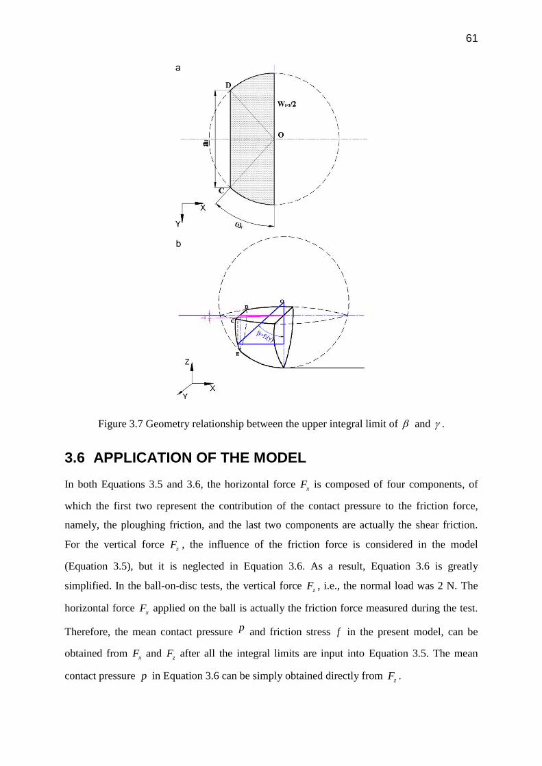
61
Figure 3.7 Geometry relationship between the upper integral limit of and .
3.6 APPLICATION OF THE MODEL
In both Equations 3.5 and 3.6, the horizontal force xF is composed of four components, of
which the first two represent the contribution of the contact pressure to the friction force,
namely, the ploughing friction, and the last two components are actually the shear friction.
For the vertical force zF , the influence of the friction force is considered in the model
(Equation 3.5), but it is neglected in Equation 3.6. As a result, Equation 3.6 is greatly
simplified. In the ball-on-disc tests, the vertical force zF , i.e., the normal load was 2 N. The
horizontal force xF applied on the ball is actually the friction force measured during the test.
Therefore, the mean contact pressure p and friction stress f in the present model, can be
obtained from xF and zF after all the integral limits are input into Equation 3.5. The mean
contact pressure p in Equation 3.6 can be simply obtained directly from zF .

62
3.6.1 Ploughing and shear friction coefficients
Figure 3.8 shows the shear friction coefficient values obtained from the model based on
Equation 3.5 at different laps of wear. The differences between the apparent friction
coefficients measured during the tests and the shear friction coefficients calculated give the
values of the ploughing friction coefficient. It is obvious that the ploughing friction accounts
for a very small percentage (about 1 %) of the apparent friction, while the shear friction plays
a dominant role in determining the apparent friction. With increasing wear lap, both shear
friction and ploughing friction coefficients increase gradually. Figure 3.8 also compares the
shear friction coefficients obtained from Equation 3.6. There are indeed differences in the
shear friction coefficient values obtained from Equation 3.5 and Equation 3.6, although these
are not remarkable.
Figure 3.8 Shear friction coefficients and ploughing friction coefficients calibrated from
Equations 3.5 and 3.6.
Apparent µ
µshear calibrated from Eq.3.5
µshear calibrated from Eq.3.6
µploughing calibrated from Eq.3.5
µploughing calibrated from Eq.3.6

63
3.6.2 Mean contact pressure
Figure 3.9 shows the variation of the mean contact pressure with the lap of wear over a range
between the 10th and 50th laps. It is clear that regardless of the model used (Equation 3.5 or
Equation 3.6), the mean contact pressure decreases significantly with increasing wear lap or
the distance covered during the ball-on-disc tests. Under the same normal load of 2 N, the
mean contact pressure decreased, for example, from 47 MPa at the 10th lap to 19 MPa at the
50th lap. It is also obvious from Figure 3.9 that the differences in the mean pressure values
obtained from Equation 3.5 and Equation 3.6 are negligible.
Figure 3.9 Mean contact pressure determined from Equations 3.5 and 3.6.
3.6.3 Comparison between Equation 3.5 and Equation 3.6
From Figures 3.8 and 3.9, it appears that Equations 3.5 and 3.6 give quite similar shear
friction coefficient values and mean pressure values. Actually, the horizontal force in both
Equations 3.5 and 3.6 can be simplified to be:
x plowing shear plowing s z plowing s nF f f f F f ps (3.14)
wherens is the normalized area. In principle, the values of
zF calculated using Equations 3.5
and 3.6 should both be consistent with the normal load applied in the tests, i.e., 2 N. Figure
Eq.3.5
Eq.3.6

64
3.10 shows the normal load values calculated from these two models. The model extended
from Tayebi‟s model, i.e. Equation 3.5, gives the values in the range of 2.03 to 2.05 N, which
is in good agreement with the normal load applied. The error is about 3.5 %, which may stem
from the limit of the numerical integration tolerance. However, the normal load values
obtained from Equation 3.6 are in the range of 1.82 to 1.87 N. The larger deviations of almost
10% from the normal load applied may be attributed to the underestimation of the normalised
contact area ns [15]. Therefore, the model (Equation 3.5), although more complex than
Equation 3.6, is preferable for the determination of the ploughing friction and shear friction as
well as mean pressure during high-temperature ball-on-disc tests.
Figure 3.10 Normal load calculated using Equation 3.5 and Equation 3.6.
3.7 CONCLUSIONS
A model capable of determining the ploughing friction and shear friction as well as the mean
contact pressure during high-temperature ball-on-disc tests was developed on the basis of
Tayebi‟s model for scratch tests. Considering the ball perfectly rigid and the disc perfectly
plastic or elasto-plastic in ball-on-disc tests, the integral limits for the solution of the model
could be obtained from the evolving wear track. The forces acting on the ball surface could be
reproduced by integration. During the ball-on-disc tests with a steel ball sliding on an
Eq.3.5
Eq.3.6

65
aluminium disc at 450 °C, the ploughing friction accounted for only about 1 % of the apparent
friction, although the ploughing friction coefficient tended to increase with increasing wear
lap, while the shear friction played a dominant role in determining the apparent friction. The
mean contact pressure decreased significantly over a range of wear laps till 50. The model
extended from Tayebi‟s model for scratch tests gives quite similar values of the shear friction
coefficient and the mean pressure values to those from Goddard‟s model. However, the
former is preferable, as the latter underestimates the normalised contact area.
References
[1] Y. T. Pei, P. Huizenga, D. Galvan, and J. T. M. De Hosson, "Breakdown of the
Coulomb friction law in TiC/a-C : H nanocomposite coatings," Journal of Applied
Physics, vol. 100, p. 9, Dec 2006.
[2] E. Badisch, G. A. Fontalvo, M. Stoiber, and C. Mitterer, "Tribological behavior of
PACVD TiN coatings in the temperature range up to 500 degrees C," Surface &
Coatings Technology, vol. 163, pp. 585-590, Jan 2003.
[3] F. P. Bowden and D. Tabor, The friction and lubrication of solids. Oxford,: Clarendon
Press, 1950.
[4] J. L. Bucaille, E. Felder, and G. Hochstetter, "Mechanical analysis of the scratch test
on elastic and perfectly plastic materials with the three-dimensional finite element
modelling," Wear, vol. 249, pp. 422-432, Jun 2001.
[5] S. Lafaye, C. Gauthier, and R. Schirrer, "The ploughing friction: analytical model with
elastic recovery for a conical tip with a blunted spherical extremity," Tribology Letters,
vol. 21, pp. 95-99, Feb 2006.
[6] J. D. Kamminga and G. Janssen, "Experimental discrimination of ploughing friction
and shear friction," Tribology Letters, vol. 25, pp. 149-152, Feb 2007.
[7] N. P. Suh, Tribophysics. Englewood Cliffs, N.J.: Prentice-Hall, 1986.
[8] C. Gauthier, S. Lafaye, and R. Schirrer, "Elastic recovery of a scratch in a polymeric
surface: experiments and analysis," Tribology International, vol. 34, pp. 469-479, Jul
2001.
[9] S. Lafaye, C. Gauthier, and R. Schirrer, "A surface flow line model of a scratching tip:
apparent and true local friction coefficients," Tribology International, vol. 38, pp. 113-
127, Feb 2005.

66
[10] Z. Liu, J. Sun, and W. Shen, "Study of ploughing and friction at the surfaces of plastic
deformed metals," Tribology International, vol. 35, pp. 511-522, Aug 2002.
[11] N. Tayebi, T. F. Conry, and A. A. Polycarpou, "Determination of hardness from
nanoscratch experiments: Corrections for interfacial shear stress and elastic recovery,"
Journal of Materials Research, vol. 18, pp. 2150-2162, Sep 2003.
[12] L. Wang, Y. He, J. Zhou, and J. Duszczyk, "Effect of temperature on the frictional
behaviour of an aluminium alloy sliding against steel during ball-on-disc tests,"
Tribology International, vol. 43, pp. 299-306, Jan-Feb 2010.
[13] V. Hegadekatte, N. Huber, and O. Kraft, "Modelling and simulation of wear in a pin
on disc tribometer," Tribology Letters, vol. 24, pp. 51-60, Oct 2006.
[14] J. R. Jiang and R. D. Arnell, "On the running-in behaviour of diamond-like carbon
coatings under the ball-on-disk contact geometry," Wear, vol. 217, pp. 190-199, May
1998.
[15] K. Komvopoulos, "Sliding friction mechanisms of boundary-lubricated layed surfaces.
2. Theoretical analysis," Tribology Transactions, vol. 34, pp. 281-291, Apr 1991.
[16] J. Goddard and H. Wilman, "A theory of friction and wear during the abrasion of
metals," Wear, vol. 5, pp. 114-135, 1962/4//.

67
Chapter 4
DETERMINATION OF FRICTION COEFFICIENT
FOR THE BEARING CHANNEL OF THE HOT
ALUMINIUM EXTRUSION DIE
ABSTRACT
Appropriate specification of the frictional boundary condition for the finite element (FE)
simulation of metal-forming processes is of great importance to the trustworthiness of the
results. The research reported in this chapter aimed at understanding the interfacial contact
between aluminium and steel at elevated temperatures and determining friction coefficients at
this material mating. A series of high-temperature ball-on-disc tests were carried out with the
AA7475 aluminium alloy as the material of disc and the hardened H11 steel as the material of
ball. A mathematical model for high temperature ball-on-disc test developed in the preceding
chapter was employed to account for the evolution of the contact interface during ball-on-disc
tests. Friction coefficients at different temperatures and over a number of laps were
determined. The shear friction stresses and mean contact pressures along with the progress of
the tests at 350 – 500 °C were calculated. It was found that the friction coefficients obtained
from ball-on-disc tests alone were insufficient to represent the frictional interaction between
deforming aluminium and steel at elevated temperatures. The evolution of the contact
interface with increasing sliding distance must be taken into consideration and the friction
behaviour can be reasonably characterized by using friction stress. In addition, a physically
based friction model was developed based on the temperature dependent friction stress results.
This chapter is reproduced from the article published in Tribology Letters, vol. 36, pp. 183-190, Nov 2009.

68
4.1 INTRODUCTION
The contact at the billet/die bearing interface where the extruded product is shaped is of vital
importance for the product quality and die life. Preceding research using both the
experimental approach and FE simulation [1-3] have shown that, being similar to the
machining process [4], a transition from sticking to sliding takes place in the die bearing
channel and thus the friction coefficients representing the change in friction mode must be
incorporated into FE simulation. In addition, physical simulations, such as ring compression
tests at room temperature [5] and block-on-disc tests at elevated temperatures [6] have been
performed to characterize the tribological interactions between aluminium and steels. More
recently, first attempts have been made to determine the friction coefficients between hot
aluminium and steel by means of ball-on-disc tests during which conform contact between the
deforming disc and ball is gradually established, which is closer to the actual contact at the die
bearing during extrusion [7, 8].
Ball-on-disc test is one of the most commonly used methods for characterizing the
tribological properties of the materials at contact. However, the friction coefficients obtained
from ball-on-disc tests have not yet been implemented in the FE simulation of aluminium
extrusion, due to a lack of the methodology for translating the data from ball-on-disc tests to
the extrusion process. In the preceding chapter, a model capable of revealing the features of
the contact interface during high-temperature ball-on-disc tests and discriminating between
the ploughing friction and shear friction was developed [7]. The objective of the present
chapter was to implement this model in practical contact situations between hot aluminium
and H11 tool steel during ball-on-disc testing, and the results were expected to be extracted to
define the frictional boundary condition for the FE simulation of the aluminium extrusion
process.
4.2 MATERIALS AND EXPERIMENTAL PROCEDURE
In the present chapter, the high-strength AA7475 aluminium alloy disc had a thickness of 5
mm and a diameter of 49 mm. The surface of the disc with a hardness value of 53 HRA at
room temperature was polished to an average roughness Ra of 33 nm. The H11 hot-work tool
steel hardened to a hardness value of 53 HRC at room temperature was selected as the mating
material. The ball had a diameter of 5 mm, and an average roughness of 209 nm. The
compositions of the materials used in the present chapter are given in Table 4.1.

69
Table 4.1 Compositions of H11 hot-work steel and AA7475 aluminium alloy (wt.%).
H11
steel
C Cr Mn Mo Si V Fe
0.40 5.0 0.30 1.30 1.0 0.50 Balance
AA7475
Si Fe Cu Mn Mg Cr Zn Ti Al
0.10 0.12 1.9 0.06 2.4 0.18 5.2 0.06 Balance
A CSM® high-temperature tribometer with a ball-on-disc rig was used for a series of short-
distance high-temperature friction tests in order to reach the solutions of the model developed.
The radius of the wear track was 6 mm and the linear speed was 2 mm/s. The tests were
carried out under a constant normal load of 6 N at 350, 400, 450 and 500 °C in the ambient
atmosphere. Three tests with different wear laps (1, 5 and 10 laps) were carried out at each
temperature. The short-distance tests under the relatively high normal load were desired to
produce high contact pressures up to 120 MPa, which would resemble the situation in the
bearing channel of the extrusion die during lab-scale extrusion experiments where the normal
pressure varied from two to six times of the flow stress of the billet material. The friction
coefficient was continuously registered during the test. Thereafter, wear tracks were examined
using an optical microscope. The average width of the wear track in each lap was determined
from 12 measurements.
4.3 RESULTS AND DISCUSSION
4.3.1 Evolution of friction coefficient with sliding distance
Figure 4.1 shows the evolution of the friction coefficient over a sliding distance of 10 laps at
different temperatures. It is of interest to note that friction coefficient increases with the
sliding distance. At 500 °C, in particular, the friction coefficient increases even by 50%. The
significant variation of the friction coefficient with sliding distance during the ball-on-disc
tests was also observed by other researchers [8], and this phenomenon was attributed to the
material transfer and back transfer which significantly altered the contact interface topography
and changed the real contact area. However, in the present chapter, short distance friction tests

70
(10 laps of sliding) were performed and the friction coefficients were found to increase
steadily with the sliding distance, and thus the explanation [8] may not applicable. At the
beginning stage of testing, the contact pressure was very high, and severe plastic deformation
and drastic removal of surface material occurred. As shown below, the increase of friction
coefficient with sliding distance appears to be accompanied by the increase in apparent
contact area during the running-in period. Their correlation appears to be peculiar and occurs
in the material mating at high temperatures with involvement of strong adhesion. The
evolution of the friction coefficient with sliding distance, as shown in Figure 4.1, leads to the
uncertainty as to the exact value to be put into FE simulation. It is therefore necessary to have
a model with which the friction coefficient and sliding distance are correlated with each other.
In the present chapter, the friction coefficients and residual widths of wear tracks determined
during and after the ball-on-disc tests were used as input data of the model, i.e. Equations 3.2,
3.3 and 3.4. The evolutions of the contact area and shear friction stress were obtained.
4.3.1.1 Evolution of wear track width
An average value of the widths of wear tracks was determined from 12 measurements by
using an optical microscope. The residual width of the wear tracks can be fitted:
b
iW a i (4.1)
where iW is the width of the wear track after the i th lap of wear, and a and b are constants.
Figure 4.2 shows the experimental and fitted results of the widths of wear tracks. As can be
seen, the widths of wear tracks increase steadily with increasing sliding distance and testing
temperature. This can be explained by Holm and Archard‟s equation as given below [9, 10].
During the ball-on-disc tests between aluminium and hardened tool steel at elevated
temperatures, it is reasonable to assume the ball material (hardened steel) behaves as a rigid
material. Therefore, the amount of wear on the disc surface is proportional to the normal load
and sliding distance/laps of sliding and inversely proportional to the surface hardness of the
disc material, i.e.
kWx
vH
(4.2)
where v is the total volume of wear; W the applied normal load; x the total sliding distance
and H the surface hardness of the material. Obviously, the more laps of sliding, the larger

71
amount of wear, or wider and deeper wear track will be. In addition, the hardness of the disc
material decreases significantly with increasing temperature, thus wider wear tracks are
formed at higher temperatures, as the experiments show (Figure 4.2).
0 1 2 3 4 5 6 7 8 9 10 110.00
0.25
0.50
0.75
1.00
1.25
1.50
1.75
2.00
2.25
350oC H11 steel ball
Fri
ctio
n c
oe
ffic
ien
t
Laps of wear
0 1 2 3 4 5 6 7 8 9 10 110.00
0.25
0.50
0.75
1.00
1.25
1.50
1.75
2.00
2.25
400oC H11 steel ball
Fri
ctio
n c
oe
ffic
ien
t
Laps of wear
(a) (b)
0 1 2 3 4 5 6 7 8 9 10 110.00
0.25
0.50
0.75
1.00
1.25
1.50
1.75
2.00
2.25
450oC H11 steel ball
Fri
ctio
n c
oe
ffic
ien
t
Laps of wear
0 1 2 3 4 5 6 7 8 9 10 110.00
0.25
0.50
0.75
1.00
1.25
1.50
1.75
2.00
2.25
500oC H11 steel ball
Fri
ctio
n c
oe
ffic
ien
t
Laps of wear
(c) (d)
Figure 4.1 Evolution of the friction coefficient with increasing sliding distance at
different temperatures.

72
2 4 6 8 100
100
200
300
400
500
600
700
800
900
Wid
th o
f w
ea
r tr
acks (m
)
Residual width of wear tracks
Exp. 350oC
Exp. 400oC
Exp. 450oC
Exp. 500oC
Laps of wear
Figure 4.2 Evolution of the width of wear tracks with sliding distance.
4.3.1.2 Evolution of contact area and mean contact pressure
Figure 4.3 shows the evolution of the apparent contact area during ball-on-disc testing. Due to
the removal of the surface material, the wear track becomes wider and the contact area indeed
increases with the sliding distance. According to Bowden and Tabor‟s classical theory of
friction [11], the friction coefficient increases with increasing real contact area. In the present
research, aluminium was so soft that severe plastic deformation occurred on the contact
interface and the real contact area increases as the apparent contact area increases. Therefore,
it is the increasing contact area with the laps of sliding that results in the increasing friction
coefficient as shown in Figure 4.1.
Figure 4.4 shows the evolution of mean contact pressure on the contact interface. As a result
of the increasing contact area, the mean contact pressure decreases with increasing sliding
distance.
During the ball-on-disc tests, contact area, mean contact pressure and the friction coefficient
varied considerably. Therefore, friction coefficient alone may be insufficient to characterize
the friction properties of the mating materials. Friction stress that is the friction force per unit
area may be a better option, because it is convenient for the characterization of the friction at
the interface involving strong adhesion without specifying the real contact area. It is certainly
necessary to understand the evolution of the friction stress further during prolonged pin-on-
disc tests.

73
0 2 4 6 8 10 12
0.03
0.04
0.05
0.06
0.07
0.08
350oC
400oC
450oC
500oC
Co
nta
ct
are
a (
mm
2)
Laps of wear
Figure 4.3 Evolution of the apparent contact area with sliding distance.
0 2 4 6 8 10 1260
90
120
150
180
210
350oC
400oC
450oC
500oC
Me
an
co
nta
ct
pre
ssu
re (
MP
a)
Laps of wear
Figure 4.4 Evolution of the mean contact pressure with sliding distance.

74
4.3.2 Evolution of shear friction stress
2 4 6 8 100
50
100
150
200
250
300
350
350oC
400oC
450oC
500oC
Sh
ea
r fr
ictio
n s
tre
ss (
MP
a)
Laps of wear
Figure 4.5 Evolution of the shear friction stress with sliding distance.
Figure 4.5 shows the evolutions of the calculated shear friction stress at different temperatures
and over a sliding distance of 10 laps. It is interesting to see that the shear friction stress starts
from a relatively low value, and then becomes quite stable at each of the temperatures, while
the friction coefficient increases considerably (Figure 4.1). The low shear friction stress at the
initial stage may be due to the oxide layer on the disc and ball surfaces, which tends to lower
the adhesion between aluminium and steel [12, 13]. After the initial stage of sliding, the oxide
layer may be broken up and metal-to-metal contact occurs, leading to the increases in friction
stress. In addition, the severe plastic deformation on the surface material may generate a
considerable work-hardening effect [11, 14], which may also lead to the rise of shear friction
stress. As can be seen from Figure 4.5, the shear friction stress differs markedly at different
temperatures, and it is therefore necessary to reveal the influence of temperature on the
friction stress.
4.3.3 Influence of temperature on the shear friction stress
Figure 4.6 shows the correlation of the mean shear friction stress with temperature. It has been
used as a base to develop a novel friction model. From Figure 4.6, it is clear that the friction
stress decreases steadily with increasing temperature. This is consistent with the observations

75
made during the machining process [15] and the results of the friction tests carried out by
Bowden and Tabor [11]. It is however inconsistent with the results obtained by other
researchers from ball-on-disc tests at elevated temperatures [8]. Therefore, more efforts are
needed to explain the contradictory results and to reveal the real effect of temperature on
friction.
330 360 390 420 450 480 5100
30
60
90
120
150
180
210
240
270
300
330
Mea
n sh
ear
fric
tion
stre
ss (
MP
a)
Temperature (oC)
Figure 4.6 Mean shear friction stress as a function of temperature.
It is commonly understood that the friction force at elevated temperatures stems from the
deformation of surface material and the adhesive bonding of the contact joints [11, 16, 17]. As
temperature increases, the friction force due to the deformation of the asperities decreases
significantly because of the softening effect of the surface material. On the other hand, the
adhesive friction plays an increasing important role in determining the overall friction,
because the mating materials tend to be more active at elevated temperatures.
At elevated temperatures, the mating materials tend to be more active to generate adhesive
bonding between each other, but an increase in friction coefficient may not necessarily appear,
because the overall friction coefficient will be determined by many factors, for example, the
adhesive strength and real contact area. As temperature increases, the strength of the adhesive
joints decreases significantly and thus the friction coefficient tends to decrease. It is however
important to note that during the high-temperature ball-on-disc tests the area of the contact

76
interface increases with the sliding distance, which may be different from other types of
friction tests. This may increase the number of adhesive joints due to strong adhesion and thus
the friction force. Further studies are needed on the physical and chemical tribology of the
mating surfaces at elevated temperatures to clarify the correlation between the apparent
contact area and friction coefficient under this special circumstance. In addition, the increase
of the friction coefficient may be partly caused by hard wear debris generated due to oxidation
and entrapped at the interface, because the tests were carried out in the ambient atmosphere
and as such the influence of a hard aluminium oxide layer on friction coefficient would be
inevitable. The combination of these factors complicates the results of ball-on-disc tests. As a
consequence, incomparable results might be obtained from the ball-on-disc tests, as compared
to other friction testing methods and friction coefficient alone is most likely insufficient to
characterize the interface friction property, when ball-on-disc tests are used. It would be
necessary to take the evolution of the contact area/normal pressure into account as well and
friction stress might be a better option.
4.4 PHYSICALLY-BASED ADHESIVE STRENGTH FRICTION
MODEL (ASFM) FOR THE BEARING CHANNEL OF HOT
ALUMINIUM EXTRUSION DIE
According to the classic theory of tribology, friction force mainly stems from ploughing (due
to hard asperities and trapped wear debris) and adhesive (due to atomic or chemical
interactions) forces [11, 14, 17]. At high temperatures, the adhesive friction plays an
important role, due to the strong atomic or chemical interactions, especially under high
contact pressures [6, 18]. This is mainly due to the following reasons: at elevated
temperatures, the atoms in both of the contact materials are highly activated, which aids
interdiffusion at the surface layers of the materials and a strong chemical bonding tends to be
established. On the other hand, the mating materials and surface oxides are relatively soft and
easy to be deformed. In addition, the high contact pressure (several times higher than the flow
stress of the work piece material) further aids the severe plastic deformation of the asperities
or oxidation scale, and brings the faying material highly close to each other to a distance of
atomic level. Therefore, in the bearing channel of hot aluminium extrusion, the strong
chemical or diffusion bonding is the dominant friction mechanism. Consequently, the strength
of adhesive junctions can be determined by two factors, namely, the rate of atomic interaction
and the strength of adhesive joints (Equation 4.3). The interaction rate at atomic level

77
increases with increasing temperature, which can be modelled by using an Arrhenius type
equation [19] (Equation 4.4). Meanwhile, the bonding strength decreases with increasing
temperature, due to the decrease of material strength with increasing temperatures, and the
bonding strength drops to zero at the melting temperature of AA7475. In the present study, in
order to determine the constants of the model, short distance ball-on-disc test results were
used as the friction stress at different temperatures. Table 4.2 lists the determined material
constants. As can be seen from Figure 4.7, a good agreement between the model and
experimental results was obtained.
0 1m
Tf T f D
T
(4.3)
0 exp DQ
D DRT
(4.4)
where f T is temperature dependant bonding strength or friction stress; 0f is the initial
adhesive strength at room temperature (300 K ); D is the inter-diffusion coefficient; T is the
mean contact temperature ( K ); mT is the melting temperature of the work piece material ( K );
DQ is the activation energy; R is the universal gas constant; 0D and are constants;
550 600 650 700 750 800 8500
50
100
150
200
250
300
350
400 Exp.
Me
an
sh
ea
r fr
ictio
n s
tre
ss (
MP
a)
Temperature (K)
Predicted

78
Figure 4.7 Evolution of friction stress between AA7475 and H11 steel at different
temperatures.
Table 4.2 Material constants of the ASFM for hot AA7475 and H11 steel.
0f (MPa) mT ( K ) DQ (J/mol) R(J/K/mol) 0D
378 811 2400 8.314 3.62 0.7
As can be seen from Figure 4.7, the bonding strength is determined by the combined effects
of atomic interaction and material strength. Under the high temperature condition, the
bonding strength decreases with increasing temperature, because the drop of material strength
plays a dominant role, although the atoms are highly activated and atomic interactions are
more intensive. Therefore a decreased adhesive strength with the increasing temperature can
be observed, which is consistent with other research results [11, 15].
4.5 CONCLUSIONS
A series of ball-on-disc tests were carried out at different temperatures. The friction
coefficients were found to increase with increasing sliding distance. The individual friction
coefficient data could not be utilized directly for FE simulation of the aluminium extrusion
process. A model for ball-on-disc tests, developed in the preceding chapter, was used to reveal
the contact between aluminium and tool steel at elevated temperatures. The calculated shear
friction stress and mean contact pressure showed that, during the running-in period, the shear
friction stress was quite stable, while the friction coefficient increased with increasing sliding
distance significantly. Therefore, a fundamental understanding of the evolution of the contact
interface must be gained, before the results of ball-on-disc tests can be used as the frictional
boundary conditions for FE simulation.
References

79
[1] W. W. Thedja, Müller, K.B., Ruppin D., "Tribomechanical process on the die land
area during extrusion of AA6063 alloy," in the 5th International Aluminium Extrusion
Technology Seminar, 1992, pp. 467-474
[2] S. Tverlid, "Modelling of friction in the bearing channel of dies for extrusion of
aluminium sections," vol. PhD thesis, 1997.
[3] T. A. Welo, S.; Skauvik, I.; Støren, S.; Melander, M.; Tjøtta, S., "Friction in the
bearing channel of aluminium extrusion dies," in 15th Riso International Symposium
on Materials Science, Roskilde, Denmark 1994, pp. 615-620.
[4] C. Bonnet, F. Valiorgue, J. Rech, C. Claudin, H. Hamdi, J. M. Bergheau, and P. Gilles,
"Identification of a friction model--Application to the context of dry cutting of an AISI
316L austenitic stainless steel with a TiN coated carbide tool," International Journal of
Machine Tools and Manufacture, vol. 48, pp. 1211-1223, 2008.
[5] A. Behrens and H. Schafstall, "2D and 3D simulation of complex multistage forging
processes by use of adaptive friction coefficient," Journal of materials processing
technology, vol. 80-1, pp. 298-303, Aug-Sep 1998.
[6] T. Björk, J. Bergstrom, and S. Hogmark, "Tribological simulation of aluminium hot
extrusion," Wear, vol. 224, pp. 216-225, Feb 1999.
[7] L. Wang, Y. He, J. Zhou, and J. Duszczyk, "Modelling of ploughing and shear friction
coefficients during high-temperature ball-on-disc tests," Tribology International, vol.
42, pp. 15-22, Jan 2009.
[8] S. Ranganatha, S. V. Kailas, S. Storen, and T. S. Srivatsan, "Role of temperature on
sliding response of aluminium on steel of a hot extrusion," Materials and
Manufacturing Processes, vol. 23, pp. 29-36, 2008.
[9] H. R., Electric Contacts. Stockholm: Almqvist and Wiksells, 1946.
[10] J. Archard, "Contact and Rubbing of Flat Surfaces," Journal of Applied Physics, vol.
24, p. 981, 1953.
[11] F. P. Bowden and D. Tabor, The friction and lubrication of solids. Oxford,: Clarendon
Press, 1950.
[12] A. R. Riahi and A. T. Alpas, "Adhesion of AA5182 aluminium sheet to DLC and TiN
coatings at 25 degrees C and 420 degrees C," Surface & Coatings Technology, vol.
202, pp. 1055-1061, Dec 2007.
[13] A. R. Riahi, A. Edrisy, and A. T. Alpas, "Effect of magnesium content on the high
temperature adhesion of Al-Mg alloys to steel surfaces," Surface & Coatings
Technology, vol. 203, pp. 2030-2035, Apr 2009.

80
[14] I. M. Hutchings, Tribology : friction and wear of engineering materials. Boca Raton:
CRC Press, 1992.
[15] A. Moufki, A. Molinari, and D. Dudzinski, "Modelling of orthogonal cutting with a
temperature dependent friction law," Journal of the Mechanics and Physics of Solids,
vol. 46, pp. 2103-2138, 1998.
[16] N. P. Suh, Tribophysics. Englewood Cliffs, N.J.: Prentice-Hall, 1986.
[17] B. Bhushan, Introduction to tribology. New York: John Wiley & Sons, 2002.
[18] T. Björk, R. Westergård, and S. Hogmark, "Wear of surface treated dies for
aluminium extrusion -- a case study," Wear, vol. 249, pp. 316-323, 2001.
[19] M. Ghosh, K. Bhanumurthy, G. B. Kale, J. Krishnan, and S. Chatterjee, "Diffusion
bonding of titanium to 304 stainless steel," Journal of Nuclear Materials, vol. 322, pp.
235-241, 2003.

81
Chapter 5
DOUBLE ACTION EXTRUSION - A NOVEL
EXTRUSION PROCESS FOR FRICTION
CHARACTERIZATION AT THE BILLET DIE
BEARING INTERFACE
ABSTRACT
A novel extrusion testing method, double action extrusion (DAE), to highlight the effect of
friction at the die bearing in aluminium extrusion was developed. It was found that the lengths
of the extrudates and extrusion force were indeed sensitive to the die bearing length and thus
to the friction. FEM simulations of DAEs were carried out to evaluate two commonly used
friction models. It was found that, when the extrusion dies with a 15‟choke angle were used,
full-sticking friction represents the experimental results the best. In addition, the physically-
based friction model (adhesive strength friction model: ASFM) developed in Chapter 3 was
implemented into the simulations of DAEs for model verification. Good agreements between
the FE predictions and experiments were obtained, indicating that ball-on-disc test is an effect
way of characterizing the friction for the bearing channel of extrusion dies. For a further
understanding of the DAE, a theoretical model was developed, and a good agreement between
the modelling results and experiments was obtained. The theoretical modelling results
revealed that the length difference of the extrudates was caused by the combined effects of
friction and material rate dependence at elevated temperatures.
This chapter is reproduced from the articles published in Tribology International, vol. 43, pp. 2084-2091, 2010 and Key Engineering Materials, vol. 424, pp. 153-160, 2010.

82
5.1 INTRODUCTION
For hot aluminium extrusion, the bearing channel area is of great importance, as it determines
the quality of the final products, but the assignment of friction coefficients within the bearing
channel remains a pure guess work, because the bearing area is relatively small compared to
the container area; therefore the change of friction condition within the bearing channel can
hardly be observed from the variation of the total extrusion load or the slope of the load-
displacement curve. In the past few years, the friction coefficient within the bearing channel
was studied by using extrusion tests [1-3]. Being similar to the different contact zones
observed from the metal cutting process [4-7], the presence of two or three different zones
were observed on the bearing surface of the extrusion dies, namely a full sticking zone close
to the die entrance and a sliding zone close to the die exit; when extruding at a lower die
temperature, a transition zone between the two zones could be observed. In some research
work [1-3], the lengths of sliding and sticking zones were considered friction sensitive, and
friction coefficients were thus obtained by measuring the lengths of sliding and sticking zones.
To avoid complications, the contact within the bearing channel has been simplified to be of
the sliding type and a constant friction factor ranging from 0.3 to 0.6 was used [8-11]. In the
present chapter, a novel simulative test, double action extrusion (DAE), highlighting the
friction in the bearing channel was developed [12], the tests were conducted on a Gleeble
3800 thermo-mechanical simulator, in which an aluminium billet was pressed against two
dies with different bearing lengths (2 mm and 6 mm). FEM simulations of DAE were carried
out to evaluate the Shear and Coulomb friction models over a wide range of friction
factors/coefficients from 0.2 to 1.
Although the DAE test has been found to be a friction sensitive process, the fundamental
mechanisms of this novel simulative test remain unclear. One of the main objectives of the
present chapter is to address the above issue by theoretical analysis, and to evaluate the
different friction models by using DAE tests and FEM simulations.
5.2 EXPERIMENTAL AND SIMULATION DETAILS
Figure 5.1 shows the schematic of DAE and the experimental setup. During the experiments
on a Gleeble thermomechanical simulator, an aluminium billet was pressed against two
extrusion dies with different bearing lengths (8 and 2 mm; 6 and 2 mm) simultaneously. A 15‟
chock angle was assigned to the bearing of the dies in order to enhance the effect of the
friction on the DAE results. It was expected that the differentiated lengths of the extrudates

83
passing these two bearing channels as well as the extrusion force could be used to characterize
the friction at the die bearing.
Aluminium alloy 7475 was used as the billet material. The extrusion tooling, i.e. two
extrusion dies with different bearing lengths and one container, was made of H11 hot-work
tool steel. Their physical properties are listed in Table 5.1, which were also used for the
parameters of FE analysis. Figure 5.2 shows the aluminium billet and extrusion tooling used
in the DAE experiments. The dimensions of the billet, extrusion dies and container, together
with the main process parameters, are listed in Table 5.2. The DAE experiments were carried
out at 350, 400 and 450 °C, which are the typical temperatures for hot aluminium extrusion.
The speed of the moving anvils was 1 mm/s.
(a) (b)
Figure 5.1 (a) Schematic and (b) experimental setup of double action extrusion (DAE).
Figure 5.2 Aluminium alloy billet and steel tooling used in the DAE experiments.

84
The materials of the aluminium billet shows thermo-viscoplastic behaviour as the forming
temperature was above 350 °C, while the material of extrusion tooling was considered as
thermo-rigid. The elastic behaviour of the materials was neglected. The flow stress/strain data
of the AA7475 alloy were determined from hot compression tests using a Gleeble 3800
thermo-mechanical simulator, after flow stresses at high strain rates were corrected for
deformational heating [13]. Flow stress – strain data over a temperature range of 250 – 500 °C
and a strain rate range of 0.01 – 10 s-1
were imported into DEFORM-3D as the material model
of the AA7475 alloy. The flow stress data was also used for the mechanical behaviour
modelling of AA7475 alloy in section 5.3.
Table 5.1 Physical properties of the AA7475 work piece and H11 tooling.
Property AA 7475 H11 tool steel
Heat capacity (J/kg/K) 2.43369
3.2 at 315 °C
4.5 at 540 °C
Thermal conductivity (W/m/K) 180.181 24
Heat transfer coefficient between tooling and
billet (W/K/m2)
11 11
Heat transfer coefficient between tooling/billet
and air (W/K/m2)
0.02 0.02
Emissivity 0.7 0.7
Table 5.2 Dimensions of the billet and DAE tooling as well as the main process parameters.
Billet length (mm) 15
Billet diameter (mm) 9.8
Container inside diameter (mm) 10
Container outside diameter (mm) 20

85
Die bearing length (mm) 2 and 8;2 and 6
Choke angle (min) 15
Reduction ratio 11
Initial billet temperature (°C) 350, 400 and 450
Initial tooling temperature (°C) 350, 400 and 450
Anvil speed (mm/s) 1
Figure 5.3 shows the FE model for the DAE. All the objects in the FEM model were meshed
with tetrahedral elements. In order to enhance the efficiency of the FEM simulations and the
accuracy in the areas of particular interest, a number of mesh windows with an increased
element density were applied around the die orifices to generate local finer elements. A
relative interference depth of 0.2 was defined to trigger the remeshing procedure.
The friction at the billet-container and billet-die face interfaces was considered to be of shear
type and a friction factor m = 1 used. Friction windows were applied at the work piece-die
bearing interface to make the friction boundary condition adjustable. Both the Shear friction
model and Coulomb friction model with friction factors/coefficients ranging from 0.2 to 1
were used in the FEM simulations to evaluate these friction models and determine the friction
factor/coefficient. The ASFM was implemented into DEFORM 3D V6.1 via user defined
subroutine. In DEFORM 3D version 6.1, to avoid the overestimation of the friction stress, the
value of the friction stress calculated from the Coulomb friction model was compared with the
shear flow stress of the work piece material at each iteration step and automatically changed
to the shear flow stress, if the calculated friction stress was larger than the shear flow stress. In
this way, the Coulomb friction model could be used in the FEM simulation of the aluminium
extrusion process at elevated temperatures.

86
Figure 5.3 FE model for the DAE.
5.3 THEORETICAL MODELLING OF DOUBLE ACTION
EXTRUSION
5.3.1 Theoretical background
Figure 5.4 shows the schematic of double action extrusion. The process can be considered as a
combination of two indirect extrusions. The work piece is divided into 5 zones according to
different deformation modes, namely, bearing area zone (zone 1 and zone 5), severe
deforming zone (zone 2 and zone 4) and rigid zone (zone 3). Plastic deformation occurred in
the bearing area zone and severe deforming zone due to the compression effect of the
extrusion dies and dead metal zone. During the double action extrusion, zone 3, moved
together with the container, thus it can be considered as a rigid zone.

87
(a) (b) (c) (d) (e)
Figure 5.4 Theoretical analysis of double action extrusion.
(a) Zone 1 and zone 5: bearing area
An elemental material of width dx was analysed (Figure 5.4 a). The forces acting on this
elemental material can be expressed as:
2 2
1 1 1 1 1sin cos2 2 cos cos
x x x
D dD D dx dxd P D D
(5.3.1-1)
According to the geometric relationship, cot2
dDdx . The Shear friction model was
used, i.e. 2
Ym . Thus,
2 cot lnxi i iY m D C ( i =1 or 5) (5.3.1-2)

88
(b) Zone 2 and zone 4: deforming zone
The dead metal zone builds up in the corners of the dies, which acts as a conical die surface,
therefore it can be considered as rigid during extrusion. An elemental material of width dx
was analysed (Figure 5.4 b). The forces acting on the elemental material can be expressed as:
2 2
2 2 2 2 2sin cos2 2 cos cos
x x x
D dD D dx dxd P D D
(5.3.1-3)
According to the geometric relationship, cot2
dDdx and during extrusion, shear
deformation occurred at the zone 2/dead metal zone interface, and thus2
Y . Therefore,
2 cot lnxj j jY D C ( j =2 or 4) (5.3.1-4)
(c) Zone 3: rigid zone
The work piece material moved together with the container and no plastic deformation
occurred, therefore the axial stresses acting on the zone 2/zone 3 and zone 3/zone 4 interfaces
should maintain a dynamic balance throughout the extrusion process.
In the present research, 2 10D mm and
0 3D mm , hence the extrusion ratio was 11
approximately. In addition, a constant ram speed ( 1 /v mm s ) was employed during the tests,
thus the extrusion speeds in the two bearing channels should always follow the rule:
5 1 11 /v t v t mm s (5.3.1-5)
where t is the extrusion time. 5v t and 1v t are the extrusion speeds at the die entrances of
zone 5 and zone 1, respectively. At the very initial stage of extrusion (t=0), we can safely
assume the initial extrusion speeds as : 5 10 0 5.5 /v v mm s .
The lengths of extruded profiles can be expressed as:
5 5
0
t
xL v t dt (5.3.1-6)

89
1 1
0
t
xL v t dt (5.3.1-7)
5.3.2 Integral constants determination
When the length of the extruded profile in zone 1 is1xL , (
10 8xL , and for the boundary
condition determination:1 8xL when
1 8xL , because the axial stress drops to zero as soon as
the profile is extruded out of the die) the diameter of the end of the profile in zone 1 is:
1 12 tanxD D L , and the boundary condition is: 1 0x , when
1 12 tanxD D L .
Consequently, 1C can be determined and the axial stress can be expressed as:
1 1
1 1
2 cot ln2 tan
x
x
DY m
D L
(5.3.2-1)
Identical situation happens in zone 5, when the extruded profile length is5xL (
50 2xL , and
for the boundary condition determination: 5 2xL when
5 2xL ), thus 5C can be determined
and the axial stress is:
5 5
3 5
2 cot ln2 tan
x
x
DY m
D L
(5.3.2-2)
In zone 2,2 1x x , when
2 3 4x L L L and1D D , hence
2C can be determined:
12 2 5
1 1 1
2 cot ln 2 cot ln2 tan
x
x
DDY Y m
D D L
(5.3.2-3)
Similarly, in zone 4, axial stress can be expressed as:
34 4 5
3 3 5
2 cot ln 2 cot ln2 tan
x
x
DDY Y m
D D L
(5.3.2-4)
In zone 3, a dynamic balance is established throughout the whole process of extrusion, which
is,
2 22 4x D D x D D
(5.3.2-5)

90
5.3.3 Material model for AA7475
The hyperbolic sine function proposed by Sellars and Tegart [14] and modified by Sheppard
and Wright [15] has been widely used to model the evolution of steady-state flow stress of
aluminium alloys. Therefore, Sellars and Tegart‟s model was employed:
1
11, sinh exp( )
nQ
Y TA RT
(5.3.3-1)
where Q is the activation energy, R is the universal gas constant and T is the temperature
( )K . Table 5.3 shows the values of the material constants. Figure 5.5 shows the comparison
between the calculated and experimental stress-strain curves at different testing temperatures
and strain rates, in which good agreements were obtained.
0 2 4 6 8 10 120
50
100
150
200
250
Str
ess (
MP
a)
Strain rate
523K
573K
623K
673K
723K
773K
Figure 5.5 Comparison of computed (solid curves) and experimental (symbols) stress-strain
relationship at different strain rates and testing temperatures.
Table 5.3 Material constants for AA7475.
1
(MPa) A (s
-1) n Q (J/mol) R (J/K/mol)
87.72 1027094727 5.41 129400 8.314

91
5.3.4 Strain rate determination
Strain rate can be determined by following the method introduced in [16]:
2
3
ivDd dD
dt D dx
( i =1 or 3) (5.3.4-1)
In zone 1: 2 tandD
dx ,
Therefore,
2 2
1 1 1 1
1 33
1 2 3 4
2 tan2 tan
2 tan
v t D v t D
D D L L L x
(5.3.4-2)
In zone 2: 2 tandD
dx ,
Therefore,
2 2
1 1 1 1
2 33
1 2 3 4
2 tan2 tan
2 tan
v t D v t D
D D L L L x
(5.3.4-3)
In zone 5: 2 tandD
dx ,
Therefore,
2 2
5 3 5 3
5 33
3
2 tan2 tan
2 tan
v t D v t D
D D x
(5.3.4-4)
In zone 4: 2 tandD
dx ,
Therefore,
2 2
5 3 5 3
4 33
3
2 tan2 tan
2 tan
v t D v t D
D D x
(5.3.4-5)
During the DAE, two indirect extrusions occurred simultaneously, thus it is reasonable to
assume that . The DAE tests were carried out on a Gleeble thermo-mechanical simulator,
and the aluminium billet temperature was accurately controlled by a feedback control system,
therefore the temperature of the work piece was assumed as constant during the tests.

92
5.3.5 Governing equations
The governing equations were solved using a FORTRAN program with full sticking condition
( m =1) along the container wall and the extrusion die assumed. The instantaneous extrusion
speeds 1v t and 5v t were determined from (5.3.5-1) to (5.3.5-6), and a time increment of
0.0001 s was used to update the lengths of the extrudates by using (5.3.5-7) and (5.3.5-8).
2 22 4x D D x D D
(5.3.5-1)
12 2 5
1 1 1
2 cot ln 2 cot ln2 tan
x
x
DDY Y m
D D L
(5.3.5-2)
34 4 5
3 3 5
2 cot ln 2 cot ln2 tan
x
x
DDY Y m
D D L
(5.3.5-3)
d
dt
(5.3.5-4)
1
11, sinh exp( )
nQ
Y TA RT
(5.3.5-5)
5 1 11 /v t v t mm s (5.3.5-6)
1 1
0
t
xL v t dt (5.3.5-7)
5 5
0
t
xL v t dt (5.3.5-8)
5.4 RESULTS AND MODEL VERIFICATION
5.4.1 Typical DAE results
Figure 5.6 shows a typical result of DAE. During the DAE tests, the aluminium billet was
pressed against two extrusion dies and extrusion in the indirect mode took place
simultaneously through these two dies. The friction force for the extrudate to flow through the
die with a bearing length of 8 mm was greater than that through the die with a bearing length

93
of 2 mm, as soon as the extrudate flew through the die with a shorter bearing length. As a
result, the lengths of the extrudates were significantly different due to the sensitivity of
extrusion speed to the friction force at the die bearing.
Figure 5.6 A typical DAE result with different extrudate lengths.
Figure 5.7 shows the measured extrusion forces, when DAE was performed at 350, 400 and
450 ºC. As can be seen in the figure, the extrusion forces decrease markedly with increasing
temperature, mainly due to decreasing flow stress of the work piece material with rising
temperature. The extrusion forces at these temperatures show a similar trend, i.e. a small
plateau at the very early stage, followed by a sharp increase in extrusion force and then a
gentle decrease as the process proceeded further. The small plateau corresponds to the
initiation of extrusion toward both of the dies (upsetting), and the sharp force increase
corresponds to breakthrough. In DAE, there is no relative movement and hence no dynamic
friction between the billet and container and therefore the extrusion force in the steady state
reflects the dynamic balance of the billet material (work hardening and dynamic recovery or
dynamic recrystallization) which is governed by temperature and influenced by the
temperature evolution during DAE.

94
0 1 2 3 4 5 6 70
10
20
30
40
50
60
Ext
rusi
on fo
rce
(kN
)
Ram displacement (mm)
350oC
400oC
450oC
Figure 5.7 Extrusion forces measured during the DAE experiments at different temperatures.
5.4.2 Steady-state extrusion force
Figure 5.8 shows the steady-state extrusion forces at different extrusion temperatures. The
extrusion force decreases with increasing temperature as a result of material softening at
higher temperatures. Of more interest is the comparison in the experimentally measured
extrusion forces and those predicted on the basis of the Shear and Coulomb friction models at
different friction factors/coefficients. It can be seen that both of the models show a similar
trend as the experimental results in terms of the effect of temperature on the extrusion force.
However, the extrusion forces predicted vary over a wide range, as a result of different
friction conditions assigned. From Figure 5.8, it appears that the shear friction model at m = 1
yields the extrusion forces the closest to the experimental measurements, although the
predicted value is 12% higher than the experimental one at 450 °C. The predicted steady-state
extrusion force decreases with decreasing friction factors, and the FEM results with a friction
factor of 0.6 is presented in Figure 5.8, which shows a deviation of over 16% from the
experimental data, suggesting that the widely used constant friction factor ranging between
0.3 and 0.6 might be too low in terms of extrusion force prediction. It can be seen from Figure
5.8 that the prediction from the ASFM shows the same trend as the experimental results in
terms of the temperature effect on the extrusion force and a fairly good agreement between
the FE predictions and experimental results was achieved.

95
Figure 5.8 Steady-state extrusion forces at different extrusion temperatures.
A deviation of 12% or smaller can be observed when Coulomb friction model at µ = 1 used,
which is still acceptable. At the other friction conditions, however, the predicted extrusion
forces are all much lower than the experimental results. It is clear that the steady-state
extrusion force is indeed highly sensitive to the friction at the die bearing in DAE. In the
present DAE tests, the full sticking friction describes the friction boundary condition at the
die bearing the best.
5.4.3 Extrudate lengths and validation of theoretical model
Figures 5.9, 5.10 and 5.11 show the comparison of the DAE experiments, FE simulations and
the theoretical model, in terms of the extrudate lengths. The relative lengths of the extrudates
are not very sensitive to temperature. As soon as the extrudate is out of the 2 mm long die
bearing, the extrudate lengths start to diverge. In other words, when the extrusion process
proceeds, the difference in extrudate length becomes greater. Obviously, the friction force at
the bearing channel plays a decisive role in the DAE process, and DAE is indeed sensitive to
friction in terms of extrudate lengths. On the other hand, AA7475 shows rate dependence at
elevated temperatures and this was the main factor to diminish the extrudate length difference.
During the DAE testing, since the extrusion speed is higher in the 2 mm bearing die, the
higher strain rate increases the flow stress of the material around the die orifice. Therefore a

96
higher force is required to deform the material around this area. On the other hand, the
extrusion speed in the 8 mm bearing die was lower compared to that in the 2 mm bearing die,
consequently, the material around the 8 mm bearing die was deformed at a relatively lower
strain rate, thus the material was soft and easy to deform. Therefore, the combined effects of
friction and material rate dependence led to a dynamic balance during DAEs.
As can be seen from Figures 5.9, 5.10 and 5.11, the FEM predictions of the extrudate lengths
based on the ASFM and the Shear and Coulomb friction models over a wide range of friction
factors/coefficients are presented together with the experimental results. At these three
extrusion temperatures, the Coulomb friction model at µ = 1 gives the most accurate
predictions of the extrudate lengths. The predicted lengths of the extrudates are not very
sensitive to the friction coefficients since the shear flow stress of the work piece is low
compared to the calculated friction stress. Also, the novel friction model (ASFM) leads to
highly accurate results in terms of extrudate lengths. The predictions of the shear friction
model at m = 1 are quite accurate as well, although small deviations from the experimental
measurements can be found at high temperatures. These deviations may be partly caused by
the errors of numerical iterations. Nevertheless, the deviations from the experimental data
increase markedly when lower friction factors are selected and the results of the present
research clearly indicate that a friction factor in the range from 0.3 to 0.6 often assumed at the
die bearing during aluminium extrusion may be too low and the friction in the die bearing
channel may be better represented by using the sticking boundary condition.
The extrudate lengths predicted by the theoretical model have shown great agreements with
the experimental data and the fundamental understanding of this novel process was obtained.
During DAE, the material flow is controlled by two main factors, namely, the friction force
within the die bearings, and the deforming force of the work piece material. At the initial
stage of extrusion, the work piece is extruded at the same extrusion speed in both of the dies.
With the increasing length of the extrudates, the friction forces increase at the same rate, due
to the increasing contact area. As soon as the profile has been fully extruded out of the 2 mm
bearing die, the friction within the 2 mm bearing die reaches its maximum value and will not
be further increased; on the other hand, the friction force increases in the 8 mm bearing die as
the extrudate length increases, therefore the extrusion speed in the 8 mm bearing die is slowed
down. Since the extrusion ratio always remains constant (Ratio ≈ 11) during the DAEs, the
extrusion speed in the 2 mm bearing die must be increased, which enhances the strength of the
work piece material around the 2 mm bearing die, and the increased deforming force balances

97
the extra friction force from the 8 mm bearing die. In the present study, at steady stage of
DAEs, the extrusion speed in the 2 mm bearing die increased to almost 11 mm/s, while a very
low extrusion speed, which was very close to zero, occurred in the 8 mm bearing die. The
dynamic balance between the friction forces and deforming forces is maintained throughout
the DAE process. In the present theory model, a shear type friction model with a friction
factor of 1 (m=1) was used, which confirms that during DAEs, the friction feature in the
bearing channel with a 15‟choke angle can be accurately represented by full sticking
boundary condition.
The DAE results of 2 and 6 mm bearing dies [12] are shown in Figures 5.9, 5.10 and 5.11 for
a comparison with the results of DAE tests with 2 and 8 mm bearing dies. The reason for
choosing a longer die bearing was to highlight the influence of friction and a more remarkable
length difference was expected. As described in Abtahi‟s work, sliding contact occurred
following the sticking contact near the die entrance, and the length of the sticking zone was
generally more than 3-4 mm [2], suggesting that the greater the bearing length is, the more
obvious the sliding effect should be. As can be seen from Figures 5.9, 5.10 and 5.11, no
obvious difference can be observed between the results of 2 and 8 mm bearing dies and those
of 2 and 6 mm bearing dies. One of the main reasons for this phenomenon is the extremely
low friction stress generated from the die exit area of the 8 mm bearing die. At the final stage
of extrusion, especially when the profile length in the 8 mm bearing die is over 6 mm, the
extrusion speed (strain rate) within this die is very slow, which significantly decreases the
(shear) flow stress of the work piece material, consequently, the friction stress generated from
the die exit area of the 8 mm bearing die is decreased correspondingly, although full sticking
between the work piece and die occurs. Therefore, the increase of bearing length from 6 mm
to 8 mm does not make significant improvement to the friction sensitivity of DAEs and the
combination of 2 and 6 mm bearing dies probably shows better friction sensitivity.

98
Figure 5.9 Comparison of DAE experiments, FEM simulations and theoretical model in terms
of extrudate lengths from DAE tests at 350 °C.
1L
5L

99
Figure 5.10 Comparison of DAE experiments, FEM simulations and theoretical model in
terms of extrudate lengths from DAE tests at 400 °C.
5L
1L

100
Figure 5.11 Comparison of DAE experiments, FEM simulations and theoretical model in
terms of extrudate lengths from DAE tests at 450 °C.
5L
1L

101
5.5 CONCLUSIONS
A novel extrusion testing method, double action extrusion (DAE), to highlight the effect of
friction at the die bearing in aluminium extrusion was developed. The DAE experiments,
FEM simulations and theoretical modelling of DAE were carried out. It was confirmed that
the measurable parameters of the DAE experiments, i.e. extrudate lengths and extrusion force,
were both sensitive to the friction at the die bearing. Comparisons between the FEM
simulation and DAE experiments were carried out, and the results indicated that for an
extrusion die with a 15‟ choke angle, the commonly assumed friction factor values over a
range of 0.3 to 0.6 in the shear friction model at the billet-die bearing interface might be
inappropriate and the full sticking condition would represent the interfacial contact better. In
terms of the extrudate lengths, the Coulomb model at µ = 1 yielded the results the closest to
the experimental measurements. In terms of the steady-state extrusion force, the shear friction
model at m = 1 was in agreement with the experiments reasonably well.
The physically based friction model (ASFM) was implemented into the FE simulation of hot
aluminium extrusion process. Good agreements between the FE simulations and experiments
were achieved, in terms of extrudate length and extrusion force, indicating that the ASFM
obtained from ball-on-disc tests can represent the friction conditions in the bearing channel of
the hot aluminium extrusion dies.
A theoretical model for the novel DAE process was developed and good agreements with
experimental data were achieved in terms of the extrudate lengths. It was found that both the
friction force in the bearing channels and the rate dependence of work piece material
significantly influenced the material flow during DAE tests.
References
[1] S. Tverlid, "Modelling of friction in the bearing channel of dies for extrusion of
aluminium sections," vol. PhD thesis, 1997.
[2] S. Abtahi, "Interface mechanisms on the bearing surface in extrusion," in Sixth
International Aluminium Extrusion, Michigan, USA, 1996, pp. 125-131.

102
[3] T. A. Welo, S.; Skauvik, I.; Støren, S.; Melander, M.; Tjøtta, S., "Friction in the
bearing channel of aluminium extrusion dies," in 15th Riso International Symposium
on Materials Science, Roskilde, Denmark 1994, pp. 615-620.
[4] C. Bonnet, F. Valiorgue, J. Rech, C. Claudin, H. Hamdi, J. M. Bergheau, and P. Gilles,
"Identification of a friction model--Application to the context of dry cutting of an AISI
316L austenitic stainless steel with a TiN coated carbide tool," International Journal of
Machine Tools and Manufacture, vol. 48, pp. 1211-1223, 2008.
[5] T. H. C. Childs, "Friction modelling in metal cutting," Wear, vol. 260, pp. 310-318,
2006.
[6] L. Filice, F. Micari, S. Rizzuti, and D. Umbrello, "A critical analysis on the friction
modelling in orthogonal machining," International Journal of Machine Tools and
Manufacture, vol. 47, pp. 709-714, 2007.
[7] T. Özel, "The influence of friction models on finite element simulations of
machining," International Journal of Machine Tools and Manufacture, vol. 46, pp.
518-530, 2006.
[8] L. Li, J. Zhou, and J. Duszczyk, "Prediction of temperature evolution during the
extrusion of 7075 aluminium alloy at various ram speeds by means of 3D FEM
simulation," Journal of materials processing technology, vol. 145, pp. 360-370, 2004.
[9] I. Flitta, T. Sheppard, and Z. Peng, "FEM analysis to predict development of structure
during extrusion and subsequent solution soak cycle," Materials Science and
Technology, vol. 23, pp. 582-592, May 2007.
[10] X. Duan, X. Velay, and T. Sheppard, "Application of finite element method in the hot
extrusion of aluminium alloys," Materials Science and Engineering A, vol. 369, pp.
66-75, 2004.
[11] G. Fang, J. Zhou, and J. Duszczyk, "Extrusion of 7075 aluminium alloy through
double-pocket dies to manufacture a complex profile," Journal of materials processing
technology, vol. 209, pp. 3050-3059, 2009.
[12] L.-l. Wang, J. Zhou, and J. Duszczyk, "Friction in double action extrusion," Key
Engineering Materials vol. 424, pp. 153-160, 2010.
[13] G. J. Pluijms, "Flow Stress Characterization of Aluminium Alloys in Warm and Hot
Working Conditions." vol. Master‟s Thesis Delft: Delft University of Technology,
2008.
[14] C. M. Sellars and W. J. M. Tegart, "Hot workability," International Metallurgical
Reviews, vol. 17, pp. 1-24, 1972.

103
[15] T. Sheppard and D. S. Wright, "Determination of flow-stress. 1. Constitutive equation
for aluminium-alloys at elevated-temperatures," Metals Technology, vol. 6, pp. 215-
223, 1979.
[16] R. Srinivasan, "Extrusion through controlled strain rate dies," Journal of materials
shaping technology, vol. 8, pp. 133-141, 1990.

104
Chapter 6
CONCLUSIONS, DISCUSSIONS AND
RECOMMENDATIONS
6.1 CONCLUSIONS
In this thesis, the assignment of friction boundary conditions for hot aluminium extrusion
process was studied. The success of friction modelling for the bearing channel of hot
aluminium extrusion die relies on three innovations: (1) A mathematic model for high
temperature ball-on-disc tests was developed, and this model can be used to determine the
friction coefficient for hot aluminium extrusion process. (2) A novel physically based friction
model was developed based on the ball-on-disc test results. (3) A novel extrusion process,
double action extrusion (DAE), to highlight the friction in the bearing channel of extrusion
dies was developed and the modelling of DAE was conducted.
In Chapter 3, a model capable of determining the ploughing friction and shear friction as well
as the mean contact pressure during high-temperature ball-on-disc tests was developed on the
basis of Tayebi‟s model for scratch tests. Considering the ball perfectly rigid and the disc
perfectly plastic or elasto-plastic in ball-on-disc tests, the integral limits for the solution of the
model could be obtained from the evolving wear track. The forces acting on the ball surface
could be reproduced by integration. During the ball-on-disc tests with a steel ball sliding on
an aluminium disc at 450 °C, the ploughing friction accounted for only about 1 % of the
apparent friction, although the ploughing friction coefficient tended to increase with
increasing wear lap, while the shear friction played a dominant role in determining the
apparent friction. The mean contact pressure decreased significantly over a range of wear laps
till 50. The model extended from Tayebi‟s model for scratch tests gives quite similar values of
the shear friction coefficient and the mean pressure values to those from Goddard‟s model.
However, the former is preferable, as the latter underestimates the normalised contact area.
In Chapter 4, a series of ball-on-disc tests were carried out at different temperatures. The
friction coefficients were found to increase with increasing sliding distance. The individual

105
friction coefficient data could not be utilized directly for FE simulation of the aluminium
extrusion process. A model for ball-on-disc tests, developed in Chapter 2, was used to reveal
the contact between aluminium and tool steel at elevated temperatures. The calculated shear
friction stress and mean contact pressure showed that, during the running-in period, the shear
friction stress was quite stable, while the friction coefficient increased with increasing sliding
distance significantly. Therefore, a fundamental understanding of the evolution of the contact
interface must be gained, before the results of ball-on-disc tests can be used as the frictional
boundary conditions for FE simulation.
In Chapter 5, a novel extrusion process, double action extrusion (DAE) was developed. The
DAE experiments, FEM simulations and theoretical modelling of DAE were carried out. It
was confirmed that the measurable parameters of the DAE experiments, i.e. extrudate lengths
and extrusion force, were both sensitive to the friction at the die bearing. Comparisons
between the FEM simulation and DAE experiments were carried out, and the results indicated
that the commonly assumed friction factor values over a range of 0.3 to 0.6 in the shear
friction model at the billet-die bearing interface might be inappropriate and the full sticking
condition would represent the interfacial contact better. In terms of the extrudate lengths, the
Coulomb model at µ = 1 yielded the results the closest to the experimental measurements. In
terms of the steady-state extrusion force, the shear friction model at m = 1 was in agreement
with the experiments reasonably well. The novel physically based friction model (ASFM) was
implemented into the FE simulation of hot aluminium extrusion process. A good agreement
between the FE simulations and experiments has been achieved, in terms of extrudate length
and extrusion force.
A theoretical model for the novel DAE process was developed and good agreements with
experimental data were achieved in terms of the extrudate lengths. It was found that both the
friction force in the bearing channels and the rate dependence of work piece material
significantly influenced the material flow during DAE tests. It was confirmed that the full
sticking condition is able to represent the friction condition on the work piece-die interface.

106
6.2 DISCUSSIONS
6.2.1 Friction characterization for the bearing channel of hot aluminium
extrusion die by using ball on disc tests
During the friction tests, the large variety of contact conditions, such as contact temperature,
pressure, sliding distance, sliding velocity and oxidation scale should be considered very
carefully [1], because these factors may influence the friction coefficients considerably. In
general, it is very unlikely to emulate all the contact conditions or reflect all the tribological
conditions by using one single friction testing technique, because one testing technique is only
able to reflect one specific or a few tribological conditions, i.e. the tribological conditions of a
particular region of the work piece / tooling interface. Therefore, a combination of different
testing methods should be used, for instance the combination of ring compression tests,
extrusion friction tests and short sliding distance ball-on-disc tests.
Ring compression test is one of the most widely used friction testing techniques for the
friction characterization of bulk metal forming process. During ring compression tests, the
contact pressure on the work piece / tooling interface is roughly the same to the flow stress of
the work piece material and is, normally, not adjustable, unless using alternative geometries
[2, 3]. Due to the low severity of plastic deformation [4], the sliding distance and velocity
between the work piece and tooling are relatively low, which are friction dependant and vary
in an uncontrollable way. The oxidation scale is trapped at the contact interface, which acts as
a barrier, and prevents the formation of strong chemical bonding. As a result, the ring
compression test is probably not suitable for the friction determination of the regions where
surface enlargement is severe or where adhesive friction is predominant. Therefore the ring
compression tests were mostly used for the friction characterization of bulk metal forming
process, in which surface oxides are trapped between the faying surfaces and new surface
generation is low. For hot aluminium extrusion process, ring compression tests might be able
to emulate the contact conditions between the dummy block and rear surface of the billet.
The extrusion friction tests were developed to overcome the drawbacks of ring compression
tests, in which high contact pressure and more intensive surface enlargement can be achieved
[5-9]. Most recent research results have shown that different contact conditions in the
extrusion friction tests can be achieved by adjusting the extrusion ratio[8]: low contact
pressure and surface enlargement can be achieved when low extrusion ratio is used, thus a

107
high friction sensitivity can be obtained. If a high extrusion ratio is used, high contact
pressure and surface enlargement are obtained, which resemble the real contact condition of
forging or extrusion processes, but sacrifice fiction sensitivity. The combination of extrusion
friction tests and FEM simulations is an effective way of estimating global friction at the
billet and container interface.
Ball/pin-on-disc test is a widely used laboratory testing technique for the quantitative study of
tribological behaviour of materials. Although ball-on-disc tests are considered to be rather
convenient and accurate, the testing results are mostly used for the evaluation and comparison
purposes and few results have been implemented as friction boundary conditions in the FE
simulations of extrusion processes. This is probably due to the lack of understanding about
the evolution of contact conditions during ball-on-disc tests.
During ball-on-disc tests, a high contact pressure can be achieved in a small contact area
between the ball and rotating disc. If a soft material is sliding over a harder one, severe plastic
deformation may occur, which could lead to the removal of oxide layers and the contact of
pure metals. In the meanwhile, the contact pressure may drop with the increasing sliding
distance. Therefore, short sliding distance ball-on-disc tests are favourable to the friction
characterization of the regions, in which local contact pressure is high and new surface
generation is severe, such as the bearing channel of hot aluminium extrusion dies. Because
during hot aluminium extrusion, fresh aluminium is extruded out from the container, and in
the die bearing, a pure metal contact takes place. It is well known that the presence of
chemical stable surface oxides or scale prevents the strong atomic interactions [10]. However,
under most of the circumstances, chemical stable surface oxides are not removable from
aluminium alloys. Therefore, in order to reproduce the friction conditions in the bearing
channel, it is vital to choose a friction testing technique being able to remove the surface
oxides. Obviously, short sliding distance ball-on-disc test is one of the best friction testing
techniques over the other ones, because during the ball-on-disc tests, severe plastic
deformation occurs at the ball / disc interface [11-13], especially during the run-in period.
Therefore short sliding distance ball-on-disc test is highly suitable for the study of the friction
between fresh metals, which is very much similar to the contact condition in the bearing
channel or welding chamber of the extrusion dies. However, the friction test results cannot be
transferred into FE simulations of extrusion processes directly as the friction boundary
conditions, due to the complicated nature of the evolution of contact conditions during the
tests. Therefore, the selection of testing parameters, such as pin and disc materials, sliding

108
distance and size of the ball has to be considered carefully. Furthermore, friction data
processing has to be conducted through FEM simulation or theoretical analysis.
The selection of the pin and disc materials could affect ball-on-disc test results. If the pin is
made from a soft material, and the disc is made from a hard one, severe plastic deformation
and wear would occur on the tip of the pin, which leads to a significant enlargement of the
contact area. After the run-in period, a steep decrease of contact pressure occurs and the
contact pressure during the steady-state sliding is close to the yield strength of the soft
material. On the other hand, if the disc is made from a soft material, while the pin is made
from a hard one, plastic deformation tends to occur in the disc, but the material flow is most
likely constrained by the remainder disc material, which is much larger than the size of the
wear track. Hence a relatively high hydrostatic pressure which is greater than the strength of
the disc material would be imposed onto the spherical pin head. As such, different materials
combinations would result in different contact pressures, hence the selection of pin and disc
mating materials need to be considered carefully prior to testing, especially when the
strengths of the pin and disc materials are different. In the meanwhile, the selection of ball
size and sliding distance is of great importance. In general, the contact pressure increases with
decreasing ball size [14] and decreases with increasing sliding distance [15].
When a hard pin is sliding over a soft disc, the apparent friction coefficient obtained from the
test is normally composed of ploughing and shearing/adhesive friction [12, 16, 17]. The
ploughing friction is caused by the plastic deformation of the disc material in front of the pin,
which depends on the size of the ball, sliding distance and the material strength. Consequently,
the test results cannot be transferred into a metal forming operation directly, when such a
material pair is used, because the existence of ploughing friction leads to an overestimation of
the friction between the mating materials. As such, the ploughing friction and shear friction
have to be discriminated by means of FEM simulations [12, 17] or theoretical analysis [18,
19], and only the shear component of apparent friction representing the real friction between
the two mating materials should be used in metal forming operations [12, 17]. However, when
the material combination of soft pin and hard disc is used, the friction coefficients obtained
from the tests mainly attribute to shearing/adhesive friction. Therefore, with the knowledge
about the contact pressure evolution, the results can be used as friction boundary conditions in
the FE simulations. To simulate the tribological conditions at the work piece/bearing interface,
short sliding distance ball-on-disc tests are recommended, with the disc made from the work
piece material and ball made from the die material.

109
6.2.2 Nature of friction in the bearing channel of hot aluminium extrusion
dies
In the hot aluminium extrusion process, it is widely accepted that the change of friction mode
from sticking to slipping is caused by the different contact pressure within the bearing channel,
i.e. at the die entrance where the contact pressure is high and the overall friction stress is
higher than the shear flow stress of the work piece material, thus full sticking friction takes
place. On the other hand, the contact pressure is lower at the die exit, where the overall
friction stress is lower than the shear flow stress of the work piece material, and hence sliding
friction occurs. According to the classic theory of tribology, the mating surfaces are supported
by the plastically deformed asperities, and the friction force is generated from ploughing and /
or adhesive force when the asperities sliding over each other. From the micro-scale point of
view, the contact condition does not vary significantly from different asperity interfaces,
because the contact junctions are already in the yielding state and the value of the contact
pressure is equivalent to the hardness of the work piece material. On the other hand, the only
influence of contact pressure is to change the real contact area, i.e. the number of asperities in
contact, but it cannot change the local contact conditions on the tip of an asperity. Therefore,
the nature of different friction modes within the bearing channel may be summarized as:
Formation of isolated adhesive junctions → Adhesive junctions growth → Coalescence of
adhesive junctions.
Formation of isolated adhesive junctions. At low contact pressure conditions, full sticking
occurs on the tips of plastically deformed asperities, but the faying surfaces are only
supported by a small number of asperities [20, 21], thus only a few isolated adhesive
junctions are formed and normally too small to be observed by the naked eye. At this stage,
no adhesive layers can be observed in the bearing channel of the extrusion dies. Therefore a
so-called slipping zone can be observed experimentally.
Adhesive junctions growth. As the increase of contact pressure, the number of plastically
deformed asperities is increased [20, 21], to support the increased contact pressure. In some
regions with a higher asperity density, adhesive junctions growth takes place due to the plastic
deformation and some of the adhesive junctions may coalesce to each other locally [20].
Consequently, some of the work piece material or intermetallic wear debris may transfer from
the extrudates to the bearing surface of the die, due to the strong adhesive bonding [22-24]. It

110
is worth noting that, during the hot aluminium extrusion, the temperature of the extrusion die
is normally lower than that of the billets, and thus the strength of the adhesive junctions is
enhanced once they are formed and adhere onto the extrusion die, due to the decrease of
temperature. Therefore, the size of the adhesive junctions might “grow” bigger and bigger,
due to the aggregation of wear debris. This is the so-called “lump growth” [22, 25], which
might be one of the reasons for the generation of extrusion surface defects, such as die line
and pick-up. At this stage, an in-continuous tribo-layer might be visible on the die land, and
the so-called transition zone between the slipping and sticking zone may be observed.
Coalescence of adhesive junctions. At the die entrance, where a high contact pressure is
achieved, the real contact area is maximized, thus the number of adhesive junctions is
significantly increased and they are close to each other, thus tend to coalesce with each other.
Moreover, a great amount of work piece material may transfer from the extrudates to the
bearing surface of the die, due to the strong adhesive bonding. Therefore there exists a great
chance for the adhesive junctions within a large area to coalesce with each other and thus the
adhesive junctions can be observed by the naked eye. At this stage, a continuous tribo-layer,
i.e. the so-called adhesive zones, can be observed on the die land.
6.3 RECOMMENDATIONS
6.3.1 Short sliding distance ball-on-disc tests
During the run-in period of ball-on-disc tests, the apparent friction force is composed of the
ploughing part and adhesive part. The ploughing part is caused by the plastic deformation of
the disc material in front of the ball, which only exists in the first few laps of sliding. In the
bearing channel of aluminium extrusion dies, plastic contact of fresh metals occurs, thus short
sliding distance ball-on-disc tests should be used and probably the first lap of sliding is of
particular interest, because due to the limitation of the ball-on-disc tests, cyclic loading occurs
on the same wear track, thus fresh surface contact disappears after a few laps of wear. In
addition, after a few rotations, the contact between the steel ball and aluminium disc
transforms from plastic contact to elastic contact. A ball-on-disc tester with a dynamically
changeable radius of wear track is probably favourable, in which cyclic load on the same wear
track can be avoided. Alternatively, a soft pin with constant cross-sectional area can be used

111
to slide against a hard disc. The constant cross-sectional area is to avoid the contact pressure
changes during the tests and thus no changeable radius of the wear track is necessary.
6.3.2 Double action extrusion tests
In the current work, extrusion dies with a 15‟choke angle were used and full sticking friction
seems to be able to represent the friction condition in the bearing channel of the extrusion dies.
In the future work, extrusion dies with a smaller choke angle could be used so that the distinct
sticking and slipping zones can be observed. In addition, a relatively low extrusion speed (up
to 11 mm/s) was applied in the current DAE tests to correspond to the linear speed of the ball-
on-disc friction tests, which might be another reason for the full sticking friction observed in
the bearing channel. A higher value of extrusion speed should be used for the future studies to
simulate the real extrusion conditions in the industry.
References
[1] N. Bay, D. D. Olsson, and J. L. Andreasen, "Lubricant test methods for sheet metal
forming," Tribology International, vol. 41, pp. 844-853, Sep-Oct 2008.
[2] S. B. Petersen, P. A. F. Martins, and N. Bay, "An alternative ring-test geometry for the
evaluation of friction under low normal pressure," Journal of materials processing
technology, vol. 79, pp. 14-24, 1998.
[3] X. Tan, P. A. F. Martins, N. Bay, and W. Zhang, "Friction studies at different normal
pressures with alternative ring-compression tests," Journal of materials processing
technology, vol. 80-81, pp. 292-297, 1998.
[4] G. Shen, A. Vedhanayagam, E. Kropp, and T. Altan, "A method for evaluating friction
using a backward extrusion-type forging," Journal of materials processing technology,
vol. 33, pp. 109-123, 1992.
[5] T. Nakamura, N. Bay, and Z. L. Zhang, "FEM simulation of friction testing method
based on combined forward rod-backward can extrusion," Journal of Tribology-
Transactions of the Asme, vol. 119, pp. 501-506, Jul 1997.

112
[6] T. Nakamura, N. Bay, and Z. L. Zhang, "FEM simulation of a friction testing method
based on combined forward conical can-backward straight can extrusion," Journal of
Tribology-Transactions of the Asme, vol. 120, pp. 716-723, Oct 1998.
[7] X. C. Tan, N. Bay, and W. Q. Zhang, "On parameters affecting metal flow and friction
in the double cup extrusion test," Scandinavian Journal of Metallurgy, vol. 27, pp.
246-252, Dec 1998.
[8] T. Schrader, M. Shirgaokar, and T. Altan, "A critical evaluation of the double cup
extrusion test for selection of cold forging lubricants," Journal of materials processing
technology, vol. 189, pp. 36-44, 2007.
[9] I. Flitta and T. Sheppard, "Nature of friction in extrusion process and its effect on
material flow," Materials Science and Technology, vol. 19, pp. 837-846, Jul 2003.
[10] A. A. Shirzadi, H. Assadi, and E. R. Wallach, "Interface evolution and bond strength
when diffusion bonding materials with stable oxide films," Surface and Interface
Analysis, vol. 31, pp. 609-618, Jul 2001.
[11] M. Olsson, S. Soderberg, S. Jacobson, and S. Hogmark, "Simulation of cutting-tool
wear by a modified pin-on-disc test," International Journal of Machine Tools &
Manufacture, vol. 29, pp. 377-390, 1989.
[12] J. Rech, C. Claudin, and E. D'Eramo, "Identification of a friction model--Application
to the context of dry cutting of an AISI 1045 annealed steel with a TiN-coated carbide
tool," Tribology International, vol. 42, pp. 738-744, 2009.
[13] S. Ranganatha, S. V. Kailas, S. Storen, and T. S. Srivatsan, "Role of temperature on
sliding response of aluminium on steel of a hot extrusion," Materials and
Manufacturing Processes, vol. 23, pp. 29-36, 2008.
[14] J. Jiang, R. D. Arnell, and G. Dixit, "The influence of ball size on tribological
behaviour of MoS2 coating tested on a ball-on-disk wear rig," Wear, vol. 243, pp. 1-5,
2000.
[15] V. Hegadekatte, N. Huber, and O. Kraft, "Modelling and simulation of wear in a pin
on disc tribometer," Tribology Letters, vol. 24, pp. 51-60, Oct 2006.
[16] J. A. Schey, Tribology in metalworking : friction, lubrication, and wear. Metals Park,
Ohio: American Society for Metals, 1983.
[17] C. Bonnet, F. Valiorgue, J. Rech, C. Claudin, H. Hamdi, J. M. Bergheau, and P. Gilles,
"Identification of a friction model--Application to the context of dry cutting of an AISI
316L austenitic stainless steel with a TiN coated carbide tool," International Journal of
Machine Tools and Manufacture, vol. 48, pp. 1211-1223, 2008.

113
[18] L. Wang, Y. He, J. Zhou, and J. Duszczyk, "Modelling of ploughing and shear friction
coefficients during high-temperature ball-on-disc tests," Tribology International, vol.
42, pp. 15-22, Jan 2009.
[19] L. L. Wang, J. Q. Cai, J. Zhou, and J. Duszczyk, "Characteristics of the Friction
Between Aluminium and Steel at Elevated Temperatures During Ball-on-Disc Tests,"
Tribology Letters, vol. 36, pp. 183-190, Nov 2009.
[20] X. Ma, M. de Rooij, and D. Schipper, "A load dependent friction model for fully
plastic contact conditions," Wear, vol. 269, pp. 790-796, 2010.
[21] X. Ma, "Surface quality of aluminium extrusion products," PhD thesis, Twente
University, 2011.
[22] M. B. d. Rooij, "Tribological aspects of unlubricated deepdrawing processes," PhD
thesis, Twente University, 1998.
[23] E. Schedin and B. Lehtinen, "Galling mechanisms in lubricated systems: A study of
sheet metal forming," Wear, vol. 170, pp. 119-130, 1993.
[24] E. Schedin, "Galling mechanisms in sheet forming operations," Wear, vol. 179, pp.
123-128, Dec 1994.
[25] X. Roizard, J. Vonstebut, B. Paintendre, L. Venumiere, and G. R. P. Int Deep Drawing
Res, "The influence of contact temperature on metal transfer and galling in strip
drawing," Sheet Metals in Forming Processes : Congress Proceedings: 16th Biennial
Congress Iddrg, pp. 161-171, 1992.

114
SUMMARY
In recent years, finite-element (FE) simulations have been extensively used in scientific
research and industrial practice to analyse the extrusion process. A basic issue of FE
simulations is the accuracy of the results, which is mainly determined by the viscoplastic
material behaviour of aluminium alloys at elevated temperatures and the determination of
boundary conditions, especially the friction boundary condition. In this thesis, the
determination of friction boundary conditions for hot aluminium extrusion process was done
by using the short sliding distance ball-on-disc test at elevated temperatures.
A mathematical model for high-temperature ball-on-disc tests was developed. This model is
capable of discriminating the individual contributions of ploughing and shearing friction to
the apparent friction. It was found that during high-temperature ball-on-disc tests, the friction
coefficients obtained from ball-on-disc tests alone were insufficient to represent the frictional
interaction between deforming aluminium and steel at elevated temperatures.
Based on the ball-on-disc test results, a novel physically based friction model (adhesive
strength friction model: ASFM) was developed for the bearing channel of an aluminium
extrusion die. To verify this friction model, a novel extrusion testing method, double action
extrusion (DAE), to highlight the effect of friction at the die bearing in aluminium extrusion
was developed. The ASFM was implemented into the FE simulation of DAE tests, and good
agreements between the FE predictions and experiments were obtained, indicating that ball-
on-disc test is an effective way of characterizing the friction for the bearing channel of
extrusion dies. For a further understanding of the DAE, a theoretical model was developed,
and a good agreement between the modelling results and experiments was obtained. The
theoretical modelling results revealed that the length difference of the extrudates was caused
by the combined effects of friction and material rate dependency at elevated temperatures.

115
SAMENVATTING
In de afgelopen jaren, zijn eindige-elementen (FE) simulaties veelvuldig gebruikt bij
wetenschappelijk onderzoek en in de industriële praktijk om het extrusie-proces te analyseren.
Een fundamentele kwestie van FE simulaties is de nauwkeurigheid van de resultaten, die
voornamelijk wordt bepaald door het viscoplastisch gedrag van aluminium legeringen bij
hoge temperaturen en de toegepaste randvoorwaarden, in het bijzonder de wrijving
randvoorwaarde. In dit proefschrift zijn de wrijving randvoorwaarden voor het aluminium
extrusie-proces bepaald aan de hand de short sliding distance ball-on-disc-test bij verhoogde
temperaturen.
Een wiskundig model voor de ball-on-disc proeven was ontwikkeld. Dit model is in staat de
individuele bijdragen aan de schijnbare wrijving van ploegen en afschuivingswrijving te
onderscheiden. Het bleek dat bij hoge temperatuur ball-on-disc tests, de verkregen
wrijvingscoëfficiënten alleen onvoldoende waren om de wrijvingsinteractie tussen aluminium
en staal bij hoge temperaturen te beschrijven.
Op basis van de ball-on-disc testresultaten is een nieuw fysisch wrijvingsmodel (kleefkracht
wrijving model: ASFM) ontwikkeld de aluminium matrijs. Om dit wrijvingsmodel te
verifiëren is een nieuwe extrusie testmethode (double action extrusion (DAE) ontwikkeld met
de nadruk op de wrijving in de matrijs. De ASFM werd geïmplementeerd in de FE simulatie
van de DAE tests, en goede overeenkomsten tussen de FE voorspellingen en de experimenten
werden verkregen, wat aangeeft dat ball-on-disc test is een effectieve manier is om de
wrijving in de matrijs te beschrijven. Voor een beter begrip van de DAE, is een theoretisch
model ontwikkeld, waarvan de resultaten goed overeenkwamen met de experimenten. De
resultaten van het model lieten zien, dat het lengte verschil van de extrudaten werd
veroorzaakt door de gecombineerde effecten van wrijving en
deformatiesnelheidsafhankelijkheid bij verhoogde temperaturen.

116
LIST OF PUBLICATION
Journal publications:
L. Wang, Y. He, J. Zhou, and J. Duszczyk, Modelling of ploughing and shear friction
coefficients during high-temperature ball-on-disc tests, Tribology International, vol. 42, pp.
15-22, Jan 2009.
L. Wang, J. Q. Cai, J. Zhou, and J. Duszczyk, Characteristics of the Friction Between
Aluminium and Steel at Elevated Temperatures During Ball-on-Disc Tests, Tribology Letters,
vol. 36, pp. 183-190, Nov 2009.
Li F, Wang, L., Yuan, S., Wang, X. Evaluation of Plastic Deformation During Metal Forming
by Using Lode Parameter. Journal of Materials Engineering and Performance 2009;
18(9):1151-1156.
L. Wang, Y. He, J. Zhou, and J. Duszczyk, Effect of temperature on the frictional behaviour
of an aluminium alloy sliding against steel during ball-on-disc tests, Tribology International,
vol. 43, pp. 299-306, Jan-Feb 2010.
L. Wang, J. Zhou, and J. Duszczyk, Friction in double action extrusion, Key Engineering
Materials vol. 424, pp. 153-160, 2010.
L. Wang, Y. He, Y. Zhang, J. Cai, J. Zhou, J. Duszczyk, and L. Katgerman, Modelling of
double action extrusion - a novel extrusion process for friction characterization at the billet-
die bearing interface, Tribology International, vol. 43, pp. 2084-2091, 2010.
L. Wang, J. Zhou, J. Duszczyk, and L. Katgerman, Friction in aluminium extrusion - part 1: A
review of friction testing techniques for aluminium extrusion, accepted for publication.
L. Wang, J. Zhou, J. Duszczyk, and L. Katgerman, Friction in aluminium extrusion - part 2: A
review of friction models for aluminium extrusion, accepted for publication.
L. Wang, J. Zhou, J. Duszczyk, and L. Katgerman, Friction modelling for the bearing channel
of hot aluminium extrusion process, accepted for publication.

117
ACKNOWLEDGEMENTS
This work was performed as a team work of the scientific board, Professor L. Katgerman,
Professor D. J. Schipper, Dr. J. Duszczyk, Dr. J. Zhou, Dr. Y. He and the author.
The thesis could not be realized without the sincere help and support from many people.
Firstly, I would like to thank Prof. Katgerman and Prof. Schipper for their scientific support.
Their guidance and support were tremendous for me. At the end of my PhD, I received a great
encouragement from Prof. Katgerman. Without his help, I would not be able to conquer the
difficulties and finish the work. Thank you, Prof. Katgerman.
The most important person who deserves more thanks than I could ever do in words is Dr. Jie
Zhou. Without his help, I would probably not be able to come here. Thanks Dr. Zhou for
creating such a precious chance for me to study and work in Delft. Thanks for your efforts to
build a good living and working environment. Moreover, during my PhD study, you provided
me a very high level of freedom in my research, which gave me a chance to feel the challenge
of scientific research. You did not only teach me lessons in science and research, but also in
many different aspects in personal and professional life. Dr. Zhou, thank you very much and I
wish you all the best in your future life and career.
I would like to express my special appreciation to my supervisors in Harbin Institute of
Technology, China. Prof. G. Liu, Prof. S. J. Yuan, Prof. Z. R. Wang, Prof. D. B. Shan and Dr.
Z. B. He, you have taught me the first lesson in science and research and you have setup a
very good example for my future personal and professional life. Also, I would like to express
my sincere appreciation to my supervisors at Imperial College London, UK. Prof. Jianguo Lin,
Prof. T. A. Dean, Dr. John Dear and Dr. Daniel Balint, thank you so much for providing me
such a good chance to work with you and learn from you. Thanks for providing me such a
good chance to stay in the field of metal forming and show me so many scientific and
practical problems to be solved, which makes me believe that metal forming is a very
promising and interesting research field.

118
I would like to appreciate the colleagues and friends in our group: F.A.Slooff, A.Adema,
T.Atamanenko, B. Necula, L. Schipperheijn, M.A.Leeflang and Z.Huan. We had a very good
time together! Special thanks should be given to F.A.Slooff, who has encouraged me a lot
when I met difficulties! Thanks to L. Schipperheijn, M.A.Leeflang and J.M. Hofman for the
technical supports in my experiments.
I would like to express my appreciation to all of my friends in Delft, Dr.G.Song, Dr.Q.Du,
Dr.Y.He, Zhihui Yuan, Yunhe Zhang, Wei Ya, Zhan Zhang, Chuangxin Zhao, Haoxiang
Gong, Jianfeng Wu, Zuopeng Qu and Yu Pan, etc. I felt warm and happy when I stayed with
you guys.
I would also like to express my sincerest appreciation to my parents and my wife. You always
support me and help me. Thank you!

119
Appendix A
Flow stress of AA7475 at different
temperatures
The flow stress of AA7475 was determined from compression tests conducted on a Gleeble
3800 thermo-mechanical simulator.
Table G.1 Flow stress data of AA7475 at strain rate of 0.01/s.
Temp.
Strain
250 °C 300 °C 350 °C 400 °C 450 °C 500 °C
0.05 132.53 98.08 75.66 48.49 34.52 24.20
0.14 142.20 101.28 75.94 49.49 35.90 24.41
0.22 145.03 100.94 76.38 49.58 35.20 23.02
0.31 147.02 101.37 75.62 49.07 34.02 21.19
0.40 147.70 100.09 75.51 48.45 32.62 19.27
0.48 145.88 99.79 74.30 47.65 31.76 18.07
0.57 142.67 98.52 73.59 47.00 30.89 17.12
0.65 141.47 98.05 72.79 46.31 30.26 16.27
0.74 140.52 98.10 71.96 45.70 29.88 15.52
0.83 139.72 97.76 71.62 45.21 29.48 15.10
0.91 138.82 98.00 71.14 44.49 29.27 14.96
1.00 138.20 97.99 71.05 44.08 29.22 15.00

120
Table G.2 Flow stress data of AA7475 at strain rate of 0.1/s.
Temp.
Strain
250 °C 300 °C 350 °C 400 °C 450 °C 500 °C
0.05 156.88 124.00 101.88 72.53 50.94 40.20
0.14 179.14 133.08 105.08 72.97 52.39 40.59
0.22 185.76 138.91 106.10 74.56 54.38 40.54
0.31 188.87 137.81 104.40 73.93 53.70 40.12
0.40 190.72 134.38 102.38 72.60 52.11 39.40
0.48 191.54 133.98 101.75 71.67 50.89 38.42
0.57 191.57 134.52 101.98 71.31 49.99 37.27
0.65 191.06 133.90 101.42 70.88 49.30 36.01
0.74 190.23 132.57 100.29 70.26 48.80 34.70
0.83 189.33 132.51 100.19 69.46 48.21 33.41
0.91 188.61 134.81 100.48 68.74 47.80 32.21
1.00 188.29 137.45 100.35 68.39 47.24 31.15
Table G.3 Flow stress data of AA7475 at strain rate of 1/s.
Temp.
Strain
250 °C 300 °C 350 °C 400 °C 450 °C 500 °C
0.05 153.53 142.54 125.97 104.87 84.06 62.24
0.14 179.82 160.98 133.07 105.78 83.60 61.35
0.22 187.95 167.18 136.48 106.42 82.20 60.36
0.31 188.79 169.00 139.07 104.68 80.95 58.75

121
0.40 186.22 169.78 137.77 103.34 79.17 57.07
0.48 185.08 170.37 139.67 101.77 77.68 55.27
0.57 182.99 171.20 139.53 99.70 75.94 53.56
0.65 184.21 171.95 140.27 98.57 74.41 51.75
0.74 185.28 173.67 141.18 97.08 72.91 50.09
0.83 185.88 174.89 141.32 95.98 71.52 48.55
0.91 185.99 175.58 142.42 95.21 70.03 47.52
1.00 185.12 175.86 142.75 93.87 68.67 46.66
Table G.4 Flow stress data of AA7475 at strain rate of 10/s.
Temp.
Strain
250 °C 300 °C 350 °C 400 °C 450 °C 500 °C
0.05 196.40 166.85 148.72 141.03 126.94 99.93
0.14 228.19 191.80 165.91 147.64 127.82 101.05
0.22 238.93 200.73 170.63 146.77 125.28 99.49
0.31 243.66 204.32 170.76 145.39 122.77 97.33
0.40 247.00 202.99 167.63 142.11 119.91 94.70
0.48 248.38 203.98 165.74 139.01 116.60 92.39
0.57 256.07 205.02 162.48 135.39 112.82 89.86
0.65 261.51 205.80 160.69 132.80 110.30 87.52
0.74 265.54 205.99 157.92 130.43 107.99 85.19
0.83 266.45 205.46 155.72 128.23 105.59 82.84
0.91 262.47 202.83 153.83 125.41 102.85 80.28
1.00 256.81 199.54 149.68 124.41 100.16 77.71

122
Appendix B
Constitutive parameters for aluminium alloys
In this thesis, the Sellars –Tegart‟s equation was used to model the evolution of steady-state
flow stress of AA7475, which is a function of temperature and strain rate:
1
11, sinh exp( )
nQ
Y TA RT
(G-1)
Constants in the above equation were determined from compression tests and are shown in
Table G.5.
Table G.5 Material constants for AA7475.
1
(MPa) A (s
-1) n Q (J/mol) R (J/K/mol)
87.72 1027094727 5.41 129400 8.314
This equation can be used to model the evolution of steady-state flow stress of varies
aluminium alloys. Table G.6 shows the values of the constants determined for a range of
aluminium alloys obtained from torsion tests.
Table G.6 Material constants for different aluminium alloys [1].
Alloy 1
(MPa) A (s
-1) n Q (J/mol) R (J/K/mol)
1100 22.2 5.18×10¹⁰
5.66 1.58×10⁵ 8.314
2024 62.5 3.25×10⁸ 4.27 1.49×10
5 8.314

123
3003 31.6 4.81×10¹¹
4.45 1.65×10⁵ 8.314
4047 25.0 7.76×10⁸ 2.65 1.29×10
5 8.314
5005 34.5 3.75×10¹¹
5.80 1.84×10⁵ 8.314
5052 62.5 4.24×10¹⁰
5.24 1.55×10⁵ 8.314
6061 22.2 2.41×10⁸ 3.55 1.45×10
5 8.314
6082 22.2 2.39×10⁸ 2.98 1.53×10
5 8.314
7050 37.2 8.39×10⁹ 2.86 1.52×10
5 8.314
7075 70.9 1.03×10⁹ 5.41 1.29×10
5 8.314
References
[1] T. Sheppard, Extrusion of Aluminium Alloys. Dordrecht: Kluwer Academic Press,
1999.