modelling of syngas production from municipal solid … · Šuhaj p et al., modelling of syngas...
TRANSCRIPT

107Acta Chimica Slovaca, Vol. 10, No. 2, 2017, pp. 107—114, DOI: 10.1515/acs-2017-0019
Modelling of syngas production from municipal solid waste (MSW)
for methanol synthesis
Patrik Šuhaj, Jakub Husár, Juma Haydary
Institute of Chemical and Environmental Engineering. Slovak University of Technology in Bratislava, Radlinského 9, 812 37 Bratislava, Slovakia
Abstract: Approximately 1 300 Gt of municipal solid waste (MSW) are produced worldwide every year. Most of it is disposed of in landfills, which is very hazardous for the environment. Up to 10 % of produced MSW are incinerated. However, incineration is not very effective and requires specific conditions for preventing emissions. Gasification and pyrolysis are more effective processes which can be used not only for heat and electricity generation but also for fuel and valuable chemicals production. MSW can be transformed into refuse-derived fuel (RDF) which has higher heat of combustion. Synthesis gas produced by RDF gasification can be utilised in methanol production. Methanol is a very lucrative chemical which can be used as renewable liquid fuel or as a reagent in organic syntheses. Gasifier design and process optimisation can be done using a reliable mathematical model. A good model can significantly decrease the number of experiments necessary for the gasification process design. In this work, equilibrium model for RDF gasification was designed in Aspen Plus environment and the flow of oxygen and steam as gasification agents were optimised to achieve the highest theoretical methanol yield. Impact of the recycle of unreacted steam and produced tar on the methanol yield was evaluated. The highest theoretical methanol yield (0.629 kgMEOH/kgRDF) was achieved when the steam and tar recycle were switched on, the ratio between oxygen and RDF feed was 0.423 kg/kg and that between the steam and RDF feed was 0.606 kg/kg. In this case, fresh steam represented only 12 % of the total steam fed to the reactor, the rest consisted of recycled steam. Optimal gasifier temperature was 900 °C.
Key words: Aspen Plus simulation, methanol synthesis, RDF gasification
Introduction
Municipal solid waste (MSW) is considered as one of the biggest threats to the environment because most of the produced MSW is disposed of in land-fills. Percentage of recycled and incinerated MSW varies from region to region. However, 130 Mt of MSW are incinerated worldwide every year (Zhao et al., 2016). MSW consists of food residue, plastics, paper, textiles, wood waste and rubber. The content of these fractions varies not only within regions but also within seasons as the non-combustible fraction of MSW increases during winter. Lower heating value (LHV) of MSW changes according to its composition. LHV decreases as the content of food residues, inorganics and overall moisture increases. On the other hand, LHV of MSW increases as the content of paper, wood and plastics increases (Zhou et al., 2014). MSW can be transformed into refuse-derived fuel (RDF) by removing its inorganic and biodegradable content. RDF has higher LHV, is more homogenous and thus more suitable for sto-rage than MSW (Zhao et al., 2016). RDF can be used for co-combustion in commercial plants providing electric energy and heat production.Pyrolysis and gasification of RDF are possible alternatives leading to the recovery of valuable
chemicals and to heat production. Gasification of RDF produces combustible gases consisting mainly of H2, CO, CO2. When air is used as the gasifying agent, N2 is also present in the product gases. Gase-ous products also contain small amounts of light hydrocarbons, tar and traces of H2S, NH3 and HCl (Haydary, 2016A). Product gas composition and tar content highly depend on the gasifier temperature. The presence of steam positively impacts hydrogen production and also leads to a decrease in the amount of produced CO2. Higher temperature in the gasifier also leads to a reduction in the amount of produced tar which is an undesirable by-product of gasification. The presence of a catalyst has direct impact on the gas yield as well as on the hydrogen and tar content (Shahbaz et al., 2017). The product gas heating value also depends on the type of the gasification agent used. Product gas is greatly diluted by nitrogen when air is applied as the gasifying agent. LHV of nitrogen diluted gas from RDF gasification reported by Haydary (Hay-dary, 2016A) was 4.4 MJ/Nm3. Product gas dilution can be prevented and LHV of 10 MJ/Nm3 can be achieved when oxygen is used instead of air in the RDF gasification (Haydary, 2016A).Product gas can be combusted to produce heat and electricity or it can be used as a synthesis gas for fine
108
chemicals production. Either way, if the tar content in the product gases is not lower than 10 mg/m3, secondary physical or chemical tar removal means have to be applied to prevent combustion engines and turbines fouling or catalyst poisoning in down-stream production units (Devi et al., 2003). Product gas leaving the gasifier may contain solid particles in form of fly ash. These fine particles have to be removed because they cause fouling and erosion of piping and production units. Fly ash is normally separated in cyclones, barriers or electrostatic filters (Hofbauer et al., 2007). Although the concentration of H2S, NH3 and HCl in product gas is low, it can still cause significant device corrosion and catalyst poisoning. Concentration of these gases has to be decreased below a certain level which is specified by the unit’s construction material and the catalyst used. Methanol is a high-demand chemical which can be synthesised from CO and H2 contained in the synthesis gas. Methanol is used in organic syntheses or as an alternative liquid fuel. When synthesis gas is used for methanol production, concentration of H2S has to be below 100 ppb, concentration of HCl below 1 ppb and concentration of NH3 below 10 ppb (E4Tech, 2009). Chemical and physical absorp-tion, membrane permeation or transformation to elementary sulphur are processes suitable for H2S removal (Milene et al., 1998). NH3 and HCl can also be removed by absorption. NH3 is easily absorbed into water, and HCl can be absorbed into alkaline solutions of sodium or potassium hydroxide with low concentrations.Optimal process conditions for gasification can be estimated by a mathematical model, which can be used to decrease the total number of experiments required for the gasifier design. The equilibrium model of gasification is a simple simulation model based on the minimisation of the Gibbs free energy which takes into account only thermodynamic
limitations. This model disregards any reaction or transport rate mechanisms (Materazzi et al., 2013). However, the equilibrium model of gasification is reliable and in good agreement with the experi-mental measurements at the gasifier temperatures above 800 °C (Haydary, 2016B). On the other hand, when the gasifier is operated at temperatures below 800 °C, a kinetic model has to be applied which is known for its higher complexity and the require-ment of much more parameters (Fortunato et al., 2017). Kinetic models incorporate the multi-step particle loss approach, hydrocarbon reforming and transport phenomena, and char used as the catalyst (Yucel et al., 2016).In this work, RDF gasification process for methanol production was designed and simulated in Aspen Plus environment. RDF composition was taken from Haydary (2016A). Oxygen and steam were used as gasification agents. Oxygen and steam flows were optimised to achieve the maximum theoretical yield of methanol. Unreacted steam and produced tar were condensed and fed back to the gasifier to achieve better steam and tar conversion.
Materials and Methods
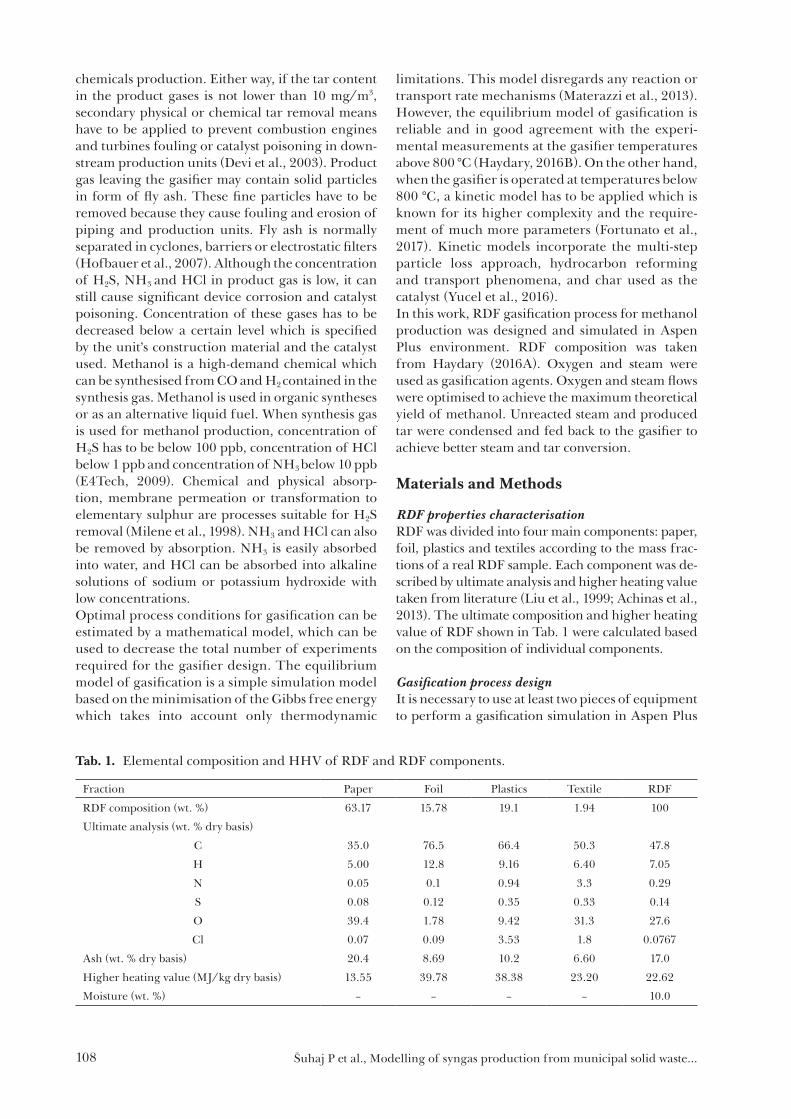
RDF properties characterisationRDF was divided into four main components: paper, foil, plastics and textiles according to the mass frac-tions of a real RDF sample. Each component was de-scribed by ultimate analysis and higher heating value taken from literature (Liu et al., 1999; Achinas et al., 2013). The ultimate composition and higher heating value of RDF shown in Tab. 1 were calculated based on the composition of individual components.
Gasification process designIt is necessary to use at least two pieces of equipment to perform a gasification simulation in Aspen Plus
Tab. 1. Elemental composition and HHV of RDF and RDF components.
Fraction Paper Foil Plastics Textile RDF
RDF composition (wt. %) 63.17 15.78 19.1 1.94 100
Ultimate analysis (wt. % dry basis)
C 35.0 76.5 66.4 50.3 47.8
H 5.00 12.8 9.16 6.40 7.05
N 0.05 0.1 0.94 3.3 0.29
S 0.08 0.12 0.35 0.33 0.14
O 39.4 1.78 9.42 31.3 27.6
Cl 0.07 0.09 3.53 1.8 0.0767
Ash (wt. % dry basis) 20.4 8.69 10.2 6.60 17.0
Higher heating value (MJ/kg dry basis) 13.55 39.78 38.38 23.20 22.62
Moisture (wt. %) – – – – 10.0
Šuhaj P et al., Modelling of syngas production from municipal solid waste…

109
considering gas equilibrium: RYield reactor and RGibbs reactor. The RYield reactor is necessary for the transformation of solid components to a stream of elements based on the ultimate analysis, moisture and ash content. The RGibbs reactor is required for the calculation of equilibrium composition of gas containing CO, H2, CO2, H2O, CH4, N2, H2S, NH3 and HCl, which are composed of elements C, H, N, O, S and Cl. Tar yield can be calculated using a correlation and the Aspen calculator tool.
Gasification process conditions:Pure oxygen and steam were used as gasifying agents. Steam presence ensured increased H2 yield and the use of pure oxygen led to low concentra-tions of N2, CH4 and tars in the product gas.Temperature of used steam was set to 300 °C and that of supply water, RDF and oxygen was set to 20 °C. Water leaving the gasifier in the product gas
was condensed and recycled back to the gasifier as steam.
Gasification model assumptions:— 100 % conversion of RDF to gases and ash,— only CO, H2, CO2, H2O, CH4, NH3, HCl, H2S
and N2 are considered as gas components,— equilibrium gas composition in the gasifier,— naphthalene as model component for tars,— tars yield was calculated as a function of tem-
perature inside the gasifier,— no heat losses from the gasifier and heat ex-
changers,— atmospheric pressure inside the gasifier.
Gasification process scheme description:The gasifier model consisted of three reactors, three mixers, four splitters and four heat exchangers. The gasification process flow diagram is shown in
Fig. 1. Gasification process flow diagram.
Tab. 2. List of equipment.
Equipment name Block type Description
ASHSPLIT SSplit Removing ash from gasifier
HE1 HeatX Steam production from condensate
HE2 HeatX Steam production from supply water
HE3 HeatX High pressure steam generation from supply water
HE4 HeatX Condensing water and tars
MIX-1 Mixer Mixing of decomposed tars with recycled steam
MIX-2 Mixer Mixing of generated steam from supply water with supply steam
MIX-3 Mixer Mixing of recycled stream with pure oxygen
R-DECOMP1 RYield RDF decomposition
R-DECOMP2 RYield Tars decomposition
R-GASIFIER RGibbs Gas equilibrium composition calculation
SPLIT-1 Sep Tars separation from recycled stream
SPLIT-2 Sep Separation of supply steam
VL-SEP Flash2 Separation of condensate from product gas
Šuhaj P et al., Modelling of syngas production from municipal solid waste…

110
Fig. 1. RDF was defined as a solid component with known properties presented in Tab. 1. RDF was fed into the gasifier. The product gas leaving gasifier was cooled down in four heat exchangers to 30 °C. Water and tar in product gas condensed and were separated from gas. Condensate of water and tar was heated up to 300 °C by the product gas leaving the gasifier. The heated stream was returned back to the gasifier. Additional steam was fed to the gasifier. Additional steam was also generated by the product gas heat. A list and an explanation of all streams and equipment are provided in Tabs. 2 and 3.
Results and discussion
Four operating regimes were simulated and com-pared to evaluate the steam recycle efficiency:— gasification with oxygen,— gasification with oxygen and supply steam, with-
out steam recycle,— gasification with oxygen and steam recycle, with-
out supply steam,
— gasification with oxygen, steam recycle and sup-ply steam.
Efficiency of the gasification process was deter-mined by the methanol to RDF mass ratio calculated according to the following equations.
28. H
RDF
mMRR
ma=
(1)
2
7.CO
COH
mk
m=
(2)
if kCO 1; = 1 (3)
if kCO < 1; = kCO (4)
MRR is the methanol to RDF mass ratio determining the amount of methanol which can be synthesised from RDF when all H2 reacts with CO to methanol (or all CO if its content is insufficient). Product gas composition leaving VL-SEP (material stream P-GAS) was used for the calculation, especially the mass flow of H2, 2Hm , and CO, COm . kCO denotes the
Tab. 3. List of material streams.Material stream Description
ASH Ash from gasifier
OXYGEN Pure oxygen
P-GAS Product gas separated in VL-SEP
P-LIQUID1 Condensate of water and tars separated in VL-SEP
R-GAS1 Gas leaving R-GASIFIER
R-GAS2 Gas leaving ASHSPLIT
R-GAS3 Gas cooled in HE1
R-GAS4 Gas cooled in HE2
R-GAS5 Gas cooled in HE3
R-LIGAS1 Gas-liquid mixture leaving HE4
R-RDF Decomposed RDF
R-STEAM Heated and evaporated recycled stream
R-TARS1 Separated tars from R-STEAM1
R-TARS2 Decomposed tars
S-STEAM Steam separated from the mixture of steam and tars
STEAM1 Steam generated from supply water
STEAM2 Mixture of generated steam from supply water with supply steam
STEAM3 Steam generated from supply water after supply steam separation
STREAM1 Decomposed tars, steam and soluble gases – recycled stream
STREAM2 Decomposed tars, oxygen, steam and soluble gases
S-STEAM2 Steam generated from cooling water
S-WATER1 Supply water for steam generation used as gasifying agent
S-WATER2 Cooling water for steam generation not consumed as gasifying agent
S-WATER3 Cooling water
S-WATER4 Heated cooling water
X-STEAM1 Supply steam for calculation purposes
X-STEAM2 Supply steam for calculation purposes
Šuhaj P et al., Modelling of syngas production from municipal solid waste…

111
excess of CO, if its value is above 1, variable is equal to 1 because H2 is the limiting reagent. If its value is below 1, variable is equal to kCO and CO is the limiting reagent.Optimal oxygen to RDF mass ratio and steam to RDF mass ratio were estimated for every operating regime to reach the highest MRR value. Tem-perature in the gasifier varied between 900 °C and 1000 °C, which was set as another condition. High temperature in the gasifier ensured methane and tar decomposition.
Gasification with oxygenIn this case, only pure oxygen was used as the gasify-ing agent. The product gas was cooled down and the condensate was separated. MRR and temperature are shown in Fig. 2 as a dependence of the oxygen to RDF mass ratio; it can be seen that both curves have a local maximum. The temperature increased very slowly when MRR reached the maximum. After MRR reached the maximum, the temperature started increasing sharply due to H2 and CO oxidation. At high oxygen to RDF mass ratio, the temperature does not increase because of the CO2 and H2O decompo-sition to H2, CO and O2 as the equilibrium is shifted to H2 and CO products. The oxygen consumption for 100 % RDF conversion was 0.341 kg O2 per kg of RDF according to the simulation.The maximum MRR value was 0.5128 and it was reached at the oxygen to RDF mass ratio of 0.3624. The temperature was only 805.9 °C under these conditions; therefore, the oxygen to RDF mass ratio had to be higher. Optimal oxygen to RDF mass ratio was 0.3840; then, MRR was 0.5012 and the gasifier temperature was 900.7 °C.
Gasification with oxygen and supply steam without steam recycleIn this case, oxygen and supply steam were used as gasifying agents. No recycle of the unreacted steam
and tar was considered but the condensate was separated from the product gas.Fig. 3 shows MRR dependence on the oxygen to RDF mass ratio and the steam to RDF mass ratio. Maximum MRR was 0.6404 and it was reached at the oxygen to RDF mass ratio of 0.3660 and the steam to RDF mass ratio of 0.3900. However, the gasifier temperature was only 769.8 °C. Compared to the previous case, the oxygen to RDF mass ratios have a similar value but the use of steam led to an MRR in-crease and a temperature decrease. Thus, to achieve the gasifier temperature of at least 900 °C, higher oxygen to RDF mass ratio was required. The optimal oxygen to RDF mass ratio was 0.4050 and the steam to RDF mass ratio was the same, the temperature reached was 902.5 °C and MRR was 0.5883.
Gasification with oxygen and steam recycle without supply steamHere, oxygen and recycled steam were used as gasi-fying agents, thus, the steam to RDF mass ratio was depended on the water content in the gas leaving the gasifier. MRR and temperature are shown in Fig. 4 as a dependence on the oxygen to RDF mass ratio. It can be seen that both curves have a local maximum and the MRR maximum is located above the temperature of 1 000 °C. The temperature was lower compared to the first case; however, high oxy-gen to RDF mass ratio led to high water production, which was recycled as steam and caused a decrease in temperature as shows Fig. 5.Therefore, temperature was limited to 1 000 °C and thus the optimal oxygen to RDF mass ratio was 0.4392, MRR was 0.5613, steam to RDF mass ratio was 0.4189 and temperature in the gasifier was 1000.5 °C. There was a small difference between the MRR values at the temperature of 900 °C; the oxygen to RDF mass ratio was 0.3984, MRR was 0.5562, steam to RDF mass ratio was 0.1862 and temperature was 901.6 °C.
Fig. 2. Methanol to RDF mass ratio and gasifier temperature.
Šuhaj P et al., Modelling of syngas production from municipal solid waste…

112
Fig. 3. Methanol to RDF mass ratio versus the oxygen to RDF mass ratio and the steam to RDF mass ratio.
Fig. 4. Methanol to RDF mass ratio and temperature versus the oxygen to RDF mass ratio.
Fig. 5. Methanol to RDF mass ratio and steam to RDF mass ratio dependence on the oxygen to RDF mass ratio.
Šuhaj P et al., Modelling of syngas production from municipal solid waste…

113
Gasification with oxygen, steam recycle and supply steamIn this last case, the gasification process was set as described in Materials and Methods. Fig. 6 shows results of the simulation. Maximum MRR in this case was 0.6760 at the oxygen to RDF mass ratio of 0.3900, steam to RDF mass ratio of 0.6000 and the temperature of 798.3 °C. The amount of recycled steam was not sufficient to maintain the steam to RDF mass ratio; the supply steam to RDF mass ratio was 0.1332. The optimal oxygen to RDF mass ratio was 0.4230 and the steam to RDF mass ratio was 0.6060. Under these conditions, MRR of 0.6285, temperature of 900.5 °C and the supply steam to RDF mass ratio of 0.07263 were observed.Results of all simulations are summarised in Tab. 4. Recycled steam has shown better effect than the supply steam as it also contains tars. The use of steam led to lower gasifier temperature in all cases,
the highest MRR values were reached below the temperature of 900 °C.
Conclusion
Refuse-derived fuel gasification simulation in the Aspen Plus environment was performed using an equilibrium reactor model. The gasification pro cess simulation results showed in all cases that using recycled steam and supply steam with oxygen as gasifying agents (fourth case) led to higher MRR. When only oxygen was used as the gasifying agent, MRR was only 0.5012, but when recycled steam and supply steam were used, MRR was 0.6285, which is about 25 % higher compared to the first case when the temperature of 900 °C was reached. In other cases, MRR was higher than in the first case. When only oxygen and supply steam were used as gasify-ing agents, MRR was 0.5883. In case of recycled
Fig. 6. Methanol to RDF mass ratio versus the oxygen to RDF mass ratio and the steam to RDF mass ratio.
Tab. 4. Gasification results.
Oxygen to RDF
Mass Ratio
Recycled Steam
to RDF Mass
Ratio
Supply Steam
to RDF Mass
Ratio
Steam to RDF
Mass Ratio
Temperature
(°C)MRR
Case 1 0.3624 805.9 0.5128
0.3840 900.7 0.5012
Case 2 0.3660 0.3900 0.3900 769.8 0.6404
0.4050 0.3900 0.3900 902.5 0.5883
Case 3 0.4392 0.4189 0.4189 1000.5 0.5613
0.3984 0.1862 0.1862 901.6 0.5562
Case 4 0.3900 0.4668 0.1332 0.6000 798.3 0.6760
0.4230 0.5334 0.07263 0.6060 900.5 0.6285
Šuhaj P et al., Modelling of syngas production from municipal solid waste…

114
steam and oxygen used as gasifying agents, MRR was 0.5562.Future research in RDF gasification modelling can be focused on the gasifier temperature increase. Higher steam temperature should be applied. Temperature and heat value of product gas allow generating steam with temperature of above 300 °C. Increasing the temperature by steam instead of further addition of O2 should lead to CO2 and H2O decomposition and increased CO and H2 produc-tion. Also, the decrease of RDF moisture should lead to gasifier temperature increase.
AcknowledgementThis work was supported by the Grant APVV-15-0148 pro-vided by the Slovak Research and Development Agency.
List of symbolsHHV Higher heating value MJ/kgkCO Excess of carbon monoxide LHV Lower heating value MJ/Nm3
COm Carbon monoxide mass flow kg/hMEOH Methanol
2Hm Hydrogen mass flow kg/h
RDFm RDF mass flow kg/hMRR Methanol to RDF Mass Ratio MSW Municipal solid waste RDF Refuse-derived fuel
Greek symbols
Variable for carbon monoxide excess
References
Achinas S, Kapetanios E (2013) Energy and Environment Research, Vol. 3, No. 1: 150—157.
Devi L, Ptasinski KJ, Janssen FJ (2003) Biomass and Bioenergy 24: 125—140.
E4Tech (2009) Review of Technologies for Gasification of Biomass and Wastes, final report.
Fortunato B, Brunetti G, Campporeale SM, Torresi M, Fornaretti F (2017) Energy Conversion and Managemet 140: 281—294.
Haydary J (2016A) GeoScience Engineering 62: 37—44.Haydary J (2016B) Proceedings of the 4th International
Conference on Sustainable Solid Waste Management, Limassol, Cyprus University of Technology, Cyprus.
Hofbauer H, Rauch R, Ripfel-Nitsche K (2007) Gas cleaning for synthesis applications, Work package 2E, Vienna, University of Technology, Austria.
Liu DHF, Lipták BG (1999) Hazardous Waste and Solid Waste. CRC Press LLC, Boca Raton, FL.
Materazzi M, Lettieri P, Mazzei L, Taylor R, Chapman C (2013) Fuel 108: 356—369.
Milene TA, Evans RJ (1998) Biomas Gasifier Tars: Their Nature, Formation, and Conversion, National Renewable Energy Laboratory, Colorado, USA.
Shahbaz M, Yusup S, Inayat A, Onoja D, Onoja P, Ammar M (2017) Renewable and Sustainable Energy Reviews 73: 468—476.
Yucel O, Hastaoglu MA (2016) Fuel Processing Technology 144: 145—154.
Zhao L, Giannis A, Lam WY, Lin SX, Yin K, Yuan GA, Wang JY (2016) Sustainable Environment Research 26: 51—54.
Zhou H, Meng A, Long Y, Li Q, Zhang Y (2014) Renewable and Sustainable Energy Reviews 36: 107—122.
Šuhaj P et al., Modelling of syngas production from municipal solid waste…