modelling the application of adaptive optics to wide-field
TRANSCRIPT

Journal of Microscopy, Vol. 226, Pt 1 April 2007, pp. 33–42
Received 28 July 2006; accepted 04 December 2006
Modelling the application of adaptive optics to wide-fieldmicroscope live imaging
Z V I K A M ∗, P E T E R K N E R†, DAV I D AG A R D†,‡A N D J O H N W. S E DAT†∗
Weizmann Institute of Science, Rehovot 76100, Israel
†Department of Biochemistry and Biophysics, University of California at San Francisco, 600 16Street, San Francisco, CA 94158, W.M. Keck Advanced Microscopy Laboratory, U.S.A.
‡Howard Hughes Medical Institute, University of California San Francisco, San Francisco, CA94143, U.S.A.
Key words. Adaptive optics, live imaging aberrations, Microscopy.
Summary
Wide-field fluorescence microscopy is an essential tool inmodern cell biology. Unfortunately the image quality offluorescence microscopes is often significantly degraded dueto aberrations that occur under normal imaging conditions.In this article, we examine the use of adaptive optics technologyto dynamically correct these problems to achieve close toideal diffraction limited performance. Simultaneously, thistechnology also allows ultra-rapid focusing without having tomove either the stage or the objective lens. We perform opticalsimulations to demonstrate the degree of correction that canbe achieved.
Introduction
Fluorescent light microscopy of live cells offers cell biologiststhe opportunity to study molecular and cellular mechanismsin action. Genetic tagging of proteins, especially rare ones,requires imaging with the best three-dimensional resolutionusing the highest possible numerical aperture objectives,efficient photon collection, minimal photo-damage, sufficientworking distances for thick samples, and minimal sampleperturbation during fast live data collection. In practice, allof these requirements cannot be met, and cell biologists mustcompromise on these aspects of fluorescence imaging. We testthe incorporation of adaptive optics to come much closer toachieving all of these objectives.
Fluorescence wide-field microscopy provides the optimalmethodology for harvesting the most photons in a given opticalconfiguration. Photon efficiency is of critical importance for invivo imaging and requires high numerical aperture objectives,
Correspondence to: Zvi Kam. Email: [email protected].
which use an immersion medium, such as oil, glycerol orwater. However, the index of refraction of living tissue isdifferent than any of these immersion media. Therefore,imaging into live samples degrades the resolution, contrastand peak intensity of the image very rapidly with depth(Hiraoka et al., 1990; Gibson & Lanni, 1991; Kam et al., 1997;Kam et al., 2001; Hanser et al., 2002). This degradation iscaused by depth-dependent aberrations (most significantly,spherical aberrations). Aberrations significantly degradethe performance of deconvolution algorithms routinelyapplied for three-dimensional wide-field image reconstructionwith high NA objectives (Swedlow et al., 2002). Usingdeconvolution algorithms the signal-to-noise ratio andresolution, particularly in the axial direction, are enhancedby pushing the out-of-focus light back to its true three-dimensional source (Swedlow et al., 1997; Swedlow & Platani,2002; Swedlow, 2003). Aberrations make it impossible tofaithfully reconstruct the source of the out-of-focus light. Thedepth aberration problem is fundamental for laser scanningmicroscopes as well, particularly two-photon microscopy,causing loss of signal intensity (Marsh et al., 2003; Tsai et al.,2005) and for laser tweezers applications, causing loss ofbeam holding forces (Theofanidou et al., 2004). Finally, thepresence of spherical aberrations inhibits the application ofstructured illumination techniques which otherwise have theability to double the three-dimensional optical resolution inlight microscopy (Gustafsson, 2000; Gustafsson et al., 2005).
The image of a point source, known as the pointspread function (PSF), provides an effective means tocharacterize aberration-induced image distortions. Depth-dependent aberrations scale roughly as the difference inthe refractive indices of the immersion medium (n) and thesample (n′) multiplied by the depth within the sample (seeEq. 2 and its Taylor expansion for small (n′–n) below). Thus
C© 2007 The AuthorsJournal compilation C© 2007 The Royal Microscopical Society
3 4 Z . K A M E T A L .
with an immersion oil of refractive index, n = 1.518, apoint image 50 μm below the coverslide in glycerol (n =1.4746, refractive index difference, �n = 0.0434) has similardistortions as a point image 12 μm inside a volume of a typicalbuffer (n = 1.341, �n = 0.177). The corresponding peakintensity is about four times lower than would be detectedfor an identical point source right under the coverslide.For a water immersion objective imaging into tissue (n =1.41, �n = 0.077), comparable distortions will appear at28 μm depth. Aberrations can be corrected by adjusting therefractive index of the immersion medium (Hiraoka et al.,1990) by adjusting special collars on objectives, or by insertingadditional adjustable optics into the microscope imaging tube(Kam et al., 1997).
More generally, spherical and other aberrations can beunderstood to arise from differences in optical path at differentlocations in the optical wavefront (Ross, 1954). Given apoint source imaged at different focal planes, it is possibleto reconstruct wavefront amplitude and phase variations inthe back aperture of the objective lens. This can then beused in a mixed Fourier/real-space deconvolution algorithm tocomputationally correct for depth-dependent changes in thePSF (Hanser, 2003). The more general case of sample-inducedaberrations was addressed in another paper (Kam et al., 2001)using space-variant deconvolution computed from ray-tracedPSFs. Aberrations can thus be corrected by modifying optics(Hiraoka et al., 1990; Kam et al., 1997) or by computationalapproaches (Kam et al., 2001; Hanser et al., 2002). Inevitably,these approaches slow down the image acquisition process andpose a serious computational burden for the reconstruction.However, an alternative approach would be to directly correctimage distortions by introducing compensating optical pathdifferences into the optical wavefront. The development of fastadaptive optics (AO) elements which can adjust the opticalpath length over the aperture opens new possibilities for real-time correction of both depth-dependent and sample-inducedaberrations in live sample microscopy. Moreover, AO elementscan alter the optical wavefront so that the focal plane is sweptthroughout the sample without having to move either theobjective lens or the stage.
AO has had an extraordinary impact in astronomy (Tyson,1991; Wizinowich & Bonaccini, 2002) and has recently beenapplied to medical imaging and confocal microscopy (Albertet al., 2000; Bartsch et al., 2002; Booth et al., 2002; Shirai,2002; Schwertner et al., 2004). The correction of aberrationsin astronomy (and a recent implementation in scanningconfocal microscopy) relies on evaluation of the distortion ofpoint sources (bright stars or the confocal exciting beam) andsubsequent modification of the AO element to correct for thesedistortions. The AO approach described here, in contrast to theastronomy paradigm, deals with the case when we can defineand characterize the aberrations beforehand. This approachallows for faster correction and minimizes bleaching becauseextra images do not need to be acquired. Here we consider
two different modes of applying AO to light microscopy oflive samples. In the first mode we insert the AO element ina pupil conjugate plane, allowing dynamic focusing withoutsample perturbation while correcting spherical aberrationon the fly for each depth. In the following simulations, weconsider imaging into a water-based sample with an oil-immersion lens to demonstrate the correction possible in theextreme case. Through the use of multiple AO elements, thesecond mode additionally makes possible correction of localrefractive index variations within the sample. In this case, wewould utilize Differential Interference Contrast (DIC) imagingto empirically provide the required three-dimensional map ofindex of refraction variations within the sample (Kam 1998;Kam et al., 2001).
Methods
The ray tracing program, described in detail before (Kamet al., 2001), is based on the analytical solution of ray pathsand phases in a gradient refractive index medium. With thisalgorithm a larger integration step can be used for a givenaccuracy than in the common method of Sharma et al. (1982),therefore cutting the processing time. A fan of homogeneouslyspread rays within a given aperture cone is generated, tracedthrough a refractive index medium, mapped onto a three-dimensional grid, and the emerging wavefront phases atinfinity are used to evaluate the Strehl ratio as a complexamplitude integral over the wavefront (Hardy, 1998). In thiswork a fluctuating refractive index medium was simulated byadding three-dimensional Gaussians at random displacementsfrom a three-dimensional grid according to:
n(r ) = n0 + �n∑
G (r − rn), (1)
where G(r) = exp(–|r/w|2), r = (x, y, z), rn = (i + pi)1x + (j +pj)1y + (k + pk)1z, i, j, k are integers, pipjpk are uniform randomvariables between 0 and 1 and 1x1y1z are vectors along xyzspanning a three-dimensional grid with spacing proportionalto w, the Gaussian width. Various dimensions and refractiveindex contrasts were generated and ray traced. The reportedresults here correspond to about 500 Gaussians at averagespacing of 3w. To calculate the effects of adaptive opticalelements, the rays emerging from the medium are ‘relayed’by ideal lenses as described in Figures 2 and 4, and treated byone or several adaptive optical devices by tracing to their planesand shifting the phases according to the position they hit.
The presentation of a finite slice of the medium by a singleconjugated adaptive optical plane followed one of severaloptions: Parallel-sum means integrating the optical path of theslice along the optical axis Z (and perpendicular to the plane) asa function of position XY. Fan-sum performs the optical pathintegration along rays emerging from the origin. For numericalapertures greater than 1.2, light rays inside the sample travelat angles greater than 45◦ with the optical axis. Thus thereis a significant difference between the parallel-sum and the
C© 2007 The AuthorsJournal compilation C© 2007 The Royal Microscopical Society, Journal of Microscopy, 226, 33–42

M O D E L L I N G A DA P T I V E O P T I C S M I C RO S C O P Y 3 5
Fan-sum methods when using a small number of conjugates.The Tokovinin option (see Tokovinin et al., 2000) ‘blurs’ eachslice by an amount increasing with distance from the conjugateplane, and in proportionality to the field of view.
The Zemax ray tracing program (Bellevue, WA 98004-8017) was applied to the Nikon objective described inYamaguchi (2003). The adaptive element was approximatedby expanding Eq. (3) in terms of the first five radial Zernikecoefficients.
Results
Correction of depth aberration for water-immersed samplesimaged with oil-immersion objectives
The three-dimensional image of a point source, the PSF, can bederived theoretically as a function of depth. The shift in opticalpath, �OP, from a source in a depth D of sample medium withrefractive index n ′ can be analytically expressed (Booth et al.,1998) as:
�OP = D (n′ cos θ ′ − n cos θ ) ∼ D (n′ − n)/ cos θ, (2)
whereθ′is the angle in the sample medium, andθ is the angle in
the immersion liquid with refractive index n, (see Fig. 1). Fromthe relation between ray angle and position in the back pupilplane, the PSF can be calculated as the Fourier transform ofthe back pupil plane wavefront. Theoretical calculations agreewith experimental measurements of the PSF shape (Gibson &Lanni, 1991; Booth et al., 1998). Since the phase shift dependson depth and ray angle alone, it can be corrected at eachfocal plane (depth) for the entire imaged field by introducing aphase correction for each ray at the back pupil plane, where itsposition corresponds to angle of emergence from the sample.
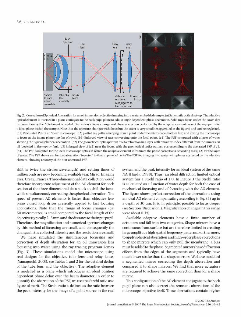
In Figure 2a we show a schematic microscope consistingof only the significant optical elements (an infinity correctedobjective and tube lens) with an AO element inserted in aplane conjugate to the back pupil plane using appropriaterelay optics. In all likelihood the implementation of the AOwould be accomplished by a deformable mirror, whose shapecan be changed dynamically, thus shifting the phase oflight in a controllable, position dependent manner. Usingcomputerizedraytracing,thestandardtechniquefordesigning
and evaluating optical systems, we can simulate both the effectof aberrations and the benefits of using a deformable mirror.The simulations for the extreme case of an oil immersionobjectiveimagingintowater(Fig.2bandc)showthataberratedPSFs computed for a series of depths can be effectively correctedby adjusting the phase for each ray according to its angleusing Eq. (2). Spherical aberration can therefore be perfectlycorrected by AO. Some aspects of the AO elements should beemphasized. The optical path adjustment needed for typicalbiological applications would require correction of about 2micrometres for every 10 micrometres of depth (substitutingin Eq. 2 n = 1.518 (oil) or n = 1.333 (water) and n
′ =1.43 (cytoplasm) with 65◦ rays). The number of elements(resolution) in the AO can be small since the correction curveversus angle is smooth and easy to fit by the adaptive mirrorslowest modes of surface displacement.
Fast dynamic focusing without sample perturbation
One goal in developing microscopes for in vivo imaging, isto maximize the rate of collecting three-dimensional imagestacks. A new imaging platform developed at UCSF (OMX)can acquire four-dimensional multiwavelength data at ratesof more than 10 three-dimensional images a second. A keyproblem when doing such fast sweeping of the focus is howto avoid distortion of the cover slide and the sample byforces transmitted through the immersion liquid in responseto the objective lens motion. Simulations demonstrate thatit is possible to add a global curvature term to the AOsurface thus shifting the focus with no movement of eitherthe objective or the stage (see Fig. 2a, dashed rays). Sinceshifting the image plane from the optimally corrected focalplane is associated with increasing aberrations, the respectiveaberration correction terms must also be added to the surfaceshape of the AO element. The path length change forsimultaneous focussing and correction is (see Fig. 1):
�OP = D n′ cos θ ′. (3)
Sufficient stroke (maximal axial movement) of the AO willyield a focus shift in the sample space that can cover thethickness of typical biological samples. AO mirrors with astroke of ±50 micrometre in their lowest mode (mirror phase
θ'
θD
sample immersion oil
n' n
Equation 2
θ'
θD
sample immersion oil
n' n
Equation 3
ba
Fig. 1. Calculation of phase aberration for sampledepth as a function of angle,θ . (a) Phase correction forimage at depth D. (b) Phase and focusing correctionfrom slide surface into depth D. The phase differenceis evaluated from the difference in length between thesolid and dashed lines measured from the source tothe dotted line representing a plane wavefront.
C© 2007 The AuthorsJournal compilation C© 2007 The Royal Microscopical Society, Journal of Microscopy, 226, 33–42
3 6 Z . K A M E T A L .
Fig. 2. Correction of Spherical Aberration for an oil immersion objective imaging into a water embedded sample. (a) Schematic optical set-up. The adaptiveoptical element is inserted in a plane conjugate to the back pupil plane to adjust angle dependent phase aberration. Solid rays: focus under the cover slip;no correction by the AO element is needed. Dashed rays: focus change and phase correction performed by the adaptive element correct the rays paths fora focal plane within the sample. Note that the aperture changes with focus but the effect is very small (exaggerated in the figure) and can be neglected.(b1) Calculated PSF of an ‘ideal’ microscope. (b2) plotted ray paths emerging from a point under the microscope (bottom fan) and exiting the microscopeto focus at the image plane (top fan of rays). (b3) Enlarged view of rays converging onto the focal point. (c1) The PSF computed with a layer of watershowing the typical spherical aberration. (c2) The geometrical optics pattern due to refraction in a layer with refractive index different from the immersionoil (depicted in the top ray fan). (c3) Enlarged view of (c2) near the focus, with the geometrical optics pattern corresponding to the aberrated PSF of c1.(b4) The PSF computed for the ideal microscope optics in which the adaptive element introduces the phase corrections according to Eq. (2) for the layerof water. The PSF shows a spherical aberration ‘inverted’ to that in panel c1. (c4) The PSF for imaging into water with phases corrected by the adaptiveelement, showing recovery of the non-aberrated PSF.
shift is twice the stroke/wavelength) and setting times ofmilliseconds are now becoming available (e.g. Mirao, Imagineeyes, Orsay, France). Three-dimensional data collection wouldtherefore incorporate adjustment of the AO element for eachsection of the three-dimensional data stack to shift the focuswhile simultaneously correcting the spherical aberration. Thespeed of present AO elements is faster than objective lenspiezo closed loop drives presently applied to fast focusingapplications. Note that the range of focus changes (ca.50 micrometres) is small compared to the focal length of theobjective(typically2–3mm)andthedistancetotheinputpupil.Therefore, the magnification and numerical aperture changesby this method of focussing are small, and consequently thechanges in the collected intensity and the resolution are small.
We have simulated the simultaneous focussing andcorrection of depth aberration for an oil immersion lensfocussing into water using the ray tracing program Zemax(Fig. 3). These simulations model the microscope usingreal designs for the objective, tube lens and relay lenses(Yamaguchi, 2003, see Tables 1 and 2 for the detailed designof the tube lens and the objective). The adaptive elementis modelled as a plane which introduces an ideal positiondependent phase delay over the beam diameter. In order toquantify the aberration of the PSF, we use the Strehl ratio as afigure of merit. The Strehl ratio is defined as the ratio betweenthe peak intensity for the image of a point source in the real
system and the peak intensity for an ideal system of the sameNA (Hardy, 1998). Thus, an ideal diffraction limited opticalsystem has a Strehl ratio of 1.0. In Figure 3 the Strehl ratiois calculated as a function of water depth for both the case ofmechanical focussing and of focussing with the AO element.The figure shows perfect correction of the aberrations usingan ideal AO element compensating according to Eq. (3) up toa depth of 30 um. It is, in principle, possible to focus deeper(see Section ‘Discussion’). Magnification changes in this rangewere about 0.1%.
Available adaptive elements have a finite number ofactuators and fall into two categories. Shape mirrors have acontinuous front surface but are therefore limited in creatinglarge amplitude high spatial frequency patterns. Furthermore,to apply spherical aberration and high-order phase correctionsto shape mirrors which can only pull the membrane, a biasmustbeaddedtothephase.Segmentedmirrorshavediffractioneffects from the edges of the segments and typically havemuch lower stroke than the shape mirrors. We have modelleda segmented mirror correcting the depth aberration andcompared it to shape mirrors. We find that more actuatorsare required to achieve the same correction than for a shapemirror.
This configuration of the AO element conjugate to the backpupil plane can also correct the remnant aberrations of themicroscope objective itself. These aberrations contain higher
C© 2007 The AuthorsJournal compilation C© 2007 The Royal Microscopical Society, Journal of Microscopy, 226, 33–42

M O D E L L I N G A DA P T I V E O P T I C S M I C RO S C O P Y 3 7
0
0.2
0.4
0.6
0.8
1
0 5 10 15 20 25 30
Depth (micrometers)
Str
eh
l R
ati
o
- AO focus and depth aberrations correction
- Mechanical focus, no depth cor.
Fig. 3. (a) Ray trace comparison of the Strehl ratio achievable when focussing into water with an oil immersion objective. Squares: Mechanical focussing,adjusting the position of the objective to focus on different planes within the sample. Diamonds: AO focussing, the objective position is kept fixed with thenominal focal plane at the bottom of the cover slip, and the AO element is used to both change the focal plane and correct for depth aberration. The Strehlratio for AO focussing degrades slightly with depth because the desired AO element surface is approximated in the Zemax program with a limited numberof Zernike terms rather than the exact equation.
spatial frequencies at the edge of the pupil but smaller phaseshifts than are required for focussing. For this application, high-density MEMS AO elements with small strokes could be used(Bifano et al., 2004).
Correction of space-variant sample-induced aberrations
The second configuration (called multiconjugate AO inastronomy, Ragazzoni et al., 2000) tests the possibilityof employing a small number of adaptive elements tocorrect for space-variant aberrations introduced by three-dimensional refractive index fluctuations within the sample.In imaging through live cells, the optical path transversesorganelles such as the nucleus and the mitochondria, eachwith a different refractive index (Ross, 1954; Kam et al.,2001). Three-dimensional Differential Interference Contrast(DIC/Nomarski) microscopy allows one to measure the index ofrefraction gradients. Then line integration, a rapid computingstep, can be used to produce a complete three-dimensionalmap of the sample refractive index (Van Munster et al., 1997;1998; Kam, 1998; Kam et al., 2001; Arnison et al., 2004;King & Cogswell, 2004). Line integration by itself requiresseveral milliseconds of computer time. Line integration withdeconvolution (LID) of a 512 × 512 DIC image requires 0.2 susing a 2.2 GHz Pentium 4 XEON computer. Optimization ofthe fast fourier transform code can shorten processing timeby a factor of 2–5. Since the processing is two-dimensional,simple parallelization using computer clusters will require 0.2 sor less also for three-dimensional stacks. The acquisition of aseries of DIC images, the calculation of the three-dimensionalrefractive index map and the setting of the adaptive elements
can thus all be performed very rapidly, therefore this approachis practical for real experimental conditions in live cell imaging.
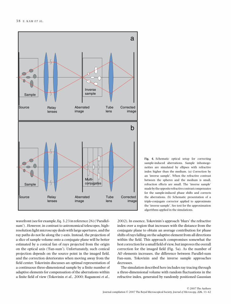
The mode of correction here requires a different approachfrom the correction of depth aberration, since the phase shiftsmeasured at the back aperture are position dependent (dependfor each wavefront on its point of origin within the samplevolume). The way to correct these space-variant aberrationsis to guide the wavefront through an ‘inverse sample’(Fig. 4a) that consists of the opposite refractive index contrastsof the sample. If refraction is negligibly small, an inversesample would perfectly correct the phase shifts which each rayaccumulates in traversing the sample. We show by simulationthat this hypothetical solution works very well for the refractiveindex variations within live cells (�n ∼ 0.06 between thecytoplasm and the nucleus, Ross, 1954). In practice, thethree-dimensional inverse of the sample refractive index canbe approximated by a sequence of adaptive elements beforethe image-forming plane, each compensating for the phaseshifts in a finite thickness range within the sample (Fig. 4b).This ‘multiconjugates’ approach in telescopes employs severaladaptive optical elements, each correcting aberrations due toatmospheric turbulences at the optically conjugated height.Typically, one height is right above the telescope, and othersare several kilometre above. The following analyzes possibleimplementations of this approach in microscopy.
A single AO element could correct the aberrations perfectlyat a single point. Multiple AO elements conjugated to multipleplanes in the sample are required in order to correct theaberrations over a finite field of view. To determine thecorrection applied by each AO element, the optical pathalong the z-axis can be summed for each position in the
C© 2007 The AuthorsJournal compilation C© 2007 The Royal Microscopical Society, Journal of Microscopy, 226, 33–42
3 8 Z . K A M E T A L .
Sample
Inversesample
Source Aberratedimage
Corrected image
a
Relaylenses
Tubelens
Sample
Source Aberratedimage
Corrected image
b
Relaylenses
Tubelens
Multi-conjugates
Fig. 4. Schematic optical setup for correctingsample-induced aberrations. Sample inhomoge-neities are simulated by ellipses with refractiveindex higher than the medium. (a) Correction byan ‘inverse sample’. When the refractive contrastbetween the spheres and the medium is small,refraction effects are small. The ‘inverse sample’madebytheoppositerefractivecontrastcompensatesfor the sample-induced phase shifts and correctsthe aberrations. (b) Schematic presentation of atriple-conjugate corrector applied to approximatethe ‘inverse sample’. See text for the approximationalgorithms applied in the simulations.
wavefront (see for example, Eq. 3.23 in reference 26) (‘Parallel-sum’) . However, in contrast to astronomical telescopes, high-resolution light microscopy deals with large apertures, and theray paths do not lie along the z-axis. Instead, the projection ofa slice of sample volume onto a conjugate plane will be betterestimated by a conical fan of rays projected from the originon the optical axis (‘Fan-sum’). Unfortunately, such conicalprojection depends on the source point in the imaged field,and the correction deteriorates when moving away from thefield center. Tokovinin discusses an optimal representation ofa continuous three-dimensional sample by a finite number ofadaptive elements for compensation of the aberrations withina finite field of view (Tokovinin et al., 2000; Ragazzoni et al.,
2002). In essence, Tokovinin’s approach ‘blurs’ the refractiveindex over a region that increases with the distance from theconjugate plane to obtain an average contribution for phaseshifts of rays falling on the adaptive element from all directionswithin the field. This approach compromises somewhat thebest correction for a small field of view, but improves the overallcorrection for the imaged field (Fig. 5a). As the number ofAO elements increases, the difference between Parallel-sumFan-sum, Tokovinin and the inverse sample approachesdecreases.
The simulation described here includes ray tracing througha three-dimensional volume with random fluctuations in therefractive index, generated by randomly positioned Gaussian
C© 2007 The AuthorsJournal compilation C© 2007 The Royal Microscopical Society, Journal of Microscopy, 226, 33–42

M O D E L L I N G A DA P T I V E O P T I C S M I C RO S C O P Y 3 9
0
0.2
0.4
0.6
0.8
1
0 0.1 0.2 0.3 0.4 0.5
Field Position (mm)
Str
eh
l R
ati
o
a
0
0.2
0.4
0.6
0.8
1
0 0.001 0.002 0.003 0.004 0.005 0.006
Refractive Index Differences
Str
eh
l R
ati
o
b
4-conjugates
2-conjugates
-Tokovinin
-Fan-summ
-Parallel-sum
-Tokovinin
-Fan-summ
-Parallel-sum
- uncorrected
-inverse-
medium
no refraction
-inverse-
medium
with refraction
- 2 conjugates
- 4 conjugates
Fig. 5. (a) Plot of Strehl ratio versus field position showing multiconjugate correction for sample-induced aberrations. Sample consists of 500 Gaussianspheres with refractive index differences �n = 0.003. Open squares, triangles and circles: two conjugates approximated by Parallel-sum, Tokovinin andFan-sum methods, respectively; Solid squares triangles and circles: four conjugates, Parallel-sum, Tokovinin and Fan-sum methods respectively. (b) Strehlratio as a function of refractive index contrast for an axial source and 500 randomly positioned Gaussian spheres. Filled circles: uncorrected. Filledsquares and triangles: after correction by ‘inverse medium’ when refraction is suppressed, and with refraction, respectively. Open circles: correction bytwo conjugates. Filled diamonds: correction by four conjugates.
spheres each having refractive index higher by �n abovethe background, and M adaptive devices each arranged tocompensate 1/M of the sample thickness. The ray tracingsimulations do not take scattering effects into account. Weagain use the Strehl ratio to quantify the correction over thefield of view due to sample-induced aberrations. It is calculatedin our simulations by integrating the complex amplitude ofthe normalized light field over the pupil plane and taking themagnitude squared (Hardy, 1998). The Strehl ratio is a usefulcharacterization of the PSF only for small aberrations, sincemore complex distortions of the point image take place withlarge aberrations (Kam et al., 2001). To use the Strehl ratio asa good figure of merit we restrict our simulations here to values
of �n that allow comparison of Strehl ratios above 0.1. Thissimulation allows us to change �n and the size scale becauselive cells consist of a wide distribution of sizes, shapes and�n.
We tested the correction of aberrations for distributions ofspheres by a three-dimensional inverse sample (Fig. 5b). Asexpected, the inverse sample corrects the aberrations perfectlyif refraction is negligible. By suppressing refraction in thesimulated ray tracing we indeed obtain a Strehl ratio of 1.0.Refraction causes rays to trace different paths in the realand inverse samples, and thus the phase correction will beimperfect if �n is large. With refraction, the inverse mediumcorrection maintained Strehl ratios >0.85 throughout the
C© 2007 The AuthorsJournal compilation C© 2007 The Royal Microscopical Society, Journal of Microscopy, 226, 33–42

4 0 Z . K A M E T A L .
field for�n=0.01whiletheuncorrectedStrehlratiowas<0.1.The inverse medium can thus be viewed as the best possiblecorrection, equivalent to a large number of multiconjugates.While there are schemes for writing a three-dimensionalrefractive index map into a polymer media, such approachesare not realistic for dynamic imaging in live microscopy. Wehave therefore to resort to methods that utilize only a fewconjugate planes. Fig. 5a compares the Strehl ratio for thesimulated fluctuating refractive index medium, as a functionof source distance from the optical axis, for six cases: correctionat either two or four conjugate planes using the Parallel-sum,Fan-sum, and Tokovinin’s corrections. The correction by fourconjugates using the Fan-sum method is best on-axis, butdegrades as the source moves off-axis. The Tokovinin methoddoes not correct as well on-axis but the level of correctionis maintained as the source moves off-axis. We also testedthe effect of ‘segmentation’ (or number of actuators) in theadaptive element. For spheres the Strehl ratio approached 1.0when the effective pixel size related back to the sample becamesmaller than ∼1/3 of the sphere diameter.
Several details are worth noting. An initial three-dimensional refractive index map is required before fluorescentdata is collected. This refractive index map could be updatedbefore every three-dimensional fluorescent data acquisition,or periodically when sample changes are slow and thefluorescence acquisition rate is very fast. Ideally one wouldwant very high resolution of the AO elements, approachingin principle the resolution of the image itself. Achieving goodcompensation, for nuclei (3–10 μm size), for example, mightbe possible using AO conjugates with 50 or more elements(actuators).
Discussion
Using ray tracing simulations we have tested twoconfigurations for including AO elements in high-resolutionlight microscopes to correct aberrations associated withimaging of live thick biological specimens. Using adaptiveoptics in wide-field microscopy makes possible the correctionof parallel data acquisition at different depths and thus is anoptimal strategy for collecting live dynamic image information.Because the entire frame is collected at once in wide-field,the response time of the adaptive elements can be muchslower compared to the microsecond rates needed for adaptiveoptics correctors in scanning confocal microscopes (Albertet al., 2000; Booth et al., 2002). We show that correctingfor spherical aberration caused by focussing into samplebuffer even for the extreme refractive index mismatch withan oil-immersion objective is straightforward, simple to apply,and yields the double benefit of also providing a mechanism tomake very rapid focus changes without perturbing the sample.Because the refractive index of live cells is on the average 1.43,and varies between different tissues, an oil immersion lensis actually the most appropriate to use with adaptive optics.
When corrected with AO, it also has the benefit of providingthe highest possible numerical aperture and hence the bestresolution and light gathering power. Furthermore, completecorrection of depth dependent aberrations allows rapid, spaceinvariant computational deconvolution methods to correctfor the remaining out-of-focus blurring.
With large stroke AO devices becoming available, it shouldbe possible to image through many cell layers (100 μm ormore) in intact tissues. For optimal imaging of such verythick tissues it will also be necessary to develop methods tocorrect for higher order aberrations, as well as for dealing withlight scattering. Two-photon microscopy, which gives goodperformance in highly scattering tissue, will greatly benefitfrom adaptive optics correction.
Once an AO element is employed to correct depth-dependent aberrations at the back aperture, it would alsobe possible to simultaneously correct for additional opticalaberrations such as remnant phase shifts and asymmetriesexisting even in the best-selected objectives. These phaseshifts increase dramatically towards the high, peripheralacceptance aperture of the objective, which amounts to highorder aberration terms (Juskaitis & Wilson, 1997; Beverageet al., 2002; Hanser et al., 2002). They show temperatureand “age” dependence, especially serious in heat-incubatedenvironmental chambers used for imaging live biologicalsamples. Such objective-dependent phase aberrations can bedetermined optically (Juskaitis & Wilson, 1997; Beverage et al.,2002) or computationally (Hanser et al., 2002) but theirin situ correction using adaptive elements will be fast andwill increase image resolution and contrast. It would be alsopossible to use the same adaptive optic element to correctfor the small residual wavelength dependent aberrations thatotherwise would degrade multiwavelength imaging. Finally,if AO elements were to become a standard feature in opticalmicroscopes, it might be possible to greatly simplify the designof the objective lenses (e.g. to get rid of correction collars andto reduce number of lenses required for chromatic correction)and to achieve better overall performance and longer workingdistances using the flexible dynamic characteristics of AOelements to relax the multiple constraints imposed in objectivedesign.
The second mode explored here, tackles the morechallenging problem of correcting the smaller, but morecomplex, spatially variant aberrations arising from the opticalproperties of the sample itself. In wide-field imaging, a perfectcorrection would require the construction of an inverse samplehaving all the resolution and depth of the real sample, butthe opposite change in index of refraction. A more practicalalternative is to use a small number of multiconjugate AOelements. To explore the feasibility of this approach, we havesimulated the effects of using two or four AO elements with avariety of methods for calculating how each should be set givena three-dimensional map of refractive index variation withinthe sample. These simulations indicate that useful corrections
C© 2007 The AuthorsJournal compilation C© 2007 The Royal Microscopical Society, Journal of Microscopy, 226, 33–42

M O D E L L I N G A DA P T I V E O P T I C S M I C RO S C O P Y 4 1
can be obtained using two multiconjugate elements, whileusing four yields excellent results.
The use of several reflecting adjustable mirrors may bepossible, but physically cumbersome, for applications inmicroscopy. Transmitting adaptive elements (such as liquidcrystal spatial phase modulators) capable of introducingposition dependent phase shifts through their aperture(Dayton et al., 2002; Lee et al., 2005) can make thismulticonjugate approach practical and effective. They havea sufficiently high pixel density for correction of sample-induced aberrations, and their setting speed, being in themillisecond range, is reasonable for wide-field microscopy.However, the present devices have high transmission losses,imposing a serious constraint for their use in tandem. Thuswith current devices, it is most reasonable to consider only thetwo multiconjugate correction scheme.
The introduction of adaptive optics into light microscopyoptimize high-resolution imaging under the less than idealconditions typical in biological applications, increase three-dimensional sharpness and contrast for thick specimens, andallow the detection of finer details and weaker molecularsignals inside live cells. As outlined in the introduction, thislast point is the critical issue in live cell imaging. An importantaim of this paper is the stimulation and the developmentof new adaptive optics hardware and software in wide-fieldmicroscopy.
Acknowledgements
We thank the members of the U.C. Santa Cruz Center foradaptive optics for instructive discussions, Roberto Ragazzoni(Astrophysical Observatory of Florence), the leading experton multiconjugate telescopes, for stimulating guidance inseveral instances, and Mats Gustafsson (U. C. San Francisco)for numerous illuminating remarks. ZK is the Israel PollakProfessor of Biophysics. This work was supported by NIHGrants GM25101 (JWS) and GM31627 (DAA).
References
Albert, O., Sherman, L., Mourou, G. & Norris, T.B. (2000) Smartmicroscope: an adaptive optics learning system for aberration correctionin multiphoton confocal microscopy. Optics Lett. 25, 52–54.
Arnison, M.R., Larkin, K.G., Sheppard, C.J.R., Smith, N.I. & Cogswell, C.J.(2004) Linear phase imaging using differential interference contrastmicroscopy. J. Microscopy 214, 7–12.
Bartsch, D.U., Zhu, L., Sun, P.C., Fainman, S. & Freeman, W.R. (2002).Retinal imaging with a low-cost micromachined membrane deformablemirror. J. Biomed. Opt. 7, 451–456.
Beverage, J.L., Shack, R.V. & Descour, M.R. (2002) Measurement of thethree-dimensional microscope point spread function using a Shack-Hartman wavefront sensor. J. Microscopy 205, 61–75.
Bifano, T., Bierden, P., Perreault, J. (2004) Micromachined deformablemirrors for dynamic wavefront control. SPIE 5553, 1–16.
Booth, M.J., Neil, M.A.A. & Wilson, T. (1998) Aberration correction forconfocal imaging in refractive-index-mismatched media. J. Microsc.192, 90–98.
Booth, M.J., Neil, M.A.A., Juskaitis, R. & Wilson, T. (2002) Adaptiveaberration correction in a confocal microscope. Proc. Natl. Acad. Sci.U.S.A. 99, 5788–5792.
Dayton, D., Gonglewski, J., Restaino, S., Martin, J., Phillips, J., Hartman, M.,Browne, S., Kervin, P. et al. (2002) Demonstration of new technologyMEMS and liquid crystal adaptive optics on bright astronomical objectsand satellites. Opt. Express 10, 1508–1519.
Gibson, S.F. & Lanni, F. (1991) Experimental test of an analytical model ofaberration in an oil-immersion objective lens used in three-dimensionallight microscopy. J. Opt. Soc. Am. A 8, 1601–1613.
Gustafsson, M.G.L. (2000) Surpassing the lateral resolution limit by afactor of two using structured illumination microscopy. J. Microscopy198, 82–87.
Gustafsson, M.G. (2005) Nonlinear structured-illumination microscopy:wide-field fluorescence imaging with theoretically unlimited resolution.Proc. Natnl. Acad. Sci. U.S.A. 102, 13081–13086.
Hanser, B.M. (2003) computational corrections for three-dimensionalwide field fluorescence microscopy. PhD Dissertation, University ofCalifornia at San Francisco.
Hanser, B.M., Gustafsson, M.G.L., Agard, D.A. & Sedat, J.W. (2002) Phaseretrieval for high-numerical-aperture optical systems. Opt. Lett. 28,801–803.
Hardy, J.W. (1998) Adaptive Optics for Astronomical Telescopes. OxfordUniversity Press, New York.
Hiraoka, Y., Sedat, J.W. & Agard, D. (1990) Determination of the three-dimensional imaging properties of a light microscope system. Biophys.J. 57, 325–333.
Juskaitis, R. & Wilson, T. (1997) Pupil function aberration can beaccurately described by phase function. J. Microscopy 189, 8–11.
Kam, Z. (1998). Microscopic differential interference contrast imageprocessing by line integration (LID) and deconvolution. BioImaging 6,166–176.
Kam, Z. Agard, D.A. & Sedat, J.W. (1997) Three-dimensional microscopyin thick biological samples: a fresh approach for adjusting focus andcorrecting spherical aberration. BioImaging 5, 40–49.
Kam, Z., Hanser, B., Gustafsson, M.G.L., Agard, D.A. & Sedat, J.W. (2001)Computational adaptive optics for live three-dimensional biologicalimaging. Proc. Natnl. Acad. Sci. U.S.A. 98, 3790–3795.
King, S.V. & Cogswell, C.J. (2004) A phase-shifting DIC technique formeasuring3Dphaseobjects:experimentalverification. Proc.SPIE5324,191–196.
Lee, J-H., Kim, D-W., Wu, Y-H., Yu, C-J., Lee, S-D. & Wu, S-T. (2005) High-speed infrared phase modulators using short helical pitch ferroelectricliquid crystals. Opt. Express 13, 7732–7740.
Marsh, P.N., Burns, D. & Girkin, J.M. (2003) Practical implementationof adaptive optics in multiphoton microscopy. Opt. Express 11, 1123–1130.
Ragazzoni, R., Diolaiti, E., Farinato, J., Fedrigo, E., Marchetti, E., Tordi, M. &Kirkman, D. (2002) Multiple field of view layer oriented adaptive optics.Astron. Astrophys. 396, 731–744.
Ragazzoni, R., Marchetti, E. & Vatente, G. (2000) Adaptive-opticscorrections available for the whole sky. Nature 403, 54–56.
Ross, K.F.A. (1954) The changes of water distribution in cytoplasm andnuclear sap during division as indicated by changes in their refractiveindices. J. Micrsc. Sci. 95, 425–432.
C© 2007 The AuthorsJournal compilation C© 2007 The Royal Microscopical Society, Journal of Microscopy, 226, 33–42

4 2 Z . K A M E T A L .
Schwertner, M., Booth, M.J. & Wilson, T. (2004) Characterizing specimeninduced aberrations for high NA adaptive optical microscopy. Opt.Express 12, 6540–6552.
Sharma, A., Kumar, D.V. & Ghatak, A.K. Tracining (1982) Rays throughgraded-index media – a new method. Appl. Opt. 21, 984–987.
Shirai, T. (2002) Liquid-crystal adaptive optics based on feedbackinterferometry for high-resolution retinal imaging. Appl Opt. 41, 4013–23.
Swedlow, J.R. & Platani, M. (2002) Live cell imaging using wide-fieldmicroscopy and deconvolution. Cell Struct. Funct. 27, 335–341.
Swedlow, J.R., (2003) Quantitative fluorescence microscopy and imagedeconvolution. Methods Cell Biol. 72, 349–367.
Swedlow, J.R., Hu, K., Andrews, P.D., Roos, D.S., & Murray, J.M. (2002)Measuring tubulin content in Toxoplasma gondii: a comparison oflaser-scanning confocal and wide-field fluorescence microscopy. Proc.Natl. Acad. Sci. U.S.A. 99, 2014–2019.
Swedlow, J.R., Sedat, J.W. & Agard, D.A. (1997) Deconvolution in opticalmicroscopy. Deconvolution of Images and Spectra, 2nd ed., (ed. by Jansson,P.A.), pp. 284–309. Academic Press, NY.
Theofanidou, E., Wilson, L., Hossack, W.J. & Arlt, J. (2004) Sphericalaberration correction for optical tweezers. Opt. Comm. 236, 145–150.
Tokovinin, A. Le Louarn, M. & Sarazin, M.(2000) Isoplanatism in amulticonjugate adaptive optics system. J. Opt. Soc. Am. A 17, 1819–1827.
Tsai, P.S., Kim, T.N., Campbell, K., Groisman, A., Kam, Z. & Kelinfeld, D.(2005) Spherical aberration correction in deep multi-photon imaging.OSA Annual Meeting, Focus in Optics, Tucson, AZ. October.
Tyson, K.K. (1991) Principles of Adaptive Optics. Academic,New York.
Van Munster, E.B., Van Vliet, L.J. & Aten, J.A. (1997) Reconstruction ofoptical pathlength distributions from images obtained by a wide-fielddifferential interference contrast microscope. J. Microscopy 188, 149–157.
Van Munster, E.B., Winter, E.K. & Aten, J.A. (1998) Measurement-based evaluation of optical pathlength distributions reconstructed fromsimulated differential interference contrast images. J. Microscopy 191,170–176.
Wizinowich, P.L. & Bonaccini, D. (Eds.) (2002) Adaptive opticalsystem technologies II. SPIE Proc. V 4839, 22–26 Aug. Waikoloa,Hawaii.
Yamaguchi, K. (2003) Immersion microscope objective lens. US PatentNo. 6,519,092 B2.
C© 2007 The AuthorsJournal compilation C© 2007 The Royal Microscopical Society, Journal of Microscopy, 226, 33–42