modelling the mechanical behaviour of typical wall-to
TRANSCRIPT
Contents lists available at ScienceDirect
Engineering Structures
journal homepage: www.elsevier.com/locate/engstruct
Modelling the mechanical behaviour of typical wall-to-floor connectionsystems for cross-laminated timber structures
Matteo Izzia,b,⁎, Andrea Polastria, Massimo Fragiacomoc,a
aNational Research Council of Italy – Trees and Timber Institute (CNR IVALSA), Via Biasi 75, 38010 San Michele all’Adige, ItalybDepartment of Engineering and Architecture, University of Trieste, Piazzale Europa 1, 34127 Trieste, Italyc Department of Civil, Construction-Architectural and Environmental Engineering, University of L’Aquila, Via Gronchi 18, 67100 L’Aquila, Italy
A R T I C L E I N F O
Keywords:Cross-laminated timberAnnular-ringed shank nailSteel-to-timber jointMetal connectorWall-to-floor connectionNon-linear modellingHysteretic behaviour
A B S T R A C T
This paper proposes a numerical model capable of predicting the mechanical behaviour and the failure me-chanism of typical wall-to-floor connections for Cross-Laminated Timber structures. Such systems are assembledwith angle brackets and hold-downs, anchored to the wall and floor panels with profiled nails and bolts. Themetal connector and the elements to which it is fastened are modelled using 3D solid bodies, while the steel-to-timber joints are simulated as non-linear hysteretic springs. Shear and tension tests are reproduced on twoconnection systems and results are compared to the test data obtained from similar configurations. Simulationslead to accurate predictions of the mechanical behaviour (i.e. elastic stiffness, maximum load-carrying capacity,and shape of the hysteresis cycles) and energy dissipation. Finally, the performance when lateral and axial loadsare applied simultaneously is investigated. Analyses are carried out by varying the inclination of the load, withrespect to the axis of the connector, between 0° and 90°. Results exhibit a quadratic interaction relationshipbetween shear and tension loads, and prove that their coupled effect influences the stiffness and the maximumload-carrying capacity.
1. Introduction
As a structural product, Cross-Laminated Timber (CLT) exhibits ahigh in-plane stiffness and a linear-elastic behaviour with tendency tofail with brittle mechanisms (except for compressive stresses).Therefore, mechanical connections between CLT walls and floor panelsrepresent the ductile zones of CLT structures, supplying the strength,stiffness, and energy dissipation under seismic conditions [1].
The mechanical behaviour of wall-to-floor connection systems forCLT structures has been the focus of several research projects. Shearand tension tests have been carried out on different types of anglebrackets and hold-downs, varying the geometry of the connectors andthe number of nails [2–6]. Recently, tests have been performed underthe simultaneous application of lateral and axial loads, highlightingthat the coupled shear-tension action affects the stiffness, the load-carrying capacity and the energy dissipation [7,8].
The increasing use of CLT for the construction of mid- and high-risestructures (the so-called ‘tall buildings’) requires connections with ex-cellent mechanical properties and large ductility ratios. However, theoutcomes of past test programmes highlighted some inappropriatefailure mechanisms that might limit the application of the metal
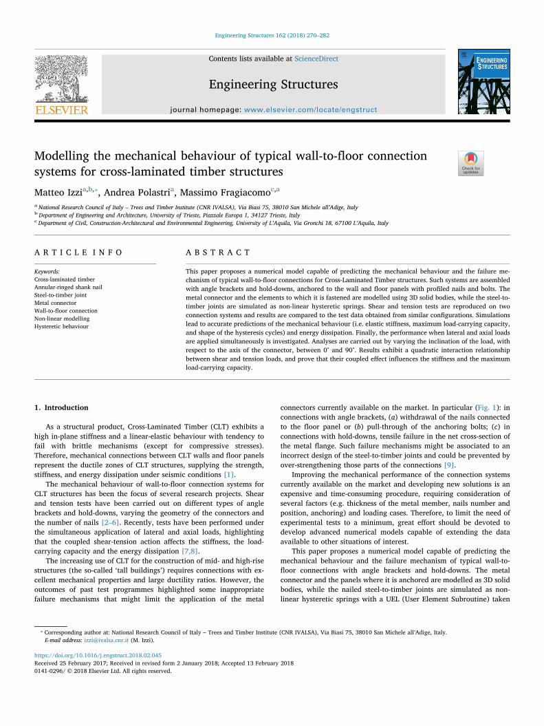
connectors currently available on the market. In particular (Fig. 1): inconnections with angle brackets, (a) withdrawal of the nails connectedto the floor panel or (b) pull-through of the anchoring bolts; (c) inconnections with hold-downs, tensile failure in the net cross-section ofthe metal flange. Such failure mechanisms might be associated to anincorrect design of the steel-to-timber joints and could be prevented byover-strengthening those parts of the connections [9].
Improving the mechanical performance of the connection systemscurrently available on the market and developing new solutions is anexpensive and time-consuming procedure, requiring consideration ofseveral factors (e.g. thickness of the metal member, nails number andposition, anchoring) and loading cases. Therefore, to limit the need ofexperimental tests to a minimum, great effort should be devoted todevelop advanced numerical models capable of extending the dataavailable to other situations of interest.
This paper proposes a numerical model capable of predicting themechanical behaviour and the failure mechanism of typical wall-to-floor connections with angle brackets and hold-downs. The metalconnector and the panels where it is anchored are modelled as 3D solidbodies, while the nailed steel-to-timber joints are simulated as non-linear hysteretic springs with a UEL (User Element Subroutine) taken
https://doi.org/10.1016/j.engstruct.2018.02.045Received 25 February 2017; Received in revised form 2 January 2018; Accepted 13 February 2018
⁎ Corresponding author at: National Research Council of Italy – Trees and Timber Institute (CNR IVALSA), Via Biasi 75, 38010 San Michele all’Adige, Italy.E-mail address: [email protected] (M. Izzi).
Engineering Structures 162 (2018) 270–282
0141-0296/ © 2018 Elsevier Ltd. All rights reserved.
T
from Rinaldin et al. [10]. Shear and tension tests are reproduced on twoconnection systems and results are compared to the experimental dataobtained from similar configurations. Finally, the mechanical
a.
b.
c.Fig. 1. Inappropriate failure mechanisms at the connection level: (a) withdrawal of thenails connected to the floor panel; (b) pull-through of the anchoring bolt, and (c) tensilefailure in the net cross-section of the metal flange (courtesy of CNR IVALSA andUniversity of Trento, Italy).
Table 1Material parameters for Norway spruce (Picea abies), taken from Fortino et al. [12].
ER [MPa] ET [MPa] EL [MPa] νRT [–] νRL [–] νTL [–] GRT [MPa] GRL [MPa] GTL [MPa]
600 600 12,000 0.558 0.038 0.015 40 700 700
Symbols: E for elastic modulus, ν for Poisson’s ratio and G for shear modulus. Subscripts: ‘R’ for radial, ‘T’ for tangential and ‘L’ for longitudinal to the fibres direction.
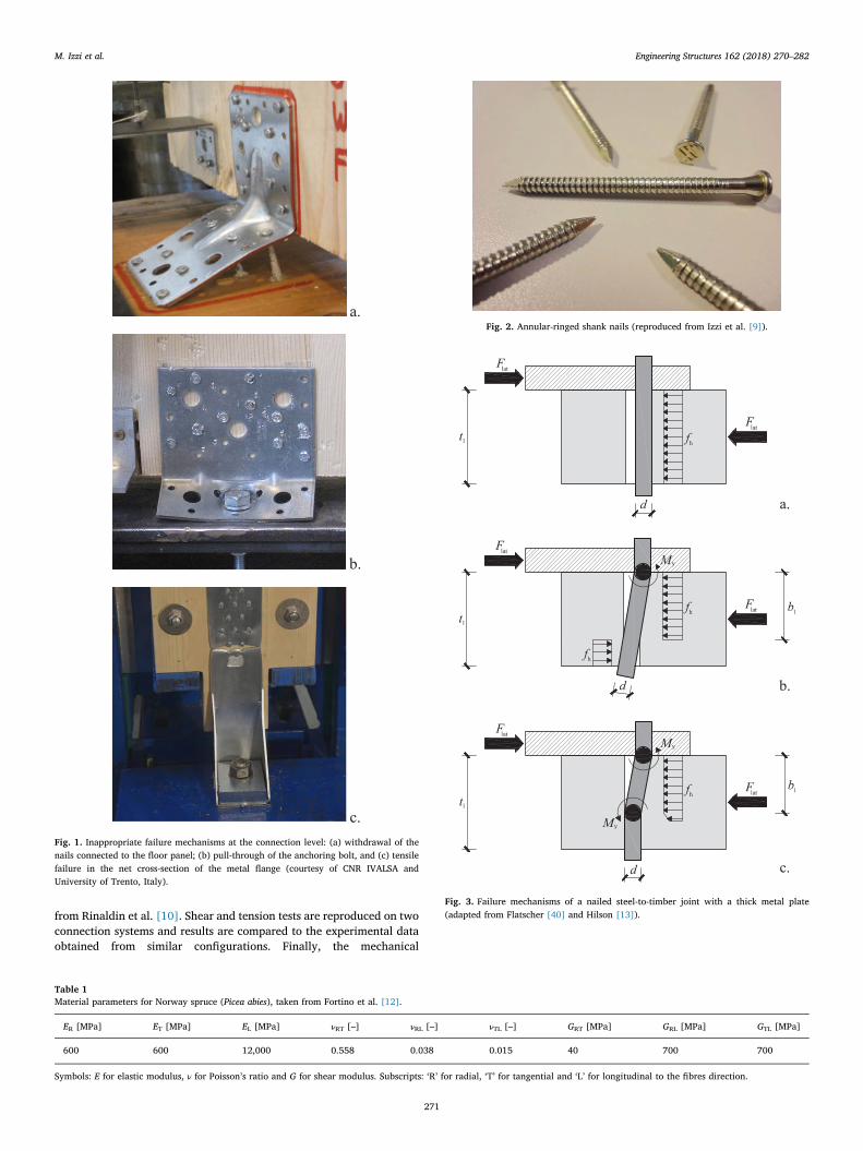
Fig. 2. Annular-ringed shank nails (reproduced from Izzi et al. [9]).
a.
b.
c.
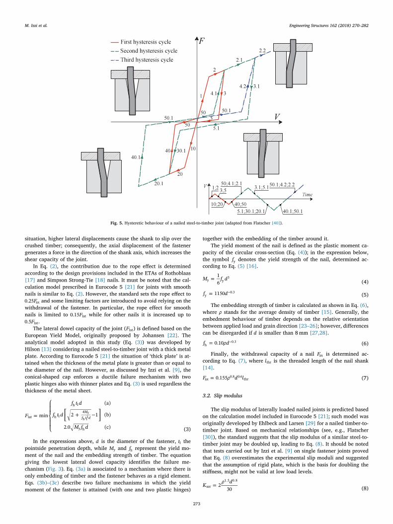
Fig. 3. Failure mechanisms of a nailed steel-to-timber joint with a thick metal plate(adapted from Flatscher [40] and Hilson [13]).
M. Izzi et al. Engineering Structures 162 (2018) 270–282
271

performance when shear and tension loads are applied simultaneouslyis investigated. Analyses are carried out by varying the inclination ofthe load, with respect to the axis of the connector, between 0° (i.e. onlytension) and 90° (i.e. only shear). All the simulations are performedusing ABAQUS software package [11].
2. Model description
The metal connector and the elements where it is anchored aremodelled as 3D solid bodies, meshed with cubic elements with reduced
integration (C3D8R [11]). The CLT wall and the floor panel are in-troduced into the analysis to account for the surface-to-surface contactinteraction and do not influence the behaviour of the metal connector.Therefore, to limit the computational effort required by the simulations,only the top 10mm thickness of those elements are modelled.
The anchoring device has an elasto-plastic isotropic behaviour withYoung’s modulus equal to 210 GPa and Poisson’s ratio set to 0.3. Theproof and ultimate strength of the steel material depend on the con-nector being analysed and cannot be set a priori. In this study, thosestrength properties are defined based on the information given in theEuropean Technical Assessments (ETAs) of the devices considered inthe simulations. Further details are given in Section 5.
The CLT wall is modelled as orthotropic elastic, with materialparameters taken from Fortino et al. [12] (Picea abies, see Table 1). Thefloor element can be either a rigid foundation (a steel profile or aconcrete basement over which the ground floor is assembled) or an-other CLT panel (an intermediate floor). In the first situation, an elasticisotropic material is used with Young’s modulus equal to 210 GPa andPoisson’s ratio set to 0.3, while in the second situation the same ma-terial parameters of the CLT wall are adopted (Table 1).
The nailed steel-to-timber joints are simulated as two-node non-linear hysteretic springs with three degrees of freedom. Two displace-ment components simulate the shear response in parallel and in per-pendicular to the face lamination of the panel. The third one representsthe withdrawal behaviour of the nail under axial actions. Each spring ispinned onto the metal connector (at the nail cap location) and onto theexternal surface of the timber element (at the nail point location),where the boundary conditions of the model are applied.
The displacement components that simulate the shear response of anailed joint are coupled by means of the force-based strength domainwith quadratic interaction given in Eq. (1).
⎜ ⎟ ⎜ ⎟⎛⎝
⎞⎠
+ ⎛⎝
⎞⎠
⩽° °FF
FF
1i i0 ,
y
290 ,
y
2
(1)
In the expression above, Fy is the yield load of the joint, while °F i0 ,and °F i,90 are the shear loads in parallel and perpendicular to the facelamination of the panel at the i-th analysis step. Further information onthis quadratic interaction relationship and how it affects the response ofthe non-linear springs are given in Rinaldin et al. [10].
3. Mechanical properties of nailed joints
Nailed joints in CLT structures are assembled using annular-ringedshank nails (see Fig. 2). Compared to traditional nails with smoothshank, the threaded shank increases the withdrawal capacity, while theconical-shaped cap enhances the clamping to the metal plate and en-forces a ductile failure mechanism with two plastic hinges (see Fig. 3c).
In this study, the mechanical properties of the nailed joints aredetermined according to the calculation models published in literature[13–16]. Furthermore, results are combined with the prescriptions in-cluded in the ETAs of nails currently available on the market [17,18].
3.1. Shear capacity
The shear capacity of laterally loaded joints with annular-ringedshank nails (Fv) is the sum of two contributions. According to Eq. (2),the first term denotes the lateral dowel capacity of the nailed joint (Flat),while the second term represents the ‘rope effect’ and is equal to 50% ofthe withdrawal capacity of the nail (Fax).
= +F F F0.5v lat ax (2)
Nailed joints subjected to shear loads exhibit the so-called ‘ropeeffect’ due to the withdrawal of the deformed fasteners from the timberpanels [19]; as discussed by Izzi et al. [20], this effect is usually acti-vated once a joint attains its lateral dowel capacity Flat. In such
a.
b.
c.Fig. 4. Load-displacement response of a nailed steel-to-timber joint according to (a)Method I, (b) Method II, and (c) Method III.
M. Izzi et al. Engineering Structures 162 (2018) 270–282
272
situation, higher lateral displacements cause the shank to slip over thecrushed timber; consequently, the axial displacement of the fastenergenerates a force in the direction of the shank axis, which increases theshear capacity of the joint.
In Eq. (2), the contribution due to the rope effect is determinedaccording to the design provisions included in the ETAs of Rothoblaas[17] and Simpson Strong-Tie [18] nails. It must be noted that the cal-culation model prescribed in Eurocode 5 [21] for joints with smoothnails is similar to Eq. (2). However, the standard sets the rope effect to
F0.25 ax and some limiting factors are introduced to avoid relying on thewithdrawal of the fastener. In particular, the rope effect for smoothnails is limited to F0.15 lat while for other nails it is increased up to
F0.5 lat.The lateral dowel capacity of the joint (Flat) is defined based on the
European Yield Model, originally proposed by Johansen [22]. Theanalytical model adopted in this study (Eq. (3)) was developed byHilson [13] considering a nailed steel-to-timber joint with a thick metalplate. According to Eurocode 5 [21] the situation of ‘thick plate’ is at-tained when the thickness of the metal plate is greater than or equal tothe diameter of the nail. However, as discussed by Izzi et al. [9], theconical-shaped cap enforces a ductile failure mechanism with twoplastic hinges also with thinner plates and Eq. (3) is used regardless thethickness of the metal sheet.
=
⎧
⎨
⎪
⎩⎪
⎡⎣
+ − ⎤⎦
F
f t d
f t d
M f d
min
(a)
2 1 (b)
2.0 (c)
Mf t dlat
h 1
h 14
y h
y
h 12
(3)
In the expressions above, d is the diameter of the fastener, t1 thepointside penetration depth, while My and fh represent the yield mo-ment of the nail and the embedding strength of timber. The equationgiving the lowest lateral dowel capacity identifies the failure me-chanism (Fig. 3). Eq. (3a) is associated to a mechanism where there isonly embedding of timber and the fastener behaves as a rigid element.Eqs. (3b)–(3c) describe two failure mechanisms in which the yieldmoment of the fastener is attained (with one and two plastic hinges)
together with the embedding of the timber around it.The yield moment of the nail is defined as the plastic moment ca-
pacity of the circular cross-section (Eq. (4)); in the expression below,the symbol fy denotes the yield strength of the nail, determined ac-cording to Eq. (5) [16].
=M f d16y y
3(4)
= −f d1150y0.3
(5)
The embedding strength of timber is calculated as shown in Eq. (6),where ρ stands for the average density of timber [15]. Generally, theembedment behaviour of timber depends on the relative orientationbetween applied load and grain direction [23–26]; however, differencescan be disregarded if d is smaller than 8mm [27,28].
= −f ρd0.10h0.3 (6)
Finally, the withdrawal capacity of a nail Fax is determined ac-cording to Eq. (7), where lthr is the threaded length of the nail shank[14].
=F ρ d l0.155ax0.8 0.6
thr (7)
3.2. Slip modulus
The slip modulus of laterally loaded nailed joints is predicted basedon the calculation model included in Eurocode 5 [21]; such model wasoriginally developed by Ehlbeck and Larsen [29] for a nailed timber-to-timber joint. Based on mechanical relationships (see, e.g., Flatscher[30]), the standard suggests that the slip modulus of a similar steel-to-timber joint may be doubled up, leading to Eq. (8). It should be notedthat tests carried out by Izzi et al. [9] on single fastener joints provedthat Eq. (8) overestimates the experimental slip moduli and suggestedthat the assumption of rigid plate, which is the basis for doubling thestiffness, might not be valid at low load levels.
=Kρ d
230ser
1.5 0.8
(8)
Fig. 5. Hysteretic behaviour of a nailed steel-to-timber joint (adapted from Flatscher [40]).
M. Izzi et al. Engineering Structures 162 (2018) 270–282
273

4. Load-displacement response of nailed joints
This section describes the mechanical relationships used to sche-matize the shear response of a nailed joint. Because tests of single andgroups of nailed joints showed slightly different load-displacement re-sponses, such behaviour is schematized according to three methods(Fig. 4). The first one (labelled ‘Method I’) uses a bilinear relationshipwith a plastic plateau. The second method (labelled ‘Method II’) em-ploys a bilinear relationship with a hardening branch. Finally, the thirdmethod (labelled ‘Method III’) adopts a trilinear elasto-plastic re-lationship.
As discussed in Section 2, the third displacement component of thehysteretic springs models the withdrawal behaviour of the nail. Becausethe rope effect has been already accounted into the shear components
(see Eq. (2)), this contribution is activated only under pure axial loads.Consequently, for the sake of simplicity, it is taken into account in thesimulations as an elastic spring with a brittle failure mechanism afterthe attainment of the maximum load. The stiffness of the withdrawalcomponent is set to 1250 N/mm based on the test results published byIzzi et al. [9], while the maximum load-carrying capacity is determinedas shown in Eq. (7).
4.1. Method I
The first method schematizes the shear response of a nailed jointwith a bilinear elasto-plastic relationship (Fig. 4a). The elastic stiffnessis equal to the slip modulus of the joint Kser, while the shear capacity Fvidentifies the loads at the transition point between the elastic branchand the plastic plateau, and at the ultimate displacement Vu (where Vu isconventionally set to 20mm). In Fig. 4a, Vy denotes the yield
a.
b.
Fig. 6. Comparison between experimental and numerical results of a nailed steel-to-timber joint loaded (a) in parallel and (b) in perpendicular to the face lamination of a CLTpanel (with close-up on the history of total energy).
Table 2Experimental setups of the connection systems tested by Casagrande et al. [6].
Metalconnector
Wall element Floor element Wallanchoring
Flooranchoring
TTF200 CLT panel(ρ=480 kg/m3)
CLT panel(ρ=480 kg/m3)
30 nails(4× 60)
30 nails(4× 60)
WHT620 GLT panel(ρ=420 kg/m3)
Steel foundation(rigid)
52 nails(4× 60)
1 bolt (Ø20)
a.
b.
Fig. 7. Schematics of the connection systems reproduced in the simulations: (a) shear testof the TTF200 and (b) tension test of the WHT620.
M. Izzi et al. Engineering Structures 162 (2018) 270–282
274

displacement and Vmax the displacement at which Fv is attained, being= =V V F K/y max v ser.The assumption of elastic behaviour until the attainment of the
shear capacity is acceptable since shear tests of single nailed jointsshowed a linear fashion until 90% of the shear capacity Fv [9]. How-ever, the displacement at which Fv is attained in the tests is highercompared to the values obtained with this bilinear method, possiblyleading to incorrect predictions of Vy (and Vmax) in the analyses.
4.2. Method II
The second method schematizes the shear response of a nailed jointbased on an elasto-plastic relationship with a hardening branch(Fig. 4b) and is derived taking as a reference the tests of Casagrandeet al. [6]. The elastic stiffness is equal to the slip modulus of the jointKser, while the shear capacity Fv identifies both the maximum load andthe load at the ultimate displacement ( =V Vmax u). The yield load isequal to the lateral dowel capacity Flat, as confirmed by an independentnumerical study carried out by Izzi et al. [20] on similar test data. Fi-nally, the slope of the hardening branch is determined by assuming thatthe shear capacity is attained at = =V V V6max u y, being =V F K/y lat ser.
4.3. Method III
The third method schematizes the shear response of a nailed jointusing a trilinear elasto-plastic relationship (Fig. 4c) and is derived basedon the tests of Ceccotti et al. [31]. The slope of the elastic branch isequal to the slip modulus Kser, while its maximum load is equal to 40%of Fv . The first inelastic branch has a hardening behaviour and max-imum load equal to Fv. Its slope is given by the line drawn through thepoints at 40% and 60% of the shear capacity Fv ; the first point lays onthe elastic branch, while the second point belongs to the line drawnthrough the origin of the axis with stiffness equal to K2/3 ser. The secondinelastic branch has a plastic behaviour until the ultimate displacementVu (conventionally set to 20mm) and is activated after the attainment ofthe maximum load, i.e. at =V F K1.9 /max v ser
4.4. Hysteretic behaviour
Nailed joints subjected to cyclic loads exhibit the pinching effectdue to the reduction of stiffness at small displacement amplitudes, whena cavity is formed around the fastener due to timber crushing. Stiffnessincreases at higher displacement levels, when the nail comes again intocontact with the surrounding timber [32].
The hysteretic behaviour of a nailed joint is schematized accordingto the piecewise-linear law of Fig. 5. The backbone curve (composed ofbranches #1, #2, #10, and #20) is assembled based on the methodsdiscussed in Sections 4.1–4.3. If the joint is unloaded from a positivedisplacement, branch #3 is followed; on the contrary, branch #40 isfollowed if the unloading starts from a negative displacement. Branches#5 and #50 model the gap between the nail shank and the surroundingtimber. Finally, branches #30 and #4 simulate the mechanical beha-viour when the nail comes again into contact with timber.
The unloading (#3, #5, and #30) and reloading (#40, #50, and #4)paths depend on the plastic deformed configuration of the joint. Sincetypical nailed joints are too slender to attain a failure mechanism withonly embedding of timber (see Fig. 3a), this situation is disregarded inthe following discussion. In any case, this failure mechanism should be
Table 3Mechanical properties of a nailed steel-to-timber joint, according to Eqs. (2)–(8).
Joint type My [kNmm] fh [MPa] Fax [kN] Flat [kN] Fv [kN] Kser [kN/mm]
Nailed joint in CLT (for the TTF200) 8.09 31.67 2.19 2.03 3.12 2.13Nailed joint in GLT (for the WHT620) 8.09 27.71 1.97 1.89 2.88 1.74
Table 4Typical input parameters of a nailed steel-to-timber joint, when the load-displacementresponse is defined according to Method I.
Input parameters for Method I
Connection with TTF200 Connection with WHT620
Kser [kN/mm] 2.13 1.74Fv [kN] 2.22a 1.94a
Slope #1 Kser Kser
Slope #3 5× Kser 5× Kser
Slope #4 2.5× Kser 2.5× Kser
Separation #1-#2 Fv FvSeparation #3-#5 5%× Fv 5%× FvSeparation #50-#4 16%× Fv 16%× Fv
a Effective strength property, obtained by multiplying the shear capacity Fv given inTable 3 by the effective factor keff defined in Equation (12); keff=0.71 for the TTF200 (30nails) and keff=0.67 for the WHT620 (52 nails).
a.
b. Fig. 8. Comparison between experimental and numerical results of (a) the TTF200 loadedin shear and (b) the WHT620 loaded in tension, when the actual mechanical properties ofthe nailed joints are used.
M. Izzi et al. Engineering Structures 162 (2018) 270–282
275
carefully avoided in seismic applications due to the slack effect (zerostrength and stiffness) and the sudden reduction of the load-carryingcapacity caused by timber crushing.
The slopes of branches #3 and #4 are defined based on the cyclictests carried out by Izzi et al. [9] and are set to 5 and 2.5 times Kser,respectively. Similarly, the load at the transition point between bran-ches #3 and #5 is assessed from the same test data and is set to 5% ofFi, where Fi is the load attained on the backbone curve at the i-thanalysis step. Finally, the load at the transition point between branches#5 and #30 is defined using an analytical procedure derived fromHilson [13] and is equal to F F/#5/#30 v times Fi, being F#5/#30 (Eq. (9)) theload taken by the deformed nail (in bending) at the hysteresis cyclewhere the shear capacity Fv is attained.
=F M b/#5/#30 y 1 (9)
In the equation above, My denotes the yield moment of the nail,while b1 represents the effective penetration depth of the joint, which
depends on its failure mechanism. In this study, b1 is determined as inEq. (10) when failure occurs for embedding of timber and yielding ofthe nail with one plastic hinge (Fig. 3b), while Eq. (11) is used whentwo plastic hinges have formed (Fig. 3c).
= ⎡
⎣⎢ + − ⎤
⎦⎥b t
Mf t d
24
11 1y
h 12
(10)
=bMf d
21y
h (11)
The hysteresis model discussed above is validated by comparisonwith two cyclic shear tests of nailed joints loaded in parallel and per-pendicular to the face lamination of a CLT panel. The experimentalresults taken as a reference are obtained from Izzi et al. [9]. Thebackbone curves used in the springs are assessed from the tests asprescribed in EN 12512 [33]. Fig. 6 shows the outcomes of this
a.
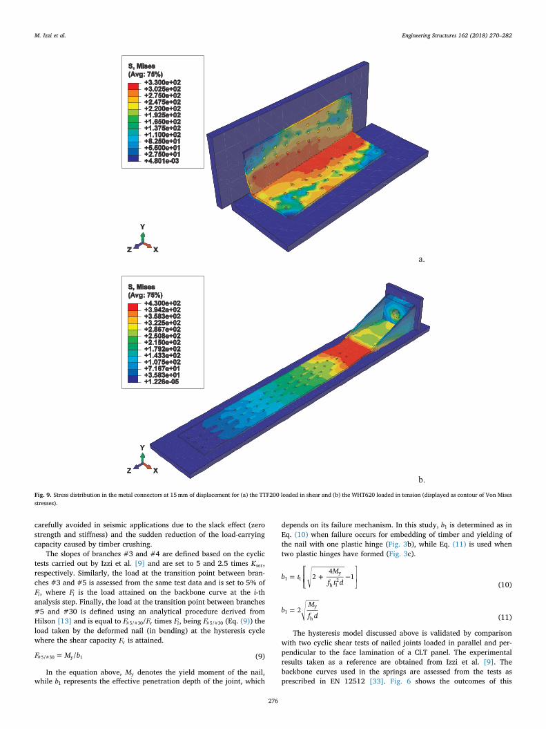
b. Fig. 9. Stress distribution in the metal connectors at 15mm of displacement for (a) the TTF200 loaded in shear and (b) the WHT620 loaded in tension (displayed as contour of Von Misesstresses).
M. Izzi et al. Engineering Structures 162 (2018) 270–282
276
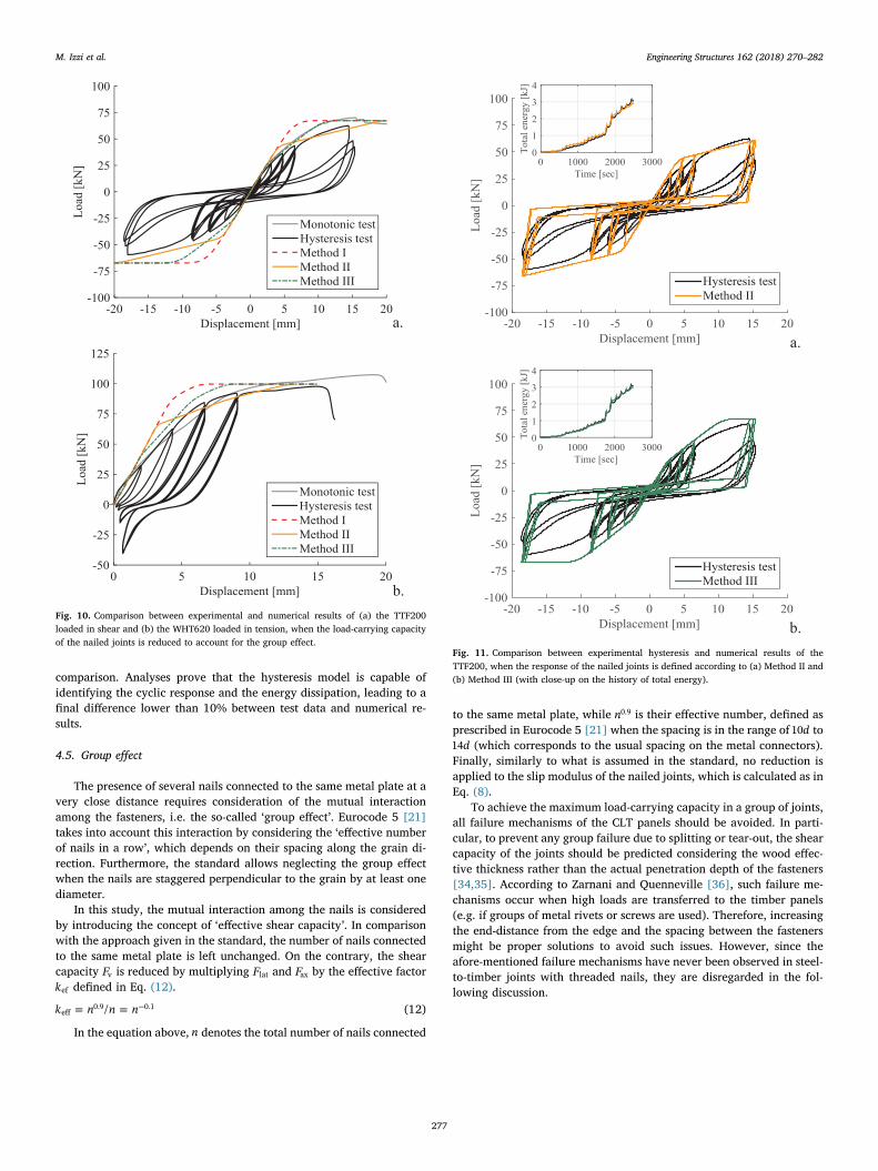
comparison. Analyses prove that the hysteresis model is capable ofidentifying the cyclic response and the energy dissipation, leading to afinal difference lower than 10% between test data and numerical re-sults.
4.5. Group effect
The presence of several nails connected to the same metal plate at avery close distance requires consideration of the mutual interactionamong the fasteners, i.e. the so-called ‘group effect’. Eurocode 5 [21]takes into account this interaction by considering the ‘effective numberof nails in a row’, which depends on their spacing along the grain di-rection. Furthermore, the standard allows neglecting the group effectwhen the nails are staggered perpendicular to the grain by at least onediameter.
In this study, the mutual interaction among the nails is consideredby introducing the concept of ‘effective shear capacity’. In comparisonwith the approach given in the standard, the number of nails connectedto the same metal plate is left unchanged. On the contrary, the shearcapacity Fv is reduced by multiplying Flat and Fax by the effective factorkef defined in Eq. (12).
= = −k n n n/eff0.9 0.1 (12)
In the equation above, n denotes the total number of nails connected
to the same metal plate, while n0.9 is their effective number, defined asprescribed in Eurocode 5 [21] when the spacing is in the range of d10 to
d14 (which corresponds to the usual spacing on the metal connectors).Finally, similarly to what is assumed in the standard, no reduction isapplied to the slip modulus of the nailed joints, which is calculated as inEq. (8).
To achieve the maximum load-carrying capacity in a group of joints,all failure mechanisms of the CLT panels should be avoided. In parti-cular, to prevent any group failure due to splitting or tear-out, the shearcapacity of the joints should be predicted considering the wood effec-tive thickness rather than the actual penetration depth of the fasteners[34,35]. According to Zarnani and Quenneville [36], such failure me-chanisms occur when high loads are transferred to the timber panels(e.g. if groups of metal rivets or screws are used). Therefore, increasingthe end-distance from the edge and the spacing between the fastenersmight be proper solutions to avoid such issues. However, since theafore-mentioned failure mechanisms have never been observed in steel-to-timber joints with threaded nails, they are disregarded in the fol-lowing discussion.
a.
b. Fig. 10. Comparison between experimental and numerical results of (a) the TTF200loaded in shear and (b) the WHT620 loaded in tension, when the load-carrying capacityof the nailed joints is reduced to account for the group effect.
a.
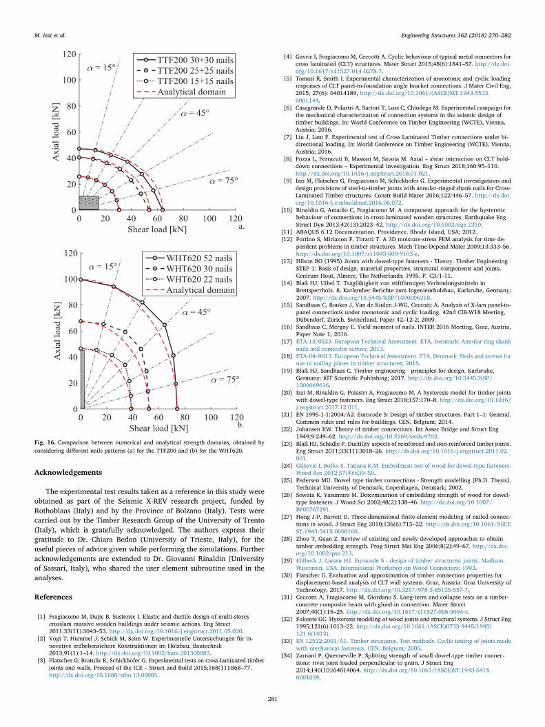
b. Fig. 11. Comparison between experimental hysteresis and numerical results of theTTF200, when the response of the nailed joints is defined according to (a) Method II and(b) Method III (with close-up on the history of total energy).
M. Izzi et al. Engineering Structures 162 (2018) 270–282
277

5. Numerical analyses
Shear and tension tests are reproduced on two wall-to-floor con-nections tested at the University of Trento (Italy) [6]. The first system isassembled using a TTF200 angle bracket [37], anchored to two CLTpanels with 60 nails (30 in each element). The second connection isassembled with a WHT620 hold-down [38], anchored to a Glue-Lami-nated Timber (GLT) panel with 52 nails and to a steel foundation with abolt. In this second case, to prevent local buckling and to distribute theload over a larger surface, the anchoring to the foundation isstrengthened with a thick washer plate. Both setups employ annular-ringed shank nails [17] with diameter d =4.0mm, penetration deptht1 =54mm and threaded length lthr =44mm. Further details of theseconnections are given in Table 2, while Fig. 7 schematizes the setupsused in the tests.
Based on the requirements given in the ETAs of the connectors, theangle bracket is made of S250GD steel with proof strength equal to250MPa and ultimate strength equal to 330MPa. The hold-down ismade of S355 steel with proof and ultimate strength equal to 355MPaand 430MPa, respectively. In both cases, the ultimate strength is at-tained after a 20% plastic strain. The average density of timber, mea-sured from the actual specimens, is 480 kg/m3 for CLT and 420 kg/m3
for GLT. Table 3 summarizes the mechanical properties of the nailed
joints, assessed as discussed in Section 3, while Table 4 shows the ty-pical input parameters used in the analyses.
5.1. Simulations under monotonic loading conditions
The mechanical behaviour under monotonic conditions is in-vestigated by considering the angle bracket loaded in shear and thehold-down in tension. The analyses are carried out by applying amonotonic displacement to the wall panel (up to 20mm and 15mm,respectively), while the floor element is restrained to its original posi-tion.
The first set of simulations does not consider the reduction ofstrength due to the group effect. The load-displacement response of thenailed joints is defined according to Method I, while the mechanicalproperties are determined as discussed in Section 3. As pointed out inSection 3.2, shear tests of single nailed steel-to-timber joints high-lighted that Eq. (8) overestimates the experimental slip moduli; there-fore, analyses are also carried out considering a factor 1 instead of thefactor 2 prescribed in Eurocode 5 [21].
Fig. 8 compares experimental results (solid grey line for themonotonic test and solid black line for the hysteresis test) and numer-ical predictions when Kser is calculated using a factor 2 (dash-dotted
a.
b. Fig. 12. Comparison between experimental hysteresis and numerical results of theWHT620, when the response of the nailed joints is defined according to (a) Method II and(b) Method III (with close-up on the history of total energy).
a.
b. Fig. 13. Load-displacement response of the TTF200 (a) with α =90° and (b) withα =45°, when the number of nails varies from 30+30 (solid line) to 15+ 15 (dash-dotted line).
M. Izzi et al. Engineering Structures 162 (2018) 270–282
278

blue line) and a factor 1 (dashed red line). Furthermore, Fig. 9 displaysthe stress distribution in the metal connectors at 15mm of displace-ment. The angle bracket shows local buckling, while the hold-downexhibits a tensile failure in the metal flange (which justifies the soft-ening behaviour in Fig. 8b). Results of the simulations point out that thefactor 1 provides accurate predictions of the elastic stiffness, while thefactor 2 leads to unrealistic stiff responses. Furthermore, in both con-nections, the numerical predictions lead to higher load-carrying capa-cities compared to the reference test results.
Simulations are subsequently repeated by considering also the othertwo methods discussed in Section 4 and by including the reduction ofstrength that accounts for the group effect; all the slip moduli are cal-culated using a factor 1 instead of the factor 2 given in Eq. (8).
Fig. 10 compares experimental and numerical results when theshear response is defined according to Method I (dashed red line), II(solid orange line) and III (dash-dotted green line). Simulations showthat Method II and III provide reliable predictions of the global per-formance; on the other hand, Method I exhibits similar load-carryingcapacities, although it leads to a less accurate identification of theglobal behaviour.
5.2. Simulations under cyclic loading conditions
Cyclic shear and tension tests are reproduced on the previous nu-merical models, using the same input data of the monotonic analyses.Figs. 11 and 12 compare experimental (black line) and numerical re-sults when the shear response of the nailed joints is defined according toMethod II (orange line) and III (green line). Both methods provide re-liable predictions of the hysteretic response and the energy dissipation.Method I is not taken into account in this comparison since it providesless accurate results and leads to higher energy dissipations (approxi-mately 10% higher than in the experimental tests).
The plastic deformations in the metal connectors affect the perfor-mance under cyclic loading conditions. As highlighted in Section 5.1,the TTF200 angle bracket shows local buckling close to the bendedarea; this reduces the global stiffness of the connection (which is lowerthan the net stiffness resulting from the nailed joints) and increases itsductility. Similarly, the WHT620 hold-down loaded in tension exhibitssome plastic deformations in the bottom part of the metal flange, whichreduce the stiffness at large displacement amplitudes and influence theshape of the hysteresis cycles.
5.3. Simulations under bi-axial loading conditions
The mechanical performance under the simultaneous application ofshear and tension loads (bi-axial loading condition) is examined via aparametric numerical study. Simulations are carried out by varying theinclination of the load, with respect to the axis of the connector, be-tween 0° (only axial load) and 90° (only shear load). Analyses aresubsequently repeated by reducing the number of nails used in theconnections. For each connector, three nails patterns are considered:30+ 30 (original pattern), 25+25, and 15+15 nails for the anglebracket; 52 (original pattern), 30 and 22 nails for the hold-down. Anultimate displacement equal to 15mm [39] is considered in all cases;furthermore, for the sake of simplicity, the load-displacement responseof the nailed joints is always defined according to Method II.
Fig. 13 shows the loading curves of the angle bracket when α =90°and α =45°, while Fig. 14 presents similar results for the hold-downwhen α =0° and α =45°. Finally, Fig. 15 displays the stress distribu-tion in the connectors at the end of the simulations when α =45°.Results highlight that the loading direction influences both the stiffnessand the load-carrying capacity of the connections.
The maximum loads attained in the analyses (at α =0°, 15°, 30°,45°, 60°, 75°, and 90°) are used to create the strength domains shown inFig. 16 (black lines). Each point is determined as either the maximum ofthe loading curve or the load at 15mm of displacement, whicheveroccurs first. Numerical results are subsequently compared to the ana-lytical strength domains of the connections, defined as suggested in theETAs (Eq. (13), red dashed lines).
⎜ ⎟ ⎜ ⎟⎛⎝
⎞⎠
+ ⎛⎝
⎞⎠
⩽°
°
°
°
FF
FF
10
0 ,max
290
90 ,max
2
(13)
In the equation above, °F0 ,max and °F90 ,max represent the maximumstrength capacities in the axial and shear direction, while °F0 and °F90denote the actual loads applied to the connection. In Fig. 16, values of
°F0 ,max and °F90 ,max are set to numerical predictions attained under onlyaxial and shear loads, respectively. Based on the comparisons presentedin Fig. 16, numerical results validate the strength domains suggested inthe ETAs of the metal connectors, confirming a quadratic interactionrelationship between shear and tension loads.
a.
b. Fig. 14. Load-displacement response of the WHT620 (a) with α =0° and (b) withα =45°, when the number of nails varies from 52 (solid line) to 22 (dash dotted line).
M. Izzi et al. Engineering Structures 162 (2018) 270–282
279

6. Conclusions
This paper proposes a numerical model capable of predicting themechanical behaviour and the failure mechanism of typical wall-to-floor connections used in CLT structures. Great efforts have been de-voted to develop a simplified hysteresis that simulates the response of anailed steel-to-timber joint in CLT. Shear and tension tests are re-produced on connections with angle brackets and hold-downs; nu-merical results are then compared to the experimental test data of si-milar configurations, leading to limited differences.
Results of the monotonic analyses highlight that the analyticalmodel prescribed in Eurocode 5 [21] to predict the slip modulus of anailed steel-to-timber joint overestimates the stiffness at the connection
level. Furthermore, simulations proved that it is necessary to considerthe group effect in nailed joints (and to reduce their load-carrying ca-pacity) to obtain reliable predictions of the mechanical behaviour of theconnections.
Analyses carried out under cyclic conditions exhibit an excellentmatch with the reference test results, in terms of hysteretic behaviourand energy dissipation. Finally, the performance under bi-axial loadingconditions is investigated by varying the inclination of the load and thenails pattern used to fasten the connectors to the wall and floor panels.Simulations showed that the loading direction has a significant influ-ence on the stiffness and load-carrying capacity, and a quadratic in-teraction relationship is observed between shear and tension loads.
a.
b.
Fig. 15. Stress distribution in the metal connectors at15mm of displacement when α =45° (a) for the TTF200and (b) for the WHT620 (displayed as contour of VonMises stresses).
M. Izzi et al. Engineering Structures 162 (2018) 270–282
280
Acknowledgements
The experimental test results taken as a reference in this study wereobtained as part of the Seismic X-REV research project, funded byRothoblaas (Italy) and by the Province of Bolzano (Italy). Tests werecarried out by the Timber Research Group of the University of Trento(Italy), which is gratefully acknowledged. The authors express theirgratitude to Dr. Chiara Bedon (University of Trieste, Italy), for theuseful pieces of advice given while performing the simulations. Furtheracknowledgements are extended to Dr. Giovanni Rinaldin (Universityof Sassari, Italy), who shared the user element subroutine used in theanalyses.
References
[1] Fragiacomo M, Dujic B, Sustersic I. Elastic and ductile design of multi-storeycrosslam massive wooden buildings under seismic actions. Eng Struct2011;33(11):3043–53. http://dx.doi.org/10.1016/j.engstruct.2011.05.020.
[2] Vogt T, Hummel J, Schick M, Seim W. Experimentelle Untersuchungen für in-novative erdbebensichere Konstruktionen im Holzbau. Bautechnik2013;91(1):1–14. http://dx.doi.org/10.1002/bate.201300083.
[3] Flatscher G, Bratulic K, Schickhofer G. Experimental tests on cross-laminated timberjoints and walls. Proceed of the ICE – Struct and Build 2015;168(11):868–77.http://dx.doi.org/10.1680/stbu.13.00085.
[4] Gavric I, Fragiacomo M, Ceccotti A. Cyclic behaviour of typical metal connectors forcross laminated (CLT) structures. Mater Struct 2015;48(6):1841–57. http://dx.doi.org/10.1617/s11527-014-0278-7.
[5] Tomasi R, Smith I. Experimental characterization of monotonic and cyclic loadingresponses of CLT panel-to-foundation angle bracket connections. J Mater Civil Eng,2015; 27(6): 04014189, http://dx.doi.org/10.1061/(ASCE)MT.1943-5533.0001144.
[6] Casagrande D, Polastri A, Sartori T, Loss C, Chiodega M. Experimental campaign forthe mechanical characterization of connection systems in the seismic design oftimber buildings. In: World Conference on Timber Engineering (WCTE), Vienna,Austria; 2016.
[7] Liu J, Lam F. Experimental test of Cross Laminated Timber connections under bi-directional loading. In: World Conference on Timber Engineering (WCTE), Vienna,Austria; 2016.
[8] Pozza L, Ferracuti B, Massari M, Savoia M. Axial – shear interaction on CLT hold-down connections – Experimental investigation. Eng Struct 2018;160:95–110.http://dx.doi.org/10.1016/j.engstruct.2018.01.021.
[9] Izzi M, Flatscher G, Fragiacomo M, Schickhofer G. Experimental investigations anddesign provisions of steel-to-timber joints with annular-ringed shank nails for Cross-Laminated Timber structures. Constr Build Mater 2016;122:446–57. http://dx.doi.org/10.1016/j.conbuildmat.2016.06.072.
[10] Rinaldin G, Amadio C, Fragiacomo M. A component approach for the hystereticbehaviour of connections in cross-laminated wooden structures. Earthquake EngStruct Dyn 2013;42(13):2023–42. http://dx.doi.org/10.1002/eqe.2310.
[11] ABAQUS 6.12 Documentation. Providence, Rhode Island, USA; 2012.[12] Fortino S, Mirianon F, Toratti T. A 3D moisture-stress FEM analysis for time de-
pendent problems in timber structures. Mech Time-Depend Mater 2009;13:333–56.http://dx.doi.org/10.1007/s11043-009-9103-z.
[13] Hilson BO (1995) Joints with dowel-type fasteners - Theory. Timber EngineeringSTEP 1: Basis of design, material properties, structural components and joints,Centrum Hout, Almere, The Netherlands; 1995. P. C3/1-11.
[14] Blaß HJ, Uibel T. Tragfähigkeit von stiftförmigen Verbindungsmitteln inBrettsperrholz. 8, Karlsruher Berichte zum Ingenieurholzbau, Karlsruhe, Germany;2007. http://dx.doi.org/10.5445/KSP/1000006318.
[15] Sandhaas C, Boukes J, Van de Kuilen J-WG, Ceccotti A. Analysis of X-lam panel-to-panel connections under monotonic and cyclic loading. 42nd CIB-W18 Meeting,Dübendorf, Zürich, Swizerland, Paper 42–12-2; 2009.
[16] Sandhaas C, Mergny E. Yield moment of nails. INTER 2016 Meeting, Graz, Austria,Paper Note 1; 2016.
[17] ETA-13/0523. European Technical Assessment. ETA, Denmark: Annular ring shanknails and connector screws; 2013.
[18] ETA-04/0013. European Technical Assessment. ETA, Denmark: Nails and screws foruse in nailing plates in timber structures; 2015.
[19] Blaß HJ, Sandhaas C. Timber engineering - principles for design. Karlsruhe,Germany: KIT Scientific Publishing; 2017. http://dx.doi.org/10.5445/KSP/1000069616.
[20] Izzi M, Rinaldin G, Polastri A, Fragiacomo M. A hysteresis model for timber jointswith dowel-type fasteners. Eng Struct 2018;157:170–8. http://dx.doi.org/10.1016/j.engstruct.2017.12.011.
[21] EN 1995-1-1:2004/A2. Eurocode 5: Design of timber structures. Part 1–1: General.Common rules and rules for buildings. CEN, Belgium; 2014.
[22] Johansen KW. Theory of timber connections. Int Assoc Bridge and Struct Eng1949;9:249–62. http://dx.doi.org/10.5169/seals-9703.
[23] Blaß HJ, Schädle P. Ductility aspects of reinforced and non-reinforced timber joints.Eng Struct 2011;33(11):3018–26. http://dx.doi.org/10.1016/j.engstruct.2011.02.001.
[24] Glišović I, Boško S, Tatjana K-M. Embedment test of wood for dowel-type fasteners.Wood Res 2012;57(4):639–50.
[25] Pedersen MU. Dowel type timber connections - Strength modelling [Ph.D. Thesis].Technical University of Denmark, Copenhagen, Denmark; 2002.
[26] Sewata K, Yasumura M. Determination of embedding strength of wood for dowel-type fasteners. J Wood Sci 2002;48(2):138–46. http://dx.doi.org/10.1007/BF00767291.
[27] Hong J-P, Barrett D. Three-dimensional finite-element modeling of nailed connec-tions in wood. J Struct Eng 2010;136(6):715–22. http://dx.doi.org/10.1061/ASCEST.1943-541X.0000160.
[28] Zhou T, Guan Z. Review of existing and newly developed approaches to obtaintimber embedding strength. Prog Struct Mat Eng 2006;8(2):49–67. http://dx.doi.org/10.1002/pse.213.
[29] Ehlbeck J, Larsen HJ. Eurocode 5 - design of timber structures: joints. Madison,Wisconsin, USA: International Workshop on Wood Connectors; 1993.
[30] Flatscher G. Evaluation and approximation of timber connection properties fordisplacement-based analysis of CLT wall systems. Graz, Austria: Graz University ofTechnology; 2017. http://dx.doi.org/10.3217/978-3-85125-557-7.
[31] Ceccotti A, Fragiacomo M, Giordano S. Long-term and collapse tests on a timber-concrete composite beam with glued-in connection. Mater Struct2007;40(1):15–25. http://dx.doi.org/10.1617/s11527-006-9094-z.
[32] Foliente GC. Hysteresis modeling of wood joints and structural systems. J Struct Eng1995;121(6):1013–22. http://dx.doi.org/10.1061/(ASCE)0733-9445(1995)121:6(1013).
[33] EN 12512:2001/A1. Timber structures. Test methods. Cyclic testing of joints madewith mechanical fasteners. CEN, Belgium; 2005.
[34] Zarnani P, Quenneville P. Splitting strength of small dowel-type timber connec-tions: rivet joint loaded perpendicular to grain. J Struct Eng2014;140(10):04014064. http://dx.doi.org/10.1061/(ASCE)ST.1943-541X.0001039.
a.
b.
Fig. 16. Comparison between numerical and analytical strength domains, obtained byconsidering different nails patterns (a) for the TTF200 and (b) for the WHT620.
M. Izzi et al. Engineering Structures 162 (2018) 270–282
281
[35] Zarnani P, Quenneville P. Group tear-out in small-dowel-type timber connections:brittle and mixed failure modes of multinail joints. J Struct Eng2015;141(2):04014110. http://dx.doi.org/10.1061/(ASCE)ST.1943-541X.0001053.
[36] Zarnani P, Quenneville P. New design approach for controlling brittle failure modesof small-dowel-type connections in Cross-laminated Timber (CLT). Constr BuildMater 2015;100:172–82. http://dx.doi.org/10.1016/j.conbuildmat.2015.09.049.
[37] ETA-11/0496. European Technical Assessment. Three-dimensional nailing plate(Angle bracket for timber-to-timber or timber-to-concrete or steel connections).ETA, Denmark; 2014.
[38] ETA-11/0086. European Technical Assessment. Three-dimensional nailing plate(Angle brackets and hold-downs for timber-to-timber or timber-to-concrete or steelconnections). ETA, Denmark; 2015.
[39] EN 26891. Timber structures. Joints made with mechanical fasteners. Generalprinciples for the determination of strength and deformation characteristics. CEN,Belgium; 1991.
[40] Flatscher G. Außergewöhnliche Einwirkung ,Erdbeben - Überlegungen zur ver-suchstechnischen Erfassung der Verbindungstechnik im Holz-Massivbau [MSThesis]. Graz University of Technology, Graz, Austria; 2010.
M. Izzi et al. Engineering Structures 162 (2018) 270–282
282