models 106-pg-bpc / 206-pg-bpc booster pump control...
TRANSCRIPT

www.singervalve.com167
Models 106-PG-BPC / 206-PG-BPC
Booster Pump Control Valve – Single Chamber
Pu
mp
Co
ntro
l
2013.1
KEY FEATURES• Substantially reduces pump starting
and stopping surges
• Separate opening and closing speed controls
• Cost effective pump control system
• Optional internal mechanical drop check reduces power failure surge
Product OverviewThe 106-PG-BPC or 206-PG-BPC booster pump control valve is installed in-line directly downstream of the pump discharge.
The valve is normally closed, and, on pump start-up, a pilot solenoid is energized to slowly open the valve, at a rate governed by the opening speed control. The pipeline low is gradually increased.
When shut-down is required, the pilot solenoid is de-energized to close the main valve and reduce the low. The pump is kept running while the booster pump control valve slowly closes. When the valve is almost fully closed and low is virtually stopped, a cam triggers the limit switch to stop the pump.
With the internal drop check option, the built-in mechanical drop check closes immediately when the low stops, regardless of the valve position. Whether due to a control malfunction, normal operation or a pump motor power failure, by closing before low reverses, surges are minimized.
The single chamber construction facilitates supplemental modulating functions such as pressure sustaining, pressure reducing, rate of low control. Being a single chamber design, the control forces are generated by the differential across the valve. When a modulating function is included there are more positive initial closing results.
Typical Application
Singer model 106-RPSPressure Relief Valve
Singer model 106-PG-BPCBooster Pump Control valveSingle Chamber with Internal Drop Check (optional)
Isolation valve
Booster pump
206-PG-BPC Globe
168
Models 106-PG-BPC / 206-PG-BPC
Booster Pump Control Valve – Single Chamber
Pu
mp
Co
ntro
l
2013.1
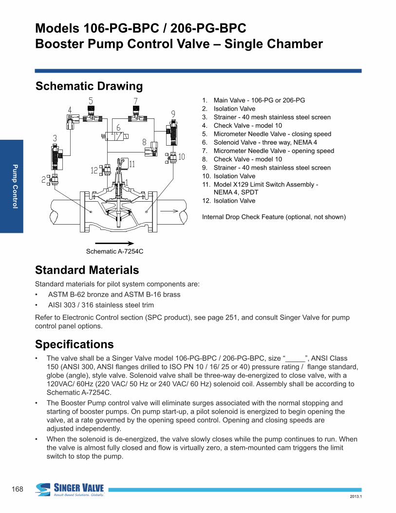
1. Main Valve - 106-PG or 206-PG
2. Isolation Valve
3. Strainer - 40 mesh stainless steel screen
4. Check Valve - model 10
5. Micrometer Needle Valve - closing speed
6. Solenoid Valve - three way, NEMA 4
7. Micrometer Needle Valve - opening speed
8. Check Valve - model 10
9. Strainer - 40 mesh stainless steel screen
10. Isolation Valve
11. Model X129 Limit Switch Assembly - NEMA 4, SPDT
12. Isolation Valve
Internal Drop Check Feature (optional, not shown)
Schematic Drawing
Standard MaterialsStandard materials for pilot system components are:
• ASTM B-62 bronze and ASTM B-16 brass
• AISI 303 / 316 stainless steel trim
Refer to Electronic Control section (SPC product), see page 251, and consult Singer Valve for pump control panel options.
Speciications • The valve shall be a Singer Valve model 106-PG-BPC / 206-PG-BPC, size “_____”, ANSI Class
150 (ANSI 300, ANSI langes drilled to ISO PN 10 / 16/ 25 or 40) pressure rating / lange standard, globe (angle), style valve. Solenoid valve shall be three-way de-energized to close valve, with a 120VAC/ 60Hz (220 VAC/ 50 Hz or 240 VAC/ 60 Hz) solenoid coil. Assembly shall be according to Schematic A-7254C.
• The Booster Pump control valve will eliminate surges associated with the normal stopping and starting of booster pumps. On pump start-up, a pilot solenoid is energized to begin opening the valve, at a rate governed by the opening speed control. Opening and closing speeds are adjusted independently.
• When the solenoid is de-energized, the valve slowly closes while the pump continues to run. When the valve is almost fully closed and low is virtually zero, a stem-mounted cam triggers the limit switch to stop the pump.
Schematic A-7254C

www.singervalve.com169
Models 106-PG-BPC / 206-PG-BPC
Booster Pump Control Valve – Single Chamber
Pu
mp
Co
ntro
l
2013.1
• Refer to Main Valve section, page 11, 106-PG (or 206-PG) for detailed information pertaining to valve sizes and materials, selection criteria and speciications.
• Refer to Pilot and Accessories section, page 279, Micrometer Flow Control Valves for detailed information pertaining to materials and speciications. Solenoid speciication information is available from Singer Valve only at this time.
Selection Summary1. The model PG-BPC, booster pump control valve incurs continuous head loss while the pump
is operating. Refer to the 106 or 206 performance curves (see Technical & Sizing Information section, page 284). Use drooping portion of curve. Select the smallest size with a pressure drop that is acceptable.
2. With no modulating pilot functions added, care should be exercised not to oversize the valve, especially if pumps are operating in parallel. With very low differential across the valve, initial closing speed will be slow. Sections 106-PG and 206-PG (Main Valve section, page 11), provide speciications and details of construction of the standard main valves while bulletin IDC - Internal Drop Check (see Main Valve Options section, page 83) provides details on the internal mechanical check option.
3. Standard coniguration provides for NEMA 4 watertight enclosures for the Honeywell model OP-AR, Single Pole Double Throw limit switch and the ASCO solenoid with 120VAC / 60Hz (or 220VAC / 50HZ or 240VAC / 60Hz) coil. For other electrical service or higher pressure ratings consult with Singer Valve. A manual override is available upon request.
Ordering InstructionsRefer to page 293 for the order form and ordering instructions.
Additionally, include the following information for this product:
1. Full port (106) or reduced port (206)
2. Solenoid voltage
3. Maximum inlet pressure

170
Models 106-PG-BPC / 206-PG-BPC
Booster Pump Control Valve – Single Chamber
Pu
mp
Co
ntro
l
2013.1
*CV = USGPM at 1 psi pressure drop
**KV = L / s at 1 bar pressure drop
(Q=CV P )
106-PG-BPCFlow Coeficient C
v
(See 106-PG in Main Valve Section for other Valve Data)
Size (inches) 2 in 2-1/2 in 3 in 4 in
Size ( mm) 50 mm 65 mm 80 mm 100 mm
Cv1 55 80 110 200
Kv2 13 19 26 47
206-PG-BPCFlow Coeficient C
v
(See 206-PG in Main Valve Section for other Valve Data)
Size (inches) 4 in 6 in 8 in 10 in
Size ( mm) 100 mm 150 mm 200 mm 250 mm
Cv1 150 250 505 985
Kv2 36 60 120 230
106-PG-BPCFlow Coeficient C
v
(See 106-PTC in Main Valve section for other valve data)
Size (inches) 6 in 8 in 10 in 12 in 14 in 16 in 20 in 24 in 36 in
Size (mm) 150 mm 200 mm 250 mm 300 mm 350 mm 400 mm 500 mm 600 mm 900 mm
Cv1 460 800 1300 2100 2575 3300 5100 7600 16340
Kv2 110 190 310 500 610 780 1210 1800 3875
206-PG-BPCFlow Coeficient C
v
(See 206-PTC in Main Valve section for other valve data)
Size (inches) 12 in 16 in 18 in 20 in 24 x 16 in 24 x 20 in 36 x 24 in 40 x 36 in
Size (mm) 300 mm 400 mm 450 mm 500 mm 600 x 400 mm 600 x 500 mm 900 x 600 mm 1000 x 900 mm
Cv1 1550 2200 3300 3400 3500 5300 7800 18000
Kv2 370 520 780 810 830 1210 1850 4265

www.singervalve.com171
Models 106-BPC / 206-BPC
Booster Pump Control Valve – Double Chamber
Pu
mp
Co
ntro
l
2013.1
KEY FEATURES• Suitable for most pumping
applications including suction lift and low differential head
• Prevents pump starting and stopping surges
• Built-in non-slam mechanical check reduces surges on loss of power
• Separate opening and closing speed controls
Product OverviewThe 106-BPC and 206-BPC booster pump control valves are installed in-line, directly downstream of the pump discharge.
The pump control valve is normally closed and on pump start-up, a pilot solenoid is energized to open the valve, at a rate governed by the opening speed control. When shut-down is required the pilot solenoid on the valve is de-energized to commence closing. The pump is kept running while the valve slowly closes. When the valve is almost fully closed and low is virtually zero, a stem mounted cam triggers the limit switch to stop the pump.
In the event of a power failure, the built-in mechanical drop check closes immediately when the low stops, independently of the valve position. Surges are minimized by closing the valve before reverse low occurs.
106-BPC Globe

172
Models 106-BPC / 206-BPC
Booster Pump Control Valve – Double Chamber
Pu
mp
Co
ntro
l
2013.1
Typical Application
Schematic A-0426H
1. Main Valve - 106-PTC or 206-PTC
2. Strainer - (2A,2B) - 40 mesh stainless steel
3. Check Valves - (3A,3B)
4. Isolation Valves - (4A,4B)
5. Micrometer Flow Control Valves - (5A Opening Speed Control, 5B Closing Speed Control)
6. Model X129 Limit Switch Assembly - NEMA 4, SPDT
7. Solenoid Valve - four way, NEMA 4
Schematic Drawing
Singer model 106-BPC
Booster Pump Control Valve
BoosterPump
Singer model
106-RPS
Pressure Relief
Isolation Valve
Motor
Starter
Panel

www.singervalve.com173
Models 106-BPC / 206-BPC
Booster Pump Control Valve – Double Chamber
Pu
mp
Co
ntro
l
2013.1
Standard MaterialsStandard materials for pilot system components are:
• ASTM B-62 bronze or ASTM B-16 brass
• AISI 303 / 316 stainless steel trim
Refer to Electronic Control section (SPC product), see 245, and consult Singer Valve for pump control panel options.
Selection Summary1. In-line pump control valves incur continuous head loss while the pump is running. Refer to the 106
or 206 performance curves (straight line) (See Technical and Sizing section, page 284). Select the smallest size meeting the capacity requirements, with a pressure drop that is acceptable.
2. Standard coniguration provides for NEMA 4 watertight enclosures for the Honeywell model OP-AR, SPDT limit switch and the ASCO solenoid with 120 VAC / 60 Hz (or 220 VAC/ 50 Hz or 240 VAC / 60 Hz) coil. For other electrical service or higher pressure ratings consult Singer Valve. A manual override is available upon request.
3. Other functions may be combined with Booster Pump Control valves, usually in conjunction with single chamber main valves, e.g. model 106-BPC-R, pump control with pressure sustaining feature.
Speciications• The valve shall be a Singer Valve model 106--BPC / 206-BPC, size “_____”, ANSI Class 150
(ANSI 300, ANSI lange drilled to ISO PN 10 / 16/ 25 or 40) pressure rating / lange standard, globe (angle), style valve. Solenoid valve shall be four-way de-energized to close valve, with a 120VAC / 60Hz (220 VAC / 50 Hz or 240 VAC/ 60 Hz) solenoid coil. Assembly shall be according to Schematic A-0426H.
• The Booster Pump control valve will eliminate surges associated with the normal stopping and starting of booster pumps. On pump start-up, a pilot solenoid is energized to begin opening the valve, at a rate governed by the opening speed control. Separate low control valves and a double chamber design will allow opening and closing speeds to be adjusted independently.
• When the solenoid is de-energized, the valve slowly closes while the pump continues to run. When the valve is almost fully closed and low is virtually zero, a stem-mounted cam triggers the limit switch to stop the pump.
• In the event of power failure while the pump is running, or other sudden stop of the pump, an internal drop check valve will prevent reverse low back through the valve or pump.
• Refer to Main Valve section, page 11, 106-PTC or 206-PTC, page 34, for detailed information pertaining to valve sizes and materials, selection criteria and speciications.
• Refer to Pilot and Accessories section, page 277, Micrometer Flow Control Valves for detailed information pertaining to materials and speciications. Solenoid speciication information is available from Singer Valve only at this time.
174
Models 106-BPC / 206-BPC
Booster Pump Control Valve – Double Chamber
Pu
mp
Co
ntro
l
2013.1
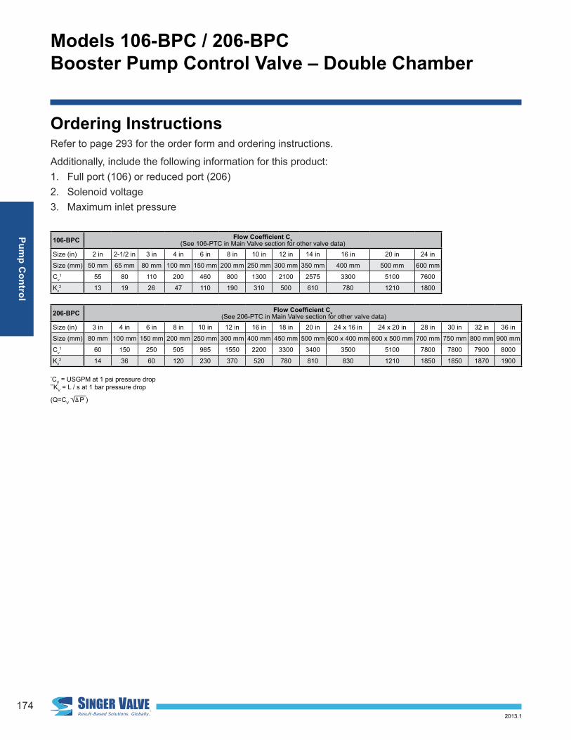
*CV = USGPM at 1 psi pressure drop
**KV = L / s at 1 bar pressure drop
Ordering InstructionsRefer to page 293 for the order form and ordering instructions.
Additionally, include the following information for this product:
1. Full port (106) or reduced port (206)
2. Solenoid voltage
3. Maximum inlet pressure
106-BPCFlow Coeficient C
v
(See 106-PTC in Main Valve section for other valve data)
Size (in) 2 in 2-1/2 in 3 in 4 in 6 in 8 in 10 in 12 in 14 in 16 in 20 in 24 in
Size (mm) 50 mm 65 mm 80 mm 100 mm 150 mm 200 mm 250 mm 300 mm 350 mm 400 mm 500 mm 600 mm
Cv1 55 80 110 200 460 800 1300 2100 2575 3300 5100 7600
Kv2 13 19 26 47 110 190 310 500 610 780 1210 1800
206-BPCFlow Coeficient C
v
(See 206-PTC in Main Valve section for other valve data)
Size (in) 3 in 4 in 6 in 8 in 10 in 12 in 16 in 18 in 20 in 24 x 16 in 24 x 20 in 28 in 30 in 32 in 36 in
Size (mm) 80 mm 100 mm 150 mm 200 mm 250 mm 300 mm 400 mm 450 mm 500 mm 600 x 400 mm 600 x 500 mm 700 mm 750 mm 800 mm 900 mm
Cv1 60 150 250 505 985 1550 2200 3300 3400 3500 5100 7800 7800 7900 8000
Kv2 14 36 60 120 230 370 520 780 810 830 1210 1850 1850 1870 1900
(Q=CV P )

www.singervalve.com175
Models 106-DW / 206-DW
Deep Well Pump Control Valve – Double Chamber
Pu
mp
Co
ntro
l
2013.1
KEY FEATURES• Prevents pump starting and
stopping surges
• No energy loss while pump is running
• Separate opening and closing speed controls
• Discharges initial air/water silt to waste, on well applications.
• Discharges stagnant water at start-up from dormant wells
Product OverviewThe 106-DW and 206-DW deep well pump control valves are installed in a tee between the pump discharge and the check valve.
The valve is normally open, and, on pump start-up, a pilot solenoid is energized to start closing the valve at a rate governed by the closing speed control.
Initially, the valve discharges air, water and sand to waste. The open valve discharges all pump low. As the valve closes slowly, low is transferred to the main line smoothly, increasing the pipeline low without surges. When the valve is fully closed, all pump low is in the pipeline, with no control valve losses.
When shut-down is required, the pilot solenoid on the valve is de-energized to commence opening. The pump is kept running while the valve slowly opens. Increasing proportion of the low is diverted to waste with less passing through the check valve, until all low is diverted through the nearly fully open DW valve. The pipeline check valve closes quietly without surges. When the DW valve is almost fully open, a stem mounted cam triggers the limit switch to stop the pump.
206-DW Angle

176
Models 106-DW / 206-DW
Deep Well Pump Control Valve – Double Chamber
Pu
mp
Co
ntro
l
2013.1
Typical Application
Deep Well Vertical Turbine Pump
Non-slam check valve
Singer model 106-DWDeep Well, Pump Control valve discharges back to sump or to waste (atmosphere)
Pilot pressure sensing line connected to pipeline downstream of header check valve
Provision should be made to drain the small volume of water released with each operation
Isolation valve
Schematic A-7514C
1. Main Valve - 106-PT or 206-PT
2. Closing speed control
3. Strainer - 40 mesh stainless steel screen
4. Isolation Valve
5. Connection to the pipeline system side of header check valve - complete in the ield
6. Exhaust to drain - complete in the ield7. Solenoid Valve - four way, NEMA 4
8. Opening speed control
9. Model X129 Limit Switch Assembly - NEMA 4, SPDT
Schematic Drawing

www.singervalve.com177
Models 106-DW / 206-DW
Deep Well Pump Control Valve – Double Chamber
Pu
mp
Co
ntro
l
2013.1
Standard MaterialsStandard materials for pilot system components are:
• ASTM B-62 bronze or ASTM B-16 brass
• AISI 303 /316 stainless steel trim
Refer to Electronic Control section (SPC product), see page 251, and consult Singer Valve for pump control panel options.
Selection Summary1. The Singer model DW deep well pump control valve is sized to ensure that the pump discharge
pressure is less than the system static pressure when the pump starts; that the main check valve will remain closed and no surges will be generated.
2. From the pump performance curve, determine the pump low when the pressure at the pump discharge is 80% of the static pressure against the check valve. When the pump is discharging at full start-up low, the combined losses of the DW control valve, the piping and the discharge losses must be less than 80% of the static pressure.
3. For pump control other than deep well applications - by-pass control - the discharge from the DW control valve can be returned to the wet well, tank or even the pump suction header. Providing there is suficient static differential pressure (e.g., 70 to 80% of the pumping differential pressure) the DW control valve should be considered preferable to a BPC, in-line booster pump control valve because of reduced sizing and operating beneits.
4. Refer to the 106 and 206 performance curves, page 284, angle or globe style (straight lines) (see Technical & Sizing Information section, page 282) and select the smallest size with the pressure drop that is acceptable. Bulletins 106-PT(C) and 206-PT(C) (see Main Valves section, page 34) provide / speciications and details of construction of the main valves. Standard coniguration pro-vides for NEMA 4 watertight enclosures for the Honeywell model OP-AR, SPDT limit switch and the ASCO solenoid with 120 VAC / 60 Hz (or 220 VAC / 50 Hz or 240 VAC / 60 Hz) coil. For other electrical service or higher pressure ratings consult with Singer Valve. A manual override is avail-able upon request. Other functions may be combined with DW valves, e.g. model 106-DW-RPS, pump control with pressure sustaining feature.

178
Models 106-DW / 206-DW
Deep Well Pump Control Valve – Double Chamber
Pu
mp
Co
ntro
l
2013.1
Speciications• The valve shall be a Singer Valve model 106-DW / 206-DW, size “_____”, ANSI Class 150 (ANSI
300, ANSI langes drilled to ISO PN 10 / 16/ 25 or 40) pressure rating / lange standard, globe (angle), style valve. Solenoid Valve shall be four-way de-energized to open valve, with a 120 VAC / 60 Hz (220 VAC / 50 Hz or 240 VAC / 60 Hz) solenoid coil. Assembly shall be according to Schematic A-7514C.
• The valve shall be normally open. On pump start-up, a pilot solenoid is energized to close the valve, at a rate governed by the closing speed control. Separate low control valves and a double chamber design will allow opening and closing speeds to be adjusted independently. When the solenoid is de-energized the valve slowly opens while the pump continues to run. When the valve is almost fully open and all low has been diverted as a result of the pipeline check valve closing, a stem-mounted cam triggers the limit switch to stop the pump.
• Refer to Main Valve section, page 34, 106-PT (or 206-PT) for detailed information pertaining to valve sizes and materials, selection criteria and speciications.
• Refer to Pilot and Accessories section, page 277, Micrometer Flow Control Valves for detailed information pertaining to materials and speciications.
• Solenoid speciication information is available from Singer Valve only at this time.
Ordering InstructionsRefer to page 293 for the order form and ordering instructions.
Additionally, include the following information for this product:
1. Full port (106) or reduced port (206)
2. Solenoid voltage
3. Maximum inlet pressure

www.singervalve.com179
Models 106-DW / 206-DW
Deep Well Pump Control Valve – Double Chamber
Pu
mp
Co
ntro
l
2013.1
*CV = USGPM at 1 psi pressure drop
**KV = L / s at 1 bar pressure drop
(Q=CV P )
106-DWFlow Coeficient C
v
(See 106-PT in Main Valve section for other valve data)
Size (inches) 2 in 2-1/2 in 3 in 4 in
Size ( mm) 50 mm 65 mm 80 mm 100 mm
Cv1 - Globe 55 80 110 200
Kv2 - Globe 13 19 26 47
Cv1 - Angle 61 90 135 230
Kv2 - Angle 15 21 32 55
206-DWFlow Coeficient C
v
(See 206-PT in Main Valve section for other valve data)
Size (inches) 4 in 6 in 8 in 10 in
Size ( mm) 100 mm 150 mm 200 mm 250 mm
Cv1 - Globe 150 250 505 985
Kv2 - Globe 36 60 120 230
Cv1 - Angle 150 250 580 -
Kv2 - Angle 36 60 138 -
106-DWFlow Coeficient C
v
(See 106-PT in Main Valve section for other valve data)
Size (inches) 6 in 8 in 10 in 12 in 14 in 16 in 20 in 24 in
Size ( mm) 150 mm 200 mm 250 mm 300 mm 350 mm 400 mm 50 mm 600 mm
Cv1 - Globe 460 800 1300 2100 2575 3300 5100 7600
Kv2 - Globe 110 190 310 500 610 780 1210 1800
Cv1 - Angle 520 950 1400 2400 - 3000 - -
Kv2 - Angle 123 225 332 570 - 710 - -
206-DWFlow Coeficient C
v
(See 206-PT in Main Valve section for other valve data)
Size (inches) 12 in 16 in 18 in 20 in 24 x 16 in 24 x 20 in 28 in 30 in 32 in 36 in
Size ( mm) 300 mm 400 mm 450 mm 500 mm 600 x 400 mm 600 x 500 mm 700 mm 750 mm 800 mm 900 mm
Cv1 - Globe 1550 2200 3300 3400 3500 5100 7800 7800 7900 8000
Kv2 - Globe 370 520 780 810 830 1210 1850 1850 1870 1900
Cv1 - Angle - - - - - - - - - -
Kv2 - Angle - - - - - - - - - -

180
Models 106-HC / 206-HC
Hydraulic Check Valve
Pu
mp
Co
ntro
l
2013.1
Singer Model 106-RPS
Reservoir Tank
Booster Pump
Singer Model 106-HC
KEY FEATURES• Drip-tight seat
• Independently adjustable opening and closing speed controls
Product OverviewThe 106-HC and 206-HC hydraulic check valves are based on the 106-PG or 206-PG main valve. The valve functions as a two position valve - either fully open or fully closed.
The HC allows one way low only. Under normal forward low, the valve opens as the higher inlet pressure lifts the inner valve assembly and the luid in the upper chamber is discharged to the lower pressure, downstream side of the valve.
When pressure is reversed, the now higher downstream pressure is applied to the upper operating chamber as low reversal occurs. The diaphragm / inner valve assembly moves down and the valve closes tightly.
Typical ApplicationPrimary use as a simple, effective way to start and stop pumps without surges. No electrical supply or interconnections required. Power failure shutdown is the same as normal operation. Best used when the pump is electric motor driven and has positive suction head. A system relief valve is recommended for sizes 6 in / 150 mm and larger or when velocities exceed 6 ft/s / 2 m/s.
Important Note:
To provide smooth “non-slam” shutdown when the pump stops, the low reverses for a short period. Install with forward low over the seat. Most pumps and motors can accept reverse rotation (consult with pump manufacturer before selecting hydraulic check valves). Engine drivers will be damaged by reverse rotation - include a non-reverse clutch or similar device. No other check or foot valves should be installed to prevent reverse low. When there is suction lift on the pump inlet, a separate form of priming is necessary. See BPC or DW valves for alternate methods of starting or stopping lows exceeding 13 f/s / 4 m / s).
206-HC Globe

www.singervalve.com181
Models 106-HC / 206-HC
Hydraulic Check Valve
Pu
mp
Co
ntro
l
2013.1
1. Main Valve 106-PG or 206-PG - “Flow Over Seat”
2. Closing Speed Control
3. Opening Speed Control
4. Swing Check Valve - opening
5. Swing Check Valve - closing
The standard valve is normally installed in a horizontal pipeline with the stem oriented vertically up. Conirm other orientations before ordering.
Type Pressure Rating*
300 SCR. 200 psi / 13.8 bar
150 FLG. 200 psi / 13.8 bar
300 FLG. 300 psi / 20.7 bar
* Pressure ratings are limited by the choice of pilot
components.
Schematic A-0422D
Schematic Drawing
Standard MaterialsStandard materials for pilot system components are:
• ASTM B-62 bronze or ASTM B-16 brass
• AISI 303 / 316 stainless steel trim
Speciications• The valve shall be a Singer Valve model 106-HC / 206-HC, size “_____”, ANSI Class 150 (ANSI
300, ANSI langes drilled to ISO PN 10 / 16 / 25 or 40) pressure rating / lange standard, globe (angle), style valve. The Opening Speed Control shall be adjusted in the ield to allow for slow opening. Closing speed should be ield adjusted to permit slow closing after allowing surges through the valve and back to the source preventing damage (check with pump supplier to determine if backlow through pump is acceptable). Assembly shall be according to Schematic A-0422D.
• The valve shall open for normal direction of low and close to prevent reverse low. Opening and closing speeds shall be individually adjusted to prevent surges. The valve shall be installed allowing for low over the seat (low is in the opposite direction through the valve as compared to other standard function categories).
• Refer to Main Valve section, page 11, 106-PG / 206-PG for detailed information pertaining to valve sizes and materials, selection criteria and speciications.

182
Models 106-HC / 206-HC
Hydraulic Check Valve
Pu
mp
Co
ntro
l
2013.1
Selection Summary:1. Generally select size to minimize losses during normal forward low. 2. Use the performance curves and sizing bulletin (see Technical and Sizing Information Section 275)
to check the pressure drop across the valve at normal low rate. Use the same performance curves for low over the seat or low under the seat.
3. Check the maximum operating pressure. The pilot system limits the rating.
4. Standard construction provides: 200 psi / 13.8 bar
5. Rating for ANSI 150 langed and NPT screwed ends; 300 psi / 20.7 bar rating for ANSI 300 langed. Consult Singer Valve for applications requiring higher pressure ratings.
Ordering InstructionsRefer to page 293 for the order form and ordering instructions.
Additionally, include the following information for this product:
• Full port (106) or reduced port (206)
106-HCFlow Capacity
(See 106-PG in Main Valve section for other valve data)
Size (inches) 1/2 in 3/4 in 1 in 1-1/4 in 1-1/2 in 2 in 2-1/2 in 3 in 4 in
Size (mm) 15 mm 19 mm 25 mm 32 mm 40 mm 50 mm 65 mm 80 mm 100 mm
Max. Continuous (USGPM) 12 19 49 93 125 210 300 460 800
Max. Continuous (L/s) 0.8 1 3 6 8 13 19 29 50
206-HCFlow Capacity
(See 206-PG in Main Valve section for other valve data)
Size (inches) 3 in 4 in 6 in 8 in 10 in 12 in 16 in 18 in 20 in
Size (mm) 80 mm 100 mm 150 mm 200 mm 250 mm 300 mm 400 mm 450 mm 500 mm
Max. Continuous (USGPM) 300 580 1025 2300 4100 6400 9230 16500 16500
Max. Continuous (L/s) 19 37 65 145 260 404 582 1040 1040
106-HCFlow Capacity
(See 106-PG in Main Valve section for other valve data)
Size (inches) 6 in 8 in 10 in 12 in 14 in 16 in 20 in 24 in 36 in
Size (mm) 150 mm 200 mm 250 mm 300 mm 350 mm 400 mm 500 mm 600 mm 900 mm
Max. Continuous (USGPM) 1800 3100 4900 7000 8500 11000 17500 25000 55470
Max. Continuous (L/s) 114 196 309 442 536 694 1104 1577 3500
206-HCFlow Capacity
(See 206-PG in Main Valve section for other valve data)
Size (inches) 24 x 16 in 24 x 20 in 28 in 30 in 32 in 36 in 40 in
Size (mm) 600 x 400 mm 600 x 500 mm 700 mm 750 mm 800 mm 900 mm 1000 mm
Max. Continuous (USGPM) 16500 21700 33600 33650 33700 33800 62000
Max. Continuous (L/s) 1040 1370 2120 2123 2126 2132 3912