models and control for force/torque sensors in robotics
TRANSCRIPT

I M P A R T M L N T O P MIC H A N K Al LNCWNLHRINC.
Linköping Studies in Science and TechnologyLicentiate Thesis No. 317
Models And Controlfor
Force/Torque Sensors in Robotics
Gert Johansson
Assembly Technology
LiU-Tek-Lic-1^92:09
1992-04-27
Institute of Technology. Dcpt of Mech Lug. S-5M N3 Linköping. Sweden
Linköping Studies in Science and Technology-Licentiate Thesis No. 317
Models And Controlfor
Force/Torque Sensors in Robotics
Gert Johansson
Assembly Technology
LiU-Tek-Lic-1992:09ISBN 91-7870-895-8
ISSN 0280-7971
1992-04-27

<3^ • • ^&\a
f
Avdelning, Institution, FakultetDivision, Department, Faculty
Institute of TechnologyDepartment of Mechanical EngineeringDiv. of Assembly Technology581 83 Linköping
ISBN: 91-7870-895-8issN: 0280-7971
T: LiU-Tek-Lic-1992:09Upplagans storlek: i cgNumber of copies:Datum:Date: 1992-04-27
Projekt:Project:
Titel:Title:
Författare;Author:
Models and Control for Force/Torque Sensors in Robotics
Gert Johansson
Uppdragsgivare:Commissioned by:
Dnr:Call no:
Rapporttyp:Kind of report:
| ~ | Examensarbete Final project
[~j Delrappon/Progress report1 1 Reserapport/Travel report
f j Slutrapport/Final report
Q Övrig rapport/Other kind of report
Rapportsprlk:Language:
1 1 Svenska/Swedi
[>) Engelska/ Engli
D
Sammanfattning (högst 150 ord):Abstract (150 words):
One of the important problems in automatic assembly is the relative positioning accuracy be-tween the i^irts in the assembly process. Inaccurate positions can hinder succesful assembly.
This thesis presents a solution based on active feedback of force/torque data from a wristmounted sensor. A task independent control algorithm transforms force/torque input to relevantmotion of the end effector. The transform ;tion, called the sensor model, is specified by e.g.desired forces, compliance and stoppir . ji sria. An algorithm and a calibration sequence forthe compensation of end effector gravi * T :S are developed. To allow necessary modificationsand expansions for the integration of n s, an open and general control system architectureis proposed. The architecture is bas . n . computer workstation and pipelined Transputers.
The thesis is divided into two parts, r nt t is a summary and introduction of the authors work.The second part is an appendix inch, r i three internationally published papers:
N y c k e l o r d ( h ö g s ! 8 ) .K e y w o r d s ( m a x . 8 ) : force, torque, sens< del, robot controller, gravity compensation, automatic assembly
- *+ •
AbstractOne of the important problems in automatic assembly is the relative positioningaccuracy between the parts in the assembly process. Inaccurate positions causelarge insertion forces, wear and might damage the parts. They can also com-pletely disable the assembly process. A solution to this problem is to detectthe positioning error and to make a relevant adjustment of the position or path.
This thesis presents a solution based on active feedback of force/torque datafrom a wrist mounted sensor. A task independent control algorithm has beenrealized through a sensor model concept. The sensor model includes an algo-rithm that transforms force/torque input to relevant motion of the end effector.The transformation is specified by a set of parameters e.g. desired forces, com-pliance and stopping criteria. The problem with gravity forces for varying endeffector orientation is compensated by an algorithm, divided into three com-plexity levels. The compensation method includes a calibration sequence toensure valid end effector properties to be used in the algorithm. A problemwith available robot technology is bad integration possibilities for external sen-sors. To allow necessary modifications and expansions, an open and generalcontrol system architecture is proposed. The architecture is based on a comput-er workstation and Transputers in pipeline for the robot specific operations.
The thesis is divided into two parts, the first is a summary and introductionof the authors work. The second part is an appendix including three interna-tionally published papers:
1. General Parametric Sensor Model with ExternalCommunication Possibilities
2. Towards Common Infrastructure for AdvancedManufacturing Control Systems
3. An Efficient Mass Compensation Method for Force/TorqueControl in Robotics

AcknowledgementsThe work of writing a thesis is mostly a one man job. However, without thesupport from several key persons this thesis would not have been written.
I would like to start my acknowledgements with a thank you to my parents,Lennart and Kerstin Johansson, who always have been encouraging me withoutpushing. I would also like to thank my wife for her patience with a sometimesslightly disordered husband, thinking of his work.
My gratitude to my supervisors, professor Nils Mårtensson and professorChrister Johansson, they have both been supporting my research and takengreat interest in it.
I would like to express my appreciation to Lars Wennström. who introducedme to this most exiting area of research.
The former STU, nowadays NUTEK, has been a valuable support. They havebeen funding the research projects I have been working in.
Last but not least. I would like to thank my colleagues at VerkstadstekniskaMonteringssystem for interesting discussions and good friendship. A specialrecognition to Bertil Söderqvist who have tried to teach me how to use theEnglish language in some of my work and Roland Almgren for good collabora-tion with the controller concept.

Table of contentsAbstract 3
Acknowledgements 5
Table of contents 7
Figures 9
1. Introduction 111.1 The flexibility problem 111.2 Solving a part of the flexibility problem 12
2. Problem description 14
3. Thesis 173.1 Limitations 17
4. Review of the literature 18
5. The approach to a solution, introduction of the workand papers 22
6. The sensor model concept 246.1 Task independent control 246.2 Task specification with parameters 25
7. Proposal to new robot controller architecture 277.1 A general computer as platform 277.2 Transputer architecture 28
8. Compensating gravity forces 318.1 End effector mass and orientation 318.2 Gravitation and acceleration 328.3 Three different complexity levels 34
9. Practical tests 369.1 Peg into hole insertion 369.2 Mass compensation 389.3 Following a template 389.4 Locating boiler connection holes 39
10. Results and conclusions 42
References 44
Appendix 51General Parametric Sensor Model with External Communication
Possibilities 53Towards Common Infrastructure for Advanced Manufacturing
Control Systems 63An Efficient Mass Compensation Method for ForccTorquc Control
in Robotics 75

FiguresFigure 1. Experimental setup for the force/torque guided insertion of
a peg into a chamfered hole 14Figure 2. a) tight tolerance and bad accuracy causes contact forces.
b) Loose tolerances allows insertion without contact forces ISFigure 3. Design for assembly has great impact. The chamfer can guide
the peg into the hole 15Figure 4. The drawer gets stuck (Jamming) because of unequal
applied forces 16Figure S. Spring and damper in parallel 18Figure 6. Assembly forces causing wrist torques. T = F x D !9Figure 7. Hybrid control based on position in x-direction and forces in
y- and znJirection 20Figure 8. Modification of Whitneys four state description of the
insertion operation 22Figure 9. The peg is not correctly inserted although the force
requirements are fulfilled 24Figure 10. a) Force and torque frames, dotted lines indicating desued
force or torque intervals, b) Sensor-fixed coordinate frame 25Figure 11. A general computer as a robot controller 28Figure 12. Hardware and software configuration for distributed and
parallel processes of robot motion control 29Figure 13. Linear interpolated point to point control. Intermediate
positions reached every 12 milliseconds 29Figure 14. Memory layout of the dual ported memory. [Lindholm. 1990J 30Figure 15. Varying gravity forces (MG) caused by different orientations. 31Figure 16. The mass of the end effector and a part of the sensor causes
gravity forces, mg. (the shaded parts) 32Figure 17. Acceleration vector (A) consisting of dynamic acceleration (Ad)
and gravitation (G). [appendix C] 33Figure 18. Newtons law of action and reaction. Fe in the direction of
the end effector acceleration . Fs is the reaction force acting inthe opposite direction on the sensor. The gravity force of the endeffector (MG) and the reaction force (FGs) detected by the sensorare equal in direction and magnitude 34
Figure 19. Structure of the sensor model application program 36Figure 20. Test setup for peg into hole insertion 37Figure 21. A special designed tool for template following. Two sensing
tips in contact with the surfaces causes forces and torques tomaintain the position and direction along the template 39
Figure 22. Test setup for the locating of boiler connections holes witha conic tool 40

1. Introduction
1.1 The flexibility problem
Today companies have to compete hard to survive and get market shares. Sev-eral factors have to be improved to achieve good profit and the ability to devel-op new competitive products. Some important factors are product quality anddesign, adaptation of the products to simplify manufacturing (DFM). lean pro-duction with a minimum of buffers, short setup times for different variantsof the product and the factory organization. These factors can of course havevarious impact in different cases. A factor where improvements always arepossible and can give a direct result is the production. The production has tobe efficient and flexible to meet the customers requirements of variants andnew models. As lifetime cycles for industrial products gets shorter. FlexibleManufacturing Systems (FMS) become more advantageous. The basic idea offlexible production is that the equipment and staff shall produce products in-stead of using the time for reconfiguring the factory or the individual machines.If the equipment and factory organization are prepared for the change of varia-nts and new models or products, a minimum of exchange time will be needed.Manufacturing systems can be flexible in a technical sense, but also in econom-ical terms. A technically flexible equipment is usually recognized by short ex-change time for different products and can easily be modified for new prod-ucts. In economical terms, a rigid system can also be flexible. If the systemis very cheap and can be easily replaced or rebuilt at a low cost when it istime to change for a new model it can be a better choice than flexible equip-ment which usually is more expensive. Long series and few variants are tradi-tional requirements for rigid systems to be cost effective.
This thesis will only deal with the technical aspects of flexible equipment. Thatis technical solutions that increases the possibilities to make adaptations tonew products or new conditions. The industrial robot is a good example ofa technically flexible equipment which can be used in many different applica-tions. However, robot adaptations to new products requires new programs andperhaps new end effectors and environmental equipment. Programming a ro-bot is often time consuming and on-line teaching of robots when stopping pro-duction is seldom acceptable. Off-line programming is more advantageoussince the complete program structure can be built outside the robot withoutstopping the production. Still, most positions in the robot program must betaught in the real robot environment, which causes interrupts in production.The first period in the history of a new production line usually requires rrajoradaptations and adjustments to eliminate error sources. The adjustment periodmight often be long and costly. At the same time the production rate will belower than the nominal. If the product mix is very rich of variants, these adjust-ment periods might be quite considerable.

1.2 Solving a part of the flexibility problem
To some extent, active sensor support can solve the problem of expensive andless productive adjustment periods. Examining robotic assembly installationsshows that a great deal of the problems are focused to the contact motions.The problem increases with narrow tolerances and causes excessive forceswhen the relative mating positions are inaccurate. If the tolerances are tighterthan the repositioning accuracy of the robot, there will always be mating forcesof varying magnitude and direction. The assembly forces might damage thepans and cause high wear on fixtures and end effectors. Another error sourceis the fixturing of the base part. Tolerances and wear of the fixtures causesmore positioning inaccuracy outside the robot structure. Wear of fixtures andend effectors, thermal effects etcrequires adjustments of robot positions to bedone more or less regularly, it might also cause stop in production. Anotherproblem source is defective pans that can disturb the assembly process. Theseproblems might decrease the possibility of unmanned production, which other-wise could be profitably. A sample solution can be to use vision for identifyingand locating objects to be gripped, instead of arranging specific feeders andfixtures. Force/torque sensing can control the mating of parts to avoid largeforces and wear [Johansson. 19S8]. It can also detect large forces resultingfrom defective parts. The drawback is that when a traditional production lineis adjusted and working properly, it is faster than using sensors for all criticaloperations. This statement is of course only valid if it is possible to performsensor-less production. A conclusion is that systems with sensors can not com-pete with sensor-less systems in long series production, only for short serieswhere fixturing costs etc will be too high. The concept outlined here is to usesensors (read force'torque sensors) mainly for programming, supervision andadjustments. The benefit is that the comparatively slow active sensor controlis used only when it is necessary. Ser.>urs are then used to adapt theoreticalpositions to the real ones, the first time a new robot program is executed.Thereafter sensors are used mainly for supervision and to correct operationsthat are unsuccessful. The performance of this kind of system is equal to con-ventional sensor-less ones, since sensors are just supervising and does not slowdown the execution of the robot program. The sensor based system has theadvantage of being better during the adjustment period and for detecting andcorrecting errors.
As outlined, sensors can give a good contribution to flexibility in FMS. Gener-ally, a complex and advanced sensor can give more nuanced information aboutthe actual state, on the other hand it is often demanding to extract this informa-tion. Therefore it is important to categorize the information and transform itinto a format, easy to handle. The ultimate goal must of course be to achievereal time performance for advanced senior control, allowing them to be activein every critical operation. This coal must be seen in a longer perspective, butwith a relevant control system architecture with high computational power andhigher sampling rates, this might be possible.
This thesis is based on three papers dealing with different aspects of sensorcontrol of industrial robots The research work has concerned a "sensor model

concept" for a force/torque sensor, requirements and architectures for robotcontrollers and an algorithm to make force/torque sensor? more independentof orientation changes with respect to end effector mass.
13

2. Problem descriptionThe presented work has been carried out in the area of automated assembly.Great emphasis is put on the flexible assembly systems (FAS), where the in-dustrial robot is studied as it is a flexible and important piece of equipment.Other related projects at the department are concerning: ecciomy in assemblysystems, the design of assembly systems, design for assembly, product model-ling, robotic assembly program generation, robot vision, programmable com-pliance, and this project concerning sensor models and robot control The focushas been set to the assembly process where the contact based motion has beenof major interest The real problems in assembly becomes obvious when con-tact is reached. Assuming that no defective parts exist, there is theoreticallyno problem with assembly processes as long as positioning and path accuracyare absolute. In practice though, there will always be minor position and orien-tation errors, sec figure 1. These errors will cause forces and torques when
Figure I. Experimental letup for the force/torque guided insertion of apet into a chamfered hole
parts are being assembled If the assembly forces are large, the parts can bedamaged or the the insertion might be impossible. Just refining the robot accu-racy is no! enough to solve the assembly problem. The rest of the assemblystation docs also include inaccuracies: fixture and feeder positions, inaccuratecripptrs etc. Hven temperature changes can cause varying positions The re-sulting forces are functions of the tolerances of the assembled parts and theposition error, see figure 2.
Another factor which is verv important for the assembly process is the designof all parts Compare the hole and shaft in figure .V The chamfer of the hole

a)
Figure 2. a) tight tolerance and bad accuracy causes contact forces.b> Loose tolerances allows insertion without contact forces.
Figure _*. Design for assembly has great impact. The chamfer can guidethe pes into the hole.
and or the shaft is a good example of design where the assembly process hasbeen considered. Assuming some compliance in the system, it is obvious thatthe chamfer can guide the shaft into the hole even with some lateral errors.Without the chamfer this is impossible, the position has to be perfect for adirect fit
If lateral errors causes forces that can damaee the parts and even make inser-tion impossible, orientation errors might cause jamming and wedging. Jam-ming is a phenomenon, similar to closing a drawer with to much force appliednn cither left or right side The drawer gets stuck as it is tilted slightly andgets into a diagonal two point contact, sec figure 4. Wedging is principallythe same as jamming but more ill conditioned. It occurs with specific ratiosbetween diameter, lencth. tolerance, friction and elasticity. Wcdcine is charac-

Figure 4. The drawer gets stuck (jamming) because of unequal appliedforces.
terized by the difficulty of pulling the object back. The parts does often getdamaged when they are removed.
The flexibility of man can not be reached with automatic methods (today),but automatic assembly has the advantage in the long run with good and evenquality. Several factors affect the possibility for automatic assembly. A feware mentioned above, like: position and orientation accuracy, tolerances, de-sign for assembly, etc. All these aspects have to be considered in order to makereal improvements to automatic assembly. Tn this thesis the industrial robotis equipped with a force/torque sensor to control the contact forces and therebythe relative positions of the assembled objects. This is one step towards moreflexible automatic assembly.
16

3. ThesisThe basic problem in automatic assembly is the positioning accuracy. Force/torque control of industrial robots in contact operations has the ability to reduceposition and orientatior errors. A sensor model concept will simplify the useof force/torque sensors in robotic applications and an advanced robot control-ler will make it time and cost effective to develop such solutions.
3.1 Limitations
This work is focused on sensor based control of industrial robots. Other solu-tions to automatic assembly besides industrial robots have not been considered.The purpose of the work has been to improve the robot capabilities to manageassembly in a more efficient way. The force/torque feedback regulation hasbeen considered in cartesian space and did not concern motor regulation injoint space.
17
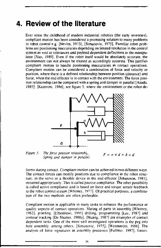
4. Review of the literatureEver since the childhood of modern industrial robotics (the early seventies),compliant motion has been considered a promising solution to many problemsin robot control e.g. [Nevins, 1973], [Simunovic, 1975]. Familiar robot prob-lems are positioning inaccuracies depending on limited resolution in the controlsystem as well as tolerances and payload dependent deflections in the manipu-lator [Yao, 1989]. Even if the robot itself would be absolutely accurate, theenvironment can not always be treated as accordingly accurate. This justifiescompliant motion to handle positioning inaccuracies in contact operations.Compliant motion can be considered a combination of force and velocity orposition, where there is a defined relationship between position (distance) andforce, when the end effector is in contact with the environment. The force posi-tion relationship can be compared with a spring and damper in parallel [Asada,1985], [Kazeroni, 1986], see figure 5, where the environment or the robot de-
Figure 5. The force position relationship,Spring and damper in parallel.
F=o*d+dxd
forms during contact. Compliant motion can be achieved in two different ways.The contact forces can modify positions due to compliance in the robot struc-ture, in the servo or a flexible device in the end effector [Johansson, 1981],mounted appropriately. This is called passive compliance. The other possibilityis called active compliance and is based on force and torque sensor feedbackto the robot control system.[Whitney, 1977]. Of practical purposes, a combina-tion of the two methods are often preferable.
Compliant motion is applicable in many tasks to enhance the performance orquality aspects of contact operations. Mating of parts in assembly [Whitney,1982], grinding, [Elbestrawi, 1991 j drilling, programming [Lee, 1987] andcontour tracking [De Shutter, 1988a], [Huang, 1987] are examples of contactdependent tasks. One of the most well investigated operations is the peg intohole assembly, among others, (Simunovic, 1975], [Wennström, 1988]. Theanalysis of force signatures in assembly processes [Fullmer, 1987], forces,

torques and motions in four different stages of the assembly operation [Whit-ney, 1982] gives good basic knowledge when designing a compliant unit forassembly (Remote Center Compliance, RCC)[Drake, 1977], [Ericsson, 1979]or the computer algorithms for active force feedback compliance. Early imple-mentations [Nevins, 1973], [Whitney, 1977] of force feedback consists of adesired trajectory which is modified by force feedback and a task dependentforce control law. With this method, programming the task and designing theforce feedback law is closely related, which might be time consuming and diffi-cult for the average robot programmer.
A slightly different approach to enhance performance was investigated by [VanBrussel, 1978]. The solution was to configure the manipulator in such a waythat each joint correlated to cartesian coordinate axes. With this configurationthe forces in each translational joint was equal to the assembly forces. Therelationship between measured force and the desired correction was simpleand could be directly fed back to the respective joint controller. This did notapply exactly to the rotational joints because the lateral forces also causedtorques see figure 6. The problem could be handled by specifying great stif-
Figure 6. Assembly forces causing wrist torques. T = F x D
fness in the wrist, causing lateral errors to be eliminated first. The benefit ofthis concept was twofold: good control performance (fast) and it was easy tospecify the assembly strategy.
The next development of compliant motion specification technique, oftencalled: "Hybrid force/position control" was developed by [Raibert, 1981], [Ma-son, 1981] and [Zhang, 1985]. What they had in common was the separationof force control specification from the control law implementation, makingit easier for the user. All contact tasks can be divided into directions controlledby forces and directions controlled by positions, see figure 7. This means thata force controlled direction is in contact with some kind of surface, and there-fore not free to move in that direction. The opposite is relevant for position
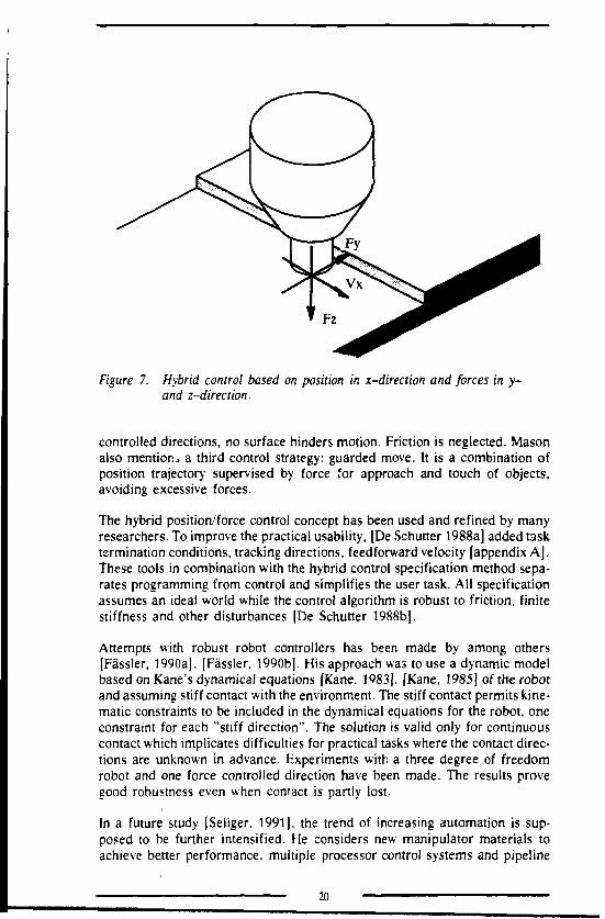
Figure 7. Hybrid control based on position in x-direction and forces in y-and z-direaion.
controlled directions, no surface hinders motion. Friction is neglected. Masonalso mention., a third control strategy: guarded move. It is a combination ofposition trajectory supervised by force for approach and touch of objects,avoiding excessive forces.
The hybrid position/force control concept has been used and refined by manyresearchers. To improve the practical usability, [De Schutter 1988a] added tasktermination conditions, tracking directions, feedforward velocity [appendix A].These tools in combination with the hybrid control specification method sepa-rates programming from control and simplifies the user task. All specificationassumes an ideal world while the control algorithm is robust to friction, finitestiffness and other disturbances [De Schutter 1988b].
Attempts with robust robot controllers has been made by among others[Fässler, 1990a], [Fässler, 1990b]. His approach was to use a dynamic modelbased on Kane's dynamical equations [Kane, 1983], [Kane, 1985] of the robotand assuming stiff contact with the environment. The stiff contact permits kine-matic constraints to be included in the dynamical equations for the robot, oneconstraint for each "stiff direction". The solution is valid only for continuouscontact which implicates difficulties for practical tasks where the contact direc-tions are unknown in advance. Experiments with a three degree of freedomrobot and one force controlled direction have been made. The results provegood robustness even when contact is partly lost.
In a future study [Seliger, 1991]. the trend of increasing automation is sup-posed to be further intensified. He considers new manipulator materials toachieve better performance, multiple processor control systems and pipeline
20
concept [appendix B] to improve updating frequency, as the most importantfields in robotics research. Controlling compliant manipulators made by e.g.reinforced plastic, requires dynamical models of the manipulator. Severalmethods for dynamic control of manipulators have been studied [Hollerbach,1980], [Silver, 1980], [Yang, 1986] are just a few examples. The inertial fea-tures of a dynamically controlled robot are very irr.nortant for the resultingprecision. A promising method to achieve those parameters is to use forceand/or torque sensing to "calibrate" the inertia! properties of the manipulatorstructure [An, 1985], [Baucent, 1989], [Mukerjce, 1989]. An et al estimatedinertial information of robot links by measuring of joint torques while the ma-nipulator was moving. An algorithm based on Newton Euler equations calcu-lated mass, center of gravity and the moments of inertia for each link. Mukerjeapplied full force torque sensing in each joint. This allows complete inertialinformation for each link and reduces (eliminates) propagation errors acrossthe manipulator.
The robot research is very often performed (applied) on special designed re-search robots with equally designed controller. The major reason for this isthe lack of commercial robots with open controller architectures and generalprogramming languages. The requirements on robot programming languagesdiffers in a wide range, from factory floor operators to robot researchers atuniversities and research centra's. A common viewpoint is that programminglanguages for robots should support the requirements for the most advancedusers [Lozano-Peréz, 1982], [Taylor, 1982]. It is then possible to implementappropriate progrimming interfaces in the robot bnguage itself. An interestingway to implement these ideas is to use a common programming language likeC or Pascal and make software modules for the robot specific operations [Hay-ward, 1986], [Zebra],
21

5. The approach to a solution, intro-duction of the work and papers
To solve the problem of automatic assembly, all the factors mentioned in theproblem description chapter have to be improved. This work is however fo-cused on one of them, the problem of positioning inaccuracy. By using force/torque sensor feedback in contact based processes, this problem can be solved.
When the author first got in contact with force/torque controlled robots, theapproach to solving the adaptivity problem for industrial robots was accordingto a modification of Whitneys four state description of the insertion phase[Whitney, 1982], see figure 8. The force/torque control was carried out in four
1 2,3Figure 8. Modification of Whitneys four state description of the insertion
operation
different algorithms, one for each state. Briefly described follows the algo-rithms used in each step:
* state 0, no contact, search in approach direction for verticalforce.
* state 1: one point contact, compensate for horizontal forces,move in the approach direction, repeat until state 2 occurs.
* state 2 and 3: two point contact, compensate for horizontalforces and horizontal torques, move in the approach direction,repeat until force limit for state four is reached.
' state 4: the final position is reached when the force in the op-posite direction of the approach vector increases to a prede-fined limit.

For a more detailed description, refer to [Lundberg, 1986). After studying thiskind of strategy, it became evident that this approach would be very demandingin analysis and algorithm design. Practically all plausible contact based taskswould have to be analyzed and a control algorithm be designed. A more generaland task independent algorithm would be a solution to this problem.
23

6. The sensor model conceptThe author's work started with a deeper analysis of the insertion problem,which showed that a possible solution was a combination of state one and statetwo/three ns described in the previous chapter. The overall algorithm to elimi-nate horizontal forces and horizontal torques, is valid from state 0 throughstate 3. The desire in state four, to reach a vertical contact force, can aisobe included in the "overall" algorithm. A logical consequence of the desireto reach a vertical contact force would be a robot motion in the opposite direc-tion of the force. This force dependent motion can replace the constant motionin the old algorithm. When the desired force is reached and no other forcesor torques are at hand, the goal position is probably reached as illustrated infigure 8, state 4. Unfortunately, this is no proof for the goal position beingreached. An equivalent force will occur if the peg remains standing on theedge of the hole, see figure 9. To overcome the weakness of this simple stop-
Figure 9. The peg is not inserted although the force requirements for stoppingare fulfilled.
ping criteria, some more requirements can be added [appendix A]. In theabove example, adding a distance requirement to the force/torque criteria willprove that the goal position is reached. Adding a timer can stop an unsuccessfulinsertion after a predefined elapsed time, indicating e.g. what happened infieure 9.
6.1 Task independent control
The analysis of the insertion problem indicated that a simpler and more generalforce/torque-based description was possible. In the beginning of the 1980'svan Brussel conducted research on an insertion machine The machine con-sisted of a cartesian arm and a 2 dof (degree of freedom) wrist. The jointswere controlled with feedback of forces (arm) and torques (wrist) in a digitalregulator [van Brussel, 1978]. The regulator principle for keeping forces neardesired values, seemed very interesting and suitable for the force/torque-based
24
algorithm outlined above. Transforming the motor regulation principle intohand space and a force-distance regulation relative to the wrist mounted sensorframe axes, gives independence of the manipulator design. Since the robotis controlled in base frame coordinates, wrist related coordinates from the reg-ulation has to be translated into the base frame. The ABB robots were facili-tated with a reltool function [ABB, 1986] permitting movements relative tothe robot wrist. Because of limited access possibilities from peripheral "omput-ers, a new control package was implemented on an Apollo workstation, basedon The ARAP (Asea Robot Applicat.v . Protocol) (by that time Asea, laterABB) [Johansson, 1989]. The complete robot programs were now running onthe Apollo workstation, eliminating logic and programs to be divided into twocomputers. A new "reltool" function was implemented in the Apollo basedcontrol package to maintain control relative to the wrist position, necessaryfor force/torque control. Input to the "reltool" function is the current gripperpose (position and orientation) and the incremental movement relative to thecurrent pose.
6.2 Task specification with parameters
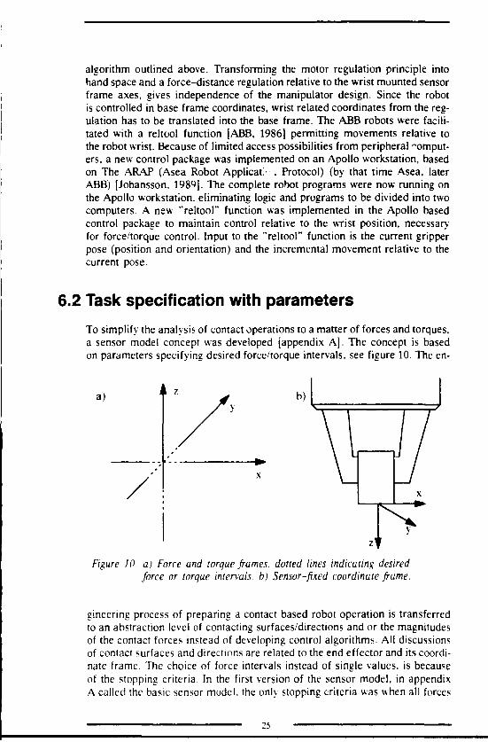
To simplify the analysis of contact operations to a matter of forces and torques,a sensor model concept was developed (appendix A]. The concept is basedon parameters specifying desired force/torque intervals, see figure 10. The en-
a) b)
Figure 10. a) Force and torque frames, dotted lines indicating desiredforce or torque intervals, b) Sensor-fixed coordinate frame.
gineering process of preparing a contact based robot operation is transferredto an abstraction level of contacting surfaces/directions and or the magnitudesof the contact forces instead of developing control algorithms. All discussionsof contact surfaces and directions are related to the end effector and its coordi-nate frame. The choice of force intervals instead of single values, is becauseof the stopping criteria. In the first version of the sensor model, in appendixA called the basic sensor model, the only stopping criteria was when all forces
25
and torques were within desired intervals. Using a single value to describe thedesired forces and torques, makes it practically impossible to reach the stopcriteria satisfaction. If contact is wanted in a direction, say z, the proper forceinterval should be in the opposite direction, apart from zero, refer to the dottedpart of the z-axis in figure 10a. When contact is not wanted, in terms of forcesthis is equal to keeping forces approximately zero, like in the x- and y-direc-tions in figure 10a. The control strategy is to keep forces and torques withinlimits. This means controlling the robot in the opposite direction to the forcesor torques. Another important parameter is the compliance in the robot andthe contact environment. The compliance has to be defined for translations/forces and for rotations/torques. The compliance parameter can be comparedto the "proportional" parameter in a PID regulator. The compliance in the ro-bot is unfortunately not isotropic. The compliance car vary" quite considerablydepending on arm and wrist configuration. This is a weakness in compliantcontrol for standard robots. To overcome this drawback a compliant unit canbe mounted at a suitable location e.g. between sensor and end effector. Thecompliant unit has to be weaker than the weakest "direction" in the wrist toget a more uniform compliance. Parameters for integration and derivation canof course also be implemented to handle sustaining errors and damping respec-tively. This was not considered necessary when the sensor model was designed,since the updating frequency of the robot was very low and the motion couldbe considered quasi static.

7. Proposal to new robot controllerarchitectureThe experience from trying to interface sensors with a standard controller,mentioned in the previous section, showed that a control computer has to beopen and expandable to facilitate such connections. Standard controllers havethe disadvantage of being inflexible especially in their hardware. The architec-ture should be open for expansion of processor and memory power at differentlevels, to improve the possibilities of adding new routines and sensors etc. Thesoftware environment is more differentiated among robot brands. It is rathercommon to have application dedicated programming environments, that canonly be used to make actual robot application program*. Other robots havemore general purpose like high level programming languages, either for inter-pretation or compilation. The usefulness of these programming languages forresearch activities depends on how well developed the arithmetic and programcontrol functions are. The level of the robot specific functions are also impor-tant. A good research environment has low level functions for joint control,and the higher levels of robot motions can be implemented in the programminglanguage itself. To be really research friendly, the controller should allow dif-ferent programming languages for different tasks. An example is to developa rule based offline programming system in LISP programming language, be-cause LISP is suitable for Al techniques. Another example is to implementlow level interpolation routines in a compiling language or in assembler. Thisindicates an environment similar to what can be found in computer worksta-tions: editor, compiler, linker, debugger, databases etc. Another important fea-ture is the communications possibilities. To facilitate integration in factories(CCV1) it is of great advantage if all computers and control systems are preparedfor network connection. Network computing [Corbin, 1989] and "network filesystem" are basic features of the workstation concept and most computers havestandard interfaces to different network techniques.
7.1 A general computer as platform
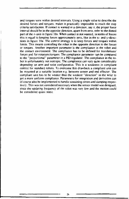
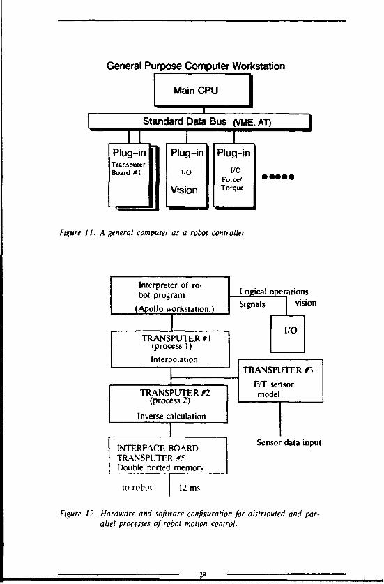
The proposed solution is to use a general (computer) workstation and expandthe hardware with a Transputer based plug in board to handle heavy controlsystems calculations, see figure 11. The Transputer board is then interfacedto the servo control equipment, in this case the servos in the ABB S3 controlsystem. This is possible thanks to special designed software from ABB thatallows access to the S3 data bus via a double ported memory. The hardwareis partly bought (Transputer board) and partly self wired (Transputer basedmemory interface) [Bergqvist, 19911.
A first version of the controller consists of an Apollo computer workstation.a Transputer equipped plug in board, a Transputer and double ported memory7
as interface to the servo computer of the ABB S3 controller, see figure 12 .The main computer (Apollo) is where the actual robot programs are executed.
27
General Purpose Computer Workstation
Main CPU
Standard Data Bus (VME, AT)
Plug-inTransputerBoard #1
|
Plug-in
I/O
Vision
1Plug-in
I/OForce/Torque
Figure II. A general computer as a robot controller
Interpreter of ro-bot program
(Apollo workstation.)
TRANSPUTER #1(process 1)Interpolation
TRANSPUTER #2(process 2)
Inverse calculation
INTERFACE BOARDTRANSPUTER #5Double ported memory
to robot 12 ms
Logical operationsvisionSignals
I/O
TRANSPUTER #3
F/T sensormodel
Sensor data input
Figure 12. Hardware and software configuration for distributed and par-allel processes of robot motion control.

This is on the standard program execution level for the workstation, why eg.a robot simulation system could be switched between simulation and controlof the real robot. Different levels of programming interfaces can be implem-ented to meet the requirements of various categories of programmers. All robotspecific commands are implemented as a set of modules which c.c linked tothe robot application program or the execution environment (if the programis interpreted at a higher level). The robot specific software is either executedon the main processor or on the external Transputers. This is transparent fromthe users point of view.
7.2 Transputer architecture
The robot command "move_robot" is executed on the Transputer no 1. wherethe interpolation takes place. In the first version, the interpolation is of lineartype [Herbertsson. 1990]. The call is parametric with parameters specifyingstart position (the current one is default), end position and end effector veloc-ity. The path is interpolated into incremental movements of 12 ms each, seefigure 13. Other interpolation routines are of course also possible. The interpo-
end position
stan position
Figure 13 Linear interpolated point to point control. Intermediate posi-tions reached every 12 milliseconds.
lated intermediate positions are pipelined to Transputer no 2, where the inversekinematic calculations are performed. The calculation method is an analyticsolution to the ABB IRB 2000 inverse kinematics, which results in joint anglesfor all six joints. The joint angles are pipelined to Transputer no 5, which isthe interface to the servo loop of the S3 controller. Each jont angle is heretransformed to resolver increments on respective motor shaft and deliveredto the servo controller. At this point the standard S3 servo takes care of thecontrol of each motor to achieve the desired positions.
Most of the robot specific tasks can be performed across the interface on trans-puter no 5. The double ported memory is divided into segments with a widevariety of purposes, sec figure 14.

Rel addr
$0$36$66$96$C4$14ASlCfl$24A$34E$38CS3BC$40C
step_bufflag_buffposreg_rspareIO_buffrobt_dataS3_dataparm_buffzero_pmIO_eventtext_buff
not
54 bytes48 bytes48 bytes46 bytes134 bytes128 bytes128 bytes260 bytes62 bytes48 bytes80 bytes
used
Use
Pos ref order dataServo lag dataCurrent pos.
Digital and analog inp.General dataGeneral dataParameter block data
Event def. digital inTextstring to display
Source
HostIRBIRB
IRBHostIRBIRB/Host
HostIRB
Figure 14. Memory layout of the dual ported memory. (Lindholm, 1990]
The result of this connection will be the possibility to supply the robot servoloop with new joint (motor increment) values every 12 ms, allowing oolicitsensor feedback as indicated in figure 12. The limitation to 12 ms updatingcycle time is on the ABB S3 side of system. The Transputer-Apollo based con-troller has an estimated cycle time of less than 1 ms. The controller can beapplied to any robot structure and brand by modifying the inverse kinematicsand the motor interface (in this case it is a servo control interface).
30

8. Compensating gravity forcesForce/torque sensors for industrial robots can be used in many tasks. The taskscan be divided into two major categories: contact and non contact operations.Contact based operations, also called compliant motion, uses the contact forcesto follow or search for surfaces, the other case concerns non contact whichcan be interesting when supervising gripper operations [Wennström, 1988].In the non contact case the sensed feature is the mass of the gripped object.The mass gives an idea of wether an object is gripped, it is the correct object,detect dropping etc.
8.1 End effector mass and orientation
Both categories of tasks can be affected by the mass of the end effector. Themost common way to eliminate the end effector mass is to use the reset biasfunction that is usually available on modern force/torque sensors. When thebias is reset, all the current forces are set to zero. After reset bias, only follow-ing changes in force/torques are detected, allowing relevant control be per-formed. For a task that doesn't require any rotations or at least no rotationsperpendicular to the gravitation vector, no further actions than the reset biasneed to be taken. The problem of gravity forces for changing end effector orien-tations is illustrated in figure 15. To handle this situation, the detected forces
F/T sensor
mG SP.TCP
SP.TCP
Figure 15. Varying gravity forces (mG) caused by different orientations.
have to be adjusted for the gravity forces of the end effector. If the end effectormass is considerable and the task requires a limited number of orientations,then the bias can be reset each time a new orientation is needed. The majordrawback is the time loss for each reset since the robot has to be at rest forsome time (in the magnitude of a second) to eliminate vibrations. Force/torque
31
controlled operations that include continuous orientation changes are only pos-sible within small ranges of angle without any compensation for gravity forces.The range depends on the end effector mass and its distribution as well asthe contact forces desired for the actual control operation. With continuouscompensation for end effector mass, force/torque control is independent oforientation changes.
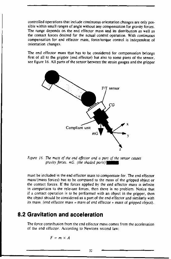
The end effector mass that has to be considered for compensation belongsfirst of all to the gripper (end effector) but also to some parts of the sensor,see figure 16. All parts of the sensor between the strain gauges and the gripper
F/T sensor
Compliant unitmG
Figure 16. The mass of the end effector and a part of the sensor causesgravity forces. mG. (the shaded parts) M É M
must be included in the end effector mass to compensate for. The end effectormass/(mass forces) has to be compared to the mass of the gripped object orthe contact forces. If the forces applied by the end effector mass is infinitein comparison to the relevant forces, then there is no problem. Notice thatif a contact operation is to be performed with an object in the gripper, thenthe object should be considered as a part of the end effector and similarly withits mass, (end effector mass = mass of end effector + mass of gripped object).
8.2 Gravitation and acceleration
The force contribution from the end effector mass comes from the accelerationof the end effector. According to Newtons second law:
F = m xA
32
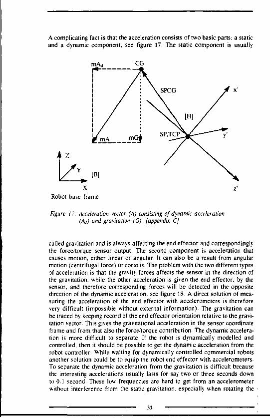
A complicating fact is that the acceleration consists of two basic parts: a staticand a dynamic component, see figure 17. The static component is usually
[B]
Robot base frame
Figure 17. Acceleration vector (A) consisting of dynamic acceleration(Ad) and gravitation (G). [appendix CJ
called gravitation and is always affecting the end effector and correspondinglythe force/torque sensor output. The second component is acceleration thatcauses motion, either linear or angular. It can also be a result from angularmotion (centrifugal force) or coriolis. The problem with the two different typesof acceleration is that the gravity forces affects the sensor in the direction ofthe gravitation, while the other acceleration is given the end effector, by thesensor, and therefore corresponding forces will be detected in the oppositedirection of the dynamic acceleration, see figure 18. A direct solution of mea-suring the acceleration of the end effector with accelerometers is thereforevery difficult (impossible without external information). The gravitation canbe traced by keeping record of the end effector orientation relative to the gravi-tation vector. This gives the gravitational acceleration in the sensor coordinateframe and from that also the force/torque contribution. The dynamic accelera-tion is more difficult to separate. If the robot is dynamically modelled andcontrolled, then it should be possible to get the dynamic acceleration from therobot controller. While waiting for dynamically controlled commercial robotsanother solution could be to equip the robot end effector with accelerometers.To separate the dynamic acceleration from the gravitation is difficult becausethe interesting accelerations usually lasts for say two or three seconds downto 0.1 second. These low frequencies are hard to get from an accelerometerwithout interference from the static gravitation, especially when rotating the
33

mGi
Figure 18. Newtons law of action and reaction. Fe in the direction ofthe end effector acceleration , Fs is the reaction force actingin the opposite direction on the sensor. The gravity force ofthe end effector (mG) and the reaction force (FGs) detectedby the sensor are equal in direction and magnitude.
end effector. A conclusion is that it is very complicated to perform dynamiccompensation in todays robots. The reasons are the complexity of the calcula-tions and the difficulties to acquire valid acceleration data for the end effector.The fact that a lot of operations can be helped by just compensating for thegravitation, the major effort is put on that.
8.3 Three different complexity levels
Because of the two different natures of the end effector acceleration, threelevels of compensation are developed.
* STATIC COMPENSATION
* SEMI DYNAMIC COMPENSATION
* DYNAMIC COMPENSATION
The gravity can be considered to be static as long as the robot installation issituated on the surface of the earth (at least fix relative to the field of gravity).The lowest level of complexity is the STATIC COMPENSATION which onlyadjusts sensor data for the gravity, refer to the mG-component in figure 17.
For a more accurate compensation, accelerations applied to the end effectorshould be considered. The compensation for dynamic accelerations can be di-vided into two complexity levels: complete dynamics and linear acceleration.Analyzing robot motion shows that movements to a high extent are linear, whycompensation for linear accelerations is motivated. This is called SEMJ DY-NAMIC COMPENSATION and includes gravity compensation (STATIC COM-PENSATION). Linear accelerations can be treated in similarity with gravity.
34

As for gravity, the only mass properties needed are the end effector mass andcenter of gravity [appendix C]. All calculations for gravity can be applied tolinear acceleration with only slight modification.
Level three is called DYNAMIC COMPENSATION. It includes level one anda complete compensation for all dynamical effects caused by robot motion.The end effector model must include all inertial parameters, like mass, centerof gravity, moments of inertia and products of inertia to facilitate dynamicadjustments of sensor data. The level of complexity for level three is consider-ably higher both for calculations and for acquiring acceleration data. Levelthree is not mathematically modelled in the paper [appendix C], just discussed.
35

9. Practical testsFor practical use of the sensor model, a software program was developed,called APPLICATIONS. The purpose of the program is to support a frameworkof necessary communication, initializations, robot and sensor specific func-tions.see figure 19. In this framework, robot applications can be implemented
Sensor modelparameters
APPLICATIONSMENU
InsertFollowTrack -e
Robot positions
Robot
comm.
1arap
1rscomm
Figure 19. Structure of the sensor model application program-
as subroutines called from a general application menu. For the purpose offorce/torque control, the sensor model control algorithm can be called withapplication specific parameters that are stored in a parameter file. Intermediate!•'. bot positions can also be called from a file and commanded to the robotduring the application program execution. Another program, called teach in,is used to teach robot positions and store into a position file as well as definingsensor model parameters for a specific application and store in a parameterfile for later use in the application program. These two programs have beenused to evaluate force/torque control and for different research related applica-tions.
9.1 Peg into hole insertion
The first test of the general task independent control algorithm was the wellinvestigated peg into hole insertion problem. It was natural because of the pre-
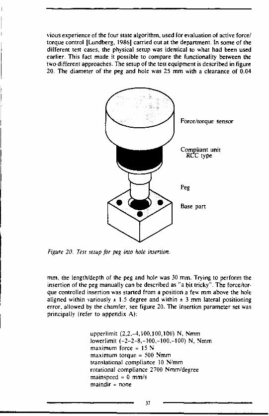
vious experience of the four state algorithm, used for evaluation of active force/torque control [Lundberg, 1986] carried out at the department. In some of thedifferent test cases, the physical setup was identical to what had been usedearlier. This fact made it possible to compare the functionality between thetwo different approaches. The setup of the test equipment is described in figure20. The diameter of the peg and hole was 25 mm with a clearance of 0.04
Force/torque sensor
Compliant unitRCC type
Peg
Base part
Figure 20. Test setup for peg into hole insertion.
mm, the length/depth of the peg and hole was 30 mm. Trying to perform theinsertion of the peg manually can be described as "a bit tricky". The force/tor-que controlled insertion was started from a position a few mm above the holealigned within variously ±1.5 degree and within ± 3 mm lateral positioningerror, allowed by the chamfer, see figure 20. The insertion parameter set wasprincipally (refer to appendix A):
upperlimit (2,2,-4,100,100,100) N, Nmmlowerlimit (-2-2-8,-100,-100,-100) N, Nmmmaximum force = 15 Nmaximum torque = 500 Nmmtranslational compliance 10 N/mmrotational compliance 2700 Nmm/degreemainspeed = 0 mm/smaindir = none
37
but the values were sometimes slightly changed for comparative reasons. Thebasic result was that the insertion could be performed with one control strategyas well as the four state algorithm used earlier. The stopping criteria was thatall forces should be within their respective limits which usually occurred whenthe peg reached the bottom of the hole. Hitting outside the chamfer could alsolead to termination of the insertion as the forces achieved their intervals. Thiscould also happen with the four state algorithm. The solution to the stoppingproblem was to add other criteria's, such as: travelled distance, elapsed timeand external signal. This was implemented in version two. The insertion speedwas in relation to applied forces (parameters to the control law), larger forces= increased speed.
9.2 Mass compensation
The test of the mass compensation algorithm consisted of several stocasticorientations of a 1.7 kg end effector moving without contact. The mass compen-sation task is to adjust sensor data for all forces and torques resulting fromend effector mass. Without environmental contact, the output should be zeroin all directions independent of orientation. To find the mass properties of theend effector, a series of orientations were carried out, detecting forces andtorques. The relations between forces, torques and orientations allowed massand center of gravity to be calculated for the end effector. Using these cali-brated data resulted in accurate adjustments. The errors from the compensa-tion algorithm was approximately ± 2 percent of the end effector mass, in thiscase in the range of ± 0.4 N and ± 25 Nmm (the sensor accuracy is within± 0.1N and ± 30 Nmm). Compared to contact forces in magnitude of 5 -15N for this end effector, the calculation errors are negligible.
9.3 Following a template
The use of templates is very common in industry. They are used to supporta variety of tasks, like cutting, carving, grinding, gluing etc. These are oftenmanual tasks that could be done with a robot. The robot program can be madewith a graphical offline programming system, but the robot path might notbe correct due to inaccuracies in the robot structure, payload etc. A nice wayto retrieve an accurate path in the actual robot coordinates would be to usea force/torque sensor in the robot wrist and follow the desired path along atemplate or a model of the object. If the same robot is used both for program-ming and execution, the path will be calibrated immediately if the payloadand TCP (Tool Center Point) are equal. The idea was initialized by Saab air-craft division in Linköping, and an aircraft template was used in the experi-ment. In order to maintain the sensor x-direction in the tangent to the templateedge, a special sensing device was designed, refer to figure 21. The sensingpoint and TCP was located in the central tip to which all forces and positionswere related, refer to figure 21. The front tip was merely used to maintainthe orientation along the template path. The principal parameter settings were:Keep contact with the underlying metal sheet and the template edge by issuing
38

Figure 21. A special designed tool for template following. Two sensingtips in contact with the surfaces causes forces and torques tomaintain the position and direction along the template.
forces in the negative z-direction and negative y-direction. The front tip canbe kept in contact with the template by maintaining a minor torque aroundthe negative z-axis. Note that the torque must be small in relation to the forcein the negative y-direction not to loose contact of the central tip. The fronttip can not apply force in the z-direction. The tangential motion can be definedindependent of tangential forces, or be defined by the specification of a forcein the negative x-direction that never occurs during the travel. The result isa constant tangential motion, only slightly affected by the friction forces. Thetest equipment was the usual ABB IRB1000, the Barry Wright force/torque sen-sor, an RCC compliant unit, special designed end effector and an aircraft wingpanel template. The correctness of the recorded path can be calculated to ±0.1mm in each direction, the calculation is based on measured forces and acompliance of 10 N/mm. The test was only 2.5 dimensional. The main problemto perform a full 3D path following is, besides the gravity forces (which canbe handled), the mechanical device to detect all direction forces and transferthem to the sensor. Some solutions are being evaluated, but all seem to suffersome drawback. With other kind of sensors it is probably possible, but goesbeyond the scope of this test.
9.4 Locating boiler connection holes
In a pre study to a EUREKA cooperation project, the division of AssemblyTechnology investigated the possibility to use force/torque sensors to locateholes. The partiripants in the pre study were Austria Email Austria, Österrei-chisches Forschungszentrum Austria, Esab AB Sweden and LiTH Sweden. Thetask of the robot cell was to assemble boiler connections to a number of holesin boilers of different sizes. The boiler could rotate in a horizontal fixture,

why all assembly could be done from above. Two robots should cooperate,one welding robot and one assembly robot which first located the hole in ques-tion. The rough hole positions were either known in advance or estimated byvision. The assembly robot with the force/torque sensor should give an accurateposition of the hole. The resulting position could then be used for assemblyand welding. In the force/torque experiment, a simple conic tool was used,see figure 22. The search process started from a position 5 to 10 mm above
Force/torque sensor
Compliant unit
Telescopic mounting
Conic tool
Connection hole
Figure 22. Test setup for the locating of boiler connections holes with aconic tool.
the hole until a reliable contact force from the edge of the hole was established.The actual hole position could be calculated from the remaining forces andthe compliance in the end effector together with the position retrieved by therobot. The search process took approximately 5 to 7 seconds until a resultingposition was calculated. The accuracy was within ± 0.1 mm in the "horizontaldirections", and within ± 0.2 mm for a vertical direction. The accuracy wasestablished by moving the hole with an x- y- table and performing severaltests in each position.
The tests presented here are among several other tests a way to evaluate thesensor model concept and the gravity compensation. The tests have been im-plemented in a software package, developed to serve as a test platform. Thetest software interface is just a simple hierarchical menu based program, withenvironment for defining and testing sensor model parameters. The definition
40

phase is usually an iterative trial and refining procedure. The sensor modelevaluation has proved that it is easy to specify parameters to achieve the de-sired behavior. An experienced user can achieve a good behavior in the very-first trial, but a few iterations are common. A good example is the locationof boiler connection holes, where the complete task was specified and testedin one hour. The gravity compensation allows reorientations during force/tor-que controlled operations. It is thereby a good contribution to the flexibilityof such operations. The mentioned tests have not been executed on the newopen controller concept, which is still under implementation.
41

10. Results and conclusionsThe presented work has resulted in three internationally published papers witha common interest in improving robotic contact operations. The basic problemin automatic assembly is the position and orientation inaccuracy. All modifica-tions to a system might cause inaccurate positions- This problem is especiallyprominent in flexible assembly systems where exchanges of assembly setupsare frequent. By tests, see e.g. chapter 9.1, and in literature e.g. [Van Brussel,1978], [Johansson. 1981] it has been proved that active and/or passive com-pliance can be a solution to the inaccuracy problem. A remark to active com-pliance is that it is too slow to be used in real applications. The proposed solu-tion is to use active sensor support for adaptations of bad positions in theadjustment period of a new installation and just supervision and error correc-tion in the daily work. Supervision takes no additional time, why the time re-quirements are fulfilled.
In order to improve the user friendliness of advanced sensors for robotcontrol.a sensor model concept was developed, chapter 6. [appendix A]. The conceptis based on a task independent control algorithm. The behavior of the robotis specified by a set of parameters instead of designing a new algorithm foreach task. Important parameters are: desired forces and torques, complianceand stopping criteria. The stopping criteria is a logical combination of stoppingrequirements. The stopping criteria has been difficult to implement in Pascal,but easy in the interpreting AML'2 language.
Practical tests have proved that new tasks can be specified with minor effortusing the defined parameters. A good example is the location of boiler connec-tion holes in chapter 9.4. However, good knowledge about the parameters aswell as the sensor and coordinate frames is required. To meet the need forsimple programming with sensor support, high level sensor functions shouldbe introduced. Sample high level functions are: insert, track, search, followetc [Johansson. 1992].
A drawback is that the sensor model becomes slower in complex situations,than a special designed algorithm. This is because the sensor model has tobe stopped and reconfigured for each sub task. So far, the implemented controlalgorithm has unfortunately slow access to the manipulator controller, whichreduces execution speed. This problem will be solved (the control will be closerto real time) in the new controller concept in chapter 7 and [appendix B].
The end effector mass is a limitation of the spatial working area for force/tor-que controlled robots. The orientation must be locked to avoid variations inthe gravity forces. To overcome this limitation and error source, a method forgravity compensation is developed [appendix C|. An automatic calibration pro-cedure gives an assurance of accurate mass properties of the end effector. Thedeviation from the theoretical output is small. A typical value of the errorscaused by inaccurate mass properties, orientation data and the computations.is less than ± 2rr of the end effector gravity force. Eliminating gravity forces

gives greater freedom to apply force/torque sensors in a broad spectrum oftasks and reduces error sources.
The problems experienced from the incorporation of external sensors into com-mercial robot controllers emerged into a concept for an open controller archi-tecture [appendix B] The hardware is based on a general computer worksta-tion equipped with Transputers in pipeline for interpolation, inverse kinematicsand servo control. The architecture is open for modifications and expansionsboth in hardware and software, which simplifies the incorporation of sensors.The computer workstation concept has a good potential for the integration ofmachines and office in the factory, due to mature network facilities.
The addressed problem with inaccurate positions in the assembly process hasbeen solved using a task independent control algorithm for a force/torque sen-sor. The first statement in the thesis (chapter 3) is verified by the implementa-tion of the sensor model (chapter 6) [appendix A), and the fact that practicaltests have been successful (chapter 9).
The intention with the sensor model was to simplify the use of force/torquesensor support in robotic applications. The second statement in the thesis isverified by practical tests (chapter 9) and by a comparison of the amount ofwork and knowledge required for specifying a task with parameters to the sen-sor model (chapter 6) [appendix A| and designing a new task specific algo-rithm. Combining the sensor model with a method for compensation of endeffector gravity forces (chapter 8) [appendix C] simplifies the use of force/tor-que sensor support even more. The sensor model is aiso a good platform forthe implementation of high level generic sensor functions [Johansson. 1992].
The value of the proposed controller architecture (chapter 7) [appendix B] canso far not be verified in amount cf time and money according to the thesis.However, it is reasonable to assume that the flexible software and hardwarearchitecture will make sensor integration easier and thereby less expensive.It is also possible to interact with the "real time" loop of the controller, whytouch time requirement? can be met.

References
[ABB. 1986] New Software Functions in Stage 4, IRB90M and IRB1000,ABB information report, CK 09-1405E, chapter 6.5,September 1986,
[An, 1^85] An C.H., Atkeson C.H., Hollerbach J.M., Estimation ofinertial parameters of Rigid Body Loads for Manipulators,proceedings of 24th IEEE Conference on Decision andControl, Fort Lauderdale, December 1985.
[Asada, 1985J Asada H., SlotineJ-J., Robotic Analysis and Control, NewYork, NY Wiley, 1985.
[Baucent, 1989] Baucent R., et Al, Identification of Dynamical Parametersof Robot Manipulators from external measurements, Euro-pean Journal of Mech. Eng, Vol 34, no 1, June 1989, pp21-26
[Bergqvist, 1991] Bergqvist Charlotta, An Interface Between a Transputer-Equipped Workstation and an ABB Robot Controller,Linköping University LJTH-IKP-EX-955, 1991.
[Van Brussel, 1978] van Brussel H., Simmons J., Automatic Assembly by ActiveForce Feedback Accomodation, 8th International Symposi-um on Industrial Robots, pp 181-193, 1978.
[Van Brussel, 1981] Van Brussel H., et al: Further Developments of the ActiveAdaptive Compliant Wrist (AACW) for Robot Assembly, Pro-ceedings of the Eleventh International Symposium on In-dustrial Robots, pp 377-384, 1981.
[Corbin. 1989] Corbin J., Silveri C , Open Network Programming, UNIXWorld, pp 115 Dec 1989.
[Drake, 1977] Drake S.H., Watson P.C., Simunovic S.N., High SpeedRobot Assembly of Precision Parts Using Compliance Insteadof Sensory Feedback, Seventh International Symposiumon Industrial Robots, pp 87-98, Tokyo Japan, 1977
[Duelen, 1991] Duelen G., Miinch H., Surdilovic D., Advanced RobotControl System for Manufacturing Processes, Annals of theORP, vol 40/1, 1991.
[Durrant-Whyte, 1987] Durrant-Whyte H.F., Consistent Integration andPropagation of Disparate sensor Observations, The Interna-
44

tional Journal pf Robotics Research, vol 6, no 3, Fall1987.
[Durrant whyte, 1988] Durrant-Whyte H.F., Sensor Models and Multisen-sor Integration, The International Journal pf Robotics Re-search, vol 7, no 6
[Elbestrawi, 1991]
[Ericsson, 1979]
[Fullmer, 1987]
[Fässler, 1990a]
[Fässler, 1990b]
Elbestrawi M.A., Yuen K.M., Srivastava A.K., Dai H.,Adaptive Force Control far Robotic Disk Grinding, Annalsof the CIRP, vol 40/1, 1991.
Ericsson CM., Johansson C , Anpassningsenhet för elimi-nering av centreringsfel och byrålådseffekt, Linköping Uni-versity, LTTH-IKP-R-147, 1979.
Fullmer D.M., Signature Analysis of Robotic Assembly For-ces-A Flexible Sensor System, 17th International Symposi-um on Industrial Robots, volume 2, pp 39 - 65, 1987
Fässler H., Concurrent Motion and Force Control for Mani-pulators Constrained by Stiff Contact, IEEE InternationalWorkshop on Intelligent Motion Control, Istanbul, Aug1990.
Fässler H., Manipulators Constrained by Stiff Contact: Dy-namics, Control, and Experiments, The International Jour-nal of Robotics Research, vol 9, no 4, Aug 1990.
[Goldenberg, 1987] Goldenberg A. A., Force and Impedance Contol of RobotManipulators, ASME proceedings, Winter Annual Mee-ting, 1987.
[Hayward, 1986] Hayward V., Paul R.P., Robot Manipulator Control underUnix RCCL: A Robot Control "C" Library, The Internatio-nal Journal of Robotics Research, vol 5, no 4, Winter1986.
[Herbertsson, 1990] Herbertsson, J., Robot Control Using a Transputer Equip-ped Workstation, Master Thesis: LiTH-KP-Ex-850, Uni-versity of Linköping, Linköping, Sweden, Oct. 1990
[Hirzinger, 1983]
[Hirzinger, 1983]
Hirzinger G., Brunet U., Fast and Self-Improving Comp-liance Using Digital Force-Torque-control, 4th Internatio-nal Conference on Assembly Automation, pp 268-281,1983.
Hirzinger G., Heindl J., Sensor programming - a new wayfor teaching a robot paths and forces/torques simultaneously,pp 549-558, 1983.
45

[Hollerbach, 1980]
[Huang, 1987]
[Johansson, 1981]
[Johansson, 1988]
[Johansson, 1989]
[Johansson, 1992]
[Kane, 1983]
[Kane, 1985]
[Kazeroni, 1986]
[Knight, 1987]
[Lee. 1987]
[Lindholm, 1990]
Hollerbach J.M., A Recursive Lagrangian Formulation ofManipulator Dynamics and a Comparative Study of Dyna-mical Formulation Complexity, IEEE Transactions on Sys-tems Man and Cybernetics, vol SMC-11, no 11, pp730-736, Nov 1980.
Huang H.P., Mc Clamrock N.H., Time Optimal Controlfor Robotic Contour Following Problem, in Proceedings IE-EE Conference on Robotics and Automation, pp.1140-1145, 1987.
Johansson C , Flexibel automatisk montering en systemana-lys, (in Swedish) Phd thesis: no 67, Linköping University,1981.
Johansson G., Demonstration av robotmontering med ut-nyttjande av datorsyn och kraftImoment-avkänning, (inSwedish) Linköping University, LJTH-IKP-R-511,1988.
Johansson G., A Software Package for Superior Control ofABB Robots, (in Swedish) Linköping University, LJTH-KP-R-588, 1990.
Johansson G.,Implementing the Force/Torque SensorModel Concept in AML/2, Linköping University, LJTH-KP-R-672, 1992.
Kane T.R., Levinson D.A., The Use of Kane's DynamicalEquations in Robotics, Int Journal of Robotics Research,Vol 2, no 3, pp 3-21, fall 1983.
Kane T.R., Levinson D.A., Dynamics: Theory and Applica-tion, Me Graw Hill, 1985, ISBN 0-07-37846-0
Kazeroni H.,,Houpt P.K., Sheridan T.B., Robust Comp-liant Motion for Manipulators part I and part II, IEEE Jour-nal of Robotics and Automation, vol RA-2, no 2, pp83-92, 93-105, 1986.
Knight J., Pomeroy S., Dixon H., Wybrow M., UltrasonicDistance Measuring and Imaging Systems for Industrial Ro-bots, Robotics, vol 3, no 2, pp 181-188, 1987.
Lee J., Apply Force/Torque Sensors to Robotic Applications,Robotics, vol 3, no 2, pp 189-194, 1987.
Lindholm J.. System Specification IRB2000-VME-hostCommunication, internal report: Labyrinten Data AB,1990.

[Lozano-Peréz, 1982] Lozano-Pérez Tomas, Robot Programming, A.I.Memo No. 698, Massachusetts Institute of Technology,December 1982.
[Luh, 1980]
[Lundberg, 1986]
[Marioli, 1988]
[Mason, 1981]
[Mills, 1989]
[Mukerjee, 1989]
[Nevins, 1973]
[Raibert, 1981]
[Roth, 1989]
Luh J.Y.S., et al, On-line Computational Scheme for Mec-hanical Manipulators, ASME Journal of Dynamic Sys-tems, Measurement, and Control, vol 1, pp 69-76, 1980
Lundberg I., Wennström L., Control of an Asea lrb 1000using a Force/Torque Sensor, LTTH-IKP-R-446, Linkö-ping 1986.
Marioli D., Sardini E., Taroni A., Ultrasonic DistanceMeasurement for Linear and Angular Position Control, IEEETransactions on Instrumentation and Measurement, vol37, no 4, Dec 1988.
Mason M.T., Compliance and Force Control for ComputerControlled Manipulators, IEEE Transactions on SystemsMan and Cybernetics, vol SMC-11, no 6, pp 418-432,1981.
Mills J.K., Goldenberg A.A., Force and Position Controlof Manipulators During Constrained Motion Tasks, IEEETransactions on Robotics and Control, vol 5, no 1, Feb1989
Mukerjee A., Joint Force Sensing for Unified Motor Lear-ning, Sensor Devices and Systems for Robotics, NATOASI series, Series F: Computer and systems Sciences,vol 52, pp 3-15, 1989.
Nevins J.L., Whitney D.E., The Force Vector AssemblerConcept, Proceedings: First CISM Symposium, Udine Ita-ly, 1973.
Raibert M.H., Craig, J.J., Hybrid Position/force Control ofManipulators, ASME Journal of Dynamic Systems, Mea-surement and Control, Vol. 103, No.l , June 1981
Roth N., Giinther K.G., RummelP., Beutel W., Model Ge-neration for Sensor-Guided Flexible Assembly Systems, An-nals of the CIRP, vol 38/1, 1989.
[De Shutter, 1988a] De Schutter J., Van Brussel H., Compliant Robot MotionI. A Formalism for Specifying Compliant Motion Tasks, TheInternationalJournal of Robotics Research, vol 7, no 4,Aug 1988.
47

[De Schutter 1988b] De Schutter J., Van Brussel H., Compliant Robot MotionII. A Control Approach Based on External Control Loops,The InternationalJoumal of Robotics Research, vol 7, no4, Aug 1988.
[De Schutter, 1988] De Schutter J., Simkens P., CAD-Based Verification andRefinement of High Level Compliant Motion Primitives, CADBased Programming for Sensory Robots, NATO ASI SeriesF: Computer and Systems Sciences, edited by BahramRavani, vol 50,, 1988
(Seliger, 1991]
(Silver, 1980]
[Simunovic. 1975]
[Söderqvist, 1989]
[Taylor, 1982]
Seliger G., Barbey J., Heinemeier H.-J., Feige M., TheFuture of Automation, Proceedings Robotikdagar Linkö-ping, May 30 - 31 1991.
Silver W.M., On the Equation of Lagrangian and NewtonEuler Dynamics for Manipulators, International Journal ofRobotics Research, vol 1, no 3, pp 60-70, 1980.
Simunovic S.N., Force information in Assembly Processes,Proceedings: 5th international Symposium on IndustrialRobots, pp 415-431, Sep 1975.
Söderqvist B. A.T., Wernersson Å., Monitoring Robotic As-sembly Using Accelerometers and Coherent Ultrasonic Sen-sors, S P E Intelligent Robots and Computer Vision VDJ.Systems and Applications, vol 1193, 1989.
Taylor R.H, Summers P.D., Meyer J.M., AML: A Manu-facturing Language, Robotics Research, No 1, 3 (Fall1982)
[Wennström. 1988] Wennström L., Krafi/moment-avkänning som medel vidflexibel automatisk montering, (in Swedish) Phd thesis: no182, Linköping university, 1988.
[Whitney, 1977] Whitney D.E., Force Feedback of Manipulator Fine Mo-tions, ASME Journal of Dynamic Systems, Measure-ment, and Control, vol 99, no 2, pp 91-97, 1977.
[Whitney, 1982] Whitney D.E., Quasi-Static Assembly of Compliantly Sup-ported Rigid Parts, Journal of Dynamic Systems, Measu-rement and Control, vol 104/65, Mar 1982.
[Whitney, 1987] Whitney D.E., Historical Perspective and State of the Artin Robot Force Control, The International Journal of Ro-botics Research, vol 6, no 1, pp 3-15, Spring 1987.
48

[Yang, 1986] Yang D.C.H. et al. Simplification and Linearization of Ma-nipulator dynamics by the Design of Inertia Distribution, In-ternational Journal of Robotics Research, vol 5, no 3,pp 120-128, 1986.
[Yao, 1989] Yao J., On Improving Robot Positioning Accuracy, Phd the-sis: Chalmers University of Technology, Gothenburg,ISBN 91-7032-434-4, May 1989.
[[Zhang, 1985] Zhang H., Paul R.P., Hybrid Control of Manipulators, Pro-ceedings: IEEE International Conference on Roboticsand Automation, pp 602-607, 1985
[Zebra] Zebra Robotics, Inc., The Zebra ZERO Technical Descrip-tion,

AppendixThis pan contains the three papers on which this thesis is based. The papershave been reformatted to be more readable and fit this size and style. Thecontent is however unchanged.
Appendix A:
General Parametric Sensor Model With External Communication Possibilities,Presented at the 2O:th ISIR in Tokyo.
Appendix B:
Towards Common Infrastructure for Advanced Manufacturing Control Sys-tems, Presented at the fifth ICAR in Pisa.
Appendix C:
An Efficient Mass Compensation Method for Force/Torque Control in Robot-ics, Presented at the Fourth World Conference on Robotics Research in Pitts-burg.
51