modern inswing door - marvin
TRANSCRIPT

2021-08-2119916241
Modern Inswing DoorSite Preparation Instructions
ABSTRACT: The Modern Inswing Door system requires proper site preparation to ensure optimal performance andoperation after installation. This instruction will provide the necessary information to properly prepare the wall open-ing for ease of installation and operational integrity.
Site preparation begins with preparing the opening for the specified sill system. The selected sill and substrate mustoffer the door system support, which spans the width and depth of the unit. The exterior of the sill must be completelysupported. Several sill options are available for consideration. Regardless of sill type, the foundation must supportthe sill height variance requirement of 1/16" (2) maximum across the entire sill length.
In conjunction with the sill, the framing of the rough opening must be installed plumb, square, and true within 3/16"(5).
I M P O R TA N TUnfactored superimposed load (Live, Wind, or Snow) deflection over the entire length of the unsupported span can-not be greater than 1/8" (3) after natural sag of the beam and permanent loads are in place.
NOTE: Numbers listed in parentheses () are metric equivalents in millimeters rounded to the nearest whole number.
I M P O R TA N TThe construction details shown within are not typical but are an example of various construction assemblies imple-menting the Modern Inswing Door and/or screen.
WARNING!Always practice safety! Wear the appropriate eye, ear, and hand protection, especially when working with powertools.
Table of ContentsWater Management System-Panning ......................... 2Sill Systems ................................................................ 3Construction Details.................................................... 8

2021-08-21 2 Modern Inswing Door19916241 Site Preparation Instructions
Water Management System-PanningWe require a sill pan for all Modern swinging doors in accordance with ASTM E2112. A sill pan is installed acrossthe bottom of the opening and integrated into the weather-resistive barrier (WRB). The illustrations below show thebasic requirements. Modification may be needed depending on your Rough Opening and alternative field prepara-tion. The table below is based on ASTM E2112.
Figure 1 Panning-varies based on multiple factors.
Types of Pan Flashing MaterialRigid Sheet 1 piece or multiple pieces Type IRigid Sheet Multiple pieces Type IIFlexible Membrane 1 Piece or multiple pieces Type IIICombination System Multiple pieces Type IVLiquid Membrane Continuous coating Type V
1 Sill interior dam must be at least 1/2" in height
2 Side end dams must be at least 6" in height
3 Seal any fastener holes through panning.

2021-08-21 3 Modern Inswing Door19916241 Site Preparation Instructions
Sill SystemsSill SupportThe performance and low profile sills implement a SillSupport system that is installed prior to the door frame.The location of the sill support varies depending on yourconstruction type.
Figure 2
Performance SillThis sill system requires a maximum of 1/16" (2) vari-ance in height across the entire length of the sill. A laserlevel may be helpful in preparing the opening. The Per-formance sill is designed to meet a minimum of DP40water testing but does NOT meet ADA height specifica-tions.
Figure 3 Performance sill
1 Frame exterior plane to sill support interior: 4 13/32" (112)
2 Nailing fin plane to sill support interior: 3 5/16" (84)
3 Panning
4 Sill Support

2021-08-21 4 Modern Inswing Door19916241 Site Preparation Instructions
Figure 4 Performance sill with screen
1 Interior sill height: 1 1/2" (38)
2 Exterior sill height: 2" (51)
3 Screen sill height with riser: 1 15/32" (37)
4 Screen depth: 2 7/8 (73)
5 Frame depth: 4 1/2" (114)
6 Frame depth with screen: 7 3/8" (187)

2021-08-21 5 Modern Inswing Door19916241 Site Preparation Instructions
Low Profile SillThis sill system requires a maximum of 1/16" (2) vari-ance in height across the entire length of the sill. A laserlevel may be helpful in preparing the opening. The lowprofile sill is designed to meet a minimum of DP25 watertesting and CAN meet ADA height specifications whenproperly installed.
Figure 5
Figure 6 Low profile sill without screen
Figure 7 Low profile sill with screen
1 Sill cover support
1 Sill height: 1 1/2" (38)
2 Sill depth: 4 1/2" (114)
1 Sill height: 1 1/2" (38)
2 Frame depth with screen: 7 3/8" (187)
3 Frame depth without screen: 4 15/32" (114)
4 Screen sill height with sill riser: 1 15/32" (37)
5 Screen depth: 2 7/8" (73)
6 Finished flooring (must be within 1/4" from top of sill for ADA)

2021-08-21 6 Modern Inswing Door19916241 Site Preparation Instructions
Weep Tube OptionsA weep tube adapter is available for the Performance and Low Profile sills. A minimum of 4" drop is required.Without the weep tube, the standard offering is a weep door.
Figure 8 Weep tube must terminate at least 4" below sill.
Figure 9 Weep tube terminating into drainage pipe
Figure 10 Weep door: do not block or seal to allow drainage.
1 4" (102)
2 Weep tube adapter
3 Weep door (fits on end of weep tube)
1 Weep door

2021-08-21 7 Modern Inswing Door19916241 Site Preparation Instructions
Saddle SillThis sill system requires a maximum of 1/16" (2) vari-ance in height across the entire length of the sill. A laserlevel may be helpful in preparing the opening. The sad-dle sill does meets ADA height specifications but is notrated.
Figure 11
Figure 12
1 Nailing fin plane to exterior edge of sill: 1 29/32" (48)
2 Frame exterior plane to exterior edge of sill: 13/16" (21)
3 Frame interior plane to interior edge of sill: 13/16"(21)
4 Sill height: 1/2" (13)
5 Sill depth: 6 1/8" (156)
6 Panning

2021-08-21 8 Modern Inswing Door19916241 Site Preparation Instructions
Construction DetailsFraming the opening at the header and side jambs for a Modern Inswing door will vary based on the type of sill usedand when a screen is used on the exterior. The examples shown below are not typical, and wall construction willvary. Use these details as a frame of reference only.
2x6 Framing
Figure 13 2x6 wood frame head jamb details
Figure 14 2x6 wood frame head jamb details with exterior screen
Figure 15 2x6 wood frame jamb details with OX RH configurationscreen
Figure 16 2x6 wood frame jamb details with X RH configurationscreen
1 1 7/16" (35)
2 3/4" (19)
1 1/2" (13)
2 2 3/32" (53)
3 2 7/8" (73)
1 1 15/16" (34)
2 7 3/8" (187)
3 2 7/8" (73)
4 2 3/4" (70)
5 Screen Inside Measurement
6 Screen Outside Measurement
1 1 15/16" (34)
2 7 3/8" (187)
3 2 7/8" (73)
4 2 3/4" (70)
5 Screen Inside Measurement
6 Screen Outside Measurement
2021-08-21 9 Modern Inswing Door19916241 Site Preparation Instructions
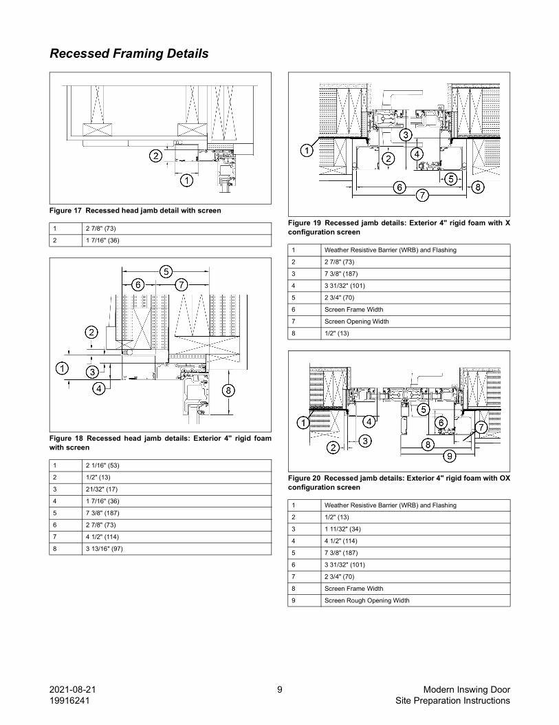
Recessed Framing Details
Figure 17 Recessed head jamb detail with screen
Figure 18 Recessed head jamb details: Exterior 4" rigid foamwith screen
Figure 19 Recessed jamb details: Exterior 4" rigid foam with Xconfiguration screen
Figure 20 Recessed jamb details: Exterior 4" rigid foam with OXconfiguration screen
1 2 7/8" (73)
2 1 7/16" (36)
1 2 1/16" (53)
2 1/2" (13)
3 21/32" (17)
4 1 7/16" (36)
5 7 3/8" (187)
6 2 7/8" (73)
7 4 1/2" (114)
8 3 13/16" (97)
1 Weather Resistive Barrier (WRB) and Flashing
2 2 7/8" (73)
3 7 3/8" (187)
4 3 31/32" (101)
5 2 3/4" (70)
6 Screen Frame Width
7 Screen Opening Width
8 1/2" (13)
1 Weather Resistive Barrier (WRB) and Flashing
2 1/2" (13)
3 1 11/32" (34)
4 4 1/2" (114)
5 7 3/8" (187)
6 3 31/32" (101)
7 2 3/4" (70)
8 Screen Frame Width
9 Screen Rough Opening Width