modularity is key when designing packet backbone networks for
TRANSCRIPT

BackgroundThe introduction of new access and coretechnologies as well as the convergence ofpacket- and circuit-switched traffic in mo-bile networks is a challenge for mobile op-erators, because they are responsible for net-work infrastructure and must deal with net-
work complexity, diverging requirementsand node limitations.
All too often, new nodes are introducedinto operator networks using ad hoc networkdesign with the aim of making the systemwork quickly. But the inevitable result ofimproper network design is an inflexibleand unscalable network that cannot copewell with even minor changes. To avoid acomplete redesign (which could jeopardizepast investments) after the network has beentaken into operation and the subscriber baseis growing, operators are often forced to ac-cept costly add-ons and workarounds.
Ericsson has collaborated with third-party networking vendors, such as JuniperNetworks, Extreme Networks, NetScreenTechnologies (now part of Juniper Net-works), and F5 Networks, to tackle these is-sues and provide a strong solution—the Mobile-PBN reference design.
Operator benefitsThe Mobile-PBN solution has been opti-mized and verified to work for networks ofany size, including multi-site networks. Of-
20 Ericsson Review No. 1, 2004
Modularity is key when designing packet backbonenetworks for mobile services Araceli Calle, Alberto Fernandez Bravo, Mounir Merhi, Jens Poscher and Helena Stjerna
Ericsson has developed a verified reference network design that optimallyintegrates general packet radio service (GPRS) and wideband code-division multiple access (WCDMA) technology with site and backbone IPinfrastructure. The solution, called Mobile Packet Backbone Network, orMobile-PBN, unites Ericsson’s core network products, and includes,among other things, optimum designs for the service network, the net-work management center, and network synchronization. The solution isoffered as part of Ericsson’s network design services.
The authors introduce the modular Mobile-PBN concept and describesome of its key modules—the multiservice backbone, circuit-switchedlayered architecture, and service network. They also describe the chal-lenges associated with verifying the Mobile-PBN and how these havebeen solved in the context of an end-to-end network. The Mobile-PBNfrequency synchronization solution has been described in a separate article.1
3GPP Third-generation Partnership ProjectA2EA AAL2 service end-point addressAAL2 ATM adaptation layer-2AMR Adaptive multirateATM Asynchronous transfer modeBGP Border gateway protocolBICC Bearer-independent call controlCAMEL Customized applications for mobile
network-enhanced logicCAP CAMEL application partCAPEX Capital expenditureCoS Class of serviceDiffserv Differentiated servicesDNS Domain name serverDSCP Diffserv code pointFRR Fast rerouteFWLB Firewall load balancerGCP Gateway control protocolGGSN Gateway GSNGMSC Gateway MSCGPRS General packet radio systemGSM Global system for mobile communi-
cationGSN GPRS service nodeIGP Interior gateway protocoliLB Internal load balancerIMS IP multimedia subsystemIP Internet protocolISDN Integrated services digital networkISUP ISDN user partIT Information technologyL2/L3 Layer-2/layer-3
LSP Label-switched pathMAP Mobile application partMGW Media gatewayM-MGW Mobile MGwMP-BGP Multiprotocol BGPMPLS Multiprotocol label switchingMSC Mobile switching centerMTP3 Message transfer protocol 3NAT Network address translationNTP Network time protocolO&M Operation and maintenanceOPEX Operating expenditureOSPF Open shortest path firstPAT Port address translationPBN Packet backbone networkPCM Pulse-code modulationPDB Per-domain behaviorPDU Protocol data unitsPFE Packet-forwarding enginePHB Per-hop behaviorPLMN Public land mobile networkPoI Points of interconnectionPoP Point of presencePSTN Public switched telephone networkPVC Permanent virtual circuitQoS Quality of serviceRAN Radio access networkRANAP RAN application partRE Routing engineRED Random early discardRNC Radio network controllerRNS Radio network subsystem
RNSAP RNS application partRSVP Resource reservation protocolRSVP-TE RSVP with traffic engineering exten-
sionsSAPI Service access and protection infra-
structureSDH Synchronous digital hierarchySGSN Serving GSNSGW Signaling gatewaySIGTRAN Signaling transportSLB Server load balancerSNF Service network frameworkSN-IPI Service network IP infrastructureSONET Synchronous optical networkSPF Shortest path firstSS7 Signaling system no. 7STM-1 Synchronous transfer mode data
rate 1 (155.52 Mbps)STP Signal transfer pointTCP Transmission control protocolTDM Time-division multiplexingTrFO Transcoder-free operationTSC Transit switching centerUMTS Universal mobile telecommunica-
tions systemUTRAN UMTS terrestrial radio access net-
workVPN Virtual private networkWCDMA Wideband code-division multiple
accessWRED Weighted REDWRR Weighted round-robin
BOX A, TERMS AND ABBREVIATIONS

Ericsson Review No. 1, 2004 21
fered as part of Ericsson’s professional net-work design services, the solution • reduces costs of network design, verifica-
tion and type acceptance, which translatesinto shorter time to revenue (Figure 2);
• reduces risks—it has been verified, is scal-able, and future-proof;
• relieves operators of the cumbersome taskof network design—they can rely onEricsson’s professional services staff toadapt the solution to existing networksand instead concentrate more fully on cru-cial revenue-generating end-user services;and
• reduces supplier relationships—Ericssonowns the overall solution and assumes re-sponsibility for designing, migrating andsupporting the entire network, and guar-antees integration into Ericsson core net-work and GPRS and WCDMA solutions.
In addition, operators receive a verified,highly flexible, and future-proof network
Mobile-PBN Customer-unique system integration
Annualized support costTesting costInstallation costDesign costVendor managementEquipment cost
Relative total cost expressed as % of equipment cost
Cost saving potential Calculations in one operator scenario showed cost savings of nearly 35%
Figure 2 Benefits of Mobile-PBN: reduced time and costs of system integration.
Primary site 1
Concentrator site
Primary site 2
Secondary site 2
Secondary site 1
IP core
IP backbone access
UTRAN and GSM/GPRS
access
UTRAN and GSM/GPRS
access
UTRAN and GSM/GPRS
access
UTRAN and GSM/GPRS
access
UTRAN and GSM/GPRS
access
GRX or roaming partners
GRX or roaming partners
GRX or roaming partners
Local and remote GSM and PSTN
Internet
Corporate access
Corporate access
Corporate access
Corporate access
Local and remote GSM and PSTN
Local GSM and PSTN
Figure 1The Mobile-PBN reference network.

design to which any number of modules canbe added—for example, corporate access,network management and data optimiza-tion.
Mobile-PBN, a totalnetwork solutionThe Mobile-PBN solution consists of net-work modules that combine to provide net-work functions built on backbone and siteinfrastructure. The modules contain func-tionality for GPRS and WCDMA, circuit-switched voice, packet-switched data (in-cluding inter-PLMN roaming and corporateaccess), service network IP infrastructure(including Internet access), charging, dataoptimization, network management andlawful interception.
The site infrastructure provides denseEthernet connectivity, switching function-ality, frequency synchronization, networktime protocol (NTP), and domain nameserver (DNS) services. The transport mod-ules use IP routers or asynchronous transfermode (ATM) switches to implement thecore, distribution and access layers neededfor inter-site connectivity.
Mobile-PBN reference designThe modular concept simplifies the defini-tion of different kinds of site. The Mobile-PBN uses these definitions to design and di-mension a detailed reference network for a“virtual operator” (Figure 3). The networkconsists of • two Primary sites—these include the ma-
jority of modules, in particular, the oper-ation and maintenance (O&M) module,which is needed for managing the com-plete network;
• two Secondary sites—these have fewermodules but maintain core network func-tionality; and
• a Concentrator site—this is mainly formobile access and corporate connectivity.
The reference network is dimensioned tosupport a very large number of GSM andWCDMA subscribers. Besides the large ref-erence design, the Mobile-PBN containstwo very cost-effective designs for small, single-site networks. The first is a purepacket-switched solution that makes use ofEricsson’s combined GPRS service node(CGSN); the second is a split serving GSNand gateway GSN (SGSN-GGSN) designwith added circuit-switched functionality.Each network includes advanced securityprotection using firewalls and can be migrated to the multi-site Mobile-PBN design.
The reference design meets operator re-quirements for availability, redundancy, security and scalability. Security considera-tions include a policy and multi-layered security architecture that defines logical security zones and areas of physical access.Traffic is not allowed to move from one zoneto another without fulfilling the conditionsof pre-configured firewall policies.
Multiservice IP backboneMost operator networks already have, or willinclude, geographically distributed sitesconnected by a transport infrastructure. Al-though a variety of switching equipmentcan be used to transport different services,
22 Ericsson Review No. 1, 2004
Primary 1 Primary 2
Concentrator Secondary 1 Secondary 2
PS-A
SI-A
SI-B
TR-A
TR-C
SI-B
TR-B
SI-B
TR-B
Mobile backbone inter-site links
Transport module
Site infrastructure module
Packet-switched module
Circuit-switched module
Mobile access module
O&M module
Charging module
Lawful intercept module
Service network terminal NAT module
Service network server farm module
A,B,C and 1, 2, 3 suffixes indicate different variants of the same module
SI-A
TR-A
PS-A PS-A
PS-B CS-B CS-COM-B OM-B
PS-A
MA-2 MA-3
MA-2 MA-3 MA-2 MA-3
MA-2 MA-3
LI OM-A OM-B T NAT
CH SN NAT
MA-2 MA-3
OM-B
SN SF
Figure 3 Mobile-PBN modules by site and function in a multi-site environment.

Ericsson Review No. 1, 2004 23
there is a more profitable approach, namelycommon transport. Simplifying the net-work in this manner reduces capital expen-diture (CAPEX) and eliminates the over-head of operating and maintaining multi-ple transport networks. It also significantlylowers operating expenditures (OPEX). TheEricsson Mobile-PBN facilitates conver-gence by providing backbone transportmodules built around best-in-class IProuters that can support the most stringentservices required by present-day and futureGPRS and WCDMA networks.
Challenges of designing apacket backbone network InterfacesThe first requirement put on a multiservicebackbone is that it must be able to replacelegacy network equipment. In this context,it is clear that the transport modules in thebackbone must provide the same kinds ofinterfaces as offered by existing networks(Figure 4). The site routers of the Mobile-PBN have been selected to offer a rich vari-ety of interfaces. They allow connections toATM and Frame Relay and are frequentlyused to connect core nodes and peering net-works. For Ethernet-based interfaces, thepreferred means of aggregation, and of op-timizing costs, is to use the Ethernet switch-es in the site infrastructure.
Traffic separation in VPNs
Unfortunately, multiservice backbone inte-gration is not as simple as “plugging” clientnodes into a new box. Different client net-works need distinct transport services inseparate network layers (Figure 5). For in-stance, in the Core Network 3.0 timeframe,Ericsson’s mobile media gateway (M-MGW) can deliver circuit-switchedtraffic in the form of IP packets (limitedavailability) or ATM adaptation layer-2(AAL2) ATM cells. The latter solution re-quires functionality not found in ordinaryIP backbones. The Mobile-PBN backboneprovides this functionality using virtual pri-vate networks (VPN) based on multiproto-col label switching (MPLS).
MPLS is a key technology enabler, whichin conjunction with other protocols, pro-vides a common framework that supportsKompella layer-2 and RFC 2547bis layer-3VPNs in an effective and scalable way.MPLS separates the control plane (which re-mains IP) from the forwarding plane, there-
SAPI T-NAT
MGW MSC
DNS
L2/L3 Eth
L2/L3 Eth
PS modules
Site infrastructure module
CS modulesService network module
Transport module
Mobile access modulesOperation and maintenance modules
RNC
Router
Corp router
Corp router
ISP router
Router
Leased line
Internet
BSC
Gp FW
GGSN
SGSN
O&M FW
O&M DNS O&M app O&M app
PCU
ATM
FE GEATM E1 (FR)
SDH, FE, GE, ....
NxDS0, E1 (PPP)
GE
FEGE
Backbone scope
NTP
Figure 4Mobile-PBN backbone interfaces in the Mobile-PBN.
Corp A
PS clients
Site router
L3 (IP) connectivity
L2 (ATM) connectivity
MPLS connectivity through traffic-engineered backbone
MP-BGP Protocol families exchanged
(IPv4, VPN-IPv4, 12VPN)
Site router
PS clients
CS clients CS clients
Corp A
Iu PSIutPS
Iu L2VPN Iu L2VPNMGW L2VPN
MPLSIPv4 PPP HDLC SDH
MPLSATM PPP HDLC SDH
MGW L2VPN
CN L3VPN CN L3vpn
Corp B
Corp B
Corp n
Figure 5 Traffic separation in the backbone.

by solving the problem of forwarding non-IP protocol data units (PDU). Switching inthe backbone is thus no longer dependenton looking up IP headers, because the for-warding of layer-2 and layer-3 (L2/L3)PDUs is based on MPLS labels, which areprepended to the PDUs when they enter thebackbone. The core of the aforementionedcontrol plane is based on the border gatewayprotocol (BGP) with multiprotocol exten-sions (MP-BGP) and traffic-engineering-enhanced link-state internal gateway proto-col (IGP)—for example, open shortest pathfirst (OSPF)—and finally, on the resourcereservation protocol (RSVP).
The flexibility of a large-scale protocollike MP-BGP makes it possible to exchangeVPN information (associated interfaces, en-capsulation, topology, and so on) on the dif-ferent VPN types. OSPF and RSVP-TE per-mit label-switched paths (LSP) to be imple-mented between network sites without theconstraints imposed by shortest path first(SPF) algorithms inherent in link-state pro-tocols. Thus, we see that transmission re-sources are used efficiently. Likewise, sys-tem availability is maintained because theSPF algorithms can quickly converge whenthe topology changes.
The ability to transport traffic on differ-ent layers is not the only benefit of VPNs.Addressing and numbering issues are alsogreatly simplified, because client networksperceive the backbone as if it were dedicat-ed—a benefit that eliminates complex co-ordination between the client networks.
Traffic differentiation The backbone is also greatly simplifiedthanks to a reduction in infrastructure andbecause traffic flows that were previouslycarried independently can now share net-work elements and transmission resources.If contention occurs, quality-of-service(QoS) mechanisms ensure that each type oftraffic is forwarded according to its require-ments.
The QoS solution for the backbone em-ploys differentiated services (Diffserv) overMPLS. From a design point of view, the fol-lowing points must be considered:• ability of the backbone to implement for-
warding treatments or per-hop behaviors(PHB) to which the traffic flows aremapped according to traffic class;
• ability of client nodes to communicate thecorrect QoS requirement; and
• mechanisms for dealing with local andbackbone-wide congestion.
Implementing PHBsThe success of this type of solution relies onthe selection of a scheduling algorithm thatserves the queues used to implement thePHBs at each site router (Figure 6). Therouters from Juniper Networks employ acombination of weighted round-robin(WRR) and priority disciplines, which de-fine two priority levels. The approach up-holds the strict delay and jitter requirementsassociated with voice traffic while giving fairtreatment to lower-priority traffic classes.
Each PHB definition must also be com-plemented with buffer sizes that are appro-priate for the delay or jitter characteristicsof the traffic class to be served. In addition,for each PHB, a percentage of the availablebandwidth must be allocated between eachpair of sites according to relative traffic vol-umes. The coherent application of PHBsthrough the backbone routers leads to per-domain behaviors (PDB), which is to saythat bearer services remain between re-quired levels, regardless of which path is fol-lowed through the backbone.
Communicating QoS needs
Diffserv code points (DSCP) are used to maptraffic flows to the appropriate PHBs. TheDSCPs are inserted by the client node or canbe allocated to the L2/L3 PDUs as they enterthe backbone. Diffserv-capable nodes, suchas GSNs, insert a DSCP that adequately re-flects the PDP context. The common pro-cedure, when the same organization ownsthe core and backbone networks, is to sup-
24 Ericsson Review No. 1, 2004
Q0
Interactive background
Conversational
Streaming
Network control
Buffer size
Priority
Low
High
Low
High
Physical output port
PIC
Scheduling discipline (WRR + priorities)
The time developed to service each queue is proportional to the bandwidth required in the interface
According to delay/jitter requirements
Q1
Q2
Q3
Figure 6 PHB implementation at site routers—queue, weight and priority configurations.
Ericsson Review No. 1, 2004 25
port this DSCP from an end-to-end per-spective. If the IP nodes cannot handle Diffserv (for example, P2.1 RNCs), then theingress site router inserts the DSCP basedon a multi-field discriminator filter config-ured in the site router interface that connectsto the client node.
Non-IP client nodes, such as media gate-ways that deliver AAL2 ATM cells, can usethe site router resources by mapping theconnecting interface (logical or physical) tothe proper forwarding class in the ingressrouter. This mapping is defined when theinterface is configured.
In every case, Diffserv treatment in theMPLS backbone network is encoded in theMPLS header using E-LSPs. This means thatthe applicable quality of service is derivedfrom the experimental bits in the MPLSheader (Figure 7).
Dealing with congestion
To work effectively, the QoS approach re-quires mechanisms for dealing with localand backbone-wide congestion. The mech-anism for managing local congestion, calledweighted random early discard (WRED),enables different drop profiles to be assignedto different kinds of traffic. A less aggres-sive random early discard (RED) drop pro-file is assigned to critical packets; a more ag-gressive profile is assigned to other packettypes.
With the exception of transmission con-trol protocol (TCP) traffic, this mechanismby itself is not sufficient to avoid long-termcongestion. A backbone-wide solutionwhich is based on traffic conditioning at theedges of the backbone and which is valid forall kinds of traffic must be employed to keeptraffic injected by different sources withinacceptable limits. Ericsson recommendsthat policers should be employed in the siterouter interfaces connected to client nodes.The policing mechanism in routers from Ju-niper Networks employs the token bucketalgorithm, which enforces a limit on aver-age bandwidth while allowing bursts of upto a specified maximum value.
Availability The infrastructure must also offer the samelevel of availability found in existing pub-lic telecommunications networks. The Mobile-PBN view is that reliable servicesare built on top of reliable networks, whichin turn, are based on reliable platforms.
The Mobile-PBN recommends the usageof IP routing devices with separate routing
and forwarding planes. This gives efficientdeployment of graceful restart implementa-tions of the protocols used in the controlplane. Separation guarantees the perfor-mance of the packet-forwarding engine(PFE) even with high levels of route insta-bility. Moreover, even extremely large vol-umes of traffic cannot limit the ability of therouting engine (RE) to maintain peer rela-tionships and calculate routing tables. Inshort, a clean separation of these two func-tions yields superior forwarding perfor-mance and a highly reliable system.
Equipping the routers with redundantrouting engines and packet-forwarding en-gines further increases availability. Therouting engines support hitless failover,which means that in the event of failure orplanned downtime (for software upgrades)the packet-forwarding engine can maintainforwarding while the redundant routing en-gine takes over (for a period of, say, 2-3 min-utes).
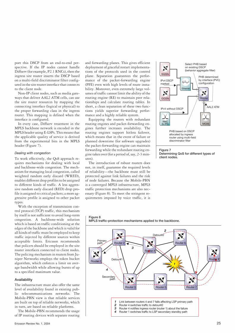
The introduction of robust routers doesnot, in itself, guarantee the required levelsof reliability—the backbone must still beprotected against link failures and the riskof node failures. Because the Mobile-PBNis a converged MPLS infrastructure, MPLStraffic protection mechanisms are also nec-essary (Figure 8). To meet the stringent re-quirements imposed by voice traffic, it is
IPv4 DSCP marked
IPv4 without DSCPAAL2 ATM
PHB determined by interface (PVC) configuration
Select PHB based on existing DSCP (behavior aggregate filter)
PHB based on DSCP allocated by ingress router using multi-field discriminator filter
Router
SGSN
RNC (Iu PS)
GGSN
Ethernet
MGW
Figure 7Determining QoS for different types ofclient nodes.
Router 1
Router 2
Router 4
Detour#1
4
1
2
3
1 2 3 4
Link between routers 4 and 7 falls affecting LSP primary path Router 4 switches traffic to detour#2 Router 4 notifies ingress router (router 1) about the failure Router 1 switches traffic to LSP secondary standby path
Detour#2
Primary path
Secondary path
Router 6
Router 3 Router 5 Router 7
Router 8
Figure 8 MPLS traffic-protection mechanisms applied to the backbone.

recommended that two levels of pre-computed label-switched paths be used. Atlocal levels, the fast reroute (FRR) mecha-nism is used. At backbone-wide levels, sec-ondary standby paths are recommended.
The fast reroute mechanism provides al-
ternative paths that the router upstream ofan outage can use to quickly reroute trafficaround a failed link or node. The same routernotifies the ingress router about the failure,causing it to switch traffic to the secondarypath. The use of pre-computed alternatepaths significantly reduces recovery times.Indeed, it puts them on a par withSDH/SONET protection mechanisms. Tobe effective, the secondary paths and otheralternative paths must not share fate withthe primary label-switched path.
In large networks, the combination ofthese two mechanisms (FFR and secondarystandby paths) provides optimum trafficprotection. In networks with simpler topol-ogy, such as the Mobile-PBN reference net-work, secondary standby paths suffice.
To obtain the best results when applyingthese mechanisms, Ericsson recommendscompliance, at physical and logical levels,with a set of connectivity guidelines for thebackbone and different client networks.
Circuit-switched layeredarchitecture The Third-generation Partnership Project(3GPP Release 4) has standardized the circuit-switched layered architecture in re-sponse to operator requirements • to cut costs in the transmission network;• to aggregate O&M-intensive nodes in
central sites; and • to spread the public switched telephone
network (PSTN) points of interconnec-tion (PoI) close to the destination, to ob-tain local switching.
Ericsson’s solution to the circuit-switchedlayered architecture, which is based on mo-bile switching center (MSC) servers and mo-bile MGWs, enables operators to introducethe new technology using ATM in the trans-port network (for the user-plane) and sig-naling system no. 7 (SS7) signaling. A step-by-step evolution simplifies migration ofthe core network to IP. The first step entailsthe introduction of SS7 over IP signalingtransport (SIGTRAN) for control signaling.Later, the user-plane in the core networkwill also be based on IP transport.
Core network architecture The control and connectivity layers in thecircuit-switched layered architecture arelogically separated. However, the servers(MSC, GMSC, TSC and SGW) retain thesignaling protocols used in the non-layeredarchitecture. Two additional protocols—
26 Ericsson Review No. 1, 2004
Site 1 Site 2
RNC
Iu
RANAP
GCP
GCP
N-ISUP
External networks (TDM)
Q.BICC
Q.AAL2
ATM switches
Mobile PBN
Connectivity layerSignalingUser plane
CIC
Network control layer
MGW
MSC server TSC server SGW
AMR coding 12 kbpsAAL2 switchTRA
Figure 9Schematic view of the layered architecture.
RNC
RNC
PSTN
M-MGW
WCDMA RAN Core network
RANAP
Q.2630
Q.2630
PCM
IuCPISUP
IuUP
IuUP (AMR)
IuUP (AMR)
Nb (PCM)
RNSAP
Nc
BICC
GCP
Mc Mc
External networks
MSC/TSC server
TSC
VLRG-MSC
SGWSTP
AAL2
M-MGW
MSC/TSC server
TSC
VLRG-MSC
SGWSTP
AAL2
Figure 10 Interfaces used in the layered architecture.

Ericsson Review No. 1, 2004 27
the bearer-independent call control (BICC)and gateway control protocol (GCP)—arealso implemented (Figure 9). BICC intro-duces control of ATM and IP bearers in theconnectivity layer. GCP enables the serversto control and manipulate the resources of amedia gateway. Legacy narrowband proto-cols might also need a signaling gateway(SGW) to convert signaling bearers.
Benefits The new architecture helps reduce the costsof operating the network. In traditional net-works, the MSC and transit switching cen-ter (TSC) nodes are not centralized. Conse-quently, daily maintenance and hardwareand software upgrades require O&M per-sonnel to work from several locations.
Leased lines in the TDM-based core net-work are dimensioned for 64 kbps voicechannels. Existing voice compression sys-tems are not end-to-end solutions. Howev-er, setting up a network in the layered ar-chitecture to place the voice transcoders atthe edge of the network permits true end-to-end transmission of coded voice to savebandwidth in the backbone. In addition,voice quality enhancements, such astranscoder-free operation (TrFO), whichwas standardized in 3GPP Release 4, willsoon become available.
Another benefit of the new architecture isthe decentralization of media gateways,which allows the opening of multiple PSTNpoints of interconnection and enables oper-ators to carry calls as far as possible in theirown networks.
Technology The initial solution for the layered core net-work is based on an ATM network withAAL2 switching. The functionality andbenefits of AAL2 switching with statisticalmultiplexing in the UMTS terrestrial radioaccess network (UTRAN) have been dis-cussed previously.2 Figure 10 shows all rel-evant payload and signaling interfaces.
The Ericsson mobile media gateway com-bines all transcoder, echo canceller, andmulti-part device functionality. A signalinggateway is added on top of the mobile mediagateway to convert the SS7 signaling bear-er from ATM to TDM and vice versa. TheM-MGW serves as a cross-connect for ATMpermanent virtual circuits (PVC) and as anAAL2 switch. AAL2 switch functionality isespecially important for the codec-at-the-edge feature, and for redundancy at higherlayers.
Thanks to AAL2 switching and dedicat-ed bearer control protocols (Q2630 orQ.AAL2) in the transport layer, the Iu in-terface can be extended through the core net-work domain to serve the nearest M-MGWof the region to which a call is to be deliv-ered. The radio network controller (RNC)sets up the AAL2 connection hop-by-hop tothe final M-MGW. It uses the AAL2 serviceend-point address (A2EA) to address thedestination node. Only one media gatewayis needed to transcode AMR-coded voiceover Iu from the RNC to pulse code modu-lated (PCM) voice. Operators thus savebandwidth in the backbone—PCM requiresthe equivalent of 84.8 kbps in bandwidth,whereas AMR-coded voice over Iu requiresonly 12.2 kbps end-to-end. The same AAL2network also facilitates Iur connections be-tween RNCs. The next step is to build a corenetwork that is as resilient and delivers thesame perceived quality of service as TDM-based networks.
Mobile-PBN circuit-switched design The Primary sites aggregate the MSC andTSC servers as control layer nodes. The MSCservers control the RNCs. For optimal callrouting, the MSC servers also control everyM-MGW in the network. The Secondarysites only contain M-MGWs. The MSC
AXI 520 AXI 520
AXI 520 AXI 520
Primary site
RNC
RNC
Iu lur
Iu lur
Local PSTN
Local PSTN
M-MGW
M-MGW
M-MGW
M-MGW M-MGW
M-MGW
M-MGW
MSC/TSC server
MSC/TSC server
Mobile PBN IP backbone
ATM transport using L2 VPN technology
AAL2 transit layer Iu, Iur, Nb
N x ATM/STM1 N x TDM/E1
Primary site
Figure 11 Mobile-PBN circuit-switched reference design.
servers in the Primary sites control theRNCs and MGWs in the Secondary sites viaGCP. The Concentrator sites solely containthe WCDMA access module.
The sites are interconnected by the multiservice backbone. The different sitestunnel ATM traffic through using layer-2VPNs. This modular approach enables Mobile-PBN networks to scale from one-site solutions to very large WCDMA net-works.
Connectivity Ericsson’s layered architecture solution callsfor static ATM PVCs between each node inthe AAL2 network. Each ATM PVC carriesone AAL2 path, which in turn, can carry 248AAL2 connections or calls (Figure 12).
Obviously, given the growing number ofM-MGWs, a full mesh of physical linkswould be uneconomical and difficult tomanage. An alternative approach is to con-nect the M-MGWs by means of cross-connected ATM PVCs, but this is also quitecomplex. Therefore, to achieve full connec-tivity of M-MGWs and the required redun-dancy on the AAL2 switching layer, Ericsson has introduced access layer andtransit layer hierarchy.
The concept is similar to legacy TDM orIP networks. Two M-MGWs at each site be-long to the AAL2 transit layer. Every AAL2transit M-MGW is fully meshed over the
backbone using label-switched paths.Therefore, should the AAL2 path or nodefail, the destination site can still be reached.The backbone is responsible for internalAAL2 path redundancy (Figure 8).
The remaining M-MGWs at the site con-nect on the AAL2 layer to the two transitM-MGWs. From the viewpoint of the AAL2layer, the RNC must adhere to this samestructure—that is, each RNC must connectto two different M-MGWs over redundantlinks. Thanks to this modular architecture,every AAL2-based interface (Nb, Iu, Iur) canuse this transport layer. If a link, board orthe next AAL2 switch fails, an alternateroute is always available.
This strictly hierarchical network also al-lows certain nodes to be grouped in A2EAaddressing—for example, the nodes at a site.This, in turn, makes it possible to use sin-gle routing entries for sites, because thetransit AAL2 switches must only analyze thelongest prefix in the address field. What ismore, the addition of nodes only requireschanges in a few routing tables.
To guarantee redundancy, the MSC andTSC servers must connect to two M-MGWs,which also serve as signal transfer points(STP). The internal STP functionality of theM-MGW forms the new broadband SS7 net-work. The broadband SS7 layer mirrors thehierarchical structure of the AAL2 layer.The transit M-MGWs, which make up the
28 Ericsson Review No. 1, 2004
STM-1 link
ATM PVC
AAL2 path248 AAL2 connections (calls)
Figure 12 AAL2 connections.
Mobile access to hosted service via SN-APNMobile access to hosted service via CSInter-server connectivity via SAPI
Operator server connectivity to Internet via server
Internet user accessto hosted service
Internet access via SN-APNInternet access via CSInternet access via internet APN
SN-APN
CS
IAS
SN-VPN
GGSN
Internet APN
Internet
SAPI
Internet fixed users and servers
Server
Server Enabler
Server
SN IPI
Server farm module
Terminal NAT module
TNAT
PAT High availability
Load balancing Security Port flexibility Routing Traffic separation DNS service Server NAT High availability Inter-server connectivity
Mobile access
Mobile-PBN backbone
Mobile-PBN backbone
Internet VPN
SiteR ISP
Figure 13 Role of SN-IP infrastructure in mobile net-works.

Ericsson Review No. 1, 2004 29
transit SS7 STP network, route all inter-sitesignaling (RANAP, RNSAP, GCP, MAP,CAP, BICC and ISUP) on the message trans-fer protocol 3 (MTP3) level.
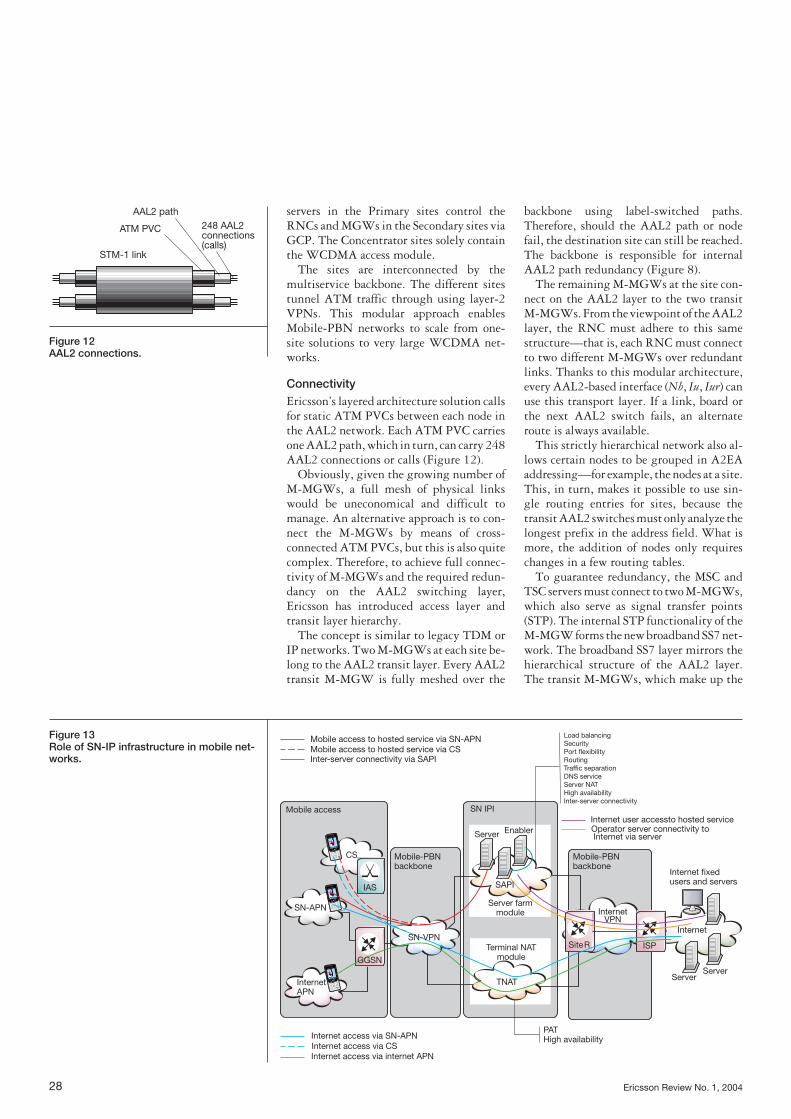
IP infrastructure of theservice network The service network framework (SNF) is anarchitectural framework that consists ofreusable designs for products and solutionsin the service layer.3 This includes the IPnetwork used for deploying the service net-work.
The SNF deployment view providesguidelines for ensuring that the IP networkcontains a set of common services and qual-ities on which every deployed system canrely. Examples of common services includenaming, addressing, routing, load-balancing, firewall, and security gatewayservices. Common qualities include perfor-mance, scalability, flexibility, security andhigh availability. The Mobile-PBN thusemploys a service network IP infrastructure(SN-IPI) that gives users of the Mobile In-ternet access to services hosted at the serverfarm, and mobile users access to the Inter-net.
The SN-IPI introduces two functionalmodules: the server farm module and theterminal NAT module. The server farmmodule provides services to mobile and In-
ternet users. It contains the service accessand protection infrastructure (SAPI), serviceenablers, and application servers located inthe mobile operator’s service network. Theterminal NAT modules provide the net-work address translation (NAT) functional-ity needed to map a private address to a pub-lic IP address when mobile subscribers wantto access the Internet. As seen in Figure 13,the Mobile-PBN backbone makes use ofSN-IPI modules and IP transport services toaccommodate several traffic flows.
Server farm modules In the context of the SN-IPI, the main sys-tem in a server farm module is the SAPI (Fig-ure 14). The other systems of the server farm(enablers, application and content servers)are integrated into the SAPI, which consistsof a set of firewalls placed between two pairsof load balancers—in this case, firewall loadbalancers (FWLB). This setup ensures in-cremental scalability. In other words, oper-ators can add more firewall protection as ca-pacity increases. The internal load balancers(iLB) also serve as load balancers for serversthat scale horizontally. L2/L3 switches areused to provide flexible, high-port densityto connect all enablers and services. Figure14 shows how these components are inter-connected.
Apart from providing physical connec-tivity and protecting servers, the SAPI also
GE
eLB iLB L2/L3 switch
eLB iLBL2/L3 switch
FE
FW
FW
GE
Servers
FE
GE
Active Active
StandbyStandby
Routing toward BB site routers Load balancing toward FW pool
Server load balancing
Mobile-PBN backbone
Internet
LB SLBFWLB FWLB
Mobile fleet
Active
Firewall sandwich
SAPI (Service access and protection infrastructure)
Connectivity to BB
Active
Figure 14 Service access and protection infrastruc-ture.

provides address translation—it supportsone-to-one and many-to-one address trans-lation.
A small package solution is offered forsmaller deployments of server farm mod-ules. The module replaces external load bal-ancers with standard L2/L3 switches. Thereare two variants for the internal server side.The first includes internal load-balancerunits, used only as server load balancers andnot as firewall load balancers. If necessary,standard L2/L3 switches can also be used toincrease the number of ports or to connectto certain nodes, such as those that are basedon TSP. The second variant includes inter-nal load balancers. This solution is provid-ed for operators who do not need load-balancing functionality.
The Mobile-PBN also provides supportfor integrating the following enablers andapplication servers into SAPI: USIS 1.0,DNS IPWorks 4.1, HTTP/FTP proxy(proxy + SSL), EMA 3.2, SNOS 1.0, MIEP2.0 and MMS 3.0.
Terminal NAT module The terminal NAT module consists of twoswitches that serve as NAT devices in an active-standby mode—if one of them fails,the other automatically takes over. In termsof deployment, the terminal NAT function-ality is distributed in the same way as Inter-net point of presence (PoP). Ideally, a NAT
module should be deployed near the point ofpresence (PoP). This reduces the mobile op-erator’s transmission costs by delivering traf-fic to the Internet as soon as possible.
Verification of the Mobile-PBN solution Although the integration of new equip-ment and features is a critical issue in mod-ern telecommunications networks, allplanned and unplanned downtime disturbsactive traffic and decreases revenue. Toshorten integration times, the Mobile-PBN verifies the basic and new aspects ofeach design module before the design canbe released.
The Mobile-PBN solution is set up andtested inside an end-to-end environment.The Ericsson Eurolab Deutschland GmbHverification center and the Ericsson AB Hot-Lab have several interconnected labs thatprovide the basic infrastructure for inte-grating every piece of equipment—siterouters, switches, firewalls, and load bal-ancers—with core network nodes (SGSN,GGSN, MSC, and M-MGW).
The modularity, flexibility and scalabili-ty of the Mobile-PBN are vital features forverification in the end-to-end test networks.These network characteristics ease the inte-gration of a customized solution into an ex-isting customer network.
30 Ericsson Review No. 1, 2004
• Connectivity and integration • Security • Resilience/redundancy• Quality of service traffic management • Operation and maintenance • Load and characteristics • Service network integration and the ser-
vice network IP infrastructure with serverfarm and terminal NAT
• Data optimization• Flexible bearer charging• Small network (single-site solution)• Network synchronization
TABLE 1, VERIFICATION ACTIVITIESCOVERED BY THE MOBILE-PBNSOLUTION

Ericsson Review No. 1, 2004 31
Test cases are defined to expose potentialproblems and to verify design concepts be-fore they reach the field. Verification re-veals different kinds of faults or unexpect-ed behavior in the equipment and networkconfiguration. Because the network is op-erational, the test cases also show how itcan be tuned for optimum performance.Traffic simulators and automated test pat-terns are used to simulate real radio net-work loading based on Ericsson’s experi-ence. These are used to stress the networkto ensure correct behavior under load,which is essential for verifying operation ofQoS delivery. Trouble Reports are writtenon all Ericsson and partner products. Allproblems and solutions are documented intest reports.
By discovering and resolving faults andunexpected effects, Ericsson makes the Mobile-PBN a more reliable network solu-tion for the end-customer. Table 1 lists thetest areas and extent of the Mobile-PBN ver-ification activities.
Conclusion This article demonstrates the strength ofEricsson’s Mobile-PBN modular designconcept: • functional modules such as the circuit-
switched (layered architecture) and service-network modules, can easily be
plugged into the transport modules (multiservice backbone and site infra-structure);
• other modules can be added easily whenneeded;
• the evolution of the backbone and site in-frastructure is optimally aligned with thetransport needs of the core network nodes(circuit- and packet-switched) and newpacket-based services; and
• the network can readily be expandedusing larger modules or adding new ones.
The design uses methods that cover a widerange of interconnected network areas andprovide the following network-wide attrib-utes:• strong security at every level;• class-of-service (CoS) differentiation;• high availability (through physical and
logical redundancy mechanisms);• traffic separation (allowing overlapping
IP address ranges for connected corpora-tions); and
• intra- and inter-site connectivity.A backbone and site infrastructure networkdesign based on Ericsson’s verified Mobile-PBN solution provides operators with manyadvantages—not only in terms of reducedcosts and minimized risks, but also in termsof network interoperability, scalability andmigration. With this solid foundation, op-erators can concentrate on providing attrac-tive and cost-effective end-user services.
1. The importance of network synchroniza-tion—Stand-alone products that supportthe design of synchronization networks,Ericsson Review no. 1, 2004
2. AAL2 switching in the WCDMA radioaccess network, Ericsson Review no. 3,2002
3. The service network framework—Anarchitectural blueprint for the service net-work, Ericsson Review no. 1, 2003
4. IP technology in WCDMA/GSM core net-works, Ericsson Review no. 1, 2002
REFERENCES