motion controllers ensemble drive-based
TRANSCRIPT

www.aerotech.com
— P R O D U C T H I G H L I G H T S —
Drive-based motion controller - part of the Ensemble platform
Powerful controller operates side-by-side on a motor drive, eliminating the need for additional hardware
Connects to and synchronizes the motion trajectory and I/O of up to 10 drives over the AeroNet digital motion bus
Multiple 10-axis systems can be controlled by a single PC via Ethernet or USB
Delivers productivity and quality through combined motion and process control
Executes real-time application code developed in the Ensemble Motion Composer Suite
Directly programmable through the .NET, C, C++, MATLAB, and LabVIEW libraries
Controller data is accessible to SCADA and MES control systems via libraries
Power and Flexibility in a Drive-Based Controller
The power of the Ensemble drive-based motion controller comes from both its powerful features and its flexibility.
The Ensemble controller is powerful. We develop our own controller technology from the ground up, allowing us to deliver an automation product that is centered around precision. This approach gives our products a new level of performance, especially when compared to products from other automation providers.
The Ensemble’s multi-axis coordination and precision often provide a new and rewarding experience for those used to coordinating several single-axis drives from a central processor (such as a PLC).
By using the multi-axis Ensemble controller while programming in the AeroBasic language, unique multi-axis functionality and performance is available, and this is very meaningful to the control of your machine.
The Ensemble controller executes programs that include Aerotech’s Position Synchronized Output (PSO) distance-based
process triggering, gearing, advanced data collection, file access, analog and digital I/O control, as well as standard program flow and mathematical concepts.
Powerful servo control on the Ensemble can be executed at up to 20 kHz and this power is deployed with flexibility. The Ensemble is powerful enough to take on complete machine control. It can also live as an embedded motion controller, subservient to a higher level machine controller. Combined with powerful software tools, the Ensemble controller excels in simple testing and development motion control applications and is robust enough for production environments.
Powerful Multi-Axis Trajectory Generation
At the heart of the controller is the ability to translate commands into the industry’s best trajectory. Our controller includes the Aerotech motion engine — a powerful piece of technology that differentiates Aerotech control from other motion providers. This technology translates your program into a multi-axis, synchronized, and coordinated trajectory that is sent out over the AeroNet Ethernet bus.
The AeroNet bus connects the Ensemble controller to up to
M O T I O N C O N T R O L L E R S E N S E M B L E D R I V E - B A S E D
www.aerotech.com
M O T I O N C O N T R O L L E R S | E N S E M B L E D R I V E - B A S E D
10 axes of motion control. Servomotors, piezos, voice coil, and stepper motor drive hardware can be connected on the AeroNet bus.
Advanced trajectory features include:
• Point-to-point (PT, PV, PVT)
• Target position and target velocity
• Linear, circular, and freerun
• Digital gearing with optional auxiliary encoder input
• Cubic spline curve-fitting
• Velocity profiling
• Backlash compensation
• 1D and 2D error compensation
• Advanced queuing and deferred execution features for simultaneous command execution
Motion Plus Animation
Modern machines do more than move a process tool. Many sensors and feedback devices need to come together in a larger control scheme.
The Ensemble controller, which runs on motor drive hardware, contains expandable I/O. The controller also connects to several other drives with expandable I/O. A simple four-axis Ensemble solution could have over 200 I/O points. Using the AeroBasic language, logic and control algorithms are easily programmed based on the state of I/O.
Ethernet and RS-232 Support
Ensemble drive hardware includes both Ethernet and RS-232 communication ports. These ports allow greater expandability of your automation solution — beyond the I/O available on the drives.
Modbus
The Ethernet port is configurable for Modbus communications. Class 1, Class 2, and part of Class 3 of the OpenModbus/TCP specifications are supported. While the Ensemble always functions as Modbus/TCP slave, it can also act as a Modbus/TCP master when enabled, thus acting as a master and slave at the same time. Several blocks of Modbus registers are used to exchange data between the master and slave devices.
Aerotech includes standard procedures in its help files for integrating both WAGO and AutomationDirect devices over Modbus.
EtherNet/IP
Aerotech offers an Ensemble EtherNet/IP™ option that communicates with Aerotech Ensemble drives and the various ODVA Common Industrial Protocol (CIP™) objects that are used. The Ensemble supports a Generic EtherNet/IP I/O interface by using Class 1 (implicit messaging) communications.
EPICS Compatible
Aerotech’s Ensemble controller is compatible with EPICS. Motor records are available from Argonne National Lab. Use your existing EPICS interface to control the most advanced motion controller in the industry.
TANGO Compatible
Aerotech’s Ensemble controller is compatible with TANGO environments. The TANGO Device Server is available on Sourceforge.net. Use the industry’s most advanced motion controller in your existing TANGO environment.
Flexible, High-Performance System Architecture
Our controller enables high performance by managing a distributed control architecture. Whereas centralized control architectures close the servo and current loops on a central controller, the Ensemble Platform closes the position, velocity, and current loops on each individual Ensemble drive, avoiding processing bottlenecks. Trajectory generation is done on a single drive. This controller executes programs and sends the position commands to the Ensemble drives via the AeroNet network.
Motion Composer Suite Engineering Software
Aerotech’s Ensemble Motion Composer Suite is a feature-rich engineering software package. This software allows each member of your design team to contribute in setting up the controller and motion to your application’s requirements.
Simply connect to the controller using the Motion Composer Suite. Then use several user-friendly tools to set up each control loop on each drive and also set up controller-specific parameters.
Programming for Performance
The Ensemble Motion Composer Suite includes the Motion Composer IDE — a feature-rich programming environment for developing real-time application code. The Motion Composer IDE allows you to quickly build, debug, load, and run real-time application code on the controller.
Programming Libraries Extend Functionality
When your goal is to deploy a custom user experience or access data from your drive, the Ensemble controller enables many paths to success. Standard programming libraries for .NET, C, and C++ are included with the controller. A simple REST web interface is also included.
If you are developing MATLAB or LabVIEW applications, support for each product is available.
No matter how you want to approach your precision motion control application, the Ensemble controller helps you to succeed.
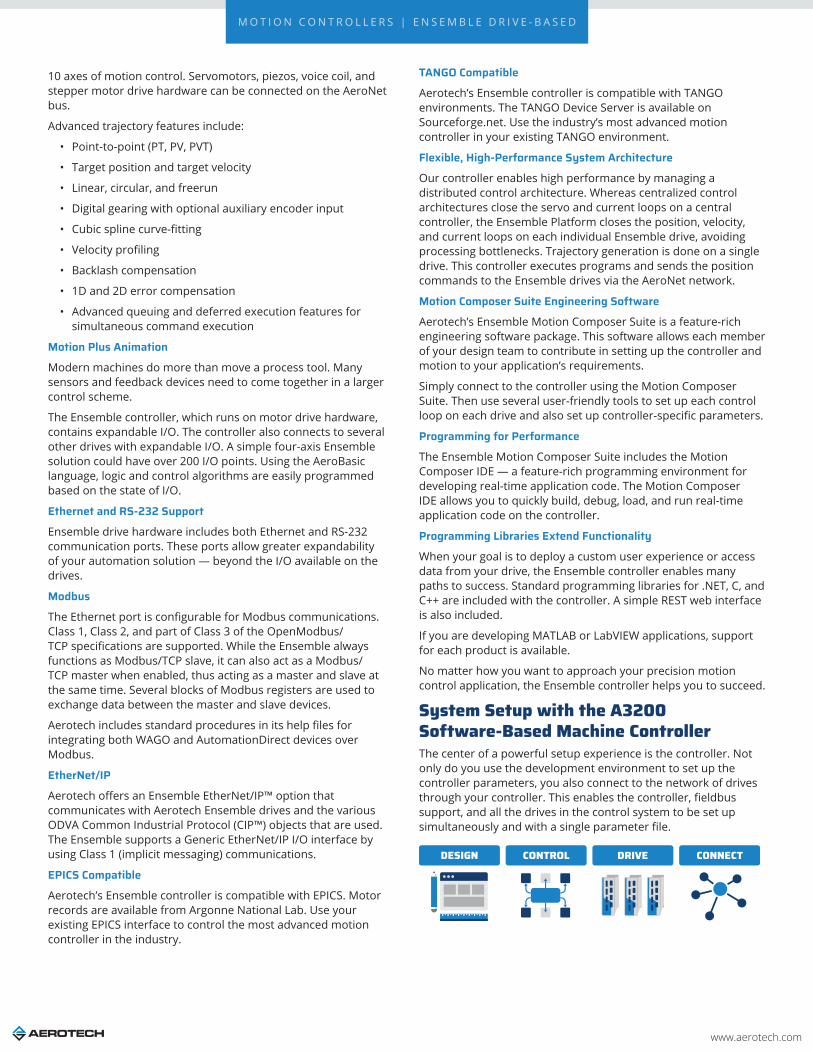
System Setup with the A3200 Software-Based Machine ControllerThe center of a powerful setup experience is the controller. Not only do you use the development environment to set up the controller parameters, you also connect to the network of drives through your controller. This enables the controller, fieldbus support, and all the drives in the control system to be set up simultaneously and with a single parameter file.
DESIGN CONTROL DRIVE CONNECT

www.aerotech.com
M O T I O N C O N T R O L L E R S | E N S E M B L E D R I V E - B A S E D
Programming Libraries.NET, C, and C++ Libraries Plus REST Interface
Aerotech’s standard controllers are flexible enough to handle almost any control application. From simple motion to coordinating and synchronizing the motion of multiple axes in your machine, Aerotech automation controllers provide the flexibility and power required for today’s automation challenges, and it is all accessible through powerful programming libraries.
MATLAB® Library and LabVIEW® VIs
Users who program in MATLAB and LabVIEW can benefit from Aerotech’s powerful automation tools. Integrate into your native environment with well-documented libraries.
.NET Library – Fully Functional for Developers
The Ensemble .NET library is made accessible to our customers in the same structure and format that we use to develop our own applications. Therefore, developers should never worry that using our API will somehow reduce the capabilities of their own products or developments.
Some of the high-level functionality available in our APIs include:
Accessing Data with the Ensemble Drive-Based Motion ControllerAccessing data from your controller is simple. The Ensemble controller allows fast and easy access to data: through both the Ensemble Motion Composer Suite and through the APIs.
Through the Motion Composer Suite
More than 30 axis status items are available for each controller axis, and 10 task state items are available for each controller task.
Through the API
These same signals are available for collection and analysis through industry-standard tools using the programming APIs.
Functionality DescriptionConnect Connect to one or several controllers
ConfigureConfigure settings, set/retrieve controller and drive parameters, tune motors and encoders, and load
drive firmware
Execute Commands Execute AeroBasic commands in .NET
Program Files
Compile AeroBasic programs, get build errors, load and run AeroBasic programs on the controller,
and handle the controller tasks that run AeroBasic programs
Communicate Setup and command drive and controller communication ports and protocols
Monitor Status Get status and monitor information coming from the controller
Collect Data Collect data on the controller in real time; exposes functionality used by the Digital Scope
www.aerotech.com
M O T I O N C O N T R O L L E R S | E N S E M B L E D R I V E - B A S E D
Point-to-Point Motion Acceleration Limiting
Y
X
C D
E
F
B
A
H G
Coordinated Motion Arbitrary Path Generation (PVT)
Electronic Gearing On the Fly End-Point Modification Velocity Profiling Seven Segment Acceleration
X
V
Velocity Blending Fast Position Capture High-Speed Registration Gantry Mode
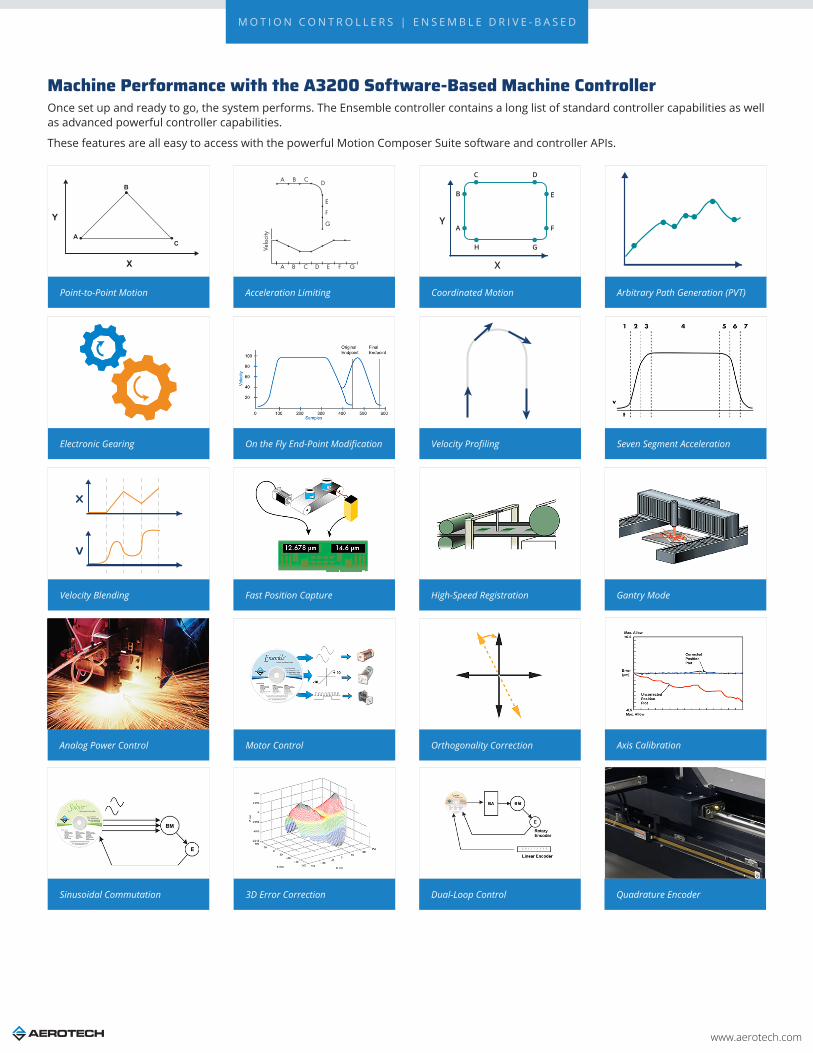
Machine Performance with the A3200 Software-Based Machine ControllerOnce set up and ready to go, the system performs. The Ensemble controller contains a long list of standard controller capabilities as well as advanced powerful controller capabilities.
These features are all easy to access with the powerful Motion Composer Suite software and controller APIs.
Analog Power Control Motor Control Orthogonality Correction Axis Calibration
Sinusoidal Commutation 3D Error Correction Dual-Loop Control Quadrature Encoder

www.aerotech.com
M O T I O N C O N T R O L L E R S | E N S E M B L E D R I V E - B A S E D
Analog Feedback Resolver/Inductosyn Laser Interferometer Encoder
Tachometer PIDFF Limits CAM Profiling
Harmonic Cancellation
K1K2
Dynamic Gain Scheduling Command Shaping Position Synchronized Output (PSO)
EasyTune Iterative Learning Control Gantry Control Enhanced Throughput Module
Motion Designer Enhanced Tracking Control

www.aerotech.com
M O T I O N C O N T R O L L E R S | E N S E M B L E D R I V E - B A S E D
Ensemble Drive-Based Motion Controller Specifications
Specification DescriptionAxes 10 axes available
Programming Tasks 5 tasks available
Position Modes Absolute, incremental, dynamic trajectory correction
Coordinated Motion Types
Coordinated Synchronous MotionCoordinated motion refers to moves that follow a well-defined path in space. Coordinated moves start and stop axes at the same time. They can execute in velocity profiling mode.
• Linear motion• Clockwise and counterclockwise• Bezier• Cubic-spline curve fitting
CNC Option: RS-274 standard G-code motion including linear, circular, helical, and spherical interpolation, cutter compensation, normalcy, parts rotation, mirroring, path retrace, polar transformations and cylindrical transformations, scaling.
Independent Motion Types
Non-Coordinated Synchronous MotionNon-coordinated motion refers to moves in which axes start at the same time but do not necessarily end at the same time. Each axis moves at its own velocity specified in the command or by axis parameters. Program execution does not continue to the next line until all axes in the move command have completed motion.
HomingMultiple procedures are available in order to establish the home position of an axis:
• Home past limit switch to home marker• Home to limit switch and reverse to home marker• Home to home marker• Home to limit switch• Home at current position and set to zero• Home at current position and set to absolute position
Asynchronous MotionAsynchronous motion commands cause program execution to continue on to the next program block immediately after the move starts. The controller does not wait for the move to end before continuing to the next command.
• Home an axis without waiting for completion• Free-run an axis at the specified velocity• Move to an absolute position• Move incrementally• Move an axis out of a limit condition• Move an axis into a limit condition• Oscillate (cycle at the specified distance and velocity)• Debug Motion:
• Output a fixed current to the specified axis (use only with brushless motors)• Output the specified electrical vector to the specified axis, typically for resolver or Hall effect
device alignment
Planes and Tasks
In the Ensemble, there are programmable planes such that multiple tasks can use the same queue. It can also be configured so that tasks can use different queues — either as a way of separating axis groups by task, or as a way to generate simultaneous motion on the same axes from different tasks.
• Plane: a coordinate system and motion queue• Task: a space in which a program is executed. • Queue: a lineup of motion commands waiting in order to be executed
Why use Planes?• Synchronization: synchronize the motion between two user tasks, such as executing two linear moves
from two different tasks. Using the same plane for motion in both tasks ensures that one motion segment will finish before the next starts.
• Axis Separation: Multiple planes can be used to separate motion on different axes so that the axes can be run simultaneously.
• Cumulative Motion: Multiple planes can also be used to create motion on the same axes from different user tasks and combine the motion profiles to form the axis position.
Acceleration Profiles
• S-curve: Trapezoidal acceleration applied resulting in an “s-curve” velocity profile • SCURVE = 0: a constant acceleration applied resulting in linear velocity profile• SCURVE between 0 and 99: a trapezoidal acceleration applied resulting in an “s-curve” velocity profile• SCURVE = 100: a triangular acceleration applied resulting in an “s-curve” velocity profile
Acceleration Modes• Time based: axis acceleration takes place over a specified time• Rate based: axis acceleration takes place at a specified rate• Distance based: axis acceleration takes place over a specified distance

www.aerotech.com
M O T I O N C O N T R O L L E R S | E N S E M B L E D R I V E - B A S E D
Velocity Profiling
Blend multiple coordinated motion commands into one continuous motion path. In this velocity profiling mode, the controller does not decelerate to zero between consecutive coordinated moves. During the move sequence you can change the velocity if necessary. The axes will increase or decrease in speed in a coordinated way such that the programming path is maintained.
Without Velocity Profiling With Velocity Profiling
Advanced Features
• High-speed registration• Multi-dimensional error mapping• Orthogonality correction• Electronic gearing (with optional auxiliary encoder input)• EasyTune and Autotuning• Backlash compensation• Autofocus• Gantry algorithms
Programming
• AeroBasic• C++/CLI, C • .NET• LabVIEW®
• MATLAB®
Ensemble Software License SpecificationsOption Configuration Description
Ensemble Order Entry Point
Full installation of the Ensemble Motion Composer Suite and unlocks certain features on the Ensemble drive-based controllers
Pricing is summation of selected products. Maintenance (software update) included in price for one year from date of purchase.
The Ensemble Motion Composer Suite is intended for deployment on desktop or industrial PCs
Includes:• Ensemble Configuration Manager• Ensemble Motion Composer IDE• Ensemble Digital Scope• Ensemble Console• Ensemble Firmware Loader• Ensemble Help • Programming Help
The Ensemble is not multilingual and cannot be used in applications that require a native-language user interface
License
Machine
Contains both the Ensemble Motion Composer Suite and options thatenable features on an Ensemble Drive-Based Controller
Provides the ability to:• Write, compile, execute, debug programs in AeroBasic• Full access to .NET, C, and C++ libraries• Access full diagnostics, fault, and status information• Access and set I/O, registers, and variables • Collect, analyze, and save data• View files from machine for analysis and record keeping• Connect PC to machine through Ethernet TCP/IP or USB• Upgrades can be installed (firmware or controller) using loader
Machine Upgrade
• Use to change configuration options on an existing machine license• Requires the current license ID from customer• Price is based on the new options added• Maintenance extension is a separate line item
Machine Addition Increases the number of licenses associated with an existing key
License Extension • Extends the maintenance period on an existing license • Can be purchased in yearly increments
Media Only License ID distributed on the specified media
www.aerotech.com
M O T I O N C O N T R O L L E R S | E N S E M B L E D R I V E - B A S E D
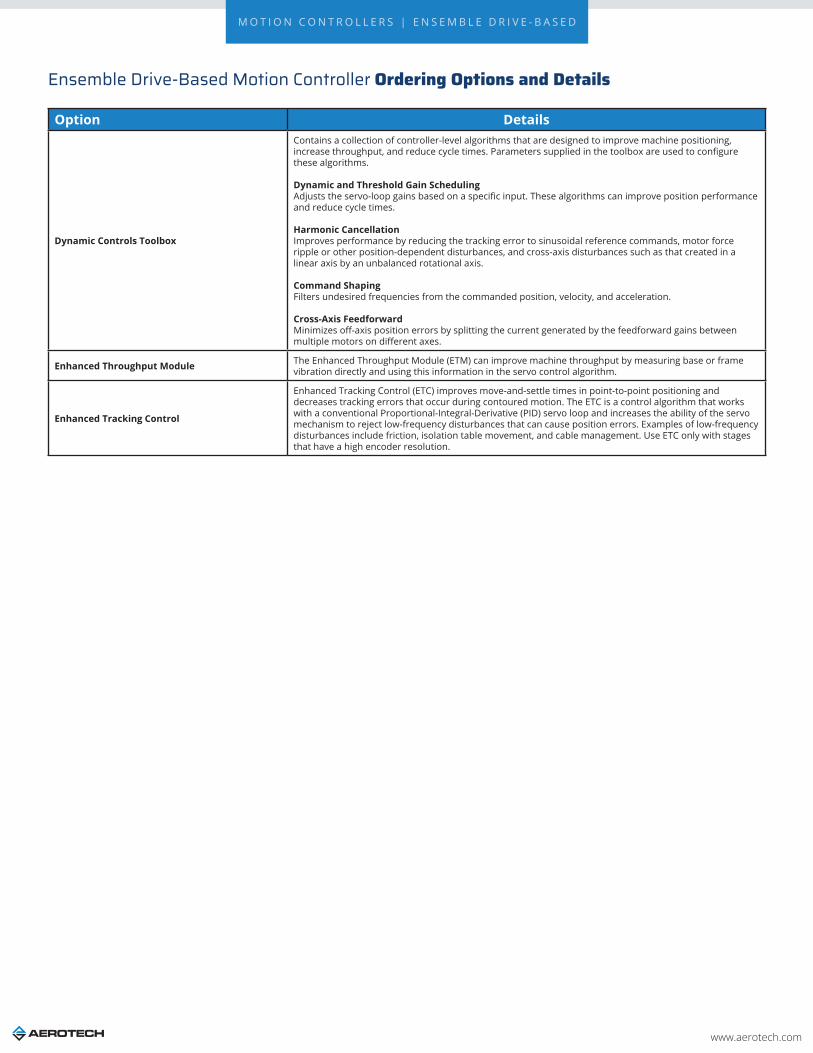
Ensemble Drive-Based Motion Controller Ordering Options and Details
Option Details
Dynamic Controls Toolbox
Contains a collection of controller-level algorithms that are designed to improve machine positioning, increase throughput, and reduce cycle times. Parameters supplied in the toolbox are used to configure these algorithms.
Dynamic and Threshold Gain SchedulingAdjusts the servo-loop gains based on a specific input. These algorithms can improve position performance and reduce cycle times.
Harmonic Cancellation Improves performance by reducing the tracking error to sinusoidal reference commands, motor force ripple or other position-dependent disturbances, and cross-axis disturbances such as that created in a linear axis by an unbalanced rotational axis.
Command Shaping Filters undesired frequencies from the commanded position, velocity, and acceleration.
Cross-Axis Feedforward Minimizes off-axis position errors by splitting the current generated by the feedforward gains between multiple motors on different axes.
Enhanced Throughput Module The Enhanced Throughput Module (ETM) can improve machine throughput by measuring base or frame vibration directly and using this information in the servo control algorithm.
Enhanced Tracking Control
Enhanced Tracking Control (ETC) improves move-and-settle times in point-to-point positioning and decreases tracking errors that occur during contoured motion. The ETC is a control algorithm that works with a conventional Proportional-Integral-Derivative (PID) servo loop and increases the ability of the servo mechanism to reject low-frequency disturbances that can cause position errors. Examples of low-frequency disturbances include friction, isolation table movement, and cable management. Use ETC only with stages that have a high encoder resolution.

www.aerotech.com
M O T I O N C O N T R O L L E R S | E N S E M B L E D R I V E - B A S E D
Allen-Bradley EtherNet/IP Interface to Aerotech EnsembleThe Aerotech Ethernet/IP interface enables AB PLCs (MicroLogix, CompactLogix, and ControlLogix) to integrate directly with the Ensemble motion control solutions. Motion can be directly programmed in the RSLogix 5000 environment or separate programs can be written on the controller and triggered from the AB PLC. Aerotech has two Ethernet/IP interfaces: ASCII and Register. Choose the PLC, motion controller, and Ethernet/IP interface that best fits your application needs.
The Allen-Bradley code snippets provided here are written in the graphical “relay ladder logic” syntax. Allen-Bradley also supports function block and structured text programming languages.
ASCII Command Interface
The ASCII command interface can be used to send ASCII text strings to the Ensemble and perform a set of actions such as commanding motion or retrieving diagnostic information. Our vendor-specific EtherNet/IP ASCII command interface object extends this functionality across EtherNet/IP.
The power of the ASCII command interface lies in its simplicity and ease of use. A text string is formed using an AeroBASIC™ command, followed by an End-Of-String (EOS) character. ASCII response data indicates whether or not the command was successfully executed. An ACK character is sent to indicate success, an NAK character is sent if there is a command error, and a FAULT character is sent if there is a task error. For commands that expect return data, the response character is followed by the return data, which is terminated by the EOS character. The EOS, ACK, NAK, and FAULT characters are configurable via Ensemble drive parameters.
To send the ASCII command from the PLC (programmed using Rockwell RSLogix) to the Ensemble, an MSG block is used (Figure 1). The EtherNet/IP message can be easily configured from within the RSLogix software as shown in Figure 2.
Figure 1. Allen-Bradley code snippet (Ladder Logic) for ASCII interface.
Figure 2. The value of the RSLogix tag in the red box will be sent to the Ensemble.
ASCII_Text_String (specified in the red box in Figure 2) is an RSLogix “tag”. The value of this tag is the ASCII command that will be sent to the Ensemble. The example in Figure 3 shows the command “HOME X Y” as it would be configured in RSLogix.
When the MSG block is activated, the ASCII command is sent to the Ensemble via the EtherNet/IP protocol. The Destination field of the message configuration can be used to specify a local tag for the ASCII command’s return data.
Ensemble Code Snippet (AeroBASIC) for ASCII Interface
For this interface (see Figure 4), the user does not need to write any AeroBASIC code on the Ensemble. The Ensemble automatically receives and processes the commands. This functionality is built into our EtherNet/IP module.
Register Interface
Our vendor-specific EtherNet/IP register interface object allows the Ensemble’s built-in integer and double registers to be accessed via EtherNet/IP. This provides a flexible, general-purpose interface to the Ensemble that can be adapted to many different applications. Data consistency is guaranteed internally, so there is no need for concern when accessing these registers simultaneously via EtherNet/IP and AeroBASIC programs on the controller.
The Rockwell software is configured in very much the same way as the ASCII command interface. In this case, the message source (shown in red in Figure 5) is a data array. The message configuration in Figure 5 is for the “Write Single Register” service. That service requires two pieces of data: the number of the register to write, and the value to be written. Therefore, we configure the message source tag as shown in Figure 6.
Figure 3. “HOME X Y” as it would be configured in RSLogix.
Figure 4. Allen-Bradley code snippet (Ladder Logic) for Register interface.
Figure 5. Allen-Bradley code snippet (Ladder Logic) for Register interface.

www.aerotech.com
M O T I O N C O N T R O L L E R S | E N S E M B L E D R I V E - B A S E D
The value 100 is the register to write to, and the value to be written is 7. When the MSG block is activated, the register query is sent to the Ensemble via the EtherNet/IP protocol.
As you can see, this is a straightforward data interface from the PLC to the Ensemble. In addition to writing a single register, the interface also supports writing multiple registers in one message and reading single or multiple registers. This example was interfacing with an integer (32-bit) register, but the interface supports the same functionality with double-precision (64-bit) floating point values.
Ensemble Code Snippet (AeroBASIC) for Register Interface
To make use of the data that is being transferred to and from the PLC, the user can write an AeroBASIC program to respond to incoming register transfers, as well as write outbound register data. This combination of EtherNet/IP communication with the power and flexibility of AeroBASIC allows for the implementation of many unique applications. For example, the following AeroBASIC code snippet shows how the register interface can be used to control the Ensemble timebase value (set by the AeroBASIC TimeScale command).
HEADER ‘ The PLC writes timebase values to IntegerRegister 101 Define timebaseRegisterIndex 101 END HEADER
DECLARATIONS ‘ Declare a global variable named “timebase” Global timebase as Integer END DECLARATIONS
PROGRAM ‘ initialize the timebase register to 100% speed RegS IntegerRegisters, timebaseRegisterIndex, 100 ‘ ... do work in AeroBASIC ... ‘ Change timebase to value sent from PLC Call GetTimebase() TimeScale timebase ‘ ... continue working ... END PROGRAM
FUNCTION GetTimebase() as void ‘ Read the value from IntegerRegister 101 into the variable “timebase” timebase = RegS(IntegerRegisters, timebaseRegisterIndex) END FUNCTION
Figure 6. Allen-Bradley code snippet (Ladder Logic) for Register interface.

www.aerotech.com
M O T I O N C O N T R O L L E R S | E N S E M B L E D R I V E - B A S E D
Ensemble Drive-Based Motion Controller Ordering Information
EnsembleEnsemble Ensemble Motion Composer Suite
License Options
License-Machine Ensemble software installation on a single PC -Machine upgrade Ensemble software configuration change of license-Machine addition Ensemble software increase license count for existing key-License extension Ensemble software extend maintenance period of license-Media only Ensemble software distribute current license on media
Media-Download Installation media provided for download only-USB Installation media provided on a USB drive-CD Installation media provided on compact disk
Version-Default Current version of software/controller-Legacy Legacy version of software/controller
Maintenance-Maintenance-X-00 Software/controller maintenance for x year(s) after purchase where X is one through seven. One year is default.
Software-Based Controller Configuration
Dynamic Controls Toolbox-Dynamic Controls Toolbox Aerotech Advanced Controls
Enhanced Throughput Module-Enhanced Throughput Module Setup and monitoring screens for ETM modules
Enhanced Tracking Control-Enhanced Tracking Control Reduced dynamic following error and settling times
Five Axes Contouring-Five Axes Contouring More than 4 axes of coordinated motion with a single motion command. Note: Old part number: CNC-5
EtherNet/IP-EtherNet/IP EtherNet/IP class 1 I/O, ASCII command, and register interface objects
Motion Designer-Motion Designer Trajectory creation and evaluation software
LabVIEW-LabVIEW Includes LabVIEW 2010 (forward compatible) VI samples
MATLAB Libraries-MATLAB MATLAB library for motion, parameters, and data collection
Ensemble Controller Connection Cable (Items Ordered Separately)
PC to Ensemble Drive/Controller CableENET-XOVER-xx Ethernet crossover cable (available in length xx where xx = 9, 15, 30, 45, 60, 75, or 150 dm)USB-AMBM-xx USB A-Male to B-Male cable (available in length xx where xx = 5, 10, 30, 50, or 200 dm)
-MATLAB MATLAB library for motion, parameters and data collection
AeroNet Communication Network (Items Ordered Separately)
Ensemble Drive-to-Drive CableENET-CAT6-xx Shielded Ethernet CAT6 cable (available in length xx where xx = 3, 6, 10, 20, 30, 45, 76, or 90 dm)

www.aerotech.com
M O T I O N C O N T R O L L E R S | E N S E M B L E D R I V E - B A S E D
Remote Server-Remote Configure A3200 as server
Motion Composer Suite Add-Ons
CNC Operator Interface-CNC Operator Interface HMI CNC software for Windows. Includes the CNC option.
Motion Designer-Motion Designer Trajectory creation and evaluation software
Motion Simulator-Motion Simulator Trajectory simulation, creation, and evaluation software
LabVIEW-LabVIEW Includes LabVIEW 2010 (forward compatible) VI samples
MATLAB Libraries-MATLAB MATLAB library for motion, parameters and data collection
FireWire Communication Network (Items Ordered Separately)
NFire-PCIeNFire-PCIe FireWire communication network PCIe card (recommended)
NFire-PCINFire-PCI FireWire communication network PCI card
NConnect-6P6P-xx*NConnect-6P6P-45 FireWire cable (4.50 meter length), 6P to 6PNConnect-6P6P-30 FireWire cable (3.00 meter length), 6P to 6PNConnect-6P6P-18 FireWire cable (1.80 meter length), 6P to 6PNConnect-6P6P-9 FireWire cable (0.90 meter length), 6P to 6PNConnect-6P6P-5 FireWire cable (0.50 meter length), 6P to 6PNConnect-6P6P-2.3 FireWire cable (0.23 meter length), 6P to 6P*Note: Aerotech strongly recommends the use of FireWire cables supplied by Aerotech (NCONNECT cables). These cables are tested to ensure proper performance. A single open PCI or PCIe card slot is required to accommodate the required FireWire PCI or PCIe card for Aerotech’s motion bus.
HyperWire Communication Network (Items Ordered Separately)
HyperWire-PCIeNFire-PCIe Firewire communication network PCIe card (recommended)
HyperWire-AO10-xxHyperWire-AO10-200 HyperWire cable (20.0 meter length), SFP to SFPHyperWire-AO10-50 HyperWire cable (5.0 meter length), SFP to SFPHyperWire-AO10-30 HyperWire cable (3.0 meter length), SFP to SFPHyperWire-AO10-10 HyperWire cable (1.0 meter length), SFP to SFPHyperWire-AO10-5 HyperWire cable (0.5 meter length), SFP to SFP