motoman nx100 controller robotic arc welding manual€¦ · the fronius welding system is an...
TRANSCRIPT

Motoman, Incorporated 805 Liberty LaneWest Carrollton, OH 45449TEL: (937) 847-6200FAX: (937) 847-627724-Hour Service Hotline: (937) 847-3200
Motoman NX100 Controller
Robotic Arc Welding Manualfor Fronius Power Sources
Part Number: 148881-2CDRevision 0

COMPLETE OUR ONLINE SURVEYMotoman is committed to total customer satisfaction! Please give us your feedback on the technical manuals you
received with your Motoman robotic solution.
To participate, go to the following website:
http://www.motoman.com/forms/techpubs.asp
The information contained within this document is the proprietary property of Motoman, Inc., and may not be copied, reproduced or transmitted to other parties without the expressed written authorization of Motoman,
Inc.
©2007 by MOTOMANAll Rights Reserved
Because we are constantly improving our products, we reserve the right to change specifications without notice. MOTOMAN is a registered trademark of YASKAWA Electric Manufacturing.

Robotic Arc Welding148881-2
Table of Contents
Chapter 1 Introduction . . . . . . . . . . . . . . . . . . . . . . . . . . . . . . . . . . . . . . . . . . . . . . . . . . . . . . . . . . . . . . . . . . 1
1.1 About This Document . . . . . . . . . . . . . . . . . . . . . . . . . . . . . . . . . . . . . . . . . . . . . . . . . . . . 11.2 System Configuration . . . . . . . . . . . . . . . . . . . . . . . . . . . . . . . . . . . . . . . . . . . . . . . . . . . . . 2
1.2.1 Major Components . . . . . . . . . . . . . . . . . . . . . . . . . . . . . . . . . . . . . . . . . . . . . . . . . . 31.3 Reference to Other Documentation . . . . . . . . . . . . . . . . . . . . . . . . . . . . . . . . . . . . . . . . . . 31.4 Customer Service Information . . . . . . . . . . . . . . . . . . . . . . . . . . . . . . . . . . . . . . . . . . . . . . 4
Chapter 2 Safety . . . . . . . . . . . . . . . . . . . . . . . . . . . . . . . . . . . . . . . . . . . . . . . . . . . . . . . . . . . . . . . . . . . . . . . 5
2.1 Introduction . . . . . . . . . . . . . . . . . . . . . . . . . . . . . . . . . . . . . . . . . . . . . . . . . . . . . . . . . . . . 52.2 Important Advisory Information . . . . . . . . . . . . . . . . . . . . . . . . . . . . . . . . . . . . . . . . . . . . . 62.3 General Safeguarding Tips . . . . . . . . . . . . . . . . . . . . . . . . . . . . . . . . . . . . . . . . . . . . . . . . . 62.4 Mechanical Safety Devices . . . . . . . . . . . . . . . . . . . . . . . . . . . . . . . . . . . . . . . . . . . . . . . . . 72.5 Installation Safety . . . . . . . . . . . . . . . . . . . . . . . . . . . . . . . . . . . . . . . . . . . . . . . . . . . . . . . . 72.6 Programming, Operation, and Maintenance Safety . . . . . . . . . . . . . . . . . . . . . . . . . . . . . . . 8
Chapter 3 Equipment Description. . . . . . . . . . . . . . . . . . . . . . . . . . . . . . . . . . . . . . . . . . . . . . . . . . . . . . . 11
3.1 Robot and Controller . . . . . . . . . . . . . . . . . . . . . . . . . . . . . . . . . . . . . . . . . . . . . . . . . . . . 113.2 Fronius Power Supplies . . . . . . . . . . . . . . . . . . . . . . . . . . . . . . . . . . . . . . . . . . . . . . . . . . . 11
3.2.1 Welding Circuit Resistance Measurement . . . . . . . . . . . . . . . . . . . . . . . . . . . . . . . . 123.2.2 Robacta Torch . . . . . . . . . . . . . . . . . . . . . . . . . . . . . . . . . . . . . . . . . . . . . . . . . . . . 123.2.3 Job Mode . . . . . . . . . . . . . . . . . . . . . . . . . . . . . . . . . . . . . . . . . . . . . . . . . . . . . . . . 123.2.4 PC Software . . . . . . . . . . . . . . . . . . . . . . . . . . . . . . . . . . . . . . . . . . . . . . . . . . . . . . 123.2.5 Synergic Control . . . . . . . . . . . . . . . . . . . . . . . . . . . . . . . . . . . . . . . . . . . . . . . . . . . 13
3.3 Fronius VR1500 Wire Feeder . . . . . . . . . . . . . . . . . . . . . . . . . . . . . . . . . . . . . . . . . . . . . . 133.4 ROB 5000 Interface . . . . . . . . . . . . . . . . . . . . . . . . . . . . . . . . . . . . . . . . . . . . . . . . . . . . . 143.5 Water Circulator . . . . . . . . . . . . . . . . . . . . . . . . . . . . . . . . . . . . . . . . . . . . . . . . . . . . . . . . 14
Chapter 4 Theory of Operation . . . . . . . . . . . . . . . . . . . . . . . . . . . . . . . . . . . . . . . . . . . . . . . . . . . . . . . . . 15
4.1 Gas Metal Arc Welding . . . . . . . . . . . . . . . . . . . . . . . . . . . . . . . . . . . . . . . . . . . . . . . . . . . 154.1.1 Short-Circuit Transfer . . . . . . . . . . . . . . . . . . . . . . . . . . . . . . . . . . . . . . . . . . . . . . . 164.1.2 Globular Transfer . . . . . . . . . . . . . . . . . . . . . . . . . . . . . . . . . . . . . . . . . . . . . . . . . . 164.1.3 Spray Transfer . . . . . . . . . . . . . . . . . . . . . . . . . . . . . . . . . . . . . . . . . . . . . . . . . . . . . 17
4.2 Pulsed Gas Metal Arc Welding . . . . . . . . . . . . . . . . . . . . . . . . . . . . . . . . . . . . . . . . . . . . . 17
Final i

System Manual Table of Contents
Chapter 5 Operation . . . . . . . . . . . . . . . . . . . . . . . . . . . . . . . . . . . . . . . . . . . . . . . . . . . . . . . . . . . . . . . . . . . 19
5.1 Local Control . . . . . . . . . . . . . . . . . . . . . . . . . . . . . . . . . . . . . . . . . . . . . . . . . . . . . . . . . . 205.2 Program (Schedule Select) Control . . . . . . . . . . . . . . . . . . . . . . . . . . . . . . . . . . . . . . . . . . 20
5.2.1 Robot Job Commands for Program Mode . . . . . . . . . . . . . . . . . . . . . . . . . . . . . . . 205.2.1.1 AON_FR . . . . . . . . . . . . . . . . . . . . . . . . . . . . . . . . . . . . . . . . . . . . . . . . . . . 205.2.1.2 ASET_FR . . . . . . . . . . . . . . . . . . . . . . . . . . . . . . . . . . . . . . . . . . . . . . . . . . . 225.2.1.3 FR_SET . . . . . . . . . . . . . . . . . . . . . . . . . . . . . . . . . . . . . . . . . . . . . . . . . . . . 23
5.3 Robot Controller-Power Supply Calibration . . . . . . . . . . . . . . . . . . . . . . . . . . . . . . . . . . . 245.3.1 AWELD = Wire Feed Speed . . . . . . . . . . . . . . . . . . . . . . . . . . . . . . . . . . . . . . . . . 255.3.2 AWELD = Amperage . . . . . . . . . . . . . . . . . . . . . . . . . . . . . . . . . . . . . . . . . . . . . . . 275.3.3 Verify Proper Calibration . . . . . . . . . . . . . . . . . . . . . . . . . . . . . . . . . . . . . . . . . . . . 28
5.4 Job Mode . . . . . . . . . . . . . . . . . . . . . . . . . . . . . . . . . . . . . . . . . . . . . . . . . . . . . . . . . . . . . 305.4.1 Robot Job Commands for Job Mode . . . . . . . . . . . . . . . . . . . . . . . . . . . . . . . . . . . 31
5.4.1.1 AON_FRJ . . . . . . . . . . . . . . . . . . . . . . . . . . . . . . . . . . . . . . . . . . . . . . . . . . 31
Index . . . . . . . . . . . . . . . . . . . . . . . . . . . . . . . . . . . . . . . . . . . . . . . . . . . . . . . . . . . . . . . . . . . . . . . 33
ii Final

Robotic Arc Welding148881-2
Chapter 1
Introduction
The Fronius TS (synergic, non-pulse) and TPS (synergic, pulse) power sources represent state-of-the-art technology in welding today. An interactive power source manager is coupled with a digital signal processor to control and regulate the entire welding process. Weld data is measured continuously, allowing the power source to respond immediately to any changes.
1.1 About This Document
This manual provides information about Motoman’s robotic arc welding system using the Fronius TS and TPS power sources. It is intended for welding personnel who have received operator training from Motoman, and are familiar with the operation of their Motoman robot model. For more detailed information, refer to the manuals listed in Section 1.3. This manual contains the following sections:SECTION 1 - INTRODUCTIONThis section provides general information about the Fronius power sources and their components, technical specifications, a list of reference documents, and customer service information.
SECTION 2 - SAFETYThis section describes the conventions used to identify precautionary text throughout this manual. This section also contains a list of general cautions and warnings that apply to many of the procedures described in this manual.
SECTION 3 - INSTALLATIONThis section provides instructions for basic setup and integration of the Fronius arc welding system. This section also provides procedures for start-up and calibration.
SECTION 4 - THEORY OF OPERATIONThis section describes general arc welding principles, how the welding system works, and identifies specific welding problems and requirements.
SECTION 5 - OPERATIONThis section provides instructions for basic operation of the Fronius arc welding system. This section also provides procedures for start-up. Sample robot programs are also included in this section.
Final 1

System Manual Chapter 1 Introduction
1.2 System Configuration
The Fronius welding system is an integrated package of tools and components designed for specific welding requirements. A typical system includes the following components and optional equipment.
Figure 1 Typical Fronius Welding System
SERVO
ON
READY
REMOTE
PLAY
(OFF)(ON
)
TEACH MOD
E
EMERGE
NCY ST
OP
EDIT L
OCK
ALARM
HOLDSTART
ON
TR
IP
OPEN/ROFF
ROBOTCONTROLLER
GAS REGULATORAND TANKFRONIUS
POWERSOURCE
WATERCIRCULATOR(OPTIONAL)
ROBOT
DISTRIBUTION BOX(CUSTOMER SUPPLIED)
WORK PIECE
NEGATIVE LEAD(GROUND)
WIREFEEDER
POSITIVE LEAD(TORCH)
2 Final

Robotic Arc Welding148881-2
1.2.1 Major Components
A typical system includes the following major components:
• Motoman manipulator and NX100 controller• Welding equipment, including the following:
• Fronius TS or TPS power source• Fronius VR1500 wirefeeder• ROB 5000 robotic interface• Welding torch
• Optional welding equipment including:• Water circulator• Program devices - RS232 adaptor for PC communication. • RCU-5000 programming pendant• Ethernet IP communication board• Computer software for weld management.• Robacta Drive feeder/torch - push-pull torch provides a highly integrated system
for aluminium welding.• Nozzle cleaner• Bulk wire delivery package
1.3 Reference to Other Documentation
For additional information refer to the following:
• Motoman Manipulator Manual• Motoman Operator's Manual for Arc Welding (P/N 142098-1)• Motoman Concurrent I/O Parameter Manual (P/N 142102-1)• Fronius manuals• Vendor manuals for system components not manufactured by Motoman
Final 3

System Manual Chapter 1 Introduction
1.4 Customer Service Information
If you are in need of technical assistance, contact the Motoman service staff at (937) 847-3200. Please have the following information ready before you call:
• Robot Type (UP6 or UP20)• Application Type (welding)• Power Supply Type (TS, TPS 4000)• System Type (Robotic Arc Welding)• Software Version (3.74A)• Robot Serial Number (located on back side of robot arm)• Robot Sales Order Number (located on NX100 controller R1 data plate)
4 Final

Robotic Arc Welding148881-2
Chapter 2
Safety
2.1 Introduction
It is the purchaser’s responsibility to ensure that all local, county, state, and national codes, regulations, rules, or laws relating to safety and safe operating conditions for each installation are met and followed.
We suggest that you obtain and review a copy of the ANSI/RIA National Safety Standard for Industrial Robots and Robot Systems (ANSI/RIA R15.06-1999). You can obtain this document from the Robotic Industries Association (RIA) at the following address:
Robotic Industries Association900 Victors WayP.O. Box 3724
Ann Arbor, Michigan 48106TEL: (734) 994-6088FAX: (734) 994-3338
www.roboticsonline.com
Ultimately, well-trained personnel are the best safeguard against accidents and damage that can result from improper operation of the robot system. The customer is responsible for providing adequately trained personnel to operate, program, and maintain the robot cell. NEVER ALLOW UNTRAINED PERSONNEL TO OPERATE, PROGRAM, OR REPAIR THE ROBOT SYSTEM!
We recommend approved Motoman training courses for all personnel involved with the operation, programming, or repair of the robot system. This training is designed to familiarize personnel with the safe and correct operation of the robot system.
Final 5

System Manual Chapter 2 Safety
This safety section addresses the following:
• Standard Conventions (Section 2.2)
• General Safeguarding Tips (Section 2.3)
• Mechanical Safety Devices (Section 2.4)
• Installation Safety (Section 2.5)
• Programming, Operation, and Maintenance Safety (Section 2.6)
2.2 Important Advisory Information
Throughout this manual you will find advisory paragraphs (denoted by graphic symbols and bold typeface). All of these (except “NOTE”) direct the reader’s attention to information and procedures that are essential to the safety of personnel or protection of equipment.
The type of information contained in the various advisories is described below. These are listed here in decending order of importance to the safety of personnel and protection of equipment.
DANGER!Information appearing under the DANGER caption concerns the protection of personnel from an immediate and imminent hazards that, if not avoided, will result in immediate, serious personal injury or loss of life in addition to equipment damage.
WARNING!Information appearing under the WARNING caption concerns the protection of personnel and equipment from potential hazards that can result in personal injury or loss of life in addition to equipment damage.
CAUTION!Information appearing under the CAUTION caption concerns the protection of personnel and equipment, software, and data from hazards that can result in minor personal injury or equipment damage.
Note: Information appearing in a Note caption provides additional information that can be helpful in understanding the item being explained.
2.3 General Safeguarding Tips
All operators, programmers, plant and tooling engineers, maintenance personnel, supervisors, and anyone working near the robot must become familiar with the operation of this equipment. All personnel involved with the operation of the equipment must understand potential dangers of operation. General safeguarding tips are as follows:
• Improper operation can result in personal injury and/or damage to the equipment. Only trained personnel familiar with the operation of this robot, the operator's manuals, the system equipment, and options and accessories should be permitted to operate this robot system.
6 Final

Robotic Arc Welding148881-2
• Do not enter the robot cell while it is in automatic operation. Programmers must have the teach pendant when they enter the robot cell.
• Improper connections can damage the robot. All connections must be made within the standard voltage and current ratings of the robot I/O (Inputs and Outputs).
• The robot must be placed in Emergency Stop (E-Stop) mode whenever it is not in use.• In accordance with ANSI/RIA R15.06-1999, section 4.2.5, Sources of Energy, use
lockout/tagout procedures during equipment maintenance. Refer also to Section 1910.147 (29CFR, Part 1910), Occupational Safety and Health Standards for General Industry (OSHA).
2.4 Mechanical Safety Devices
The safe operation of the robot, positioner, auxiliary equipment, and system is ultimately the user's responsibility. The conditions under which the equipment will be operated safely should be reviewed by the user. The user must be aware of the various national codes, ANSI/RIA R15.06-1999 safety standards, and other local codes that may pertain to the installation and use of industrial equipment. Additional safety measures for personnel and equipment may be required depending on system installation, operation, and/or location. The following safety equipment is provided as standard:
• Safety fences and barriers• Light curtains and/or safety mats• Door interlocks• Emergency stop palm buttons located on operator station, robot controller, and
programming pendant
Check all safety equipment frequently for proper operation. Repair or replace any non-functioning safety equipment immediately.
2.5 Installation Safety
Safe installation is essential for protection of people and equipment. The following suggestions are intended to supplement, but not replace, existing federal, local, and state laws and regulations. Additional safety measures for personnel and equipment may be required depending on system installation, operation, and/or location. Installation tips are as follows:
• Be sure that only qualified personnel familiar with national codes, local codes, and ANSI/RIA R15.06-1999 safety standards are permitted to install the equipment.
• Identify the work envelope of each robot with floor markings, signs, and barriers. • Position all controllers outside the robot work envelope.• Whenever possible, install safety fences to protect against unauthorized entry into the work
envelope.
Final 7
System Manual Chapter 2 Safety
• Eliminate areas where personnel might get trapped between a moving robot and other equipment (pinch points).
• Provide sufficient room inside the work cell to permit safe teaching and maintenance procedures.
2.6 Programming, Operation, and Maintenance Safety
All operators, programmers, plant and tooling engineers, maintenance personnel, supervisors, and anyone working near the robot must become familiar with the operation of this equipment. Improper operation can result in personal injury and/or damage to the equipment. Only trained personnel familiar with the operation, manuals, electrical design, and equipment interconnections of this robot should be permitted to program, operate, and maintain the system. All personnel involved with the operation of the equipment must understand potential dangers of operation.
• Inspect the robot and work envelope to be sure no potentially hazardous conditions exist. Be sure the area is clean and free of water, oil, debris, etc.
• Be sure that all safeguards are in place. Check all safety equipment for proper operation. Repair or replace any non-functioning safety equipment immediately.
• Do not enter the robot cell while it is in automatic operation. Be sure that only the person holding the programming pendant enters the work cell.
• Check the E-Stop button on the programming pendant for proper operation before programming. The robot must be placed in Emergency Stop (E-Stop) mode whenever it is not in use.
• Back up all programs and jobs onto suitable media before program changes are made. To avoid loss of information, programs, or jobs, a backup must always be made before any service procedures are done and before any changes are made to options, accessories, or equipment.
• Any modifications to PART 1, System Section, of the robot controller concurrent I/O program can cause severe personal injury or death, as well as damage to the robot! Do not make any modifications to PART 1, System Section. Making any changes without the written permission of Motoman will VOID YOUR WARRANTY!
• Some operations require standard passwords and some require special passwords. Special passwords are for Motoman use only. YOUR WARRANTY WILL BE VOID if you use these special passwords.
• The robot controller allows modifications of PART 2, User Section, of the concurrent I/O program and modifications to controller parameters for maximum robot performance. Great care must be taken when making these modifications. All modifications made to the controller will change the way the robot operates and can cause severe personal injury or death, as well as damage the robot and other parts of the system. Double-check all modifications under every mode of robot operation to ensure that you have not created hazards or dangerous situations.
• Check and test any new or modified program at low speed for at least one full cycle.
8 Final

Robotic Arc Welding148881-2
• This equipment has multiple sources of electrical supply. Electrical interconnections are made between the controller and other equipment. Disconnect and lockout/tagout all electrical circuits before making any modifications or connections.
• Do not perform any maintenance procedures before reading and understanding the proper procedures in the appropriate manual.
• Use proper replacement parts. • Improper connections can damage the robot. All connections must be made within the
standard voltage and current ratings of the robot I/O (Inputs and Outputs).
Final 9

System Manual Chapter 2 Safety
NOTES
10 Final

Robotic Arc Welding148881-2
Chapter 3
Equipment Description
This section contains brief descriptions of Fronius welding system components.
3.1 Robot and Controller
The robot controller coordinates the operation of the various welding system components. The controller executes instruction sequences provided in a robot job file. As the controller steps through the series of instructions, it directs the movement of the torch, and operates the welding power supply. The robot moves the welding torch and supply lines through a series of programmed steps. The controller controls the speed, direction, and position of the robot as it moves from point to point. The controller communicates weld signals through an interface board mounted in the controller cabinet. The controller sends analog voltages for wire feed speed, voltage/voltage trim, and inductance/arc dynamic, along with a signal to energize the contactor to weld. The Fronius power source communicates to the controller when the arc is established, when there is a fault condition, or when the wire is stuck to the puddle.
3.2 Fronius Power Supplies
The Fronius TS (non-pulsed) and TPS (non-pulsed, pulsed) power sources are totally digitized, microprocessor-controlled inverter power sources. An interactive power source manager is coupled with a digital signal processor to control and regulate the welding arc. The weld data is measured continuously, and the machine responds to any changes. The control algorithms developed by Fronius ensure that the specified target status is maintained. All Fronius power sources are multi process-capable and fully synergic, and their programmable output slope characteristics are from flat to drooping. All power sources are rated for 230/440 VAC, 50/60 Hertz, and have S, CE, CSA approval markings. Additional features include:
Final 11

System Manual Chapter 3 Equipment Description
3.2.1 Welding Circuit Resistance Measurement
The Fronius power supply can be setup to compensate for voltage drops caused by welding circuit resistance. During setup, the welding circuit resistance is measured and stored by the power supply. The power supply then uses this value to compensate for voltage drops. For example, long electrode leads may produce a 2 volts drop between the power supply and the workpiece. Once this value is measured and stored, the power supply is able to compensate for this loss so that when the robot Job requests 22V, the power supply produces 24V to compensate for the 2 volt drop (24V – 2V = 22V). If the length of the electrode lead changes, the welding circuit resistance should be remeasured and the output of the power supply adjusted for the new welding circuit resistance.
3.2.2 Robacta Torch
The Robacta Drive is a torch with an integral wire drive for robot welding. It is mounted directly on the front axis of the welding robot. This ensures uniform wire travel and the highest precision in the welding process. The Robacta robot welding torch also features forced contacting. This ensures a defined, reliable current transfer, as the welding wire is guided through the contact tip at an exactly defined angle. This eliminates punctual current transfers resulting in consistently high welding quality.
The electrode is “pushed” by the VR1500 wire feeder and “pulled” by the Robacta Drive torch. Fronius uses this fine control of the electrode to achieve near spatter-free arc starts. During arc starting, the wire is fed until contact is made with the workpiece. At this point low current / voltage is applied as the wire feed speed is reversed. A gap is formed between the electrode tip and the workpiece as the electrode is retracted. After sufficient energy has been applied and a welding arc has been initiated, the electrode is fed towards the workpiece and full current/voltage is applied. Welding commences.
3.2.3 Job Mode
The power supply has the ability to store and control all welding parameters (including wire feed speed and voltage/voltage trim) from the power supply; using robot communication to select job number and control weld timing. Welding parameters including; starting and ending power levels, shielding gas flow timing, run-in speed, voltage trim, and WFS are contained in jobs stored in the power supply memory. These jobs are selectable using outputs from the robot or PLC. Windows of adjustability (for wire feed speed and voltage) can be set so that the robot operator has some limited control of the welding process from the robot teach pendant. One of the advantages of Job Mode is that all welding parameters (except for travel speed and torch angles) are controlled from one source. Using PC software, these parameters provide data for Process Control.
3.2.4 PC Software
PC-based, Fronius-developed software is available that provides an array of functionality. The applications include: OPC Server (user friendly interface provides real-time process control data / weld data / peripheral timing via the OPC protocol), Lookout (graphical presentation of system timing and weld process data), JobExplorer (maintenance of power supply Job data), and WinRCU (remote control of the power supply using a model of the front panel of the unit), among others.
12 Final

Robotic Arc Welding148881-2
3.2.5 Synergic Control
Also known as “unified” or “one-knob-control,” the power supply automatically adjusts the voltage and pulse-waveform parameters as the wire feed speed is changed by the operator. For example, simply changing the wire feed speed from 200 in/min. to 300 in/min. while maintaining a 0 Arc Length trim yields a change in voltage from perhaps 18.5V to 24.0V. For any wire feed speed level, the power supply automatically sets the voltage output to the “ideal” voltage setting.
If the operator would like to change the voltage output of the power supply from the “ideal” value, a “trim” adjustment can be made. The reference value for the “ideal” Arc Length Trim is 0 (AL = 0). Arc Length Trim can be adjusted from +30 to -30.
3.3 Fronius VR1500 Wire Feeder
The VR1500 wire feeder is equipped with a 42-volt motor which drives four drive rolls. Pressure is controlled by dual manual adjustments. Feeding speeds range from 20 ipm (inches per minute) to 866 ipm. A solid-state motor located in the feeder enclosure controls the feeding speed. The feeder and all other welding system components communicate via the Local-Net Bus network. The VR1500 has a large, insulated mounting base, which also holds a cable and hose strain relief. The feeder can be fitted to accept either a Miller-style power pin, or the Fronius Robacta torch. The VR1500 has internal hoses for liquid cooling, internal cable routing for shock sensor, torch, and blow-off air, and standard couplings. The unit weighs 7.0 Kg.
Synergic Line: 1.2mm Fe, Ar/18 CO2
45.0
40.0
35.0
30.0
25.0
20.0
15.0
10.0
5.0
0.00 200 200 600 800 1000
WFS
Volta
ge
+10 AL (trim)
0 AL (trim)
-10 AL (trim)
Final 13

System Manual Chapter 3 Equipment Description
3.4 ROB 5000 Interface
The ROB 5000 power source-to-NX100 interface is designed for DIN rail mounting inside the robot controller cabinet and converts controller analog signals to Local-Net digital format for the welding system components. The signal identifications for all wires are clearly labeled throughout the length of each wire, making connections much easier. Molex type plugs make separating the wiring harness from the interface easy and saves time when troubleshooting a malfunction.
3.5 Water Circulator
The water circulator supplies cooling water to the welding torch. It can be programmed to either run continuously or automatically when a temperature threshold is reached. An internal flow sensor ensures safe conditions are maintained for the welding torch.
14 Final

Robotic Arc Welding148881-2
Chapter 4
Theory of Operation
This section covers the theory of operation of the welding system and specifically discusses the following items:
• Gas Metal Welding (GMAW)• Pulsed Gas Metal Welding (GMAW-P)
4.1 Gas Metal Arc Welding
The Fronius TS and TPS units are Gas Metal Arc Welding power supplies capable of non-pulsed (GMAW), and in the case of the TPS, pulsed (GMAW-P) modes of operation. GMA welding is typically a fusion welding process in which high temperatures provide for local melting and mixing of a filler metal with the base metal, followed by solidification to a welded structure. GMA welding adds material to the weld joint by continuously fed filler metal. The filler metal is typically supplied in the form of a spool or large drum of wire. The filler metal is often referred to as a consumable electrode or simply electrode, as the filler metal provides the electrical circuit for the welding current. The consumable electrode (e.g. steel, aluminium, copper, etc.) is fed from the spool or drum through a contact tube (or contact “tip”) by a wire feed system. The tip of the contact tube is typically placed between 12 mm (1/2 in.) and 25 mm from the base metal or workpiece.
Welding voltage (typically between 14 to 40 volts) is then transferred to the contact tip while the workpiece is kept at a reference voltage (typically 0 volts). This difference in voltage causes an arc to occur between the end of the electrode and the base metal. As wire is fed, the power supply produces current that is proportional to the wire feed rate or wire feed speed (WFS) but is also based on the resistance between the contact tip and the workpiece. As the WFS is increased, current is automatically increased as well.
To prevent the molten weld metal from absorbing undesirable elements from the atmosphere, and to improve electrical conductivity of the welding arc, shielding gas (typically argon with additions of oxygen or carbon dioxide) is fed through a gas nozzle to the contact tip and workpiece. As current flows between the electrode and workpiece, melting of the electrode takes place at the electrode/workpiece interface, transferring liquid metal either to the workpiece and/or to the air (causing spatter). The applied voltage produces a gap, or arc, between the un-melted electrode and the workpiece. As this occurs, the voltage between the electrode and the grounded (0 volts) workpiece
Final 15

System Manual Chapter 4 Theory of Operation
causes the shielding gas to become ionized. When the gas becomes ionized, the ability of the gas to conduct electricity improves, and current flow is maintained. This process produces high temperatures in the arc causing melting of the workpiece. The liquid metal at the end of the electrode transfers and combines with the liquid metal of the workpiece to form the weld pool.
A basic GMAW power supply controls two basic process parameters - wire feed speed and voltage. Voltage determines the length of the arc, or distance between the end of the electrode and the weld pool. Wire feed speed controls the amount of wire that is fed in a given time. Typically, voltage remains fixed while current is free to change (termed CV, or constant voltage). For the arc length to maintain an approximately fixed length, the burn-off rate of the electrode must match the wire feed speed. The burn-off rate (e.g. inches/minute) is a function of melting rate (e.g. grams/minute), and melting rate is a function of current. Low wire feed speeds require low burn-off rates, and thus lower current levels. Conversely, high wire feed speeds require high currents. Because current is allowed to vary with a CV power supply, the power supply provides just the right amount of current to maintain a defined arc length.
4.1.1 Short-Circuit Transfer
At low wire feed speeds the welding current is too low to maintain an arc. As the wire is fed, the arc length decreases until a short occurs. When the electrode is in contact with the workpiece, the electrical resistance decreases, allowing the current to increase enough to break the short. This high current rapidly melts the electrode, which in turn allows an arc to be established and the arc length to increase. Once the arc is re-established, the current is again at a level too low to maintain an arc, and the process repeats. This cyclical process is called Short-Circuit Transfer, or GMAW-S. As wire feed speed is increased, the frequency of short circuits increases causing the average current to increase.
4.1.2 Globular Transfer
Intermediate wire feed speeds produce a mode of metal transfer in which an arc is continuously established and electrode shorting does not necessarily occur. At current levels just above those for short circuit transfer, forces involved around the arc/electrode cause large metal droplets to form at the tip of the electrode. Once the metal droplet is of sufficient size, gravity, and to a lesser extent, magnetic fields, pull the droplet across the arc gap to the weld pool. This mode of transfer is called globular transfer. These large droplets are very unstable as they take flight through the arc. As they fall, they typically break apart and spray metal droplets out of the arc as spatter. When the metal finally contacts the weld pool, the large droplet size causes violent puddle agitation, which can also lead to the production of spatter. A warning light on the power supply lights when globular transfer conditions are selected.
16 Final

Robotic Arc Welding148881-2
4.1.3 Spray Transfer
At higher wire feed speeds and current levels, arc forces promote smaller, but more frequent droplets to form at the electrode tip. These droplets (less than 1.5 times the diameter of the electrode) stream across the arc reducing spatter production. This mode of transfer is called spray transfer. The transition from globular transfer to spray transfer occurs rather quickly, and at a specific current level. This current level is a function of the shielding gas composition, electrode composition, and electrode diameter. For a 0.045 in. mild steel electrode, with a 90%Ar/10%CO 2 gas mixture, the transition current to spray occurs at about 245A.This mode of transfer typically extends for hundreds of amperes until the electrode reaches current carrying capacity.
Of these three modes of metal transfer, only globular transfer is seldom (should never be?) used due to excessive spatter production and poor arc stability.
4.2 Pulsed Gas Metal Arc Welding
Pulse welding, or GMAW-P is similar to non-pulsed welding as defined above except that spray current, hence low/no-spatter, can be achieved for virtually the entire range of wire feed speeds. Spray transfer is accomplished by elevating the current above that required for globular transfer, holding the current while a droplet(s) is formed and detached from the electrode, and then dropping the current to a low background level (typically between 20 and 100 Amps). The amount of time at this background level is often based (inversely) on the wire feed speed – higher wire feed speeds require more droplets per second and so shorter background times (higher frequencies) are often used. Pulse mode is recommended for welding conditions (wire feed speeds) where globular transfer would be achieved in non-pulsed mode. Pulse mode is typically used for all wire feeds speeds for aluminium GMA welding. Pulse welding is often a more complex process to control as the process has numerous variables that must be balanced.
The Fronius TPS power supply automatically associates specific pulse parameter variable values with specific wire feed speed levels. As the wire feed speed is changed, these pulse parameters are automatically changed as well. This is the definition of a synergic power supply.
Final 17

System Manual Chapter 4 Theory of Operation
NOTES
18 Final

Robotic Arc Welding148881-2
Chapter 5
Operation
Fronius - NX100Setup
ProcessControl
Set mode outputsto “Internal”
-mode 0 = On-mode 1 = On-mode 2 = Off
Local(Section 5.1)
Define PowerSupply Job(s) (see
Fronius manual)
Job(Section 5.4)
Use Arc StartFiles or AC=/AVP=
commands?
Program/Schedule Select
(Section 5.2)
Execute Robot-Power Supply
Calibration(Section 5.3)
Yes
Insert FR_SETinto robot job andset parameters
(Section 5.2.1.3)
Insert ARCONAC=xAVP=y or
ARCON ASF#(z)
Insert AON_FRinto robot job andset parameters
(Section 5.2.1.1)
No
Finished
Control weldsettings from frontpanel (see Fronius
manual)
Insert ARCON intorobot job
Insert AON_FRJinto robot job and
set parameters(Section 5.4.1.1)
Final 19

System Manual Chapter 5 Operation
5.1 Local Control
With local control, the welding process is controlled from the front panel of the power supply. Program/Job number I/O are ignored as well as the AWELD and VWELD analog signals. The following variable parameters must be adjusted from the power supply:
• Output mode (pulse synergic, synergic, standard, Job mode, etc.)• Wire Feed Speed (WFS)• Voltage trim /voltage• Arc-force (dynamic) correction
For detailed information on controlling the welding process locally from the power supply, refer to the Fronius vendor manuals that shipped with your system.
To operate your system via local control, set mode outputs as follows:mode 0 = ONmode 1 = ONmode 2 = OFF
Refer to your system documentation to determine the specific Universal Outputs used to control operation mode for your specific system.
5.2 Program (Schedule Select) Control
Various schedules (Programs) have been defined inside the Fronius power supply. Each program is set up for a specific wire diameter, wire type (mild steel, 4043 aluminium, etc.), and shielding gas type (CO2, Argon, etc.). For example: schedule 2 is developed for Synergic Mode welding of mild steel with a 1.2 mm diameter steel electrode and CO2 shielding gas, schedule 17 has been developed for Synergic or Pulse Synergic Mode welding of aluminium with a 1.2 mm (3/64 in.) 4043 aluminium electrode and Argon shielding gas. The schedules are listed in the Fronius Operations Manual.
5.2.1 Robot Job Commands for Program Mode
5.2.1.1 AON_FR
The AON_FR command sets the power supply to Pulse or Synergic mode; selects the program or schedule to be used; sets Arc Dynamic, Wire Feed Speed, and Voltage Trim; and issues the ARCON command, and sets a robot pause time.
20 Final
Robotic Arc Welding148881-2
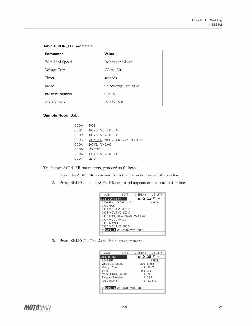
Sample Robot Job:
0000 NOP0001 MOVJ VJ=100.00002 MOVJ VJ=100.00003 AON_FR WFS=200 V=4 T=0.50004 MOVL V=1000005 ARCOF0006 MOVJ VJ=100.00007 END
To change AON_FR parameters, proceed as follows:1. Select the AON_FR command from the instruction side of the job line.
2. Press [SELECT]. The AON_FR command appears in the input buffer line.
3. Press [SELECT]. The Detail Edit screen appears.
Table 4 AON_FR Parameters
Parameter Value
Wire Feed Speed Inches per minute
Voltage Trim -30 to +30
Timer seconds
Mode 0= Synergic, 1= Pulse
Program Number 0 to 99
Arc Dynamic -5.0 to +5.0
JOB CONTENT J:WORK S:002 R1 0000 NOP 0001 MOVJ VJ=100.0 0002 MOVJ VJ=100.0 0003 AON_FR WFS=200 V=4 T=0.5 0004 MOVL V=100 0005 ARCOF 0006 MOVJ VJ=100.0
EDIT DISPLAYJOB UTILITYR1 SCL
TOOL:*
=>AON_FR WFS=200 V=4 T=0.5!
DETAIL EDIT AON_FR Wire Feed Speed 200 in/min Voltage Trim 4 -30:30 Timer 0.5 sec mode: Pls=1, Syn=0 0 0/1 Program Number 0 0:99 Arc Dynamic 0 -5.0:5.0
EDIT DISPLAYJOB UTILITYR1 SCL
TOOL:*
=>AON_FR WFS=200 V=4 T=0.5!
Final 21

System Manual Chapter 5 Operation
4. Cursor to the parameters you wish to change and press [SELECT].
5. Enter correct data using the number keypad and press [ENTER]. The new data is displayed in the Input Buffer line.
6. Press [ENTER] once more to register the data in the job or press [CANCEL] if you do not wish to register the data.
5.2.1.2 ASET_FR
The ASET_FR command is used to modify the weld parameters or operating mode during a weld. The output mode can be changed for Pulse or Synergic mode and Arc Dynamic, WFS, and Voltage Trim can be adjusted as well.
Sample Robot Job:
0000 NOP0001 MOVJ VJ=100.00002 MOVJ VJ=100.00003 AON_FR WFS=200 V=4 T=0.50004 MOVL V=1000005 ASET_FR WFS=180 V=-50006 MOVL V=1000007 ARCOF0008 MOVJ VJ=100.00009 END
To set ASET_FR parameters, proceed as follows:1. Select the ASET_FR command from the instruction side of the job line.
2. Press [SELECT]. The ASET_FR command appears in the input buffer line.
Table 5 ASET_FR Parameters
Parameter Value
Wire Feed Speed Inches per minute
Voltage Trim -30 to +30
Mode 0=Synergic, 1=Pulse
Arc Dynamic -5.0 to +5.0
JOB CONTENT J:WORK S:002 R1 0000 NOP 0001 MOVJ VJ=100.0 0002 MOVJ VJ=100.0 0003 AON_FR WFS=200 V=4 T=0.5 0004 MOVL V=100 0005 ASET_FR WFS=180 V=-5 0006 MOVL V=100
EDIT DISPLAYJOB UTILITYR1 SCL
TOOL:*
=>ASET_FR WFS=180 V=-5!
22 Final
Robotic Arc Welding148881-2
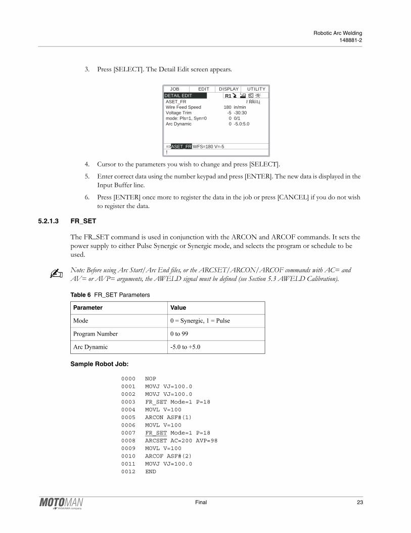
3. Press [SELECT]. The Detail Edit screen appears.
4. Cursor to the parameters you wish to change and press [SELECT].
5. Enter correct data using the number keypad and press [ENTER]. The new data is displayed in the Input Buffer line.
6. Press [ENTER] once more to register the data in the job or press [CANCEL] if you do not wish to register the data.
5.2.1.3 FR_SET
The FR_SET command is used in conjunction with the ARCON and ARCOF commands. It sets the power supply to either Pulse Synergic or Synergic mode, and selects the program or schedule to be used.
Note: Before using Arc Start/Arc End files, or the ARCSET/ARCON/ARCOF commands with AC= and AV= or AVP= arguments, the AWELD signal must be defined (see Section 5.3 AWELD Calibration).
Sample Robot Job:
0000 NOP0001 MOVJ VJ=100.00002 MOVJ VJ=100.00003 FR_SET Mode=1 P=180004 MOVL V=1000005 ARCON ASF#(1)0006 MOVL V=1000007 FR_SET Mode=1 P=180008 ARCSET AC=200 AVP=980009 MOVL V=1000010 ARCOF ASF#(2)0011 MOVJ VJ=100.00012 END
DETAIL EDIT ASET_FR Wire Feed Speed 180 in/min Voltage Trim -5 -30:30 mode: Pls=1, Syn=0 0 0/1 Arc Dynamic 0 -5.0:5.0
EDIT DISPLAYJOB UTILITYR1 SCL
TOOL:*
=>ASET_FR WFS=180 V=-5!
Table 6 FR_SET Parameters
Parameter Value
Mode 0 = Synergic, 1 = Pulse
Program Number 0 to 99
Arc Dynamic -5.0 to +5.0
Final 23

System Manual Chapter 5 Operation
To set FR_SET parameters, proceed as follows:1. Select the FR_SET command from the instruction side of the job line.
2. Press [SELECT]. The FR_SET command appears in the input buffer line.
3. Press [SELECT]. The Detail Edit screen appears.
4. Cursor to the parameters you wish to change and press [SELECT].
5. Enter correct data using the number keypad and press [ENTER]. The new data is displayed in the Input Buffer line.
6. Press [ENTER] once more to register the data in the job or press [CANCEL] if you do not wish to register the data.
5.3 Robot Controller-Power Supply Calibration
Although the AWELD signal always directly controls the wire feeding speed, the robot programming pendant can be calibrated to display one of two values for the AWELD signal: Wire Feed Speed (recommended) or Amperage. Power trim calibration is especially useful when operating with multiple wire types and/or wire diameters.
Before welding using Arc Start/Arc End files, or the ARCSET/ARCON/ARCOF commands with AC= and AV= or AVP= arguments, the AWELD/VWELD signals must be defined to determine what value will be displayed on the programming pendant. The AWELD signal value is determined by a table in the Welder Condition File.
Note: Regardless of calibration (wire feed speed, amperage, or power trim), it is not possible to modify the Arc Start and Arc End Files to display “in./min.” on the programming pendant” The display will always show “(A).”
JOB CONTENT J:WORK S:002 R1 0000 NOP 0001 MOVJ VJ=100.0 0002 MOVJ VJ=100.0 0003 FR-SET Mode=1 P=18 0004 MOVL V=100 0005 ARCON ASF# (1) 0006 MOVL V=100
EDIT DISPLAYJOB UTILITYR1 SCL
TOOL:*
=>FR_SET Mode=1 P=18!
DETAIL EDIT FR_SET mode: Pls=1, Syn=0 0 0/1 Program Number 6 0:99 Arc Dynamic 0 -5.0:5.0
EDIT DISPLAYJOB UTILITYR1 SCL
TOOL:*
=>FR_SET Mode=0 P=6!
24 Final

Robotic Arc Welding148881-2
Note: The AON_FR and ASET_FR robot job commands do not require the following calibration procedures.
5.3.1 AWELD = Wire Feed Speed
To calibrate the AWELD signal to wire feed speed, proceed as follows:1. Open Welder Condition File (TOP MENU > ARCWELDING > WELDER CONDITION).
2. Verify POWER SUPPLY is set to A/%, not A/V (used for Standard mode only).
3. Scroll down to Welding Current Output Characteristics.
4. Modify Welding Current Output Characteristics using appropriate values from the following table.
WELDER CONDITION WELDER NO. SETTING :DONE WELDER NAME :FRONIUS COMM.:AWELD=WFS POWER SUPPLY :A/% SHIELDING GAS :CO2 WIRE DIA. : 1.2 mm WIRE EXT. : 15 mm WIRE ANTI-STICKING : 0.3 sec ARC SHORTAGE STOP :1.50 sec
EDIT DISPLAYDATA UTILITYR1 SCL
!
:1
WELDER CONDITION <WELDING CURRENT OUTPUT CHAR.> RANGE:+ ADJUST :1.00 NO. REF.(V) MEASURE(A) 01 0.00 60 02 5.00 460 03 10.00 860 04 0.00 0 05 0.00 0 06 0.00 0 07 0.00 0
EDIT DISPLAYDATA UTILITYR1 SCL
!
Table 7 Wire Feed Speed (WFS) Calibration for TS5000 and TPS5000
Ref. (V)0.9 SteelMeasured (A)
1.2 SteelMeasured (A)
1.6 SteelMeasured (A)
0.9 4043 AlMeasured (A)
1.2 4043 AlMeasured (A)
1.6 4043 AlMeasured (A)
0.00 60 60 45 195 195 100
5.00 460 460 200 530 420 245
10.00 860 860 350 860 640 390
Final 25

System Manual Chapter 5 Operation
5. Scroll down to Welding Voltage Output Characteristics.
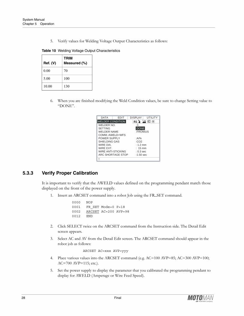
6. Verify values for Welding Voltage Output Characteristics as follows:
7. When you are finished modifying the Weld Condition values, be sure to change Setting value to “DONE”.
Table 8 Welding Voltage Output Characteristics
Ref. (V)TRIM Measured (%)
0.00 70
5.00 100
10.00 130
WELDER CONDITION <WELDING VOLTAGE OUTPUT CHAR.> RANGE:+ ADJUST :1.00 NO. REF.(V) MEASURE(%) 01 0.00 70 02 5.00 100 03 10.00 130 04 0.00 0 05 0.00 0 06 0.00 0 07 0.00 0
EDIT DISPLAYDATA UTILITYR1 SCL
!
WELDER CONDITION WELDER NO. SETTING :DONE WELDER NAME :FRONIUS COMM.:AWELD=WFS POWER SUPPLY :A/% SHIELDING GAS :CO2 WIRE DIA. : 1.2 mm WIRE EXT. : 15 mm WIRE ANTI-STICKING : 0.3 sec ARC SHORTAGE STOP :1.50 sec
EDIT DISPLAYDATA UTILITYR1 SCL
!
:1
26 Final
Robotic Arc Welding148881-2
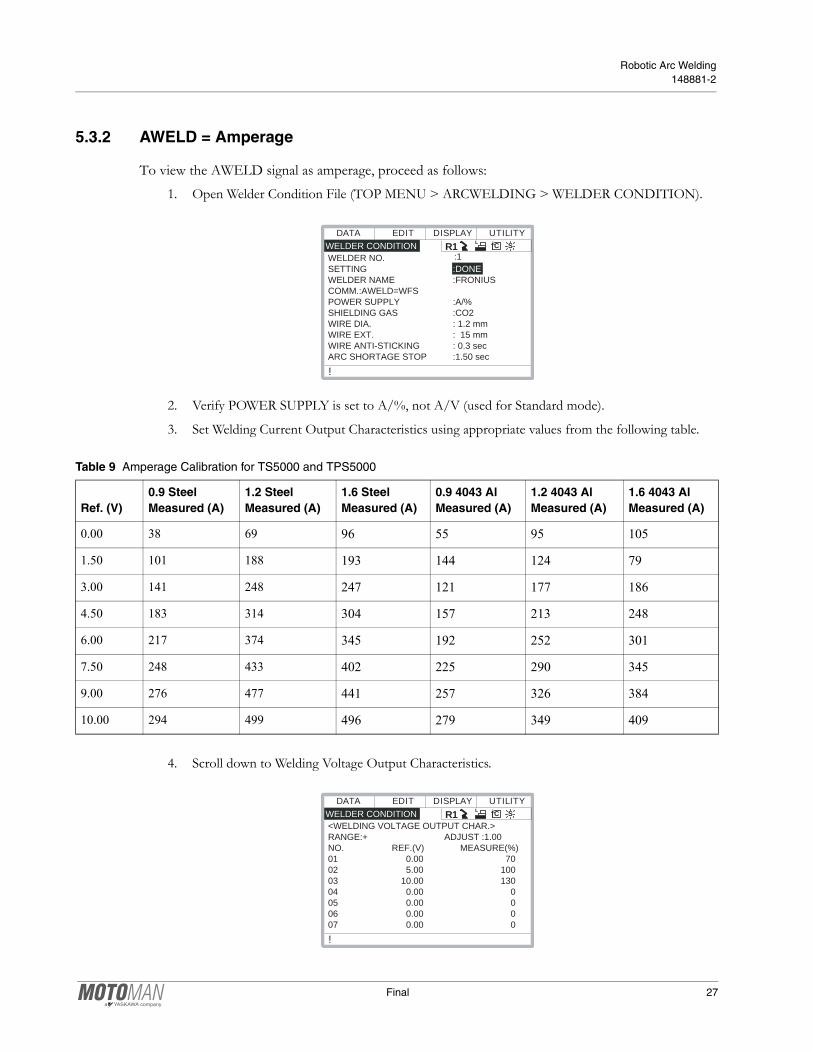
5.3.2 AWELD = Amperage
To view the AWELD signal as amperage, proceed as follows:1. Open Welder Condition File (TOP MENU > ARCWELDING > WELDER CONDITION).
2. Verify POWER SUPPLY is set to A/%, not A/V (used for Standard mode).
3. Set Welding Current Output Characteristics using appropriate values from the following table.
4. Scroll down to Welding Voltage Output Characteristics.
WELDER CONDITION WELDER NO. SETTING :DONE WELDER NAME :FRONIUS COMM.:AWELD=WFS POWER SUPPLY :A/% SHIELDING GAS :CO2 WIRE DIA. : 1.2 mm WIRE EXT. : 15 mm WIRE ANTI-STICKING : 0.3 sec ARC SHORTAGE STOP :1.50 sec
EDIT DISPLAYDATA UTILITYR1 SCL
!
:1
Table 9 Amperage Calibration for TS5000 and TPS5000
Ref. (V)0.9 SteelMeasured (A)
1.2 SteelMeasured (A)
1.6 SteelMeasured (A)
0.9 4043 AlMeasured (A)
1.2 4043 AlMeasured (A)
1.6 4043 AlMeasured (A)
0.00 38 69 96 55 95 105
1.50 101 188 193 144 124 79
3.00 141 248 247 121 177 186
4.50 183 314 304 157 213 248
6.00 217 374 345 192 252 301
7.50 248 433 402 225 290 345
9.00 276 477 441 257 326 384
10.00 294 499 496 279 349 409
WELDER CONDITION <WELDING VOLTAGE OUTPUT CHAR.> RANGE:+ ADJUST :1.00 NO. REF.(V) MEASURE(%) 01 0.00 70 02 5.00 100 03 10.00 130 04 0.00 0 05 0.00 0 06 0.00 0 07 0.00 0
EDIT DISPLAYDATA UTILITYR1 SCL
!
Final 27
System Manual Chapter 5 Operation
5. Verify values for Welding Voltage Output Characteristics as follows:
6. When you are finished modifying the Weld Condition values, be sure to change Setting value to “DONE”.
5.3.3 Verify Proper Calibration
It is important to verify that the AWELD values defined on the programming pendant match those displayed on the front of the power supply.
1. Insert an ARCSET command into a robot Job using the FR_SET command.
0000 NOP0001 FR_SET Mode=0 P=180002 ARCSET AC=200 AVP=980012 END
2. Click SELECT twice on the ARCSET command from the Instruction side. The Detail Edit screen appears.
3. Select AC and AV from the Detail Edit screen. The ARCSET command should appear in the robot job as follows:
ARCSET AC=xxx AVP=yyy
4. Place various values into the ARCSET command (e.g. AC=100 AVP=85; AC=300 AVP=100; AC=700 AVP=115; etc.).
5. Set the power supply to display the parameter that you calibrated the programming pendant to display for AWELD (Amperage or Wire Feed Speed).
Table 10 Welding Voltage Output Characteristics
Ref. (V)TRIM Measured (%)
0.00 70
5.00 100
10.00 130
WELDER CONDITION WELDER NO. SETTING :DONE WELDER NAME :FRONIUS COMM.:AWELD=WFS POWER SUPPLY :A/% SHIELDING GAS :CO2 WIRE DIA. : 1.2 mm WIRE EXT. : 15 mm WIRE ANTI-STICKING : 0.3 sec ARC SHORTAGE STOP :1.50 sec
EDIT DISPLAYDATA UTILITYR1 SCL
!
:1
28 Final

Robotic Arc Welding148881-2
Note: Power Trim value cannot be displayed on the power supply
During day-to-day operation, the alpha-numeric displays of the power supply provides the following functions:
6. Execute the ARCSET command by holding down the INT LOCK key and pressing FWD. Each time a value is executed, look at the display on the power supply and verify the requested job value matches the value displayed on the power supply.
Table 11 Power Supply Displays
State Left Display Right Display
Not Welding Wire Feed Speed Arc Length Correction/Trim
Anticipated Amperage Arc Dynamic
Recommended Thickness Anticipated Welding Voltage
Job Number
Welding Actual Amperage Actual Welding Voltage
1 Second After Welding Actual Amperage Actual Welding Voltage
Table 12 AWELD = Amperage (Synergic modes)
AC (Job Value)Amps (Fronius Display) AVP (Job Value)
Trim (Fronius Display)
120A 120A 70% -30%
200A 200A 100% 0
280A 280A 130% 30%
JOBN°
AMPERAGE WIRE FEED SPEED
TRIM (AVP VALUE)
WELDING VOLTAGE
Final 29

System Manual Chapter 5 Operation
Job Value is the value set in the ARCSET command of the robot job. Fronius Display is thevalue displayed on the power supply.
5.4 Job Mode
An alternate way to control the power supply is to use jobs stored in the power supply. Several welding parameters including; wire feed speed (termed “Power” by the power supply), and voltage trim are saved in jobs contained in the power supply memory. These jobs can be modified, copied, or deleted locally using the front panel of the power supply, or by remote PC software. There are typically 100 jobs available. These jobs are selected the same way (same I/O bits) as Program selections were made above. Each individual job can be set up for Synergic or Pulse Synergic operation, and contain parameters to adjust starting and ending parameters, gas flow timing, arc dynamic, and others. Each job is also set up for a material type, wire diameter, and gas type.
There are also job parameters that allow the user to control primary welding variables to a limited degree from the robot controller.AL.c (Arc Length Correction) Allows VWELD to adjust voltage trim from the value stored in the
Fronius job. Maximum correction boundary window is -30% to +30%
PcL (Power Control Low) Allows the AWELD channel to decrease the WFS by up to 20% of the value stored in the Fronius job.
PcH (Power Control High) Allows the AWELD channel to increase the WFS by up to 20% of the value stored in the Fronius job.
Table 13 AWELD = Wire Feed Speed (Synergic modes)
AC (Job Value)WFS (Fronius Display) AV (Job Value)
Trim (Fronius Display)
120A 120 in/min. 70% -30%
200A 200 in/min. 100% 0
280A 280 in/min. 130% 30%
Table 14 AWELD = Power Trim (Synergic modes)
AC (Job Value)Power Trim (Fronius Display) AV (Job Value)
Trim (Fronius Display)
120A 12% of max WFS 70% -30%
500A 50% of max WFS 100% 0
920A 92% of max WFS 130% 30%
30 Final
Robotic Arc Welding148881-2
5.4.1 Robot Job Commands for Job Mode
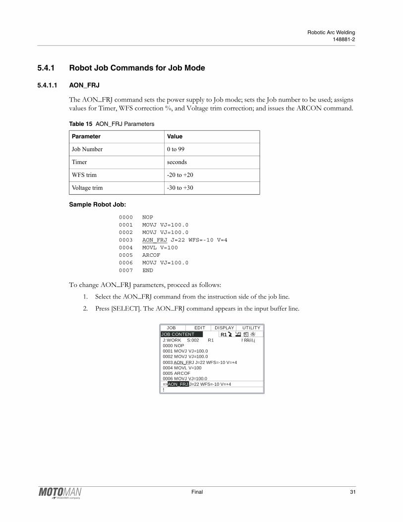
5.4.1.1 AON_FRJ
The AON_FRJ command sets the power supply to Job mode; sets the Job number to be used; assigns values for Timer, WFS correction %, and Voltage trim correction; and issues the ARCON command.
Sample Robot Job:
0000 NOP0001 MOVJ VJ=100.00002 MOVJ VJ=100.00003 AON_FRJ J=22 WFS=-10 V=40004 MOVL V=1000005 ARCOF0006 MOVJ VJ=100.00007 END
To change AON_FRJ parameters, proceed as follows:1. Select the AON_FRJ command from the instruction side of the job line.
2. Press [SELECT]. The AON_FRJ command appears in the input buffer line.
Table 15 AON_FRJ Parameters
Parameter Value
Job Number 0 to 99
Timer seconds
WFS trim -20 to +20
Voltage trim -30 to +30
JOB CONTENT J:WORK S:002 R1 0000 NOP 0001 MOVJ VJ=100.0 0002 MOVJ VJ=100.0 0003 AON_FRJ J=22 WFS=-10 V=+4 0004 MOVL V=100 0005 ARCOF 0006 MOVJ VJ=100.0
EDIT DISPLAYJOB UTILITYR1 SCL
TOOL:*
=>AON_FRJ J=22 WFS=-10 V=+4!
Final 31

System Manual Chapter 5 Operation
3. Press [SELECT]. The Detail Edit screen appears.
4. Cursor to the parameters you wish to change and press [SELECT].
5. Enter correct data using the number keypad and press [ENTER]. The new data is displayed in the Input Buffer line.
6. Press [ENTER] once more to register the data in the job or press [CANCEL] if you do not wish to register the data.
Table 16
Reference Voltage Voltage Trim Wire Feed Speed (WFS)
0.0V -AL.c value WFS set value - PcL value
5.0V V Trim value set in Job WFS value set in Job
10.0V +AL.c value WFS set value +PcH value
DETAIL EDIT AON_FRJ Job Number 22 Timer 6 sec WFS Trim -10 -20:+20 Voltage Trim 4 -30:+30
EDIT DISPLAYJOB UTILITYR1 SCL
TOOL:*
=>AON_FRJ J=22 WFS=-10 V=4!
32 Final

Robotic Arc Welding148881-2
Index
AANSI/RIA, 5AON_FR, 20AON_FRJ, 31ASET_FR, 22AWELD = Amperage, 27AWELD = Wire Feed Speed, 25
CComponents, 3Customer Service, 4
DDocumentation, 3
EEquipment Description, 11
FFR_SET, 23Fronius Power Supplies, 11
GGas Metal Arc Welding, 15General Safeguarding Tips, 6Globular Transfer, 16
IInstallation Safety, 7Introduction, 1
JJob Mode, 12, 30
LLocal Control, 20
MMaintenance Safety, 8Mechanical Safety Devices, 7
OOperation, 19
Safety, 8
PProgram (Schedule Select) Control, 20Programming
Operation, and Maintenance Safety, 8Safety, 8
Pulsed Gas Metal Arc Welding, 17
RResistance Measurement, 12ROB 5000 Interface, 14Robacta Torch, 12Robot
Controller, 11Controller-Power Supply Calibration, 24Job Commands
Job Mode, 31Program Mode, 20
Robotic Industries Association, 5
SSafeguarding Tips, 6Safety, 5
Devices, 7Short-Circuit Transfer, 16Software, 12Spray Transfer, 17Synergic Control, 13System Configuration, 2
TTheory of Operation, 15
Final 33

System Manual Index
VVerify Proper Calibration, 28VR1500 Wire Feeder, 13
WWater Circulator, 14Welding Circuit Resistance Measurement, 12Wire Feeder, 13
34 Final