motorola, the stylized m logo, and all other trademarks ... · pdf filecomputer software...
TRANSCRIPT


Motorola, the Stylized M Logo, and all other trademarks indicated as such herein are Trademarks of Motorola, Inc. Reg. U.S. Pat. & Tm. Off. © 2007 Motorola, Inc. All rights reserved. Printed in the U.S.A.

1 English
CO
NTEN
TS
harging Options . .12tery . . . . . . . . . . . .12d Disposal . . . . . .13-Ion (Li-Ion) Battery .. . . . . . . . . . . . . . .14m-Ion (Li-Ion) Battery. . . . . . . . . . . . . . . . .14k (optional accessory). . . . . . . . . . . . . . . .15ttery . . . . . . . . . .15atteries. . . . . . . . .15tors and Drop-in Tray . . . . . . . . . . . . . . .16ion Belt Clip. . . . . .17ion . . . . . . . . . . . .17. . . . . . . . . . . . . . .19op-in Tray Single Unit . . . . . . . . . . . . . . .19one Battery. . . . . .20 Battery . . . . . . . .20In Charger’s Position tery . . . . . . . . . . . .21
CONTENTSContents . . . . . . . . . . . . . . . . . . . . . . . . . . 1Computer Software Copyrights . . . . . . . 4Safety . . . . . . . . . . . . . . . . . . . . . . . . . . . . 5Product Safety and RF Exposure Compliance . . . . . . . . . . . . . . . . 5Batteries and Chargers Safety Information. . . . . . . . . . . . . . . . . . . . . . . . . . . . . . . . . . .6Operational Safety Guidelines . . . . . . . . . . 7Radio Overview . . . . . . . . . . . . . . . . . . . . 8Parts of the radio . . . . . . . . . . . . . . . . . . . . 8
ON/OFF/Volume Knob . . . . . . . . . . . . . 9Microphone . . . . . . . . . . . . . . . . . . . . . . 9Antenna. . . . . . . . . . . . . . . . . . . . . . . . . 9Accessory Connector . . . . . . . . . . . . . . 9Model Label. . . . . . . . . . . . . . . . . . . . . . 9LED Indicator . . . . . . . . . . . . . . . . . . . . 9Side Buttons . . . . . . . . . . . . . . . . . . . . 10The Lithium-Ion (Li-Ion) Battery . . . . . 10
Batteries and Chargers . . . . . . . . . . . . . 12
Battery Features and CAbout the Li-Ion BatBattery Recycling anInstalling the Lithium. . . . . . . . . . . . . . . Removing the Lithiu. . . . . . . . . . . . . . . .Alkaline Battery Pac. . . . . . . . . . . . . . . .Installing Alkaline BaRemoving Alkaline BPower Supply, AdapCharger. . . . . . . . . .Installing Spring ActBattery Life InformatCharging the BatteryCharging with the DrCharger. . . . . . . . . .Charging a Stand-AlCharging a StandardIdentifying the Drop-Before Charging Bat

En
CO
NTE
NTS
faults . . . . . . . . . .32 Tone (Roger Beep . . . . . . . . . . . . . . .33 . . . . . . . . . . . . . . .33 . . . . . . . . . . . . . . .33sensitivity . . . . . . .34s . . . . . . . . . . . . . .38Mode. . . . . . . . . . .38ption) Frequencies. .
. . . . . . . . . . . . . . .39ption) Codes (CTCSS/
. . . . . . . . . . . . . . .39ption) Bandwidth .40 L . . . . . . . . . . . . .41 Number of Channels.
. . . . . . . . . . . . . . .41s. . . . . . . . . . . . . .42ne Gain Level . . . .43ne Accessory Gain . . . . . . . . . . . . . . .44. . . . . . . . . . . . . . .44
2glish
Charging a High Capacity Battery. . . . 22Drop-in Tray Charger LED Indicators . 23Estimated Charging Time . . . . . . . . . . 24Charging a Radio and Battery Using a Multi-Unit Charger-MUC (Optional Accessory) . . . . . . . . . . . . . . . . . . . . . . . . . . . . . . . 24
Getting Started . . . . . . . . . . . . . . . . . . . . 26Turning radio ON/OFF . . . . . . . . . . . . . . . 26Adjusting volume . . . . . . . . . . . . . . . . . . . 26Reading the Display . . . . . . . . . . . . . . . . . 26Selecting a Channel . . . . . . . . . . . . . . . . . 27Talking and Monitoring. . . . . . . . . . . . . . . 27Receiving a Call . . . . . . . . . . . . . . . . . . . . 27
Signal Strength Indicator and Channel Busy Indicators. . . . . . . . . . . . . . . . . . . . . . . 28
Talk Range. . . . . . . . . . . . . . . . . . . . . . . . 28Hands-Free Use/VOX . . . . . . . . . . . . . . . 31
With Compatible VOX Accessories. . . 31Hands Free without Accessories (iVOX). . . . . . . . . . . . . . . . . . . . . . . . . . . . . . . . 32Battery Save . . . . . . . . . . . . . . . . . . . . 32
Reset To Factory DeEnd of TransmissionTone) . . . . . . . . . . .Keypad Beeps . . . .MENU Options . . . .Setting VOX / iVOX
Programming FeatureEntering Programming Programming RX (Rece. . . . . . . . . . . . . . . . . . .Programming RX (ReceDPL) . . . . . . . . . . . . . .Programming RX (ReceProgramming ScrambleProgramming Maximum. . . . . . . . . . . . . . . . . . .Programming Call ToneProgramming MicrophoProgramming MicrophoLevel . . . . . . . . . . . . . .Programming Scan List

3 English
CO
NTEN
TS
. . . . . . . . . . . . . . .64 . . . . . . . . . . . . . . .64 . . . . . . . . . . . . . . .64 . . . . . . . . . . . . . . .65
Programming Buttons . . . . . . . . . . . . . . . 45Editing Channel Alias Name . . . . . . . . . . 46Nuisance Channel Delete . . . . . . . . . . . . 47CPS (Computer Programming Software). 48
Bandwidth Select . . . . . . . . . . . . . . . . 48Time-Out Timer . . . . . . . . . . . . . . . . . . 48Battery Type Setting . . . . . . . . . . . . . . 49Call Tones . . . . . . . . . . . . . . . . . . . . . . 49Scramble. . . . . . . . . . . . . . . . . . . . . . . 49
Cloning Radios. . . . . . . . . . . . . . . . . . . . . 50What to do if cloning fails . . . . . . . . . . 52
Troubleshooting. . . . . . . . . . . . . . . . . . . 54Use and Care . . . . . . . . . . . . . . . . . . . . . 57Frequency and Code Charts . . . . . . . . . 58Motorola Limited Warranty . . . . . . . . . . 62Warranty information . . . . . . . . . . . . . . . . 62What Is Not Covered By The Warranty . . 62Accessories . . . . . . . . . . . . . . . . . . . . . . 64Audio Accessories . . . . . . . . . . . . . . . . . . 64Battery . . . . . . . . . . . . . . . . . . . . . . . . . . . 64
Carry Accessories . . . .Software Applications .Cables . . . . . . . . . . . . .Chargers . . . . . . . . . . .

CO
MPU
TER
SO
FTW
AR
E C
OPY
RIG
HTS
4English
The Motorola products described in this manual may include copyrighted Motorola computer programs stored in semiconductor memories or other media. Laws in the United States and other countries preserve for Motorola certain exclusive rights for copyrighted computer programs, including, but not limited to, the exclusive right to copy or reproduce in any form the copyrighted computer program. Accordingly, any copyrighted Motorola computer programs contained in the Motorola products described in this manual may not be copied, reproduced, modified, reverse-engineered, or distributed in any manner without the express written permission of Motorola.
Furthermore, the purchase of Motorola products shall not be deemed to grant either directly or by implication, estoppel, or otherwise, any license under the copyrights, patents or patent applications of Motorola, except for the normal non-exclusive license to use that arises by operation of law in the sale of a product.
COMPUTER SOFTWARE COPYRIGHTS

5 English
SAFETY
SAFETY
PRODUCT SAFETY AND RF EXPOSURE COMPLIANCE
ATTENTION!This radio is restricted to occupational use only to satisfy FCC RF energy exposure requirements.
For a list of Motorola-approved antennas, batteries, and other accessories, visit the following website which lists approved accessories:
http://www.motorola.com/XTNiBefore using this product, read the operating instructions and RF energy awareness information contained in the Product Safety and RF Exposure booklet enclosed with your radio.
!C a u t i o n

BA
TTER
IES
AN
D C
HA
RG
ERS
SAFE
TY IN
FOR
MA
TIO
N
E
ould not be used unless . Use of an improper result in risk of fire and xtension cord must be the cord size is 18AWG eet (2.0 m), and 16AWG eet (3.0 m).
electric shock, or injury, arger if it has been broken ay. Take it to a qualified esentative.
he charger; it is not ement parts are not ly of the charger may cal shock or fire.
tric shock, unplug the outlet before attempting leaning
6nglish
BATTERIES AND CHARGERS SAFETY INFORMATION
This document contains important safety and operating instructions. Read these instructions carefully and save them for future reference. Before using the battery charger, read all the instructions and cautionary markings on
• the charger,
• the battery, and
• the radio using the battery.
1. To reduce risk of injury, charge only the rechargeable Motorola-authorised batteries. Other batteries may explode, causing personal injury and damage.
2. Use of accessories not recommended by Motorola may result in risk of fire, electric shock, or injury.
3. To reduce risk of damage to the electric plug and cord, pull by the plug rather than the cord when disconnecting the charger.
4. An extension cord shabsolutely necessaryextension cord could electric shock. If an eused, make sure thatfor lengths up to 6.5 ffor lengths up to 9.8 f
5. To reduce risk of fire,do not operate the chor damaged in any wMotorola service repr
6. Do not disassemble trepairable and replacavailable. Disassembresult in risk of electri
7. To reduce risk of eleccharger from the AC any maintenance or c

BA
TTERIES A
ND
CH
AR
GER
S SA
FETY INFO
RM
ATIO
N
7 English
perature around the nt must not exceed 40°C
ocated where it will not be er, or subjected to water,
OPERATIONAL SAFETY GUIDELINES
• Turn the radio OFF when charging battery.
• The charger is not suitable for outdoor use. Use only in dry locations/conditions.
• Connect charger only to an appropriately fused and wired supply of the correct voltage (as specified on the product).
• Disconnect charger from line voltage by removing main plug.
• The outlet to which this equipment is connected should be nearby and easily accessible.
• Maximum ambient tempower supply equipme(104°F).
• Make sure the cord is lstepped on, tripped ovdamage, or stress.

8English
RA
DIO
OVE
RVI
EW
RADIO OVERVIEW
Antenna
Microphone ON/OFF/Volume
Accessory Connector
Model Label
PTT (Push-to-Talk) Button
SB1 - Monitor Button
SB2 - Scan/Nuisance Channel Delete
Lithium-Ion Battery
Use ‘Menu’ button to lock keypad
Use / to scroll up/down through channels and menu setting
Front Buttons
LED Indicator
LED Indicator
PARTS OF THE RADIO

9 English
RA
DIO
OVER
VIEW
cess to set up features attery type, etc. It also ugh all the features ode
/ down buttons
own the menu options values. These buttons uttons.
ON/OFF/Volume Knob
Used to turn the radio ON or OFF and to adjust the radio’s volume.
Microphone
Speak clearly into the microphone when sending a message.
Antenna
The radio’s antenna is non-removable.
Accessory Connector
Used to connect compatible audioaccessories.
Model Label
Indicate the model of the radio
LED Indicator
Used to give battery status, power-up status, radio call information and scan status.
Front Buttons
• Button
This button gives you aclike VOX/iVOX levels, ballows you to move throwhile in Programming M
• / Toggle up
Allows you to scroll up/dor set up programming are not programmable b
M E N U
RA
DIO
OVE
RVI
EW
ming Software)” on
utton
is button to talk,
eneral button that can S. The default setting nitor".
eneral button that can S. The SB2 button
Nuisance Channel
) Battery
different types of rmation, see “Battery Options” on page 12.
10English
• Programmable Button
Default set to generate the current programmed call tone.
• Programmable Button
Default set to preset channel 1
• Programmable Button
Default set to preset channel 2
Note: A short press of either preset button (B or C) tunes the radio to the preset channel and the radio will play a good chirp. You can assign different functions to these buttons via the CPS. For example: Backlight Time Out, Reverse Burst, Power Select, Scan/Nuisance Channel Delete, Monitor and Call Tones. To learn more about how to program these buttons refer to “Entering Programming Mode” on page 38 and “CPS
(Computer Programpage 48.
Side Buttons
• Push-to-Talk (PTT) B
Press and hold down threlease it to listen.
• Side Button 1 (SB1)
The Side Button 1 is a gbe configured by the CPof the SB1 button is "Mo
• Side Button 2 (SB2)
The Side Button 2 is a gbe configured by the CPdefault setting is ‘Scan/Delete’.
The Lithium-Ion (Li-Ion
XTNi™ Series providesbatteries. For more infoFeatures and Charging
A
B
C

11 English
RA
DIO
OVER
VIEW
This User Guide covers multiple radio models, and may detail some features your radio does not have. The model number of the radio is shown on the front of the radio, underneath the
speaker, and tells you the following information:
Model Frequency Band
Transmit Power (Watts)
Number of Channels Antenna
XTNiD PMR446 0.5 8 Non-removable

BA
TTER
IES
AN
D cycles than a battery
overcharge and is day. Further, a battery overcharging and harge, lasts even
esigned specifically to charger and vice Motorola equipment age and void the ttery should be at temperature),
rging a cold battery y result in leakage of
ly in failure of the battery (above 95°F d discharge capacity,
ce of the radio. ery chargers contain a cuit to ensure that ithin the temperature
12English
CH
AR
GER
S
BATTERIES AND CHARGERSXTNi™ Series radios provide Lithium-Ion (Li-Ion) batteries that comes in different capacities that will define the battery life. It also offers the option to use Alkaline batteries.The radio comes equipped with a rapid charger.
BATTERY FEATURES AND CHARGING OPTIONS
About the Li-Ion Battery
The XTNi™ radio series come equipped with a rechargeable Li-Ion battery. This battery should be charged before initial use to ensure optimum capacity and performance. Battery life is determined by several factors. Among the more critical are the regular overcharge of batteries and the average depth of discharge with each cycle. Typically, the greater the overcharge and the deeper the average discharge, the fewer cycles a battery will last. For example, a battery which is overcharged and discharged 100% several
times a day, lasts fewerthat receives less of andischarged to 50% per which receives minimalaverages only 25% disclonger.Motorola batteries are dbe used with a Motorolaversa. Charging in non-may lead to battery dambattery warranty. The baabout 77°F (25°C) (roomwhenever possible. Cha(below 50° F [10°C]) maelectrolyte and ultimatebattery. Charging a hot [35°C]) results in reduceaffecting the performanMotorola rapid-rate batttemperature-sensing cirbatteries are charged wlimits stated above.

13 English
BA
TTERIES A
ND
C
HA
RG
ERS
ers participate in this n of the drop-off facility BRC's Internet web
call 1-800-8- site and telephone ther useful information tions for consumers, mental agencies.
Battery Recycling and Disposal
Li-Ion rechargeable batteries can be recycled. However, recycling facilities may not be available in all areas. Under various U.S. state laws and the laws of several other countries, batteries must be recycled and cannot be disposed of in landfills or incinerators. Contact your local waste management agency for specific requirements and information in your area. Motorola fully endorses and encourages the recycling of Li-Ion batteries. In the U.S. and Canada, Motorola participates in the nationwide Rechargeable Battery Recycling Corporation (RBRC) program for Li-Ion battery collection and recycling.
Many retailers and dealprogram. For the locatioclosest to you, access Rsite at www.rbrc.com orBATTERY. This internetnumber also provides oconcerning recycling opbusinesses and govern
BA
TTER
IES
AN
D -Ion (Li-Ion) Battery
y latch and hold it oving the battery.
from the radio.
battery latch
14English
CH
AR
GER
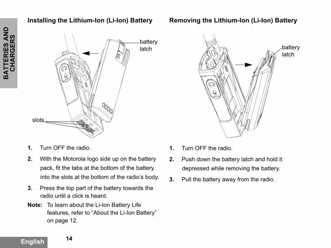
SInstalling the Lithium-Ion (Li-Ion) Battery
1. Turn OFF the radio.
2. With the Motorola logo side up on the battery pack, fit the tabs at the bottom of the battery into the slots at the bottom of the radio’s body.
3. Press the top part of the battery towards the radio until a click is heard.
Note: To learn about the Li-Ion Battery Life features, refer to “About the Li-Ion Battery” on page 12.
Removing the Lithium
1. Turn OFF the radio.
2. Push down the batterdepressed while rem
3. Pull the battery away
battery latch
slots

15 English
BA
TTERIES A
ND
C
HA
RG
ERS
tteries
it is turned ON.
es, on both sides of the
tery away from the radio’s ery from the radio’s body.
Alkaline Battery Pack (optional accessory)Installing Alkaline Battery
1. Turn OFF the radio, if it is turned ON.
2. Remove Li-Ion battery
3. Assemble alkaline battery pack (optional accessory) in the same steps as installing the Li-Ion battery pack.
4. Remove battery door from alkaline battery pack.
5. Slide the 5 AA alkaline batteries into the frame, matching the markings inside the compartment.
Removing Alkaline Ba
1. Turn OFF the radio, if
2. Slide the battery latchbattery, downwards.
3. Pull the top of the batbody, and lift the batt

BA
TTER
IES
AN
D
r grooves into the power o place.
rd to remove.
in the pictures are just oses. The adaptor you be different.
Remove
Adaptor
Power Supply
16English
CH
AR
GER
SPower Supply, Adaptors and Drop-in Tray Charger
Your radio comes with one Drop-in Tray Charger, one Power Supply (also known as "transformer") and a set of adaptors.Your power supply, has a "switchable" capability which allows to suit any of the adaptors that comes with your radio package. The adaptor you should choose to install depends on the region you're located.Once you have identified the adaptor that matches your electrical outlet, proceed to install it as follows:
• Slide down the adaptosupply until it snaps int
• Slide the adaptor upwa
Note: The adaptor shownfor illustration purpshould install may
Drop-in Tray Charger
Power Supply
Install
Power Supply
Adaptor

17 English
BA
TTERIES A
ND
C
HA
RG
ERS
the metal release tab on ush the spring action belt e.
n
model and/or region be different. This e estimated battery ave feature is ON battery life will be
When acquiring additional chargers or power supplies, make sure you have similar drop-in tray chargers and power supplies set. For part number details refer to “Chargers” on page 65.
Installing Spring Action Belt Clip
1. Slide the spring action belt clip rails into the belt clip grooves on the back of the battery pack and slide it down until the belt clip tab snaps into place.
2. To remove, pull back the belt clip tab and pclip upward to remov
Battery Life Informatio
Li-Ion Battery Life
Depending on the radiothe battery capacity willfeature will determine thlife. When the Battery S(enabled by default) thelonger.
belt clip tab
Spring Action Belt Clip

BA
TTER
IES
AN
D
ides estimations about e Alkaline Batteries:
attery Life
ature 0.5 Watt
35 hours
eing estimated nsmit/ 5% receive/ ndard duty cycle.
18English
CH
AR
GER
SThe following chart summarizes battery life estimations:
Li-Ion Battery Life
Alkaline Battery Life
The following chart provthe Battery Life using th
Li-Ion Battery Life with Battery Save feature ON
Battery 0.5 Watt
Standard 16 hours
High Capacity 32 hours
Note: Battery life is estimated based on 5% transmit/ 5% receive/ 90% standby standard duty cycle.
Alkaline B
Battery Save Fe
ON
Note:
• Battery life are bbased on 5% tra90% standby sta

19 English
BA
TTERIES A
ND
C
HA
RG
ERS
p-in Tray Single Unit
charger on a flat surface.
f the power supply into f the drop-in tray charger.
into a power outlet.
e tray with the front of the of the charger, as shown. attery attached to a radio, to ensure a full charge. afety Guidelines” on
formation.
Power Supply(Transformer)
Battery Meter
The battery meter located in the upper left corner of the display indicates how much battery power you have remaining.
Charging the Battery
To charge the battery (with the radio attached), place it in a Motorola-approved Drop-in Tray Single Unit Charger or Drop-in Tray Multi-Unit Charger.
Charging with the DroCharger
1. Place the drop-in tray
2. Insert the connector othe port on the side o
3. Plug the AC adaptor
4. Insert the radio into thradio facing the front
Note: When charging a bturn the radio OFFSee “Operational Spage 7 for more in
XTNi™ Series Battery Meter
Battery Type
3 Bars 2 Bars 1 Bar
Li-Ion 100%-70% 70%-30% 30%-0%
AA 100%-70% 70%-30% 30%-0%Drop-in TrayCharger Port

BA
TTER
IES
AN
D attery
r has a removable le depending on the s to be charged. It is
er the battery (with the attery. The drop-in tray lt set up to charge a llowing image on page ntation for each battery:
20English
CH
AR
GER
SCharging a Stand-Alone Battery
To charge a battery whilst not attached to the radio - at step 4 above, insert the battery into the tray, with the inside surface of the battery facing the front of the charger, as shown. Ensure the slots in the battery correctly engage in the charger.
Important: Ensure that the bracket in the charger is adjusted to the correct position for either Standard or High-capacity battery. See "Charging a Standard Battery" on page 20.
Charging a Standard B
The drop-in tray chargebracket that is adjustabtype of battery that needdesigned to charge eithradio) or a standalone bcharger comes by defaustandard battery. The fopage 21 shows the orie

21 English
BA
TTERIES A
ND
C
HA
RG
ERS
pacity
le bracket
Identifying the Drop-In Charger’s Position Before Charging Battery
Adjustable bracket
Standard High and Ultra High Ca
Adjustab

BA
TTER
IES
AN
D
re to return position back d Battery. Label on the ould show "Standard
cket is assembled tandalone battery and to be properly charged.
22English
CH
AR
GER
SCharging a High Capacity Battery
To convert the charger from the default setup to accommodate the high capacity:
1. Squeeze both tabs on each side of the removable bracket in the drop-in charger tray carefully and lift the bracket from the charger tray.
2. Rotate the removable bracket 180 degrees and replace it by fitting it in the charger slot until it clicks. The label on the removable bracket should show "High & Ultra Capacity Battery" facing front of the charger.
3. Repeat same proceduto charging a Standarremovable bracket shBattery" facing front.
Note: Make sure the bracorrectly for both sbattery (with radio)
RemovablePiece
RemovablePiece
Turn aroundhorizontal
180 degree

23 English
BA
TTERIES A
ND
C
HA
RG
ERS
ted
Drop-in Tray Charger LED Indicators
Standard Charger LED Indicator
Status LED Status Comments
Power ON Steady red indication for 3 seconds The charger has powered up
Charging Blinking red (slow) The charger is currently charging
Charging Complete Steady red indication Battery is fully charged
Battery Fault(*) Blinking red (fast) Battery had a fault when battery was inserted
Notes:• (*) Normally re-seating the battery pack will correct this issue. • (**) Battery temperature is too warm or too cold or wrong power supply is being used
Rapid Charger LED Indicator
Status LED Status Comments
Power ON Steady green indication for 3 seconds The charger has powered up
Charging Blinking green The charger is currently charging
Top-off Charging Blinking green (slow) Battery is near fully charged
Charge Complete Steady green indication Battery is fully charged
Battery Fault (*) Blinking red (fast) Battery has a fault when battery was inser
Waiting to Charge (**) Double-blink yellow indications Battery charging conditions not suitable
Notes:• (*) Normally re-seating the battery pack will correct this issue. • (**) Battery temperature is too warm or too cold or wrong power supply is being used

BA
TTER
IES
AN
D Battery Using a Multi-
tional Accessory)
(MUC) allows drop-in s or batteries. d with the radios or the MUC separately.pockets can hold a both.
a flat surface.
plug into the jack on the
AC outlet.
24English
CH
AR
GER
SEstimated Charging Time
The following table gives the estimated times to charge the battery. For further details, see “Accessories” on page 64.
Charging a Radio andUnit Charger-MUC (Op
The Multi-Unit Charger charging of up to 6 radioBatteries can be chargeremoved and placed in Each of the 6 charging radio or battery, but not
1. Place the charger on
2. Insert the power cordMUC.
3. Plug the cord into an
4. Turn the radio OFF.
Estimated Charging Time
Charging Solution
Battery Capacity
Standard High
Rapid Charging Solution 1.5 hours 3 hours

25 English
BA
TTERIES A
ND
C
HA
RG
ERS
ill also allow you to ource" radios and 3
does not need to be rce, but all radios . Further details on how ed in the Instructions
MUC. Refer to the order to identify the part MUC.
ailable with the MUC flet.
ack will correct the issue.
dicator
Comments
The charger is currently charging
Battery is fully charged
Battery had a fault when battery was inserted
5. Adjust the removable bracket for battery type, if necessary.
6. Insert the radio or battery into the charging pocket.
Notes:
• This Multi-Unit Charger will also allow you to
clone up to 3 radios (3 "Source" radios and 3 "Target" radios).
• When cloning, the MUC does not need to be
plugged into a power source, but all radios require charged batteries. Further details on MUC’s operation are explained in the Instruc-tions Sheet provided with the MUC. Please refer to the Accessories section in order to identify the part number for ordering the MUC.
Notes:
• This Multi-Unit Charger wclone up to 3 radios (3 "S"Target" radios).
• When cloning, the MUC plugged into a power sourequire charged batteriesto clone units are explainSheet provided with the “Accessories” section in number for ordering the
Detailed information is avoperation instructions lea
* Normally reseating the battery p
MUC LED In
Status LED Status
Charging Steady Red Indication
Charge Complete
Steady Green Indication
Battery Fault (*)
Red Fast Blinking

GET
TIN
G S
TAR
TED
Y
n here is for icon location y may appear different sed on the pre-aults and features or region. Pressing any button, will turn on the
capability is not available
i Power
equency dicator
Interference eliminator code
indicator
Signal Strength
Repeater/Talk around
Channel Number
26English
GETTING STARTEDFor the following explanation refer to “Parts of the radio” on page 8.
TURNING RADIO ON/OFF
Turn the ON/OFF/Volume Knob clockwise to turn ON the radio. The radio chirps and the LED briefly blinks red.
To turn the radio OFF rotate the ON/OFF/Volume Knob counterclockwise until you hear a "click" and the radio LED indicator turns OFF.
ADJUSTING VOLUME
Turn the ON/OFF/Volume Knob clockwise to increase the volume, or counterclockwise to decrease the volume.
Note: Do not hold the radio too close to your ear when adjusting the volume or if it is at a high volume setting.
READING THE DISPLA
Notes:
• The radio display showonly. Each radio displa(channel and code) baprogrammed radio defavailable in the model button, except the PTTbacklight.
• Repeater/Talk Around for all Radio Models
H
Battery Level
Channel Indicator
Frin
Keypad Lock
Scramble Vox / iVox
Programming Mode Indicator
Scan
27 English
GETTIN
G STA
RTED
all activity on a current s the SB1 in order to set
ode to 0. This feature is L Defeat (Squelch set to
ot being programmed for
otating the ON/OFF/
ss the / buttons
sired channel.
utton is released and y.
nks RED while your radio
radio vertically 1 to 2 om your mouth. Press the lease it to listen.
hen the radio is receiving LED is always red.
SELECTING A CHANNEL
Your radio offers different number of conventional channels. To select a channel, press the / buttons until you reach the desired channel.
Program each channel separately. Each channel has its own Frequency, Interference Eliminator Code and Scan Settings.
TALKING AND MONITORING
It is important to monitor for traffic before transmitting to ensure that you do not "talk over" someone who is already transmitting
To monitor, press and hold the SB1(*) button to access channel traffic. If no activity is present, you will hear "static". Press the SB1 button again to release.
Once channel traffic has cleared, proceed with your call by pressing the PTT button.
When transmitting, the radio LED will be solid red.
Note: In order to listen tochannel, short presthe CTCSS/DPL ccalled "CTCSS/DPSILENT)".
(*) This assumes SB1 is na different mode.
RECEIVING A CALL
1. Select a channel by r
Volume Knob and pre
until you reach the de
2. Make sure the PTT blisten for voice activit
3. The LED indicator bliis receiving.
4. To respond, hold the inches (2.5 to 5cm) frPTT button to talk; re
Note: Please notice that wor transmitting, the

GET
TIN
G S
TAR
TED
ve been designed to and improve e field. It is do not use the radios part, to avoid
the terrain. It will be uctures, heavy foliage indoors or in vehicles.
flat, open areas with verage. Medium range nd trees are in the
urs when dense foliage the communication
28English
Signal Strength Indicator and Channel Busy Indicators
When there is activity on a frequency the radio displays the strength indicator icon while the radio LED blinks rapidly. The radio signal strength icon can change from 1 (weakest) to 6 (strongest) depending on the radio reception coverage. This can help determine when a radio is moving out of range.
Note: Obstacles that block the signal path may affect the strength of the incoming signal.
TALK RANGE
XTNi™ Series radios hamaximize performance transmission range in threcommended that you closer than 1.5 meters ainterference.
Talk range depends on affected by concrete strand by operating radios
Optimal range occurs inup to 9 kilometres of cooccurs when buildings away. Minimal range occand mountains obstructpath.

29 English
GETTIN
G STA
RTED
es that make your garbled to anyone et to that specific code.
uencies have selectable ch must match other dio quality.
t up frequencies and our channels, “Entering page 38.
To establish proper two-way radio communication, the channel, frequency, and interference eliminator codes must be the same on both radios. This will depend on the stored profile that has been preprogrammed on the radio:
1. Channel: Current channel that the radio is using, depending upon radio model.
2. Frequency: The frequency your radio uses to transmit/receive.
3. Interference Eliminator Code: These codes help minimize interference by providing you with a choice of code combinations.
4. Scramble Code: Codtransmissions sound listening who is not s
5. Bandwidth: Some freqchannel spacing, whiradios for optimum au
For details of how to seCTCSS/DPL codes in yProgramming Mode” on

30English
GET
TIN
G S
TAR
TED
RADIO LED INDICATORS
RADIO STATUS LED INDICATION
Channel Alias Edit Red heartbeat
Channel Busy Solid orange
Cloning Mode Two orange heartbeats
Cloning In Progress Solid orange
Fatal Error at Power up One green blink, one orange blink, one green blink, then repeat for 4 seconds
Low Battery Orange blink
Low Battery Shutdown Orange heartbeat
Monitor LED is OFF
Power-Up Solid red for 2 seconds
‘Idle’ Programming Mode / Channel Mode Green heartbeat
Scan Mode Red heartbeat)
Transmit (Tx)/Receive (RX) Red heartbeat
Note: Channel Alias Edit only applies to Display Models

31 English
GETTIN
G STA
RTED
Accessories
ng for VOX is OFF. In e make sure it is S (Computer
.
r.
ccessory firmly into
will beep and LED will display will show the
EFORE placing
o accessory microphone alking.
operation by pressing M accessory.
ies, contact your Motorola
HANDS-FREE USE/VOX
Motorola XTNi™ Series radios can operate hands-free (VOX) when used with compatible VOX accessories. A short delay occurs between when you start talking and the radio transmits.
With Compatible VOX
The default factory settiorder to enable it, pleasenabled by using the CPProgramming Software)
1. Turn radio OFF.
2. Open accessory cove
3. Insert plug of audio aaccessory jack.
4. Turn radio ON. Radioblink double red. TheVOX icon.
5. Lower radio volume Baccessory near ear.
6. To transmit, speak intand to receive, stop t
7. You can disable VOXor removing the audio
Note: To order accessordealer.

GET
TIN
G S
TAR
TED
tends the battery life as e" state each time . To enable/disable, tons simultaneously for wering up the radio ries of beeps. To have
me, set “Battery Save” he radio is always ive without any delays.
re is set to ON by default
ults
ts will set back all radio actory default settings. 2 and SB1 ning ON the radio until irp beep.
32English
Hands Free without Accessories (iVOX)
• Enable iVOX by pressing the PTT button while turning the radio ON and the
• iVOX operation can be temporarily disabled by pressing the PTT button.
• A short press of PTT will re-enable iVOX.
Note:
• The iVOX feature is available only on display models RDU2080d, RDV2080d.
• To learn how to set VOX/iVOX sensitivity levels please refer ahead to "Menu Options" in this same section.
• There is a short delay between when you start talking and when the radio transmits.To learn how to set VOX/iVOX sensitivity levels, please refer to " “MENU Options” on page 33".
• Note: The iVOX feature is available only on display models XTNiD.
Battery Save
Battery Save feature exyour radio goes into "idlthere is no radio activitypress SB1 and SB2 but2 or 3 seconds while pountil you hear a quick sea slightly better attack tifeature to OFF so that tready to transmit or rece
Note: Battery Save featu
Reset To Factory Defa
Reset to Factory Defaulfeatures to the original fTo do so, press PTT, SBsimultaneously while turyou hear a high tone ch
will blink.

33 English
GETTIN
G STA
RTED
to avoid accidentally tings. Press and hold lock the radio keypad. for 4 seconds.
at will be not locked using PTT and Button A (if Call een assigned).
ess MENU button. The next feature option.
an navigate with the r selecting your desired
nd go to the next option
End of Transmission Tone (Roger Beep Tone)
Short press the SB1 button while turning ON the radio to enable/disable End of Transmission Tone.
Note: This setting is set to OFF by default.
Keypad Beeps
Keypad Beeps can be enabled/disabled by short pressing SB2 button (until radio beeps a "chirp") while turning ON the radio.
Setting VOX/iVOX SensitivityThe sensitivity of the radio's accessory ormicrophone can be adjusted during VOX/iVOXoperation to suit different operatingenvironments. VOX/iVOX sensitivity can beprogrammed via the CPS.1 = Low sensitivity2 = Medium sensitivity3 = High sensitivity
Keypad Lock/Unlock
You can lock the keypadchanging your radio setMENU for 4 seconds toTo unlock, press MENU
Note: The only buttons ththis feature will beTone feature has b
MENU Options
To enter MENU, short prradio will take you to theFor each feature, you c
/ buttons. Aftesettings, you can:
• press MENU to save a

GET
TIN
G S
TAR
TED
d (with accessory ENU, your radio will
y level, use the /
ssories only) able for noisy
table for quiet
the value you want, o to the next step or ithout saving changes.
34English
• long press the PTT button to save and exit or
• turn OFF radio to exit without saving changes.
When there is no activity for more than ten seconds, MENU mode will time out.
Setting VOX / iVOX sensitivity
The VOX/iVOX sensitivity can be adjusted via the MENU as well as the CPS. To modify via the MENU, first make sure you have enabled either VOX or iVOX. (See page 31). Once VOX/iVOX has been enabled, short press MENU.
If you have iVOX enabled and press MENU, your radio will display the following:
If you have VOX enableconnected) and press Mdisplay the following:
To change the sensitivit buttons:
0 = OFF (For VOX acce1 = Low sensitivity (suitenvironments)2 = Medium sensitivity 3 = High sensitivity (suienvironments)Once you have selectedpress MENU again to gturn OFF radio to exit w
IVOX
IVOX

35 English
GETTIN
G STA
RTED
t saving changes. e programmed using
Battery Type Menu
Only if the battery pack is not detected, the radio will allow changes to the battery type setting from either Lithium-Ion or Alkaline. To change the setting, press the MENU button as many times as needed until the radio flashes the current battery type (either "LITHIUM" or "ALKALINE"). A full battery icon will be shown as follows:
Use the / buttons to choose wither "LITHIUM" and "ALKALINE". Once you have selected the value you want, press MENU again to save and go to the next step or turn
OFF radio to exit withouBattery Type can also bthe CPS.
LITHIUM

GET
TIN
G S
TAR
TED
button to cycle gain settings:
the value you want to to save and go to the io OFF to exit without hone gain can be also S.
ain
hone Gain Menu, you phone gain level for the
button to cycle gain settings:
the value you want to to save and go to the io OFF to exit without hone gain can be also S.
ain
hone Gain Menu, you phone gain level for the
36English
Microphone Gain Menu
The sensitivity of the microphone can be adjusted to fit different users or operating environments.Press MENU buttons as many times as needed until the radio displays the solid letters "IMIC" on and blinks the current radio microphone gain. The VOX icon will be displayed:
Press the toggle /through the microphone1 = Low gain, 2 = Medium gain 3 = High gain. Once you have selectedset, press MENU againnext step or turn the radsaving changes. Micropbe configured using CP
Accessory Microphone G
In the Accessory Micropcan configure the microaccessory.
IMIC
MIC

37 English
GETTIN
G STA
RTED
e channel number with d blink the current he SCAN icon will
buttons to cycle . Press SB2 button to O" settings. Once you
you want to set, press d go to the next step or ithout saving changes.
also be configured
YES
Press MENU buttons as many times as needed until the radio displays the solid letters "MIC" on and blinks the current radio microphone gain.The VOX icon will be displayed. Press the toggle up/down button to cycle through the microphone gain settings which are similar to the Microphone Gain Menu. Once you have selected the value you want to set (1=low gain,2= Medium gain or 3= high gain), press MENU again to save and go to the next step or turn the radio OFF to exit without saving changes. Microphone Accessory Gain can be also be configured using CPS.
Scan List Menu
Note: If the MAX CHAN setting in the radio is set up to 1 (which can be done using CPS) the Scan Menu will be disabled.
In Scan List Menu you can enable the Channel Scanning feature for a specific channel frequency for the radio. To enter Scan Menu, press MENU button as many times as needed
until the radio display ththe solid CHAN icon ansetting "YES" or "NO". Tbe also displayed solid:
Press the toggle /through all the channelsset SCAN to "YES" or "Nhave selected the valueMENU again to save anTurn OFF radio to exit wScan List Menu can be using CPS.

PRO
GR
AM
MIN
G
nels by pressing the
your radio is capable h channel by moving ogramming modes CTCSS/DPL codes Code), Scramble, hannels, Call Tone, can.
ifferent Programming hout saving changes, or MENU buttons.
ng press the PTT l return to ’Idle’
38 English
FEA
TUR
ESPROGRAMMING FEATURES
ENTERING PROGRAMMING MODE
To enter ‘Programming Mode’, press and hold both the PTT button and the SB1 button simultaneously for three seconds, while turning ON the radio. A unique tone will sound, indicating that the radio has entered ’Programming Mode’ and the radio LED will blink a green heartbeat. Once the radio enters the ‘Programming Mode’, which defaults to ‘Idle’ Programming Mode, the radio LED will be blinking green heartbeat. Whenever you enter ’Programming Mode’ the PROG icon will be displayed and the current channel aliasing name will be blinking to indicate that you can select the channel you want to program. You can scroll up/down to
select the different chan/ buttons.
In ’Programming Mode’of setting values for eacbetween the different pravailable: Frequencies,(Interference EliminatorBandwidth, Maximum CMicrophone Gain and S
• To move along the dSelection Modes witshort press the PTT
• To save changes, lobutton. The radio wil

39 English
PRO
GR
AM
MIN
G
FEATU
RES
he frequency code as
frequency, scroll up/ buttons until you
you need. Long press nd save, or short press to the next ithout saving.
ECEPTION) CODES
the channel you want the PTT button or
Programming Mode.
• If you're in ’Idle’ Programming Mode and wish to exit the ’Programming Mode’, long press the PTT button (to be back to normal radio operation).
• Whenever you wrap around to the beginning of the Programming Mode options, your radio's changes will be automatically saved, even if you turn OFF the radio.
• You can exit any Programming Mode without saving changes (as long as you haven't wrapped around yet to the beginning) by turning the radio OFF.
PROGRAMMING RX (RECEPTION) FREQUENCIES
Once you have chosen the channel you want to program, short press the PTT button or MENU to scroll through the options until you reach ‘Frequency Programming Mode’. The
radio display will show tfollows:To program the desireddown with the /find the frequency codethe PTT button to exit athe PTT button to moveprogramming feature w
PROGRAMMING RX (R(CTCSS/DPL)
Once you have chosen to program, short press
RX

PRO
GR
AM
MIN
G
the options until you rogramming Mode’. ow the current lows:
bandwidth (HI = z), use the / e value. Long press the ave or short press the he next programming
andwidth cannot be ay setting remain solid.
40 English
FEA
TUR
ESMENU to scroll through the options until you reach the ‘Code Programming Mode’. The radio display will show the blinking CTCSS/DPL code as follows:.
To program the desired code, scroll up/down with the / buttons until you get the CTCSS/DPL code value you want to set up. Long press the PTT button to exit and save.
PROGRAMMING RX (RECEPTION) BANDWIDTH
Some frequencies have selectable channel spacing, which must match other radios for optimum audio quality. Once you have chosen the channel you want to program, short press the PTT button or
MENU to scroll throughreach the ‘Bandwidth PThe radio display will shbandwidth setting as fol
To program the desired25Khz, LOW = 12.5 Khbuttons until to select thPTT button to exit and sPTT button to move to tfeature without saving.
Note: If the value of the bchanged, the displ
RX BWRX

41 English
PRO
GR
AM
MIN
G
FEATU
RES
tting will blink. You can ble value (0,1,2 or 3)
buttons. Long exit and save or short move to the next ithout saving.
le for scrambling are e values programmed via scramble setting is "0" it
d.
IMUM NUMBER OF
aximum number of
’Programming Mode’ pressing the PTT
PROGRAMMING SCRAMBLE L
The scramble feature makes your transmissions sound garbled to anyone listening without the same scramble code. It doesn't guarantee confidentiality, but it adds an extra layer of privacy. Scramble default value is OFF.Once you have entered ’Programming Mode’ and selected the channel in which you want to enable scramble (L), scroll up/down through the programming options by short pressing the PTT button, until your radio reaches the ‘Scramble Programming Mode’:
The current scramble seselect the desired scramby pressing the /press the PTT button topress the PTT button toprogramming feature w
Note: The values availabdependent upon ththe CPS. When themeans it is disable
PROGRAMMING MAXCHANNELS
You can configure the mchannels for the radio. Once you have enteredscroll up/down by short

PRO
GR
AM
MIN
G
TONES
ou to transmit to other uch way that you can
about to talk or alert
ode’, you can ype for the radio. The pend on the maximum
ur radio supports.nter ’Programming
h the programming y radio shows the s selection:
tting will be blinking. red call tone value the /
42 English
FEA
TUR
ESbutton until you reach the ‘Max Channel Programming Mode’:.
The radio display will blink the current maximum number of channels programmed. To program the maximum number of channels use the / buttons until you locate the desired setting. Long press the PTT button to save and exit.
Note: The value settings available are dependent upon the maximum number of channels the radio supports.
PROGRAMMING CALL
Call Tones will enable yradios in your group in salert them that you are them without speaking. In ‘Call Tone Selection Mconfigure the call tone tsettings available will denumber of call tones yoTo program call tones, eMode’ and scroll througoptions until your displaProgramming Call Tone
The current call tone seYou can select the desi(0,1,2 or 3) by pressing
MAX CH
TONE

43 English
PRO
GR
AM
MIN
G
FEATU
RES
g Mode’ the display will
gain level setting will desired microphone e / buttons gain or 3= high gain). the gain level you ress the PTT button to ress the PTT button to mming feature without
le for microphone gain t upon maximum levels
buttons. Each time you select a different setting your radio will sound the call tone selected (except for setting "0"). Once you have selected the tone you want to program, long press the PTT button to exit and save or short press the PTT button to move to the next programming feature without saving
Note: The values available for call tones are dependent upon the values programmed via the CPS. When the call tone setting is "0" it means it is disabled.
PROGRAMMING MICROPHONE GAIN LEVEL
To configure the microphone gain level, enter ’Programming Mode’ and scroll through the programming options by short pressing the PTT button. When you reach the ‘Microphone
Gain Level Programminread as follows:
The current microphoneblink. You can select thegain level by pressing th(1=low gain,2= MediumOnce you have selectedwant to program, long pexit and save or short pmove to the next prograsaving.
Note: The values availablevel are dependenthe radio supports.
IMIC

PRO
GR
AM
MIN
G
le for accessory vel are dependent upon e radio supports.
LIST
the Channel Scanning the channels in your rogramming Mode’ and
ant to program. Scroll g options by short until you reach the de’. The radio display
as follows:
er and current scan =OFF) will be blinking
YES
44 English
FEA
TUR
ESPROGRAMMING MICROPHONE ACCESSORY GAIN LEVEL
To configure the Accessory Microphone Gain Level, enter ’Programming Mode’ and scroll through the programming options by short pressing the PTT button.
The current accessory microphone gain level setting will be blinking. You can select the desired gain level (1=Low gain,2= Medium gain or 3= High gain) by pressing the /
buttons. Once you have selected the gain level you want to program, long press the PTT button to exit and save or short press the PTT button to move to the next programming feature without saving.
Note: The values availabmicrophone gain lemaximum levels th
PROGRAMMING SCAN
You can enable/disablefeature for each one of radio. To do so, enter ’Pselect the channel you wthrough the programminpressing the PTT button‘Scan Programming Mowill show the scan icon
Both the channel numbsetting (YES=ON or NO
MIC

45 English
PRO
GR
AM
MIN
G
FEATU
RES
nce you have selected hold the B or C button
reset button (B and C) p. When scanning, a set button will change preset channel. The
/PL and will continue to e channel.
on the display, indicating that you can choose your setting. To set the channel number, press the / buttons until you reach the desired channel number. Once you have selected the channel, proceed to enable ("YES") or disable ("NO") the scan feature by toggling the SB2 (*) button. Once you have set the values you need, long press the PTT button to save an exit.Note: (*)This assumes the SB2 button is not being programmed for a different mode.
Note: If the MAX CHAN setting in the radio is set to 1, the Scan Programming option will not show (will be disabled).
PROGRAMMING BUTTONS
You can map any channel to either button B or C as a preset channel. To enable, enter ’Programming Mode’ and choose the channel you want to set as preset channel using the
/ buttons. Oyour channel, press andfor 2-3 seconds. A short press of either pwill play a good key chirshort press of either prethe home channel to theradio will display FREQscan from the new hom

PRO
GR
AM
MIN
G
ant to exit the Channel s the PTT button.
the end of the channel to move the cursor to e first character, the bonk tone. Whenever nd the cursor is character, the button B t character and replace .
buttons to change the racter to the next ASCII l order (from A to Z). e uppercase letters.
etween uppercase
46 English
FEA
TUR
ESEDITING CHANNEL ALIAS NAME
To edit a channel’s alias, turn ON the radio and press and hold the PTT button and the /
buttons for 3 seconds. Upon entering the ‘Channel Alias Mode’, the radio will generate a special beep. You will see the current channel alias name and channel number blinking as follows:
Choose the channel number you want to edit by pressing the / buttons. Once you have selected the channel number, press the PTT button or MENU to start editing the
channel name. If you wAliasing Mode long pres
• A cursor will blink atname. Use button Bthe left. If you're in thradio will give you a you press button B apositioned in a valid will delete the currenit with a blank space
• Use the /current selected chavalue in alphabeticaThe characters will b
• To toggle character b

47 English
PRO
GR
AM
MIN
G
FEATU
RES
ng character and ne space to the right.
DELETE
te allows you to nnels from the "Scan ful when irrelevant
sance" channel tie up atures. To delete a ist:
y short pressing the
tops on the channel , then long press the it.
removed until you exit ssing the SB2 button rned OFF.
2 button is not other function different
and lower case, press the A button. Note that the supported lower case characters are: b, c, d, g, h, i, l, o, r, u.
• Pressing the C button will allow you to insert special characters and numbers in the following order: 0 - 9 * {}? &%. + / - _ ' ' \. Character ' ' is a space character.
Long press the PTT button to save and go back to the ‘Channel Aliasing Selection Mode’ to choose other channel to edit the alias name or exit without saving changes by turning OFF the radio.
Note:
• If the channel alias name is left blank, the radio will play a bad key chirp and will stay in the editing menu mode until the channel name is edited and saved.
• When editing the channel alias name, if the radio is left idle after 3 seconds, the radio
will accept the existiadvance the cursor o
NUISANCE CHANNEL
Nuisance Channel Deletemporarily remove chaList". This feature is useconversations on a "nuiyour radio's scanning fechannel from the scan l
• Start "Scan Mode" bSB2 button (*)
• Wait until the radio syou wish to eliminateSB2 button to delete
• The channel will be "Scan Mode" by preagain or if radio is tu
Note: (*)Assumes the SBprogrammed to anfrom the default.

48 English
PRO
GR
AM
MIN
G
FEA
TUR
ESCPS (COMPUTER PSOFTWARE)
XTNi™ Series radiosprogrammed by usingTo do so, connect theCharger Tray and CPshown in the picture The CPS allows the ufrequencies, PL/DPLfeatures such as: DirRepeater/Talk AroundTime-out Timer, Powe
Radio to be programmed
Drop-in Charger
TrayMini-connector
USBConne
ROGRAMMING
have the capability to be
Select, Scan List, Call Tones, Scramble, Reverse Burst etc. CPS is a very useful tool as it can also lock the frontpanel radio programming or restrict any specific radio feature to be changed (to avoid preset radio values to be accidentally erased).It also provides security by giving the option to set up a password for profile radio's management.Note: (*) CPS Programming Cable is an accessory sold separately. For part number information refer to the Accessories Section.
CPSProgramming
Cable
ctor
CPS Software
the CPS. radio via the Drop-in S Programming Cable as above.ser to program
codes, as well as other ect Frequency Input, , Bandwidth Select, r Select, Battery Type
Bandwidth Select
Default setting for Bandwidth select is 12.5 KHz.Some frequencies have selectable channel spacing, which must match other radios for optimum audio quality.
Time-Out Timer
When pressing PTT button, transmissions can be terminated by setting up a 'time-out" timer. Radio can be programmed to turn the radio

"OFF" in either 60, 12"time-out" timer can a
Battery Type Setting
The XTNi™ series raeither Alkaline, Lithiupack. The battery pacpower-up and the corwill be shown on the
Call Tones
See “Programming C
Scramble
See “Programming S
0 or 180 seconds. The lso be disabled.
dio can be powered by m-Ion cells or battery k can be detected at responding battery level radio's display.
all Tones” on page 42.
Note:
• The features described are just some of the features CPS has. There are many more capabilities that this software offers. For more information please refer to the HELP file in the CPS.
• Some of the features available with the CPS software will vary depending on the Radio Model.
49 English
PRO
GR
AM
MIN
G
FEATU
RES
cramble L” on page 41.
50 English
PRO
GR
AM
MIN
G
FEA
TUR
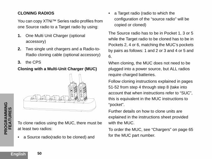
ESCLONING RADIOS
You can copy XTNi™one Source radio to a
1. One Multi Unit Caccessory)
2. Two single unit cRadio cloning ca
3. the CPSCloning with a Mult
To clone radios usingat least two radios:
• a Source radio(rad
Series radio profiles from Target radio by using:
harger (optional
hargers and a Radio-to-ble (optional accessory)
i-Unit Charger (MUC)
• a Target radio (radio to which the configuration of the “source radio” will be copied or cloned)
The Source radio has to be in Pocket 1, 3 or 5 while the Target radio to be cloned has to be in Pockets 2, 4 or 6, matching the MUC’s pockets by pairs as follows: 1 and 2 or 3 and 4 or 5 and 6.When cloning, the MUC does not need to be plugged into a power source, but ALL radios require charged batteries. Follow cloning instructions explained in pages
the MUC, there must be
io to be cloned) and
51-52 from step 4 through step 8 (take into account that when instructions refer to “SUC”, this is equivalent in the MUC instructions to “pocket”. Further details on how to clone units are explained in the instructions sheet provided with the MUC.To order the MUC, see “Chargers” on page 65 for the MUC part number.

51 English
PRO
GR
AM
MIN
G
FEATU
RES
on each one of the
ers (SUC). and,same radio model.ower supply or USB
loning cable mini Plug the other end
rocess no power is The batteries will mmunication is the two radios.
adio and place it
power the radio below:tton and SB2
rning the radio ON. fore releasing the e audible tone is heard.
Cloning Radio using the Radio to Radio (R2R) Cloning Cable (optional accessory)
Operating Instructions1. Before beginning the cloning process, make sure you have:
• A fully charged batteryradios.• Two Single Unit Charg• Turned OFF the radios• Both radios are of the 2. Unplug any cables (pcables) from the SUCs.3. Plug one side of the cconnector to one SUC. to the second SUC.Note: During the cloning pbeing applied to the SUC.not be charged. A data cobeing established between4. Turn ON the Target rinto one of the SUCs.5. On the Source radio,following the sequence • Long press the PTT busimaltaneously while tu• Wait for 3 seconds bebuttons until a distinctiv
Paired target radios and source radios must be of the same band (UHF or VHF), type (Display or non-Display) and region.
!W A R N I N G
!

PRO
GR
AM
MIN
G
ries on both radios are
ble connection on both
ry is engaged properly
o debris in the radio contacts.ce radio is in cloning
t radio is turned ON.re both from the same and, same front panel me region and same
ble is designed to le Motorola nit Charger.
Cable please refer to ils about accessories ection.
52 English
FEA
TUR
ES6. Place the Source radio” in its SUC, press and release SB1.7. After cloning is completed, the Source radio will sound either a “pass” tone (cloning was successful) or a “fail” tone (cloning process has failed). The ‘pass’ tone sounds like a good key ‘chirp’ whereas the ‘fail’ tone sounds similar to a ‘bonk’ tone. If the Source radio is a display model it will either show ‘Pass’ or ‘Fail’ on the display (a tone will be heard in no more than 5 seconds).8. Once you have completed the cloning process, turn the radios OFFand ON in order to exit ‘clone’ mode.
What to do if cloning fails
The radio will emit an audible ‘bonk’ indicating that the cloning process has failed. In the event that cloning fails, try performing each of the following before trying to start the cloning process again:
1. Ensure that the battefully charged.2. Check the cloning caSUCs.3. Ensure that the batteon to the radio.4. Ensure that there is ncharging tray or on the 5. Ensure that the Sourmode.6. Ensure that the Targe7. Ensure both radios atype. (same frequency b(display/non display), satransmission power).Attention: This cloning caoperate only with compatibRLN6170 (Rapid) Single U
When ordering Cloning P/N RLN6303. For detarefer to “Accessories” s

53 English
PRO
GR
AM
MIN
G
FEATU
RES
To order the CPS, see ‘Software Applications on page 64’ for the CPS part number.Cloning Radios using the CPS (Computer Programming Software)You will need to have the CPS, Drop-in Tray Charger and the CPS Programming Cable.Information on how to clone using the CPS is available in the CPS Programming Cable Accessory Leaflet as well as the CPS Help menu.
Note: (*) CPS Programming Cable is an accessory sold separately. For part number information refer to the Accessories Section.

TRO
UB
LESH
OO
TIN
G
or reposition AA ffect battery life. Refer
requency or Change Code on all
oes not match other ble L" on page 41.
e, buildings or of sight to improve h as in a pocket or on dio. Refer to "Talking
54English
TROUBLESHOOTING
Symptom Try this
No PowerRecharge or replace Li-Ion battery. Replace batteries. Extreme operating temperatures ato "About the Li-Ion Battery" on page 12.
Hearing other noises or conversation on a channel
Confirm Interference Eliminator Code is set. FInterference Eliminator Code may be in use. radios if possible.
Message ScrambledScramble Code might be ON, and/or setting dradios' settings. Refer to "Programming Scram
Limited talk range
Steel and/or concrete structures, heavy foliagvehicles decrease range. Check for clear linetransmission. Wearing radio close to body suca belt decreases range. Change location of raand Monitoring" on page 27.

55 English
TRO
UB
LESHO
OTIN
G
uency, Interference . Recharge, replace
the Li-Ion Battery" on , or in vehicles, may nd Monitoring" on ode. Refer to
uisance Channel
e feet apart. Radios ith transmission.
.
A batteries. Extreme er to "About the Li-Ion
check battery/charger ing pin is inserted age 19, "Drop-in Tray talling the Lithium-Ion
ry type. Refer to page 14, "Installing i-Ion Battery" on page
Message not transmitted/ received
Confirm radios have the same Channel, FreqEliminator Code and Scramble Code settingsand/or reposition batteries. Refer to ""About page 12. Obstructions and operating indoorsinterfere: change location. Refer to "Talking apage 27. Verify that the radio is not in Scan m"Programming Scan List" on page 44 and "NDelete" on page 47.
Heavy static or interferenceRadios are too close, they must be at least fivare too far apart or obstacles are interfering wRefer to "Talking and Monitoring" on page 27
Low batteriesRecharge or replace Li-Ion battery. Replace Aoperating temperatures affect battery life. RefBattery" on page 12.
Drop-in Charger LED light does not come on
Check radio/battery is properly inserted and contacts to be sure they are clean and chargcorrectly. Refer to "Charging the Battery" on pCharger LED Indicators" on page 23 and "Ins(Li-Ion) Battery" on page 14.
Low battery LED blinking although new batteries are installed
Verify that the radio is set to the correct batte"Installing the Lithium-Ion (Li-Ion) Battery" onAlkaline Battery" on page 15 and "About the L12.
Symptom Try this

TRO
UB
LESH
OO
TIN
G
X Sensitivity might be tible. Refer to "Hands-
espond to a e drop-in charger (refer to "Charging page 19 and ). Check the charger m. Refer to ""Drop-in
ecial software can set ur radio seems not to our radio have been
56English
Cannot activate VOXVOX feature might not have been set ON. VOset to 0. Accessory not working or not compaFree Use/VOX" on page 31.
Battery doesn't charge although it has been placed in the drop-in charger for a while
Check drop-in charger is connected and corrcompatible power supply. Check you have thadjustable piece, placed on the right positionwith the Drop-in Tray Single Unit Charger" on"Charging a Stand-Alone Battery" on page 20LEDs indicators to see if battery has a probleTray Charger LED Indicators" on page 23.
Note: XTNi™ series radios can be programmed using CPS software. This spup features or restrict values in your radio. Whenever a feature in yocorrespond to the default or preprogrammed values, find out if yprogrammed using CPS with a customized profile.
Symptom Try this

57 English
USE A
ND
CA
RE
USE AND CARE
Use a soft damp clothto clean the exterior
Do not immersein water
Do not use alcohol orcleaning solutions
Turn radio OFF andremove batteries
Dry with soft cloth Do not use radio untilcompletely dry
If the radio is submerged in water...

English
FREQ
UEN
CY
AN
D
i™ Series two-way radios. Most of the same as Spirit M,
encies.
58 English
CO
DE
CH
AR
TS
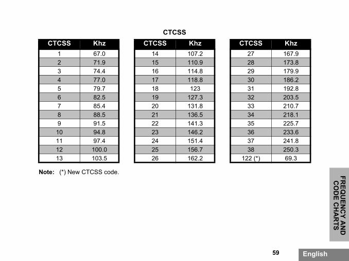
FREQUENCY AND CODE CHARTS
The charts in this section provide Frequency and Code information. These charts are useful
when using Motorola XTNradios with other businessfrequency position are theGT, S, XTN Series Frequ
8 Channel Radios PMR 446 DefaultsFreq # Frequency Code Bandwidth
1 446.00625 67.0 Hz 12.5kHz2 446.01875 67.0 Hz 12.5kHz3 446.03125 67.0 Hz 12.5kHz4 445.04375 67.0 Hz 12.5kHz5 446.05625 67.0 Hz 12.5kHz6 446.06875 67.0 Hz 12.5kHz7 446.08125 67.0 Hz 12.5kHz8 446.09375 67.0 Hz 12.5kHz9 446.00625 754.0 Hz 12.5kHz
10 446.01875 754.0 Hz 12.5kHz11 446.03125 754.0 Hz 12.5kHz12 445.04375 754.0 Hz 12.5kHz13 446.05625 754.0 Hz 12.5kHz14 446.06875 754.0 Hz 12.5kHz15 446.08125 754.0 Hz 12.5kHz16 446.09375 754.0 Hz 12.5kHz
Note: Code 754 corresponds to PL Code 121.
59 English
FREQ
UEN
CY A
ND
C
OD
E CH
AR
TS
SS Khz7 167.98 173.89 179.90 186.21 192.82 203.53 210.74 218.15 225.76 233.67 241.88 250.3 (*) 69.3
CTCSS CTCSS Khz CTCSS Khz CTC
1 67.0 14 107.2 22 71.9 15 110.9 23 74.4 16 114.8 24 77.0 17 118.8 35 79.7 18 123 36 82.5 19 127.3 37 85.4 20 131.8 38 88.5 21 136.5 39 91.5 22 141.3 310 94.8 23 146.2 311 97.4 24 151.4 312 100.0 25 156.7 313 103.5 26 162.2 122
Note: (*) New CTCSS code.

English
FREQ
UEN
CY
AN
D
L Code
343
346
351
364
365
371
411
412
413
423
431
432
445
464
465
466
503
0 506
60 English
CO
DE
CH
AR
TS
DPL Codes (cont.)
DPL Code DPL Code DP
39 23 61 152 83
40 25 62 155 84
41 26 63 156 85
42 31 64 162 86
43 32 65 165 87
44 43 66 172 88
45 47 67 174 89
46 51 68 205 90
47 54 69 223 91
48 65 70 226 92
49 71 71 243 93
50 72 72 244 94
51 73 73 245 95
52 74 74 251 96
53 114 75 261 97
54 115 76 263 98
55 116 77 265 99
56 125 78 271 10

61 English
FREQ
UEN
CY A
ND
C
OD
E CH
AR
TS
01 516
02 532
03 546
04 565
19 734
20 743
21 754
PL Code
57 131 79 306 1
58 132 80 311 1
59 134 81 315 1
60 143 82 331 1
105 606 112 662 1
106 612 113 664 1
107 624 114 703 1
108 627 115 712
109 631 116 723
110 632 117 731
111 654 118 732
DPL Codes (cont.)
DPL Code DPL Code D

MO
TOR
OLA
LIM
ITED
ED BY THE
esulting from use of the its normal and r by not following the er manual.
rom misuse, accident
rom improper testing, ce, adjustment, or any tion of any kind.
to aerials unless efects in material or
led or repaired in such rsely affect ent adequate g to verify any
62English
WA
RR
AN
TY
MOTOROLA LIMITED WARRANTY
WARRANTY INFORMATION
The authorised Motorola dealer or retailer where you purchased your Motorola two-way radio and/or original accessories will honour a warranty claim and/or provide warranty service. Please return your radio to your dealer or retailer to claim your warranty service. Do not return your radio to Motorola. To be eligible to receive warranty service, you must present your receipt of purchase or a comparable substitute proof of purchase bearing the date of purchase. The two-way radio should also clearly display the serial number. The warranty will not apply if the type or serial numbers on the product have been altered, deleted, removed, or made illegible.
WHAT IS NOT COVERWARRANTY
• Defects or damage rProduct in other thancustomary manner oinstructions in this us
• Defects or damage for neglect.
• Defects of damage foperation, maintenanalteration or modifica
• Breakage or damagecaused directly by dworkmanship.
• Products disassemba manner as to adveperformance or previnspection and testinwarranty claim.

63 English
MO
TOR
OLA
LIMITED
W
AR
RA
NTY
temporary basis.
e and repair or due to normal usage,
• Defects or damage due to range.
• Defects or damage due to moisture, liquid or spills.
• All plastic surfaces and all other externally exposed parts that are scratched or damaged due to normal use.
• Products rented on a
• Periodic maintenancreplacement of partswear and tear.
AC
CES
SOR
IES
S
TIONS
Description
her Carry Case
ion Belt Clip
Description
Programming Software Programming Cable
Description
adio Cloning Cable
64English
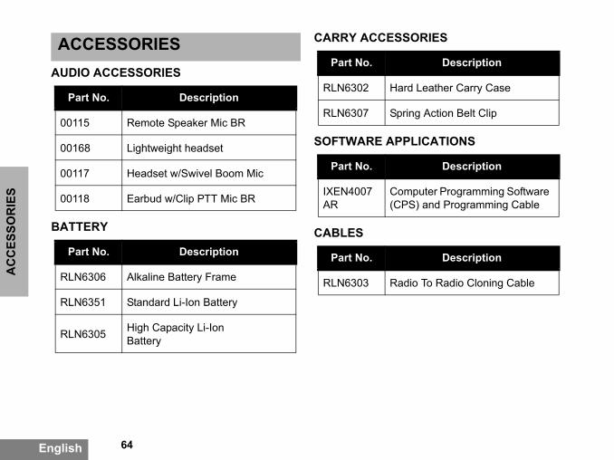
ACCESSORIESAUDIO ACCESSORIES
BATTERY
CARRY ACCESSORIE
SOFTWARE APPLICA
CABLES
Part No. Description
00115 Remote Speaker Mic BR
00168 Lightweight headset
00117 Headset w/Swivel Boom Mic
00118 Earbud w/Clip PTT Mic BR
Part No. Description
RLN6306 Alkaline Battery Frame
RLN6351 Standard Li-Ion Battery
RLN6305 High Capacity Li-Ion Battery
Part No.
RLN6302 Hard Leat
RLN6307 Spring Act
Part No.
IXEN4007AR
Computer(CPS) and
Part No.
RLN6303 Radio To R

65 English
AC
CESSO
RIES
ssories may be or may e of purchase. Please t of purchase or visit r www.motorola.com/ nformation on
ging Kit includes Power ger, and AC Pin adaptors.horized dealer for s new models information
CHARGERS Note:(*) Attention: Certain accenot be available at the timcontact your Motorola poinwww.motorola.com/XTNi oradios/business for latest iaccessories.(**) European Rapid CharSupply, Drop-in Tray CharContact your Motorola autavailability and accessorie
Part No. Description
IXPN4019AR
Rapid Charging Kit - European (**)
IXPN4020AR
Multi-Unit Charger (MUC) Kit - European


and all other trademarks indi- Inc. ® Reg. U.S. Pat. & Tm. Off. ty of their respective owners. © served. Printed in the U.S.A.
MOTOROLA, the Stylized M Logo,XTNi™ Series cated as such herein are trademarks of Motorola,All other product or service names are the proper2001, 2002, 2005, 2007 Motorola, Inc. All rights reMotorola® XTNi™ Series
*6871663M05*6871663M05-A