movingfloor - dimento
TRANSCRIPT

MovingFloor®
Bunker Systems

Product description MovingFloor®
Perfect down to the last detail. This is how you could describe the Westeria® MovingFloor® with its well thought out building kit principle. The intelligently and cost effectively structured series offers the highest flexibility within the standard product range. The principle enables the MovingFloor® to be
expanded and/or expanded at any time. The pre-finished modules enable delivery times within 5 weeks. The areas of use for the MovingFloor® are also extremely flexible. From the processing of substitute fuel to compost, right up to building rubble, anything is possible.

Advantages
Statics
Three available series offer the right bunker for every material: · Light design up to 0.3 t / m³ · Medium design up to 0.6 t / m³ · Heavy design up to 1.2 t / m³
Various wall designs available: galvanized or optionally stainless steel, Hardox or painted
All floor assemblies and rod types are set up statically for HGV navigability
Performance
The whole system is strictly conceived according to the building kit principle
All bunker models can be quickly and easily disassembled into their individual modules, making it possible to be shipped in a standard ISO sea container
Prefabricated components and parts minimise the delivery period to just 5 weeks
Due to the modular construction the bunker can be flexibly extended and therefore has a high value retention
Bunker volume range from 20 m³ to 480 m³ from the same construction elements
Standard variants can be provided for integration into the concrete bunker
Minimum material loss due to optimised Westeria® coating system
Using the special Westeria® timing system
and optional discharge dosing roller produces an extremely even dosage
Optimum usage width in relation to the outer width
Optional fully automatic bunker loading system available
Hydraulics
From light to heavy – five different hydraulic cylinder types allow the selection of an optimal piston diameter for every application, with up to 4000 KN pressing force!
For every discharge performance required, you can choose the right hydraulic pump from four standard sizes available from 7.5 to 22 KW driving power
Dosage drum
The optional dosing roller ensures even material output even with a full bunker load
The special Westeria® sealing system prevents material jams between the casing wall and the drum
Maintenance
Minimum wear and tear costs due to omission of bearings, shafts, chains or conveyor belts
Due to the drive concept without limit switch, the bunker is very robust
Large maintenance doors in every head module
Assembly
Very short assembly times due to standardised components, produced with the smallest tolerances
The simple building kit system with perfect installation instructions enables assembly without specialist personnel
Provision with complete pre-assembled hydraulic component
Large diameter of at least 1000 mm prevents material getting wrapped round it
Various driver tools for optimum function with a variety of materials
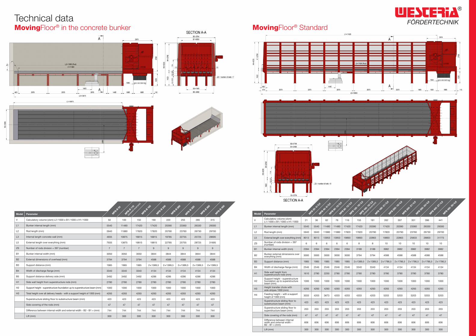
Technical dataMovingFloor® in the concrete bunker
Model Parameter
V Calculatory volume (cbm) L2 / 1000 x B1 / 1000 x H1 / 1000 50 100 150 190 220 255 285 315
L1 Bunker internal length (mm) 5540 11480 17420 17420 20390 23360 26330 29300
L2 Rod length (mm) 5940 11880 17820 17820 20790 23760 26730 29700
L3 Internal length concrete wall (mm) 4935 10875 16815 16815 19785 22755 25725 28695
L5 External length over everything (mm) 7935 13875 19815 19815 22785 25755 28725 31695
ZS Number of rods division = 397 (number) 7 7 7 9 9 9 9 9
B1 Bunker internal width (mm) 3050 3050 3050 3844 3844 3844 3844 3844
B2 External dimensions of overhead (mm) 3794 3794 3794 4588 4588 4588 4588 4588
B3 Support distance (mm) 1985 1985 1985 2 x 1389,5 2 x 1389,5 2 x 1389,5 2 x 1389,5 2 x 1389,5
B4 Width of discharge flange (mm) 3340 3340 3340 4134 4134 4134 4134 4134
B5 Support distance delivery side (mm) 3492 3492 3492 4286 4286 4286 4286 4286
H1 Side wall height from superstructure rods (mm) 2780 2780 2780 2780 2780 2780 2780 2780
H2 Support height - superstructure foundation up to superstructure beam (mm) 1000 1000 1000 1000 1000 1000 1000 1000
H3 Total height over all delivery heads - with a support height of 1000 (mm) 4293 4293 4293 4293 4293 4293 4293 4293
Superstructure sliding floor to substructure beam (mm) 423 423 423 423 423 423 423 423
Side covering of the rods (mm) 47 47 47 47 47 47 47 47
Difference between internal width and external width - B2 - B1 = (mm) 744 744 744 744 744 744 744 744
Lift (mm) 300 300 300 300 300 300 300 300
Model Parameter
VCalculatory volume (cbm) L1 / 1000 x B1 / 1000 x H1 / 1000
21 36 62 76 116 155 181 262 307 351 396 441
L1 Bunker internal length (mm) 5540 5540 11480 11480 17420 17420 20390 17420 20390 23360 26330 29300
L2 Rod length (mm) 5940 5940 11880 11880 17820 17820 20790 17820 20790 23760 26730 29700
L5 External length over everything (mm) 8013 8013 13953 13953 19893 19893 22863 19893 22863 25833 28803 31773
ZS Number of rods division = 397 (number) 6 6 6 6 6 8 8 10 10 10 10 10
B1 Bunker internal width (mm) 2394 2394 2394 2394 2394 3188 3188 3982 3982 3982 3982 3982
B2 Bunker external dimensions over everything (mm) 3000 3000 3000 3000 3000 3794 3794 4588 4588 4588 4588 4588
B3 Support distance (mm) 1985 1985 1985 1985 1985 2 x 1389,5 2 x 1389,5 2 x 1786,5 2 x 1786,5 2 x 1786,5 2 x 1786,5 2 x 1786,5
B4 Width of discharge flange (mm) 2546 2546 2546 2546 2546 3340 3340 4134 4134 4134 4134 4134
H1 Side wall height from superstructure rods (mm) 1610 2780 2250 2780 2780 2780 2780 3780 3780 3780 3780 3780
H2Support height - superstructure foundation up to superstructure beam (mm)
1000 1000 1000 1000 1000 1000 1000 1000 1000 1000 1000 1000
H3Height transfer chute withside stripes 1000 (mm)
4293 4293 4293 4293 4293 4293 4293 4293 4293 4293 4293 4293
H4 Feeding height – with a support height of 1000 (mm)
3033 4203 3673 4203 4203 4203 4203 5203 5203 5203 5203 5203
Superstructure sliding floor to substructure beam (mm)
423 423 423 423 423 423 423 423 423 423 423 423
Superstructure sliding floor to superstructure beam (mm)
203 203 203 203 203 203 203 203 203 203 203 203
Side covering of the rods (mm) 47 47 47 47 47 47 47 47 47 47 47 47
Difference between internal width and external width - B2 - B1 = (mm)
606 606 606 606 606 606 606 606 606 606 606 606
Lift (mm) 300 300 300 300 300 300 300 300 300 300 300 300
MFB
-B 55
MFB
20 - 6
/ 3,0
MFB
40 - 6
/ 3,0
MFB
60 - 1
2 / 3,
0
MFB
80 - 1
2 / 3,
0
MFB
120 -
18 / 3
,0
MFB
160 -
18 / 3
,8
(d
rawed
exam
ple)
MFB
180 -
21 / 3
,8
MFB
250 -
18 / 4
,6
MFB
300 -
21 / 4
,6
MFB
350 -
24 / 4
,6
MFB
400 -
27 / 4
,6
MFB
480 -
30 / 4
,6
MFB
-B 11
0
(dra
wed ex
ample)
MFB
-B 16
5
MFB
-B 24
0
MFB
-B 28
0
MFB
-B 32
0
MFB
-B 36
0
MFB
-B 40
0
MovingFloor® Standard

Westeria® conveys values
Production, logistics, recycling – when conveying general loads or bulk material and in case of separating and sorting mixed valuable substances and materials: special solutions are necessary – they have to be economi-cal, solid, lasting, reliable and made for special requirements.
Westeria® Fördertechnik GmbHRaiffeisenstr. 2D-48346 Ostbevern
Fon +49 (0) 25 32/88-0Fax +49 (0) 25 32/77 70