mpls tutorial peter ashwood-smith bilel n. jamoussi [email protected]...
Post on 19-Dec-2015
215 views
TRANSCRIPT
MPLS TutorialMPLS Tutorial
Peter Ashwood-SmithPeter Ashwood-SmithBilel N. JamoussiBilel N. Jamoussi
[email protected]@[email protected]@nortelnetworks.com

2
Copyright © 1999, Nortel Networks, Ltd. BNJ+PAS
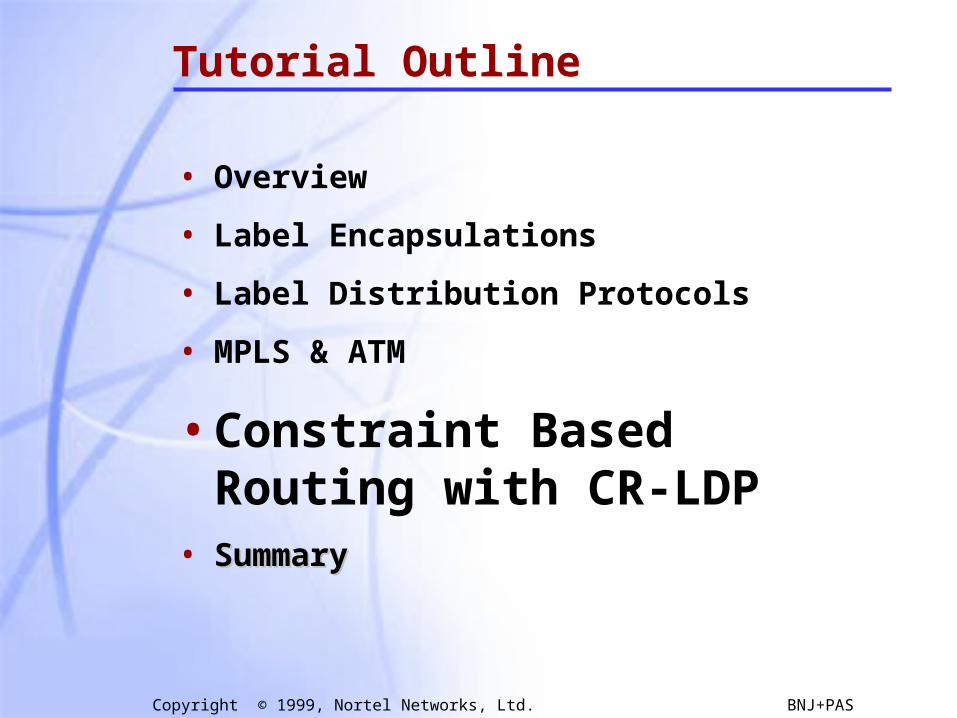
Tutorial Outline
• OverviewOverview• Label Encapsulations
• Label Distribution Protocols
• MPLS & ATM
• Constraint Based Routing with CR-LDP
• Summary

3
Copyright © 1999, Nortel Networks, Ltd. BNJ+PAS
“Label Substitution” what is it?
•BROADCAST: Go everywhere, stop when you get to B, never ask for directions.
•HOP BY HOP ROUTING: Continually ask who’s closer to B go there, repeat … stop when you get to B.
“Going to B? You’d better go to X, its on the way”.
•SOURCE ROUTING: Ask for a list (that you carry with you) of places to go that eventually lead you to B.
“Going to B? Go straight 5 blocks, take the next left, 6 more blocks and take a right at the lights”.
One of the many ways of getting from A to B:
4
Copyright © 1999, Nortel Networks, Ltd. BNJ+PAS
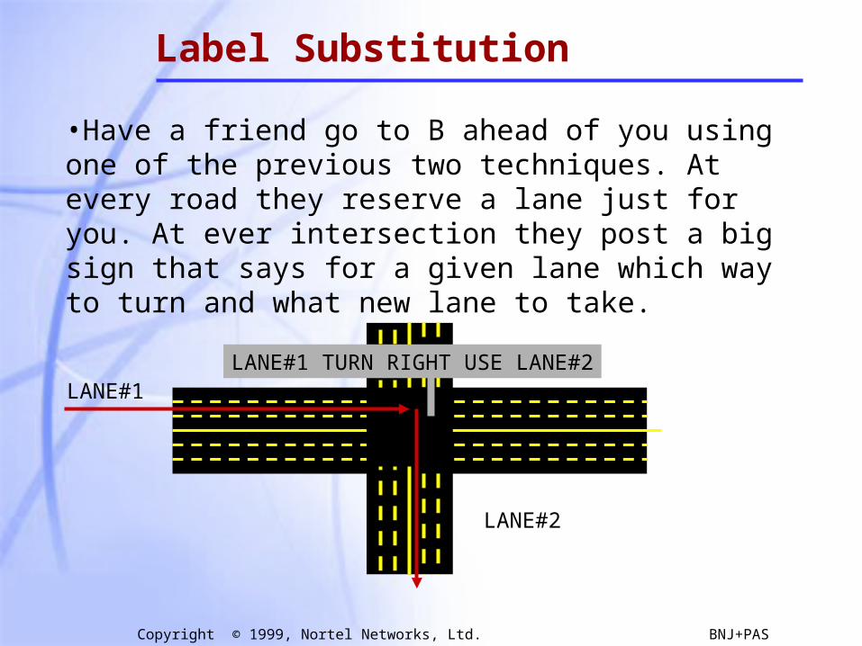
Label Substitution
•Have a friend go to B ahead of you using one of the previous two techniques. At every road they reserve a lane just for you. At ever intersection they post a big sign that says for a given lane which way to turn and what new lane to take.
LANE#1
LANE#2
LANE#1 TURN RIGHT USE LANE#2
5
Copyright © 1999, Nortel Networks, Ltd. BNJ+PAS
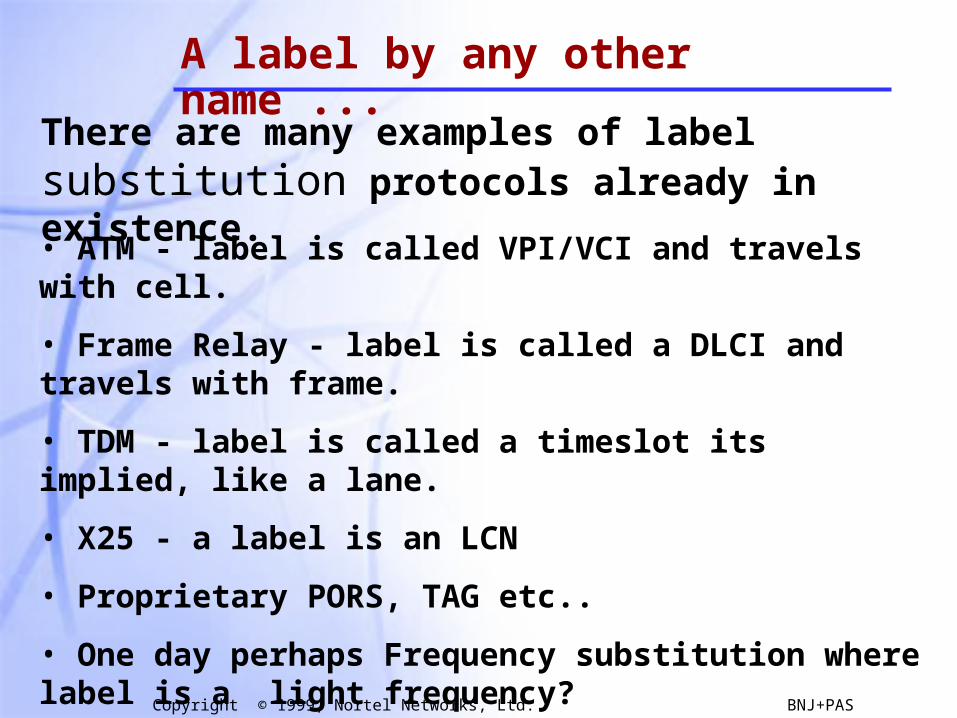
A label by any other name ...
There are many examples of label substitution protocols already in existence.
• ATM - label is called VPI/VCI and travels with cell.
• Frame Relay - label is called a DLCI and travels with frame.
• TDM - label is called a timeslot its implied, like a lane.
• X25 - a label is an LCN
• Proprietary PORS, TAG etc..
• One day perhaps Frequency substitution where label is a light frequency?
6
Copyright © 1999, Nortel Networks, Ltd. BNJ+PAS
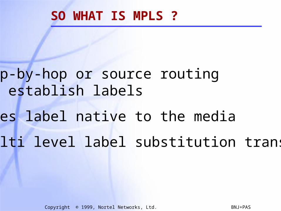
SO WHAT IS MPLS ?
• Hop-by-hop or source routing to establish labels
• Uses label native to the media
• Multi level label substitution transport

7
Copyright © 1999, Nortel Networks, Ltd. BNJ+PAS
ROUTE AT EDGE, SWITCH IN CORE
IP ForwardingLABEL SWITCHINGIP Forwarding
IP IP #L1 IP #L2 IP #L3 IP

8
Copyright © 1999, Nortel Networks, Ltd. BNJ+PAS
MPLS: HOW DOES IT WORK
UDP-Hello
UDP-Hello
TCP-open
TIME
TIME
Label requestIP
Label mapping#L2
Initialization(s)

9
Copyright © 1999, Nortel Networks, Ltd. BNJ+PAS
WHY MPLS ?
• Leverage existing ATM hardware
• Ultra fast forwarding
• IP Traffic Engineering—Constraint-based Routing
• Virtual Private Networks—Controllable tunneling mechanism
• Voice/Video on IP—Delay variation + QoS constraints
10
Copyright © 1999, Nortel Networks, Ltd. BNJ+PAS
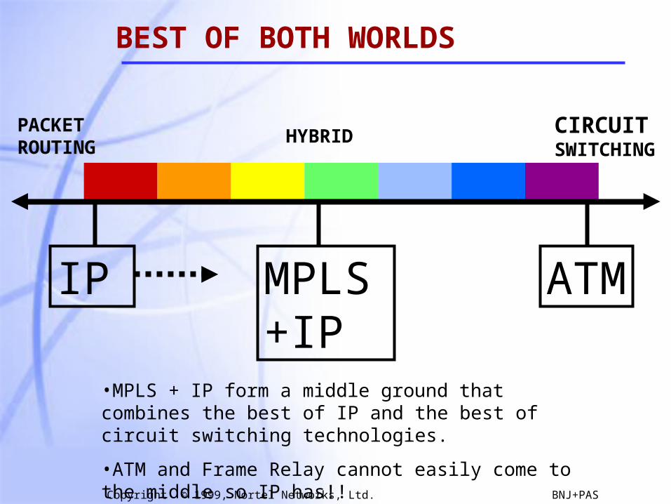
BEST OF BOTH WORLDS
PACKETROUTING
CIRCUITSWITCHING
•MPLS + IP form a middle ground that combines the best of IP and the best of circuit switching technologies.
•ATM and Frame Relay cannot easily come to the middle so IP has!!
MPLS+IP
IP ATM
HYBRID
11
Copyright © 1999, Nortel Networks, Ltd. BNJ+PAS
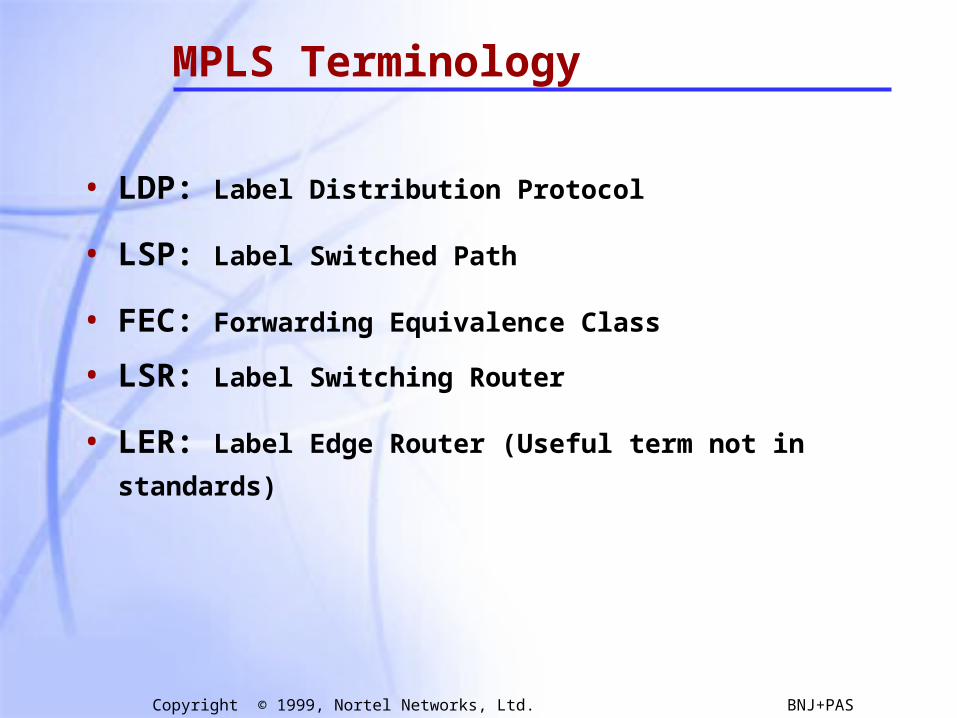
MPLS Terminology
• LDP: Label Distribution Protocol
• LSP: Label Switched Path
• FEC: Forwarding Equivalence Class
• LSR: Label Switching Router
• LER: Label Edge Router (Useful term not in standards)

12
Copyright © 1999, Nortel Networks, Ltd. BNJ+PAS
Forwarding Equivalence Classes
• FEC = “A subset of packets that are all treated the same way by a router”
• The concept of FECs provides for a great deal of flexibility and scalability
• In conventional routing, a packet is assigned to a FEC at each hop (i.e. L3 look-up), in MPLS it is only done once at the network ingress
Packets are destined for different address prefixes, but can bemapped to common pathPackets are destined for different address prefixes, but can bemapped to common path
IP1
IP2
IP1
IP2
LSRLSRLER LER
LSP
IP1 #L1
IP2 #L1
IP1 #L2
IP2 #L2
IP1 #L3
IP2 #L3
13
Copyright © 1999, Nortel Networks, Ltd. BNJ+PAS
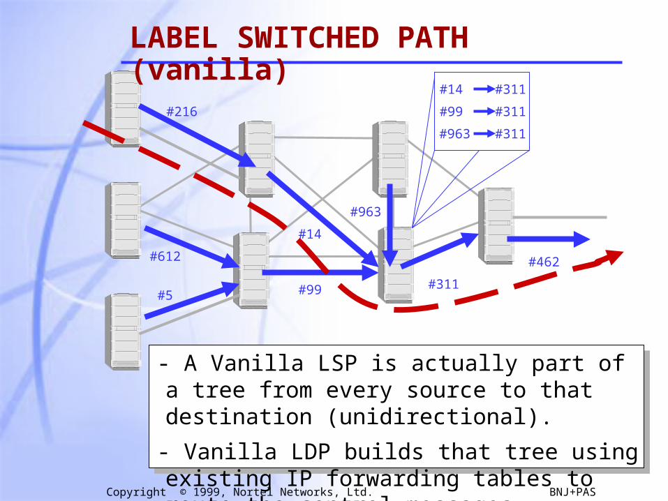
#216
#612
#5#311
#14
#99
#963
#462
- A Vanilla LSP is actually part of a tree from every source to that destination (unidirectional).
- Vanilla LDP builds that tree using existing IP forwarding tables to route the control messages.
#963
#14
#99
#311
#311
#311
LABEL SWITCHED PATH (vanilla)
14
Copyright © 1999, Nortel Networks, Ltd. BNJ+PAS
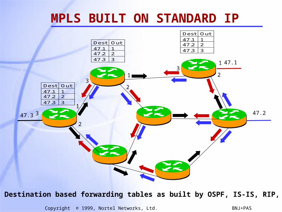
MPLS BUILT ON STANDARD IP
47.1
47.247.3
Dest Out
47.1 147.2 2
47.3 3
1
23
Dest Out
47.1 147.2 2
47.3 3
Dest Out
47.1 147.2 2
47.3 3
1
23
1
2
3
• Destination based forwarding tables as built by OSPF, IS-IS, RIP, etc.
15
Copyright © 1999, Nortel Networks, Ltd. BNJ+PAS
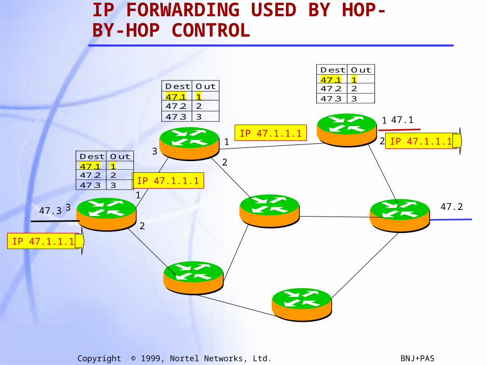
IP FORWARDING USED BY HOP-BY-HOP CONTROL
47.1
47.247.3
IP 47.1.1.1
Dest Out
47.1 147.2 2
47.3 3
1
23
Dest Out
47.1 147.2 2
47.3 3
1
2
1
2
3
IP 47.1.1.1
IP 47.1.1.1IP 47.1.1.1
Dest Out
47.1 147.2 2
47.3 3
16
Copyright © 1999, Nortel Networks, Ltd. BNJ+PAS
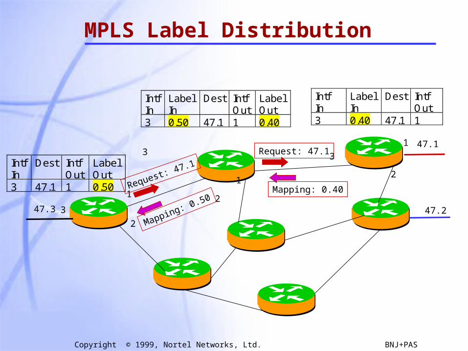
IntfIn
LabelIn
Dest IntfOut
3 0.40 47.1 1
IntfIn
LabelIn
Dest IntfOut
LabelOut
3 0.50 47.1 1 0.40
MPLS Label Distribution
47.1
47.247.3
1
2
31
2
1
2
3
3IntfIn
Dest IntfOut
LabelOut
3 47.1 1 0.50 Mapping: 0.40
Request: 47.1
Mapping: 0.50
Request: 47.1
17
Copyright © 1999, Nortel Networks, Ltd. BNJ+PAS
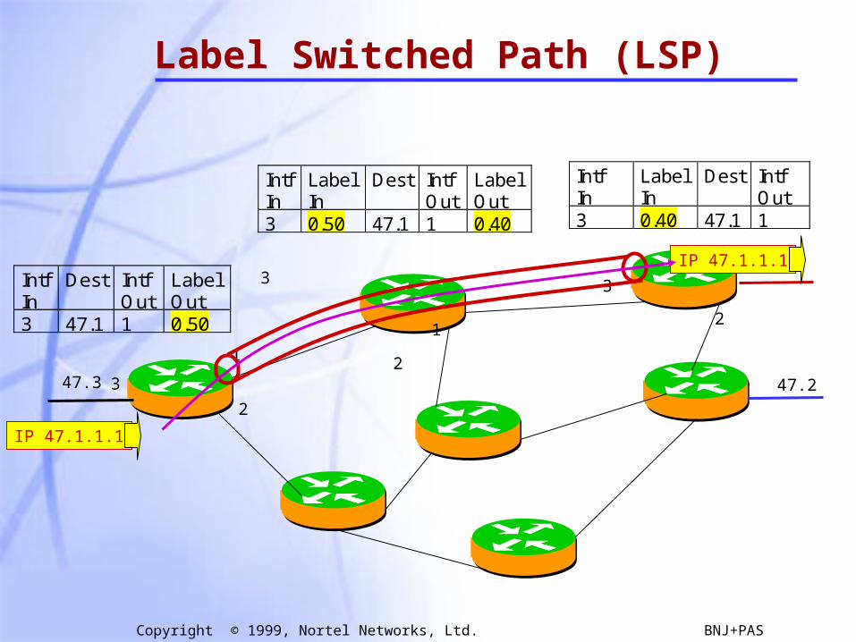
Label Switched Path (LSP)
IntfIn
LabelIn
Dest IntfOut
3 0.40 47.1 1
IntfIn
LabelIn
Dest IntfOut
LabelOut
3 0.50 47.1 1 0.40
47.1
47.247.3
1
2
31
2
1
2
3
3IntfIn
Dest IntfOut
LabelOut
3 47.1 1 0.50
IP 47.1.1.1
IP 47.1.1.1

18
Copyright © 1999, Nortel Networks, Ltd. BNJ+PAS
#216
#14
#462
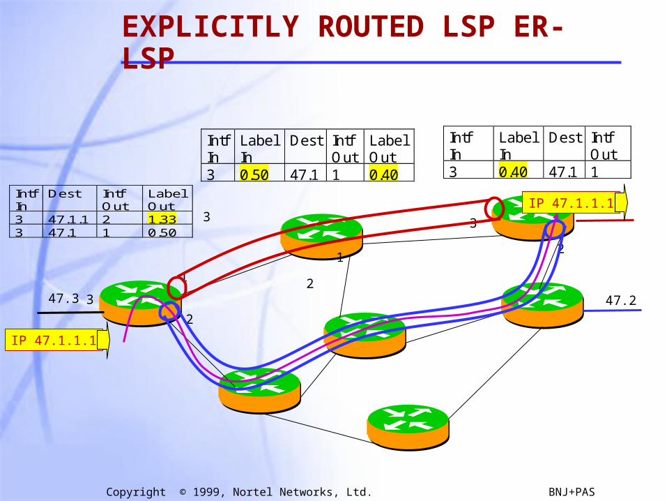
- ER-LSP follows route that source chooses. In other words, the control message to establish the LSP (label request) is source routed.
#972
#14 #972
A
B
C
Route={A,B,C}
EXPLICITLY ROUTED OR ER-LSP
19
Copyright © 1999, Nortel Networks, Ltd. BNJ+PAS
IntfIn
LabelIn
Dest IntfOut
3 0.40 47.1 1
IntfIn
LabelIn
Dest IntfOut
LabelOut
3 0.50 47.1 1 0.40
47.1
47.247.3
1
2
31
2
1
2
3
3
IntfIn
Dest IntfOut
LabelOut
3 47.1.1 2 1.333 47.1 1 0.50
IP 47.1.1.1
IP 47.1.1.1
EXPLICITLY ROUTED LSP ER-LSP
20
Copyright © 1999, Nortel Networks, Ltd. BNJ+PAS
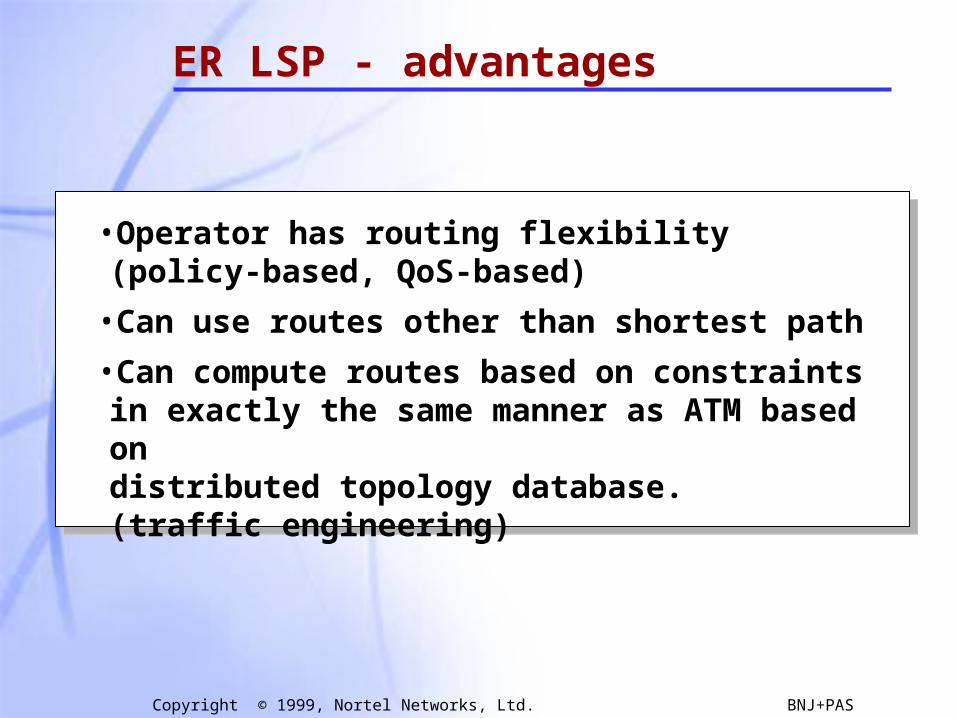
ER LSP - advantages
•Operator has routing flexibility (policy-based, QoS-based)
•Can use routes other than shortest path
•Can compute routes based on constraints in exactly the same manner as ATM based on distributed topology database.(traffic engineering)
21
Copyright © 1999, Nortel Networks, Ltd. BNJ+PAS
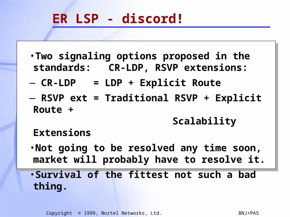
ER LSP - discord!
•Two signaling options proposed in the standards: CR-LDP, RSVP extensions:
— CR-LDP = LDP + Explicit Route
— RSVP ext = Traditional RSVP + Explicit Route + Scalability Extensions
•Not going to be resolved any time soon, market will probably have to resolve it.
•Survival of the fittest not such a bad thing.
22
Copyright © 1999, Nortel Networks, Ltd. BNJ+PAS
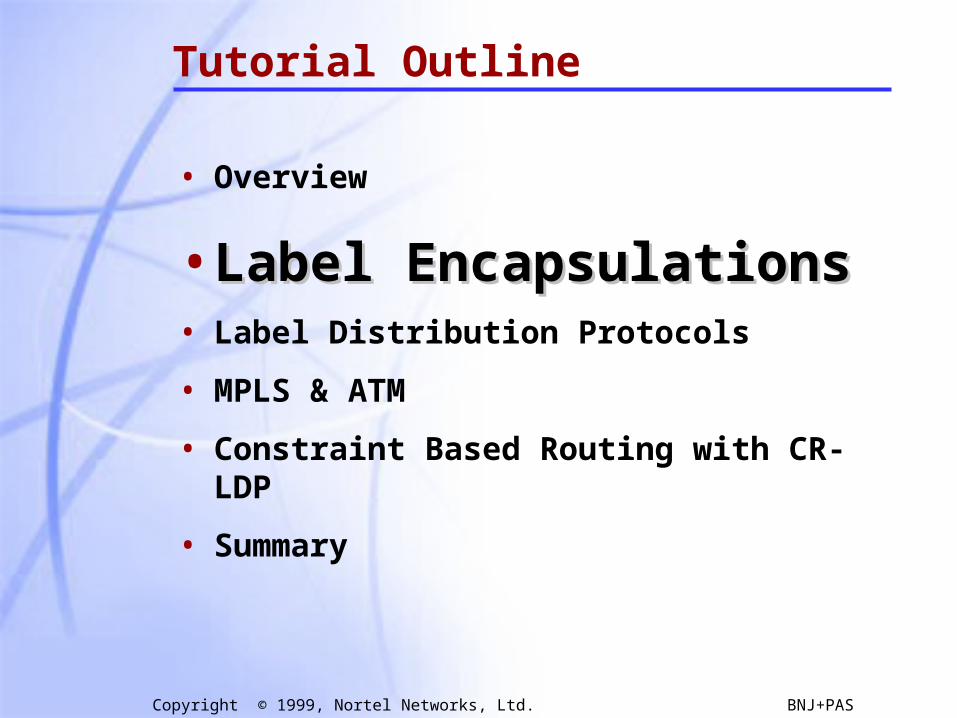
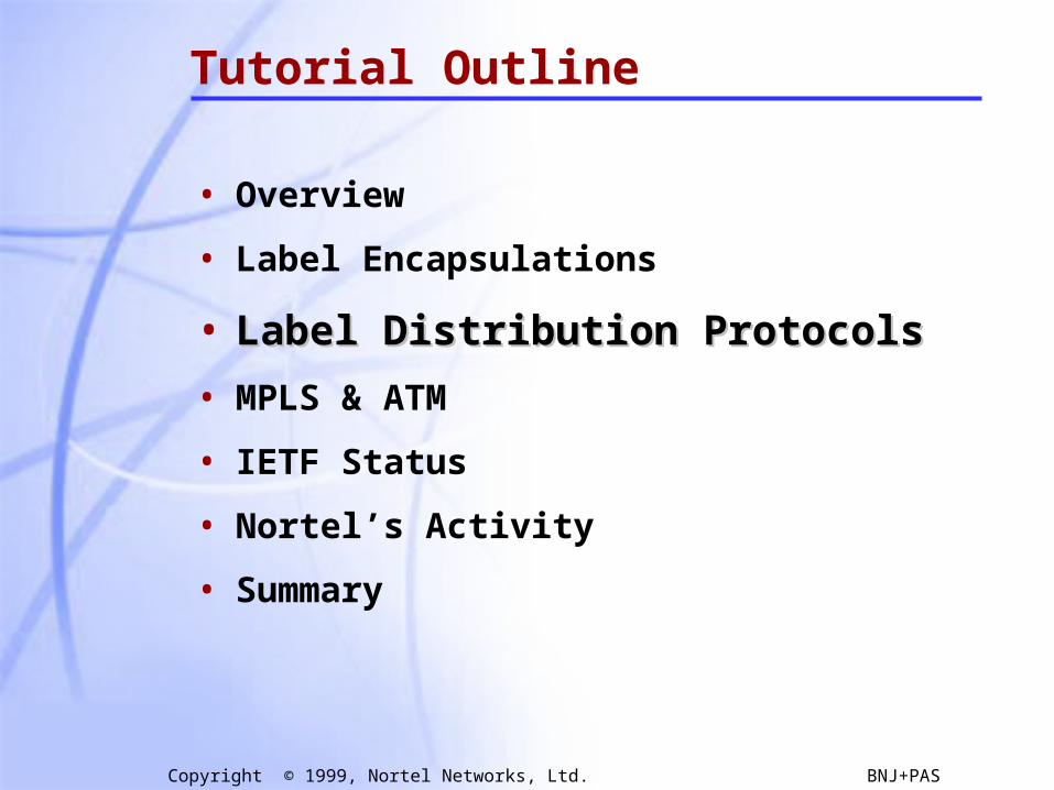
Tutorial Outline
• Overview
• Label EncapsulationsLabel Encapsulations• Label Distribution Protocols
• MPLS & ATM
• Constraint Based Routing with CR-LDP
• Summary
23
Copyright © 1999, Nortel Networks, Ltd. BNJ+PAS
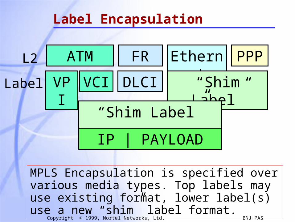
Label Encapsulation
ATM FR Ethernet PPP
MPLS Encapsulation is specified over various media types. Top labels may use existing format, lower label(s) use a new “shim” label format.
VPI VCI DLCI “Shim Label”
L2
Label
“Shim Label” …….
IP | PAYLOAD

24
Copyright © 1999, Nortel Networks, Ltd. BNJ+PAS
MPLS Link Layers
• MPLS is intended to run over multiple link layers
• Specifications for the following link layers currently exist:
• ATM: label contained in VCI/VPI field of ATM header
• Frame Relay: label contained in DLCI field in FR header
• PPP/LAN: uses ‘shim’ header inserted between L2 and L3 headers
Translation between link layers types must be supported
MPLS intended to be “multi-protocol” below as well as aboveMPLS intended to be “multi-protocol” below as well as above

25
Copyright © 1999, Nortel Networks, Ltd. BNJ+PAS
MPLS Encapsulation - ATM
ATM LSR constrained by the cell format imposed by existing ATM standardsATM LSR constrained by the cell format imposed by existing ATM standards
VPI PT CLP HEC
5 Octets
ATM HeaderFormat VCI
AAL5 Trailer
•••Network Layer Header
and Packet (eg. IP)
1n
AAL 5 PDU Frame (nx48 bytes)
Generic Label Encap.(PPP/LAN format)
ATMSAR
ATM HeaderATM Payload • • •
• Top 1 or 2 labels are contained in the VPI/VCI fields of ATM header - one in each or single label in combined field, negotiated by LDP• Further fields in stack are encoded with ‘shim’ header in PPP/LAN format
- must be at least one, with bottom label distinguished with ‘explicit NULL’• TTL is carried in top label in stack, as a proxy for ATM header (that lacks TTL)
48 Bytes
48 Bytes
Label LabelOption 1
Option 2 Combined Label
Option 3 LabelATM VPI (Tunnel)
26
Copyright © 1999, Nortel Networks, Ltd. BNJ+PAS
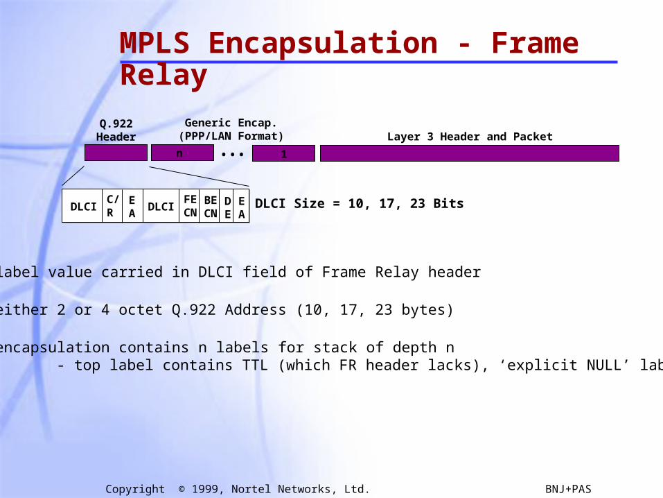
MPLS Encapsulation - Frame Relay
•••n 1
DLCIC/R
EA
DLCIFECN
BECN
DE
EA
Q.922Header
Generic Encap.(PPP/LAN Format) Layer 3 Header and Packet
DLCI Size = 10, 17, 23 Bits
• Current label value carried in DLCI field of Frame Relay header
• Can use either 2 or 4 octet Q.922 Address (10, 17, 23 bytes)
• Generic encapsulation contains n labels for stack of depth n - top label contains TTL (which FR header lacks), ‘explicit NULL’ label value
27
Copyright © 1999, Nortel Networks, Ltd. BNJ+PAS
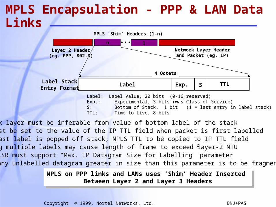
MPLS Encapsulation - PPP & LAN Data Links
Label Exp. S TTL
Label: Label Value, 20 bits (0-16 reserved)Exp.: Experimental, 3 bits (was Class of Service)S: Bottom of Stack, 1 bit (1 = last entry in label stack)TTL: Time to Live, 8 bits
Layer 2 Header(eg. PPP, 802.3)
•••Network Layer Header
and Packet (eg. IP)
4 Octets
MPLS ‘Shim’ Headers (1-n)
1n
• Network layer must be inferable from value of bottom label of the stack• TTL must be set to the value of the IP TTL field when packet is first labelled• When last label is popped off stack, MPLS TTL to be copied to IP TTL field• Pushing multiple labels may cause length of frame to exceed layer-2 MTU - LSR must support “Max. IP Datagram Size for Labelling” parameter - any unlabelled datagram greater in size than this parameter is to be fragmented
MPLS on PPP links and LANs uses ‘Shim’ Header Inserted Between Layer 2 and Layer 3 Headers
MPLS on PPP links and LANs uses ‘Shim’ Header Inserted Between Layer 2 and Layer 3 Headers
Label StackEntry Format
28
Copyright © 1999, Nortel Networks, Ltd. BNJ+PAS
Tutorial Outline
• Overview
• Label Encapsulations
• Label Distribution ProtocolsLabel Distribution Protocols
• MPLS & ATM
• IETF Status
• Nortel’s Activity
• Summary

29
Copyright © 1999, Nortel Networks, Ltd. BNJ+PAS
Label Distribution Protocols
• Overview of Hop-by-hop & Explicit
• Label Distribution Protocol (LDP)
• Constraint-based Routing LDP (CR-LDP)
• Extensions to RSVP
• Extensions to BGP
30
Copyright © 1999, Nortel Networks, Ltd. BNJ+PAS
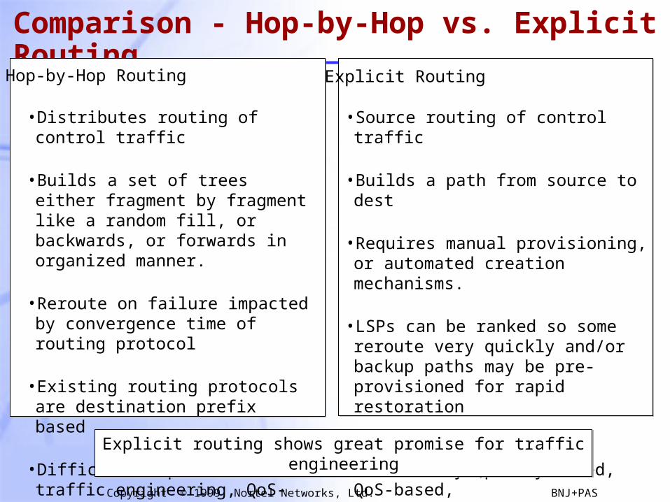
Comparison - Hop-by-Hop vs. Explicit Routing
Hop-by-Hop Routing Explicit Routing
• Source routing of control traffic
• Builds a path from source to dest
• Requires manual provisioning, or automated creation mechanisms.
• LSPs can be ranked so some reroute very quickly and/or backup paths may be pre-provisioned for rapid restoration
• Operator has routing flexibility (policy-based, QoS-based,
• Adapts well to traffic engineering
• Distributes routing of control traffic
• Builds a set of trees either fragment by fragment like a random fill, or backwards, or forwards in organized manner.
• Reroute on failure impacted by convergence time of routing protocol
• Existing routing protocols are destination prefix based
• Difficult to perform traffic engineering, QoS-based routing
Explicit routing shows great promise for traffic engineeringExplicit routing shows great promise for traffic engineering
31
Copyright © 1999, Nortel Networks, Ltd. BNJ+PAS
Explicit Routing - MPLS vs. Traditional Routing
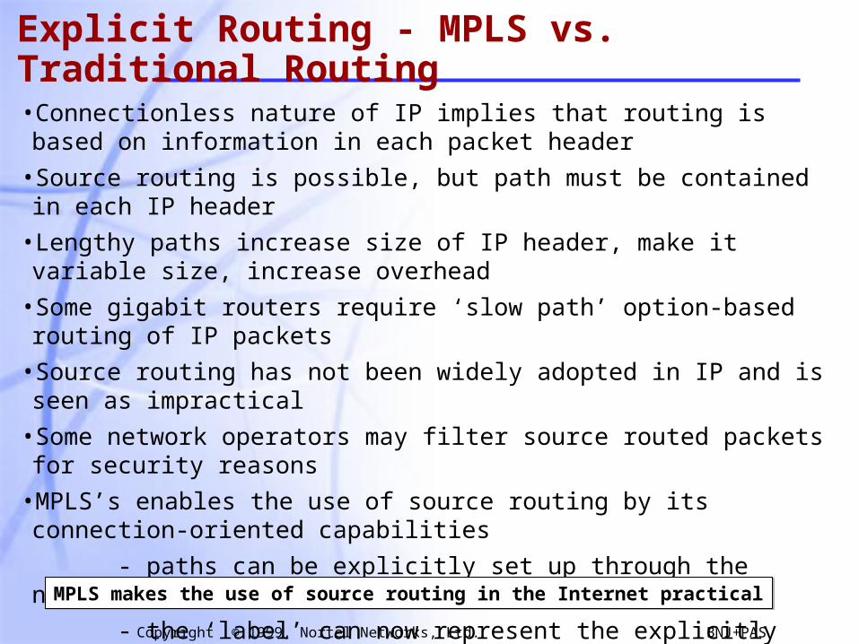
•Connectionless nature of IP implies that routing is based on information in each packet header
•Source routing is possible, but path must be contained in each IP header
•Lengthy paths increase size of IP header, make it variable size, increase overhead
•Some gigabit routers require ‘slow path’ option-based routing of IP packets
•Source routing has not been widely adopted in IP and is seen as impractical
•Some network operators may filter source routed packets for security reasons
•MPLS’s enables the use of source routing by its connection-oriented capabilities
- paths can be explicitly set up through the network
- the ‘label’ can now represent the explicitly routed path
•Loose and strict source routing can be supported
MPLS makes the use of source routing in the Internet practicalMPLS makes the use of source routing in the Internet practical
32
Copyright © 1999, Nortel Networks, Ltd. BNJ+PAS
Label Distribution Protocols
• Overview of Hop-by-hop & Explicit
• Label Distribution Protocol (LDP)
• Constraint-based Routing LDP (CR-LDP)
• Extensions to RSVP
• Extensions to BGP
33
Copyright © 1999, Nortel Networks, Ltd. BNJ+PAS
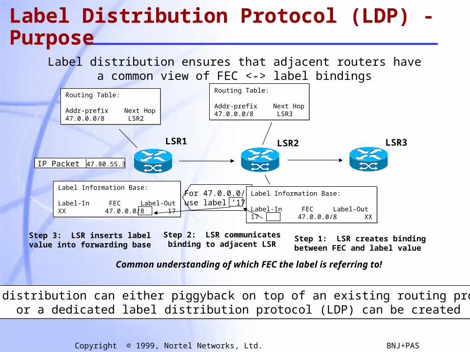
Label Distribution Protocol (LDP) - Purpose
Label distribution ensures that adjacent routers havea common view of FEC <-> label bindings
Routing Table:
Addr-prefix Next Hop47.0.0.0/8 LSR2
Routing Table:
Addr-prefix Next Hop47.0.0.0/8 LSR2
LSR1 LSR2 LSR3
IP Packet 47.80.55.3
Routing Table:
Addr-prefix Next Hop47.0.0.0/8 LSR3
Routing Table:
Addr-prefix Next Hop47.0.0.0/8 LSR3
For 47.0.0.0/8use label ‘17’
Label Information Base:
Label-In FEC Label-Out17 47.0.0.0/8 XX
Label Information Base:
Label-In FEC Label-Out17 47.0.0.0/8 XX
Label Information Base:
Label-In FEC Label-OutXX 47.0.0.0/8 17
Label Information Base:
Label-In FEC Label-OutXX 47.0.0.0/8 17
Step 1: LSR creates bindingbetween FEC and label value
Step 2: LSR communicatesbinding to adjacent LSR
Step 3: LSR inserts labelvalue into forwarding base
Common understanding of which FEC the label is referring to!
Label distribution can either piggyback on top of an existing routing protocol,or a dedicated label distribution protocol (LDP) can be created
Label distribution can either piggyback on top of an existing routing protocol,or a dedicated label distribution protocol (LDP) can be created
34
Copyright © 1999, Nortel Networks, Ltd. BNJ+PAS
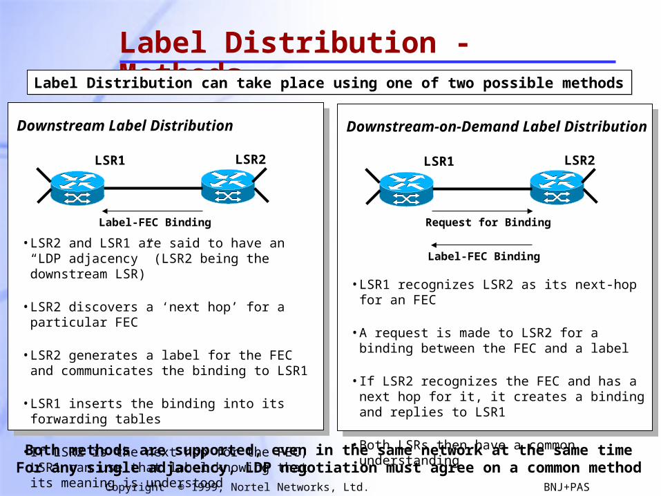
Label Distribution - Methods
LSR1 LSR2
Label Distribution can take place using one of two possible methodsLabel Distribution can take place using one of two possible methods
Downstream Label Distribution
Label-FEC Binding
• LSR2 and LSR1 are said to have an “LDP adjacency” (LSR2 being the downstream LSR)
• LSR2 discovers a ‘next hop’ for a particular FEC
• LSR2 generates a label for the FEC and communicates the binding to LSR1
• LSR1 inserts the binding into its forwarding tables
• If LSR2 is the next hop for the FEC, LSR1 can use that label knowing that its meaning is understood
LSR1 LSR2
Downstream-on-Demand Label Distribution
Label-FEC Binding
• LSR1 recognizes LSR2 as its next-hop for an FEC
• A request is made to LSR2 for a binding between the FEC and a label
• If LSR2 recognizes the FEC and has a next hop for it, it creates a binding and replies to LSR1
• Both LSRs then have a common understanding
Request for Binding
Both methods are supported, even in the same network at the same timeFor any single adjacency, LDP negotiation must agree on a common method
35
Copyright © 1999, Nortel Networks, Ltd. BNJ+PAS
#963
#14
#99
#311
#311
#311
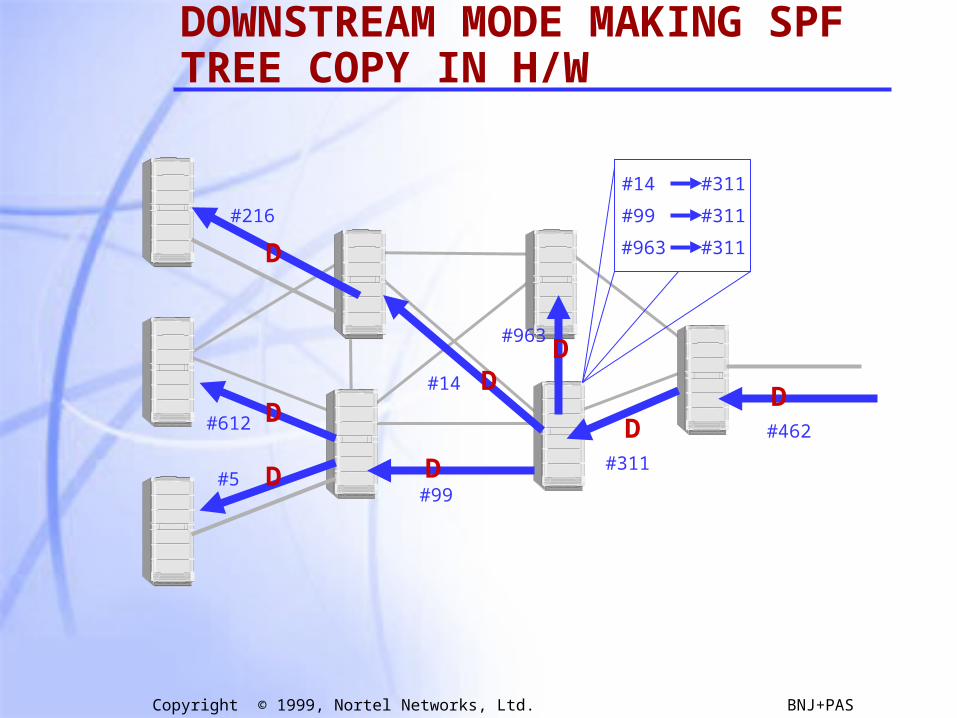
DOWNSTREAM MODE MAKING SPF TREE COPY IN H/W
#462
D
#311
D
#963D
#14 D
#99D
#216
D
#612 D
#5 D

36
Copyright © 1999, Nortel Networks, Ltd. BNJ+PAS
#963
#14
#99
#311
#311
#311
DOWNSTREAM ON DEMAND MAKING SPF TREE COPY IN H/W
#462
D
#311
D
#963D#14 D
#99D
#216
D
#612 D
#5 D
D?
D? D?D?
D?
D?
D?
D?
37
Copyright © 1999, Nortel Networks, Ltd. BNJ+PAS
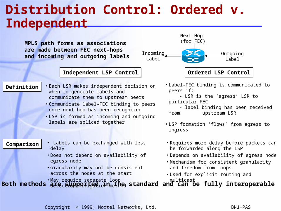
Distribution Control: Ordered v. Independent
Independent LSP ControlIndependent LSP Control Ordered LSP ControlOrdered LSP Control
Next Hop(for FEC)
OutgoingLabel
IncomingLabel
MPLS path forms as associationsare made between FEC next-hopsand incoming and outgoing labels
• Each LSR makes independent decision on when to generate labels and communicate them to upstream peers
• Communicate label-FEC binding to peers once next-hop has been recognized
• LSP is formed as incoming and outgoing labels are spliced together
• Label-FEC binding is communicated to peers if: - LSR is the ‘egress’ LSR to particular FEC - label binding has been received from
upstream LSR
• LSP formation ‘flows’ from egress to ingress
DefinitionDefinition
ComparisonComparison • Labels can be exchanged with less delay• Does not depend on availability of egress node• Granularity may not be consistent across the nodes
at the start• May require separate loop detection/mitigation
method
• Requires more delay before packets can be forwarded along the LSP
• Depends on availability of egress node• Mechanism for consistent granularity and freedom
from loops• Used for explicit routing and multicast
Both methods are supported in the standard and can be fully interoperable
38
Copyright © 1999, Nortel Networks, Ltd. BNJ+PAS
#963
#14
#99
#311
#311
#311
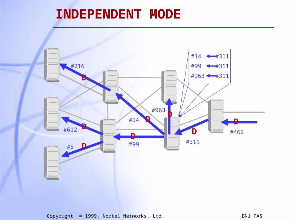
INDEPENDENT MODE
#462
D
#311
D
#963D
#14 D
#99D
#216
D
#612 D
#5 D
39
Copyright © 1999, Nortel Networks, Ltd. BNJ+PAS
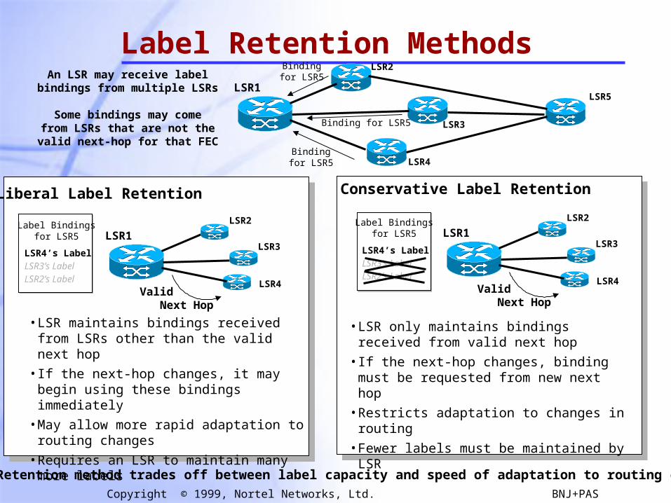
Label Retention MethodsLSR1
LSR2
LSR3
LSR4
LSR5
Bindingfor LSR5
Binding for LSR5
Bindingfor LSR5An LSR may receive label
bindings from multiple LSRs
Some bindings may comefrom LSRs that are not thevalid next-hop for that FEC
Liberal Label Retention Conservative Label Retention
LSR1
LSR2
LSR3
LSR4
Label Bindingsfor LSR5
Valid Next Hop
LSR4’s LabelLSR3’s LabelLSR2’s Label
LSR1
LSR2
LSR3
LSR4
Label Bindingsfor LSR5
Valid Next Hop
LSR4’s LabelLSR3’s LabelLSR2’s Label
• LSR maintains bindings received from LSRs other than the valid next hop
• If the next-hop changes, it may begin using these bindings immediately
• May allow more rapid adaptation to routing changes
• Requires an LSR to maintain many more labels
• LSR only maintains bindings received from valid next hop
• If the next-hop changes, binding must be requested from new next hop
• Restricts adaptation to changes in routing
• Fewer labels must be maintained by LSR
Label Retention method trades off between label capacity and speed of adaptation to routing changes
40
Copyright © 1999, Nortel Networks, Ltd. BNJ+PAS
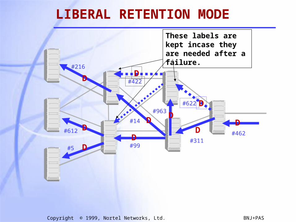
LIBERAL RETENTION MODE
#462
D
#311
D
#963D
#14 D
#99D
#216
D
#612 D
#5 D
#422D
#622 D
These labels are kept incase they are needed after a failure.
41
Copyright © 1999, Nortel Networks, Ltd. BNJ+PAS
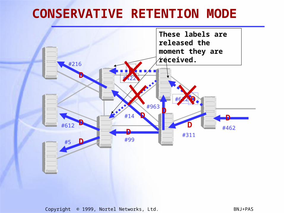
CONSERVATIVE RETENTION MODE
#462
D
#311
D
#963D
#14 D
#99D
#216
D
#612 D
#5 D
#422D
#622 D
These labels are released the moment they are received.
42
Copyright © 1999, Nortel Networks, Ltd. BNJ+PAS
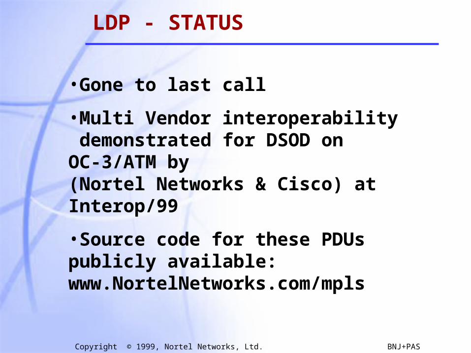
LDP - STATUS
•Gone to last call
•Multi Vendor interoperability demonstrated for DSOD on OC-3/ATM by (Nortel Networks & Cisco) at Interop/99
•Source code for these PDUs publicly available: www.NortelNetworks.com/mpls
43
Copyright © 1999, Nortel Networks, Ltd. BNJ+PAS
Label Distribution Protocols
• Overview of Hop-by-hop & Explicit
• Label Distribution Protocol (LDP)
• Constraint-based Routing LDP (CR-LDP)
• Extensions to RSVP
44
Copyright © 1999, Nortel Networks, Ltd. BNJ+PAS
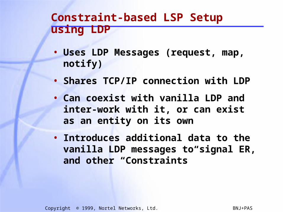
Constraint-based LSP Setup using LDP
• Uses LDP Messages (request, map, notify)
• Shares TCP/IP connection with LDP
• Can coexist with vanilla LDP and inter-work with it, or can exist as an entity on its own
• Introduces additional data to the vanilla LDP messages to signal ER, and other “Constraints”
45
Copyright © 1999, Nortel Networks, Ltd. BNJ+PAS
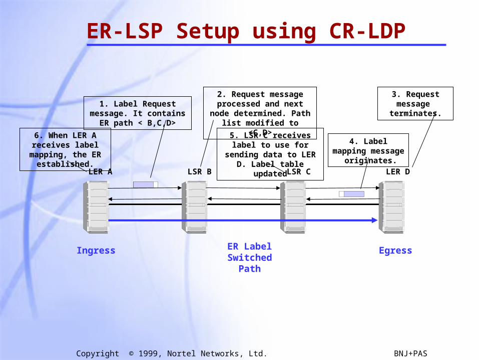
ER-LSP Setup using CR-LDP
LSR B LSR C LER DLER A
ER Label Switched Path
Ingress Egress
4. Label mapping message originates.
3. Request message terminates.
2. Request message processed and next node determined. Path list modified to <C,D>
1. Label Request message. It contains ER path < B,C,D>
5. LSR C receives label to use for sending data to LER
D. Label table updated
6. When LER A receives label mapping,
the ER established.
46
Copyright © 1999, Nortel Networks, Ltd. BNJ+PAS
#216
#14
#612
#5
#311
#462
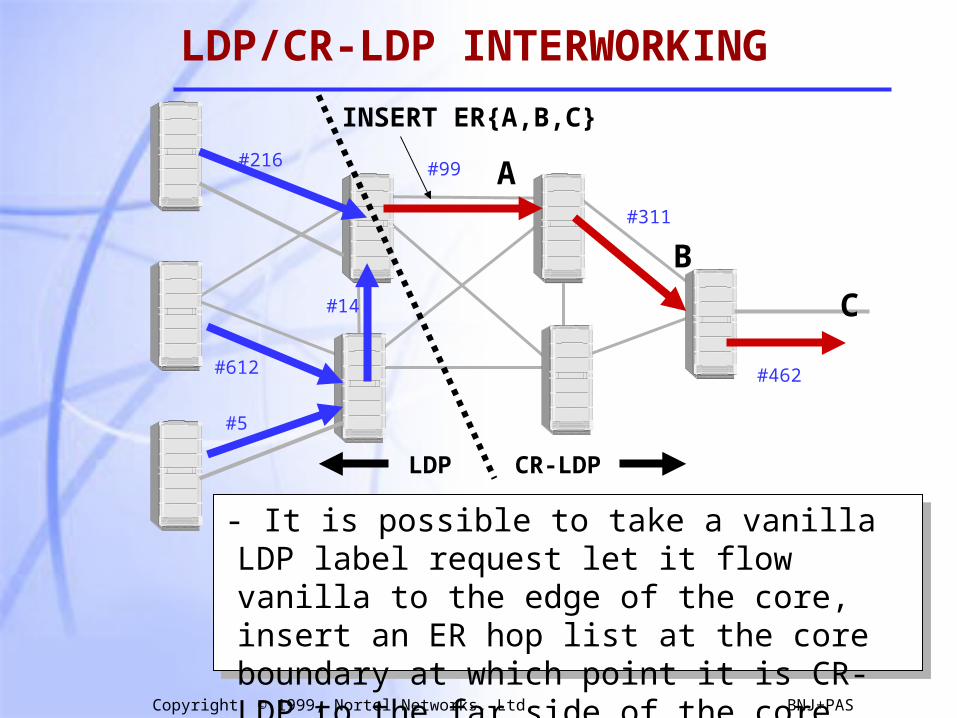
- It is possible to take a vanilla LDP label request let it flow vanilla to the edge of the core, insert an ER hop list at the core boundary at which point it is CR-LDP to the far side of the core.
A
B
C
LDP CR-LDP
#99
INSERT ER{A,B,C}
LDP/CR-LDP INTERWORKING
47
Copyright © 1999, Nortel Networks, Ltd. BNJ+PAS
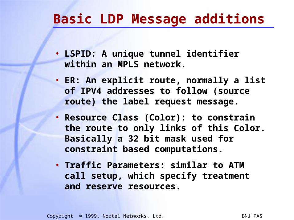
Basic LDP Message additions
• LSPID: A unique tunnel identifier within an MPLS network.
• ER: An explicit route, normally a list of IPV4 addresses to follow (source route) the label request message.
• Resource Class (Color): to constrain the route to only links of this Color. Basically a 32 bit mask used for constraint based computations.
• Traffic Parameters: similar to ATM call setup, which specify treatment and reserve resources.

48
Copyright © 1999, Nortel Networks, Ltd. BNJ+PAS
Length
Peak Data Rate (PDR)
Peak Burst Size (PBS)
Committed Data Rate (CDR)
Committed Burst Size (CBS)
Excess Burst Size (EBS)
Traf. Param. TLV U F
Reserved Weight Frequency Flags
Flags control “negotiability” of parameters
Frequency constrains the variable delay that may be introduced
Weight of the CRLSP in the “relative share”
Peak rate (PDR+PBS) maximum rate at which traffic should be sent to the CRLSP
Committed rate (CDR+CBS) the rate that the MPLS domain commits to be available to the CRLSP
Excess Burst Size (EBS) to measure the extent by which the traffic sent on a CRLSP exceeds the committed rate
32 bit fields are short IEEE floating point numbers
Any parameter may be used or not used by selecting appropriate values
CR-LDP Traffic Parameters
49
Copyright © 1999, Nortel Networks, Ltd. BNJ+PAS
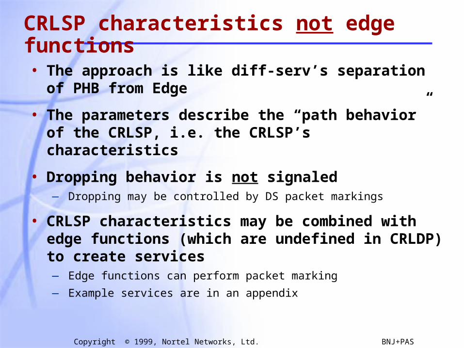
CRLSP characteristics not edge functions
• The approach is like diff-serv’s separation of PHB from Edge
• The parameters describe the “path behavior” of the CRLSP, i.e. the CRLSP’s characteristics
• Dropping behavior is not signaled— Dropping may be controlled by DS packet markings
• CRLSP characteristics may be combined with edge functions (which are undefined in CRLDP) to create services— Edge functions can perform packet marking
— Example services are in an appendix
50
Copyright © 1999, Nortel Networks, Ltd. BNJ+PAS
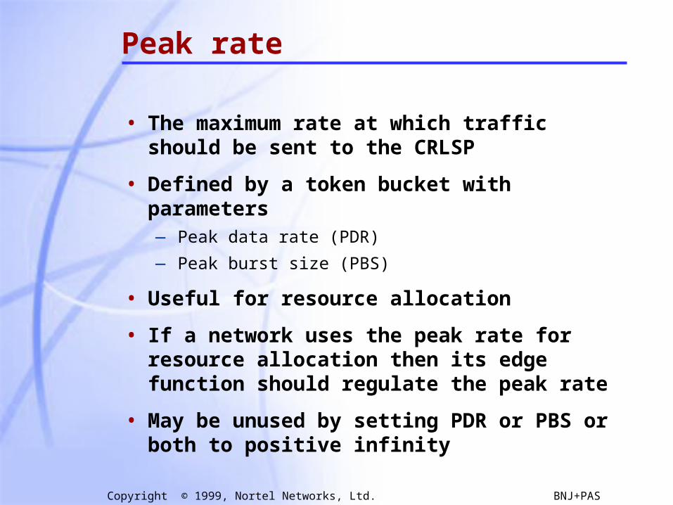
Peak rate
• The maximum rate at which traffic should be sent to the CRLSP
• Defined by a token bucket with parameters — Peak data rate (PDR)
— Peak burst size (PBS)
• Useful for resource allocation
• If a network uses the peak rate for resource allocation then its edge function should regulate the peak rate
• May be unused by setting PDR or PBS or both to positive infinity

51
Copyright © 1999, Nortel Networks, Ltd. BNJ+PAS
Committed rate
• The rate that the MPLS domain commits to be available to the CRLSP
• Defined by a token bucket with parameters — Committed data rate (CDR)
— Committed burst size (CBS)
• Committed rate is the bandwidth that should be reserved for the CRLSP
• CDR = 0 makes sense; CDR = + less so
• CBS describes the burstiness with which traffic may be sent to the CRLSP
52
Copyright © 1999, Nortel Networks, Ltd. BNJ+PAS
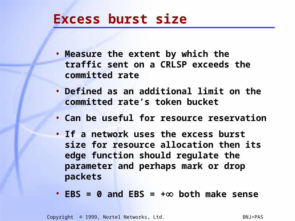
Excess burst size
• Measure the extent by which the traffic sent on a CRLSP exceeds the committed rate
• Defined as an additional limit on the committed rate’s token bucket
• Can be useful for resource reservation
• If a network uses the excess burst size for resource allocation then its edge function should regulate the parameter and perhaps mark or drop packets
• EBS = 0 and EBS = + both make sense
53
Copyright © 1999, Nortel Networks, Ltd. BNJ+PAS
Frequency
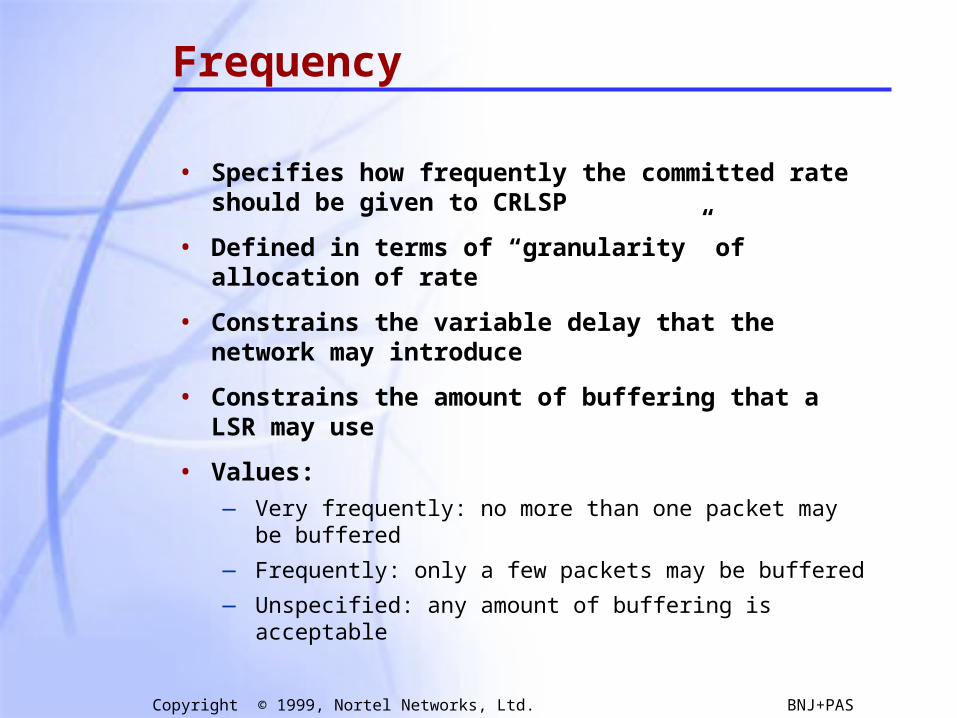
• Specifies how frequently the committed rate should be given to CRLSP
• Defined in terms of “granularity” of allocation of rate
• Constrains the variable delay that the network may introduce
• Constrains the amount of buffering that a LSR may use
• Values:— Very frequently: no more than one packet may be
buffered
— Frequently: only a few packets may be buffered
— Unspecified: any amount of buffering is acceptable

54
Copyright © 1999, Nortel Networks, Ltd. BNJ+PAS
Weight
• Specifies the CRLSP’s weight in the “realtive share algorithm”
• Implied but not stated:— CRLSPs with a larger weight get a bigger relative share
of the “excess bandwidth”
• Values:— 0 — the weight is not specified
— 1-255 — weights; larger numbers are larger weights
• The definition of “relative share” is network specific
55
Copyright © 1999, Nortel Networks, Ltd. BNJ+PAS
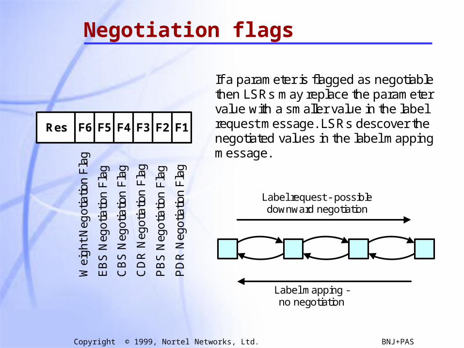
Negotiation flags
F1 F2 F3 F4 F5 F6 Res
PD
R N
egot
iatio
n F
lag
PB
S N
ego
tiatio
n F
lag
CD
R N
egot
iatio
n F
lag
CB
S N
egot
iatio
n F
lag
EB
S N
ego
tiatio
n F
lag
Wei
gh
t N
egot
iatio
n F
lag
If a parameter is flagged as negotiable then LSRs may replace the parameter value with a smaller value in the label request message. LSRs descover the negotiated values in the label mapping message.
Label request - possible downward negotiation
Label mapping - no negotiation

56
Copyright © 1999, Nortel Networks, Ltd. BNJ+PAS
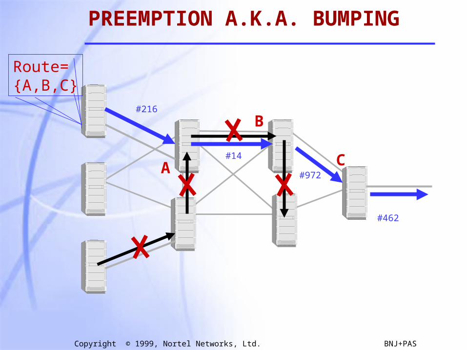
CR-LDP PREEMPTION
A CR-LSP carries an LSP priority. This priority can be used to allow new LSPs to bump existing LSPs of lower priority in order to steal their resources.
This is especially useful during times of failure and allows you to rank the LSPs such that the most important obtain resources before less important LSPs.
These are called the setupPriority and a holdingPriority and 8 levels are provided.

57
Copyright © 1999, Nortel Networks, Ltd. BNJ+PAS
CR-LDP PREEMPTION
When an LSP is established its setupPriority is compared with the holdingPriority of existing LSPs, any with lower holdingPriority may be bumped to obtain their resources.
This process may continue in a domino fashion until the lowest holdingPriority LSPs either clear or are on the worst routes.
58
Copyright © 1999, Nortel Networks, Ltd. BNJ+PAS
#216
#14
#462
#972A
B
C
Route={A,B,C}
PREEMPTION A.K.A. BUMPING
59
Copyright © 1999, Nortel Networks, Ltd. BNJ+PAS
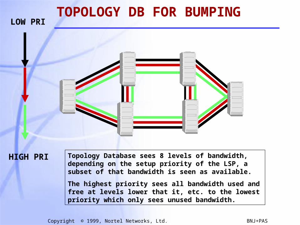
TOPOLOGY DB FOR BUMPINGLOW PRI
HIGH PRI Topology Database sees 8 levels of bandwidth, depending on the setup priority of the LSP, a subset of that bandwidth is seen as available.
The highest priority sees all bandwidth used and free at levels lower that it, etc. to the lowest priority which only sees unused bandwidth.
60
Copyright © 1999, Nortel Networks, Ltd. BNJ+PAS
CR-LDP Status
• Going through last call
• Demonstrated Interoperability Nov/98Nortel Networks, Ericson, GDC
• Extensions to CR-LDP now being proposed for:
• Bandwidth Adjustment (AT&T)Multicast ….
• Source code for these PDUs publicly available: www.NortelNetworks.com/mpls

61
Copyright © 1999, Nortel Networks, Ltd. BNJ+PAS
Label Distribution Protocols
• Overview of Hop-by-hop & Explicit
• Label Distribution Protocol (LDP)
• Constraint-based Routing LDP (CR-LDP)
• Extensions to RSVP
62
Copyright © 1999, Nortel Networks, Ltd. BNJ+PAS
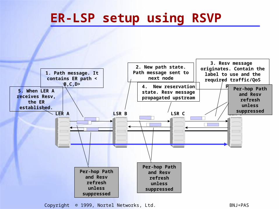
ER-LSP setup using RSVP
LSR B LSR C LER DLER A
1. Path message. It contains ER path < B,C,D>
2. New path state. Path message sent to next node
3. Resv message originates. Contain the label to use and the
required traffic/QoS para.
4. New reservation state. Resv message propagated
upstream
5. When LER A receives Resv, the ER
established.
Per-hop Path and Resv refresh unless
suppressed
Per-hop Path and Resv refresh unless
suppressed
Per-hop Path and Resv refresh unless
suppressed

63
Copyright © 1999, Nortel Networks, Ltd. BNJ+PAS
Tutorial Outline
• Overview
• Label Encapsulations
• Label Distribution Protocols
• MPLS & ATMMPLS & ATM• Constraint Based Routing with CR-LDP
• Summary
64
Copyright © 1999, Nortel Networks, Ltd. BNJ+PAS
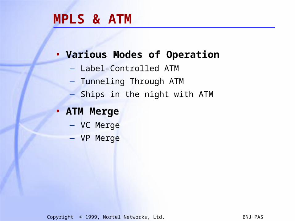
MPLS & ATM
• Various Modes of Operation— Label-Controlled ATM
— Tunneling Through ATM
— Ships in the night with ATM
• ATM Merge— VC Merge
— VP Merge
65
Copyright © 1999, Nortel Networks, Ltd. BNJ+PAS
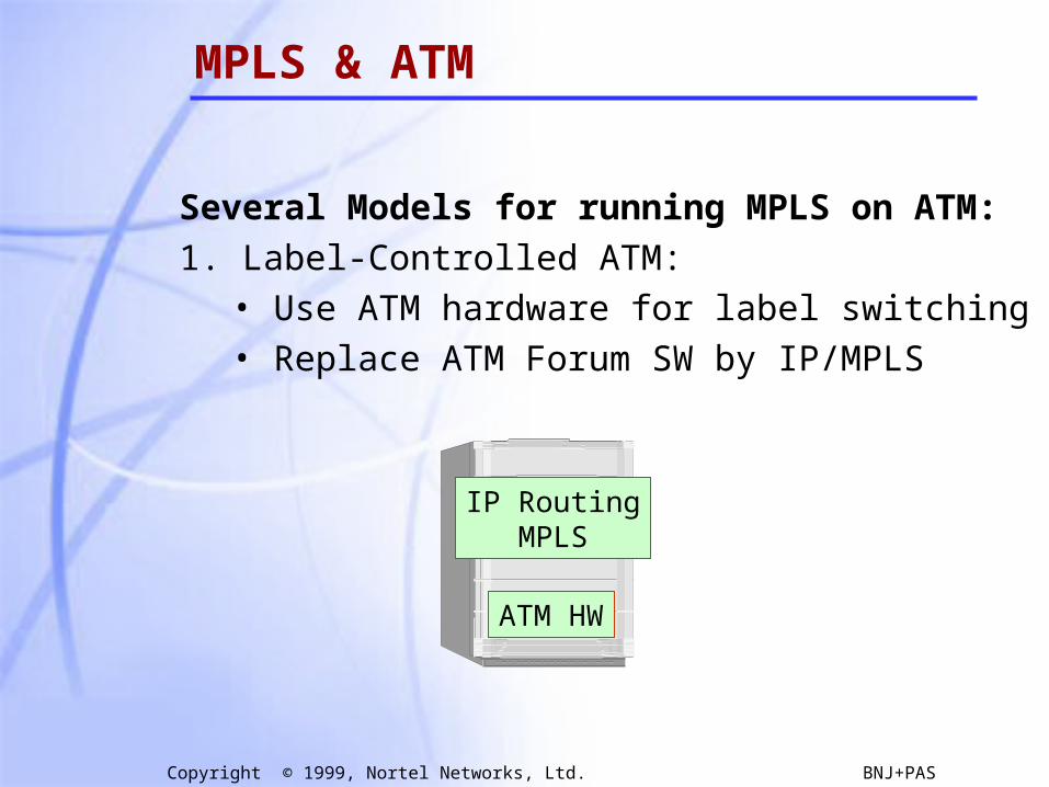
MPLS & ATM
Several Models for running MPLS on ATM:
1. Label-Controlled ATM:• Use ATM hardware for label switching• Replace ATM Forum SW by IP/MPLS
IP RoutingMPLS
ATM HW
66
Copyright © 1999, Nortel Networks, Ltd. BNJ+PAS
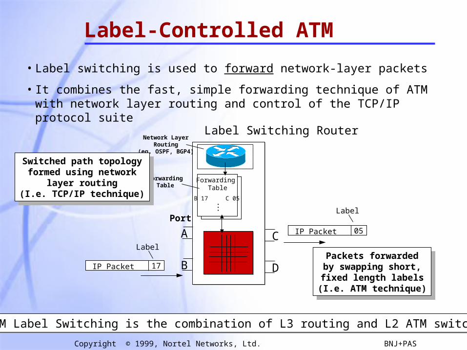
Label-Controlled ATM
• Label switching is used to forward network-layer packets
• It combines the fast, simple forwarding technique of ATM with network layer routing and control of the TCP/IP protocol suite
IP Packet 17
IP Packet 05
B
A
D
C
Forwarding Table
B 17 C 05•••
Port
Label Switching Router
ForwardingTable
Network LayerRouting
(eg. OSPF, BGP4)
Label
Packets forwardedby swapping short,fixed length labels
(I.e. ATM technique)
Packets forwardedby swapping short,fixed length labels
(I.e. ATM technique)
Switched path topologyformed using network
layer routing(I.e. TCP/IP technique)
Switched path topologyformed using network
layer routing(I.e. TCP/IP technique)
Label
ATM Label Switching is the combination of L3 routing and L2 ATM switchingATM Label Switching is the combination of L3 routing and L2 ATM switching

67
Copyright © 1999, Nortel Networks, Ltd. BNJ+PAS
2. MPLS Over ATM
MPLSATM Network
MPLS
LSR
LSR
VCVP
Two Models
Internet Draft:VCID notification over ATM Link

68
Copyright © 1999, Nortel Networks, Ltd. BNJ+PAS
3. Ships in the Night
• ATM Forum and MPLS control planes both run on the same hardware but are isolated from each other, i.e. they do not interact.
• This allows a single device to simultaneously operate as both an MPLS LSR and an ATM switch.
• Important for migrating MPLS into an ATM network
ATMSW
LSR ATM
MPLS
ATMSW
LSR
69
Copyright © 1999, Nortel Networks, Ltd. BNJ+PAS
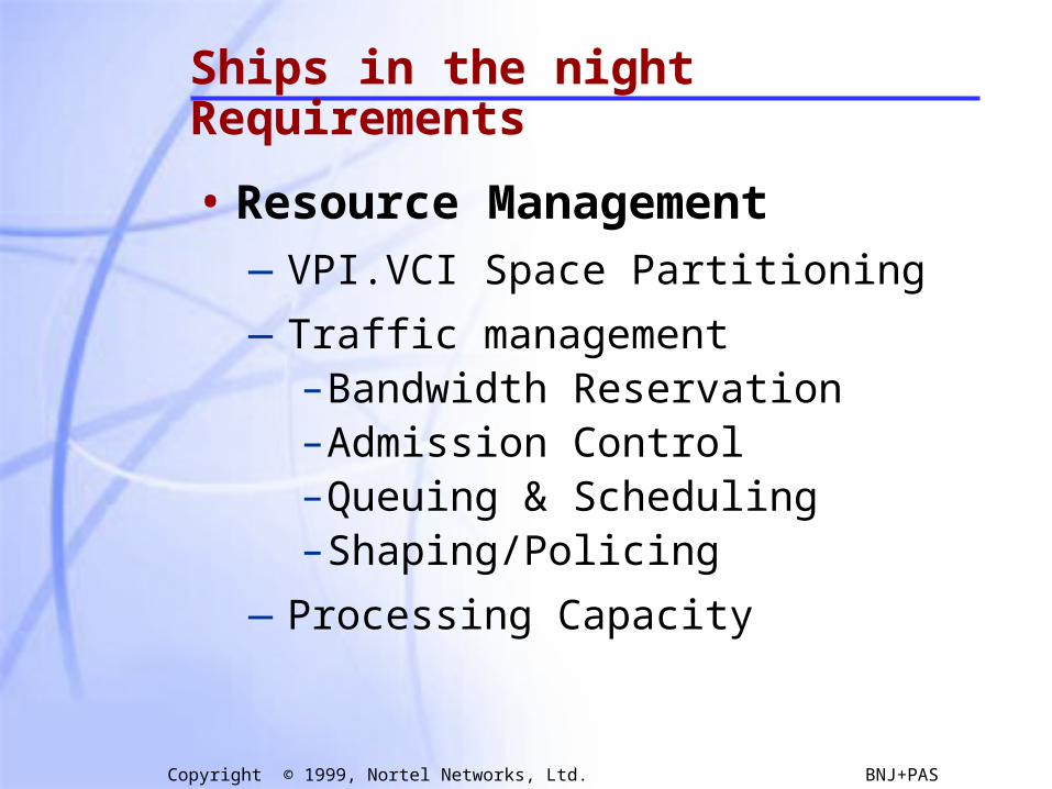
Ships in the night Requirements
• Resource Management—VPI.VCI Space Partitioning
—Traffic management–Bandwidth Reservation –Admission Control–Queuing & Scheduling–Shaping/Policing
—Processing Capacity
70
Copyright © 1999, Nortel Networks, Ltd. BNJ+PAS
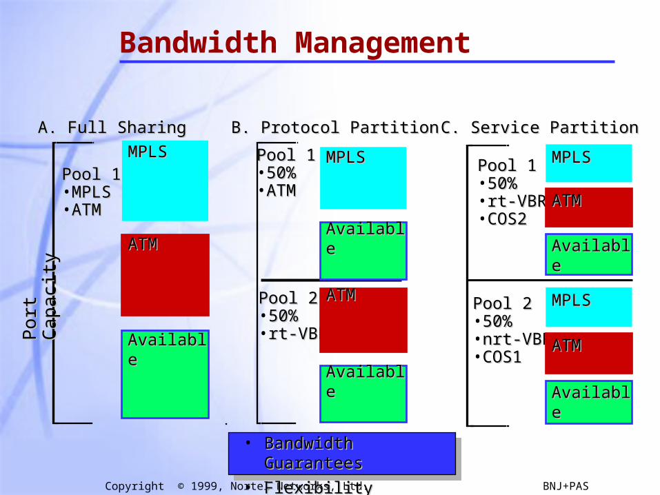
Bandwidth Management
• Bandwidth GuaranteesBandwidth Guarantees
• FlexibilityFlexibility
A.A. Full SharingFull Sharing
Po
rt C
ap
acity
Po
rt C
ap
acity
Pool 1 Pool 1 •MPLSMPLS•ATMATM
MPLSMPLS
ATMATM
AvailableAvailable
B. Protocol PartitionB. Protocol Partition
Pool 2 Pool 2 •50%50%•rt-VBRrt-VBR
Pool 1 Pool 1 •50%50%•ATMATM
MPLSMPLS
ATMATM
AvailableAvailable
AvailableAvailable
C. Service PartitionC. Service Partition
Pool 2 Pool 2 •50%50%•nrt-VBRnrt-VBR•COS1COS1
Pool 1 Pool 1 •50%50%•rt-VBRrt-VBR•COS2COS2
MPLSMPLS
ATMATM
AvailableAvailable
MPLSMPLS
ATMATM
AvailableAvailable
71
Copyright © 1999, Nortel Networks, Ltd. BNJ+PAS
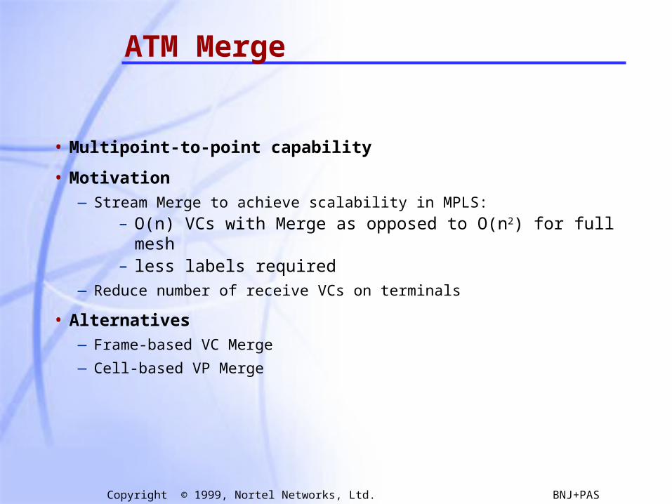
ATM Merge
• Multipoint-to-point capability
• Motivation—Stream Merge to achieve scalability in MPLS:
– O(n) VCs with Merge as opposed to O(n2) for full mesh– less labels required
—Reduce number of receive VCs on terminals
• Alternatives—Frame-based VC Merge
—Cell-based VP Merge
72
Copyright © 1999, Nortel Networks, Ltd. BNJ+PAS
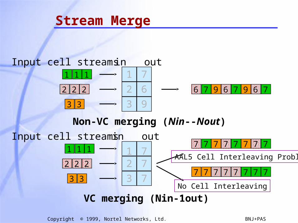
Stream Merge
111
2 2 2
3 3
111
2 2 2
3 3
Input cell streams
Input cell streams
in out1
2
3
7
6
9
12
3
77
7
in out
Non-VC merging (Nin--Nout)
VC merging (Nin-1out)
7 7 7 7 7 777
6 7 9 6 7 79 6
7 7 7 7 7 77
No Cell Interleaving
7
AAL5 Cell Interleaving Problem
73
Copyright © 1999, Nortel Networks, Ltd. BNJ+PAS
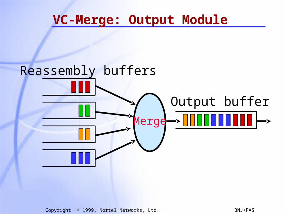
VC-Merge: Output Module
Merge
Reassembly buffers
Output buffer
74
Copyright © 1999, Nortel Networks, Ltd. BNJ+PAS
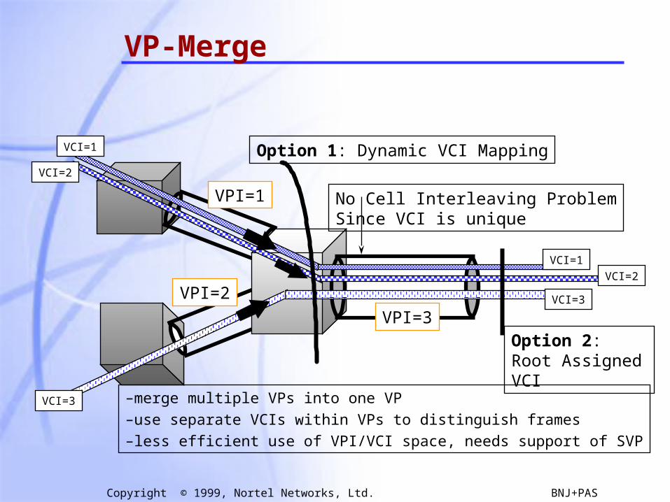
VP-Merge
VPI=3
VPI=2
VCI=1
VPI=1
VCI=2
VCI=3
VCI=1
VCI=2
VCI=3
–merge multiple VPs into one VP
–use separate VCIs within VPs to distinguish frames
–less efficient use of VPI/VCI space, needs support of SVP
No Cell Interleaving ProblemSince VCI is unique
Option 1: Dynamic VCI Mapping
Option 2: Root Assigned VCI
75
Copyright © 1999, Nortel Networks, Ltd. BNJ+PAS
Tutorial Outline
• Overview
• Label Encapsulations
• Label Distribution Protocols
• MPLS & ATM
• Constraint Based Routing with CR-LDP
• SummarySummary
76
Copyright © 1999, Nortel Networks, Ltd. BNJ+PAS
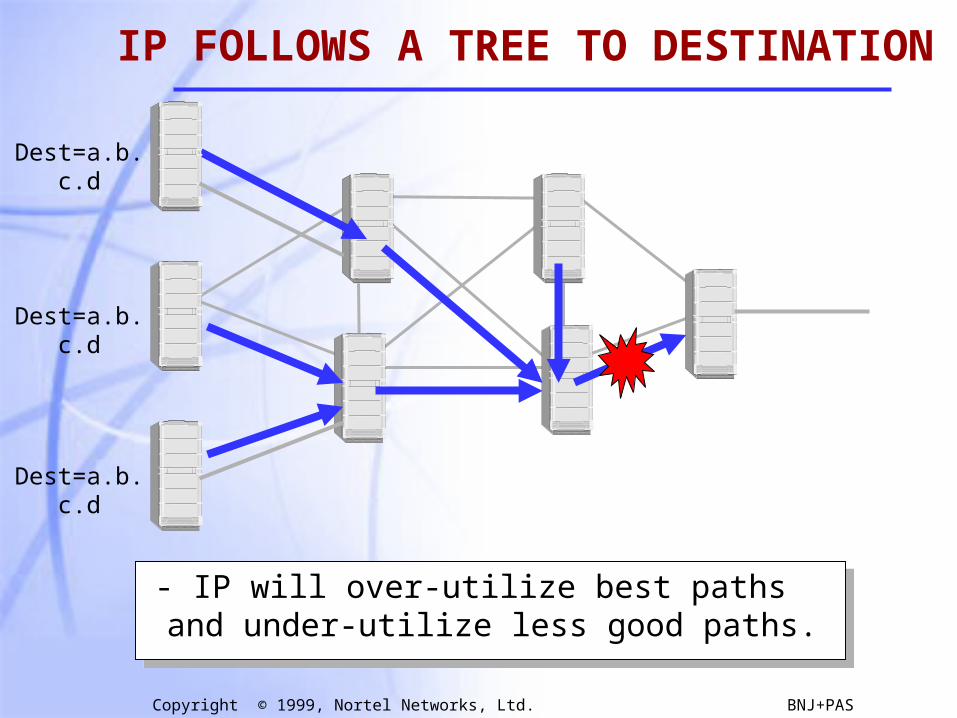
- IP will over-utilize best paths and under-utilize less good paths.
Dest=a.b.c.d
Dest=a.b.c.d
Dest=a.b.c.d
IP FOLLOWS A TREE TO DESTINATION

77
Copyright © 1999, Nortel Networks, Ltd. BNJ+PAS
#216
#14
#612
#5 #99 #311
#963
#462
- Ultra fast, simple forwarding a.k.a switching
- Follows same route as normal IP datapath
- So like IP, LDP will over-utilize best paths and under-utilize less good paths.
HOP-BY-HOP(A.K.A Vanilla) LDP
78
Copyright © 1999, Nortel Networks, Ltd. BNJ+PAS
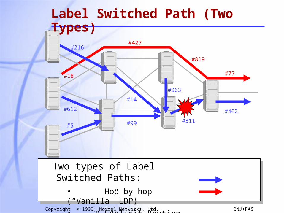
Two types of Label Switched Paths:• Hop by hop (“Vanilla” LDP)
• Explicit Routing (LDP+”ER”)
#18
#427
#819
#216
#14
#612
#5 #99 #311
#963
#462
#77
Label Switched Path (Two Types)
79
Copyright © 1999, Nortel Networks, Ltd. BNJ+PAS
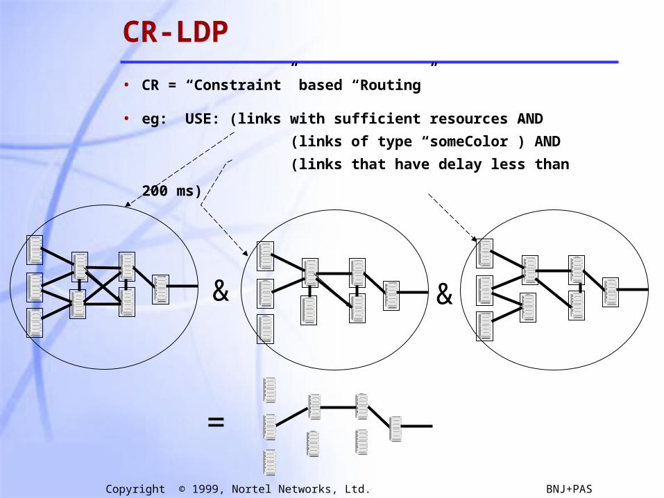
• CR = “Constraint” based “Routing”
• eg: USE: (links with sufficient resources AND
(links of type “someColor”) AND
(links that have delay less than 200 ms)
&&
=
CR-LDP
80
Copyright © 1999, Nortel Networks, Ltd. BNJ+PAS
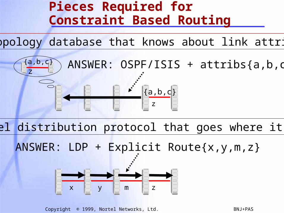
1) A topology database that knows about link attributes.
2) A label distribution protocol that goes where it’s told.
z
{a,b,c}
ANSWER: OSPF/ISIS + attribs{a,b,c}
zmyx
ANSWER: LDP + Explicit Route{x,y,m,z}
z{a,b,c}
Pieces Required for Constraint Based Routing
81
Copyright © 1999, Nortel Networks, Ltd. BNJ+PAS
• Overview
• Label Encapsulations
• Label Distribution Protocols
• MPLS & ATM
• Constraint Based Routing with CR-LDP
• SummarySummary
Tutorial Outline

82
Copyright © 1999, Nortel Networks, Ltd. BNJ+PAS
Summary of Motivations for MPLS• Simplified forwarding based on exact match of fixed length label
- initial drive for MPLS was based on existance of cheap, fast ATM switches• Separation of routing and forwarding in IP networks
- facilitates evolution of routing techniques by fixing the forwarding method- new routing functionality can be deployed without changing the forwarding
techniques of every router in the Internet• Facilitates the integration of ATM and IP
- allows carriers to leverage their large investment of ATM equipment- eliminates the adjacency problem of VC-mesh over ATM
•Enables the use of explicit routing/source routing in IP networks- can be easily used for such things as traffic management, QoS routing
•Promotes the partitioning of functionality within the network- move granular processing of packets to edge; restrict core to packet forwarding- assists in maintaining scalability of IP protocols in large networks
•Improved routing scalability through stacking of labels- removes the need for full routing tables from interior routers in transit domain;
only routes to border routers are required•Applicability to both cell and packet link-layers
- can be deployed on both cell (eg. ATM) and packet (eg. FR, Ethernet) media- common management and techniques simplifies engineering
Many drivers exist for MPLS above and beyond high speed forwarding Many drivers exist for MPLS above and beyond high speed forwarding
83
Copyright © 1999, Nortel Networks, Ltd. BNJ+PAS
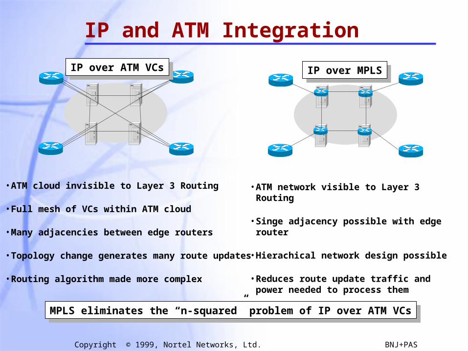
IP and ATM Integration
IP over ATM VCsIP over ATM VCs
• ATM cloud invisible to Layer 3 Routing
• Full mesh of VCs within ATM cloud
• Many adjacencies between edge routers
• Topology change generates many route updates
• Routing algorithm made more complex
• ATM network visible to Layer 3 Routing
• Singe adjacency possible with edge router
• Hierachical network design possible
• Reduces route update traffic and power needed to process them
IP over MPLSIP over MPLS
MPLS eliminates the “n-squared” problem of IP over ATM VCsMPLS eliminates the “n-squared” problem of IP over ATM VCs
84
Copyright © 1999, Nortel Networks, Ltd. BNJ+PAS
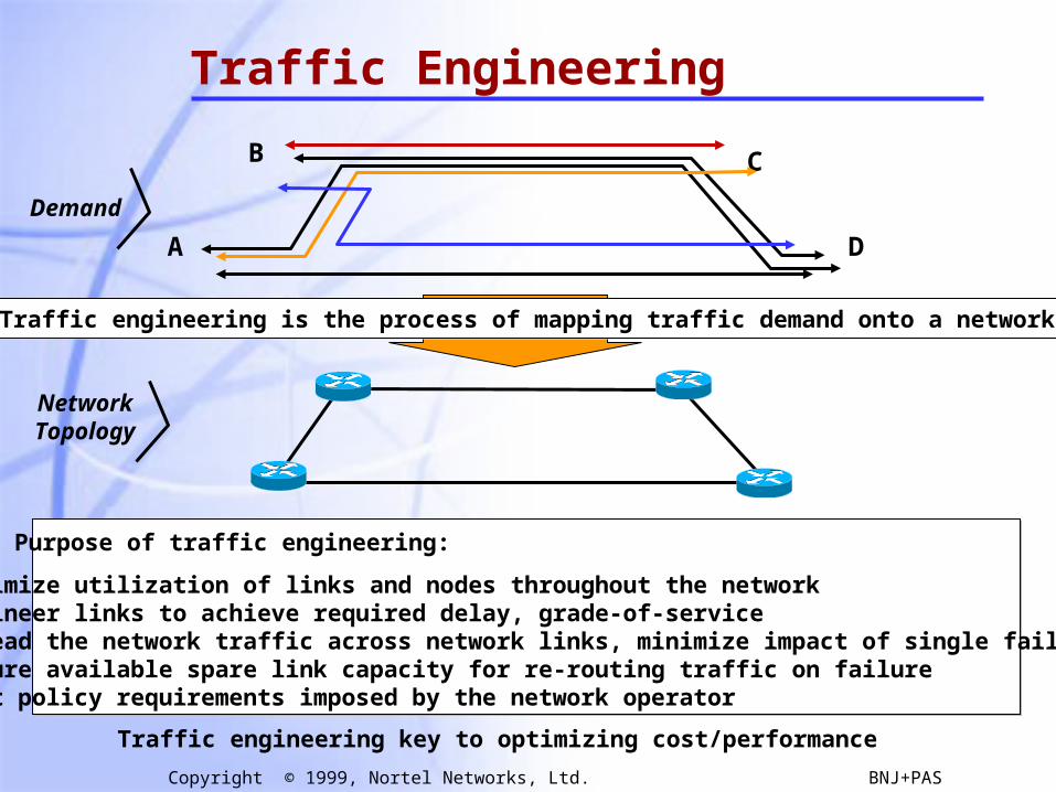
Traffic Engineering
A
B C
D
Traffic engineering is the process of mapping traffic demand onto a networkTraffic engineering is the process of mapping traffic demand onto a network
Demand
NetworkTopology
Purpose of traffic engineering:
• Maximize utilization of links and nodes throughout the network• Engineer links to achieve required delay, grade-of-service• Spread the network traffic across network links, minimize impact of single failure• Ensure available spare link capacity for re-routing traffic on failure• Meet policy requirements imposed by the network operator
Traffic engineering key to optimizing cost/performance

85
Copyright © 1999, Nortel Networks, Ltd. BNJ+PAS
Traffic Engineering AlternativesCurrent methods of traffic engineering:
Manipulating routing metrics
Use PVCs over an ATM backbone
Over-provision bandwidth
Difficult to manage
Not scalable
Not economical
MPLS combines benefits of ATM and IP-layer traffic engineering
Chosen by routing protocol(least cost)
Chosen by Traffic Eng.(least congestion)
Example Network:
MPLS provides a new method to do traffic engineering (traffic steering)
Ingress nodeexplicitly routes
traffic over uncongested path
Potential benefits of MPLS for traffic engineering: - allows explicitly routed paths - no “n-squared” problem - per FEC traffic monitoring - backup paths may be configured
operator controlscalable granularity of feedback redundancy/restoration
Congested Node
86
Copyright © 1999, Nortel Networks, Ltd. BNJ+PAS
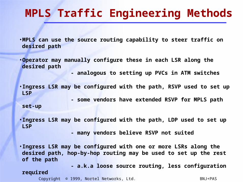
MPLS Traffic Engineering Methods
• MPLS can use the source routing capability to steer traffic on desired path
• Operator may manually configure these in each LSR along the desired path - analogous to setting up PVCs in ATM switches
• Ingress LSR may be configured with the path, RSVP used to set up LSP - some vendors have extended RSVP for MPLS path set-up
• Ingress LSR may be configured with the path, LDP used to set up LSP - many vendors believe RSVP not suited
• Ingress LSR may be configured with one or more LSRs along the desired path, hop-by-hop routing may be used to set up the rest of the path
- a.k.a loose source routing, less configuration required
• If desired for control, route discovered by hop-by-hop routing can be frozen - a.k.a “route pinning”
• In the future, constraint-based routing will offload traffic engineering tasks from the operator to the network itself
87
Copyright © 1999, Nortel Networks, Ltd. BNJ+PAS
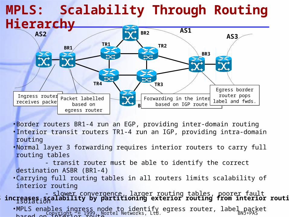
MPLS: Scalability Through Routing Hierarchy
BR1
BR2
BR3
BR4
TR1 TR2
TR3TR4
AS1AS2 AS3
• Border routers BR1-4 run an EGP, providing inter-domain routing• Interior transit routers TR1-4 run an IGP, providing intra-domain routing• Normal layer 3 forwarding requires interior routers to carry full routing tables - transit router must be able to identify the correct destination ASBR (BR1-4)• Carrying full routing tables in all routers limits scalability of interior routing - slower convergence, larger routing tables, poorer fault isolation• MPLS enables ingress node to identify egress router, label packet based on interior route• Interior LSRs would only require enough information to forward packet to egress
Ingress routerreceives packetIngress router
receives packetPacket labelled
based onegress router
Packet labelled based on
egress router
Forwarding in the interiorbased on IGP route
Forwarding in the interiorbased on IGP route
Egress borderrouter pops
label and fwds.
Egress borderrouter pops
label and fwds.
MPLS increases scalability by partitioning exterior routing from interior routing

88
Copyright © 1999, Nortel Networks, Ltd. BNJ+PAS
MPLS: Partitioning Routing and Forwarding
Routing
Forwarding
OSPF, IS-IS, BGP, RIP
MPLS
Forwarding Table
Based on:Classful Addr. Prefix?Classless Addr. Prefix?Multicast Addr.?Port No.?ToS Field?
Based on:Exact Match on Fixed Length Label
• Current network has multiple forwarding paradigms - class-ful longest prefix match (Class A,B,C boundaries) - classless longest prefix match (variable boundaries) - multicast (exact match on source and destination) - type-of-service (longest prefix. match on addr. + exact match on ToS)• As new routing methods change, new route look-up algorithms are required - introduction of CIDR• Next generation routers will be based on hardware for route look-up - changes will require new hardware with new algorithm• MPLS has a consistent algorithm for all types of forwarding; partitions routing/fwding - minimizes impact of the introduction of new forwarding methods
MPLS introduces flexibility through consistent forwarding paradigmMPLS introduces flexibility through consistent forwarding paradigm
89
Copyright © 1999, Nortel Networks, Ltd. BNJ+PAS
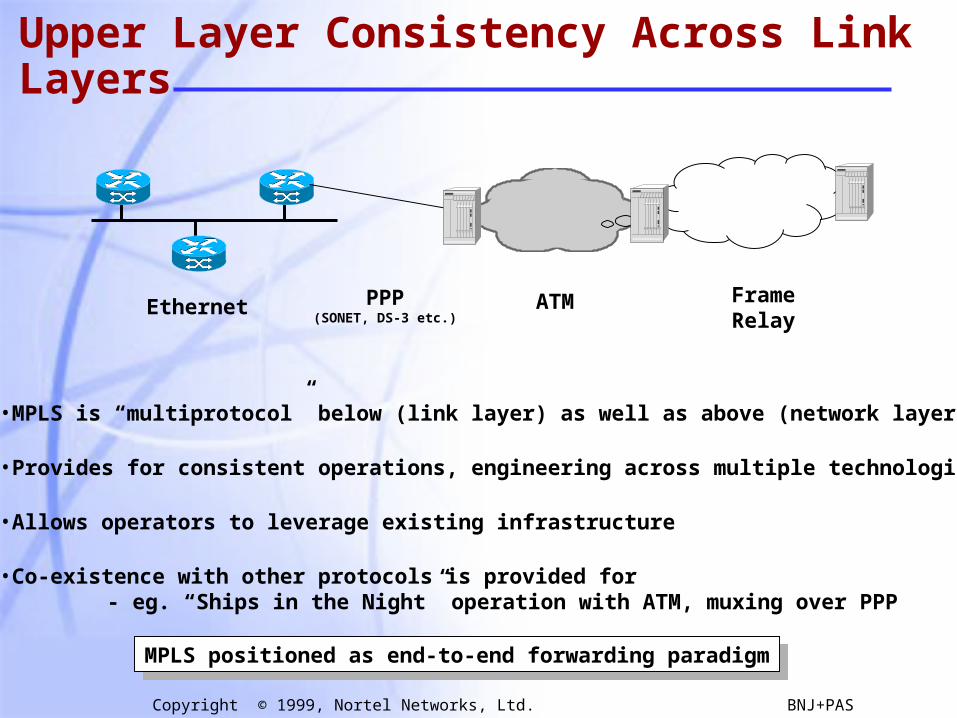
Upper Layer Consistency Across Link Layers
Ethernet PPP(SONET, DS-3 etc.)
ATM FrameRelay
• MPLS is “multiprotocol” below (link layer) as well as above (network layer)
• Provides for consistent operations, engineering across multiple technologies
• Allows operators to leverage existing infrastructure
• Co-existence with other protocols is provided for - eg. “Ships in the Night” operation with ATM, muxing over PPP
MPLS positioned as end-to-end forwarding paradigmMPLS positioned as end-to-end forwarding paradigm

90
Copyright © 1999, Nortel Networks, Ltd. BNJ+PAS
Summary
• MPLS is an exciting promising emerging technology
• Basic functionality (Encapsulation and basic Label Distribution) has been defined by the IETF
• Traffic engineering based on MPLS/IP is just round the corner.
• Convergence is one step closer …...