msc software technology for...
TRANSCRIPT

MSC.Software Technology For Shipbuilders
Domenico Cacozza
Fabio Scannavino

MSC.Software Technology
MSC.Software provides the shipbuilding industry with virtual prototyping
solutions that ensure safety and reliability, compliance with requirements, and
make the ship design and verification process faster and more efficient.
Innovation and Risk Management

Application AreasMSC.Software solutions for the shipbuilding industry include:
• Modeling
• Static Linear Analysis
• Nonlinear Analysis
• Shaft & hull vibration
• Modal and Dynamic Analysis
• Strength & hull integrity
• Buckling analysis
• Fire loading
• Ship modeling automation
• Wave loading
• Underwater shock analysis
• Sloshing & ship dynamics
• Slamming
• Fatigue life prediction
• Acoustics & noise propagation
• Collision
• Optimization
• Electromagnetic
• Motion
• Rotor dynamics
• System & Controls
• On-board equipment modeling & analysis
• ……..

Static Linear Analysis

The template helps the users in the correct creation of the
model and in the generation of the documentation for the
certification.
Every section of the ship should be verified in hogging and sagging
condition
8 different load conditions:
caseAP
caseAM
caseBP
caseBM
caseCP
caseCM
caseDP
caseDM
Report with these results
- Displacements
- Equivalent Von Mises
- Component XX of stress
- Component YY of stress
- Component XY of stress
(8 load x 5 results) *2 view = 80 pictures
8 tables with key results
Ship modeling automation

Nonlinear Analysis

Manufacturing Process
7

Welding Analysis

Thermo-Mechanical Analysis

Composites Structures in Marine

● America’s Cup Yacht
● Overall weight 25t
● Ballast weight 20t (80%)
● Mast mass 330kg
● Boom mass 60kg
● Hull/deck mass 1700kg (of which 70% constrained by rule)
● Fin mass 1000kg (steel! Best modulus per unit volume)
● High performance
● Variable loading
● Benefits:
● Ply based model
● Automated generation
● Failure analysis
● Manufacturing link
● Optimization
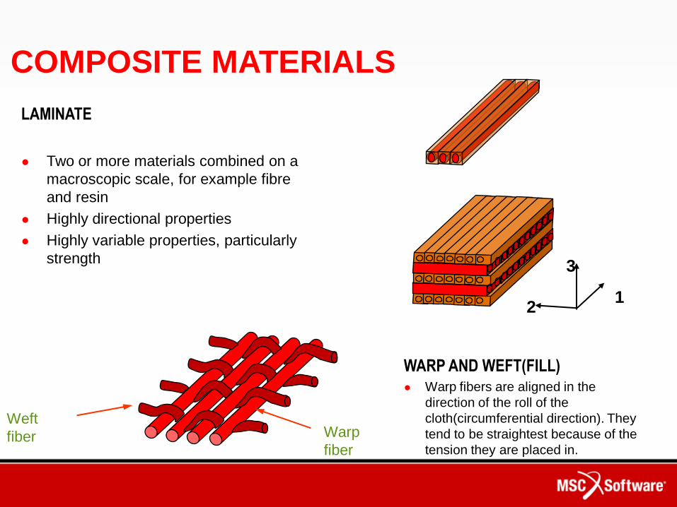
COMPOSITE MATERIALS
LAMINATE
● Two or more materials combined on a
macroscopic scale, for example fibre
and resin
● Highly directional properties
● Highly variable properties, particularly
strength
2
3
1
WARP AND WEFT(FILL)● Warp fibers are aligned in the
direction of the roll of the
cloth(circumferential direction). They
tend to be straightest because of the
tension they are placed in.
Warp
fiber
Weft
fiber

• The real fibre direction could change up to 75 degrees
• A undevelopable surface (Double Curvature) is droppable because the fold can be cut
Draping Simulation

• Laminate effective material properties
are tailored to meet performance
requirements through the use of
lamination theory integrated in the
MSC.Software products.
Classical Lamination Theory (CLT)
= 0º, t=0.0125
= 45º, t=0.01
= 90º, t=0.01
= -45º, t=0.01
=0º, t=0.01
= -45º, t=0.0125
= 90º, t=0.0125
= 45º, t=0.0125
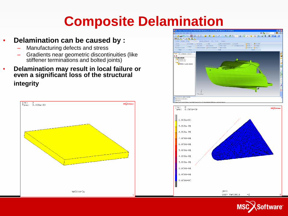
Composite Delamination
• Delamination can be caused by :– Manufacturing defects and stress
– Gradients near geometric discontinuities (like stiffener terminations and bolted joints)
• Delamination may result in local failure or even a significant loss of the structural
integrity

Composite Fracture Mechanics

Cohesive simulation

Sensitivity Analysisand Optimization
Geometry & FEA Results
Loading and Test (Lab) Results
Materials InformationDamage Distributions
Analysis Options
• Stress (total) Life
• Strain (initiation) Life
• Crack Propagation
• Vibration Fatigue
• Spot Weld Analyzer
• Software Strain Gauge
• Utilities
• Pre & Post
• Multi-axial Fatigue
Fatigue Life Contours
1500
-1500120
Strain (uE)
Time (seconds)
DISPLAY OF SIGNAL: TEST101.DAC
Strain Life
Plot605M30Sf': 857 b: -0.067 Ef': 0.636 c: -0.579
1E-3
1E-2
1E-1
Strain Amplitude
(M/M)
1E0 1E1 1E2 1E3 1E4 1E5 1E6 1E7 1E8
Life (Reversals)
1E3 1E4 1E5 1E61
2
3
4
5
6
7
Cross Plot of Data :
S61STRAIN1KT
Life(Miles)
Kt( )
0
1574.7 -750.4
808.70
4.8548
RangeuE
X-Axis
MeanuEY-Axis
DamageZ-Axis
DAMAGE HISTOGRAM DISTRIBUTION FOR : TRACK05.DHHMaximum height : 4.8548 Z Units : %
Fatigue Analysis

Multi Body Dynamics

Multi Body Dynamics


Dynamical Impact Analysis
Case Study: A study on Evaluation of Collision Strength for FPSO
The analysis of ship collision has attracted attention in order to
prevent a environment pollution.
Some of the ship collision accidents in the past remain instructive
records in losses of human lives and properties and
environmental damages.
The research activities of the ship collision have attended to
large oil carrier, LNG carrier, FPSO and so on that may cause
serious environmental pollution and in recent, some ship owners
have requested the collision evaluation for design.

Dynamical Shock Load Analysis
Response of Ships to Underwater Explosions
The response of structural panels subjected to
non-contact explosion is of vital importance in
the design of air crafts, marine vehicles such as
ships, submarines and steel off-shore towers.

Computational Fluid Dynamics

Helsinki-based WB-Sails
Helsinki-based WB-Sails was founded 30 years ago to manufacture sails for the
Olympic classes and small racing boats. During the past twenty years WB-Sails has
turned from a small backyard loft into a respectable sail maker. They have been
pioneering sail making CAD/CAM in the world and have been using CAE since 1979.

Fluid-Structure Interaction
Ship motion can often violent fluid motions in a partially filled tank and it may cause very high pressures which last for very short duration. These pressure may cause considerable damage to tank structure.
SLOSHING

Fluid-Structure Interaction
Case Study: HHIRoll motion
Pitch motion
Heavy Industry/Shipbuilding
Even though the sloshing pressures and flow velocities have been investigated forthe filling height 10% and 95%, the significant sloshing behavior has not been checked.
High pressure and velocity has occurred in tank roll excitation rather than pitch.
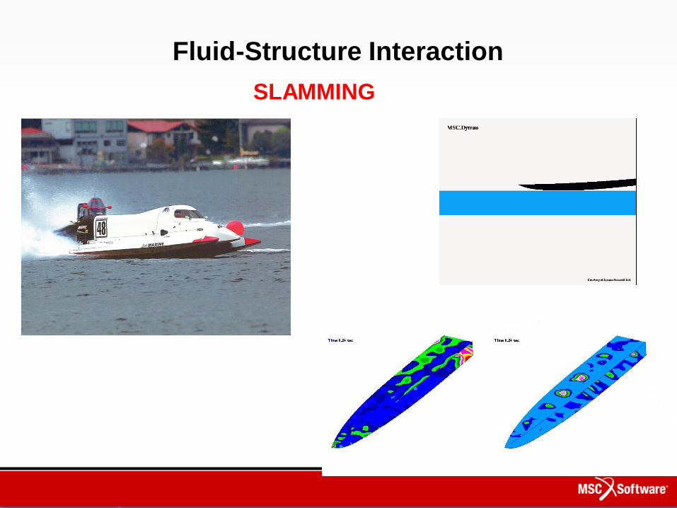
SLAMMING
Fluid-Structure Interaction

Acoustic Simulation
• Solve problems involving structures that
contact fluid, liquid or gas.

Noise on a Ship
• Low-frequency Noise
– Discretion (exterior noise):
• Propeller noise
• Hull radiation
• Muffler noise
• Etc.
– Crew comfort (interior noise):
• Diesel engine noise
• Turbulence noise
• Room-to-room insulation
• Etc.
• High-frequency Noise
– Sonar:
• Tonpilz transducer
• Sonar array

Propeller Fairing
• This case study shows propeller noise radiation in sea water and
the acoustic treatment effects on the rudders
• Lafayette Class Frigate from French Army
• The vicinity of the propeller is modelled
50 m 30 m
15 m
130 m16 m

• An admittance boundary
condition
– To model acoustic treatment on
the rudders
• Incident spinning duct modes
– To account for the real propeller
noise source
• a zero pressure BC on the
interface
– the air/water interface
• Infinite acoustic elements
– allows to compute for the far
field radiation
Key features

With a treatment on the
Rudders
• Virtual microphone are placed on an arc 40m far from the hull (in
infinite element domain)
Results – Pressure field
No treatment on the
Rudders
Directivity in the far field
The maximum noise is reduced by 3dB
The treatment modifies the directivity

3 m
Large Diesel Engine Noise
• This case study presents the radiation of a large ship engine
• This marine diesel engine has the following characteristics:
– 16V cylinders
– maximum regime: 1800 RPM
– Max Power 4320KW ( or 5900CV )
• The acoustic model is designed to reach 1000Hz (order 33 of RPM 1800)

Standard Computation Process
3. Post Processing and Analysis
FRF
s
Waterf
all
Maps Waterfall
1. Vibration computations 2. Acoustic computations
Import vibration
results
+ Restart Capability !!

3D Mesh Creation• There are many meshing tools on the market featuring fast 3D mesh
generation
• Wrapping functions will create for you a closed external surface
surrounding your structural model. This surface will carry the structural
information
• The 3D elements are easily generated with meshing tools
Non Reflecting
Surface
Structure model external
surface
3D acoustic
elements

Waterfall Diagram• Dedicated tool to post-process efficiently results on waterfall
diagrams
Watefall
map
SPL at fixed frequency,
varies with RPMSPL at fixed RPM,
varies with RPM

Results and Performance
• Results can be retrieved anywhere both in the finite element and in
the infinite element (beyond the non reflecting surface) with the
same high accuracy
• The acoustic power radiated by the engine can also be computed
Thanks to the fast solver
implemented into Actran, the CPU
time is around 4 min per frequency !
(RAM consumption around 1GB)

Modeling
MSC.Software 49 years in Simulation for Engineering
Multi Body DynamicsDynamic Impact
& Shock Analysis
From Design …
… To Product
MSC.Software
Virtual Product Development
Solution Thermal loads
& heat transfer
Vibration
& acoustics
Stresses &
Fatigue

THANK YOU !!!