mseg 667 nanophotonics: materials and devices 2: em wave theory prof. juejun (jj) hu...
TRANSCRIPT
MSEG 667Nanophotonics: Materials and Devices
2: EM Wave Theory
Prof. Juejun (JJ) Hu

References
Principles of Nano-optics, Ch. 2 Fundamentals of Photonics, Ch. 2 and 5 Photonics: Optical Electronics in Modern
Communications, Ch. 1 Electromagnetic Wave Theory, Ch. 1
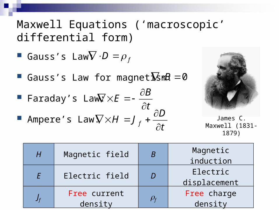
Maxwell Equations (‘macroscopic’ differential form)
Gauss’s Law:
Gauss’s Law for magnetism:
Faraday’s Law:
Ampere’s Law:
fD
0B
BE
t
f
DH J
t
James C. Maxwell
(1831-1879)
H Magnetic field B Magnetic induction
E Electric field D Electric displacement
Jf Free current density rf Free charge density

Charge conservation
Ampere’s Law:
Gauss’s Law:
Vector identity:
Charge conservation:
f
DH J
t
f
DH J
t
fD
0H
0ffJ t
0ff
S
QJ dA
t
Free electric current flowing through any enclosed surface S is equal to the change rate of free charge within the surface.
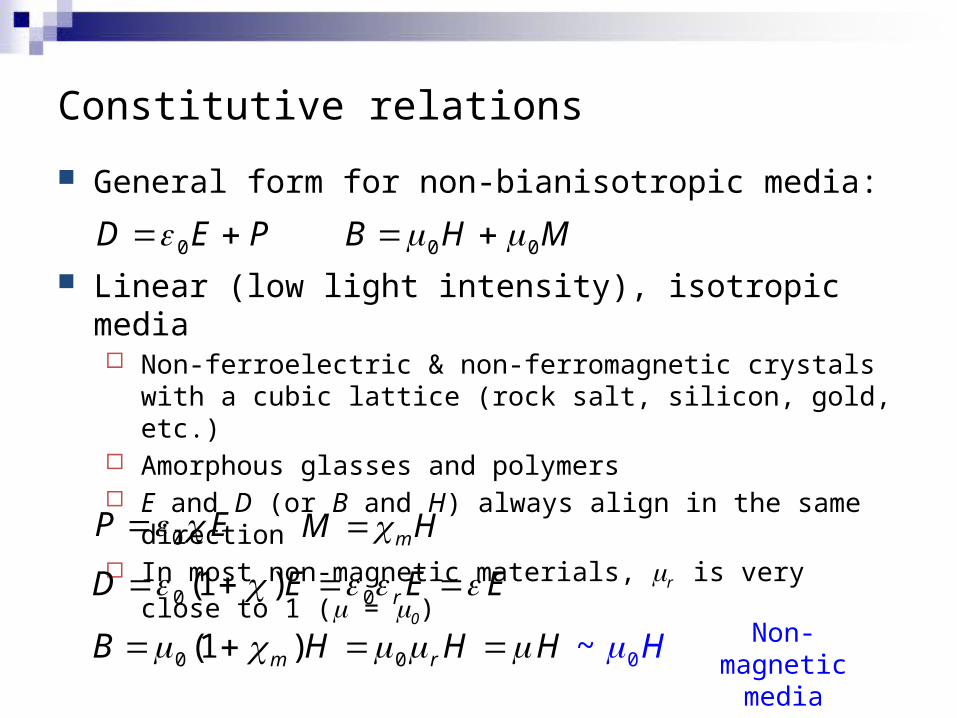
Constitutive relations
General form for non-bianisotropic media:
Linear (low light intensity), isotropic media Non-ferroelectric & non-ferromagnetic crystals with a cubic
lattice (rock salt, silicon, gold, etc.) Amorphous glasses and polymers E and D (or B and H) always align in the same direction In most non-magnetic materials, mr is very close to 1 (m = m0)
0D E P 0 0B H M
0P E mM H
0 0(1 ) rD E E E
0 0 0) ~(1 m rB H H H H Non-magnetic media
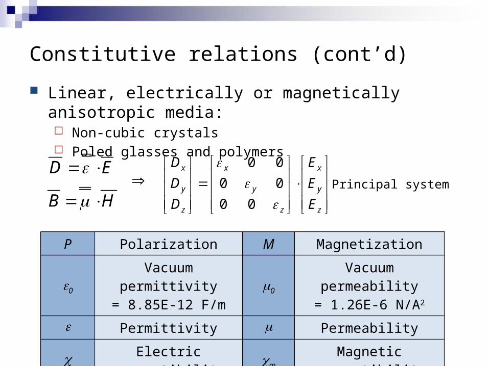
Constitutive relations (cont’d)
Linear, electrically or magnetically anisotropic media: Non-cubic crystals Poled glasses and polymers
P Polarization M Magnetization
e0Vacuum permittivity
= 8.85E-12 F/mm0
Vacuum permeability= 1.26E-6 N/A2
e Permittivity m Permeability
c Electric susceptibility cm Magnetic susceptibility
D E
B H
0 0
0 0
0 0
x x x
y y y
z z z
D E
D E
D E
Principal system

Transparent polycrystalline ceramics
Typical opacity of polycrystalline materials: scattering
Sources of scattering Grains with different orientations Inter-grain secondary phases
LumiceraTM, Murata Inc. Solution: Cubic lattice material (isotropic) Processing optimization to eliminate
secondary phases
Advantages Superior mechanical strength High refractive index and damage
threshold Spinel structure (cubic)

Wave equation in source-free, isotropic media
Source-free, isotropic media:
Vector identity
Wave equation (vectorial equation: 6 equations total)
B HE
t t
D EH
t t
0fJ
2
2
EE
t
2 2E E E E
0f
22
2
2
0 2
EE
t
E
t
Non-magnetic media

Helmholtz equation for monochromatic waves
Wave equation:
Monochromatic wave: single angular frequency w
Helmholtz equation:
, expE r t E r i t
22
2
,,
E r tE r t
t
2 2 0E r
Complex amplitude
Define1
c
2k
c
wave velocity
wave number (a scalar)
2 2 0k E r
Monochromatic plane wave solution
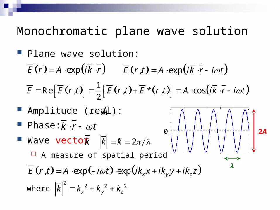
Plane wave solution:
Amplitude (real): Phase: Wave vector :
A measure of spatial period
expE r A ik r
k 2k k
, expE r t A ik r i t
1Re , , * , cos
2E E r t E r t E r t A ik r i t
0 2Ak r t
A
l , exp exp x y zE r t A i t ik x ik y ik z
where2
2 2 2x y zk k k k

Monochromatic plane wave solution (cont’d)
The surfaces of constant phase (wave front) are parallel planes perpendicular to the wave propagation direction
k r t Phase:
k r t const
0 2A
l
x x
const t constx ct
k k
xk kExample:
A set of parallel planes moving along the x-axis at the velocity of c
Wave front:
x
y
z
Monochromatic plane wave solution (cont’d)
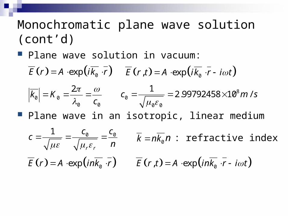
Plane wave solution in vacuum:
Plane wave in an isotropic, linear medium
0expE r A ik r
0 00 0
2k K
c
0, expE r t A ik r i t
80
0 0
12.99792458 10 /c m s
0 01
r r
c cc
n n : refractive index0k nk
0, expE r t A ink r i t 0expE r A ink r
Refractive indices of materials
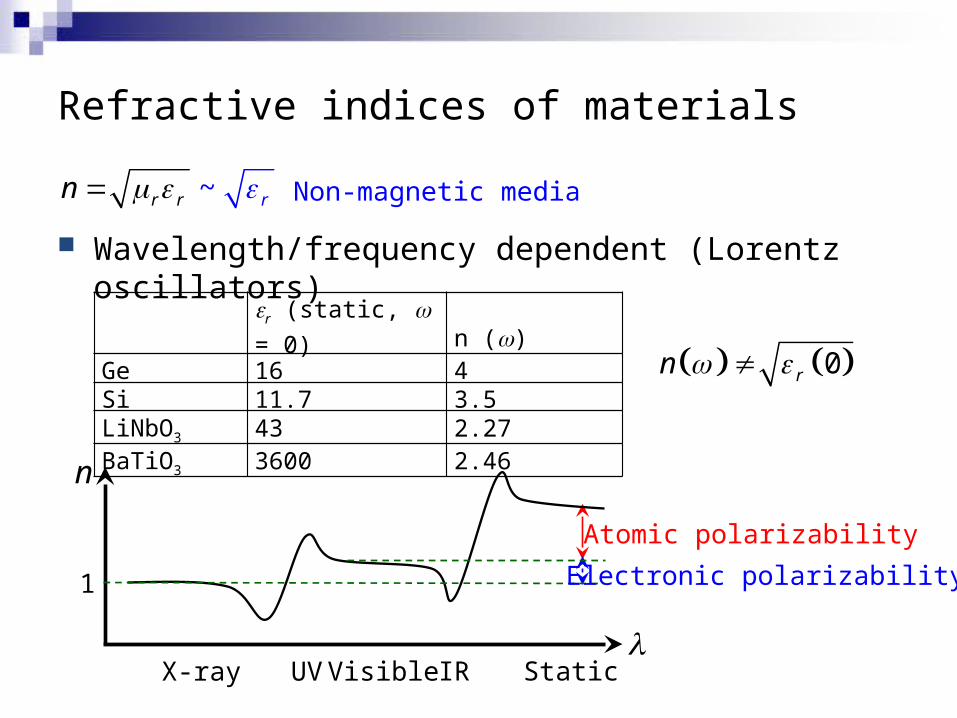
Wavelength/frequency dependent (Lorentz oscillators)
~ rr rn Non-magnetic media
r (static, w = 0) n ()Ge 16 4Si 11.7 3.5LiNbO3 43 2.27BaTiO3 3600 2.46
0rn
l
n
IRVisible StaticUVX-ray
1 Electronic polarizability
Atomic polarizability
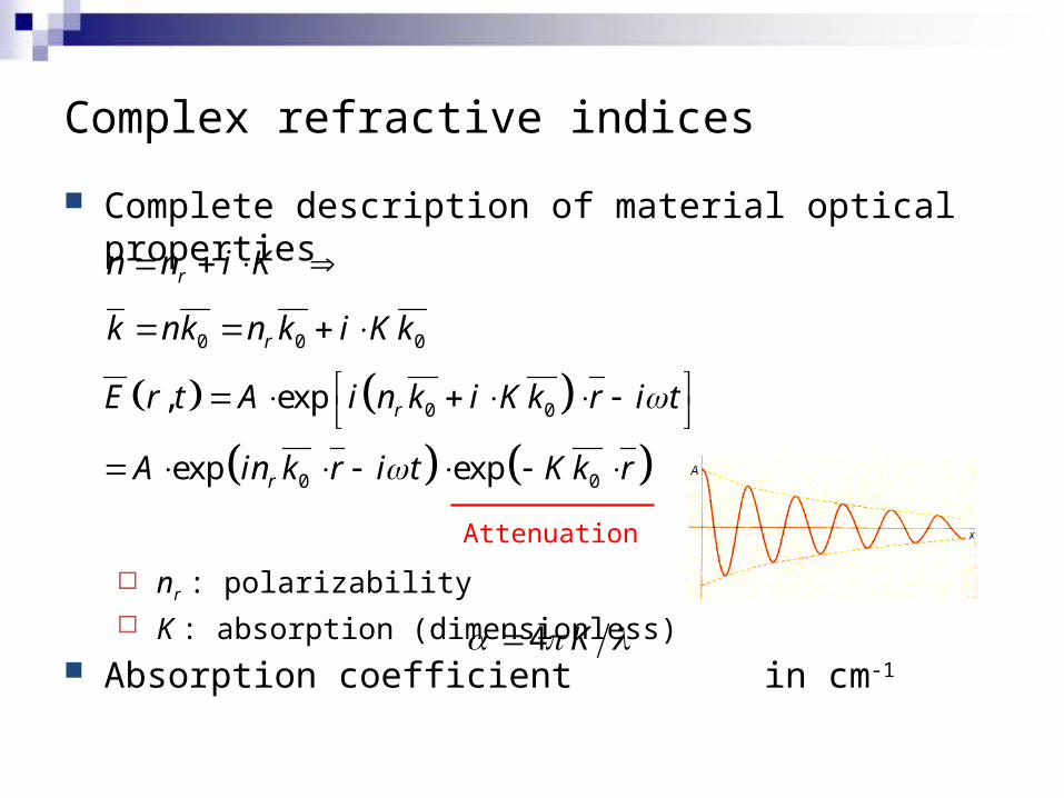
Complete description of material optical properties
nr : polarizability K : absorption (dimensionless)
Absorption coefficient in cm-1
Complex refractive indices
rn n i K
0 0 0rk nk n k i Kk
0 0
0 0
, exp
exp exp
r
r
E r t A i n k i Kk r i t
A in k r i t Kk r
Attenuation
4 K
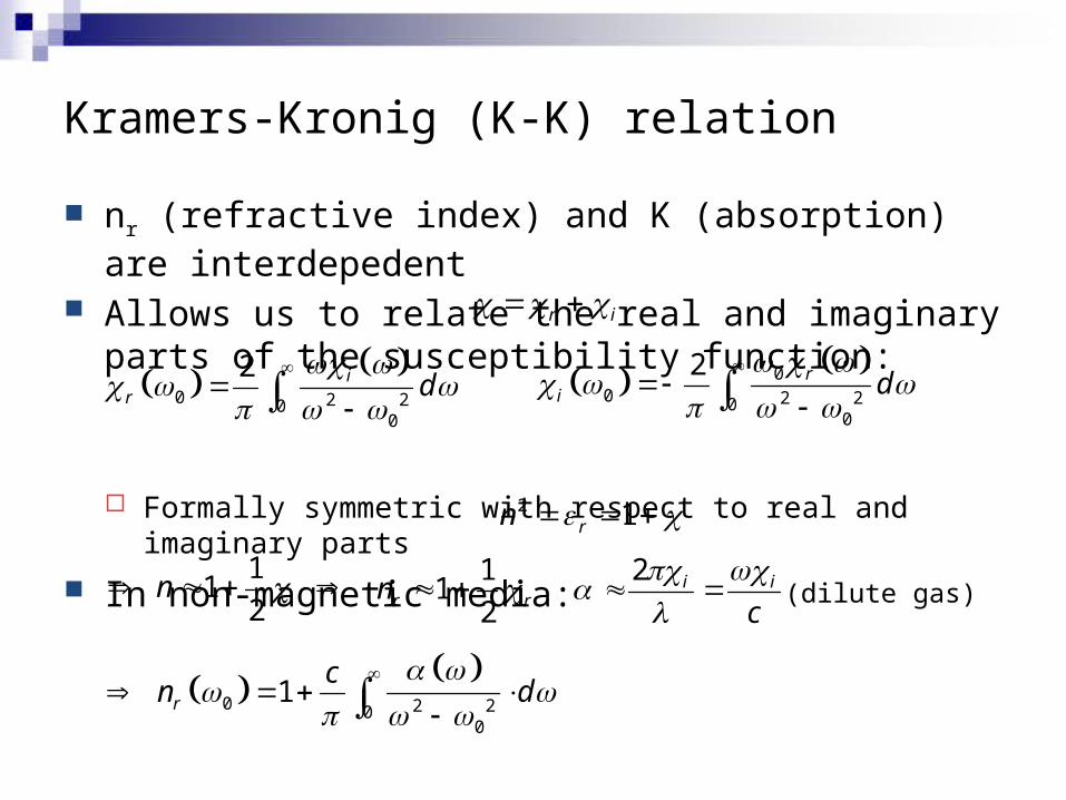
Kramers-Kronig (K-K) relation
nr (refractive index) and K (absorption) are interdepedent Allows us to relate the real and imaginary parts of the
susceptibility function:
Formally symmetric with respect to real and imaginary parts
In non-magnetic media:
0 2 20
0
2 ir d
r i
00 2 20
0
2 ri d
2 1rn
1
12
n 112r rn
2 i i
c
(dilute gas)
0 2 20
0
1r
cn d
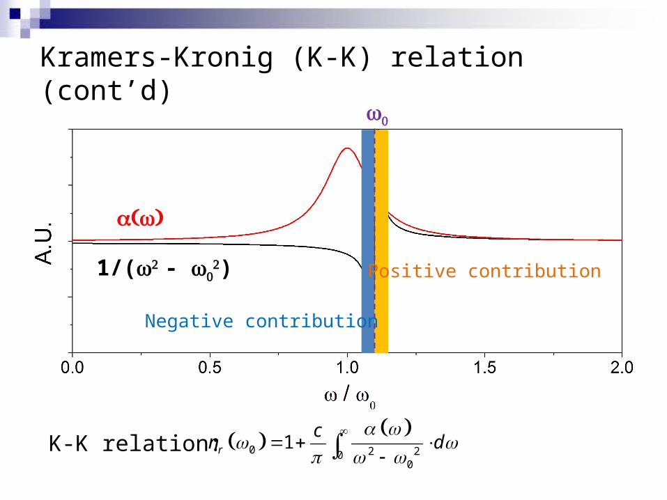
Kramers-Kronig (K-K) relation (cont’d)
( )a w
1/(w2 - w02)
w0
0 2 20
0
1r
cn d
K-K relation:
Negative contribution
Positive contribution
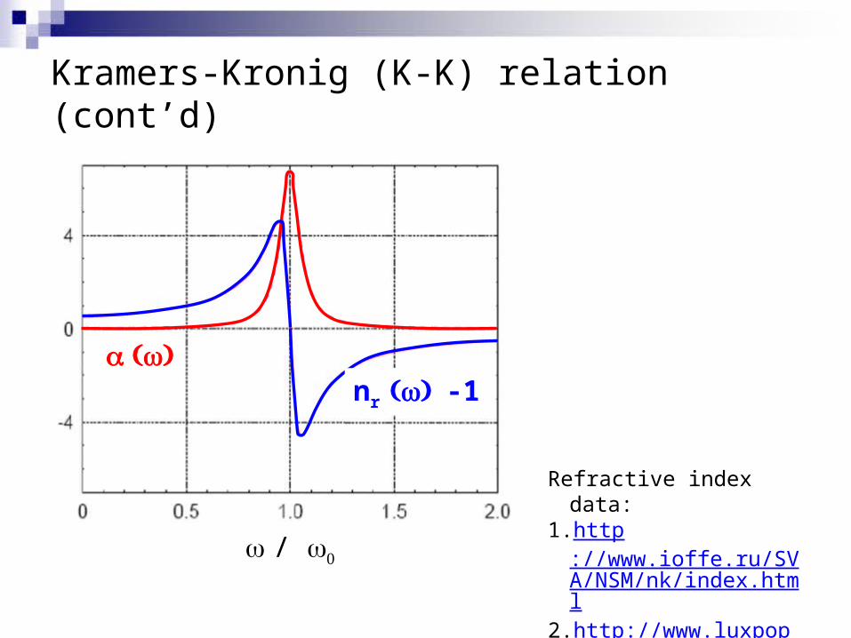
Kramers-Kronig (K-K) relation (cont’d)
w / w0
a ( )wnr ( ) w -1
Refractive index data:1. http
://www.ioffe.ru/SVA/NSM/nk/index.html
2. http://www.luxpop.com/

Increasing nr via quantum coherence
High refractive index material is attractive for a number of applications, e.g. high NA immersion photolithography
Is refractive index enhancement always accompanied by absorption increase?
Theoretical proposal: M. Scully, “Enhancement of index of refraction via quantum coherence,” Phys. Rev. Lett. 67, 1855 (1991).Experimental realization: N. Proite et al., “Refractive Index Enhancement with Vanishing Absorption in an Atomic Vapor” Phys. Rev. Lett. 101, 147401 (2008).
(K) (n)

Transmission through dielectric interfaces
Boundary conditions of fields The conditions have to be satisfied everywhere and at all
times on the boundary
Derivation of Snell’s law Phase matching: continuity of
E-field across the boundaries
)exp()exp( zikxiktiAE zx
)exp()exp()exp( ,22,33,11 xikExikExikE xxx
|||||| 22
131 k
n
nkk sin|| kkx 1
2
2
1
sin
sin
n
n
Snell’s law
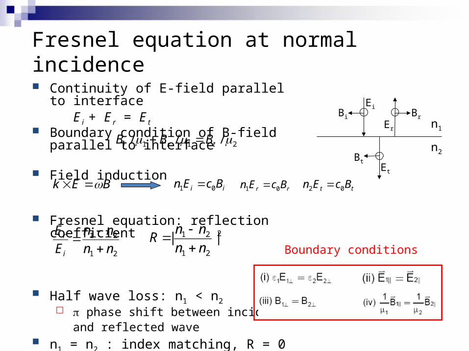
Fresnel equation at normal incidence
Continuity of E-field parallel to interfaceE i + E r = E t
Boundary condition of B-field parallel to interface
Field induction
Fresnel equation: reflection coefficient
Half wave loss: n1 < n2 p phase shift between incident
and reflected wave n1 = n2 : index matching, R = 0
Bi Br
Bt
Ei
Er
Et
n1
n2
BEk ii BcEn 01 rr BcEn 01 tt BcEn 02
21
21
nn
nn
E
E
i
r
2
21
21 ||nn
nnR
Boundary conditions
211 /// tri BBB
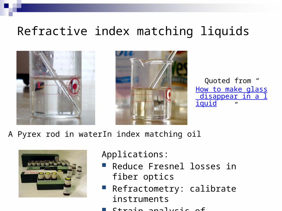
Refractive index matching liquids
A Pyrex rod in water In index matching oil
Quoted from “How to make glass disappear in a liquid
”
Applications: Reduce Fresnel losses in fiber optics Refractometry: calibrate instruments Strain analysis of transparent materials

Refractive index of gold
n ~ 0.37 @ 1 eV
Experimental value: R > 90%
%21|37.01
37.01| 2
R
Why is that ???Imaginary part of index n (extinction
coefficient) contributes to reflection as well!

TE/TM wave optical reflection
TE (transverse electric, s-polarized) polarization Electric field parallel to substrate surface
TM (transverse magnetic, p-polarized) polarization Magnetic field parallel to substrate surface
low index high index high index low index
TETM
TETM
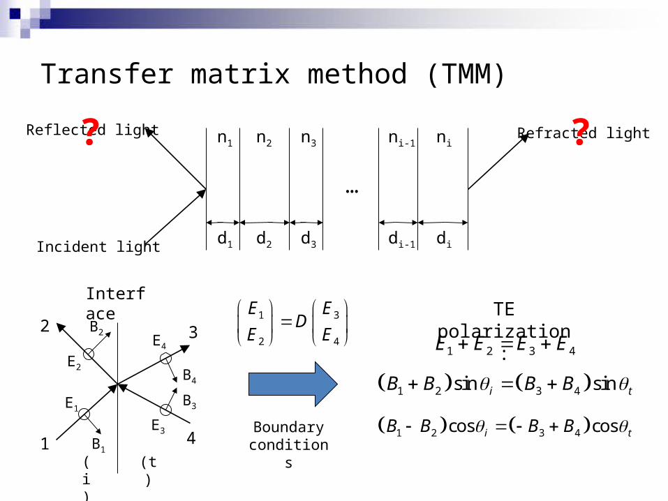
Transfer matrix method (TMM)
n1 n2
d1 d2
n3
d3
…
ni-1
di-1
ni
diIncident light
Reflected light Refracted light? ?
Interface
1
2
4
3
Boundary conditions
1 3
2 4
E ED
E E
E1
B1
E2
B2
E3
B3
B4
E4 1 2 3 4E E E E
1 2 3 4sin sini tB B B B
1 2 3 4cos cosi tB B B B
TE polarization:
(i) (t)

Transfer matrix method (TMM)
n1 n2
d1 d2
n3
d3
…
ni-1
di-1
ni
diIncident light
Reflected light Refracted light? ?
cos cos1 1
cos cos1
cos cos21 1
cos cos
t t t t
i i i iTE
t t t t
i i i i
n n
n nD
n n
n n
Interface matrix (TE): Interface matrix (TM):
cos cos
cos cos1
cos cos2
cos cos
t t t t
i i i iTM
t t t t
i i i i
n n
n nD
n n
n n
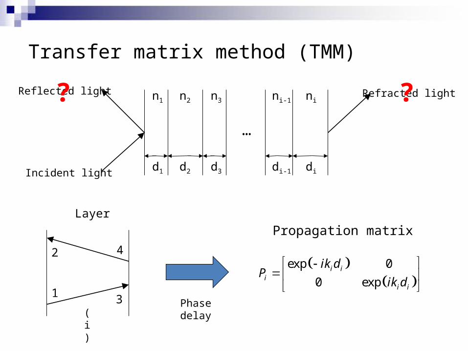
Transfer matrix method (TMM)
n1 n2
d1 d2
n3
d3
…
ni-1
di-1
ni
diIncident light
Reflected light Refracted light? ?
Layer
1
2
3
4
Propagation matrix
Phase delay
exp 0
0 expi i
ii i
ik dP
ik d
(i)
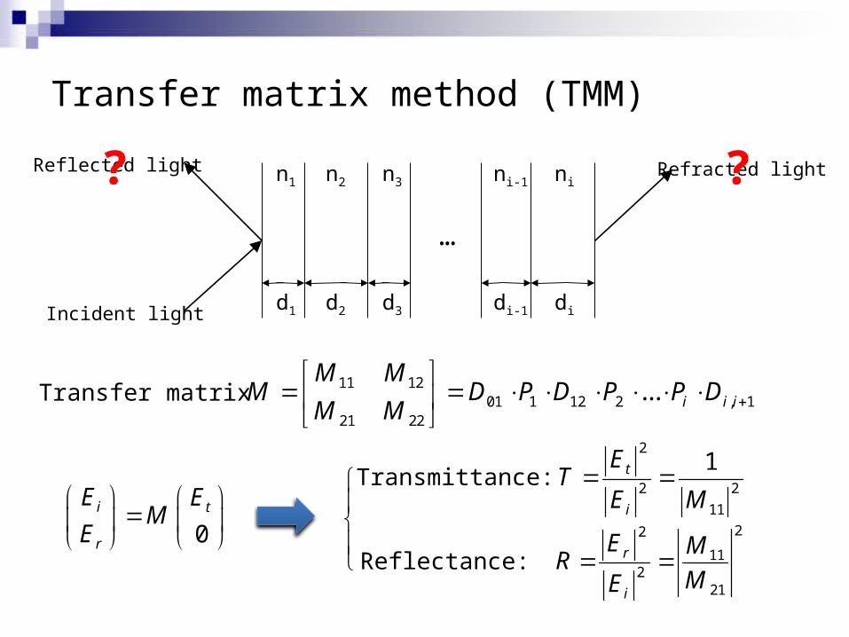
Transfer matrix method (TMM)
n1 n2
d1 d2
n3
d3
…
ni-1
di-1
ni
diIncident light
Reflected light Refracted light? ?
Transfer matrix 11 1201 1 12 2 , 1
21 22
... i i i
M MM D P D P P D
M M
0i t
r
E EM
E
22
112
21
r
i
E MR
ME
2
2 2
11
1t
i
ET
E M Transmittance:
Reflectance:

Practical considerations in TMM applications
Anisotropic and magneto-optical media S. Teitler and B. Henvis, "Refraction in Stratified, Anisotropic Media,"
J. Opt. Soc. Am. 60, 830-834 (1970). H. Kato, T. Matsushita, A. Takayama, M. Egawa, K. Nishimura, and M.
Inoue, "Theoretical analysis of optical and magneto-optical properties of one-dimensional magnetophotonic crystals," J. Appl. Phys. 93, 3906-3911 (2003).
Thick samples (compared to coherent length of light) C. Katsidis and D. Siapkas, "General Transfer-Matrix Method for
Optical Multilayer Systems with Coherent, Partially Coherent, and Incoherent Interference," Appl. Opt. 41, 3978-3987 (2002).
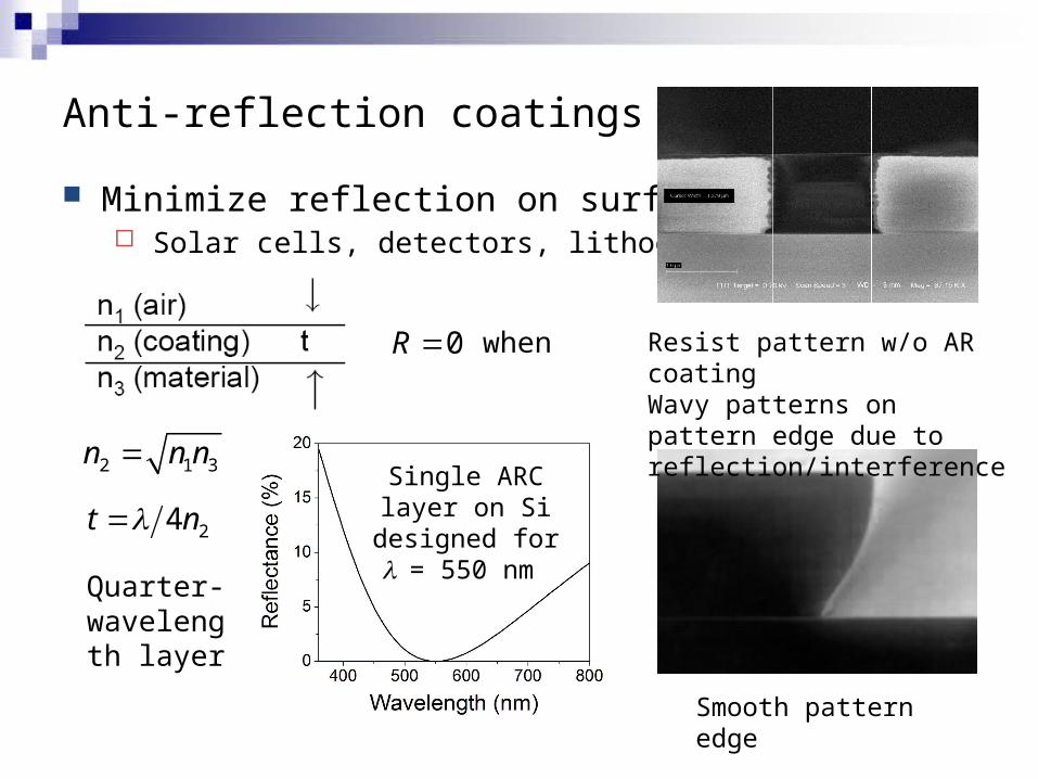
Anti-reflection coatings (ARCs)
Minimize reflection on surfaces Solar cells, detectors, lithography
Resist pattern w/o AR coatingWavy patterns on pattern edge due to reflection/interference
Smooth pattern edge
0R when
2 1 3n n n
24t nSingle ARC layer on Si designed for l = 550 nm
Quarter-wavelength
layer
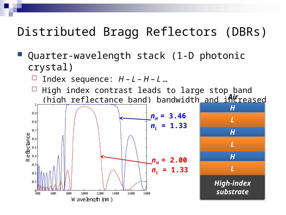
Distributed Bragg Reflectors (DBRs)
Quarter-wavelength stack (1-D photonic crystal) Index sequence: H – L – H – L … High index contrast leads to large stop band (high reflectance
band) bandwidth and increased reflectance
H
L
H
L
H
L
High-index substrate
Air
400 600 800 1000 1200 1400 1600 18000
0.1
0.2
0.3
0.4
0.5
0.6
0.7
0.8
0.9
1
Wavelength (nm)
Ref
lect
ance
nH = 3.46nL = 1.33
nH = 2.00nL = 1.33
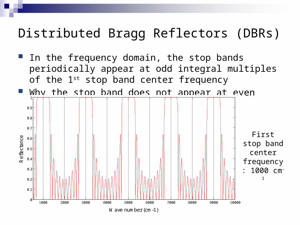
Distributed Bragg Reflectors (DBRs)
In the frequency domain, the stop bands periodically appear at odd integral multiples of the 1st stop band center frequency
Why the stop band does not appear at even multiples?
1000 2000 3000 4000 5000 6000 7000 8000 9000 100000
0.1
0.2
0.3
0.4
0.5
0.6
0.7
0.8
0.9
1
Wave number (cm-1)
Re
flect
an
ce
First stop band center frequency: 1000 cm-1

Poynting vector and energy flux
Energy flux of electromagnetic waves:
Time-averaged energy flux:
, ,S E H E r t H r t
2
0
1, , Re *
2 2S E r t H r t dt E r H r
E
HS, k