msg ms1000+ - steering.com.ua ms1000+ user manual.pdf · user manual msg ms1000+ test bench for...
TRANSCRIPT

USER MANUAL
MSG MS1000+TEST BENCH FOR DIAGNOSTICS OF SHOCK
ABSORBERS MSG MS1000+
2017.05.17
QU
ALI
TYU
NIQ
UEN
ESS
INN
OVA
TIO
NTR
AIN
ING
SER
VICE
WA
RR
AN
TY

User Manual - Test bench MSG MS1000+
2
INTRODUCTION .......................................................................................................................................................... 3
1. SAFETY MEASURES ............................................................................................................................................. 3
2. DESCRIPTION AND OPERATION ....................................................................................................................... 5 2.1 Test bench description and operation ............................................................................................... 6
2.1.1 Technical characteristics................................................................................................................ 62.1.2 Packing and equipment set.......................................................................................................... 72.1.3 Installation location ....................................................................................................................... 72.1.4 Test bench construction and operation ................................................................................... 7
2.2 Test bench component parts description and operation ............................................................. 8 2.2.1 General information and working chamber operation ...................................................... 82.2.2 Pneumatic clamp adjustment..................................................................................................... 92.2.3 Lower pneumatic clamp height adjustment .......................................................................... 102.2.4 Puller stroke adjustment ............................................................................................................. 112.2.5 Shock absorber nitrogen filling block ...................................................................................... 122.2.6 Control panel ................................................................................................................................... 122.2.7 Pneumatic clamp pedal control unit ........................................................................................ 13
3. PROPER USE ......................................................................................................................................................... 13 3.1 Operating restrictions .............................................................................................................................. 13 3.2 Test bench preparation for use ............................................................................................................. 13 3.3 Test bench use ............................................................................................................................................ 14
4. TEST BENCH MAINTENANCE ............................................................................................................................. 19 4.1 Invertor maintenance ............................................................................................................................... 19 4.2 Gear motor maintenance ........................................................................................................................ 20 4.3 Air-preparation unit maintenance ....................................................................................................... 23
5. TEST BENCH RUNNING REPAIR ........................................................................................................................ 24
6. STORAGE ............................................................................................................................................................... 25
7. TRANSPORTATION ............................................................................................................................................... 27
8. TEST BENCH WASTE ............................................................................................................................................ 27
9. TEST CERTIFICATE .............................................................................................................................................. 27
CONTENTS

User Manual - Test bench MSG MS1000+
3
INTRODUCTIONWe are grateful for choosing MSG Equipment. Test bench for diagnostics of shock absorbers MSG MS1000+ (hereinafter, MS1000+) is made of high quality components and materials consisting of the latest diagnostic equipment manufacturing technologies. MS1000+ distinctive features:• diagnostics of shock absorbers of different construction types;• testing of shock absorbers under load with different speed and simulation of car in motion;• opportunity to compare testing results;• diagram creation over existed one;• saving and printing of testing results;• user-friendly software.Actual User Manual is an essential component of the test bench. It contains information on appli-cation, compound parts, functioning and construction of MS1000+, its technical characteristics and all necessary details regarding exploitation. The manufacturer reserves the right to change compo-nent parts and software without preliminary notice of users.It is strongly recommended to learn actual User Manual MS1000+ before launching the equipment, take special training at the manufacturing enterprise if necessary. Safety requirements should be strictly observed. Special attention should be paid to text with notes ‘DANGER’, ‘WARNING’ in actual User Manual. Non-observance of ‘WARNING’ instructions may cause serious consequences under certain conditions. It is necessary to follow the instructions of all sections for personnel safety. The following indications will be used in actual User Manual:
Symbol Meaning Description, recommendations, notes
WARNINGDangerous situation implying slight injury or material
damage could occur
DANGERDangerous situation implying serious injury or damage
of the test bench could occur
1. SAFETY MEASURES
DANGER

4
User Manual - Test bench MSG MS1000+
1. It is strictly forbidden to launch the test bench while gear motor unit doors are open. There is a risk to touch exposed conductive parts of electric potential up to 380V and get electric shock.2. It is strictly forbidden to conduct any connections to terminals of electric motor and invertor; open protective elements; disassemble the frame under connected supply voltage and 10 minutes after disconnection of the test bench (live capacitors save dangerous voltage in current-carrying part for some time after supply disconnection).3. It is strongly recommended to avoid disassembling, modifying or repairing the test bench per-sonally. It may cause electric shock, fire accident or other damage. Issues on repair should be di-rected to the Supplier.4. It is strictly forbidden to connect output terminals U/T1, V/T2, W/T3 to power supply as far as it will cause total destruction of invertor, fire accident or other damage, and removal of warranty li-ability by the Supplier. It is essential to check connections to avoid possible danger.5. The test bench should be effectively grounded.6. Disconnect supply of the test bench with ‘OFF/ON’ switch when it is out of use. 7. Shock absorber should not be disassembled while it is fixed in diagnostics unit. It may cause deformation of pneumatic clamp.8. Disconnect supply of the test bench before starting any maintenance works. There is a risk of electric shock.9. It is strongly recommended to avoid leaving the test bench in mode of diagnostics unattended.
WARNING
1. Disconnect power supply from the test bench in case of any failure. Long lasting current flow may lead to deflagration or damage of electric motor winding.2. MS1000+ should be used in well-ventilated premises only. Existence of vapor containing highly flammable matters in the air may cause fire accident.3. The test bench should be used in accordance with the instructions described in actual User Manual.4. It is strongly recommended to check insulation state in supply electric cable regularly.5. Mounting and dismounting of shock absorber should be conducted carefully to prevent its fall or deformation.6. Use filters to reduce electromagnetic interference degree. Otherwise, nearby electronic devices may be adversely affected by it.7. If the test bench is out of service for a long time, it is strongly recommended to inspect and check it before launching.8. Use of inappropriate computer facilities or programs will cause removal of warranty liability

5
User Manual - Test bench MSG MS1000+
(even if computer facilities or programs were shortly after removed or deleted).9. The test bench should not be altered, except the manufacturer. Use of the equipment is avail-able along with its original component parts and accessories only. Non-observance of this point will cause removal of warranty liability. Only original software is available for use on actual test bench. Besides, MSG Company is not responsible for any damage caused by installing inappropriate programs.
2. DESCRIPTION AND OPERATION2.1 Test bench description and operation
Test Bench MS1000+ is a specialized equipment item, manufactured for service centers specializing in repair and maintenance of shock absorbers for motor cars and trucks. Diagnostics of mono-tube and twin-tube gas charged shock absorbers with diverse combinations of upper and lower mount-ing. (Fig. 1).
Fig. 1 – Shock absorbers with different types of working part fittings
Diagnostics of shock absorber is conducted through dynamogram record (data on how applied force depends on shock absorber shaft position). Maximum load available is 1000 kg.Specialized pneumatic vice is used for quick, safe and easy fixing of shock absorbers of any type. The clamp controlled by PC, control panel or pedal unit.Available shock absorber testing modes: manual and automatic. Available speed options in manual mode: 60, 120, 180 rpm. Available speed options in automatic mode: up to 6 free speed options. Testing results can be saved in a file and be set as a template for further diagnostic circles.The test bench is connection to the Internet through Wi-Fi. Software update and technical support is available through Internet connection.Nitrogen filling block for shock absorber can be optionally included in the delivery set.
Do not test shock absorbers with spring, it may cause damage of the test bench.

6
User Manual - Test bench MSG MS1000+
Name Value
Voltage, V 380±10%
Power supply, kW 3.7
Supply type Three-phase (3L+N+PE)
Dimensions W×D×H, mm 2460×1042×482
Weight, kg 350
Clamp control Pneumatic
Test bench pneumatic system power pressure, bar 6
Requirements to pressed air of test bench pneumatic system
Cleaned air, no need in air-oil lubricator. Setting of 25 µm centrifugal filter pro-viding air purity class on the standard ISO 8573-1:2010 [7:8:4] is required
Shock absorber testing
Shock absorber shaft stroke Adjustable
Shock absorber shaftstroke adjustment Manual
Shock absorber shaftstroke adjustment range, mm 0-140
Height adjustment of shock absorber fixing Manual
Bound/rebound maximum load, kg 1000
Operation mode Manual/automatic
Quantity of testing modes 1-6
Testing modes (by default)
Speed 1 – 30 rotationsSpeed 2 – 60 rotationsSpeed 3 – 90 rotationsSpeed 4 – 120 rotationsSpeed 5 – 150 rotations Speed 6 – 180 rotations
Output parameters– Bound/rebound– Shock absorber temperature– Shock absorber stroke
Print output data Yes
Connection to the Internet Wi-Fi (802.11 a/b/g/ac)
2.1.1 Technical characteristics

7
User Manual - Test bench MSG MS1000+
2.1.2 Packing and equipment setThe test bench is delivered safely packed in a strong box for equipment transportation. It is essen-tial to inspect the test bench and check it for damage after its unpacking. Packing materials are to be wasted totally: place it in the corresponding places for separate waste collection.The manufacturer is not responsible for material damage, injury of people or animals occurred in consequence of non-observance of the instructions described. The equipment set includes:– Test Bench MS1000+;– Set of changeable fittings for shock absorber – 3 pairs;– Handle for fixing pneumatic clamp lock nuts – 1 piece;– Universal prism for fixing shock absorbers with rod end – 2 pcs +1 piece with uncalibrated holes (for shock absorber with irregular shafts);– Pneumatic clamp pedal control unit (optionally);– Shock absorber nitrogen filling block (optionally);– User Manual for Test Bench MS1000+.
2.1.3 Installation locationThe test bench does not require mounting to the foundation due to its construction and has inclina-tion up to ±0,1%.
2.1.4 Test bench construction and operation
Fig. 2 – Test Bench MS1000+ (front view)

8
1 – working unit; 2 – mechanical unit; 3 – shock absorber nitrogen filling block1; 4 – display; 5 – control panel; 6 – electrical unit; 7 – pneumatic clamp pedal control unit2.
User Manual - Test bench MSG MS1000+
Initial connection of the test bench implies application of the following fittings and connectors:- electric line – socket 3P+PE+N 16A, 380В, IP-44 stationary IEK;- pneumatic line – quick disconnect coupling 5180 G1/4 (Camozzi);- nitrogen filling block – quick disconnect coupling 5480 8/6 (Camozzi).
The manufacturer is not responsible for incorrect indication of measuring due to application of inappropriate connectors.
2.2 Test bench component parts description and operation2.2.1 General information and working chamber operation
Fig. 3 – Working chamber
1 – pneumatic upper clamp; 2 – pneumatic lower clamp (Fig. 4); 3 – lower clamp lock with fixation; 4 – rotation wheel; 5 – puller threaded part lock; 6 – temperature sensor.
1Delivered optionally.
2Delivered optionally.

9
User Manual - Test bench MSG MS1000+
Upper and lower pneumatic clamps (1, 2) arepneumatic cylinders, used for fixation of tested shock absorber.Lower clamp lock with fixation (3) is used for fixing of lower clamps with regard to puller rotation wheel.Shaft threaded part lock (5) is used for lift lockout of lower clamp mechanism along pullerthreaded joint.
Fig. 4 – Pneumatic lower clamp1, 4 – pullers; 2, 3 – shock absorber changeable fittings.
Fig. 5 – Shock absorber changeable fittings
Adjustment is conducted in order to synchronize stroke of pullers of pneumatic clamps.Adjustment is carried out with throttles (Fig. 6) through changing of speed of pneumatic cylinder air filling.
2.2.2 Pneumatic clamp adjustment

10
User Manual - Test bench MSG MS1000+
Fig. 6 – Position of adjusting throttleson pneumatic clamps (bottom view on upper clamps)
Take the following steps to adjust height of lower pneumatic clamps:– Unblock threaded lock (1) by 90 degrees turn (Fig. 7).– Unblock lower pneumatic clamp lock (2).– While turning rotation wheel (3), set a needed height of pneumatic clamps.– On finishing adjustment of height of lower pneumatic clamps, block threaded lock and clamp lock.
2.2.3 Lower pneumatic clamp height adjustment
Fig. 7 – Strokecontrol of lower pneumatic clamps
1 – air exhaust throttle; 2 – air supply throttle to pneumatic cylinder.
1 – threaded lock; 2 – lower pneumatic clamp lock; 3 – rotation wheel.

11
User Manual - Test bench MSG MS1000+
Puller stroke adjustment mechanism is used for setting operating stroke (motion range) of puller depending on tested shock absorber type.Position sensor is used for indication of puller stroke and location at the moment.
2.2.4 Puller stroke adjustment
Fig. 8 – Puller stroke adjustment unit
1 – bearing; 2 – puller stroke adjustment mechanism; 3 – puller; 4 – position sensor; 5 – puller shaft mechanism fixing screws.

12
User Manual - Test bench MSG MS1000+
2.2.5 Shock absorber nitrogen filling block
Fig. 9 – Shock absorber filling block1 – cylinder nitrogen pressure indicator; 2 – line pressure indicator; 3 – nitrogen cylinder; 4 – gear;
5 – filling coupling nitrogen pressure control; 6 – filling coupling.
Fig. 10 – Control panel1 – 'OFF/ON' switch; 2 – 'EMERGENCY' button; 3 – pneumatic clamp control buttons.
2.2.6 Control panel
'OFF/ON' switch (1) is used for test bench activation/deactivation.'EMERGENCY' button (2) is used for test bench emergency stop.Pneumatic clamp control buttons (3) are used for regulation of upper and lower pneumatic clamps.

13
User Manual - Test bench MSG MS1000+
2.2.7 Pneumatic clamp pedal control unit
Fig. 11 – Pneumatic clamp pedal control unitPneumatic clamp pedal control unit is used as a backup mechanism of pneumatic clamp control. This feature gives an opportunity to mount tested unit with both hands.
3. PROPER USE3.1 Operating restrictions
It is strongly recommended to use computer and other active network connections, included in the equipment set, in indoor heated premises under stable climatic environment. Computer, invertor and active network connections operate at temperatures from +1°С to +30°С, under atmosphere relative humidity - from 10 to 90% at temperature +30°С (without water condensation).Computer and other active network connections, included in the equipment set, withstand short (3-5 sec.) static vertical load on the frame up to 0,25 kg/cm2 under total load on the frame up to 80 kg, except interface and power connectors. Test Bench MS1000+ is resistant to electrostatic discharge, network voltage dynamic changes, high-energy microsecond impulse interference in power supply circuit.
3.2 Test bench preparation for useRemove shipping foam packing.Do not take the test bench in the place of opening parts and perforation on relocating it. Install the test bench on solid and flat floor surface. Make sure that all four legs stand firmly on the floor and the test bench is installed strictly vertically (use leveling gauge). The surface should withstand pressure up to 2500 Pa spread on the area of 1,5 m2.

14
User Manual - Test bench MSG MS1000+
Connect the test bench to pressed air system. Power pressure 6-10 bar.Inspect the test bench for existence of damage. If it is found, contact either the manufacturer or trade representative before launching the equipment.
In case of obvious damage, use of equipment is forbidden.
3.3 Test bench use1. Install a specialized tool - prism adapter on tested shock absorber if necessary. Fix shock ab-sorber upper fitting in upper clamps and press ‘Close upper clamp’ on the display ( ), or control panel (Fig. 12).
Open pneumatic clamps only when doors are open and motor is stopped.Testing of shock absorber is forbidden when working unit door is open.
Fig. 12 – Upper clamp closing2. Adjust height with lower clamps adjustment system (Fig. 7). In this regard, unblock threaded lock (1) and lower clamp lock (2), set the needed height with Rotation wheel (3). Fix shock absorber lower fitting with ‘Close lower clamp’ button on the display ( ) or with control panel (Fig. 13).
Always fix shock absorber safely. Poorly fixed shock absorber will show incorrect re-sults and may damage the equipment.

15
User Manual - Test bench MSG MS1000+
Fig. 13 – Lower clamp closing3. Use rotation wheel to bring shock absorber into functional area and block locks (Fig. 14). Press the button ‘Test turnover’ on the display to make sure that shock absorber is mounted within its operating stroke. The motor will make 2 turns at minimum speed.
Operator’s hand should be placed on emergency button to stop the motor immediately in case of irregular operation during test turnover.
Fig. 14 – Shock absorber functional area adjustment
4. When test turnover passes successfully, calibrate force sensor in zero value (Fig. 15).

16
User Manual - Test bench MSG MS1000+
Fig. 15 – Force sensor zero calibration (sensor value is highlighted)2 testing modes are active after zero calibration: manual and automatic (Fig. 16). Fix temperature sensor (if necessary) to shock absorber with zip tie before testing.
Fig. 16 – Testing mode selection
3 speeds are available in manual testing: 60, 120 and 180 rpm. Corresponding graphs will be recorded after motor reaches the needed speed. Free velocity can be set with the buttons «+» and «-». Free velocity graph will be displayed as ‘Manual’.Corresponding force values will be displayed on ‘Bound’ and ‘Rebound’ indicators (Fig. 17).

17
User Manual - Test bench MSG MS1000+
Fig. 17 – Shock absorber manual testing mode
Set testing program before shock absorber automatic testing. Press the button ‘Settings’ in the main menu (Fig. 18), where speed and rotation is set for every testing procedure (in upper left side of the screen). Quantity of testing modes: from 1 to 6.In settings menu preferable measuring units, operator and company name, language can be set, hardware part operation can be checked as well.
Fig. 18 – Settings window

18
User Manual - Test bench MSG MS1000+
Automatic testing (Fig. 19) has the opportunity to compare testing results with the previous ones. In this regard, press the button ‘Open’ and select previously saved data. Results will be loaded in the table and graphs. Testing settings also change (speed and quantity of testing modes). Previously received graphs become inactive after pressing the button ‘Start’, previous results will be displayed in the table in brackets, new values will be displayed without brackets.
Fig. 19 – Automatic testingUse corresponding buttons to save and print the results.There is an opportunity to compare testing results any time. Press 'Testing results’ in the main menu. There are 2 fields in the appeared window (Fig. 20) where testing results of different shock absorbers are downloaded. Results can be all together and separately printed.
Fig. 20 – Testing results window
19
User Manual - Test bench MSG MS1000+
Shock absorber is dismounted from the test bench in reverse order when testing is finished.
4. TEST BENCH MAINTENANCETest Bench 1000+ is intended for long lasting operation under twenty-four-hour schedule. However, it is essential to inspect the test bench and observe preventive measures described below with recommended intervals for trouble-free enduring operation. Inspection and preventive measures should be carried out by a qualified specialist.
Danger of injury due to immediate test bench launch.• Switch off and disconnect the test bench, block it to prevent its unintended use!
Special attention should be paid to the following aspects of daily inspection:– appropriate operation of the motor (no unusual sounds, excessive heat, vibration, etc.);– appropriate environmental conditions for test bench use (temperature, humidity, air contamina-tion, vibration, etc.);– appropriate voltage range (voltage meter measuring).It is recommended to clean test bench frame with soft tissue or cloth using neutral cleaners after finishing daily operating shift. The monitor should be cleaned with microfiber cloth. It is recommended to tighten force sensor lock nut at least once per 3 months.It is recommended to oil sliding joints of puller shaft and pneumatic clamps with lithium grease ‘LITOL - 24’ at least once per 6 months.
4.1 Invertor maintenanceVFD-E up-to-date digital invertor is intended for long lasting operation under twenty-four-hour schedule.It is essential to inspect the test bench and observe preventive measures (at least once per 6 months) described below with recommended intervals for trouble-free enduring operation. Inspection and preventive measures should be carried out by a qualified specialist.
Special attention should be paid to the following aspects of daily inspection:– appropriate operation of the motor (no unusual sounds, excessive heat, vibration, etc.);– appropriate environmental conditions for test bench use (temperature, hu-midity, air contamination, vibration, etc.);– appropriate cooling system operation;– appropriate test bench operation (no unusual noise and vibration);– appropriate voltage range (voltage meter measuring).
Invertor daily inspection

20
User Manual - Test bench MSG MS1000+
Constant current link capacitors save high voltage for some time after supply disconnection. Proceed to invertor inspection 10 minutes after LED POWER on printed board is off. Use tester to make sure that residual voltage between ‘+’ and ‘-‘ terminals is less than 25 V.
Invertor inspectionfrequency
1. Invertor maintenance is available for qualified specialists only.2. Works connected with opening of protective covers and disconnection of conductors should be conducted when power supply is off! 3. Remove all metal objects (watch, rings, etc.) before proceeding to work.Use insulated tool.4. It is strictly forbidden to disassemble test bench internal components and disconnect internal connections.
General list of recommended inspections to conduct at least once per 6 months:1. Check wire fastening of power terminal blocks and remote control bar.2. Check wires, cables, their insulation for damage. Cable insulation local color change indicates on fault.3. Conduct visual inspection of invertor and make sure that there is no foreign objects inside.4. Clean radiator, power elements, construction components, control panel, connector and other parts from dirt and dust by vacuuming or air blowing under pressure 4-6 kg/cm2.5. Remember that dirt and dust may reduce invertor term of service or cause its failure.6. Check heating conditions of invertor and motor. Pay special attention to operation of fan (rotational freedom, noise, heating, contamination).7. Switch on invertor (operation without motor activation is acceptable), reform its electrolytic capacitor and confirm its functional capabilities at least once a year.Note: Non-observance of above described instructions may cause invertor premature failure.
4.2 Gear motor maintenanceFrequency Preventive measures
Every 3000 hours of operation, at least once per 6 months.
• oil level and quality check;• bearing condition check (noise in the process of operation);• visual inspection of sealing tightness.
Depends on operation conditions, at least once per 3 years.
• change of mineral oil*;• lubrication change in antifriction bearings (recom-mended);• change of cups (distributing edge displacement from shaft worn out side).
Diverse (depends on external environment).Recovery or refreshing of lacquer and corrosion-resis-tant coating.
* mineral oil CLP220 in total of 0,70 l is recommended for use as the main one.

21
User Manual - Test bench MSG MS1000+
Danger of injury due to immediate motor activation.• Switch off and disconnect invertor, block it to prevent its unintended use!
Danger of burn due to hot gear and gear oil.• Gear should cool off before lubrication!• Threaded plugs of level hole and drain should be removed very carefully.
Oil level is checked in the following way:1. Identify location of level hole and air valve according to the figure.2. Place tank under level hole.3. Remove level hole threaded plug carefully. Some oil may flow out as far as oil maximum acceptable level is higher than level hole lower edge.4. Check oil level according to the following figure and corresponding table.
Oil level check through level hole
Fig. 21 – Oil level check scheme1 – level hole; 2 – oil nominal level.
Level hole Ø Oil minimum and maximum level =x [mm]
М10 × 1 1
M12 × 1.5 1
M22 × 1.5 2
M33 × 2 2
M42 × 2 2
5. Take the following measure if oil level is insufficient:– Turn off air valve.– Conduct fresh oil refill of the same trademark up to level hole lower edge through vent hole.– Set air valve in the initial position.

22
User Manual - Test bench MSG MS1000+
6. Set level hole threaded plug in its place. Level hole threaded plug location is demonstrated below:
Fig. 22 – Gear motor scheme1 – air valve; 2 – level hole threaded plug; 3 – level hole drain.
Oil quality in gear is checked in the following way:1. Identify location of drain according to the figure of gear motor demon-strated above.2. Take oil sample through drain.3. Check oil properties:– viscosity;– transparency (it is recommended to change oil before declared term if it is turbid or contaminated in terms of visual control).4. Check oil level.
Oil quality check through drain
1. Identify location of level hole and drain of air valve according to the figure of gear motor demonstrated above.2. Place tank under level hole.3. Turn off level hole threaded plug, air valve and drain threaded plug.4. Drain all oil from gear.5. Set drain threaded plug in its place. 6. Conduct fresh oil refill of the same trademark (CLP220) through vent hole. Mixing of synthetic oils of different trademarks is forbidden.– Amount of filling oil should correspond to name plate data or mounting position (as a rule, 0,7 l for this type of gear).– Check oil level through level hole.7. Set level hole threaded plug and air valve in the initial position.
Oil change through drain and air valve hole

23
User Manual - Test bench MSG MS1000+
Use of inappropriate gear oil may cause lubrication poor quality.• Do not mix synthetic lubricants together and with mineral lubricants!
Gear antifriction bearings are covered with consistent grease. However, every time when oil is changed, it is recommended to cover antifriction bearings with fresh grease of manufacturers: Fuchs (type: Renolit CX-TOM 15) or Aral (type: Aralube BAB EP2).Recover or refresh gear motor lacquer and corrosion-resistant coating depending on external environment.
Antifriction bearingslubrication
Air-preparation unit built in MS1000+ is used for cleaning of pressed air from mechanical admix-tures; air saturation with oil vapor for operation of different components of the system, in particu-lar, clamps for shock absorber fixation. Air-preparation unit consists of the following elements:– safety valve with manual adjustment of pressure from 0,8 to 10 bar in the test bench;– pressure-regulating filter with 25 µm filtration and power pressure of 0,3÷16 bar;– air-oil lubricator with 40 cm3 oil volume, ISO VG32 oil. There is an opportunity to conduct visual control the condition of filter element and oil volume in storage facility due to construction of pressure-regulating filter and air-oil lubricator.Air-preparation unit construction is not intended for use in severe environment with concentration of solvent vapor, etc. It is recommended to conduct daily visual check for leak, cracks and other damage before launching the test bench. If some defects of the abovementioned are found, they should be fixed or removed (by replacing failed unit element).
4.3 Air-preparation unit maintenance
The test bench should be disconnected from external pressed air supply in the process of air-preparation unit maintenance.
Strainer-drier construction is used for condensate drain when it is required, it is estimated visually and depends on operation condi-tions (air humidity, etc.).– To drain condensate in manual mode, rotate the cap (A) clockwise and press upward.– When condensate is drained, pull down the cap and rotate it anticlockwise.– In half-automatic mode condensate drain is available
Half-automatic/ manual condensate drain

24
User Manual - Test bench MSG MS1000+
when there is no pressure in test bench pneumatic system. For this regard press the cap upward.– To switch from half-automatic to manual mode, rotate the cap (A) clock-wise. To switch back, rotate the cap (A) anticlockwise.
It is recommended to relieve pressure by anticlockwise turn of pressure valve.– Open tight glass by removing the cap (A).– Rotate the glass clockwise to extreme position and relocate it underneath the unit frame.– Fill the glass with ISO VG32 oil up to the mark «MAX OIL».– Fix the glass in its place and rotate it anticlockwise to extreme position. There is no need to apply too much effort to close it.– Close the glass tightly by placing the plug (A) in the initial position. Amount of air-oil lubrication can be regulated by turn of adjusting screw.
Filling of air-oil lubrication glass
Do not change air-preparation unit settings (amount of air-oil lubrication, pressure in test bench pneumatic system, etc.), except filter cleaning and oil filling.
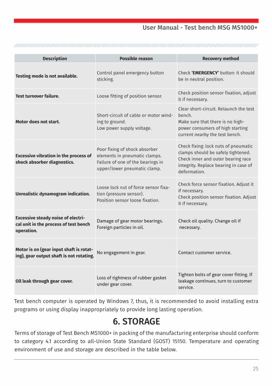
5. TEST BENCH RUNNING REPAIRPotential failures and methods of recovery are described in the table below:
Description Possible reason Recovery method
Test bench is out of operation.No power supply.Automatic cutout is off.Test bench power supply unit failure.
Check 380 V power supply. Check automatic cutout.Contact customer service.
No display respond on operator’s touch.
Touch screen is damaged. Contact customer service.
Test bench operating system load failure.
Failure in operation of test bench operating system.
Contact customer service.
Test bench diagnostics program load failure.
Failure in operation of test bench operating system.
Contact customer service.
Pneumatic clamps are out of work.No pressure in pneumatic line.Presence of capacitor in air-prepara-tion unit strainer-drier.
Check connection of external pressed air supply.Remove strainer-drier plug and drain condensate in prepared storage facility.
Left and right pneumatic clamp pull-ers asynchronous operation.
Different speed of filling of pneu-matic cylinders.
Adjust speed of filling by air exhaust and air supply throttles.
25
User Manual - Test bench MSG MS1000+
Description Possible reason Recovery method
Testing mode is not available.Control panel emergency button sticking.
Check ‘EMERGENCY’ button: it should be in neutral position.
Test turnover failure. Loose fitting of position sensor.Check position sensor fixation, adjust it if necessary.
Motor does not start.Short-circuit of cable or motor wind-ing to ground.Low power supply voltage.
Clear short-circuit. Relaunch the test bench. Make sure that there is no high-power consumers of high starting current nearby the test bench.
Excessive vibration in the process of shock absorber diagnostics.
Poor fixing of shock absorber elements in pneumatic clamps.Failure of one of the bearings in upper/lower pneumatic clamp.
Check fixing: lock nuts of pneumatic clamps should be safely tightened.Check inner and outer bearing race integrity. Replace bearing in case of deformation.
Unrealistic dynamogram indication.Loose lock nut of force sensor fixa-tion (pressure sensor).Position sensor loose fixation.
Check force sensor fixation. Adjust it if necessary.Check position sensor fixation. Adjust it if necessary.
Excessive steady noise of electri-cal unit in the process of test bench operation.
Damage of gear motor bearings.Foreign particles in oil.
Check oil quality. Change oil if necessary.
Motor is on (gear input shaft is rotat-ing), gear output shaft is not rotating.
No engagement in gear. Contact customer service.
Oil leak through gear cover.Loss of tightness of rubber gasket under gear cover.
Tighten bolts of gear cover fitting. If leakage continues, turn to customer service.
Test bench computer is operated by Windows 7, thus, it is recommended to avoid installing extra programs or using display inappropriately to provide long lasting operation.
6. STORAGETerms of storage of Test Bench MS1000+ in packing of the manufacturing enterprise should conform to category 4.1 according to all-Union State Standard (GOST) 15150. Temperature and operating environment of use and storage are described in the table below.

26
User Manual - Test bench MSG MS1000+
Function Characteristics
Operating temperature +5 … +40°С
Storage temperature -20 … +60°С
Temperature gradient 20°С
Actual air humidity in the process of operation 10 … 85% (without condensate)
Actual air humidity gradient 10% per hour
Maximum operating height (above sea level) -200 … 3000 m
Maximum operating height when transporting (above sea level)
-200 … 12 000 m
Terms of storage:
Climate zone Packing Characteristics Storage period
Temperate climate (Europe, USA, Canada,
China and Russia, except regions with tropical
climate)
Foil sealed container with absorbent and humidity indicator. [Insect and fungus protection due to
chemical treatment*].
Under shelter, snow and rain protection, absence of
vibration.
No longer than 3 years in terms of regular inspection of packing
and humidity indicator (atmosphere relative
humidity <50%).
Without packing
Indoor premises with perma-nent temperature and humid-ity (5°C<υ<60°C, atmosphere
relative humidity <50%). Absence of acute temperature
jumps and controlled ven-tilation with application of
filters (air cleaning from dirt and dust). [Absence of severe vapors and vibrations. Insect
protection*].
2 years and longer in terms of regular inspection. Check for
mechanical damage. Inspection of corrosion-resistant coating
condition.
[*] – tropical climate zone (Asia, Africa, Central and South America, Australia, New Zealand, except regions with temperate climate).In terms of planned period of storage exceeding 9 months, it is recommended to use anti corrosion additives and check air-preparation unit strainer-drier for absence of humidity and condensate. Check level of oil in gear before launching the test bench.

27
User Manual - Test bench MSG MS1000+
All elements of Test Bench MS1000+ are fixed safely, however, to prevent force sensor from deformation, it is recommended to fix upper pneumatic clamps with foam inserts between clamp and working area side walls before any type of transportation.
7. TRANSPORTATION
Do not transport the test bench with mounted shock absorber inside, it may cause deformation of pneumatic clamps.
Pay attention to the following points on Test Bench MS1000+ waste:• European Union countries – Directive 2202/96/EG [WEEE (Waste Electrical and Electronic Equipment)];• CIS countries – All-Union State Standard (GOST) ‘Resources saving. Waste treat-ment. Waste classification, identification and coding. Basic principles’ GOST 30772-2001.
Obsolete electronic devices and electrical appliances, including cables, fittings and batteries should be wasted separately from domestic garbage.• Use existing collection and recycling systems for waste disposal. • Proper waste disposal saves environment and personal health.
8. TEST BENCH WASTE
9. TEST CERTIFICATETest Bench MSG MS1000+ for diagnostics of shock absorbers meets technical requirements of
Directive 2014/30/EU - Electromagnetic Compatibility (EMC) EN Directive 2014/35/EU - Low voltage
(LVD) Directive 2006/42/EC - Machinery (MD) and is qualified for exploitation.
