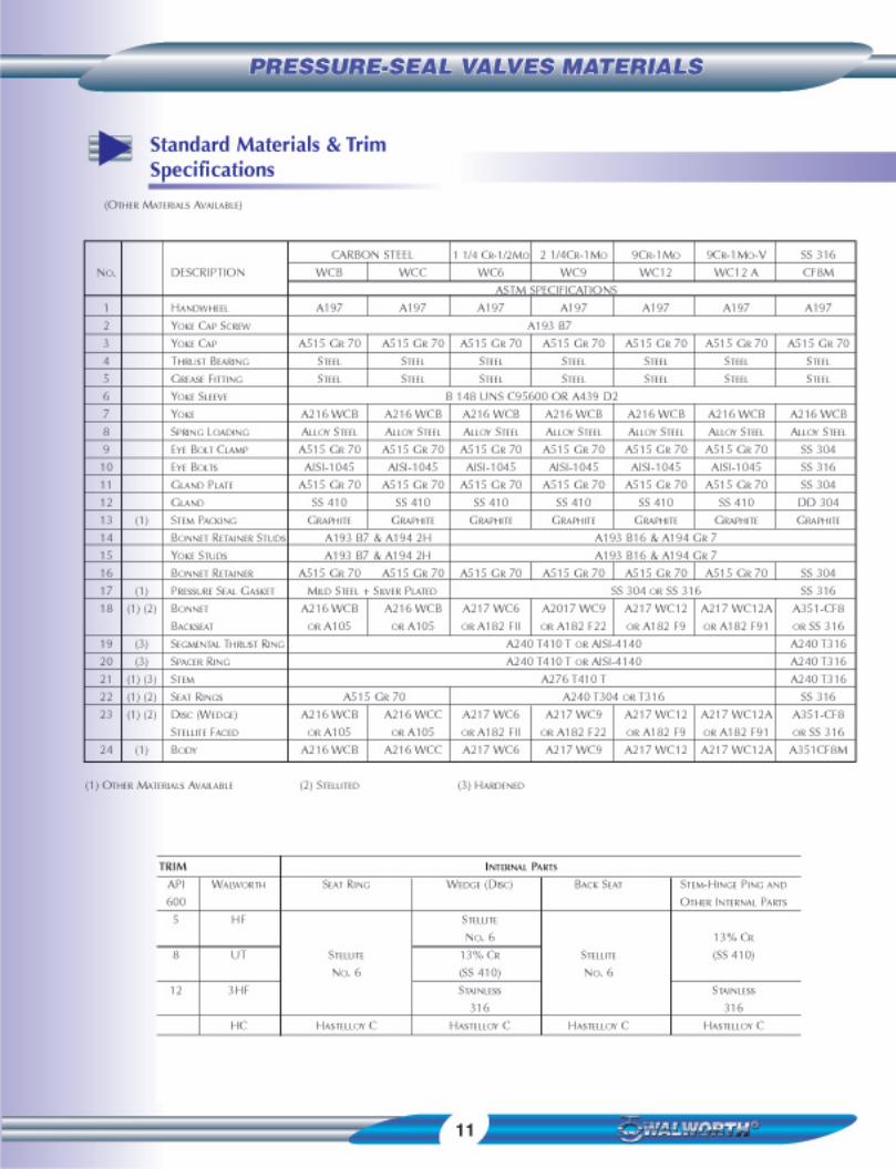
mss. nace. awwa. bsi. csa. etc. oil ... - process and … valve engineering and design ... mss....
TRANSCRIPT


PageFigure Number . . . . . . . . . . . . . . . . . . . . . . . . . . . . . . . . .IndexProduct Line . . . . . . . . . . . . . . . . . . . . . . . . . . . . . . . . . . . .IndexProfile . . . . . . . . . . . . . . . . . . . . . . . . . . . . . . . . . . . . . . . . . . . .1Walworth Valve Engineering and Design . . . . . . . . . . . . . . .2-3Flexible Wedge Gate Valves . . . . . . . . . . . . . . . . . . . . . . . . . .5Parallel Wedge Gate Valves . . . . . . . . . . . . . . . . . . . . . . . . . . .5Globe Valves . . . . . . . . . . . . . . . . . . . . . . . . . . . . . . . . . . . . .6-7Globe Stop-Check (Non-Return) Valves . . . . . . . . . . . . . . . . .7Tilting Disc Check Valves . . . . . . . . . . . . . . . . . . . . . . . . . . .8-9Piston Check Valves . . . . . . . . . . . . . . . . . . . . . . . . . . . . . . . .10Standard Materials and Trims . . . . . . . . . . . . . . . . . . . . . . . . .11Engineering and Design Options . . . . . . . . . . . . . . .12-13 & 14Accessories . . . . . . . . . . . . . . . . . . . . . . . . . . . . . . . . . . . . . .15Applicable Standards and Codes . . . . . . . . . . . . . . . . . . . . . .16Terms and Conditions . . . . . . . . . . . . . . . . . . . . . . . . . . . . . . .17
Figure Number IndexPage
5232 PS . . . . . . . . . . . . . 55247 PS . . . . . . . . . . . . . 55262 PS . . . . . . . . . . . . . 55560 PS . . . . . . . . . . . . . 55295 PS . . . . . . . . . . . . . 75301 PS . . . . . . . . . . . . . 75308 PS . . . . . . . . . . . . . 75563 PS . . . . . . . . . . . . . 75350 PS . . . . . . . . . . . . . 95353 PS . . . . . . . . . . . . . 95356 PS . . . . . . . . . . . . . 95566 PS . . . . . . . . . . . . . 95860 PS . . . . . . . . . . . . . 105540 PS . . . . . . . . . . . . . 105541 PS . . . . . . . . . . . . . 105542 PS . . . . . . . . . . . . . 10
Product LineCARBON. ALLOY & STAINLESS STEEL
CAST STEEL VALVES OS&Y
GATE VALVESCLASS FIGURE Inch 2 2 1/2 3 4 6 8 10 12 14 16 18 20 24
mm 50 65 80 100 150 200 250 300 350 400 450 500 600
600 5232 PS • • • • • • • • • • • •
900 5247 PS • • • • • • • • • • • • •
1500 5262 PS • • • • • • • • • • • • •
2500 5560 PS • • • • • • • • • • • • •
GLOBE VALVESCLASS FIGURE Inch 2 2 1/2 3 4 6 8 10 12 14 16 18 20 24
mm 50 65 80 100 150 200 250 300 350 400 450 500 600
600 5295 PS • • • • • • • • • • • •
900 5301 PS • • • • • • • • • • • • •
1500 5308 PS • • • • • • • • • • • • •
2500 5563 PS • • • • • • • • • • • • •
TILTING DISC CHECK VALVESCLASS FIGURE Inch 2 2 1/2 3 4 6 8 10 12 14 16 18 20 24
mm 50 65 80 100 150 200 250 300 350 400 450 500 600
600 5350 PS • • • • • • • • • • • •
900 5353 PS • • • • • • • • • • • •
1500 5356 PS • • • • • • • • • • • •
2500 5566 PS • • • • • • • • • • • •
PISTON CHECK VALVESCLASS FIGURE Inch 2 2 1/2 3 4 6 8 10 12 14 16 18 20 24
mm 50 65 80 100 150 200 250 300 350 400 450 500 600
600 5860 PS • • • • • • • • • • • •
900 5540 PS • • • • • • • • • • • •
1500 5541 PS • • • • • • • • • • • •
2500 5542 PS • • • • • • • • • • • •
1
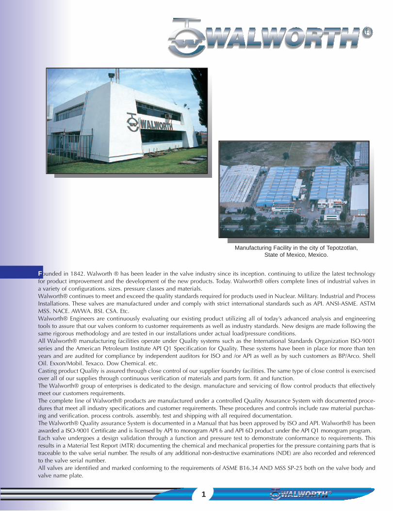
Founded in 1842. Walworth ® has been leader in the valve industry since its inception. continuing to utilize the latest technologyfor product improvement and the development of the new products. Today. Walworth® offers complete lines of industrial valves ina variety of configurations. sizes. pressure classes and materials.Walworth® continues to meet and exceed the quality standards required for products used in Nuclear. Military. Industrial and ProcessInstallations. These valves are manufactured under and comply with strict international standards such as API. ANSI-ASME. ASTMMSS. NACE. AWWA. BSI. CSA. Etc.Walworth® Engineers are continuously evaluating our existing product utilizing all of today’s advanced analysis and engineeringtools to assure that our valves conform to customer requirements as well as industry standards. New designs are made following thesame rigorous methodology and are tested in our installations under actual load/pressure conditions.All Walworth® manufacturing facilities operate under Quality systems such as the International Standards Organization ISO-9001series and the American Petroleum Institute API Q1 Specification for Quality. These systems have been in place for more than tenyears and are audited for compliance by independent auditors for ISO and /or API as well as by such customers as BP/Arco. ShellOil. Exxon/Mobil. Texaco. Dow Chemical. etc.Casting product Quality is assured through close control of our supplier foundry facilities. The same type of close control is exercisedover all of our supplies through continuous verification of materials and parts form. fit and function.The Walworth® group of enterprises is dedicated to the design. manufacture and servicing of flow control products that effectivelymeet our customers requirements.The complete line of Walworth® products are manufactured under a controlled Quality Assurance System with documented proce-dures that meet all industry specifications and customer requirements. These procedures and controls include raw material purchas-ing and verification. process controls. assembly. test and shipping with all required documentation.The Walworth® Quality assurance System is documented in a Manual that has been approved by ISO and API. Walworth® has beenawarded a ISO-9001 Certificate and is licensed by API to monogram API 6 and API 6D product under the API Q1 monogram program.Each valve undergoes a design validation through a function and pressure test to demonstrate conformance to requirements. Thisresults in a Material Test Report (MTR) documenting the chemical and mechanical properties for the pressure containing parts that istraceable to the valve serial number. The results of any additional non-destructive examinations (NDE) are also recorded and referencedto the valve serial number.All valves are identified and marked conforming to the requirements of ASME B16.34 AND MSS SP-25 both on the valve body andvalve name plate.
Manufacturing Facility in the city of Tepotzotlan,State of Mexico, Mexico.

2
Pressure Seal ValvesOutside Screw and Yoke (OS&Y)
VIEW APAGE 3
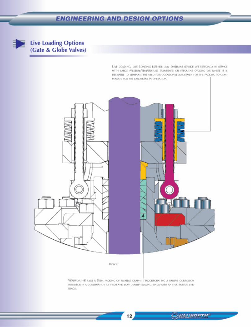
VIEW CPAGE 12
VIEW BPAGE 3
STANDARDS
FACE TO FACE / END TO END: ASME B16.10FLANGE DIMENSIONS: ASME B16.5BW DIMENSIONS: ASME B16.25DESIGN: API 600 ASME B16.34TESTING: API 598
A RISING STEM WITH A PRECISION ACME THREAD AND CLOSE
STRAIGHTNESS TOLERANCES EXTEND THE LIFE OF STEM AND
YOKE NUT.
THRUST BEARINGS MOUNTED YOKE NUT PROVIDES REDUCED
OPERATING TORQUE.
YOKE DESIGNED TO PERMIT READY ACCESS FOR MAINTENANCE
AND EASY ADAPTATION FOR ACTUATOR MOUNTING.
A BELLEVILLE SPRING WASHER IS USED TO MAINTAIN A SET
TORQUE ON THE PACKING GLAND NUT. AN OPTIONAL LIVE
LOADING PACKING SYSTEM IS AVAILABLE.
PACKING GLAND EYE BOLTS MOUNTED IN A TWO CLAMP
ATTACHED TO THE BONNET PERMITS A CONSTANT PACKING
LOAD INDEPENDENT OF BONNET MOVEMENT.
THE YOKE IS POSITIVELY SECURED TO THE BODY WITH STUDS
WHICH ALSO FACILITATES MAINTENANCE.
THE PRESSURE SEAL GASKET UTILIZES AN ANGULAR
RELATIONSHIP BETWEEN THE GASKET AND BODY SEALING
SURFACE TO ALLOW AN INCREASE IN SEALING FORCE WITH AN
INCREASE IN OPERATING PRESSURE.
A STAINLESS STEEL INLAY IN THE BODY SEALING AREA ASSURES
CORROSION RESISTANCE AND LONG WAR LIFE.
THE STELLITED BACK SEAT PROVIDES A LONG WEARING AND
DAMAGE RESISTANT SURFACE FOR RELIABLE SEALING.REPLACING STEM PACKING UNDER PRESSURE IS NOT
RECOMMENDED.
A STELLITE OVERLAY ON SEAT RINGS PROVIDES INCREASED
RESISTANCE TO WEAR. ABRASION AND EROSION OF THE
SEALING SURFACES. THE SEAT RINGS ARE SEAL WELDED TO
PROVIDE A PRESSURE TIGHT JOINT.
STREAMLINED INTERNAL BORE ALLOWS MAXIMUM FLOW
WITH A MINIMUM OF TURBULENCE.
THE FLEXIBLE WEDGE RESIST STICKING DUE TO TEMPERATURE
CHANGES AND PIPELINE LOADS. THE STELLITED FACED SEATING
SURFACES ARE GROUND AND LAPPED FOR TIGHT SEALING.

3
Pressure Seal ValvesOutside Screw and Yoke (OS&Y)
TRIMS
• THE WALWORTH® STANDARD TRIM IS API NO. 5 (HF) WHERE THE
SEALING SURFACE OF THE GATE AND THE SEAT SEALING SURFACE IS
OVERLAID WITH STELLITE NO. 6
• WALWORTH® CAN FURNISH VALVES WITH A VARIETY OF TRIMS AND
MATERIALS TO MEET THE CUSTOMERS REQUIREMENTS FOR AN OPTIMUM
SERVICE LIFE.
• ALL WALWORTH® PRESSURE SEAL VALVES ARE DESIGNED IN ACCOR-DANCE WITH API 600 STYLE A AND TESTED IN ACCORDANCE WITH
API 598. AS WELL AS TO SPECIAL CUSTOMER REQUIREMENTS.
KNOCK OUT HOLES FOR EASY REMOVAL OF
SEGMENTAL THRUST RINGS.
SEGMENTAL THRUST RINGS OF HARDENED
ALLOY STEEL FOR POSITIVE RETENTION OF
PRESSURE LOAD.
STAINLESS BODY INLAY PROVIDES A
CORROSION RESISTANT GASKET SEALING
SURFACE.
BONNET RETAINER INCORPORATES THE
RETAINER STUDS THAT ARE TIGHTENED TO
ESTABLISH THE INITIAL GASKET SEAL.
SPACER RING OF HARDENED ALLOY STEEL
PREVENTS DEFORMATION OF THE TOP OF
THE SOFT METALLIC GASKET
PRESSURE SEAL GASKET OF SOFT CARBON
STEEL IS SILVER PLATED TO PROVIDE CORRO-SION RESISTANCE AND PERFECT SEALING.
VIEW A
BODY A GUIDES PROVIDE A CLOSE TOLERANCE CONTROL OF THE
WEDGE TO MINIMIZE SEAT RUBBING WHEN CLOSING.
STEM TO WEDGE CONNECTION IS SELF ALIGNING TO PREVENT SIDE
LOADS.
VIEW B
ONE PIECE FLEXIBLE TYPE WEDGE WITH WELD DEPOSITED
STELLITE NO. 6 FACINGS. A FLEXIBLE WEDGE INSURES PRES-SURE TIGHTNESS. PREVENTS WEDGE FORM STICKING AND
REDUCES OPERATING TORQUE NEEDED TO OPEN VALVE. IT ALSO
OFFERS LESS RESISTANCE TO UNSEATING DUE TO TEMPERATURE
CHANGES.
HIGH PERFORMANCEPRESSURE-SEAL DESIGN
FLEXIBLE WEDGE

5
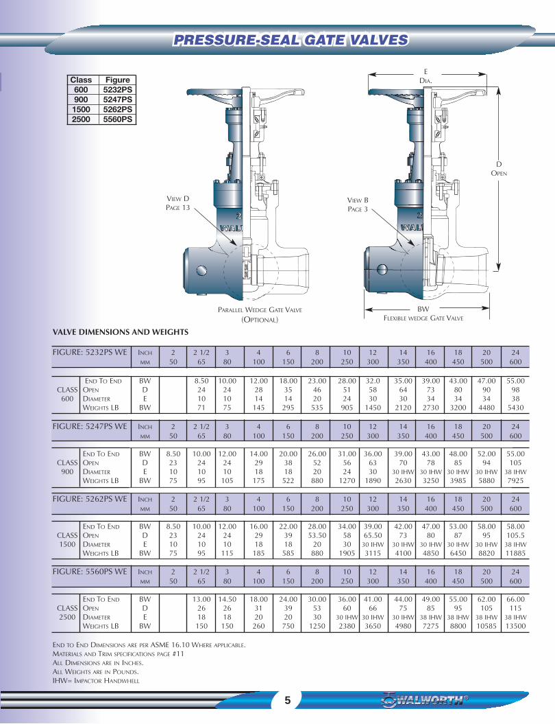
PRESSURE-SEAL GATE VALVESPRESSURE-SEAL GATE VALVES
Class Figure600 5232PS900 5247PS1500 5262PS2500 5560PS
END TO END DIMENSIONS ARE PER ASME 16.10 WHERE APPLICABLE.MATERIALS AND TRIM SPECIFICATIONS PAGE #11ALL DIMENSIONS ARE IN INCHES.ALL WEIGHTS ARE IN POUNDS.IHW= IMPACTOR HANDWHELL
VALVE DIMENSIONS AND WEIGHTS
FIGURE: 5232PS WE INCH 2 2 1/2 3 4 6 8 10 12 14 16 18 20 24MM 50 65 80 100 150 200 250 300 350 400 450 500 600
END TO END BW 8.50 10.00 12.00 18.00 23.00 28.00 32.0 35.00 39.00 43.00 47.00 55.00CLASS OPEN D 24 24 28 35 46 51 58 64 73 80 90 98
600 DIAMETER E 10 10 14 14 20 24 30 30 34 34 34 38WEIGHTS LB BW 71 75 145 295 535 905 1450 2120 2730 3200 4480 5430
FIGURE: 5247PS WE INCH 2 2 1/2 3 4 6 8 10 12 14 16 18 20 24MM 50 65 80 100 150 200 250 300 350 400 450 500 600
END TO END BW 8.50 10.00 12.00 14.00 20.00 26.00 31.00 36.00 39.00 43.00 48.00 52.00 55.00CLASS OPEN D 23 24 24 29 38 52 56 63 70 78 85 94 105
900 DIAMETER E 10 10 10 18 18 20 24 30 30 IHW 30 IHW 30 IHW 30 IHW 38 IHWWEIGHTS LB BW 75 95 105 175 522 880 1270 1890 2630 3250 3985 5880 7925
FIGURE: 5262PS WE INCH 2 2 1/2 3 4 6 8 10 12 14 16 18 20 24MM 50 65 80 100 150 200 250 300 350 400 450 500 600
END TO END BW 8.50 10.00 12.00 16.00 22.00 28.00 34.00 39.00 42.00 47.00 53.00 58.00 58.00CLASS OPEN D 23 24 24 29 39 53.50 58 65.50 73 80 87 95 105.51500 DIAMETER E 10 10 10 18 18 20 30 30 IHW 30 IHW 30 IHW 30 IHW 30 IHW 38 IHW
WEIGHTS LB BW 75 95 115 185 585 880 1905 3115 4100 4850 6450 8820 11885
FIGURE: 5560PS WE INCH 2 2 1/2 3 4 6 8 10 12 14 16 18 20 24MM 50 65 80 100 150 200 250 300 350 400 450 500 600
END TO END BW 13.00 14.50 18.00 24.00 30.00 36.00 41.00 44.00 49.00 55.00 62.00 66.00CLASS OPEN D 26 26 31 39 53 60 66 75 85 95 105 1152500 DIAMETER E 18 18 20 20 30 30 IHW 30 IHW 30 IHW 38 IHW 38 IHW 38 IHW 38 IHW
WEIGHTS LB BW 150 150 260 750 1250 2380 3650 4980 7275 8800 10585 13500
VIEW DPAGE 13
PARALLEL WEDGE GATE VALVE
(OPTIONAL)
EDIA.
DOPEN
VIEW BPAGE 3
BWFLEXIBLE WEDGE GATE VALVE

6
PRESSURE-SEAL GLOBE VALVESPRESSURE-SEAL GLOBE VALVES
Outside Screw and Yoke (OS&Y)Rising Stem, Swivel Plug Discand Removable Yoke Sleeve
1.- HANDWHELL: A197 OR ASTM A216 GR WCBSPOKE DESIGN PROVIDES MORE EFFICIENT TRANSFER OF LOAD
WITH MINIMUM WEIGHT.
4.- THRUST BEARINGS: ALLOY STEEL. FOR EASY OPER-ATION REDUCED TORQUE AND SUPPORT THRUST LOADS.
5.- GREASE FITTING: STEEL
6.- YOKE SLEEVE: A439 D2 OR B148 95600. IT IS
DESIGNED TO PERMIT REMOVAL FROM THE YOKE WHILE THE
VALVE IS IN SERVICE.
7.- YOKE: A216 GR WCB. THE TWO LARGE WINDOWS
ALLOW EASY ACCESS TO THE PACKING CHAMBER AND SIMPLIFIES
MAINTENANCE.
8.- SPRING LOADING: A BELLEVILLE SPRING WASHER
MAINTAINS INITIAL PACKING EYE BOLT TORQUE (LIVE LOADING
IS OPTIONAL).
9.- EYE BOLT CLAMP: A515 GR 70. THE TWO PIECE
CLAMP ALLOWS EASY ACCESS TO THE STEM PACKING AND MAIN-TAINS A FIXED LOAD ON THE STEM PACKING REGARDLESS OF
BONNET POSITION.
16.- BONNET RETAINER: A515 GR 70. THE INITIAL SEAL
OF THE PRESSURE SEAL GASKET IS ESTABLISHED BY TIGHTENING
THE RETAINER STUDS.
17.- PRESSURE SEAL GASKET: SOFT CARBON STEEL. THE
GASKET IS SILVER PLATED TO PROVIDE CORROSION RESISTANCE
AND A PERFECT SEAL. THE ANGULAR RELATIONSHIP OF THE
BONNET, GASKET AND BOY UTILIZES THE FORCE GENERATED BY
THE LINE PRESSURE TO INCREASE THE GASKET SEALING EFFECT.
18.- BONNET: A216 GR WCB OR SAME AS BODY IT PRO-VIDES A SEALING SURFACE FOR THE PRESSURE SEAL GASKET AND
INCORPORATES A HARD FACED BACK SEAT.
22.- SEAT RING: ALLOY STEEL. THEY ARE PART OF THE TRIM.THE STELLITED SEAT RING PROVIDE INCREASED RESISTANCE TO
WEAR, ABRASION AND EROSION OF THE SEALING SURFACE. IT IS
SEAL WELDED TO PROVIDE A TIGHT JOINT.
23.- DISC: CAST ALLOY STEEL. IT IS PART OF THE TRIM. THE
STELLITE FACED SEATING SURFACES ARE GROUND AND
LAPPED, TO ASSURE TIGHT SEALING.
2.- YOKE CAPE STUD: A193 AND A194 2H NUT. FACILITATE MAINTENANCE.
3.- YOKE CAP: A515 GR 70: ALLOWS EASY ACCESS TO
THE BEARING CHAMBER.
10.- EYE BOLTS: AISI 1045. FACILITATES REPACKING.
11.- GLAND PLATE: A 515 GR 70. A HEAVY GLAND
PLATE FOR EVEN LOAD DISTRIBUTION.
12.- PACKING BUSHING: STAINLESS STEEL. IT IS PART
OF THE TRIM.
13.- STEM PACKING: FLEXIBLE GRAPHITE DESIGNED FOR
OPTIMUM CONTROL OF FUGITIVE EMISSIONS LEAKAGE TO THE
ATMOSPHERE.
15.- YOKE STUDS: A193 B7 & 2H OR A913 B16 & A194 7. YOKE IS BOLTED TO BODY TO FACILITATE MAINTENANCE.
14.- BONNET RETAINER STUDS: A 193 B7 & 2H OR
A 193 B16 & A 194 7
19.- SEGMENTAL THRUST RING: HARDENED ALLOY STEEL
IT ABSORBS ALL THE THRUST APPLIED BY INTERNAL PRESSURE.
20.- SPACER RING: HARDENED ALLOY STEEL. IT PREVENTS
DEFORMATION OF THE TOP PORTION OF THE SOFT METALLIC GASKET.
STAINLESS INLAY. THE GASKET CONTACTS A CORROSION-RESISTANT STAINLESS STEEL INLAY IN THE ADJACENT BODY
AREA.
21.- STEM: STAINLESS STEEL, IT IS PART OF THE TRIM. NON-REVOLVING STEM IS PROVIDED WITH A PRECISION ACME TREAD AND CLOSE ROUNDNESS
AND STRAIGHTNESS TOLERANCES.
24.- BODY: A216 GR WCB OR AS SPECIFIED BY
CUSTOMER. THE BODY IS DESIGNED TO WITHSTAND HIGH
PRESSURES WITH MINIMUM PRESSURE DROP.

7
PRESSURE-SEAL GLOBE VALVESPRESSURE-SEAL GLOBE VALVES
Class Figure600 5295PS900 5301PS1500 5308PS2500 5563PS
VALVE DIMENSIONS AND WEIGHTS
FIGURE: 5295PS WE INCH 2 2 1/2 3 4 6 8 10 12 14 16 18 20 24MM 50 65 80 100 150 200 250 300 350 400 450 500 600
END TO END BW 8.50 10.00 12.00 18.00 23.00 28.00 32.0 35.00 39.00 43.00 47.00 55.00CLASS OPEN D 23 25 28 33.50 44 49 53 62 70 78 85 93
600 DIAMETER E 12 12 14 18 20 24 30 30 34 34 38 30 IHWWEIGHTS LB BW 71 75 135 285 520 885 1425 1780 2640 3100 4200 5200
FIGURE: 5301PS WE INCH 2 2 1/2 3 4 6 8 10 12 14 16 18 20 24MM 50 65 80 100 150 200 250 300 350 400 450 500 600
END TO END BW 8.50 10.00 12.00 14.00 20.00 26.00 31.00 36.00 39.00 43.00 48.00 52.00 55.00CLASS OPEN D 23 24 28 31 37 46 51 55 65 76 80 88 95
900 DIAMETER E 12 14 14 18 20 24 30 30 IHW 30 IHW 30 IHW 38 IHW 38 IHW 38 IHWWEIGHTS LB BW 70 95 105 160 430 850 1200 1850 2625 3130 3800 4600 6400
FIGURE: 5308PS WE INCH 2 2 1/2 3 4 6 8 10 12 14 16 18 20 24MM 50 65 80 100 150 200 250 300 350 400 450 500 600
END TO END BW 8.50 10.00 12.00 16.00 22.00 28.00 34.00 39.00 42.00 47.00 53.00 58.00 58.00CLASS OPEN D 23 24 28 31 37 47 52 58 65 76 80 88 951500 DIAMETER E 12 14 14 18 20 24 30 30 IHW 30 IHW 38 IHW 38 IHW 38 IHW 38 IHW
WEIGHTS LB BW 70 95 105 160 450 880 1750 2650 3800 4730 5800 7900 10200
FIGURE: 5563PS WE INCH 2 2 1/2 3 4 6 8 10 12 14 16 18 20 24MM 50 65 80 100 150 200 250 300 350 400 450 500 600
END TO END BW 11 13.00 14.50 18.00 24.00 30.00 36.00 41.00 44.00 49.00 55.00 58.00 58.00CLASS OPEN D 24 26 26 33 39 51 53 61 70 79 87 96 1052500 DIAMETER E 14 18 18 20 24 30 30 IHW 30 IHW 30 IHW 38 IHW 38 IHW 38 IHW 38 IHW
WEIGHTS LB BW 130 140 150 235 530 1150 1980 3140 4730 6650 7400 9800 12900
END TO END DIMENSIONS ARE PER ASME 16.10 WHERE APPLICABLE.MATERIALS AND TRIM SPECIFICATIONS PAGE #11ALL DIMENSIONS ARE IN INCHES.ALL WEIGHTS ARE IN POUNDS.IHW= IMPACTOR HANDWHELL
EDIA.
DOPEN
VIEW FPAGE 14
VIEW E
PAGE 14
BWGLOBE VALVE
STOP CHECK (NON-RETURN) VALVE
(OPTIONAL)

8
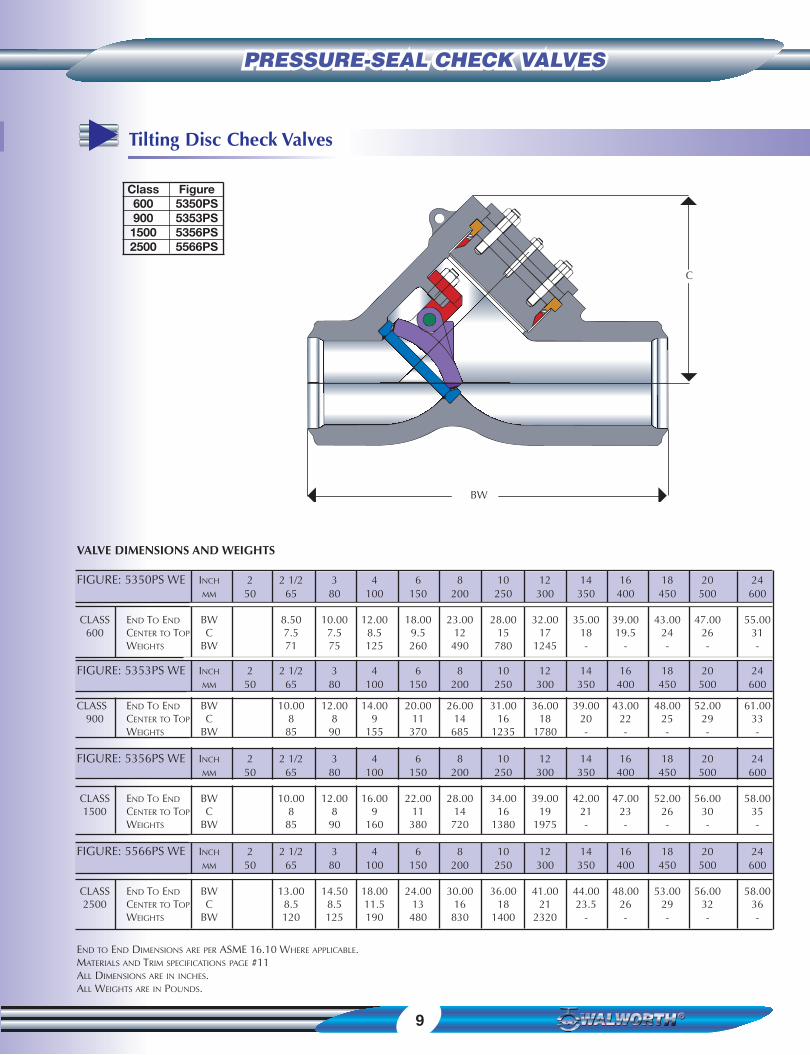
PRESSURE-SEAL CHECK VALVESPRESSURE-SEAL CHECK VALVES
Tilting DiscPressure Seal Check Valves
The Walworth® Pressure Seal tilting Disc Check Valves is designedto close quickly and quietly. It minimizes loud, damaging slammingand vibration noises caused when high velocity reverse flow isallowed to build up before the completion of closing.
CAUTION: INSTALL THIS VALVE IN A HORIZONTAL POSITION ONLY.CONTACT WALWORTH FOR OTHER INSTALLATION ORIENTATIONS.
14.- BONNET RETAINER STUDS: A193 B7 & 2H OR A193 B16 & A194 7
16.- BONNET RETAINER: A515 GR 10. THE INITIAL SEAL OF THE PRESSURE
SEAL GASKET IS ESTABLISHED BY
TIGHTENING THE RETAINER STUDS.
17.- PRESSURE SEAL GASKET: SOFT CARBON
STEEL. THE GASKET IS SILVER PLATED
TO PROVIDE CORROSION RESISTANCE
AND A PERFECT SEAL. THE ANGULAR
RELATIONSHIP OF THE BONNET
GASKET AND BOY UTILIZES THE FORCE
GENERATED BY THE LINE PRESSURE TO
INCREASE THE GASKET SEALING EFFECT.
18.- BONNET: A216 GR WCB OR SAME AS
THE BODY. IT PROVIDES A SEALING
SURFACE FOR THE PRESSURE SEAL
GASKET.
23.- DISC: CAST ALLOY STEEL. IT IS PART OF
THE TRIM. IT PROVIDES STELLITE FACED
SEATING SURFACES WHICH ARE
GROUND AN LAPPED, TO ASSURE
TIGHT SEALING.
22.- SEAT RING: ALLOY STEEL IT IS PART OF
THE TRIM. STELLITED SEAT RINGS
PROVIDE INCREASED RESISTANCE TO
WEAR, ABRASION AND EROSION OF
THE SEALING SURFACES, THEY ARE SEAL
WELDED TO PROVIDE A TIGHT JOINT.
19.- SEGMENTAL THRUST RING: HARDENED
ALLOY STEEL. IT ABSORBS ALL THE
THRUST APPLIED BY INTERNAL PRESSURE.
20.- SPACER RING: HARDENED ALLOY
STEEL. IT PREVENTS DEFORMATION
OF THE TOP PORTION OF THE SOFT
METALLIC GASKET.
24.- BODY: A216 GR WCB OR AS SPECIFIED
BY CUSTOMER. THE BODY IS DESIGNED
TO WITHSTAND HIGH PRESSURES WITH
MINIMUM PRESSURE DROP.
9
PRESSURE-SEAL CHECK VALVESPRESSURE-SEAL CHECK VALVES
Class Figure600 5350PS900 5353PS1500 5356PS2500 5566PS
Tilting Disc Check Valves
VALVE DIMENSIONS AND WEIGHTS
FIGURE: 5350PS WE INCH 2 2 1/2 3 4 6 8 10 12 14 16 18 20 24MM 50 65 80 100 150 200 250 300 350 400 450 500 600
CLASS END TO END BW 8.50 10.00 12.00 18.00 23.00 28.00 32.00 35.00 39.00 43.00 47.00 55.00600 CENTER TO TOP C 7.5 7.5 8.5 9.5 12 15 17 18 19.5 24 26 31
WEIGHTS BW 71 75 125 260 490 780 1245 - - - - -
FIGURE: 5353PS WE INCH 2 2 1/2 3 4 6 8 10 12 14 16 18 20 24MM 50 65 80 100 150 200 250 300 350 400 450 500 600
CLASS END TO END BW 10.00 12.00 14.00 20.00 26.00 31.00 36.00 39.00 43.00 48.00 52.00 61.00900 CENTER TO TOP C 8 8 9 11 14 16 18 20 22 25 29 33
WEIGHTS BW 85 90 155 370 685 1235 1780 - - - - -
FIGURE: 5356PS WE INCH 2 2 1/2 3 4 6 8 10 12 14 16 18 20 24MM 50 65 80 100 150 200 250 300 350 400 450 500 600
CLASS END TO END BW 10.00 12.00 16.00 22.00 28.00 34.00 39.00 42.00 47.00 52.00 56.00 58.001500 CENTER TO TOP C 8 8 9 11 14 16 19 21 23 26 30 35
WEIGHTS BW 85 90 160 380 720 1380 1975 - - - - -
FIGURE: 5566PS WE INCH 2 2 1/2 3 4 6 8 10 12 14 16 18 20 24MM 50 65 80 100 150 200 250 300 350 400 450 500 600
CLASS END TO END BW 13.00 14.50 18.00 24.00 30.00 36.00 41.00 44.00 48.00 53.00 56.00 58.002500 CENTER TO TOP C 8.5 8.5 11.5 13 16 18 21 23.5 26 29 32 36
WEIGHTS BW 120 125 190 480 830 1400 2320 - - - - -
END TO END DIMENSIONS ARE PER ASME 16.10 WHERE APPLICABLE.MATERIALS AND TRIM SPECIFICATIONS PAGE #11ALL DIMENSIONS ARE IN INCHES.ALL WEIGHTS ARE IN POUNDS.
C
BW


Terms and ConditionsAcceptance: All quotations for acceptance within 45 days from date ofquotation unless extended in writing. In the event a purchase order isplaced after this period of time, TWC The Valve Company reserves theright to re quote base prices of all valves offered. All orders and contractsare subject to credit approval and acceptance by The TWC The ValveCompany.
Freight: When prices are F.B.O. point of shipment- no freight allowance,Walworth will attempt to route shipments in the method which will resultin the lowest cost unless otherwise instructed. All shipments will be freightcharges collect except when stipulated on the purchase order in whichcase the buyer will be invoiced for all transportation charges.
Delivery of material to a common carrier shall be considered to be deliveryto Buyer and shall be at Buyer’s risk thereafter.
The Buyer shall file claims of loss of or damage to material in transitdirectly with the carrier.
Prices: There will be added to all prices quoted, any sales, use, occupation,excise or similar tax which Seller may be required to pay or collect in connection with the sale. Seller reserves the right to cancel any order in theevent that selling price(s) shall be established by Federal, State or other government regulation with respect to the product(s) covered by the orderwhich shall be lower than the price(s) specified in the order.
Escalation Terms: Price shown in the price schedule reflects the cost ineffect at the time of publication.
These prices will remain firm on all products with a quoted delivery oftwenty-six (26) weeks or less.
On products which have a schedule delivery of more than twenty-six (26)weeks the goods will be invoiced
Based on the applicable price sheet in effect at the time of shipment. Inno event will the invoiced price be less than the price originally quoted.
Purchased Components: (i.e. motors, gearing, etc.) Prices are quoted onsupplier price in effect at time of quotation. Actual invoice price may beadjusted in accordance with the supplier’s escalation policy.
Deferred Shipments: If for any reason the customer desires to delay shipments more than 30 days after manufacturing complete or to place ahold or stop to the order during the manufacturing cycle. TWC The ValveCompany reserves the right to consider the order cancelled and to invokecancellation charges per the schedule below.
Cancellation: After order acceptance by Walworth, items or completeorders may be cancelled and buyer will be charged for work performed,based on the following schedule:
Five (5%) percent of price of stock items.
Ten ( 10% ) percent of price of stock items ordered in quantities whichexceed normal inventory levels.
Five ( 5% ) percent of price prior to drawing submittal on made to orderitems.
Fifteen ( 15% ) percent drawing approval, but prior to the start of castings/Forgings
Thirty (30%) to Fifty (50%) percent during casting / Forging cycle, depend-ing on the state of completion.
Fifty-five (55%) to Seventy-five (75%) during machining and assemblyoperations, depending on the state of completion.
One hundred (100%) percent after final assembly and test.
Remittances: Remittances must be made to the address indicated on theinvoice.
Credit Terms: As quote. Invoices on balances overdue will be subject to aservice charge of One and a half (11/2 %) percent per month on suchindebtedness.
Deliveries: Shipments and deliveries shall at all times be subject to theapproval of Seller’s Credit Department. If the Buyer shall fall to make anypayments according to the terms of the contract, Seller may in addition toand not in limitation of its other rights and remedies, at its option, cancelall or any part of Buyer’s incomplete contracts with Seller or may defershipments or deliveries under Buyer’s contracts with Seller except uponreceipt of satisfactory security or for cash before shipment.
All schedules of shipment are estimated as closely as possible and Seller willuse its best efforts to ship within the time scheduled, but does not guaranteeto do so. Schedules commence with the date Seller receives authorization toproceed with the order, subject to the provisions of the next sentence. Theorder will not be released for manufacture until complete specifications andapproved drawings (if drawings approval is required) are received at theplant of manufacture and the estimated schedule of shipment will commence with the date of such receipt.
Seller shall not be liable for any direct, indirect or consequential damage orloss caused by any delay in delivery, regardless of the cause of delay. Withoutlimiting the generality of the foregoing, Seller assumes no responsibility fordelays in delivery resulting from fire, flood, accidents riots, strikes, transportation delays, labor or material shortages, existing or future laws, actsof any governmental authority, or any other cause beyond Seller’s control.Items offered from stock are subject to prior sale.
Inspection: Final inspection and acceptance of products must be made atthe plant facility, unless otherwise provided in the order and/or in agreedupon specifications. Prices do not include charges for special tests orinspections performed at the request of the Buyer, unless called for in theorder and/or in agree upon specifications.
Returns: Permission in writing and return tagging instructions must beobtained from Seller before any goods returned for credit or adjustment willbe accepted. Where returned goods are accepted, a minimum charge ofTwenty five percent (25%) of the invoice price will be made, plus freight fromboth directions and costs of reconditioning the material for resale as new.
Warranty: Seller will replace without charge or refund the purchase price ofproducts manufactured by Seller which prove to be defective in material orworkmanship, provided in each case that the product is properly installed andis used in the service for which the Seller recommends it and that writtenclaim, specifying the alleged defect, is presented to Seller within one yearfrom date of shipment. Seller shall in no event be responsible for (a) claimsfor labor, expenses or other damages occasioned by defective products or (b)for consequential or secondary damages. THE WARRANTY STATED IN THISPARAGRAPH IS IN LIEU OF ALL OTHER WARRANTIES EITHER EXPRESSEDOR IMPLIED. WITH RESPECT TO WARRANTIES THIS PARAGRAPH STATESBUYER’S EXCLUSIVE REMEDY AND SELLER’S EXCLUSIVE LIABILITY.
Design, etc.: Seller reserves the right to change design, materials or specifications without notice. There will be a charge for modifying anorder after it has been entered when such change or modification resultsin additional engineering or clerical work for either TWC The ValveCompany or our suppliers.
Minimum Charge: Orders totaling less that $100.00 (one hundred 00/100U.S. CY) net will be billed at a minimum charge of $50.00 (fifty 00/100U.S. CY)
Note: We reserve the right to correct obvious clerical errors in quotations,invoices and other contracts.

USA
4300 Campbell RoadSuite 100Houston, Tx. 77041Phone: (713) 996-9696Fax: (713) 996-9669
MEXICO
Av. de la Industria Lote 16Fracc. Industrial El TrébolC.P. 54600 TepotzotlánEdo. de MéxicoTel. (52) 55-5899-1700Fax: (52) 55-5899-1782e-mail: [email protected]
VALVES FOR INDUSTRY
SINCE 1842
PSV-05-4
www.walworthmx.com