mt3 / mt3 pro - data.dt-shop.com
TRANSCRIPT

MT3 / MT3 proNr. 1808 / 1809
21-6
616
230
5201
2 A
Ideas for dental technology

- 1 - EN
MT3 / MT3 pro1808 / 1809
ENGLISH
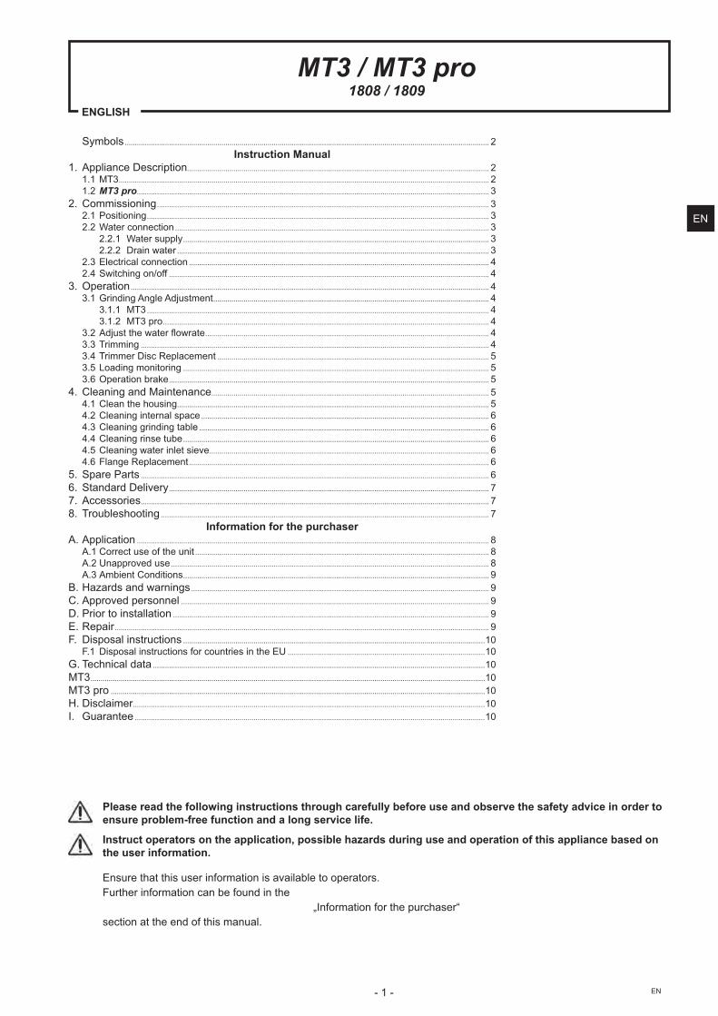
Symbols ..................................................................................................................................................................................... 2Instruction Manual
1. Appliance Description...................................................................................................................................................... 21.1 MT3 ........................................................................................................................................................................................ 21.2 MT3 pro ............................................................................................................................................................................... 3
2. Commissioning ..................................................................................................................................................................... 32.1 Positioning .......................................................................................................................................................................... 32.2 Water connection ............................................................................................................................................................ 3
2.2.1 Water supply ........................................................................................................................................................ 32.2.2 Drain water ........................................................................................................................................................... 3
2.3 Electrical connection ..................................................................................................................................................... 42.4 Switching on/off ............................................................................................................................................................... 4
��� ������ .................................................................................................................................................................................. 43.1 Grinding Angle Adjustment ......................................................................................................................................... 4
3.1.1 MT3 .......................................................................................................................................................................... 43.1.2 MT3 pro .................................................................................................................................................................. 4
���������������������� ............................................................................................................................................. 43.3 Trimming ............................................................................................................................................................................. 43.4 Trimmer Disc Replacement ....................................................................................................................................... 53.5 Loading monitoring ........................................................................................................................................................ 5���������� ����� ............................................................................................................................................................... 5
4. Cleaning and Maintenance.......................................................................................................................................... 54.1 Clean the housing ........................................................................................................................................................... 54.2 Cleaning internal space ............................................................................................................................................... 64.3 Cleaning grinding table ................................................................................................................................................ 64.4 Cleaning rinse tube ........................................................................................................................................................ 64.5 Cleaning water inlet sieve ........................................................................................................................................... 64.6 Flange Replacement ..................................................................................................................................................... 6
5. Spare Parts ............................................................................................................................................................................. 66. Standard Delivery ............................................................................................................................................................... 77. Accessories ............................................................................................................................................................................. 78. Troubleshooting ................................................................................................................................................................... 7
Information for the purchaserA. Application ............................................................................................................................................................................... 8
A.1 Correct use of the unit .................................................................................................................................................. 8A.2 Unapproved use .............................................................................................................................................................. 8A.3 Ambient Conditions ........................................................................................................................................................ 9
B. Hazards and warnings .................................................................................................................................................... 9C. Approved personnel ......................................................................................................................................................... 9D. Prior to installation ............................................................................................................................................................. 9E. Repair .......................................................................................................................................................................................... 9F. Disposal instructions ......................................................................................................................................................10
F.1 Disposal instructions for countries in the EU ..................................................................................................10G. Technical data .....................................................................................................................................................................10MT3 ....................................................................................................................................................................................................10MT3 pro ..........................................................................................................................................................................................10H. Disclaimer ...............................................................................................................................................................................10I. Guarantee ..............................................................................................................................................................................10
Please read the following instructions through carefully before use and observe the safety advice in order to ensure problem-free function and a long service life.
Instruct operators on the application, possible hazards during use and operation of this appliance based on the user information.
Ensure that this user information is available to operators.Further information can be found in the
„Information for the purchaser“ section at the end of this manual.
EN
- 2 -EN
Instruction Manual
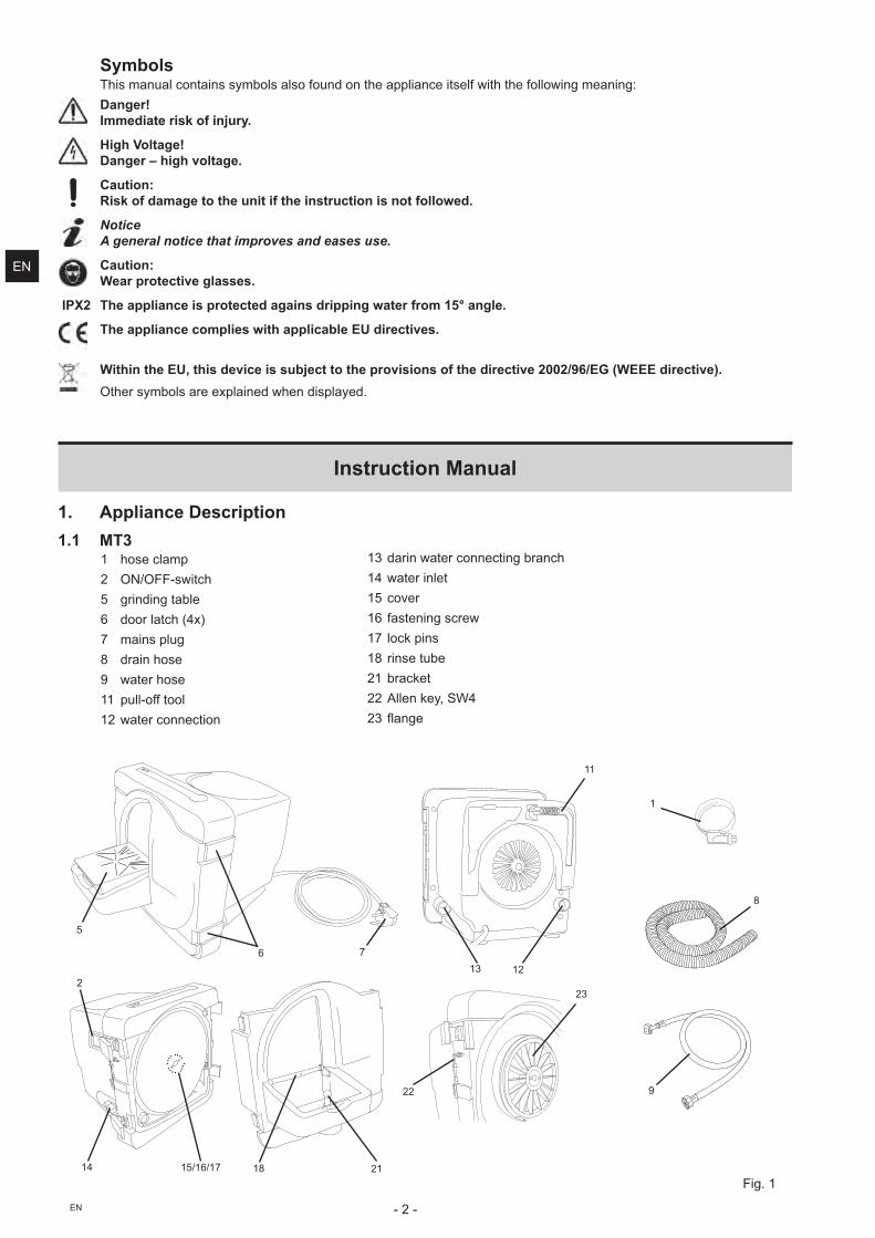
1. Appliance Description1.1 MT3
1 hose clamp�� ������������5 grinding table6 door latch (4x)7 mains plug8 drain hose9 water hose11 pull-off tool12 water connection
Symbols�����! �"��� � ���#!��"��"���$�� ��� ������"� ������"$��������$�""��� %�!� � %&
Danger! Immediate risk of injury.
High Voltage! Danger – high voltage.
Caution: Risk of damage to the unit if the instruction is not followed.
Notice A general notice that improves and eases use.
Caution: Wear protective glasses.
IPX2 The appliance is protected agains dripping water from 15° angle.
The appliance complies with applicable EU directives.
Within the EU, this device is subject to the provisions of the directive 2002/96/EG (WEEE directive).������#!��"������'�"� ������ �����"#���
13 darin water connecting branch14 water inlet15 cover16 fastening screw17 lock pins18 rinse tube21 bracket22 Allen key, SW4���� %�
5
6
2
7
8
9
11
1213
23
22
211815/16/1714
Fig. 1
1
EN
- 3 - EN
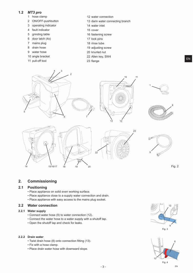
1.2 MT3 pro1 hose clamp�� �������������� 3 operating indicator4 fault indicator5 grinding table6 door latch (4x)7 mains plug8 drain hose9 water hose10 angle bracket11 pull-off tool
12 water connection13 darin water connecting branch14 water inlet15 cover16 fastening screw17 lock pins18 rinse tube19 adjusting screw20 knurled nut22 Allen key, SW4���� %�
Fig. 2
5
6
234
7
9
10 11
1213
23
22
19 201815/16/1714
8
1
2. Commissioning2.1 Positioning
*�Place appliance on solid even working surface.*�Place appliance close to a supply water connection and drain.*�Place appliance with easy access to the mains plug socket.
2.2 Water connection2.2.1 Water supply
*�Connect water hose (9) to water connection (12).*�Connect the water hose to a water supply with a shutoff tap.*���� ��������$$��� ��������$���"�����
Fig. 39
12
2.2.2 Drain water*��������� ������+:;�� ���� ���� �<� %�+=�;�*�Fix with a hose clamp.*�Place drain water hose with downward slope.
Fig. 4
8
13
EN
- 4 -EN
2.3 Electrical connection*�Ensure the mains supply and voltage marked on the nameplate is identical.*�Plug in at the mains.
2.4 Switching on/offMT3:>����������"� ���� � ���$$��#����� ��$$�������+�?���%��=;�MT3 pro:
If the operating screen is damaged or defect in any way, please remove the device from operation and send in for repair.>����������"� ���� � ���$$��#����� ��$$�������+�?���%���;�The blue LED (3, Fig. 2) remains illuminated when the appliance is in operation.
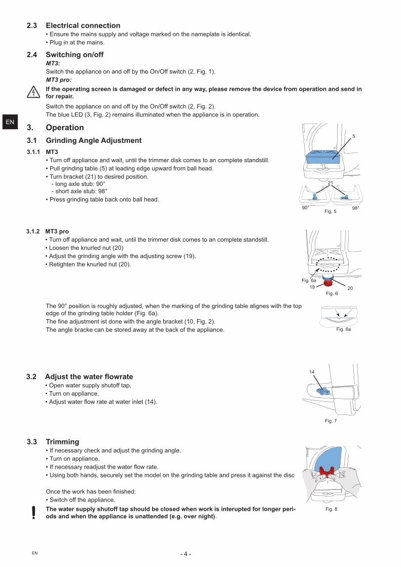
3. Operation3.1 Grinding Angle Adjustment3.1.1 MT3
*�Turn off appliance and wait, until the trimmer disk comes to an complete standstill.*�Pull grinding table (5) at leading edge upward from ball head.*�Turn bracket (21) to desired position.
- "� %�'"�����&�@JK - �����'"�����&�@:K
*�Press grinding table back onto ball head.@JK @:K
Fig. 5
21
5
3.1.2 MT3 pro*�Turn off appliance and wait, until the trimmer disk comes to an complete standstill.*�Loosen the knurled nut (20)*�Adjust the grinding angle with the adjusting screw (19).*�Retighten the knurled nut (20).
19 20Fig. 6
Fig. 6a
����@JK������� �������%�"#�������?���� ����!��� %��$����%�� �� %��"��"�% ������������� edge of the grinding table holder (Fig. 6a).����< ������!� ������ ��������� %"��������+=J?���%���;�The angle bracke can be stored away at the back of the appliance. Fig. 6a
3.2 ������������ ���� ��*���� ���������"#�����$$���*�Turn on appliance.*������������������������ "��+=O;�
14
Fig. 7
3.3 Trimming*�If necessary check and adjust the grinding angle.*�Turn on appliance.*�Q$� ������#����������������������*�Using both hands, securely set the model on the grinding table and press it against the disc
� ����������������� �< �����&*�Switch off the appliance.
The water supply shutoff tap should be closed when work is interupted for longer peri-ods and when the appliance is unattended (e.g. over night).
Fig. 8
EN
- 5 - EN
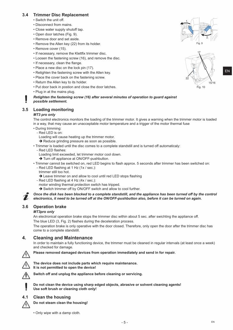
3.4 Trimmer Disc Replacement*�Switch the unit off.*�Disconnect from mains.*�Close water supply shutoff tap.*���� ������"�����+��%��@;�*�Remove door and set aside.*�Remove the Allen key (22) from its holder.*�Remove cover (15).*�Q$� ������#?���!�V�����X"�<'���!!��������*�Loosen the fastening screw (16), and remove the disc.*�Q$� ������#?��"� ����� %��*�Place a new disc on the lock pin (17).*�Retighten the fastening screw with the Allen key.*�Place the cover back on the fastening screw.*�Return the Allen key to its holder.*�Put door back in postion and close the door latches.*�Plug in at the mains plug.
Retighten the fastening screw (16) after several minutes of operation to guard against possible settlement.
3.5 Loading monitoringMT3 pro onlyThe control electronics monitors the loading of the trimmer motor. It gives a warning when the trimmer motor is loaded in a way, that may cause an unacceptable motor temperature and a trigger of the motor thermal fuse *�Y��� %���!!� %&
- Z���[\Y����� &Loading will cause heating up the trimmer motor.
�Reduce grinding pressure as soon as possible.*����!!������"������ �"�����������!��������!�"���� ���""� ������� ����$$���!��"#&
- Z���[\Y������&�Loading limit exceeded, let trimmer motor cool down.
� ��� ��$$���"� ������������������ �*����!!���� �������������� ?�����[\Y���%� ������������'��]����� ���$�����!!��������� ���������� &
- Z���[\Y����� %��=�^_�+='�������;&�trimmer still too hot.
� [�V����!!���� � ��""��������"�� �"�����[\Y���������� % - Z���[\Y����� %��O�^_�+O'�������;&�motor winding thermal protection switch has tripped.
�>�������!!����$$��#�������������� ��""��������"�$������ Once the disk has been blocked to a complete standstill, and the appliance has been turned off by the control
electronics, it need to be turned off at the ON/OFF-pushbutton also, before it can be turned on again.
3.6 Operation brakeMT3pro onlyAn electronical operation brake stops the trimmer disc within about 5 sec. after swichting the appliance off.�����"���[\Y�+�?���%���;����������� %��������"���� ���������The operation brake is only operative with the door closed. Therefore, only open the door after the trimmer disc has come to a complete standstill.
4. Cleaning and MaintenanceIn order to maintain a fully functioning device, the trimmer must be cleaned in regular intervals (at least once a week) and checked for damage.
Please removed damaged devices from operation immediately and send in for repair.
The device does not include parts which require maintenance. It is not permitted to open the device!
Switch off and unplug the appliance before cleaning or servicing.
Do not clean the device using sharp edged objects, abrasive or solvent cleaning agents! Use soft brush or cleaning cloth only!
4.1 Clean the housing Do not steam clean the housing!
*�� "#������������!���"���
Fig. 9
1.
2.
15/1622
17
Fig. 10
EN
- 6 -EN
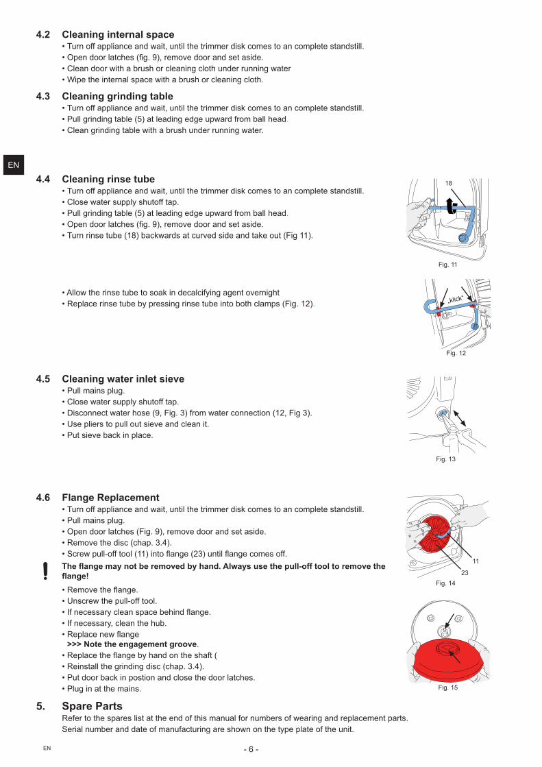
4.4 Cleaning rinse tube*�Turn off appliance and wait, until the trimmer disk comes to an complete standstill.*�Close water supply shutoff tap.*�Pull grinding table (5) at leading edge upward from ball head.*���� ������"�����+<%��@;?���!�V������� ����������*�Turn rinse tube (18) backwards at curved side and take out (Fig 11).
18
Fig. 11
*�Allow the rinse tube to soak in decalcifying agent overnight *�Replace rinse tube by pressing rinse tube into both clamps (Fig. 12). „klick“
Fig. 12
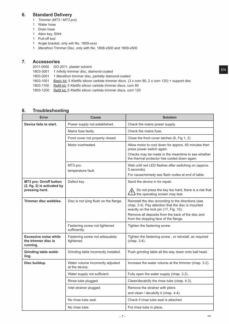
4.5 Cleaning water inlet sieve*�Pull mains plug.*�Close water supply shutoff tap.*�Disconnect water hose (9, Fig. 3) from water connection (12, Fig 3).*�Use pliers to pull out sieve and clean it.*�Put sieve back in place.
Fig. 13
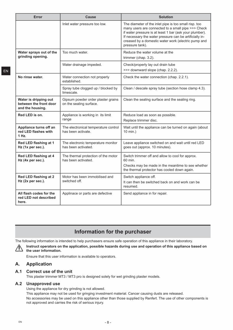
4.6 Flange Replacement*�Turn off appliance and wait, until the trimmer disk comes to an complete standstill.*�Pull mains plug.*���� ������"�����+��%��@;?���!�V������� ����������*�Remove the disc (chap. 3.4).*�>�������""��$$���"�+==;�� ��� %��+��;�� �"�� %����!����$$�
� ����������������� ������������������������������������������ �����������*�Z�!�V������ %��*�Unscrew the pull-off tool.*�Q$� ������#��"� ���������� ��� %��*�If necessary, clean the hub.*�Z��"��� ���� %�
>>> Note the engagement groove.*�Z��"������� %���#�� ��� ������$�+*�Reinstall the grinding disc (chap. 3.4).*�Put door back in postion and close the door latches.*�Plug in at the mains.
5. Spare PartsRefer to the spares list at the end of this manual for numbers of wearing and replacement parts. Serial number and date of manufacturing are shown on the type plate of the unit.
11
23Fig. 14
Fig. 15
4.2 Cleaning internal space*�Turn off appliance and wait, until the trimmer disk comes to an complete standstill.*���� ������"�����+<%��@;?���!�V������� ����������*�Clean door with a brush or cleaning cloth under running water*�Wipe the internal space with a brush or cleaning cloth.
4.3 Cleaning grinding table*�Turn off appliance and wait, until the trimmer disk comes to an complete standstill.*�Pull grinding table (5) at leading edge upward from ball head.*�Clean grinding table with a brush under running water.
EN
- 7 - EN
6. Standard Delivery1 ����������������� �1 Water hose1 Drain hose1 Allen key, SW41 Pull-off tool1 Angle bracket, only wih No. 1809-xxxx1 Marathon Trimmer Disc, only with No. 1808-x500 and 1809-x500
7. Accessories�J==�JJJJ� `���J==?��"������"V� 1803-3001 1 ������� trimmer disc, diamond-coated1803-2001 1 Marathon trimmer disc, partially diamond-coated1803-1001 q������& 5 ������� silicon carbide trimmer discs (3 x corn 80, 2 x corn 120) + support disc1803-1100 Z�<""���& 5 ������� silicon carbide trimmer discs, corn 801803-1200 Z�<""���&�5 ������� silicon carbide trimmer discs, corn 120
8. TroubleshootingError Cause Solution
Device fails to start. Power supply not established. Check the mains power supply.
Mains fuse faulty. Check the mains fuse.
Front cover not properly closed. Close the front cover latches (6, Fig 1, 2)
Motor overheated. Allow motor to cool down for approx. 60 minutes then press power switch again. Checks may be made in the meantime to see whether the thermal protector has cooled down again.
|������&�temperature fault
}��� �"�����[\Y�������$��������� %�� �+����'��5 seconds). �����������!��#����������������� ���$��"��
MT3 pro: On/off button ����"����#�$���%�$��������pressing hard.
Defect key Send the device in for repair.
Do not press the key too hard, there is a risk that the operating screen may tear.
Trimmer disc wobbles. Y������� ��"#� %������� ����� %�� Reinstall the disc according to the directions (see chap. 3.4). Pay attention that the disc is mounted exactly on the lock pin (17, Fig. 10).Remove all deposits from the back of the disc and $��!��������� %�$����$����� %��
Fastening screw not tightened ��$<��� "#�
Tighten the fastening screw.
Excessive noise while the trimmer disc is running.
Fastening screw not adequately tightened.
Tighten the fastening screw , or reinstall, as required (chap. 3.4).
Grinding table wobb-ling.
Grinding table incorrectly installed. Push grinding table all the way down onto ball head.
Disc buildup. Water volume incorrectly adjusted at the device.
Increase the water volume at the trimmer (chap. 3.2).
}�������"#� ����$<��� � Fully open the water supply (chap. 3.2).
Rinse tube plugged. Clean/decalcify the rinse tube (chap. 4.3).
Inlet strainer plugged Remove the strainer with pliersand clean / decalcify it (chap. 4.4).
No rinse tube seal. Check if rinse tube seal is attached.
No rinse tube. Put rinse tube in place.
EN
- 8 -EN
Error Cause Solution
Inlet water pressure too low. The diameter of the inlet pipe is too small risp. too many users are connected to a small pipe >>> Check if water pressure is at least 1 bar (ask your plumber). Q$� ������#������������������ ������<��""#�� -creased by a domestic water work (electric pump and pressure tank).
Water sprays out of the grinding opening.
Too much water. Reduce the water volume at thetrimmer (chap. 3.2).
Water drainage impeded. Check/properly lay out drain tube>>> downward slope (chap. 2.2.2).
No rinse water. Water connection not properly established.
Check the water connection (chap. 2.2.1).
Spray tube clogged up / blocked by limescale.
Clean / descale spray tube (section hose clamp 4.3).
Water is dripping out between the front door and the housing.
Gipsum powder order plaster grains on the sealing surface.
Clean the sealing surface and the sealing ring.
Red LED is on. Appliance is working in its limit range
Reduce load as soon as possible.Replace trimmer disc.
Appliance turns off an ��&'*�������$��1 Hz.
The electronical temperature control has been activate.
Wait until the appliance can be turned on again (about 10 min.)
+��&'*����$������;�Hz (1x per sec.).
The electronic temperature monitor has been activated.
Leave appliance switched on and wait until red LED goes out (approx. 10 minutes).
+��&'*����$������<�Hz (4x per sec.).
The thermal protection of the motor has been activated.
Switch trimmer off and allow to cool for approx. 60 min.Checks may be made in the meantime to see whether the thermal protector has cooled down again.
+��&'*����$��������Hz (2x per sec.).
Motor has been immobilised and switched off.
Switch appliance off. It can then be switched back on and work can be resumed.
��������%������ ���red LED not described here.
Applinace or parts are defective Send appliance in for repair.
Information for the purchaserThe following information is intended to help purchasers ensure safe operation of this appliance in their laboratory.
Instruct operators on the application, possible hazards during use and operation of this appliance based on the user information.Ensure that this user information is available to operators.
A. ApplicationA.1 Correct use of the unit
This plaster trimmer MT3 / MT3 pro is designed solely for wet grinding plaster models.
A.2 Unapproved useUsing the appliance for dry grinding is not allowed.This appliance may not be used for gringing investment material. Cancer causing dusts are released.No accessories may be used on this appliance other than those supplied by Renfert. The use of other components is not approved and carries the risk of serious injury.
EN
- 9 - EN
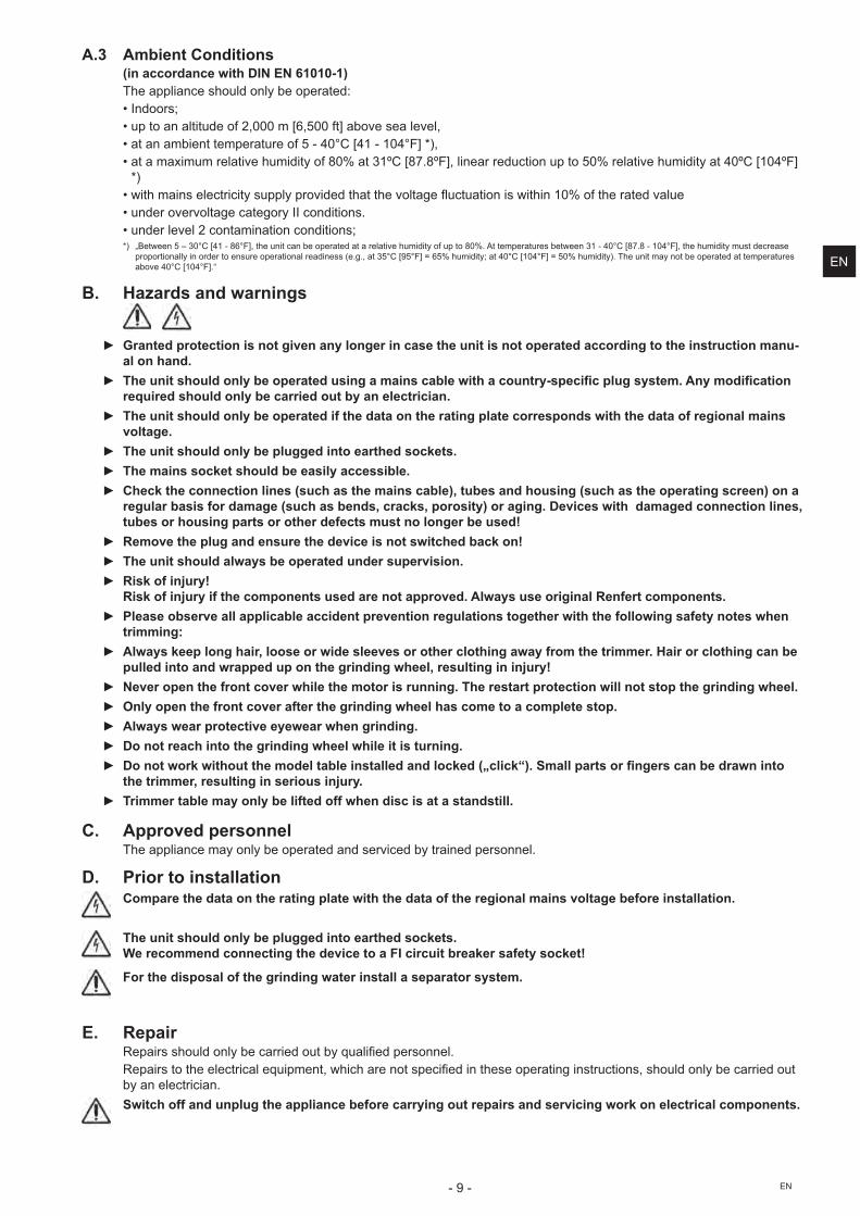
A.3 Ambient Conditions(in accordance with DIN EN 61010-1)������"� �������"��� "#����������&*�Indoors;*�up to an altitude of 2,000 m [6,500 ft] above sea level,*�� �!��� ��!��������$�]���OJK���O=���=JOK����;?*�at a maximum relative humidity of 80% at 31ºC [87.8ºF], linear reduction up to 50% relative humidity at 40ºC [104ºF]
*)*�����!� ���"������#�����"#����V����������V�"%�������� �������� �=J���$��������V"��*�under overvoltage category II conditions.*�under level 2 contamination conditions;�;� �q���� �]����JK���O=���:�K��?����� ��� ���������������"�V����!���#��$������:J������!������������� ��=���OJK���:��:���=JOK��?������!���#�!�����������
�������� ""#�� ���������� ����������� "����� ����+��%�?���]K���@]K������]����!���#���OJK���=JOK�����]J����!���#;������� ��!#� ��������������!����������V��OJK���=JOK����
B. Hazards and warnings
= Granted protection is not given any longer in case the unit is not operated according to the instruction manu-
al on hand. = ����$����������������� ������$�������$���%�����$����%���� ����%$"%��������������������$"%��$���
required should only be carried out by an electrician. = The unit should only be operated if the data on the rating plate corresponds with the data of regional mains
voltage. = The unit should only be plugged into earthed sockets. = The mains socket should be easily accessible. = Check the connection lines (such as the mains cable), tubes and housing (such as the operating screen) on a
regular basis for damage (such as bends, cracks, porosity) or aging. Devices with damaged connection lines, tubes or housing parts or other defects must no longer be used!
= Remove the plug and ensure the device is not switched back on! = The unit should always be operated under supervision. = Risk of injury!
Risk of injury if the components used are not approved. Always use original Renfert components. = Please observe all applicable accident prevention regulations together with the following safety notes when
trimming: = Always keep long hair, loose or wide sleeves or other clothing away from the trimmer. Hair or clothing can be
pulled into and wrapped up on the grinding wheel, resulting in injury! = Never open the front cover while the motor is running. The restart protection will not stop the grinding wheel. = Only open the front cover after the grinding wheel has come to a complete stop. = Always wear protective eyewear when grinding. = Do not reach into the grinding wheel while it is turning. = *�������� ?��$�����������������$��������������%?���@%�$%?J#��K������� ���� �"�� ��%������ ����$����
the trimmer, resulting in serious injury. = Trimmer table may only be lifted off when disc is at a standstill.
C. Approved personnelThe appliance may only be operated and serviced by trained personnel.
D. Prior to installation Compare the data on the rating plate with the data of the regional mains voltage before installation.
The unit should only be plugged into earthed sockets. We recommend connecting the device to a FI circuit breaker safety socket!
For the disposal of the grinding water install a separator system.
E. RepairZ����������"��� "#���������������#���"�<�������� �"�Z������������"�����"������!� ?���������� �������<���� ����������� %�� ������ �?�����"��� "#��������������by an electrician.
Switch off and unplug the appliance before carrying out repairs and servicing work on electrical components.
EN
- 10 -EN
F. Disposal instructions����� ������"���������������$��#�������"���<�!�����������"���<�!�����"������ $��!����$� #��_��������������� �the unit.
F.1 Disposal instructions for countries in the EUTo conserve and protect the environment, prevent environmental pollution and improve the recycling of raw materials, the European Commission adopted a directive that requires the manufacturer to accept the return of electrical and electronic units for proper disposal or recycling.
Within the European Union units with this symbol should not therefore be disposed of in unsorted domestic waste.For more information regarding proper disposal please apply at your local authorities.
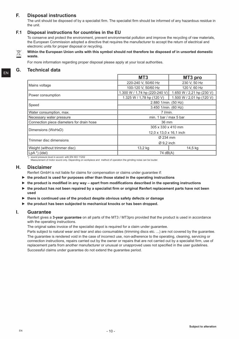
G. Technical dataMT3 MT3 pro
Mains voltage220-240 V, 50/60 Hz 230 V, 50 Hz100-120 V, 50/60 Hz 120 V, 60 Hz
Power consumption1.300 W / 1,74 hp (220-240 V) 1.650 W / 2,21 hp (230 V)
1.325 W / 1,78 hp (120 V) 1.500 W / 2,01 hp (120 V)
Speed2.880 1/min. (50 Hz) 3.450 1/min. (60 Hz)
Water consumption, max. 7 l/min.Necessary water pressure min. 1 bar / max 5 barConnection piece diameters for drain hose 36 mm
Dimensions (WxHxD)305 x 330 x 410 mm
12,0 x 13,0 x 16,1 inch
Trimmer disc dimensionsØ 234 mmØ 9,2 inch
Weight (without trimmer disc) 13,2 kg 14,5 kgLpA *) (idel) 74 dB(A)
�;� ��� �����������"�V�"�� ������������\��Q>��==�J� Maesurement of motor sound only. Depending on workpiece and method of operation the grinding noise can be louder.
H. DisclaimerZ� $���`!�^���� ��"��"��$����"�!��$�����!�� ��� �����"�!��� ����%�� ����$&
= the product is used for purposes other than those stated in the operating instructions = ��� ���%��$�����$"��$����������Q���� ��� ������$"%��$������% $���$������ ��$���$��� �%�$���� = ��� ���%������������ ��$ ���������%$��$���" ��� �� $�$����+�� �� ���%������ �������������
used = there is continued use of the product despite obvious safety defects or damage = the product has been subjected to mechanical knocks or has been dropped.
I. GuaranteeRenfert gives a 3-year guarantee on all parts of the MT3 / MT3pro provided that the product is used in accordance with the operating instructions. The original sales invoice of the specialist depot is required for a claim under guarantee. Parts subject to natural wear and tear and also consumables (trimming discs etc. ...) are not covered by the guarantee.The guarantee is rendered void in the case of incorrect use, non-adherence to the operating, cleaning, servicing or �� ���� �� ������ �?�������������������#������ ������������������ �������������#�������"���<�!?������$����"��!� �����$��!� �����! �$���������� ���"����� ����V�������� �������<���� ���������%����"� ���Successful claims under guarantee do not extend the guarantee period.
Subject to alteration
EN