mtl - fisco intrinsically safe fieldbus systems.pdf
TRANSCRIPT

7/27/2019 MTL - FISCO Intrinsically Safe Fieldbus Systems.pdf
http://slidepdf.com/reader/full/mtl-fisco-intrinsically-safe-fieldbus-systemspdf 1/24
Application Note
AN9026
FISCO Intrinsically Safe Fieldbus Systems
AN9026

7/27/2019 MTL - FISCO Intrinsically Safe Fieldbus Systems.pdf
http://slidepdf.com/reader/full/mtl-fisco-intrinsically-safe-fieldbus-systemspdf 2/24

7/27/2019 MTL - FISCO Intrinsically Safe Fieldbus Systems.pdf
http://slidepdf.com/reader/full/mtl-fisco-intrinsically-safe-fieldbus-systemspdf 3/24
i
Contents AN9026-3 Nov 2005
1 INTRODUCTION............................ ................................................................ ......................................................... ... 1 1.1 About this document.................................................................................................................................................................1 1.2 Background .................... ...................... ...................... ...................... ...................... ...................... ..................... ..................... ...1 1.3 Principle.....................................................................................................................................................................................1 1.4 Cables.........................................................................................................................................................................................1 1.5 Power supplies...........................................................................................................................................................................1 1.6 Field devices ..................... ...................... ...................... ..................... ...................... ..................... ..................... ..................... ...2 1.7 Documentation and inspection.................................................................................................................................................2 1.8 Conclusion ..................... ...................... ...................... ...................... ...................... ................... ..................... ...................... ......2
2 POWER SUPPLIES..................................................................... ................................................................... ............. 2 2.1 Introduction ..............................................................................................................................................................................2 2.2 Intrinsically safe output............................................................................................................................................................3 2.3 Host port....................................................................................................................................................................................3 2.4 24V supply ...................... ..................... ...................... ..................... ..................... ..................... ..................... ...................... ......4 2.5 Screen terminals........................................................................................................................................................................4 2.6 Status indicators........................................................................................................................................................................4
3 CONNECTING FIELD DEVICES TO A FISCO SUPPLY ........................................................ ............................ 4 3.1 Introduction ..............................................................................................................................................................................4 3.2 Output voltage and current......................................................................................................................................................4 3.3 Cable resistance ........................................................................................................................................................................5 3.4 Field device, voltage and current.............................................................................................................................................5 3.5 Typical calculation for IIC (9121-IS) power supply ..............................................................................................................6 3.6 Typical calculation for a IIB (9122-IS) power supply............................................................................................................6 3.7 Connecting “Entity certified” field devices.............................................................................................................................7 3.8 Connecting Zone 0 field devices...............................................................................................................................................8 3.9 Configuration tool.....................................................................................................................................................................8
4 COMMISSIONING AND FAULT FINDING................................ ................................................................ ........... 8 4.1 Introduction ..............................................................................................................................................................................8 4.2 Facilities.....................................................................................................................................................................................8 4.3 Resistance checks on cable ................... ...................... ...................... ...................... .................... ...................... ..................... ...9 4.4 Specialist test equipment.................... ..................... ...................... ..................... ..................... ..................... ...................... ......9 4.5 Procedure ..................................................................................................................................................................................9
5 CABLES AND ACCESSORIES.............................................................. ............................................................... .. 11 5.1 Cables.......................................................................................................................................................................................11 5.2 Terminators.............................................................................................................................................................................11 5.3 Interconnection blocks and enclosures..................................................................................................................................11
6 SURGE PROTECTION ....................................................... ................................................................ ..................... 12 6.1 Introduction ............................................................................................................................................................................12 6.2 Compatible surge protection devices.....................................................................................................................................13 6.3 Protecting the system..............................................................................................................................................................13
7 MOUNTING OF FISCO POWER SUPPLIES IN ZONE 2 AND DIVISION 2 .................................................. 15 7.1 General ....................................................................................................................................................................................15 7.2 Typical installation .................................................................................................................................................................15 7.3 Mounting of the units in Zone 2 or Division 2....................... ...................... ....................... ..................... ....................... ......15 7.4
Maintenance and fault finding...............................................................................................................................................16
7.5 Further combinations.............................................................................................................................................................16
7/27/2019 MTL - FISCO Intrinsically Safe Fieldbus Systems.pdf
http://slidepdf.com/reader/full/mtl-fisco-intrinsically-safe-fieldbus-systemspdf 4/24
ii
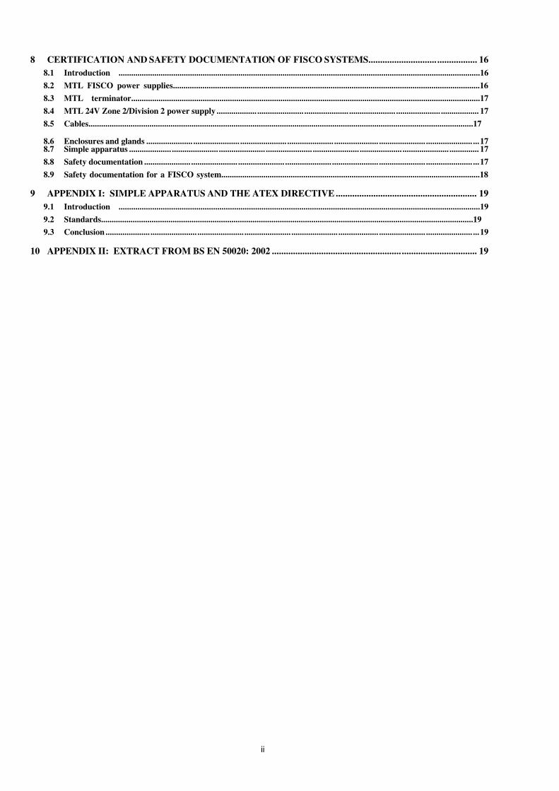
8 CERTIFICATION AND SAFETY DOCUMENTATION OF FISCO SYSTEMS............................. ................. 16 8.1 Introduction ............................................................................................................................................................................16 8.2 MTL FISCO power supplies..................................................................................................................................................16 8.3 MTL terminator......................................................................................................................................................................17 8.4 MTL 24V Zone 2/Division 2 power supply ................... ...................... ..................... ...................... ..................... .................. 17 8.5 Cables.......................................................................................................................................................................................17 8.6 Enclosures and glands ...................... ...................... ...................... ...................... ..................... ...................... ...................... ...17 8.7 Simple apparatus .................... ...................... ...................... ...................... ...................... .................... ...................... .............. 17 8.8 Safety documentation ...................... ...................... ...................... ...................... ...................... ...................... ...................... ...17 8.9 Safety documentation for a FISCO system...........................................................................................................................18
9 APPENDIX I: SIMPLE APPARATUS AND THE ATEX DIRECTIVE ............................................................ 19 9.1 Introduction ............................................................................................................................................................................19 9.2 Standards.................................................................................................................................................................................19 9.3 Conclusion ..................... ...................... ...................... ...................... ...................... ................... ...................... ...................... ...19
10 APPENDIX II: EXTRACT FROM BS EN 50020: 2002 ....................................................... ................................ 19

7/27/2019 MTL - FISCO Intrinsically Safe Fieldbus Systems.pdf
http://slidepdf.com/reader/full/mtl-fisco-intrinsically-safe-fieldbus-systemspdf 5/24
1
1 INTRODUCTION
1.1 About this document
This application note is a practical guide to the selection, installationand maintenance of equipment complying with the FieldbusIntrinsically Safe Concept (FISCO). The document begins with adiscussion of the origins of FISCO and an introduction to the mainelements that should be considered when assembling FISCOsystems. Later sections then develop each subject in more detail,
with the intention of providing clear guidance to new andexperienced fieldbus users.
The document will be updated regularly to reflect changes in practiceand to incorporate new information as it emerges. Please make sureyou have the most recent version by visiting the MTL websitewww.mtl-fieldbus.com or contacting your local MTLrepresentative. (The issue number of this application note is shownon the top right-hand corner of the Contents page.) MTL welcomescomments and constructive criticism of the text, which should bedirected by email to AN9026comments@mtl -inst .com
The commonly used term ‘H1’ is used in the text to describe the lowfrequency fieldbus (31.25kbits/s) as defined by FOUNDATION fieldbus™.
IEC terminology is used throughout the document when referring to
Gas and Apparatus Groups. North American equivalents are asfollows:
IEC North America
IIC (Hydrogen) Groups A, B
IIB (Ethylene) Group C
Table 1 - Gas group comparison
1.2 Background
The increase in the use of fieldbus systems in hazardous areas wasgiven a significant boost by the development of an international (IEC)standard for intrinsically safe (IS) fieldbus systems. This standard wasbased on experimental evidence and theoretical analysis done by the
German certification body PTB, and became known as the FieldbusIntrinsically Safe COncept (FISCO). The first edition of the fullstandard (IEC 60079-27) was published in April 2005.
The document is the first significant attempt to simplify theapplication and documentation requirements of IS systems in thelast fifty years. All the standards for explosion protection havebecome steadily more restrictive and more complex with time, andthe FISCO standard is a refreshing departure from this trend.
1.3 Principle
PTB in collaboration with German industry examined the intrinsicallysafe needs of the 31,25 kbit/s physical layer of fieldbus and developedan approach applicable to both Profibus-PA and FOUNDATION fieldbus™ H1 systems. A PTB report W-53e dated August 1994provided details of the experimental evidence and the initial thinkingon which an IEC document was based. From this proposal, the IECstandard has emerged with only very minor modifications. The resultis a comprehensive document, which covers all aspects of a lowfrequency fieldbus system allowing a system to be built with onlyminimum analysis of the safety requirements and very simpledocumentation. The design/manufacture of the apparatus was madeslightly more difficult so that the system configuration could be madeeasier. Arguably this has tended to improve safety as the apparatus iscertified, with the manufacturer subjected to surveillance, while systemdesign and installation is less tightly controlled.
The initial IS fieldbus proposal was restricted to ‘ia’ IIC sources of power, while the FISCO specification permits power supplies to usenon-linear regulation and the lower apparatus (gas) group IIB. Thismakes considerably more power available to the IS trunk andconsequently enables more field devices to be supported on each
IS trunk.
1.4 Cables
One of the more interesting results of the experimental work wasthat adding standard instrument cable to a power supply reduces the incendivity of the system rather than increasing it. Previously itwas assumed that the cable inductance and/or capacitance storedenergy would be available to supplement the energy available fromthe source of power. The experimental evidence however suggeststhat the cable parameters, because of their distributed nature,modify the form of the test apparatus spark so as to make it less
incendive and there is also some theoretical analysis to support thisview.
However because the experimental work covers only a limitedrange of cable parameters, circuit voltage and current, it wasconsidered prudent to limit the acceptable cable parameters in aFISCO IS circuit to those in Table 2.
Parameter Value
Loop resistance 15Ω/km to 150Ω/km
Loop inductance 0,4mH/km to 1mH/km
Capacitance 45nF/km to 200nF/km
Maximum length of each spur cable
60m in IIC and IIB
Maximum total cable length 1km in IIC and 5km in IIBTable 2 - FISCO cable parameters
These limits are not restrictive, as a typical fieldbus trunk cable hasparameters of 50Ω/km, 0,8mH/km and 120nF/km. The length of thetrunk is usually determined by the operational requirements. Therestriction of the length of the spurs can occasionally be irritating butif necessary this can be ameliorated by the use of additional currentlimitation.
In the longer term this work on cables may be applied to the designof all IS systems. This would require further work to determine thelimits that are applicable, and consequently for the time being therelaxation is only being applied to fieldbus systems.
1.5 Power supp lies
The FISCO standard utilises recent work on the ignition capability of constant current power supplies to propose acceptable levels of power for supplies with a ‘rectangular’ characteristic, as opposed to those witha falling, resistor-limited characteristic. This permits a greater useablepower for the fieldbus trunk, particularly if the less sensitive gas groupIIB (Ethylene) meets the installation requirements.
300
16
x
x
x
Safety
Operational
OUTPUT VOLTAGE (V)
x
Figure 1 - Current versus voltage curves for f ieldbus power su pplies
The use of active current limitation restricts the categorisation to ‘ib’, but itis not usual for a fieldbus trunk to be installed in a Zone 0. Any spur which is directly associated with a Zone 0 can be further protectedto achieve ‘ia’ status. The original Foundation Fieldbus requirementwas for a ‘IIC ia’ power supply, which was very restrictive, asindicated by the curves for the MTL5053 in Figure 1.
The available power is always considerably less than that of thesafety description and Figure 1 illustrates the available power achieved by the MTL FISCO power supplies. The calculation of howmany field devices can be powered from a power supply is arelatively simple application of Ohm’s Law. The user takes into

7/27/2019 MTL - FISCO Intrinsically Safe Fieldbus Systems.pdf
http://slidepdf.com/reader/full/mtl-fisco-intrinsically-safe-fieldbus-systemspdf 6/24
2
account the current consumption of each field device, the voltagedrop in the trunk cable, and the fact that field devices require 9V tooperate. If the assumption is made that the field devices require20mA and are all at the remote end of the IS trunk, then the number of devices which can be powered from the MTL IIC power supply isfive at the end of a 600m trunk. The corresponding IIB power supplywill supply twelve devices at the end of a 300m trunk,demonstrating the desirability of a IIB gas classification where thatis acceptable. The number of devices connected to a bus is alsodetermined by the plant layout, and by consideration of the system
reliability. The number of devices is usually quite low, five or six,with ten being unusual. If the available trunk length is a limitation,moving the repeater power supply into the field, (which may be aZone 2 or Division 2) may provide a solution.
A typical power supply is as illustrated in Figure 2. This power supply incorporates isolation from its source of power and the hostbus, the necessary terminator, and some diagnostic capability.These are not FISCO requirements but are operationally desirable.
IS Fieldbus
Power In19.2V to 30V
Host Fieldbus
Host Power 14 to 32 Vdc
30mA
SAFE AREA / ZONE 2 / DIV 2ZONE 1 / DIV 1
T
+ S _
7 8 9
+ + _
1 2 3+ _
4 5 6
S
T
Figure 2 - FISCO power supply
Refer to Section 2 for a more detailed discussion of power suppliesfor FISCO.
1.6 Field devices
The specification of the fieldbus field devices is determined by therequirement to be compatible with the power supplies and also thatadditional devices can be added to a system without having toreconsider the system safety. All devices have to be certified IICand have input parameters of voltage [Ui] 17,5V, current [Ii] 380mA,
power [Pi] 5,32W, capacitance [Ci] 5nF and inductance [Li] 10µH.Devices may have any temperature classification but the majoritywill be T4 (135oC).
The 5,32W dissipation usually requires some form of power limitation in each device so as to achieve a T4 temperature
classification but there are fairly standard methods of doing thiswithout much difficulty. It is possible to utilise devices certified tothe original fieldbus specification by introducing some power limitation in the spur. This does however require a smallmodification to the supporting documentation.
1.7 Documentation and inspection
A major benefit of the FISCO system is that no detailed analysis isnecessary to ensure the safety of the system, and additions do not
require a revaluation of the whole system. The gas group of thesystem is determined by the power supply, and the temperatureclassification of each piece of apparatus by its certification (usuallyT4).
The documentation is only a list of the connected apparatus. This isnormally done electronically and can readily cross-refer to thecertification documents of the apparatus.
A further advantage of this system is that inspection procedure issimplified to ensuring that the system is unchanged andundamaged. Many of the field devices carry a unique identifier andpart of the inspection procedure can be done automatically as partof the ‘asset management’ program. An occasional inspection for mechanical damage is still necessary, but if the equipment isunchanged and operational it is unlikely to be unsafe.
Documentation requirements of FISCO systems are described inmore detail in Section 8.
1.8 Conclusion
When a full range of FISCO devices are available it will be possibleto assemble a system without a detailed analysis anddocumentation, confident in the knowledge that it will be safe. It willbe simpler and possibly safer than the equivalent conventionalsystem.
The use of non-linear power supplies enables sufficient fielddevices to be connected to a single trunk, particularly if a IIB gasclassification is acceptable.
The FISCO technical specification is the first simplification of explosion protection standards since the rationalisation of the gas
grouping. “For these small mercies, much thanks”.
2 POWER SUPPLIES
2.1 Introduction
MTL’s FISCO power supplies are designed to meet therequirements of the International Electrotechnical Commission (IEC)technical specification IEC 60079-27 and provide power and thesignal repeater function for an intrinsically safe bus designed inaccordance with that specification.
The basic functions of the power supply are illustrated by Figure 3,which also shows a common but simple application. The power supply is shown mounted in a safe area. It may be mounted in a
Zone 2 or Division 2 location, as discussed in Section 7 of thisapplication note.
7/27/2019 MTL - FISCO Intrinsically Safe Fieldbus Systems.pdf
http://slidepdf.com/reader/full/mtl-fisco-intrinsically-safe-fieldbus-systemspdf 7/24
3
ZONE 1 / DIV 1
Host Power 14 to 32 Vdc
30mA
FISCOPOWERSUPPLY
SAFE AREA
24Vsupply
5 devices (110mA) in IIC
12 devices (250mA) in IIB
ISTRUNK
T
T
+ S _
7 8 9
+ + _ 1 2 3 + _
4 5 6S
May containpower source
andterminator
HOST
T
HOSTTRUNK
L
N
E
T
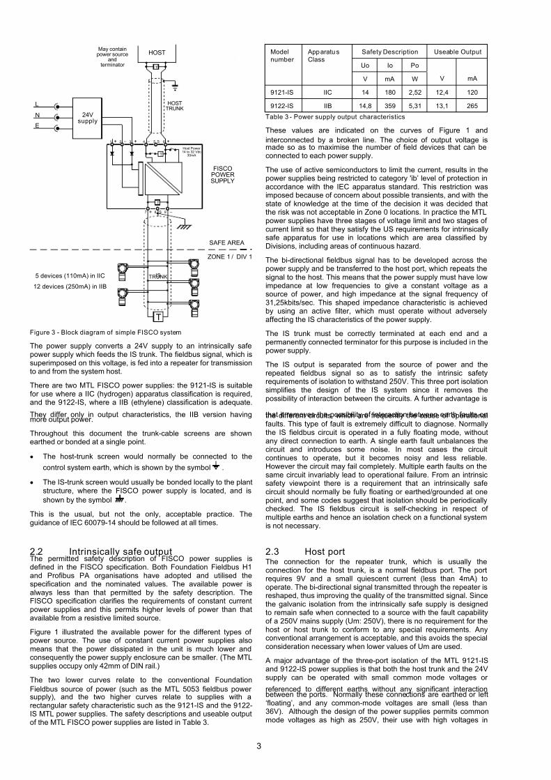
Figure 3 - Block diagram of simple FISCO system
The power supply converts a 24V supply to an intrinsically safepower supply which feeds the IS trunk. The fieldbus signal, which issuperimposed on this voltage, is fed into a repeater for transmissionto and from the system host.
There are two MTL FISCO power supplies: the 9121-IS is suitablefor use where a IIC (hydrogen) apparatus classification is required,and the 9122-IS, where a IIB (ethylene) classification is adequate.
They differ only in output characteristics, the IIB version havingmore output power.
Throughout this document the trunk-cable screens are shownearthed or bonded at a single point.
• The host-trunk screen would normally be connected to the
control system earth, which is shown by the symbol .
• The IS-trunk screen would usually be bonded locally to the plantstructure, where the FISCO power supply is located, and isshown by the symbol .
This is the usual, but not the only, acceptable practice. Theguidance of IEC 60079-14 should be followed at all times.
2.2 Intrinsically safe outputThe permitted safety description of FISCO power supplies isdefined in the FISCO specification. Both Foundation Fieldbus H1and Profibus PA organisations have adopted and utilised thespecification and the nominated values. The available power isalways less than that permitted by the safety description. TheFISCO specification clarifies the requirements of constant currentpower supplies and this permits higher levels of power than thatavailable from a resistive limited source.
Figure 1 illustrated the available power for the different types of power source. The use of constant current power supplies alsomeans that the power dissipated in the unit is much lower andconsequently the power supply enclosure can be smaller. (The MTLsupplies occupy only 42mm of DIN rail.)
The two lower curves relate to the conventional FoundationFieldbus source of power (such as the MTL 5053 fieldbus power supply), and the two higher curves relate to supplies with arectangular safety characteristic such as the 9121-IS and the 9122-IS MTL power supplies. The safety descriptions and useable outputof the MTL FISCO power supplies are listed in Table 3.
Safety Description Useable Output
Uo Io Po
Model
number
Apparatu s
Class
V mA W V mA
9121-IS IIC 14 180 2,52 12,4 120
9122-IS IIB 14,8 359 5,31 13,1 265
Table 3 - Power supply output characteristics
These values are indicated on the curves of Figure 1 andinterconnected by a broken line. The choice of output voltage ismade so as to maximise the number of field devices that can beconnected to each power supply.
The use of active semiconductors to limit the current, results in thepower supplies being restricted to category 'ib’ level of protection inaccordance with the IEC apparatus standard. This restriction wasimposed because of concern about possible transients, and with thestate of knowledge at the time of the decision it was decided thatthe risk was not acceptable in Zone 0 locations. In practice the MTLpower supplies have three stages of voltage limit and two stages of current limit so that they satisfy the US requirements for intrinsicallysafe apparatus for use in locations which are area classified byDivisions, including areas of continuous hazard.
The bi-directional fieldbus signal has to be developed across thepower supply and be transferred to the host port, which repeats thesignal to the host. This means that the power supply must have lowimpedance at low frequencies to give a constant voltage as asource of power, and high impedance at the signal frequency of 31,25kbits/sec. This shaped impedance characteristic is achievedby using an active filter, which must operate without adverselyaffecting the IS characteristics of the power supply.
The IS trunk must be correctly terminated at each end and apermanently connected terminator for this purpose is included in thepower supply.
The IS output is separated from the source of power and therepeated fieldbus signal so as to satisfy the intrinsic safetyrequirements of isolation to withstand 250V. This three port isolationsimplifies the design of the IS system since it removes thepossibility of interaction between the circuits. A further advantage is
that it removes the possibility of interaction between earth faults onthe different circuits, which are frequently the cause of operationalfaults. This type of fault is extremely difficult to diagnose. Normallythe IS fieldbus circuit is operated in a fully floating mode, withoutany direct connection to earth. A single earth fault unbalances thecircuit and introduces some noise. In most cases the circuitcontinues to operate, but it becomes noisy and less reliable.However the circuit may fail completely. Multiple earth faults on thesame circuit invariably lead to operational failure. From an intrinsicsafety viewpoint there is a requirement that an intrinsically safecircuit should normally be fully floating or earthed/grounded at onepoint, and some codes suggest that isolation should be periodicallychecked. The IS fieldbus circuit is self-checking in respect of multiple earths and hence an isolation check on a functional systemis not necessary.
2.3 Host portThe connection for the repeater trunk, which is usually theconnection for the host trunk, is a normal fieldbus port. The portrequires 9V and a small quiescent current (less than 4mA) tooperate. The bi-directional signal transmitted through the repeater isreshaped, thus improving the quality of the transmitted signal. Sincethe galvanic isolation from the intrinsically safe supply is designedto remain safe when connected to a source with the fault capabilityof a 250V mains supply (Um: 250V), there is no requirement for thehost or host trunk to conform to any special requirements. Anyconventional arrangement is acceptable, and this avoids the specialconsideration necessary when lower values of Um are used.
A major advantage of the three-port isolation of the MTL 9121-ISand 9122-IS power supplies is that both the host trunk and the 24Vsupply can be operated with small common mode voltages or
referenced to different earths without any significant interactionbetween the ports. Normally these connections are earthed or left‘floating’, and any common-mode voltages are small (less than36V). Although the design of the power supplies permits commonmode voltages as high as 250V, their use with high voltages in

7/27/2019 MTL - FISCO Intrinsically Safe Fieldbus Systems.pdf
http://slidepdf.com/reader/full/mtl-fisco-intrinsically-safe-fieldbus-systemspdf 8/24
4
normal operation introduces a number of practical problems andshould be avoided. On those rare occasions where it isunavoidable, then special consideration needs to be given topersonnel safety, for example additional marking would benecessary. The presence of high common mode voltages wherethe power supplies are mounted in Zone 2 or Division 2 requiresvery special consideration and, although possible, is notrecommended.
The MTL 9121-IS and 9122-IS units contain a power supply whichcan be used to power the host trunk. When the host trunk ispowered from the host, the supply in the MTL unit is switched out.This power supply can provide up to 30mA within the permissiblevoltage range of 14 to 32V, and provides sufficient power to meetthe requirements of most existing hosts which do not have a power supply. It is important that a trunk has only one source of power,unless specific attention has been given to ensure that animpedance mismatch or undesirable circulating currents cannotoccur. The normal practice is therefore to use a single source of supply, either the host or the power supply in the MTL unit.
In addition the unit contains a terminator which can be switched into terminate one end of the host trunk. There should only be oneterminator at the end of each trunk. Hence where additional fielddevices or multi-dropped FISCO power supplies use the host trunk,only the MTL unit at the end of the trunk should have its terminator switched in.
The configuration already illustrated in Figure 3 is the usual pattern.However the host trunk can be used to interconnect other devices,including other MTL power supplies. The limitations are usually theamount of data that the host can use, the current available from thehost trunk power supply, and the resistance of the host trunk. Inpractice the small current required by the host port allows the hosttrunk to be very long (1,8km) unless field devices which require veryhigh standing currents also use this trunk. This attribute is useful if the power supply is used as a repeater to extend the effective trunklength.
2.4 24V supply
Since the intrinsically safe output is also galvanically isolated fromthe 24V connections with the capability to remain safe with a 250V
mains fault, then the unit providing the 24V feed to the FISCOpower supplies can be any type of conventional construction. It isrecognised that the majority of switch mode power suppliesgenerate high voltages as part of their normal function, but thesehigh voltages have limited potential fault power and apparatushaving Um: 250V is considered to be adequately protected againstfaults from this type of power supply.
The IIC FISCO power supply (9121-IS) requires 190mA at 24V andthe fully loaded IIB supply (9122-IS) requires 300mA at 24V. TheFISCO power supplies have steering diodes associated with the24V terminals so that if duplicate 24V supplies are used then acommon mode failure due to one supply failing does not occur. Thediodes also serve to prevent damage to the FISCO power supply if the 24V supply is accidentally connected the wrong way round.
There are two MTL 24V power supplies suitable for this application.
The MTL 5991 operates over the voltage range 85 to 264Vac andsupplies a minimum of 1.7A (output current 2A when the supplyvoltage is greater than 105V). This is more than adequate for themajority of safe area applications. Where a higher power is requiredor the power supply is to be located in a Zone 2 or Division 2, thenthe MTL power supply type 8914-PS-AC should be used. Thisworks over the same voltage range, provides up to 10A, and isapproved for Division 2 use by FM and certified as Category 3apparatus in Zone 2 in accordance with the ATEX Directive. For more information on these power supplies see their individual datasheets available on www.mtl-inst.com.
2.5 Screen terminals
Terminals are provided for anchoring the screens/shields of boththe trunk cables. These terminals are not electrically connected toanything inside the module, and only provide mechanical support.The recommended practice is to secure a braided screen in aferrule and secure it in the terminal. The drain wire of a wrappedscreen is normally secured by the terminal and the end of the cablesleeved to tidy up the exposed wrapping.
The screens should be earthed/grounded at one end. Usually the IStrunk screen should be earthed at the FISCO power supply and thehost trunk screen earthed at the host.
2.6 Status indicators
There are four LEDs on the front of the MTL FISCO power supplies,and these can be used to establish the status of a system. Thegreen LED, marked ‘Pwr’ (power) indicates that the voltage acrossthe intrinsically safe trunk output is present, thus confirming thatinput power is present and the power supply is functioning.
The red LED marked ‘Fault’ is lit when the current limit on theintrinsically safe supply is activated. The most probable cause iseither a fault on the cable or attempting to operate too many fielddevices from the IS output. A quick initial check is to unplug the IS
output and the power supply should recover.The two yellow LEDs marked Host and IS are both permanently onif the data chain on their respective trunks is healthy. If there aredata communication errors the LEDs will either turn off or flashintermittently.
A satisfactory installation should have the green power LED and thetwo yellow signal monitors permanently on and the red fault LEDextinguished. The power supply thus provides a good basis for theinitial analysis of the status of the system.
3 CONNECTING FIELD DEVICES TO AFISCO SUPPLY
3.1 IntroductionThis section considers how to design a working system using MTLFISCO power supplies. The principal requirement is to ensure thatthere is an adequate voltage at the field device terminals to ensurethat it will function correctly. The necessary calculation is a simpleapplication of Ohm’s law, using the power supply operational outputvoltage and output current, the cable resistance, the operatingcurrent of the field device and the minimum operating voltage of thefield device. Each of these factors can be considered separately.
3.2 Output voltage and current
The minimum useable output voltage and current from the twoFISCO power supplies are listed in Table 4.
Type number Apparatus class Useable output
Volts (V) Current (mA)
9121-IS IIC 12,4 120
9122-IS IIB 13,1 265
Table 4 - Useable output f rom FISCO power s upplies
The output current determines the maximum number of fielddevices that can be connected to the power supply even withrelatively short trunk installations.
Note: The output voltage specified is at 25oC, and is used in allsubsequent calculations since it represents a reasonable approachto the majority of installations. The power supplies have a positivetemperature coefficient of 12mV/oC, which should be considered if the power supplies are operated at lower temperatures. If the power supply and fieldbus cable are operated at low temperatures, thereduced resistance of the cable counteracts the lower output fromthe supply.

7/27/2019 MTL - FISCO Intrinsically Safe Fieldbus Systems.pdf
http://slidepdf.com/reader/full/mtl-fisco-intrinsically-safe-fieldbus-systemspdf 9/24
5
3.3 Cable resistance
The FISCO technical specification IEC 60079-27 requires thatcables comply with the following parameters:
Parameter Value
Loop resistance 15Ω/km to 150Ω/km
Loop inductance 0,4mH/km to 1mH/km
Capacitance 45nF/km to 200nF/km
Maximum length of each spur cable
60m in IIC and IIB
Maximum total cable length 1km in IIC and 5km in IIB
Table 5 - FISCO cable parameters
These requirements must be met but are not usually a significantlimitation as all commonly used instrument cable complies with thecable parameters specified. (Typically 50 Ω/km, 0,8 mH/km and120nF/km). Occasionally the limitation on spur length is a slightinconvenience but this can be usually overcome by carefulpositioning of the field junction box.
Existing conventional wiring may be used for fieldbus installations,and frequently proves adequate. Where specialist cable is installedit is designed to meet the 100Ω characteristic impedance
requirement and is usually a screened, balanced, multi-strandedtwisted pair. The American version is normally seven strands of 18
AWG, which has a loop resistance slightly less than 50Ω/km. TheEuropean version is of similar multi-strand construction, equivalentto 1mm in diameter, having a maximum resistance of 44Ω/km at60oC. For the purpose of the example calculations in this applicationnote the cable resistance is assumed to be 50Ω/km since this is areasonably practical figure.
3.4 Field device, voltage and current
All fieldbus devices should operate satisfactorily with an average of 9V at their terminals. It is desirable to have a small margin abovethis, but the example calculations use this minimum figure.
The standing current required by field devices varies considerably.
A survey of currently available devices suggests a range from 10 to28mA with the majority requiring slightly less than 20mA. Thenumber of devices which can be powered from a given source islargely determined by the current required and even a small changecan have a significant effect on the length of cable permitted or thenumber of devices which can be connected. Where possible, theactual current consumption of the field devices in a system shouldbe used to determine its acceptability. A figure of 20mA per deviceis used in the illustrative examples since this gives a reasonablyprudent answer.
If the average current required is reduced from 20mA to 15mA per device, the number of devices that can be connected to the 9121-IS(IIC) power supply increases from six to eight, and from thirteen toseventeen for the 9122-IS (IIB) supply. This does not change theuseable trunk length significantly.
Figure 4 and Figure 5 illustrate the idealised voltage and currentwaveforms on the terminals of a field device. It is the average valueof the current drawn that is relevant to the power supplyperformance. Similarly it is an average voltage of 9V which isrequired at the field device terminals.
1 1 0 0 N– N +
Power bias(9V minimum)
Quiescent ActiveTime
32 s
1.0Vnom.
Figure 4 - Idealised voltage waveform o f field device
Typicalquiescent
current
Time
± 10mA
10mA
30mA
20mA
Figure 5 - Idealised current waveform of field device
For the majority of field devices the average current and thequiescent current are the same value. However when the quiescentcurrent is below 10 mA the transmitting current is asymmetricalabout the quiescent current and the average current rises toapproximately 10mA. This phenomenon is illustrated in Figure 6and should be taken into account when calculating the viability of asystem utilising low current devices. The increase in current is onlyrelevant to the one active device in a system, and can be taken intoaccount by adding 10mA to the total current consumed by thesystem.
10mA
Time
Iq
10mA
Iq
Time0
+
0
+
10mA
Iq
Time0
+
10mA
Iq
Time0
+
ReceivingIq < 1mA
ReceivingIq = 5mA
Receiving
Iq = 10mA
ReceivingIq > 15mA
Transmitting Transmitting
Transmitting Transmitting
Figure 6 - Field device curr ent waveforms

7/27/2019 MTL - FISCO Intrinsically Safe Fieldbus Systems.pdf
http://slidepdf.com/reader/full/mtl-fisco-intrinsically-safe-fieldbus-systemspdf 10/24
6
3.5 Typical calcu lation for IIC (9121-IS) power supply
The information necessary to be able to calculate whether a systemwill operate is the average current drawn by each of the fielddevices, and the resistance of the trunk cable.
A configuration, which is frequently used and is a simple i llustrationof the necessary calculation to determine operational capability, isshown in Figure 7.
HOST
IIC FISCOPOWER SUPPLY
9121 - IS
12.4 V 120mA
SAFE AREA
24Vsupply
T
T
+ + _ 1 2 3 +
_ 4 5 6S
L
N
E
ZONE 1 / DIV 1ISTRUNK
I5
I1(20mA)
I = 100mA680m
34 3,4 V
I3
I2
I4
NODE9V
T
+ S _ 7 8 9
T
HOSTTRUNK
Figure 7 - IIC FISCO power supply wi th five fi eld devices at end of
IS trunk
Figure 7 illustrates a system with five field devices on spurs at theremote end of an intrinsically safe trunk. The first requirement is toensure that the total current requirement of the field devices is notgreater than the output capability of the power supply (120mA). If itis assumed that each field device requires an average current of 20mA then the maximum number of devices that can be poweredfrom the IIC power supply is five as illustrated. The calculation of the maximum acceptable length of the IS trunk is then as follows:
Acceptable voltage drop in trunk = Supply voltage – Minimumoperating voltage of field devices
= 12,4V - 9V
= 3,4V
Total current in trunk = Number of field devices x Average currentper device
= 5 x 20mA
= 100mA
Maximum resistance of trunk = Acceptable voltage drop ÷ Totalcurrent in trunk
= 3,4 ÷ 0,1
= 34Ω
Maximum length of trunk = Maximum resistance of trunk÷ Resistance per km of trunk
= 34 ÷ 50
= 0,68 km (680m)
The spurs are restricted to 60m by the FISCO standard and hencehave a resistance of less than 3 ohms and produce a voltage dropof 60mV when carrying 20mA. Except in the cases where thedistribution unit contains voltage-dropping components, the voltagedrop in the spur can be ignored and hence the system will work if the trunk is less than 680m long. A similar calculation can be madeusing a different number of field devices, or devices using differentcurrents. The two criteria to be applied are that the total currentdrawn must not exceed 120mA and the voltage drop on the trunkmust not exceed 3,4V. For example, the trunk lengths
corresponding to six and three devices are 560m, and 1130mrespectively. Assuming that all the devices are at the remote end of the trunk gives a simple calculation and a pessimistic answer, whichensures that the system will work. It is the usual practice to do thiscalculation first and only resort to doing the more precise calculationif the simple calculation gives an unsatisfactory answer.
There are a large number of variations on the interconnection of field devices to the trunk and the operational requirements canalways be analysed by the application of Ohm’s law. Figure 8illustrates a possible configuration and demonstrates that if some of the field devices are moved closer to the power supply then thepermissible length of the trunk increases. If the devices aredistributed at equal intervals along the trunk, the voltage drop oneach section decreases as the total current carried by that sectionof the trunk decreases. The resultant pattern that emerges isillustrated on the diagram and the total trunk length increases to
750m.
L
N
E
24Vsupply
HOST
IIC FISCOPOWER SUPPLY
9121 - IS
12,4 V 120mA
ZONE 1 / DIV 1
SAFE AREA
ISTRUNK
100mA250m12.5 1.25 V
11,15V
10.15V
9.65V
T
+ S _
7 8 9
T
+ + _ 1 2 3 + _
4 5 6S
T
80mA250m12.5 1.0 V
40mA250m12.5 0.5 V
T
HOSTTRUNK
Figure 8 - IIC FISCO power supply wi th five fi eld devices distribut edalong length of IS trunk
3.6 Typical calculation for a IIB (9122-IS)power supply
The IIB power supply has minimum output parameters of 13,1V and265mA at 25oC for operational purposes. If the assumptions of theprevious calculations are applied then the maximum number of fielddevices that can be supplied is thirteen. When twelve devices areconcentrated at the remote end of the trunk as indicated in Figure 9then the calculation follows the pattern of Figure 7 and the availablevoltage drop on the trunk is 4,1V, and the permitted trunk length is
340m.

7/27/2019 MTL - FISCO Intrinsically Safe Fieldbus Systems.pdf
http://slidepdf.com/reader/full/mtl-fisco-intrinsically-safe-fieldbus-systemspdf 11/24
7
L
N
E
24Vsupply
IIB FISCOPOWER SUPPLY
9122 - IS
13,1 V 265mA
SAFE AREAT
T
ZONE 1 / DIV 1
ISTRUNK
NODE9V
I=
T
+ + _ 1 2 3 + _ 4 5 6S
+ S _
7 8 9
240mA340m17,1 4,1 V
HOST
T
HOSTTRUNK
Figure 9 - IIB FISCO power supply with twelve field devices at end of IStrunk
An increased trunk length becomes available if the number of fielddevices is reduced, and the pattern shown in Table 6 emerges.
Number of field devices Length of IS trunk (m)
4 1025
5 820
6 683
7 585
8 512
9 455
10 410
11 372
12 340
Table 6 - Relationship between trunk l ength and number of devices
There are a very large number of possible combinations of fielddevices with the IIB power supply. It is probable that the simplecalculation assuming that the devices are concentrated at the endof the trunk will give a satisfactory answer, which ensures that thesystem will work. A more detailed calculation taking into account thedifferent voltage drops can be made if this proves to be necessary.Figure 10 illustrates this type of calculation with the field devicessplit into two groups of six with one group 200m along the trunk,and the second group positioned a further 200m along the trunk.
The first 200m of the trunk carries the current for all twelve devices(240mA through 10Ω) and drops 2,4V, which gives a minimumvoltage of 10,7V at the first node. The second part of the trunkcarries 120mA and drops a further 1,2V giving a minimum voltageof 9,5V at the final node. This is adequate and hence the system isoperationally satisfactory.
L
N
E
IIB FISCOPOWER SUPPLY
9122 - IS
13,1 V 265mA
ZONE 1 / DIV 1
SAFE AREAT
T
24Vsupply
ISTRUNK
240mA 200m10 2,4 V
20mA10,7V
20mA
9,5V
T
+ + _ 1 2 3 + _
4 5 6S
+ S _
7 8 9
HOST
120mA 200m10 1,2 V
T
HOSTTRUNK
Figure 10 - IIB FISCO power supply wi th tw elve field devices split intotwo nodes on t he IS trunk
3.7 Connecting “ Entity certified” fielddevices
So far, we have considered only FISCO certified field devices. If field devices certified to the FF816 Entity physical layer standardare required to be added to a FISCO segment, power to the devicewill need to be limited. This is to ensure compatibility with the Entitycertification, which specifies a safety description of 24V, 250mA and1.2W. The maximum output power of the 9121-IS and the 9122-IS(as specified in the safety description) is 2.52W and 5.31Wrespectively, so to protect the Entity certified field device, a limitingdevice must be interposed in its connection to the segment.
The 9321-SC and the 9323-SC spur connectors provide this limiting
action and should be chosen to suit the gas group(s) involved. UseTable 7 to choose the appropriate one. One spur connector isrequired for each Entity-certified field device. It would typically bemounted inside the junction box that contains the Megablock wiringhub. Note that the 9323-SC may be used with the 9121-IS or 9122-IS FISCO power supplies.
Table 7 - Choosing a spur connector for the appropriate gas group
FISCO power suppl y
Gas group 9121-IS 9122-IS
IIC / A & B 9321-SC –
IIB / C & D 9323-SC 9323-SC
Figure 11 and Figure 12 illustrate the use of the spur connectors inthe field for the gas group types.

7/27/2019 MTL - FISCO Intrinsically Safe Fieldbus Systems.pdf
http://slidepdf.com/reader/full/mtl-fisco-intrinsically-safe-fieldbus-systemspdf 12/24
8
+ S _ 7 8 9
IIC FISCOPOWER SUPPLY
9121 - IS
12.4 V 120mA
ZONE 1 , IIC
DIV 1, Group A or B
SAFE AREA T
ISTRUNK
T
NODE
Entitycert. device
9321-SC
Spur connector
Figure 11 - Use of the 9321-SC spur connector in IIC/A,B applications
+ S _
7 8 9
IIB FISCOPOWER SUPPLY
9122 - IS
SAFE AREAT
ISTRUNK
NODE
Entitycert. device
9323-SC
ZONE 1 , IIB
DIV 1, Group C or D
T
Spur connector
Figure 12 - Use of the 9323-SC spur connector in IIB/C,D applications
Both the 9321-SC and the 9323-SC are designed for DIN railmounting. The 9321 is nominally 64mm square and occupies 18mmof rail length, while the 9323-SC is 105mm wide by 90mm high anduses 12.6mm of rail length.
3.8 Connecting Zone 0 field devices
Some fieldbus applications have devices located in Zone 0, or havean electrical connection into Zone 0 that requires EEx iacertification. The MTL FISCO power supplies may not be connecteddirectly into Zone 0 because their hazardous area output carries Exib certification.
The 9322-SC spur connector provides an EEx ia protected spur from an Ex ib trunk, and can be used with either the 9121-IS or the9122-IS FISCO power supply. See Figure 13.
One spur connector is required for each field device in Zone 0.
Note: The 9322-SC must not be confused with a conventional EExia barrier, which limits both voltage and current. The 9322-SC limitsthe current only, as the voltage is already limited by the 912X-ISFISCO power supply.
Like the 9321-SC, the 9322-SC is approximately 64mm square anduses 18mm of DIN rail length.
3.9 Configuration tool
The Ohm’s Law calculations considered so far in this chapter maybe automated by using a software-based configuration tool. MTLhas such a tool, which may be downloaded from the websitewww.mtl-inst.com. The 9121-IS and 9122-IS FISCO power suppliesare supported, together with the ‘Megablock’ range of wiring hubsand ‘Entity’ and ‘Ex ia’ spur connectors.
IIB FISCOPOWER SUPPLY
9122 - IS
SAFE AREA
NODE
ZONE 1 , IIB
DIV 1, Group C or D
T
NODE
T
ZONE 0
ZONE 1 , IIC
DIV 1, Group A or B
IIC FISCOPOWER SUPPLY
9121 - IS
9322-SC9322-SC
ZONE 1
ZONE 0
ZONE 1
Spur connector
Spur connector
Figure 13 - Use of the 9322-SC EEx ia spur connector for Zone 0 fielddevices
4 COMMISSIONING AND FAULT FINDING
4.1 Introduction
A major advantage of an intrinsically safe system is that i t may beworked on in a hazardous area without switching it off or obtaining agas clearance certificate. Clause 4.6.2 of IEC/EN 60079-17 detailsthe permitted activities. These are the removal and replacing of apparatus and modules and the use of appropriate test equipment.This enables the diagnosis of faults and their correction to beaccomplished quite readily.
It is not a practical proposition nor permitted to carry out detailed
fault finding on the apparatus within an intrinsically safe circuit whenit is in or connected to the hazardous area. Major repairs to anyintrinsically safe apparatus may affect the level of safety providedand invalidate the certification. In general, only the manufacturer or his authorised representative should effect repair.
This section assumes that the power supply is mounted in a safe(non-hazardous) area. When the power supply is used in a Zone 2or Division 2 location then the procedure is slightly modified. Theslightly different requirements are discussed in section 7 of thisapplication note
4.2 Facilities
The MTL FISCO power supplies have system status indicators toaid fault diagnosis. A further useful feature is that all the
interconnections are made using plug in terminals, which makesdisconnection and correct reconnection relatively easy. The plugsare designed to fit securely, and should be removed using a smallscrewdriver as a lever as illustrated by Figure 14. (The Zone 2 andDivision 2 standards require the plugs and sockets to have aconsiderable extraction force and this is also desirable from anoperational reliability viewpoint).
A spare set of plugs could be procured for the FISCO power supply,to make testing of the power supply and reconnection of the existingwiring easier. A single plug with the polarising strips removed will fitinto any of the sockets but this could lead to subsequent misuseand the utilisation of a full set of plugs is the recommended practice.

7/27/2019 MTL - FISCO Intrinsically Safe Fieldbus Systems.pdf
http://slidepdf.com/reader/full/mtl-fisco-intrinsically-safe-fieldbus-systemspdf 13/24
9
Figure 14 - Disconnection of FISCO power supply t erminal block
4.3 Resistance checks on cable A simple resistance check on each installed cable beforeconnecting it to equipment is desirable since this can save aconsiderable amount of time. This is best carried out using acertified intrinsically safe tester, since this reduces the possibility of making an error when testing the cable in the hazardous area.There are a number of such testers commercially available.
The insulation checks on a screened twisted pair should bebetween the wires, from each wire to the screen, and from thescreen to the structure. Values greater than 100kΩ should beachieved on a new installation, but the system should operate withvalues above 10kΩ. The insulation test is carried out at a lowvoltage but this is satisfactory for this purpose.
In addition, the loop resistance of the cable should be checked by
shorting one end of the pair. The acceptable value is determined bythe value used in the calculation to demonstrate the feasibility of theintended interconnection of equipment. It should be rememberedthat copper has a relatively high temperature coefficient of resistance (+20% for 25oC rise) if the wiring is to be subjected tosignificant changes in ambient temperature.
4.4 Specialist test equipment
None of the currently available specialist test equipment is certifiedfor connection to the intrinsically safe part of the circuit, withoutobtaining a gas clearance certificate. This test equipment can beused effectively on the safe area side of the power supply and toapply tests to the intrinsically safe terminals when the intrinsicallysafe circuit is disconnected.
When connected across an active bus, the FBT-3 fieldbus monitor (Figure 15) checks:
• the voltage across the bus (>9V).
• the signal level of the Probe Node frame from the Link ActiveScheduler (>150mV).
• the number of devices on the network and also any additionsor removals.
• the signal level and identity of the device with the lowest signallevel (>150mV).
• the average noise level (<75mV).
• the peak noise level (<75mV).
• the signal level of a new devices response (>150mV).
The monitored function is selected by scrolling through using the‘Mode’ selection button on the front of the device. Although signallevels greater than 150mV are acceptable, they will be typically inthe range 500 to 900mV.
Note that the FBT-3 monitor draws approximately 10mA from thebus and could exceed the segment capacity in marginal systems,possibly resulting in the loss of communication to other devices. Agood practice during the design phase would be to anticipate theload presented by the monitor.
The FBT-5 fieldbus wiring validator supplies the power and a testsignal so that when used with the FBT-3 the suitability of wiring tobe used in a fieldbus system can be checked. It is unlikely that anewly installed cable using one of the fieldbus specified cables willcause any difficulty. However if an existing cable with less well-defined parameters is to be used, then a check of its transmissionqualities is prudent.
Figure 15 - FBT-3 - Fieldbus monitor
Figure 16 - FBT-5 - Fieldbus wiring validator
4.5 Procedure
It is not possible to write a fault-finding procedure that is applicableto all the possible configurations of a FISCO intrinsically safesystem. The normal techniques of checking the power supplies andthe presence of signals are equally applicable to fieldbus systemsas they are to almost all other systems. This section suggests apossible way of checking some of the functions of the system. Thehost would usually first detect the failure of the system, and in somecases indicate which of the field devices is defective.

7/27/2019 MTL - FISCO Intrinsically Safe Fieldbus Systems.pdf
http://slidepdf.com/reader/full/mtl-fisco-intrinsically-safe-fieldbus-systemspdf 14/24
10
T
Host Power 14 to 32 Vdc
30mA
FISCOPOWERSUPPLY
L
N
E
6 devices (120mA) in IIC
13 devices (265mA) in IIB
ZONE 1 / DIV 1
ISTRUNK
SAFE AREA
24V
SUPPLY
T
+ + _ 1 2 3 + _ 4 5 6S
T
+ S _ 7 8 9
T
May containpower source
andterminator
HOST
HOSTTRUNK
Figure 17 - Diagram of simple system
The following notes based on the simple system illustrated byFigure 17 may prove helpful.
4.5.1 24V suppl y check
Usually the 24V supply has some indication that it is present. In thespecific case of the MTL 5991 and the 8914-PS-AC, both supplieshave LEDs on the top surface of the unit, which indicate that the
output power is present. If this indication is absent then thepresence of the mains supply should be checked. If this issatisfactory then the load on the power supply should be removedby unplugging the 24V output terminals. If the LED indicationreappears then the power supply is overloaded and the power supply is probably not at fault. The presence of the 24V supply atthe FISCO power supply input terminals can be checked by usingthe FBT-3 in the relevant mode or any other multimeter.
4.5.2 FISCO pow er supply
The LED indicators on the power supply enable its operation to bereadily checked.
The green LED marked ‘Pwr’ is connected across the intrinsicallysafe output and should be on at all times, indicating that the dc volts
are present at the IS trunk terminals. This can be confirmed byremoving the IS trunk plug and measuring the voltage with the FBT-3. It is important to disconnect the IS trunk before using the FBT-3,since the FBT-3 is not suitably certified. Measurements on theconnected IS trunk can be made using one of the commerciallyavailable certified multimeters. The most common cause of theabsence of voltage on the IS trunk is the absence of the 24V supplyto the input.
The red LED marked ‘Fault’ is illuminated when the supply to the IStrunk goes into current limit. If disconnecting the IS trunk plugextinguishes the LED, then the probable causes are a short circuitof the IS trunk or attempting to supply too many field devices.Selective disconnection of the field devices usually reveals thesource of the problem. When first switched on the FISCO power supply may go into current limit as some field devices have a highstarting current, but if no other faults are present the system will
start and the fault indication is removed as the line voltage recovers.
The yellow LED marked ‘Host’ is normally on if the data on the hosttrunk are healthy. If there is a problem then the LED is either extinguished or flashes, depending on the nature of the fault. TheFBT-3 can be used to assist in diagnosing the nature of the fault.
The yellow LED, marked IS, monitors the data on the IS trunk in asimilar manner, being normally on, and flashing or extinguished if there is a fault. The FBT-3 should not be used on the IS trunk, evenwithin the safe area, without a gas clearance certificate whichcovers the whole system.
An operational system should have a green LED and two yellowLEDs permanently on and the red LED off .
If there is reason to believe that the FISCO power supply isdefective then it can be further tested as follows. Disconnect the ISand host trunks and apply the FBT-5 to the host trunk connection(with the host power supply switched off) and monitor the output onthe IS trunk with the FBT-3. In this arrangement, the yellow ‘Host’LED flashes intermittently, but the FBT-3 functions adequatelyindicating that the FISCO power supply is functional. The ability of the FISCO power supply to communicate in one direction ischecked by this interconnection.
Checking the communication from the IS trunk to the host trunk ismarginally more difficult. The FBT-5 does not function in thepresence of a second source of power, and consequently cannot beapplied directly to the IS trunk terminals. The interaction between
the two sources of power can be removed by coupling the FBT-5 tothe IS trunk terminals via a capacitor and providing a separateresistive load to the FBT-5. The recommended practice is to couplethe positive output from the FBT-5 to the positive IS trunk terminalvia a 1µF non-polarised capacitor and load the output terminals of the FBT-5 with a 1kΩ resistor. The two negative terminals shouldthen be directly connected. The FBT-3 should be connected to thehost terminals, with the host power supply switched in. If thecommunication facility of the FISCO power supply is functioningthen this should be confirmed by satisfactory readings on the FBT-3.
4.5.3 Field devices
The host will normally provide a facility for listing the status of thefield devices if the fault in the device does not pull down the wholenetwork. If the network fails then the problem can usually beisolated by systematically disconnecting sections of the IS trunk.This is readily accomplished when the system uses RelcomMegablocks, which use plug in terminals. Where such a connectionhas an unused connector, this provides a useful point for monitoringthe trunk voltage.
The majority of field devices have built in diagnostic tests, whichcan be addressed by the host. Consequently their failure can bequickly diagnosed and their isolation and removal readilyaccomplished. It is advisable to disconnect the field device spur atthe connection block so as to remove the risk of shorting out the IStrunk during the maintenance operation.
4.5.4 IS Trunk
If it is thought desirable to measure the voltage and current in the IStrunk or its spurs, or their isolation from ground, this should only bedone using a suitably approved multimeter.
4.5.5 Host and host trunk
The FBT-3 will usually provide all the information necessary to findany fault in the host trunk, which is usually only a simpleinterconnection. If the host develops a fault then the diagnosticprocedure of the particular host should be followed. The use of theFBT-3 across the host trunk can yield useful information but thesignal and noise level measurements are affected by their transitionthrough the FISCO power supply and hence should be interpretedwith that in mind.

7/27/2019 MTL - FISCO Intrinsically Safe Fieldbus Systems.pdf
http://slidepdf.com/reader/full/mtl-fisco-intrinsically-safe-fieldbus-systemspdf 15/24
11
5 CABLES AND ACCESSORIES
5.1 Cables
The choice of cables for use with fieldbus signals is not restrictive,and frequently existing cables can be used thus reducinginstallation costs. Where a ‘gas clearance certificate’ can beobtained the suitability of an existing cable can be checked by usingthe combination of the FBT-3 and FBT-5 testers as discussed insection 4. There are a number of cables specifically designed to
carry the 31,25 kbit/s signal which usually follow the specification of the cable used in the conformance testing of fieldbus circuits. Thisis a ‘single twisted pair cable meeting the following minimumrequirements at 25oC.
• impedance at f r (31.25 kHz) = 100Ω ± 20% *
• maximum attenuation at 1.25 f r (39 kHz) = 3.0 dB/km
• maximum capacitive unbalance to shield = 4nF/km, testedusing a 30m or longer sample
• maximum d.c. resistance (per conductor) = 24Ω/km
• maximum propagation delay change 0.25 f r to 1.25 f r =1.7 µs/km
• conductor cross sectional area (wire size) =0,8 mm2 (#18 AWG)
• minimum shield coverage shall be 90%
* f r is the frequency corresponding to the bit rate
The IEC60079-27 standard requires that the IS trunk should havethe cable parameters as already stated in Table 2. A typicalinstrument cable has parameters of 50Ω/km, 0.8mH/km and120nF/km and almost all instrument cables fall within the permittedparameters.
The use of a screened cable removes the necessity for segregationof the IS trunk from non-IS cables for safety reasons. Normallysegregation is desirable to ensure that interference problems areminimised and clear identification of the cables is possible. Wherecolour is used to identify the cables it should be light blue. However
the requirement is that the IS cables should be clearly identified,and this is possible using a number of other techniques.
5.2 Terminators
A terminator is a well-defined 100Ω impedance that is placed at thestart and end of a trunk cable. If this is not done the signal may bereflected, which reduces the wanted signal and causes unwantedspurious signals.
The 9121-IS or 9122-IS FISCO power supplies provide a repeater function, which has the effect of creating two separate fieldbussegments: one between the host control system and the FISCOpower supply – the host trunk; and the other between the FISCOpower supply and the field end of the intrinsically safe trunk – the ISfield trunk.
Each of these segments must be terminated at both ends.
5.2.1 The Host trunk
Starting at the host end, a termination panel is frequently used, andthis will include a fixed or a switchable terminator, which should beenabled. If a termination panel is not used, a separate terminator such as the FBT1-IS should be connected across the fieldbuswiring, close to the terminals of the host system.
At the other end of the host trunk, the FISCO power supplyincorporates a switchable terminator – this is normally enabled. Inapplications where more than one FISCO power supply isconnected in parallel to the host segment (thereby creating multiplehazardous-area segments), only one of the power supplies has thehost-side terminator enabled. This is illustrated in Figure 26, where
the terminator in the first unit is switched into circuit, while theterminator in the second is not.
5.2.2 The IS field trunk
The FISCO power supplies have a built-in terminator, permanentlyconnected at the start of the IS field trunk.
The remote end of the IS trunk must also be terminated. A suitableterminator is sometimes included in fieldbus wiring hubs (e.g. someMegablock models), otherwise a separate terminator, such as theFBT1-IS, must be used.
The FBT1-IS is certified as Category II 1 in accordance with the
ATEX 94/9/EC apparatus directive, and as EEx ia IIC T4 apparatusin accordance with the CENELEC IS standard EN 50020. Theterminator has permitted input parameters as required by theFISCO standard and hence can be used in any FISCO circuitwithout any further consideration of the system safety.
Note: The terminator is also suitable for use in other fieldbuscircuits, because of its wide range of permitted input parameters.
The FBT1-IS terminator provides an IP20 level of ingress protectionand is intended for DIN rail mounting in an enclosure that providesadequate protection from the surrounding environment.
5.3 Interconnection blocks and enclosures
In almost all circumstances it is usual to connect individualinstruments via spurs from the IS trunk, so that a particular
instrument can be removed or replaced without interrupting theoperation of the whole system. ‘Daisy-chain’ connections and theuse of more than one wire per terminal are not the recommendedpractice for both serviceability and reliability reasons. The RelcomIS Megablock uses plug-in terminals which allow the IS trunk to becarried through the block and individual instruments to be spur connected to the IS trunk. Screws retain the plug-in terminals so asto ensure the integrity of the interconnection.
The Relcom Megablocks for applications in which spur short circuitprotection is not required are FCS-MB2, FCS-MB4, FCS-MB8 andFCS-MB10-T, which cater for two, four, eight and ten spursrespectively. The 10-way version also incorporates a permanentlyconnected terminator. These devices are certified as intrinsicallysafe EEx ia IIC T4 by LCIE under certificate number LCIE02ATEX6212X. In each case, the input safety parameters of
the trunk connection are Ui < 17,5V, I < 380mA, P < 5,32W, Ci = 0and Li = 0, making the Megablocks suitable for use in FISCOsystems. The voltage, current and power values are transferreddirectly to the spurs as Uo, Io and Po respectively, because the trunkand spurs are electrically connected in parallel.
Where spur short circuit protection is required, Megablock typesF245 (4 way), F251 (8 way), F259 (10 way with fixed terminator-see Figure 18) or F261 (10 way with switched terminator) should beselected. These include the SpurGuard™ feature, which limits thecurrent drawn on each spur and therefore prevents a shorted spur from bringing the whole trunk down. A red LED near each spur connection indicates that a spur is shorted and is in overcurrentmode. The trunk-to-spur voltage drop is typically 0,1V in ‘untripped’mode; equivalent to a DC resistance of 5Ω.
Figure 18 - Megablock F259 IS field termination block

7/27/2019 MTL - FISCO Intrinsically Safe Fieldbus Systems.pdf
http://slidepdf.com/reader/full/mtl-fisco-intrinsically-safe-fieldbus-systemspdf 16/24
12
Note that the current drawn by a spur in short circuit condition willbe 42mA, so some margin should be included at the design stage toensure that the power supply is not taken beyond its currentcapacity. It is normal to assume that only one spur will have a shortcircuit fault (as it is likely to be quickly rectified before another faultoccurs), so an additional margin of 20-25mA is adequate.
The Megablocks provide the IP 20 ingress protection required bythe intrinsic safety standard. The units are intended for DIN railmounting within an enclosure which provides adequate protectionagainst the environment in which it is mounted.
The principal requirement for mounting any intrinsically safe or associated apparatus is that the method of mounting should notallow the method of protection to be invalidated by any foreseeablecontamination, mechanical damage, or unauthorised interference.
Usually the equipment in the safe area is mounted in conventionalcabinets and there is no significant problem. In somecircumstances, there may be a need to consider the temperaturerise within a closely packed cabinet.
Where equipment is mounted in less favourable circumstances, for example in the field; a higher level of protection is required. Whenthe enclosure is mounted in the hazardous area, the enclosure mustmeet the requirements of ‘simple apparatus’. The enclosurematerials should comply with the requirements of IEC 60079-0,which specifies the ‘General Requirements’ of apparatus used in
hazardous areas. For example a plastic enclosure is required tohave anti-static properties and some resistance to solar radiation.
Although i t is not specifically required, the most convenient way toensure a satisfactory choice of enclosure in countries that followIEC/CENELEC rules is to use an Exe (increased safety) componentapproved enclosure. The installation remains an IS installation andthe enclosure needs to be clearly identified as containing IS circuitsto ensure that maintenance procedures are correctly followed. ADivision 2 approved enclosure may be selected in North America.The enclosure should be sufficiently large so that the contents areeasily fitted and wiring can be easily connected. The space requiredfor the tidy accommodation of wires is usually underestimated andsharp bends in wires are always undesirable but especially at lowtemperatures. Where the enclosure accommodates apparatus withplug in terminals, such as the Relcom Megablocks, extra space isrequired so that the plugs can readily be removed and the attached
cables can flex as the plug is removed.
Space for the accommodation of glands, which allows them to beinstalled, is also required. It is desirable to drill holes toaccommodate all the glands that will be required when all the sparecapacity in the enclosure is utilised. Any holes intended for glands,which are not used initially, should be closed using blanking plugs,which maintain the IP rating of the enclosure. Accommodating therequired number of glands frequently decides the size of theenclosure.
The choice of glands is decided by the requirement to becompatible with the cable used, to maintain the ingress protection of the enclosure and to comply with the spacing of the gland holes.Frequently, certified Exe glands are used since these are readilyavailable and may be a site standard, but certification is not arequirement.
Consideration should be given to fitting breathing/drain devices toreduce the possible problems caused by condensation. Whether such devices are fitted is a decision relevant to a particular installation based on local knowledge, but it should be a consciousdecision.
Elevation of the internal temperature of an enclosure is not aproblem for enclosures containing only interconnection blocks.Enclosures containing power supplies will have an internaltemperature rise, which is a function of the contents and layout of the enclosure. It is difficult to generalise about all the possiblecombinations, but allowing for an internal temperature rise of 15oCis a reasonable estimate for a metal enclosure, which is not tightlypacked. The usual practice of avoiding excessive solar radiation byshading should be followed, and locating the enclosure so that easyaccess for installation and maintenance purposes is desirable.
Figure 19 – Examples from the MTL Process JB j unction box range
The maximum permitted ambient temperature of the equipmentdetermines the maximum external operating temperature. A T4temperature classification is always achieved if the maximumpermitted ambient temperature is not exceeded.
MTL has a range of field enclosures (see Figure 19) designedspecifically for housing Megablock wiring components. Available instainless or powder-coated steel, or carbon-loaded polyester material, the Process Junction Boxes can accommodateMegablocks of different sizes and are available with a choice of cable gland types. For more information visit www.mtl-ins.com.
6 SURGE PROTECTION
6.1 Introduction
This section discusses the protection of a FISCO system againstelectrical surges. Despite the increasing robustness of modern
designs, damaging surges can come from a number of sources, of which the most common is from adjacent lightning strikes. Inassessing the necessity for surge protection, it is important torecognise that fieldbus systems are susceptible to common modefailures that can close down the whole system. It is difficult tosummarise the circumstances in which surge suppression becomesnecessary but protection of all inputs to the system from externalsources and all wiring runs within the system which are longer than50m horizontal or 10m vertical should be considered. Lightning andsurge protection for fieldbus systems is comprehensively discussedin MTL Surge Technologies application note TAN 1010 and thisshould be consulted for a more complete picture. It is important torecognise that surge damage does not always produceinstantaneous failure. The long-term failures (six months) thatappear intermittently at inconvenient times are frequently moreexpensive and always more difficult to find.
The use of surge protection devices (SPDs) on an intrinsically safe(IS) circuit results in the circuit being indirectly ‘earthed’ at morethan one point, which is contrary to the normal practice for IScircuits. However the use of SPDs is an acceptable practice, whichimproves safety, and is covered by sections in the IS systemsstandard IEC 60079-25 and the code of practice IEC 60079-14.The MTL Surge Technologies application notes TAN 1004 and TAN1005 consider the interaction between intrinsic safety and surgeprotection in more detail.
NOTE: The TANs mentioned in this section, other application noteson surge protection, and relevant data sheets can be obtained online at www.mtlsurge.com or from your local MTL representative.

7/27/2019 MTL - FISCO Intrinsically Safe Fieldbus Systems.pdf
http://slidepdf.com/reader/full/mtl-fisco-intrinsically-safe-fieldbus-systemspdf 17/24
13
6.2 Compatible surge protection devices
Where an SPD is used on an IS fieldbus trunk or spur it must nothave significant capacitance or resistance. The use of standardSPDs is unlikely to produce acceptable results and may not be safe.The capacitance of the SPD must be low (less than 100 pF) so asnot to affect the safety analysis of the system or to attenuate thefieldbus. The resistance introduced must also be low (less than 1Ω),since a significant resistance would reduce the useable trunklength, which is already adversely restricted by the limitation onavailable current and energy imposed by the IS requirements. Aresistance of a few ohms can also cause an impedance mismatch.
The two devices commonly used on the fieldbus trunks are:
a) The FP 32 (illustrated in Figure 20), which is a DIN rail mountedunit and is used as part of the wiring system when an enclosure or other protection against the environment is present. It is a seriesdevice and introduces a resistance of 0,5Ω into each lead. Thisresistance should theoretically be taken into account when decidingthe available trunk length of a system (trunk cable loop resistance50Ω/km), but can usually be ignored. The effective devicecapacitance is less than 50 pF and can be ignored from both anoperational and safety viewpoint. The FP32 has provision for terminating and protecting the cable screen.
The FP 32 carries EEx ia IIC T4 and EEx ia IIB T3 intrinsic safetycertification for connection into FISCO circuits power by the 9121-ISor 9122-IS. When used in a Zone 2 type ’n’ circuit the FP32acquires the type of protection of the circuit in which it is used, thatis type ‘nA’ in a non-arcing circuit and type ‘nL’ in an energy-limitedcircuit.
Figure 20 – FP32 Surge Protection Devices
b) The TP 32 (illustrated in Figure 21), which is mounted in ahexagonal stainless steel enclosure and is designed to be screwedinto an unused port of a field mounted device. It is a parallel deviceand introduces no series resistance into the trunk or spur. Itseffective capacitance is less than 50pF and hence is negligible.
Figure 21 - TP32 Surge Protecti on Devices
The TP32 device is certified ia IIC T4 to the CENELEC IS apparatus
standard EN 50020 and meet the requirements of Category 1equipment in accordance with the 94/9/EC (ATEX) Directive. It hasnegligible inductance and capacitance and Pi = 5,32W. It maytherefore be connected into FISCO networks powered by the 9121-IS or 9122-IS. When used in a Zone 2 type ‘n’ circuit the device iseither ‘nL’ or ‘nA’ as decided by the circuit in which it is used.
c) The MA4000 (illustrated in Figure 22), which is the power supplySPD normally used with fieldbus applications. It is a parallel devicethat is easy to mount and has the additional advantage of meetingthe requirements for Zone 2 or Division 2 mounting.
Full details of these devices are available on their respective datasheets.
Figure 22 - MA4000 Surge Protection Devices
6.3 Protecting the systemNo two fieldbus installations will be the same, but the surgeprotection of any system can be considered by analysing theseparate sections as illustrated by the simple system of Figure 23.
A systematic progression through the possible sources of problems,and deciding what precautions (if any) are necessary is a desirableapproach.
T
HOSTTRUNKL
N
E
HOST
DATA HIGHWAY
OTHERINPUTS
FISCOPOWERSUPPLY
SAFE AREA
24Vsupply
Host Power 14 to 32 Vdc
30mAT
T
+ + _ 1 2 3 + _
4 5 6S
ZONE 1 / DIV 1
+ S _
7 8 9
ISTRUNK
10m
10m
10m
10m
200m
200m
10m
T
Figure 23 - Typical Fieldbus system

7/27/2019 MTL - FISCO Intrinsically Safe Fieldbus Systems.pdf
http://slidepdf.com/reader/full/mtl-fisco-intrinsically-safe-fieldbus-systemspdf 18/24
14
6.3.1 Host
The host has to be checked to ensure that it is protected frominvasion via all its input connections because surges can causesignificant damage beyond the immediate interconnecting interface.
The mains supply input is frequently subjected to surges either fromadjacent lightning strikes or switching surges from other equipmentconnected to the system. Unless the supply is already part of acarefully protected supply, the use of a dedicated SPD isrecommended. If the FISCO power supply is close then sharing the
protected supply is a practical proposition. The MA 4000 is normallyused as the dedicated protector.
The communications highway above the host controller normallyrequires protection, because it is quite frequently long and mayeven cross into equipment powered from a different distributioncentre. The type of SPD required varies with the form of the databeing transmitted.
The other data inputs should all be examined to establish whether they should be protected. Similarly connections to peripheralequipment should be examined even though they are unlikely to bea source of problems.
The host trunk is not likely to require protection if the FISCO power supply is close to the host, which is the usual situation when the twodevices are in the safe area. If the FISCO power supply is moved
away from the host, or if the host trunk is connected to other fieldbus elements then the host trunk terminals may needprotection. The FP 32 is the preferred SPD for this purpose.
The ‘earthing’ or bonding of the SPDs associated with the hostrequires some care so as to maximise the effectiveness of theprotection. Advice on the best techniques is given in TAN 1003.
6.3.2 24V supply
The mains supply to the 24V supply requires the sameconsideration as that of the host. If the supply is moved away fromthe host, and supplied from a field ring main, it will almost certainlyrequire to be separately protected. The MA 4000 is the usualsolution.
Normally the 24V supply and the FISCO power supply are mounted
close together so as to avoid having significant voltage dropbetween the two devices and hence surge protection is notnecessary. If the 24V supply is carried a significant distance and/or used to supply significant power to other apparatus then surgeprotection may be necessary. However this is not a usualinstallation.
6.3.3 FISCO pow er supply
The host trunk connection would only require protection at theFISCO power supply end in those less usual circumstances wherethe trunk connection to the host also requires protection. It is almostalways the case that a cable needs to be protected at both endssince protecting one end invariably increases the problem at theother. The process is therefore to decide whether the trunkconnection at the host needs protection. If it does then theconnection at the FISCO power supply also needs to be protected.The FP 32 is the preferred solution.
The IS trunk connection normally needs protection if it is more than100m long in the horizontal direction (even 50m should give pausefor thought) or 10m in the vertical direction. This means that almostall installations need to be protected. The IS trunk illustrated inFigure 23 would require to be protected in almost any location in theworld. The FP32 is the preferred solution.
6.3.4 Field devices
Where the field devices are spurred off the end of the trunk on shortspurs in the way illustrated by the three devices in Figure 23 thenthey can all be protected by a single SPD at the point where the endof the IS trunk enters the junction box. The FP32 mounted in the
junction box provides a solution. The FISCO system rules only allowspurs of up to 60m in length, and hence long spurs are not a reality.However if even a 60m spur was taken vertically up a vulnerablestructure then a considerable voltage could develop between thefield device and the junction box. The ideal solution is to relocate
the junction box so as to avoid the problem. Where this is notpossible, it is better to forget the common protection of the fielddevices and protect them individually. A TP 32 protecting each of the three devices becomes the preferred solution. The twopossibilities are shown in Figure 24.
The two devices located midway on the IS trunk are vulnerable tosurges from both directions and the simplest solution is to abandonthe possibility of common protection, and to individually protect thefield devices using a TP 32.
The SPDs associated with field devices are usually bonded to theadjacent plant structure, which is part of the equipotential plane of the plant. This prevents local potential differences, which is theprincipal cause of damage and provides a path for the surgecurrent.
6.3.5 Connecting block s and terminators
The IS versions of the Relcom Megablock (FCS-MB4-IS and FCS-MB8-IS) are simple interconnection of terminals and will withstandlarge surge voltages (in excess of 10kV) both in common and seriesmode. The IS terminator is constructed so that it will withstand ahigh level of common mode surge voltage pulses and a 600V seriesmode pulse.
HOSTTRUNK
T
Host Power 14 to 32 Vdc
30mA
+ + _ 1 2 3 + _
4 5 6S
HOST
FISCOPOWERSUPPLY
24Vsupply
T
T
+ S _
7 8 9
ZONE 1 / DIV 1
SAFE AREA
FP32
200m
ISTRUNK
10m
10m
200m
TP32
TP32
TP32
TP32
FP32
30m(vertical)
10m
TP32
DATA HIGHWAY
OTHERINPUTS
T
T
MA4000
L
N
E
Figure 24 - Adequately protected Fieldbus system
When used in conjunction with field devices protected as describedin the section above the connecting block and terminator aredirectly protected by the shared FP32 or indirectly protected by thesurge protection of the TP32s on the field devices. The number of TP 32s and their relative positions with respect to the junction box

7/27/2019 MTL - FISCO Intrinsically Safe Fieldbus Systems.pdf
http://slidepdf.com/reader/full/mtl-fisco-intrinsically-safe-fieldbus-systemspdf 19/24
15
affects the protection offered by the TP32. However the residualsurge should not damage the Megablock or terminator.
Figure 24 illustrates comprehensive surge protection of the systemshown in Figure 23. It does not address the less frequently requiredprotection of the host bus or the separate protection of the mainssupply to the 24V supply, since these are straightforwardmodifications. The alternative techniques for protecting the threefield devices at the end of the IS trunk are illustrated.
7 MOUNTING OF FISCO POWER SUPPLIESIN ZONE 2 AND DIVISION 2
7.1 General
There are a number of reasons why it might be thought desirable tomount the FISCO power supplies in a Zone 2 or Division 2 location.The most common is so as to use the power supply as a repeater thus extending the length of the trunk. This is usually a practicalsolution since Zone 1/Division 1 locations are normally quite small,and the power supply can be positioned in the larger Zone2/Division 2 location so as to take full advantage of the permittedlength of the host trunk.
7.2 Typical installation
L
N
E
Host Power 14 to 32 Vdc
30mA
+ S _ 7 8 9
+ + _ 1 2 3 + _ 4 5 6S
HOST
FISCO
POWERSUPPLY
May containpower source
and/or terminator
T
6 devices (120mA) in IIC
13 devices (265mA) in IIB
ZONE 1 / DIV 1
ISTRUNK
T
T
ZONE 2 / DIV 2
SAFE AREAT
HOSTTRUNK
24Vsupply
MTL8914-PS-AC
Figure 25 - Fieldbus power supply installed in Zone 2 or Division 2
Figure 25 illustrates the simplest installation of this power supply ina Zone 2 or Division 2 location. A host controller is connected to thenon-intrinsically safe side of the power supply. In manycircumstances the host would supply power to the bus and containa terminator. In this case the FISCO power supply would have itsterminator switched in and the internal host power supply notconnected. When used in this mode, terminals 4 and 6 only draw avery small current (less than 4mA) and generate a signal current of ±10mA. In consequence the length of the host trunk is determinedentirely by operational considerations (1,9km for a type A cable).The host trunk itself is usually non-arcing because the hostcontroller is unlikely to have non–incendive approval and hence the
cable must be mechanically protected from damage. The screenedcable normally used for fieldbus trunks satisfies the requirements of non-arcing installations. It is not usual to provide an elaboratemeans of isolation or fusing for these low power cables becauseeven under fault conditions the cable is not likely to suffer
overheating. Terminal blocks with “knife-edge” disconnects, or aplug and socket in the safe area are considered to be adequate.
Although the cable is non-arcing the plug which contains terminals 4and 6 can be disconnected without isolating the circuit because innormal operation it will always be carrying a non-incendive current.It should be noted that although the spark created by disconnectingthis plug is non-incendive, shorting the host trunk may create anincendive spark. (The plug is constructed so that it is not easilyshort-circuited when it is disconnected). It is therefore notpermissible to disconnect the host bus wiring without first
disconnecting the host trunk in the safe area or isolating the supply.The FISCO power supply requires a 24V supply, which can bederived from any convenient source. The isolation between thesource of this power and the two fieldbus trunks removes anyconcern about interaction between the fieldbus system and other equipment connected to the 24V supply. Figure 25 shows the 24Vsupply being derived from MTL’s 8914-PS-AC power supply, whichis approved for mounting in Zone 2 and Division 2 locations. Thepotential output from the power supply is a nominal 10A and hencethe interconnecting wiring (which would normally be within the sameenclosure) is non-arcing, and is required to be secure. If this wiringis rated at 10A, the current limit in the power supply is adequateprotection against overheating. The IIC FISCO power supplyrequires 190mA at 24V and this value is comfortably less than thepermitted non-incendive value of 234mA. Similarly, a fully loadedIIB FISCO power supply requires 300mA at 24V and this is less
than the 585mA permitted for a IIB non incendive supply. Thispermits the terminal plug on the FISCO power supply carrying the24V supply to be disconnected without isolating that supply.Shorting the wiring from the 24V supply would create an incendivespark; it is therefore not permissible to disconnect theinterconnecting wiring without first isolating the supply.
The mains supply can be derived from any convenient source, butmust comply with Zone 2/Division 2 non-arcing requirements.
The installation of the intrinsically safe fieldbus trunk follows theusual requirements of such systems. The isolation from the 24Vsupply and the host trunk, provided by the FISCO power supply,removes any necessity to consider interaction between theintrinsically safe and the other circuits.
The screens of the buses are usually earthed or bonded at one end
as illustrated in Figure 23. The host trunk screen is normallyearthed at the host to the clean earth busbar. The IS trunk screen isnormally bonded at the FISCO power supply to the structure or equipotential system via the enclosure bonding connection.
7.3 Mounting of the units in Zone 2 or Division 2
The fundamental requirement of mounting these units in Zone 2 or Division 2 is that they should be adequately protected fromenvironmental effects, which can adversely affect their safety.
Among the effects normally considered are protection from weather,contamination by dust or corrosive atmospheres, ambienttemperature, solar radiation, mechanical impact and unauthorisedinterference. There is no universal solution applicable to alllocations which is economic and practical, but there are somegeneral guidelines which may prove helpful.
If the location is outdoors in a normal industrial location then therequirement is an enclosure which has a minimum ingressprotection rating of IP54, an impact rating of at least 7Nm, andadequate resistance to corrosion. The usual solution is to use anExn or Exe or Division 2 approved enclosure since this providessome assurance of suitability, and avoids having to be concernedabout the effects of static and provision for bonding etc. If areasonable size enclosure is chosen (frequently determined by thenecessity to make provision for adequate glanding and making off of the field cables) then a temperature rise within the enclosure of less than 15oC can be expected. With the equipment under consideration then the temperature limitation under consideration isthe ambient temperature limit of 70oC. This restricts the externalambient temperature of the box to 55oC, which is adequate for most
locations provided that direct sunlight is avoided. The temperaturerise inside the enclosure is not an entirely negative feature, since itdoes tend to prevent condensation while the equipment is turnedon.

7/27/2019 MTL - FISCO Intrinsically Safe Fieldbus Systems.pdf
http://slidepdf.com/reader/full/mtl-fisco-intrinsically-safe-fieldbus-systemspdf 20/24
16
There are situations where these levels of ingress protection are notadequate, and the installer should be aware of these. For examplein the offshore industry it is usual to specify enclosures which willwithstand the deluge test. There are also installations where theselevels of protection are not necessary, For example in somelocations in the pharmaceutical industry there are Zone 2 or Division2 areas that are clean and dry with restricted access and a standard19-inch rack would be adequate. The decisive question is, “is theenclosure ‘adequate for the purpose’?”, and there is no singleanswer that fits all locations.
Temperature classification of this Zone 2/Division 2 installation isnot a problem and would possibly justify a T6 (85oC) classification.However since almost all applications only require a T4 (135oC)classification the temperature classification is restricted to T4 at70oC ambient since this is beyond any possible dispute.
7.4 Maintenance and fault finding
One of the disadvantages of non-arcing circuits is that usuallyworking on the circuits without first isolating the circuit is notpermitted. The alternative is to operate under a 'gas free clearance’certificate system (which is usually available in most hazardouslocations) when the practices used in safe areas are acceptable.
In the particular case of the MTL FISCO power supply the plug-interminals on the non-IS side of the unit can be disconnected without
first isolating the supply, because the current normally carried isnon-incendive and the risk of shorting the leads together is low. Thisfacility used with the status LEDs on the FISCO power supplyenables almost all of the diagnostic process to be carried out,before the circuit must be isolated. The intrinsically safe trunk mayof course be live-worked without gas clearance.
Note: The terminal plugs can be withdrawn, but the leads should notbe removed from the terminals without first isolating the system.
7.5 Further combinations
The host bus can be used to interconnect other fieldbus devicesand systems. Theoretically up to 31 devices can be connected tothe host bus. In practice the number is restricted by the capability of the port on the host controller and is normally restricted to 16. The
FISCO power supply transfers the field device signals from theintrinsically safe bus to the host bus and consequently it is the totalnumber of devices connected, either indirectly or directly, to the portwhich is relevant.
T
T
HOST
FISCO
POWERSUPPLY
5 devices in IIC
12 devices in IIB
SAFE AREA
ZONE 2 / DIV 2
ZONE 1 / DIV 1
ISTRUNK
May containpower source
and/or terminator
Host Power 14 to 32 Vdc
30mA
Host Power 14 to 32 Vdc
30mA
L
N
E
T
+ + _ 1 2 3 + _ 4 5 6S
+ S _
7 8 9 + S _ 7 8 9
+ + _ 1 2 3 + _ 4 5 6S
T
T
T
HOSTTRUNK
HOSTTRUNK
Addi tion alFISCO or
FNICO supply
ZONE1 / DIV 1 (FISCO)
ZONE2 / DIV 2 (FNICO)
24Vsupply
MTL8914-PS-AC
Figure 26 - Additional Fieldbus Power Supply Connected
Figure 26 illustrates the possible interconnection of a second power supply to the host bus. This power supply could be a FISCO power
supply or another type of supply suitable for mounting in Zone 2 or Division 2 and providing power to Zone 2 or Division 2 field devices.In addition any suitably approved field device can be connected tothe host bus provided that the usual operational requirements aresatisfied. The possible permutations are almost infinite, but
considering the possibility of a second FISCO power supply assuggested in Figure 26 illustrates some of the possibilities.
The second FISCO power supply can share the 24V power supplyand be housed in the same enclosure. Either power supply can beseparated from the 24V power supply by unplugging the connector,which incorporates terminals 2 and 3, since this carries a non-incendive current. Since the FISCO power supplies require only avery small continuous current the length of the host bus isdetermined only by operational considerations. The total number of field devices connected to both FISCO power supplies must notexceed the capability of the host port. Only one of the twoterminators available at the end of the host bus should be switchedinto the circuit.
8 CERTIFICATION AND SAFETYDOCUMENTATION OF FISCO SYSTEMS
8.1 Introduction
This section reviews the certification of the MTL FISCO power supplies in detail and the certification required of other componentsof the system. A major system simplification embodied in the FISCOtechnical specification is the simplification of the requireddocumentation. The documentation of a hypothetical system is
used to illustrate the relative simplicity of creating the requireddocumentation.
The CE mark (which appears on all MTL products) indicates thatthe product conforms to all the relevant European Community (EC)directives, not just the ATEX directive.
Copies of all MTL IS certificates and Category 3 documents of conformity can be obtained from MTL. Many end-users prefer tostore copies of apparatus certificates in some form, but it isdesirable to consider dispensing with these files and using the webto obtain a current copy of the certificate, when and if it is needed.
The UK notified body, the Electrical Equipment Certification Service(EECS), more commonly known as BASEEFA, closed down onOctober 1st 2002. A third UK notified body, Baseefa (2001) Ltd, hasemerged from the closure and MTL has transferred the relevant
files to this organisation. This ensures that the original EECScertificates remain valid and will be administered by Baseefa (2001)Ltd in the future.
8.2 MTL FISCO power supplies
The 9121-IS power supply IS certification is covered by an EC- typeexamination certificate issued by EECS. The certificate is numberedBAS02ATEX7276 and requires that the apparatus be marked II(2) GD [EEx ib] IIC (-40oC≤Ta≤+70oC). The first part of the markingrelates to the ATEX directive and indicates that the apparatus issafe area mounted ‘associated apparatus’ suitable for connection toCategory 2 surface industry equipment in both gas and dustatmospheres. The CENELEC standards, EN 50020 and EN50014,which are used to support the claim of compliance with the ATEXdirective, require the remainder of the marking. This marking
indicates that the apparatus is ‘associated apparatus’ suitable for connection to ‘ib’ circuits [normally used in Zone 1 locations] wherethe hazardous gas is classified IIC (hydrogen) and the permittedambient temperature range of the apparatus is as indicated.
The ATEX Category 3 certification, which justifies the mounting of the FISCO power supply in Zone 2, is covered by an MTL‘declaration of conformity’ number MTL02ATEX9121X. Thisclassifies the apparatus as II 3 GD, which translates as Category 3apparatus (normally used in Zone 2) for use in surface industry inboth gas and dust atmospheres. The marking relating to theCENELEC certification to the type ‘n’ standard is EEx nA IIC T4.The nA indicates the non-arcing construction of the power supplyand the nature of the 24V supply and host trunk connections.Normally apparatus classified as ‘nA’ is not gas (apparatus) groupsensitive but this apparatus is marked IIC because its IS output isgas group IIC. The T4 temperature classification corresponds to a
maximum surface temperature of 135oC at the maximum ambienttemperature of +70oC. This makes it suitable for use in all gasesexcept carbon disulphide. The letter ‘X’ at the end of the certificatenumber indicates that its safe use depends on special conditionsbeing met, which are that the power supply must be installed in an

7/27/2019 MTL - FISCO Intrinsically Safe Fieldbus Systems.pdf
http://slidepdf.com/reader/full/mtl-fisco-intrinsically-safe-fieldbus-systemspdf 21/24
17
enclosure appropriate to the gas or dust environment, and that itmust be protected from large supply transients.
The 9122-IS power supply is certified in the same way as itscompanion power supply except that it is certified for gas group IIB[ethylene] which allows a greater output power, but excludes its usein association with IIC gases, which comprise hydrogen, acetyleneand carbon disulphide. The corresponding IS certificate number isBAS02ATEX7277 and the Category 3 document number isMTL02ATEX9122.
The FISCO power supplies are also approved by FM ApprovalsCorporation (FM), under Project ID 30125710, as intrinsically safeto the FM standards, which are normally accepted in North Americaand elsewhere. The certification covers the use of the power supplies connected to hazardous areas that are classified in Zones(the IEC approach) as well as in those classified in Divisions (themore usual US approach). The power supplies are suitable for usein circuits which enter Division 1 because they meet therequirement for Division 1 associated apparatus. However thecertification for use in installations that are classified using the Zonesystem is ‘ib’ and this restricts the connected circuits to Zone 1locations unless additional precautions are taken. This is becausethe IEC standard does not permit active current limiting circuits in‘ia’ systems.
The FM approval also covers the mounting of the power supplies inClass I, Division 2 or Zone 2 providing that the usual installationrequirements are met.
The approval for the 9121-IS supply covers the use with Class I,Groups A,B,C,D T4 gases and IIC T4 gases and the 9122-IS supplyis restricted to Groups C and D T4 and IIB T4 gases. Theintrinsically safe output from both power supplies is approved by FMfor use in Class II, Groups E (metal dusts), F (carbonaceous dusts),G (grain/other dusts) and Class III (fibers) in Division I locations. Allthe other requirements are the same as for the EECS certification.
Where a FISCO power supply is used in association with dustatmospheres, the 9122-IS supply should normally be used, since itprovides additional power, but is still acceptably safe.
8.3 MTL terminator
The IS certification of the MTL fieldbus terminator type FBT1-IScovered by an EC- type examination certificate issued by Baseefa(2001) Ltd. The certificate number is Baseefa02ATEX0042 andrequires that the apparatus be marked II 1 G EEx ia IIC T4(-40oC≤Ta≤+70oC). The FBT1-IS has input parameters:
Ui = 17,5V Ii = 380mA Pi = 5,32W
Ci = 0 Li = 0
and may therefore be used in FISCO systems powered by the9121-IS or 9122-IS.
8.4 MTL 24V Zone 2/Division 2 power supply
The 8914-PS-AC power supply is certified as Category 3G inaccordance with EN50021: 1999 and designated EEx nA II T4 by
TÜV under certificate number TÜV01ATEX1774X, it may thereforebe located in Zone 2 hazardous areas. It is also certified by FactoryMutual Research Co. (FM) as Class No. 3600/3611 for use in ClassI, Division 2, Groups ABCD hazardous locations.
8.5 Cables
Cables are not required to be certified by the ATEX directive or bythe IEC/CENELEC code of practice. They should comply with therequirements of the FISCO technical report. The majority of instrument cables fall well within the specified limits. Satisfactoryevidence of compliance may be obtained from the cablemanufacturer, or by testing a sample (at least 10m long) with abridge using a frequency of 10kHz.
8.6 Enclosures and glandsEnclosures and glands do not need to be certified when used toprotect IS apparatus. The requirement is to be ‘adequate for thepurpose’, which is to protect the apparatus from contamination,mechanical damage and unauthorised interference. Frequently,
Ex e component certified enclosures and glands are used so as toensure adequate protection. However this is not a requirement.
8.7 Simple apparatus
The requirements of simple apparatus and its position under the ATEX Directive are discussed in Appendix I. In the particular caseof FISCO systems, the total capacitance and inductance in theapparatus should not be greater than 5nF and 10µH separately.
8.8 Safety documentation
One of the merits of the FISCO system is the reduction of the safetydocumentation required. Because there is no necessity to carry outthe compatibility tests and calculate the permitted cable parametersof the system in the same way as an entity concept system, thedocumentation can be reduced to a single table.
This is best illustrated by the example overleaf, which describes the‘typical installation’ in Figure 27.
+ S _
7 8 9
+ + _
1 2 3
+ _
4 5 6
S
HOST
IIC FISCOPOWER SUPPLY
9121-IS
12,4 V 120 mA
HOSTTRUNK
SAFE AREA
ZONE 1 / DIV 1
L
N
E
ISTRUNK
T
T
24V
SUPPLY
RELCOM
ENCLOSURE
T
4
5
6
7
8
1
2
3
T
Figure 27 - Typical installation
A table is a possible solution, as shown. The table could alsoindicate the position of the equipment, but this is frequently doneelsewhere. Details of choice of glands, installation of cables etc areusually covered by plant standards of the particular end-user.
The safety description document would normally be signed anddated by the person preparing the document and checked, signedand dated by a second person. Both signatories would be requiredto be trained and competent in this particular area of expertise.
Note: The system temperature range is determined by the cablespecification and the ‘ib’ classification by the classification of theFISCO power supply.

7/27/2019 MTL - FISCO Intrinsically Safe Fieldbus Systems.pdf
http://slidepdf.com/reader/full/mtl-fisco-intrinsically-safe-fieldbus-systemspdf 22/24
18
8.9 Safety documentation for a FISCO system
System titl e Typical Installation
Conclusion
This safety document demonstrates that the FISCO system described satisfies the requirements of a IIC ib intrinsically safe system in whichthe field devices mounted in the hazardous area all have a T4 temperature classification and can be used in the ambient temperature rangeof –30
oC to +60
oC.
Remarks
This document only considers in detail the IS power supply and the IS circuit. The apparatus connected to the safe area terminals of theFISCO power supply complies with the Um: 250V requirement of that power supply and does not need to be further considered.
The cable used for the IS trunk and spurs is UNITRONIC BUS PA blue, type 2020234 T and has parameters compatible with the FISCOrequirements, and has a useable temperature range of –30
oC to +60
oC.
Equipment used
ItemNo.
Description Manufacturer Type Number Classification Certificate Number Temperature Range
1 FISCO supply MTL 9121-IS EEx [ib] IIC FISCO BAS02ATEX7276 -40oC to +70oC
2 Wiring hub Relcom F245Megablock
Simple Apparatus -45oC to +70oC
3 Terminator MTL FBT1-IS EEx ia IIC T4 FISCO Baseefa02ATEX0042 -40oC to +70oC
4 Enclosure Tincan 333OS Simple Apparatus -40oC to +70oC
5 TemperatureTransmitter
Hot 999C EEx ia IIC T4 FISCO ZZZ02ATEX 0001 -40oC to +70oC
6 PressureTransmitter
Bars 888P EEx ia IIC T4 FISCO YYY02ATEX0002 -40oC to +70oC
7 Flow Transmitter Wave H2O EEx ia IIC T4 FISCO XXX01ATEX0003 -40oC to +70oC
8 Valve positioner Fixit V55 EEx ia IIC T4 FISCO WWWATEX0005 -35oC to +65oC
Document compiled by Document checked by
Jack Horner B.Sc C.Eng Tom Piper M.Sc. M.B.A
April 1st 2002 11th Sept 2002

7/27/2019 MTL - FISCO Intrinsically Safe Fieldbus Systems.pdf
http://slidepdf.com/reader/full/mtl-fisco-intrinsically-safe-fieldbus-systemspdf 23/24
19
9 APPENDIX I: SIMPLE APPARATUS ANDTHE ATEX DIRECTIVE
9.1 Introduction
Simple apparatus has been in use as a valuable part of intrinsicallysafe systems for at least forty years, and the use of this apparatushas to be reassessed with the introduction of the two ATEX
directives. The situation was explored in November 2000 at ameeting of the CENELEC sub-committee SC31-3 and the relevanttechnical advisor to the Brussels Directorate (Noel O’Riordan) and astatement which amplified the guidance given to the samecommittee in October 1999 was agreed. These two statementsremain the accepted interpretation of the directive.
The original guidance was:
"Simple apparatus" will use the phrase from the directive "is notcapable of causing an explosion through its own potentialsource of ignition" thus indicating but not stating thatcertification to the ATEX Directive is not required. That simpleapparatus need not be marked in accordance with Clause 27 of EN 50014: 1997 will be stated."
The final agreed interpretation was:
"Simple apparatus is considered not to require certification by anotified body .The responsibility for compliance with the relevantparts of the standard rests with the persons claimingcompliance, who may be a manufacturer or user. Certification tothe ATEX Directive is not required because of the low levels of energy, which are added to the intrinsically safe circuit by thisapparatus. Simple apparatus is required to be clearly identifiedwhen it is installed.
The intention is that simple apparatus is confined to pieces of apparatus which are fundamentally simple. Their safety shouldbe readily verifiable by visual inspection and reference toavailable data by a competent engineer.
Where a manufacturer considers that certification by a notifiedbody is desirable then this is permitted. In these circumstances,the apparatus shall be certified in the same manner as more
complex apparatus in accordance with EN 50020 and the ESRsof the ATEX Directive and be marked accordingly."
The intention of these two statements has been carried through intothe apparatus and system standards, and are the acceptedinterpretation of the ATEX directive on this subject.
9.2 Standards
The most recent apparatus standard is the CENELEC standardEN50020: 2002, which details the requirements of simple apparatusin clause 5.4. This clause is reproduced in full in Appendix II but thecomplete standard needs to be consulted for comprehensiveunderstanding because of the numerous cross references. The onlydifference from the IEC requirement in IEC60079-11 is that theclause requiring compliance with the Category 1 standards has
been added.The new IEC/ CENELEC standard IEC 60079-25 was publishedearly in 2005; the system standard is not directly relevant to the
ATEX apparatus directive, but is utilised when producingdocumentation for the risk analysis required by the user directive.The system standard does not make any specific reference to theinclusion of simple apparatus but it is necessary to include theknown inductive and capacitive parameters (as indicated in clause5.4b) of EN 50020) in the assessment of the system. In the specificcase of a FISCO system, the simple apparatus should have aninductance not greater than 10mH and a capacitance not greater than 5nF, and can then be regarded in the same way as any fielddevice. The 1.5V, 100mA and 25mW limitation is normallyconsidered to apply to the total capability of all the simple apparatuswithin a single system. Apparatus conforming to these limitationscan be added to an intrinsically safe system without the necessity toreconfirm the safety analysis of the system. The system standarddoes confirm the requirement to clearly identify the simpleapparatus and suggests that the minimum requirement is 'atraceable plant identification label'.
9.3 Conclusion
The continued use of simple apparatus in intrinsically safe circuits iscompatible with both ATEX directives and the relevant Brussels’sdirectorate has confirmed this. The accepted current practiceremains unchanged
Note: The USA still uses the older definition of simple apparatuswith the ‘1,2V, 100mA, 25mW and 20µJ’ limitations. This makesvery little practical difference but has to be taken into account if asystem for world-wide use is being designed.
10 APPENDIX II: EXTRACT FROM BS EN50020: 2002
5.4 Simple apparatus
The following apparatus shall be considered to be simpleapparatus:
a) Passive components, for example switches, junction boxes,resistors and simple semiconductor devices
b) Sources of stores energy with well-defined parameters ,for example capacitors or inductors, whose values shall beconsidered when determining the overall safety of the system;
c) Sources of generated energy, for example thermocouplesand photocells, which do not generate more than 1,5V,100mA and 25mW. Any inductance or capacitance present inthese sources of energy shall be considered as in b).
Simple apparatus shall conform to all relevant requirements of thisstandard but is not considered to contain a potential source of ignition capable of causing an explosion and need not be marked inaccordance with clause 12. In particular, the following aspects shallalways be considered:
a) Simple apparatus shall not achieve safety by the inclusion of voltage and/or current-limiting and/or suppression devices;
b) Simple apparatus shall not contain any means of increasingthe available voltage or current, for example circuits for thegeneration of ancillary power supplies;
c) Where it is necessary that the simple apparatus maintains theintegrity of the isolation from earth of the intrinsically safecircuit, it shall be capable of withstanding the test voltage toearth in accordance with 6.4.12. Its terminals shall conform to6.3.1;
d) Non-metallic enclosures and enclosures containing lightmetals when located in the hazardous area shall conform to7.3 and 8.1 of EN 50014;
e) when simple apparatus is located in the hazardous area, itshall be temperature classified. When used in an intrinsicallysafe circuit within their normal rating and at a maximumambient temperature of 40oC, switches, plugs, sockets andterminals can be allocated a T6 temperature classification for Group II applications. Other types of simple apparatus shallbe temperature classified in accordance with clauses 4 and 6of this standard;
f) Where simple apparatus is to be located such that Category 1G or M1 equipment is normally required, then the apparatusshall also comply with the additional requirements of EN50284 or EN 50303 as applicable.
g) Where simple apparatus forms a part of an apparatuscontaining other electrical circuits, then the combination of apparatus shall be considered as a whole.
NOTE Sensors, which utilise catalytic reaction or other electro-chemical mechanisms, are not normally simple apparatus.Specialist advice on their application should be sought.

7/27/2019 MTL - FISCO Intrinsically Safe Fieldbus Systems.pdf
http://slidepdf.com/reader/full/mtl-fisco-intrinsically-safe-fieldbus-systemspdf 24/24
Group Internet home page http://www.mtl-inst.com/
MTL Instruments Pty Limited9 Vinnicombe DrivePO Box 1441, Canning ValePerth, WA 6155AustraliaTel: +61 (0)8 9455 2994 Fax: +61 (0)8 9455 2805E-mail: [email protected]
MTL Canada Safety Instrumentation511 Edinburgh Road South, Ste 202Guelph, Ontario N1G 4S5CanadaTel: +1 519 821 5775 Fax: +1 519 821 1753E-mail: [email protected]
MTL Instruments PteRoom 901, The GatewayNo 10 Yabao Road, Chaoyang DistrictBeijing 100020ChinaTel: +86 010 8562 5718/5720/5721 Fax: +86 010 8562 5725E-mail: [email protected]
MTL Instruments sarlLes Carrés du Parc
10 rue des Rosiéristes69410 Champagne au Mont d’OrFranceTel: +33 (0)4 78 64 98 32 Fax: +33 (0)4 78 35 79 41E-mail: [email protected]
MTL Instruments GmbHAn der Gümpgesbrücke 17D-41564 KaarstGermanyTel: +49 (0)2131 718930 Fax: +49 (0)2131 7189333E-mail: [email protected]
MTL India Pvt. LimitedNo. 36, Nehru StreetOff Old Mahabalipuram Road
SholinganallurChennai - 600 119IndiaTel: + 91 (0)44 24501660/24501857 Fax: + 91 (0)44 24501463E-mail: [email protected]
MTL Italia srlVia Fosse Ardeatine, 4I - 20092 Cinisello Balsamo MIItalyTel: +39 (0)2 61802011 Fax: +39 (0)2 61294560E-mail: [email protected]
MTL Instruments KK
3rd Floor, Gotanda Masujima Building1-8-13 Higashi-Gotanda, Shinagawa-KuTokyo 141-0022 JapanTel: +81 (0)3 5420 1281 Fax: +81 (0)3 5420 2405E-mail: [email protected]
MTL Instruments BV de Houtakker 33, 6681 CW BemmelThe NetherlandsTel: +31 (0)481 450250 Fax: +31 (0)481 450260E-mail: [email protected]
MTL Instruments Pte Limited31 Ubi Road 1#04-01 Aztech BuildingSingapore 408694
Tel: +65 6 487 7887 Fax: +65 6 487 7997E-mail: [email protected]
MTL InstrumentsPO Box 53234, 8th FloorWest Tower, Abu Dhabi at the Trade CentreAbu Dhabi, UAETel: +971 2 645 2620 Fax: +971 2 645 2630E-mail: [email protected]
MTL Instruments LimitedPower Court, Luton, BedfordshireEngland LU1 3JJTel: +44 (0)1582 723633 Fax: ++44 (0)1582 422283E-mail: [email protected]
MTL Incorporated9 Merrill Industrial Drive, Hampton NH 03842USATel: +1 800 835 7075 Fax: +1 603 926 1899E-mail: [email protected]