mts catalog_2015
TRANSCRIPT

ググロローーババルル ココミミッットトメメンントト、、地地域域レレベベルルのの貢貢献献
m
ENGLISH
2015
be certain.M T S A F T E R M A R K E T S O L U T I O N S

INT
RO
DU
CT
ION
2
MTS 2015 Services and Accessories
Dear Valued Customer:
Thank you for choosing MTS as your partner in testing. You’ve selected not only a manufacturer of industry-leading equipment solutions, but also an experienced service provider to help ensure your equipment continues to provide years of test satisfaction.
Within this catalog you’ll find numerous services, maintenance parts and accessories to improve the productivity and longevity of your test equipment. Due to the wide range of solutions MTS produces, including custom testing solutions, not every available item is listed within this catalog. If the catalog does not contain an item you are looking for or you simply need to ask a question, please contact your nearest MTS support office. You’ll find the MTS global support network listed in the Introduction section to help you find the nearest location for assistance.
What’s new for 2015
» Continued global expansion of MTS field service and regional business center support personnel to provide higher levels of response
» MTS Echo™ Software release for SE controllers and Health Monitoring for HPU’s
» MTS Direct Current Potential Drop (DCPD) Solution
» Thermomechanical Fatigue (TMF) Subsystem with Induction Heating
Sincerely,
Your MTS Global Service & Support Team
WELCOME TO THE MTS SERVICES, MAINTENANCE PARTS AND ACCESSORIES CATALOG FOR 2015

INT
RO
DU
CT
ION
3
MTS 2015 Services and Accessories
INTRODUCTION 2–6
Welcome Letter 2Table of Contents 3How to Contact and Order from MTS 4Contacting MTS 5MTS Services 6
SERVICES 7-26
Training 7Routine Maintenance 8-9Fluid Assessment Services 9Onsite Calibration 10-12Factory Calibration Services 13Metrology Calibration Services 14Actuator Remanufacture Program 15Software Maintenance – ME&S 16-20MTS Echo™ Intelligent Lab 21-24Warranty Coverage 25Extended Warranty 26
LOAD CELLS 27-33
Servohydraulic Load Cells 27-29Electromechanical Load Cells 30-31Load Cell Adapters 32-33
EXTENSOMETERS 34-55
Introduction 34Application Index 35Functional Index 36General Applications 37-41Specialized Applications 42-47Clip-On Displacement Gage 48-50Unique Applications 51Accessories and Calibration 52-54DCPD 55
GRIPS & FIXTURES 56-94
Introduction 56Servohydraulic Grips & Accessories 57-72Electromechanical Introduction 73Advantage™ Grips 74-79MTS Fundamental™ Grips 80-85Bionix® Grips 86-91Bionix EnviroBath 92-93EM Extend® Kit 94
FURNACES & CHAMBERS 95-98
Furnaces 95TMF 96Chambers 97-98
TESTING SYSTEM COMPONENTS 99-106
Series 244 Actuators Configurations 99Series 252 Servovalves 100249 Swivel Base & Rod Ends 101-102Rotary Actuators & Configurations 103-104Series 215 & 216 Rotary Actuators 105Rotary Actuator Options 106
ADDITIONAL COMPONENTS 107
Miscellaneous Components 107
MTS MAINTENANCE PARTS 108 -150
Hydraulic Tools & Sample Bottles 108Accumulator Parts 109 Actuator Parts 110-114Load Frame Parts 115-116Cables 117-120Replacement Lamps 120Adapter Cables for 3rd Part Equipment 121Grip Parts 122Hydraulic Hoses 123Hydraulic Power Unit Parts 124-130Hydraulic Service Manifold Parts 131-133Filter Elements 134Flushing & Shut-Off Valves 134SWIFT® Parts 135-136FlatTrac® & Rolling Road Systems Parts 137Series 329 Road Simulator Parts 138Model 329 4 DOF PC Road Simulator Parts 139-142Model 329 6 DOF PC Road Simulator Parts 143-145Model 329 4 DOF LT Road Simulator Parts 146-147Model 329 6 DOF LT Road Simulator Parts 148-150
EXCHANGE & REPAIR PROGRAMS 151–164
Just In Case™ 151Electronics 152-159Onsite Exchange Programs 160-162MTS Series 252 & 256 Servovalves 163-164
REMANUFACTURE PROGRAMS 165–166
Actuator 165-166
COMPANY LOCATIONS 168–169
Company Locations 168-169
TABLE OF CONTENTS

INT
RO
DU
CT
ION
4
MTS 2015 Services and Accessories
INTRODUCTIONHow to Contact and Order from MTS
With a global presence and local support, MTS has sales, service and training resources located near our customers. Within the next few pages of this catalog you will find a complete list of local offices and contact information. Simply call, e-mail or fax the nearest location to get in touch with a local representative.
MTS Teams Dedicated to Serve YouWhen you chose MTS for your test system solution needs, you gained access to a complete support network of teams who are ready to assist you. The teams on this page support the services and products offered within this catalog. There are many more MTS teams who support customers by consulting on, developing and installing custom or advanced testing systems.
ORDER SERVICESThis team researches repair and service parts and processes pick and ship orders that have no labor or custom content. Order Services also develops quotations for standard repair, maintenance, and service parts.
TECHNICAL SUPPORTSupport and assistance in answering technical questions that you may encounter when using your MTS testing system software and equipment is provided by Technical Support. See section below for information on how to contact this group.
SERVICE SALES This group assists in arranging onsite services and consultation in developing service planning plus support for current service contracts. They will also provide quote support for products and services that require field service involvement.
SALES ENGINEERS The Sales Engineers provide support and consultation when you have standard system or product expansion needs. They are readily available to provide you with information and assistance on new test systems, system upgrades, and new equipment for your full range of testing needs.
FIELD SERVICE Your local source for onsite equipment installation is the Field Service team. They also perform onsite routine maintenance, calibrations and repair, or product exchange services for your equipment.
FIELD SERVICE COORDINATION AND SCHEDULING This group will establish initial onsite service appointments, answer questions and help with scheduling priorities. They help accommodate schedule changes. Validate and clarify scope of work for onsite tasks to be performed while providing management of Field Service Resources.
CUSTOMER TRAINING Standard and customized classroom training on MTS equipment and technology is available for those of all levels of technical ability. Training can be done at regional training centers or onsite. See the list of training centers in this section of the catalog to arrange for training.
Contacting MTS by... PHONE Call your local office listed on pages 168 and 169 of this catalog. Our North America Customer Care Center is also available at 1-800-328-2255 between the hours of 7:00 a.m. and 5:00 p.m. (USA Central time) Monday through Friday. In Europe, call toll-free number +800-81002-222.
FAXThe Regional Business Centers listed in this section have fax number access. When communicating via fax, please include information about the reason for your inquiry as well as how we should respond back to you.
INTERNET Contact us online at www.mts.com. Use the website to learn more about MTS and the products and services you need to ensure the highest levels of testing performance. Simply select the Contact Us link from the menu in the top left of any page on the site to initiate an electronic information request. To contact MTS by e-mail, find the e-mail address for your local office in this section of the catalog, or send an e-mail to [email protected]. If sending an e-mail, please include information about the reason for your inquiry as well as how we should respond back to you.

INT
RO
DU
CT
ION
5
MTS 2015 Services and Accessories
What to Expect When You Call1. Your call will be registered by the Customer Care
Center agent. The agent will ask for your site number.
2. The Customer Care Center agent may also ask you to verify information noted in the Call Preparation section.
3. What is the nature of your call today? The Customer Care Center agent will need to know if you are calling for technical support, to order parts, or to request a service call, to name a few.
4. If you have made a previous call regarding your issue, we can recall your file. You’ll need to tell the Customer Care Center agent the following:
a. The MTS case number or the MTS quote number
5. The Customer Care Center agent, or another MTS employee, may ask you to perform certain tasks so we can identify the problem.
6. If you are calling to place an order, please have the following information ready:
a. MTS site number
b. Purchase order number, which you will need to complete your order
CONTACTING MTS
MTS Telephone SupportIf you are a current MTS customer you may be familiar with our telephone support process. This process, which is described below, has been streamlined from what has been published in the past. If you are a new MTS service customer, please review these procedures to help us to meet your service needs.
CONTACTING TECHNICAL SUPPORT MTS provides a full range of support services after your system is installed. If you have any questions about a system or product, contact Technical Support in one of the following ways.
TELEPHONE » Worldwide: 1-800-328-2255 - toll free in U.S.; +1-952-937-4000 - outside U.S.
» Europe: +800-81002-222 - international toll free in Europe
INTERNET » www.mts.com > Contact Us (upper-right corner) > In the Subject field, choose “To escalate a problem; Problem Submittal Form”
» E-mail, Worldwide: [email protected]
» E-mail, Europe: [email protected]
CALL PREPARATION The Customer Care Center agent will ask you for some information to get you the help you need as quickly as possible. To help provide prompt support, please gather the following information prior to contacting MTS:
General information (essential) » Company name
» Company address
» MTS site number
» Your name and phone number
» All applicable support contract numbers
Describe the problem you are experiencing» How long has the problem been occurring?
» Can you reproduce the problem?
» Were any hardware or software changes made to the system before the problem occurred?
INT
RO
DU
CT
ION
6
MTS 2015 Services and Accessories
Test professionals throughout the world rely on MTS Systems Corporation’s innovative technologies, high-quality testing systems and applications expertise to optimize their testing programs. We have the experience to support your test equipment from pre-installation to de-commission and at every point in between. MTS has the service solutions to meet your needs for test schedule predictability, data integrity, system performance optimization and budget management.
ONSITE SERVICES
Although MTS builds some of the most rugged test solutions available, the constant motions and forces applied to test specimens can ultimately take their toll on the test systems as well. Our field service engineers have a worldwide reputation for applications expertise, and will respond to your request for support or repair quickly and efficiently. MTS can also assist with installation or movement of lab equipment – including disassembly, packing for transportation and installation at the new location. In addition, we offer consumables and spare parts for new-generation MTS equipment and most of our legacy systems.
ENGINEERING SERVICES
MTS offers a complete set of professional engineering services, including systems engineering, test consulting and facilities design services. MTS experts will listen to your test objectives, analyze your situation, and translate your desires to specific system requirements and an actionable plan. We can provide test designs, fixture engineering, control system evaluation, data collection and results analysis. By referencing the best practices of test labs worldwide, MTS can help you design test facilities, including hydraulic distribution systems. Let MTS help you develop long-range lab investment plans that support your business growth strategies or research plans.
CALIBRATION & ALIGNMENT
All test labs must calibrate their testing equipment to help ensure data accuracy. MTS provides top-quality calibration services accredited by A2LA to ISO/IEC 17025 standards. We can complete calibration at your location, or in our factory metrology labs. We also offer a range of services, including load frame alignment services, designed to help minimize data variance.
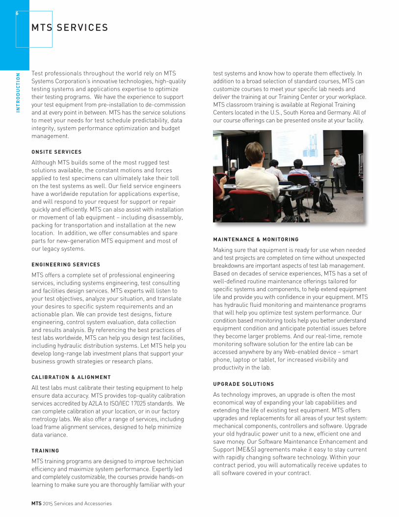
TRAINING
MTS training programs are designed to improve technician efficiency and maximize system performance. Expertly led and completely customizable, the courses provide hands-on learning to make sure you are thoroughly familiar with your
MTS SERVICES
test systems and know how to operate them effectively. In addition to a broad selection of standard courses, MTS can customize courses to meet your specific lab needs and deliver the training at our Training Center or your workplace. MTS classroom training is available at Regional Training Centers located in the U.S., South Korea and Germany. All of our course offerings can be presented onsite at your facility.
MAINTENANCE & MONITORING
Making sure that equipment is ready for use when needed and test projects are completed on time without unexpected breakdowns are important aspects of test lab management. Based on decades of service experiences, MTS has a set of well-defined routine maintenance offerings tailored for specific systems and components, to help extend equipment life and provide you with confidence in your equipment. MTS has hydraulic fluid monitoring and maintenance programs that will help you optimize test system performance. Our condition based monitoring tools help you better understand equipment condition and anticipate potential issues before they become larger problems. And our real-time, remote monitoring software solution for the entire lab can be accessed anywhere by any Web-enabled device – smart phone, laptop or tablet, for increased visibility and productivity in the lab. UPGRADE SOLUTIONS
As technology improves, an upgrade is often the most economical way of expanding your lab capabilities and extending the life of existing test equipment. MTS offers upgrades and replacements for all areas of your test system: mechanical components, controllers and software. Upgrade your old hydraulic power unit to a new, efficient one and save money. Our Software Maintenance Enhancement and Support (ME&S) agreements make it easy to stay current with rapidly changing software technology. Within your contract period, you will automatically receive updates to all software covered in your contract.

SE
RV
ICE
S
7
MTS 2015 Services and Accessories
TRAININGCourse Selection
Factory Training Courses Test System Operation & Application Theory Courses DIEN CODE
MTS Hardware & Analog Controllers √ √ TRMHAC
Damper Test System Operation √ TRDTSODurability Testing Technology √ √ TRDTTElastomer Testing on Controllers with MTS Series 793 Software √ √ TRETC793Measurement Uncertainty √ TROTMUTest Rig Design √ TRTRDMaterials Test Lab Management √ TRMTL
Software Operation Courses DIEN CODE
MTS Hardware Concepts & MTS Series 793 Software √ √ TRCAHOMTW MTS Series 793 Advanced Software Operation √ TR793ASOMTS Series 793 Software with MultiPurpose TestWare® (MPT) Test Design √ √ √ TRCAMTSMTS MultiPurpose TestWare (MPT) Software √ √ √ TRMMTSMTS Series 793 Software with MTS TestSuite (mpe) Test Design √ √ √ TRCAMTSMSMTS TestSuite Multipurpose Elite (mpe) Software √ √ √ TRMTSMSMTS TestSuite TW Elite (TWE) Software √ √ √ TRTSTWEMTS TestWorks® 4 Software √ √ TRCATSAeroPro Operator √ TRAPOAeroPro Administrator √ TRAPAFatigue & Fracture with MTS TestSuite (mpe) Software √ TRFFScRPC Pro Software Operation √ √ √ TRCFPSO
RPC® Pro Software Operation √ √ √ TRRPSORPC Pro Advanced Software Operation √ √ √ TRRPASOCombined RPC Pro Operator & Basic RPC Pro Fatigue √ √ TRCRPOBRPF
Training Alternatives*MTS can provide onsite presentations of all course offerings. MTS also has the expert capability to develop custom courses on a broad range of test-related subjects not covered in the course schedule. (Please allow three months for onsite course scheduling.)
ONSITE COURSE DIEN CODE
Per day onsite training - 1 to 8 students with 1 instructor TROD
Add per second instructor for class size above 8 - check availability for second instructor TROAI
Add per student above 8 (Class size limit of 15) TROAS
REMOTE ONLINE COURSE
Per hour online training - 1 to 8 students with 1 instructor TRRPH
Add per student above 8 (Class size limit of 15) TRRAS
Training/Consulting PackageDESCRIPTION DIEN CODE
MTS TestSuite TWE Training/Consulting Package (2 days software training plus 2 days consulting, on custom test methods) TRTSTWETCP
Cancellation FeeDESCRIPTION DIEN CODE
If cancelled less than one week prior to course start TRCANFEE
Price for a course held at MTS includes tuition, class material and lunchMTS training center classroom size is limited,, check for availability*Price plus airfare and zone charges for instructor(s)*For onsite courses with more than 8 students, contact MTS for second instructor availability*Please allow 3 months for onsite course schedulingWe welcome your requests for custom classes or your language needs
AM
ERIC
AS
TRA
ININ
G C
ENTE
R
ASI
A T
RA
ININ
G C
ENTE
R
EUR
OP
E TR
AIN
ING
CEN
TER
SE
RV
ICE
S8
MTS 2015 Services and Accessories
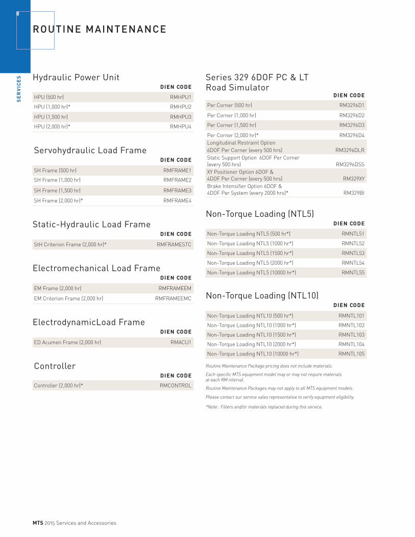
ROUTINE MAINTENANCE
Hydraulic Power Unit DIEN CODE
HPU (500 hr) RMHPU1
HPU (1,000 hr)* RMHPU2
HPU (1,500 hr) RMHPU3
HPU (2,000 hr)* RMHPU4
Servohydraulic Load Frame DIEN CODE
SH Frame (500 hr) RMFRAME1
SH Frame (1,000 hr) RMFRAME2
SH Frame (1,500 hr) RMFRAME3
SH Frame (2,000 hr)* RMFRAME4
Static-Hydraulic Load Frame DIEN CODE
StH Criterion Frame (2,000 hr)* RMFRAMESTC
Electromechanical Load Frame DIEN CODE
EM Frame (2,000 hr) RMFRAMEEM
EM Criterion Frame (2,000 hr) RMFRAMEEMC
ElectrodynamicLoad Frame DIEN CODE
ED Acumen Frame (2,000 hr) RMACU1
Controller DIEN CODE
Controller (2,000 hr)* RMCONTROL
Series 329 6DOF PC & LTRoad Simulator DIEN CODE
Per Corner (500 hr) RM3296D1
Per Corner (1,000 hr) RM3296D2
Per Corner (1,500 hr) RM3296D3
Per Corner (2,000 hr)* RM3296D4Longitudinal Restraint Option 6DOF Per Corner (every 500 hrs) RM3296DLRStatic Support Option 6DOF Per Corner (every 500 hrs) RM3296DSSXY Positioner Option 6DOF & 4DOF Per Corner (every 500 hrs) RM329XYBrake Intensifier Option 6DOF & 4DOF Per System (every 2000 hrs)* RM329BI
Non-Torque Loading (NTL5) DIEN CODE
Non-Torque Loading NTL5 (500 hr*) RMNTL51
Non-Torque Loading NTL5 (1000 hr*) RMNTL52
Non-Torque Loading NTL5 (1500 hr*) RMNTL53
Non-Torque Loading NTL5 (2000 hr*) RMNTL54
Non-Torque Loading NTL5 (10000 hr*) RMNTL55
Non-Torque Loading (NTL10) DIEN CODE
Non-Torque Loading NTL10 (500 hr*) RMNTL101
Non-Torque Loading NTL10 (1000 hr*) RMNTL102
Non-Torque Loading NTL10 (1500 hr*) RMNTL103
Non-Torque Loading NTL10 (2000 hr*) RMNTL104
Non-Torque Loading NTL10 (10000 hr*) RMNTL105
Routine Maintenance Package pricing does not include materials.
Each specific MTS equipment model may or may not require materials at each RM interval.
Routine Maintenance Packages may not apply to all MTS equipment models.
Please contact our service sales representative to verify equipment eligibility.
*Note: Filters and/or materials replaced during this service.

SE
RV
ICE
S
9
MTS 2015 Services and Accessories
Tire Rolling Resistance - Hydraulic DIEN CODE
Tire Rolling Resistance - Hydraulic (500 hr)* RMRRH1
Tire Rolling Resistance - Hydraulic (1000 hr)* RMRRH2
Tire Rolling Resistance - Hydraulic (1500 hr)* RMRRH3
Tire Rolling Resistance - Hydraulic (2000 hr)* RMRRH4
Tire Rolling Resistance - Hydraulic CarriageOption (500 & 1500 hr) RMRRHO1
Tire Rolling Resistance - Hydraulic CarriageOption (1000 & 2000 hr)* RMRRHO2
Tire Rolling Resistance - Electric DIEN CODE
Tire Rolling Resistance - Electric (500 hr)* RMRRE1
Tire Rolling Resistance - Electric (1000 hr)* RMRRE2
Tire Rolling Resistance - Electric (1500 hr)* RMRRE3
Tire Rolling Resistance - Electric (2000 hr)* RMRRE4
Tire Rolling Resistance - Electric CarriageOption (500 & 1500 hr) RMRREO1
Tire Rolling Resistance - Electric CarriageOption (1000 & 2000 hr)* RMRREO2
Tire Tread Wear Simulation DIEN CODE
Tire Tread Wear - Hydraulic (500 hr)* RMTWH1
Tire Tread Wear - Hydraulic (1000 hr)* RMTWH2
Tire Tread Wear - Hydraulic (1500 hr)* RMTWH3
Tire Tread Wear - Hydraulic (2000 hr)* RMTWH4
Tire Tread Wear - Hydraulic Carriage Option (500 & 1500 hr) RMTWHO1
Tire Tread Wear - Hydraulic Carriage Option (1000 & 2000 hr)* RMTWHO2
Routine Maintenance Package pricing does not include materials.
Each specific MTS equipment model may or may not require materials at each RM interval.
Routine Maintenance Packages may not apply to all MTS equipment models.
Please contact our service sales representative to verify equipment eligibility.
*Note: Filters and/or materials replaced during this service.
MTS Fluid Care Program DIEN CODE
Program Management Per Sample Point FCPCONSULT
FSE Sampling Per Bottle (see hydraulic tools for bottle P/N)
MTS Fluid Analysis
D.I.Y. Sampling Per Bottle (see hydraulic tools for bottle P/N)
FSE Sampling Per Bottle (see hydraulic tools for bottle P/N)
MTS Sample Tool for D.I.Y. Sampling (see hydraulic tools for bottle P/N)
Fluid Replacement Service* DIEN CODE
Replace hydraulic fluid (systems <30 gpm) RMFLUIDCHG1
Replace hydraulic fluid (systems 30 to 100 gpm) RMFLUIDCHG2
*Fluid is not included and customer is responsible for disposal
ROUTINE MAINTENANCE & FLUID ASSESSMENT SERVICES

SE
RV
ICE
S10
MTS 2015 Services and Accessories
ONSITE CALIBRATION SERVICES
Calibration Standards Fee DIEN CODE
One charge per calibration incident CALSTDLoad Cells 0-300 kN, LVDT, etc.Load Cells 500-5000 kN and Torque*
» Pricing is based on specimen and fixturing removed, leaving the system ready to be calibrated. Additional time required to prepare the system for calibration will be charged at current Field Service Engineer rates.
» Consult factory for models not listed.
» Calibrations are to current revision of applicable standard unless otherwise noted.
» ASTM E4 certification may not apply to electromechanical calibrations.
* This standards fee can vary by country. Please contact your local MTS representative.
Load Cell to Relevant ASTM E4 or ISO 7500 Standards***FIRST READOUT DEVICE DIEN CODE
Deadweight up to 100 lbs DWTO100
Axial 0 to 1 KIP Metric Equivalent 0 to 5 kN** (Single range Acumen only / 2 to 100% full-scale) 0T1KA
Axial 0 to 5 KIP Metric Equivalent 0 to 25 kN (Single range EM &Criterion/10 to 100% full-scale) 0T5KA
Axial 0 to 20 kip Metric Equivalent–0 to 100 kN[up to 2 ranges (tension/compression)] 0T20KA
Axial 0 to 100 kip Metric Equivalent–0 to 250 kN [up to 2 ranges (tension/compression) 0T100KA
Axial 0 to 240 kip Metric Equivalent–0 to 500 kN [up to 2 ranges (tension/compression)] 0T240KA
Axial 0 to 500 kip Metric Equivalent–0 to 2000 kN [up to 2 ranges (tension/compression) 0T500KA
Axial 0 to 1000 kip Metric Equivalent–0 to 5000 kN [up to 2 ranges (tension/compression)] 0T1000KA
Torque 0 to 60K inch-pound Metric Equivalent
(0 to 6800 Nm) 1 range 0T60KT
Torque 0 to 200K inch-pound Metric Equivalent
(0 to 22000 Nm) 1 range 0T200KT
Torque 0 to 750K inch-pound Metric Equivalent
(0 to 85000 Nm) 1 range 0T750KT
ASTM E4 or ISO 7500*** readout verification, each additional readout device/additional bridges ASTME4
** For multiple ranges, use the Axial 0 to 20 kip.
CRITERION SYSTEMS (EM ONLY) - SINGLE RANGE DIEN CODE
Force Calibration, Deadweight up to 500 N Criterion EM only(Single range 0.5% / 10 to 100% full-scale) ODW500NCEM
Axial Force Calibration 0 to 30 kN Criterion EM only (Single range 0.5% / 10 to 100% full-scale) OA30KNCEM
Axial Force Calibration 0 to 100 kN Criterion EM only(Single range 0.5% / 10 to 100% full-scale) OA100KNCEM
Axial Force Calibration 0 to 300 kN Criterion EM only (Single range 0.5% / 10 to 100% full-scale) OA300KNCEM
Axial Force Calibration 0 to 600 kN Criterion EM only (Single range 0.5% / 10 to 100% full-scale) OA600KNCEM
CRITERION SYSTEMS (EM ONLY) - EXTENDED RANGE DIEN CODE
Axial Force Calibration - Extended Range, 0 to 30 kN Criterion EM Only (Extended range 0.5% / at points below 10% full-scale) OA30KNCEMER
Axial Force Calibration - Extended Range, 0 to 100 kN Criterion EM Only (Extended range 0.5% / at points below 10% full-scale) OA100KNCEMER
*** Accreditation can vary by country. Please contact your local MTS representative to confirm
MULTI-AXIS FORCE TRANSDCUCER (LOAD CELL) DIEN CODE
Bi-axial (restraint) load cellModel 670.67B-03/04 BIAXCAL1Model 670.67B-10/11 BIAXCAL2Tri-axial 833 Elastomer load cellUtilizing hardware Matrix box(Matrix module and system controller required) TRIAXCAL1
Tri-axial 833 Elastomer load cellUtilizing SW and calculated channels(System controller with conditioners required) TRIAXCAL2
Displacement transducersTYPE DIEN CODE
Acumen Displacement Calibration DTACU
Servo-hydraulic displacement (LVDT) LVDT
Rotary position transducer RVDT
Delta P transducer DELTAPCAL
Electromechanical test system verification (includes both Speed and Displacement) SPDT
Speed and Displacement Criterion EM only (Single Range 0.5% / Displacement to ASTM E2309) OSPDTCEM

SE
RV
ICE
S
11
MTS 2015 Services and Accessories
Crack-Opening Displacement Gages (COD)
Calibration of COD gages for use in compliance with ASTM** E399, E561, E1290, and E1820.
ASTM CRACK OPENING DISPLACEMENT GAGE/DEFLECT METER DIEN CODE
Calibration CODCAL(Models covered: 632.02, 632.03, 632.05, 632.06, and equivalents)
** ASTM E399 standard test method for plane-strain fracture toughness of metallic materials.
ASTM E561 standard practice for R-curve determination.
ASTM E1290 standard test method for crack-tip opening displacement (CTOD) fracture toughness measurement.
ASTM E1820 standard test method for measurement of fracture toughness.
Extensometer Calibration to Relevant ASTM E83/ISO 9513 Standards DIEN CODE
Axial Extensometers (per extensometer) AXIALEXTCAL
(Models Covered: 632.11, 632.12, 632.24, 632.25, 632.27, 632.29,
632.31, 632.90, 632.94, 634.12, 634.25, 634.28 & Equivalents)
Bi-Axial Extensometers BIAXIALEXTCAL
(Models Covered: 632.8X & Equivalents)
Diametral Extensometers DIAEXTCAL
(Models Covered: 632.18, 632.19, 632.20 & Equivalents)
Averaging Axial Extensometers AVGEXTCAL
(Models Covered: 632.17 & Equivalents)
Cross Sectional Strain Extensometers CSSTREXTCAL
(Models Covered: 632.23 & Equivalents)
High Temperature Axial Extensometers HITEMPEXTCAL
(Models Covered: 632.4X, 632.5X, 632.6X & Equivalents)
Immersible Extensometers IMMEXTCAL
(Models Covered: 632.70 & Equivalents)
Small Gage Length Extensometers SGLEXTCAL
(Models Covered: 632.13, 632.26 & Equivalents)
Circumferential Extensometers CIREXTCAL
(Models Covered: 632.92 & Equivalents)
High Elongation Extensometers HIELEXTCAL
(Models Covered: DXL-Ext & Equivalents)
Biomedical Extensometers BIOEXTCAL
(Models Covered: 632.32 & Equivalents)
Other Calibration Items DIEN CODE
LDH machine calibrations 866.5X LDH866.5X
ONSITE CALIBRATION SERVICES
Time and Material CalibrationsSome systems must be calibrated under a time and material method. An example would be a system without a load unit that requires the use of a fabricated reaction base. Standard load unit systems will always be calibrated under the fixed fee method. When a system is calibrated using the time and material method, these charges apply:
» Time-and-material Standards fee for each standard used.
» Each additional load cell using the same load cell standard.
» Zone charges (based on applicable zone charge).
» Labor (based on applicable labor rate).
Flat-Trac CalibrationsFlat-Trac calibrations should be performed at least annually, or when any component in the chain of mechanical or electrical components comprising a selected software channel is replaced or repaired.
New Matrix Current Matrix Generation Calibration Calibration Only
DIEN CODE DIEN CODE
Free rolling calibration NMFTCFR CMFTCFREach additional free rolling matrix NMFTCFRA CMFTCFRA
Adder for spindle drive calibration NMFTCSD CMFTCSDEach additional spindle drive matrix NMFTCSDA CMFTCSDA
Slip angle calibration (stand-alone) CMFTCSA
Camber angle calibration (stand-alone) CMFTCCA New Matrix Generation pricing includes the following activities when applicable:
» A/D and D/A calibrations
» Camber angle calibration
» Slip angle calibration
» Calibrating the calibration standard (Flat-Trac II)
» Force and moment calibration
» Belt speed calibration
» Generation of calibration matrix
» Pre- and post-calibration data
» Verify inertial compensation (Flat-Trac III)
» Calibrate inflation pressure
» Calibrate ambient and tire temperatures
» Spindle speed calibration
» Shunt calibration
» Loaded radius calibration
» Verification of matrix through calibration check.

SE
RV
ICE
S12
MTS 2015 Services and Accessories
ONSITE CALIBRATION SERVICES
Calibration for 329 Passenger Road SimulatorsLOAD CELLS AND DISPLACEMENT TRANSDUCER CALIBRATION
Without brake With brake DIEN CODE DIEN CODE
Corner CORNERA CORNERAB
1/2 Car HALFCARA HALFCARAB
Full Car FULLCARA FULLCARAB
LOAD CELL CALIBRATION (ONLY)
Corner CORNERL CORNERLB
1/2 Car HALFCARL HALFCARLB
Full Car FULLCARL FULLCARLB
DISPLACEMENT TRANSDUCER CALIBRATION (ONLY)
Corner CORNERD CORNERDB
1/2 Car HALFCARD HALFCARDB
Full Car FULLCARD FULLCARDB
Calibration for 329 LT Road SimulatorsLOAD CELLS AND DISPLACEMENT TRANSDUCER CALIBRATION
Without brake With brake DIEN CODE DIEN CODE
Corner LTCORNERA LTCORNERAB
1/2 Truck LTHALFCARA LTHALFCARAB
Full Truck LTFULLCARA LTFULLCARAB
LOAD CELL CALIBRATION (ONLY)
Corner LTCORNERL LTCORNERLB
1/2 Truck LTHALFCARL LTHALFCARLB
Full Truck LTFULLCARL LTFULLCARLB
DISPLACEMENT TRANSDUCER CALIBRATION (ONLY)
Corner LTCORNERD LTCORNERDB
1/2 Truck LTHALFCARD LTHALFCARDB
Full Truck LTFULLCARD LTFULLCARDB
Note: zone charges are not included in pricing.
Calibration of Multi-Axial Simulation Table (MASTTM) Systems6 CHANNELMAST END-TO-END-CALIBRATION DIEN CODE
Package 1 6 accelerometers 6MASTACC
Package 2 6 accelerometers and 6 LVDT 6MASTACCL
Package 3 6 accelerometers, 6 LVDT, and ASC D/A-A/D 6MASTACCLAD
Notes:- Prices include calibration standard fee but travel expenses (zone, airfare, etc.) are not included.
- These packages are not eligible for volume discounts offered on other calibrations.
- AMP and VPP discounts will apply.
Onsite Accelerometer Calibration
ACCELEROMETERS CALIBRATION PRICES
Type DIEN CODE
Single Axis- Transducer only ACC
Tri-Axis - Transducer only TRIAC
Single Axis - Transducer with conditioner ACCCOND
Tri-Axis - Transducer with conditioner TRIACC
Static Alignment Verification
STATIC ALIGNMENT VERIFICATION PRICES
Type DIEN CODE
Static twelve gage alignment STATIC12
(For more on alignment see Service Notes section).
Dynamic Force Verification
DYNAMIC FORCE VERIFICATION PRICES
Type DIEN CODE
Dynamic Force Verification DYNAMICCAL
Additional frequency/range combinations ADDFR

SE
RV
ICE
S
13
MTS 2015 Services and Accessories
FACTORY CALIBRATION SERVICES
Factory Calibration Prices
LOAD CELL
Calibration up to 220,000 lbf (As Found / As Left Data Provided) Single Range / Single Readout Device* DIEN CODE
Axial up to 22 kip (Metric Equivalent–up to 100 kN ) FCFTA1
Additional Range / Readout Device FCADDR
Axial >22 kip to 240 kip (Metric Equivalent- >100 kN to 1000 kN) FCFTA2
Additional Range / Readout Device FCADDR
MULTI-AXIS LOAD CELL
Bi-axial (restraint) load cellModel 670.67B-03/04 FCBARFT1Model 670.67B-10/11 FCBARFT2
Tri-axial 833 Elastomer load cellUtilizing hardware Matrix box(Matrix module and system controller required) FCTAEFT1
Tri-axial 833 Elastomer load cellUtilizing SW and calculated channels(System controller with conditioners required) FCTAEFT2
TORQUE TRANSDUCER
Calibration up to 12,000 lbf-in (As Found / As Left Data Provided)
Torque up to 12,000 lbf-in Metric Equivalent- up to 1300 N•m Single Range / Single Readout Device FCTCT1
Additional Range / Readout Device FCADDR
COD GAUGES
Model 632.02 & 632.03 Clip-on displacement gage FCCOD1
Model 632.06 1 Arm Bandit displacement gage FCCOD2
EXTENSOMETER**
Single Range / Single Readout Device*(As Found / As Left Data Provided)
Axial Extensometers (per extensometer) (Models Covered: 632.11, 632.12, 632.24, 632.25, 632.27, 632.29, 632.90, 632.94, 634.12, 634.25, 634.28, 634.31 & Equivalents) FCEA
Bi-Axial Extensometers (Models Covered: 632.8X & Equivalents) FCEBA
Diametral Extensometers (Models Covered: 632.18, 632.19, 632.20 & Equivalents) FCEDE
Averaging Axial Extensometers (Models Covered: 632.17 & Equivalents) FCEAA
DIEN CODE
Cross Sectional Strain Extensometers (Models Covered: 632.23 & Equivalents) FCECSS
High Temperature Axial Extensometers (Models Covered: 632.4X, 632.5X, 632.6X & Equivalents) FCEHTA
Immersible Extensometers (Models Covered: 632.70 & Equivalents) FCEI
Small Gage Length Extensometers (Models Covered: 632.13, 632.26 & Equivalents) FCESGL
Circumferential Extensometers (Models Covered: 632.92 & Equivalents) FCEC
High Elongation Extensometers (Models Cov : DXL-Ext & Equivalents) FCEHE
Biomedical Extensometers (Models Covered: 632.32 & Equivalents) FCEB
Additional Range/Readout Device FCADDR
* Single Range (Minimum of 9 data points from 2% to 100%. Applies to 493 and 494 product lines except 493.21 and 494.21) ** Not relevant to ASTM E83 or ISO9513 Standards
SWIFT System Calibrations .
SWIFT CALIBRATION PRICES ARE PER CALIBRATION* Model DIEN CODE
SWIFT 10, 20, 30, & 40 transducer* FCSW1
SWIFT 45 & 50* FCSW2 SWIFT LOANERS AVAILABLE WITH CALIBRATION*Model DIEN CODE
SWIFT 20, 30, & 40 units FCSWL1
SWIFT 45 & 50 units FCSWL2
* SWIFT Loaners only available for use During Customer Transducer Calibrations at MTS factory* Loaners are available on first come, first served basis only* Price is for Aluminum, Titanium or Stainless Steel units* Price includes Spinning and Non-spinning accessories* Loaner prices are based on 1 loaner unit of the duration of 1 SWIFT multi-axial transducer calibration* Prices do not include rims and /or hub adapters* Loaner and Calibration prices are fixed regardless of how long the calibration takes* Customer needs to return loaner within 72 hours after receiving calibrated SWIFT, otherwise additional loaner fee’s will apply* Prices are subject to change without notice
*Rental of SWIFT transducer is no longer available
SE
RV
ICE
S14
MTS 2015 Services and Accessories
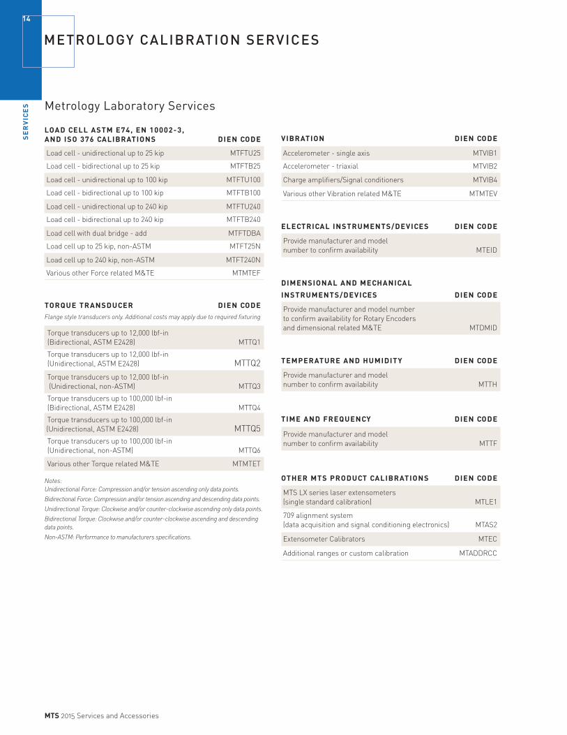
METROLOGY CALIBRATION SERVICES
Metrology Laboratory Services
LOAD CELL ASTM E74, EN 10002-3, AND ISO 376 CALIBRATIONS DIEN CODE
Load cell - unidirectional up to 25 kip MTFTU25
Load cell - bidirectional up to 25 kip MTFTB25
Load cell - unidirectional up to 100 kip MTFTU100
Load cell - bidirectional up to 100 kip MTFTB100
Load cell - unidirectional up to 240 kip MTFTU240
Load cell - bidirectional up to 240 kip MTFTB240
Load cell with dual bridge - add MTFTDBA
Load cell up to 25 kip, non-ASTM MTFT25N
Load cell up to 240 kip, non-ASTM MTFT240N
Various other Force related M&TE MTMTEF
TORQUE TRANSDUCER DIEN CODEFlange style transducers only. Additional costs may apply due to required fixturing
Torque transducers up to 12,000 lbf-in (Bidirectional, ASTM E2428) MTTQ1
Torque transducers up to 12,000 lbf-in (Unidirectional, ASTM E2428) MTTQ2
Torque transducers up to 12,000 lbf-in (Unidirectional, non-ASTM) MTTQ3
Torque transducers up to 100,000 lbf-in (Bidirectional, ASTM E2428) MTTQ4
Torque transducers up to 100,000 lbf-in (Unidirectional, ASTM E2428) MTTQ5Torque transducers up to 100,000 lbf-in (Unidirectional, non-ASTM) MTTQ6
Various other Torque related M&TE MTMTET
Notes: Unidirectional Force: Compression and/or tension ascending only data points.
Bidirectional Force: Compression and/or tension ascending and descending data points.
Unidirectional Torque: Clockwise and/or counter-clockwise ascending only data points.
Bidirectional Torque: Clockwise and/or counter-clockwise ascending and descending data points.
Non-ASTM: Performance to manufacturers specifications.
VIBRATION DIEN CODE
Accelerometer - single axis MTVIB1
Accelerometer - triaxial MTVIB2
Charge amplifiers/Signal conditioners MTVIB4
Various other Vibration related M&TE MTMTEV
ELECTRICAL INSTRUMENTS/DEVICES DIEN CODE
Provide manufacturer and model number to confirm availability MTEID
DIMENSIONAL AND MECHANICAL
INSTRUMENTS/DEVICES DIEN CODE
Provide manufacturer and model number to confirm availability for Rotary Encoders and dimensional related M&TE MTDMID
TEMPERATURE AND HUMIDITY DIEN CODE
Provide manufacturer and model number to confirm availability MTTH
TIME AND FREQUENCY DIEN CODE
Provide manufacturer and model number to confirm availability MTTF
OTHER MTS PRODUCT CALIBRATIONS DIEN CODE
MTS LX series laser extensometers (single standard calibration) MTLE1
709 alignment system (data acquisition and signal conditioning electronics) MTAS2
Extensometer Calibrators MTEC
Additional ranges or custom calibration MTADDRCC

SE
RV
ICE
S
15
MTS 2015 Services and Accessories
ACTUATOR REMANUFACTURE PROGRAM
Model 204.xxMODEL NUMBER RATING DIEN CODE
204.08 1.1 kip RA20408
204.09 2.2 kip RA20409
204.11 2.5 kip RA20411
204.12 4.0 kip RA20412
204.13 6.0 kip RA20413
204.21 6.0 kip RA20421
204.22 9.0 kip RA20422
204.23 12 kip RA20423
204.24 20 kip RA20424
204.25 24 kip RA20425
204.26 35 kip RA20426
204.31 50 kip RA20431
204.32 70 kip RA20432
204.41 100 kip RA20441
204.42 150 kip RA20442
204.51 3.3 kip RA20451
204.52 5.5 kip RA20452
204.61 11 kip RA20461
204.62 15 kip RA20462
204.63 22 kip RA20463
204.64 35 kip RA20464
204.71 55 kip RA20471
204.72 77 kip RA20472
204.81 110 kip RA20481
204.82 165 kip RA20482
204.91 220 kip RA20491
Note: These units are no longer in new production, replacement of these units is not possible.
Model 231.xx to 248.xxMODEL NUMBER RATING DIEN CODE
231.xx RA231xx
242.xx RA242xx
244.11 3.3 kip RA24411
244.12 5.5 kip RA24412
244.20 15 kip RA24420
244.21 11 kip RA24421
244.22 22 kip RA24422
244.23 35 kip RA24423
244.31 55 kip RA24431
244.41 110 kip RA24441
244.51 220 kip RA24451
248.xx RA248xx
The replacement prices listed are for standard 6” & 10” stroke actuators. Consult MTS for replacement pricing of non-typical actuators.
Load Units with Integral ActuatorsMODEL NUMBER RATING DIEN CODE
318.10 3.3 kip RA31810K33
318.10 5.5 kip RA31810K55
318.10 11 kip RA31810K11
318.10/25 22 kip RA3181025K22
318.25/50 55 kip RA3182550K55
318.50 110 kip RA31850K110
The replacement prices listed are for standard 6” & 10” stroke actuators. Consult MTS for replacement pricing of non-typical actuators.Installation is not included in the remanufacture price.
Model 242.xx to 244.51 End Cap RemanufacturingMODEL NUMBER RATING DIEN CODE
242.xx
244.11 3.3 kip
244.12 5.5 kip
244.20* 15 kip RACAP24420
244.21* 11 kip RACAP24421
244.22 22 kip RACAP24422
244.23 35 kip RACAP24423
244.31 55 kip RACAP24431
244.41 110 kip RACAP24441
244.51 220 kip RACAP24451
*Steel version onlyPrices are for each end cap.

SE
RV
ICE
S16
MTS 2015 Services and Accessories
Note: 793 controller system software ME&S AND ALL 793 application software ME&S must be purchased together for the AMP ME&S to be valid. Customer must have purchase the latest version of software in order to purchase ME&S. An upgrade in software may require a FlexTest controller upgrade.**
**Note that the Power PC processors used in some FTIIm controllers need to be replaced with new versions in order to support upgrade to current software.
The following processors need to be replaced: -Model 498.93, 160X-series-Model 498.95-1, 2700 series
The following processors might not deliver satisfactory performance depending on configuration and application:-Model 498.96-2, 2431-series-Model 498.96-3, 5101-series
***Available only for customers with PC automation.
The ME&S software is currently under your system warranty or under an existing ME&S contract. If this is not the case, additional fees will apply.
For RPC and TestSuite software, a catch-up fee equal to 50% of the back ME&S on your software will be applied.
For Series 793 software, please contact your service sales engineer for quote.
When ME&S is purchased, it must be purchased for all licenses and options purchased. Partial coverage is not permitted.
Application Software
SOFTWARE MODULE DIEN CODE
MTS TestSuite Multipurpose Elite SMTSME Multipurpose Express SMTSMX Fatigue Analyzer SMTSFA1 Reporter Add-In SMTSR Low Cycle Fatigue Module (LCF) SMTSLCF High Cycle Fatigue Module (HCF) SMTSHCF Advanced Low Cycle Fatigue Module (ADVLCF) SMTSALCF FCG Crack Gage SMTSCG1 FCG Clip Gage SMTSCG2 FCG DCPD SMTSDCPD Fracture Toughness KIC SMTSKIC Fracture Toughness JIC SMTSJIC Fracture Toughness CTOD SMTSCTOD Fracture Analyzer SMTSFA2 K-R Curve Determination SMTSKRCD Thermomechanical Fatigue Module SMTSTMF Tensile Module SMTSTM Bi-Directional Database Interface SMTSDBI TW Elite Servohydraulic SMTSTWESH TW Express Servohydraulic SMTSTWXSH TW Elite Criterion/Insight® SMTSTWECI TW Essential Criterion/Insight SMTSTWSCI TW Express Criterion/Insight SMTSTWXCI TW Plastics Bundle EM SMTSTWPEM TW Metals Bundle EM SMTSTWMEM TW Metals Bundle STH SMTSTWMSTH TW Construction Bundle EM SMTSTWCEM TW Construction Bundle STH SMTSTWCSTH TW EM/STH Individual Template from Plastics/Metal/Construction Bundle SMTSTWT TW Multi-Cycle Bundle EM SMTSTWMCEM TW Multi-Cycle Bundle STH SMTSTWMCSTH TW Adv Rate Control for EM/SH SMTSTWARC TW MULTICHANNEL SMTSTWMCH TW Strain 1 SMTSTWS1 TW Strain 1&2 SMTSTWS12 Advanced HCF Module SMTSAHCF
SOFTWARE MAINTENANCE Software Maintenance, Enhancement, and Support (ME&S)
MTS Software Maintenance, Enhancement, and Support (ME&S) agreements are an easy and cost-effective way to keep pace with rapidly changing technologies. Receive all software updates (maintenance) and software upgrades (enhancement) that become available during the contract period for the initially purchased product. New features that are sold as options or separate product are not included, but are available for an additional charge.
» Twelve consecutive months of coverage
» Access to technical support by phone during the contract period

SE
RV
ICE
S
17
MTS 2015 Services and Accessories
793 Controller System Software SOFTWARE MODULE DIEN CODE
793 System Software Supports FlexTest 40 and FlexTest SE Controllers without MPT SMLSAFTSENMPT
793 System Software Supports FlexTest 60/100/200 and FlexTest GT Controllers without MPT SMLSAFTGTNMPT
793 System Software & Supports FlexTest 40 and FlexTest SE Controllers SMLSAFTSE
Multipurpose TestWare***
793 System Software & Supports FlexTest 60/100/200 and FlexTest GT Controllers SMLSAFTGT Multipurpose TestWare***
Note: Japanese language support all controllers listed above
793 Application Software SOFTWARE MODULE DIEN CODE
Elastomer Applications 793.30 Elastomer ExpressTM SM793EEX
(for 793.XX applications only) 793.31 Dynamic Characterization SM793EDC
793.32 Advanced Dynamic Characterization SM793EAD
793.33 Static Deflection SM793ESD
793.35 Elastomer QC SM793EEQ
793.17 Dynamic Property Monitor SM793EDP
793.37 Resonance Search SM793ERS
793.39 Elastomer Command Process SM793EEC
Basic Elastomer Application Bundle Includes 793.31, 793.32, 793.33 SM793EBE
QC Elastomer Application Bundle Includes 793.31, 793.32, 793.33 and 793.35 SM793EEA
Durability Elastomer Application Bundle Includes 793.31, 793.32, 793.33 plus 793.17. SM793EDE
Full Elastomer Application Bundle Includes 793.31, 793.32, 793.33, 793.17, 793.35, 793.37 and 793.39. SM793EFE
Damper Test MTS Damper Software Includes all customer purchased options SMLSADT
Wind/Civil Engineering Materials 793.38 Blade Resonance SM793WCBR
Test Application Software 793.61 Uniaxial Rock Mechanics SM793GCEURM
793.62 Triaxial Rock Mechanics SM793GCETRM
793.63 Rock Fracture Mechanics SM793GCERFM
793.66 Construction Materials SM793GCECM
793.67 Pavement Materials SM793GCEPM
Civil Structures Pseudodynamic Testing Software SM793GCEPT
Bi-Axial Pseudodynamic Testing Software SM793GCEBPT
793.18 Run-time Ramp Command SM793GCERRC
MTS Computer Simulation Interface & Configurator SM793GCESIC
Note: 793 controller system software ME&S AND ALL 793 application software ME&S must be purchased together for the AMP ME&S to be valid. Customer must have/purchase the latest version of software in order to purchase ME&S. An upgrade in software may require a FlexTest controller upgrade.
SOFTWARE MAINTENANCE Software Maintenance, Enhancement, and Support (ME&S)

SE
RV
ICE
S18
MTS 2015 Services and Accessories
Standalone Software SOFTWARE MODULE DIEN CODE
TestWorks V4.0 S/H Systems Application software & all options SMLSATW
TestWorks V4.0 E/M Systems Operating system software & all application software packages SMLSATW4
709 Alignment 709 Alignment System (PC) Software Includes Alignment Wizard and content sensitive help SMLSA709
AeroPro Software for AeroST or AeroPro Control & SDAC License (small & large) SMSAFTAPS
FlexTest hardware (793 controller AeroPro Control SMSAFTPC
system software ME&S included) AeroPro SDAC, Small System (1200 Channels or less) SMSAFTAPSS
AeroPro SDAC, Large System (1201 Channels or more) SMSAFTAPSL
AeroPro Calculations in the Loop SMSAFTAPCL
Digital Data Interface (DDI) SMSAFTDDI
AeroPro API (SDK) SMSAFTAPAPI
Data Reprocessor SMSAFTDR
C3 (Cross Coupling Compensation) SMSAFTC3
AeroPro Signal Based Command SMSAFSBC
AeroPro Mode Switching SMSAFMS
AeroPro Phase Control SMSAFPC
AeroPro Redundant Load Checker SMSAFRLC
793 DDI Access SMSAF793DDI
Position Display SMSAFPD
Trend Monitoring SMSAFTTM
Data Display SMSAFDD
Peak Valley Recorder SMSAFPVR
Note: Customer must have/purchase the latest version of software in order to purchase ME&S.
SOFTWARE MAINTENANCE Software Maintenance, Enhancement, and Support (ME&S)

SE
RV
ICE
S
19
MTS 2015 Services and Accessories
RPC Software Products
SOFTWARE MODULE DIEN CODE
GROUND VEHICLE DURABILITY TESTING & ROAD SIMULATION SOFTWARE
cRPC Pro Pro Drive File Development and Test Package SMCRPCPDFDTP
Drive File Development Package SMCRPCDFDP
Simulation Package SMCRPCSP
Durability Test Package (including one monitoring option) SMCRPCDTP
Data Validation Package SMCRPCDVP
Edit and Analysis Package SMCRPCEAP
Options
Time History Fatigue SMCRPCTHF
Fatigue Sensitive Editing SMCRPCFSE
Histogram Analysis SMCRPCHA
Component Test Generation SMCRPCCTG
Simultaneous Excitation SMCRPCSE
FRF Diagnostics SMCRPCFRFD
Vibration Option SMCRPCVO
Matrix Editing SMCRPCME
Advanced Editing SMCRPCAE
Advanced Analysis SMCRPCAA
Region Analysis SMCRPCRA
Batch Processing SMCRPCBP
Adaptive Inverse Modeling (Turbo RPC) SMCRPCAIM
Test Monitoring Option SMCRPCTMO
Additional User SMCRPCAU
Ride Comfort SMCRPCRC
Trigger Option SMCRPCTO
Matlab Interface SMCRPCMI
Modulation Analysis SMCRPCMA
Virtual Test Option SMCRPCVTO
Synthetic Road Generation SMCRPCSRG
Durability Test - w/o Monitor Option SMCRPCDT
Proving Ground Schedule Builder SMCRPCPGSB
MDA Sequence Builder SMCRPCMDA
First Road First Road Software SMLSAFR
STEX Pro Base Package SMSTEXBP
Premier Package SMSTEXPP
SOFTWARE MAINTENANCE Software Maintenance, Enhancement, and Support (ME&S)

SE
RV
ICE
S20
MTS 2015 Services and Accessories
RPC Software Products
SOFTWARE MODULE DIEN CODE
RPC Pro Project Manager SMRPCPM
Setup SMRPCS
Acquire SMRPCA
Analyze SMRPCAN
Model SMRPCM
Simulate SMRPCSI
Full Test SMRPCFT
Base Test (one monitor included) SMRPCBT1
Base Test and additional monitor SMRPCBTA
Base Test and two additional monitors SMRPCBT2
Ride Comfort SMRPCRC
ERPC - Effective Road Profile SMRPCERP
Zero Crossing Peak Tool SMRPCZCPT
Edit SMRPCE
Virtual Test Option SMRPCVTO
Synthetic Road Generation SMRPCSRG
Note: For a customer with a FlexTest controller to have a supported RPC configuration they must have the latest 793 software. When selling an RPC ME&S contract to FlexTest customers, a FlexTest upgrade may be required and a 793 system software ME&S contract is required. See the 793 Controller System Software section of this document for pricing and requirements.
SOFTWARE MAINTENANCE Software Maintenance, Enhancement, and Support (ME&S)
SE
RV
ICE
S
21
MTS 2015 Services and Accessories
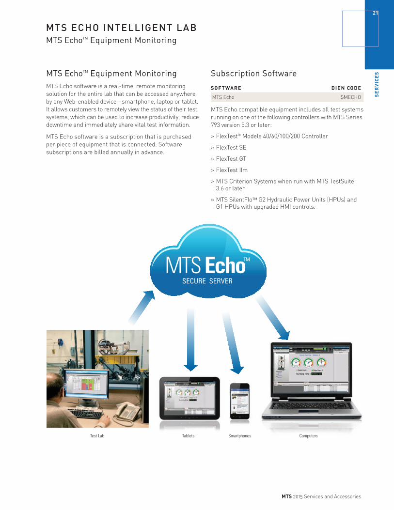
MTS Echo™
SECURE SERVER
MTS ECHO INTELLIGENT LABMTS EchoTM Equipment Monitoring
ComputersTablets SmartphonesTest Lab
MTS EchoTM Equipment MonitoringMTS Echo software is a real-time, remote monitoring solution for the entire lab that can be accessed anywhere by any Web-enabled device—smartphone, laptop or tablet. It allows customers to remotely view the status of their test systems, which can be used to increase productivity, reduce downtime and immediately share vital test information.
MTS Echo software is a subscription that is purchased per piece of equipment that is connected. Software subscriptions are billed annually in advance.
Subscription Software
SOFTWARE DIEN CODE
MTS Echo SMECHO
MTS Echo compatible equipment includes all test systems running on one of the following controllers with MTS Series 793 version 5.3 or later:
» FlexTest® Models 40/60/100/200 Controller
» FlexTest SE
» FlexTest GT
» FlexTest IIm
» MTS Criterion Systems when run with MTS TestSuite 3.6 or later
» MTS SilentFlo™ G2 Hydraulic Power Units (HPUs) and G1 HPUs with upgraded HMI controls.
SE
RV
ICE
S22
MTS 2015 Services and Accessories
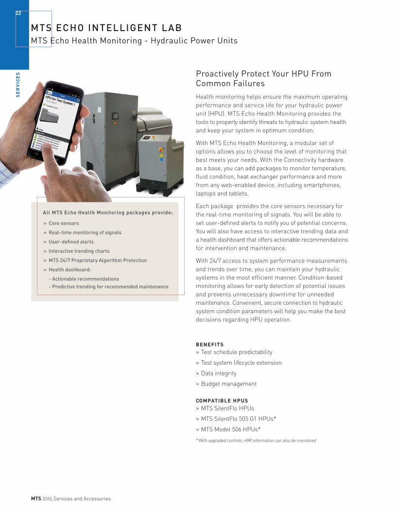
MTS ECHO INTELLIGENT LABMTS Echo Health Monitoring - Hydraulic Power Units
Proactively Protect Your HPU From Common FailuresHealth monitoring helps ensure the maximum operating performance and service life for your hydraulic power unit (HPU). MTS Echo Health Monitoring provides the tools to properly identify threats to hydraulic system health and keep your system in optimum condition.
With MTS Echo Health Monitoring, a modular set of options allows you to choose the level of monitoring that best meets your needs. With the Connectivity hardware as a base, you can add packages to monitor temperature, fluid condition, heat exchanger performance and more from any web-enabled device, including smartphones, laptops and tablets.
Each package provides the core sensors necessary for the real-time monitoring of signals. You will be able to set user-defined alerts to notify you of potential concerns. You will also have access to interactive trending data and a health dashboard that offers actionable recommendations for intervention and maintenance.
With 24/7 access to system performance measurements and trends over time, you can maintain your hydraulic systems in the most efficient manner. Condition-based monitoring allows for early detection of potential issues and prevents unnecessary downtime for unneeded maintenance. Convenient, secure connection to hydraulic system condition parameters will help you make the best decisions regarding HPU operation.
BENEFITS» Test schedule predictability
» Test system lifecycle extension
» Data integrity
» Budget management
COMPATIBLE HPUS» MTS SilentFlo HPUs
» MTS SilentFlo 505 G1 HPUs*
» MTS Model 506 HPUs*
* With upgraded controls, HMI information can also be monitored
All MTS Echo Health Monitoring packages provide:
» Core sensors
» Real-time monitoring of signals
» User-defined alerts
» Interactive trending charts
» MTS 24/7 Proprietary Algorithm Protection
» Health dashboard:
- Actionable recommendations - Predictive trending for recommended maintenance

SE
RV
ICE
S
23
MTS 2015 Services and Accessories
MTS Echo Health Monitoring
Standard Recommended Packages Protect your HPU investment and ongoing lab operations with 24/7 Health Monitoring of your HPU. Start with the recommended packages and add-on for extended protection.
TEMPERATURE PACKAGE
Monitor HPU temperatures for early detection of an over-temperature alarm or fault. These fault notifications can prevent unplanned downtime and minimize the risk of downstream damage. Maintaining a stable temperature is critical to the performance of your test system. Elevated temperature is also indicative of potential system failure.
FLUID CONTAMINATION PACKAGE
Hydraulic power units and servovalves can be damaged by fluid contaminated with particles that are larger than the clearance between lubricated surfaces. These hard particles create more wear contaminant by continually scraping off softer metals, like copper, to further accelerate component failures. This package will help identify conditions that may lead to motor shelling, pressure instability and servovalve instability.
HEAT EXCHANGER PACKAGE
This package monitors several parameters including changes in the thermal transfer over time and water consumption. Trending the water consumption can identify failed water solenoids or indicate when someone has forgotten to turn on the water supply, giving the operator time to turn on the supply and cool the hydraulic fluid to prevent an over temp shutdown. When combined with the temperature package, Heat Exchanger efficiency also can be tracked.
HPU Health Monitoring Packages Aligned to Common Failure Mode
HEALTH MONITORING OVER-TEMP HEAT EXCHANGER MOTOR & PUMP CATASTROPHEPACKAGES FAULTS FAILURES CONTAMINATION FAILURES PREVENTION DIEN CODE
Temperature Yes Yes, temperature No Wear & tear Medium SMEHMT Fouling
Contamination No Yes, water saturation Particulate contamination Wear & tear High SMEHMFC Water saturation Fouling
Heat Exchanger Yes Cooling System failures Water saturation No High SMEHMHX Heat Exchanger failures Cooling water flow
MTS ECHO INTELLIGENT LABMTS Echo Health Monitoring - Hydraulic Power Units

SE
RV
ICE
S24
MTS 2015 Services and Accessories
MTS Echo Health Monitoring
Additional Packages (Engineered-to-Order) Extend Fault protection with additional stand-alone packages.
POWER MONITORING PACKAGE
Expand your health protection by monitoring your HPU power, including 3- phase voltage, current and energy consumption. This package provides insight into HPU efficiency and enables early warning of pump or motor failures. This package can give you visibility to energy consumption and help improve energy management.
ACCUMULATOR PRE-CHARGE & FILTRATION PACKAGE
Manage hydraulic distribution by monitoring accumulators and filters. Remote monitoring will indicate which accumulators need charging so the hydraulic distribution system can readily manage flow demand. Monitoring filtration can help detect inadequacies that may lead to actuator scoring and potential component failure. The predictive trending and analytics provided in this package will optimize maintenance.
LEAK DETECTION PACKAGE
Protect your lab and the environment by monitoring for early detection of hose rupture, manifold failures and fitting leaks. Improve environmental health and safety while protecting against catastrophic hydraulic fluid loss.
HPU Health Monitoring Packages Aligned to Common Failure ModesHEALTH MONITORING OVER-TEMP MOTOR & PUMP CATASTROPHEPACKAGES FAULTS FAILURE MODES CONTAMINATION FAILURES PREVENTION DIEN CODE
Power No Energy usage No Early fault detection possible Low SMEHMP
Accumulator No Output pressure No No Medium SMEHMFAPre-charge and accumulatorsFilteration Clogged filters
Leak Detection No Hose rupture No No Low SMEHMLD Fittings Manifold failures
MTS ECHO INTELLIGENT LABMTS Echo Health Monitoring - Hydraulic Power Units

SE
RV
ICE
S
25
MTS 2015 Services and Accessories
WARRANTY COVERAGEOverview
MTS builds some of the most rugged and reliable testing equipment on the market. We also stand behind our products and services with extensive warranty options. In addition to providing standard warranty coverage on new equipment and service parts, MTS also offers optional extended warranties for equipment and components to help ensure your equipment is ready for testing when you need it.
Standard Warranty – EquipmentMTS warrants its equipment to be free from defects in material and workmanship under normal use, given proper installation and maintenance, for 12 months from the date of shipment of your product. Defective equipment may be repaired or replaced at MTS’ option.
Standard Warranty – Parts & ServicesWarranty periods for service products start with the product shipment from MTS. Replacement, exchange, remanufacture, or repair of a system component does not extend the warranty coverage of the entire system. Coverage on system components is as follows:
PURCHASED PARTS
Parts with a model number 12 months
Parts without a model number 90 days
EXCHANGE, REMANUFACTURE OR REPAIR PROGRAMS
Exchange 12 months
Remanufacture 12 months
Repair 90 days
OTHER SERVICES Factory calibrations 90 days
Field calibrations 90 days
Field service labor 90 days
Extended Warranty The Extended Warranty Program is available as part of a service contract designed to protect you from incurring unplanned material and labor expenses for repairing MTS equipment. It includes the following:
» Labor to troubleshoot and repair equipment
» Parts to repair equipment
» Exchange, remanufacture or repair as authorized by MTS
Extended Warranty Coverage The Extended Warranty Program is available for purchase as part of an Assured Maintenance Plan (AMP). Under this plan option, MTS will troubleshoot and repair or replace affected equipment and/or components during a 12-month plan period.
Extended Warranty coverage is grouped into three classes:
» Controllers (number of control channels)
» Load frames and actuators
» Hydraulic power units
» It is easy to add coverage for your entire laboratory, or for only a portion of your MTS equipment.
Extended Warranty Exclusions» MTS reserves the right to exclude any product from
coverage. Please contact your sales engineer for complete details of product eligibility.
» Upgrades and updates required due to obsolete hardware and software cannot be part of an Extended Warranty Program.
» Hydraulic fluid is not covered under an Extended Warranty Program.
» MTS offers End-of-Life product communications as needed to assist in your equipment planning.
MTS reserves the right to change products, services, and prices without notice.
If your system or product is more than 3 years old, a condition assessment may need to be performed by MTS to confirm availability. MTS serial number for each covered item must be recorded within the AMP Extended Warranty contract.
MTS reserves the right reject claims for warranty where it is determined that failure is caused by Buyer – or third party made – modifications, improper maintenance, misuse, misapplication, improper or incomplete qualification, abuse of the Product, damage caused by connections, interfacing or use in unforeseen or unintended environment. These conditions will render warranties null and void.
SE
RV
ICE
S26
MTS 2015 Services and Accessories
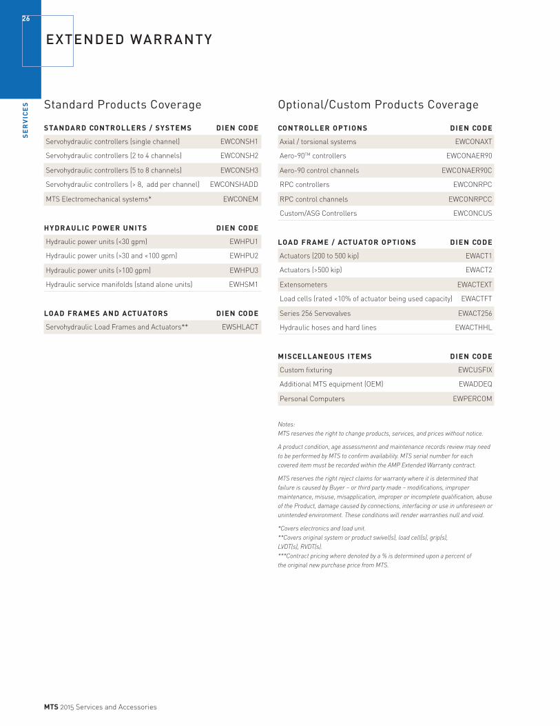
EXTENDED WARRANTY
Standard Products Coverage
STANDARD CONTROLLERS / SYSTEMS DIEN CODE
Servohydraulic controllers (single channel) EWCONSH1
Servohydraulic controllers (2 to 4 channels) EWCONSH2
Servohydraulic controllers (5 to 8 channels) EWCONSH3
Servohydraulic controllers (> 8, add per channel) EWCONSHADD
MTS Electromechanical systems* EWCONEM
HYDRAULIC POWER UNITS DIEN CODE
Hydraulic power units (<30 gpm) EWHPU1
Hydraulic power units (>30 and <100 gpm) EWHPU2
Hydraulic power units (>100 gpm) EWHPU3
Hydraulic service manifolds (stand alone units) EWHSM1
LOAD FRAMES AND ACTUATORS DIEN CODE
Servohydraulic Load Frames and Actuators** EWSHLACT
Optional/Custom Products Coverage
CONTROLLER OPTIONS DIEN CODE
Axial / torsional systems EWCONAXT
Aero-90TM controllers EWCONAER90
Aero-90 control channels EWCONAER90C
RPC controllers EWCONRPC
RPC control channels EWCONRPCC
Custom/ASG Controllers EWCONCUS
LOAD FRAME / ACTUATOR OPTIONS DIEN CODE
Actuators (200 to 500 kip) EWACT1
Actuators (>500 kip) EWACT2
Extensometers EWACTEXT
Load cells (rated <10% of actuator being used capacity) EWACTFT
Series 256 Servovalves EWACT256
Hydraulic hoses and hard lines EWACTHHL
MISCELLANEOUS ITEMS DIEN CODE
Custom fixturing EWCUSFIX
Additional MTS equipment (OEM) EWADDEQ
Personal Computers EWPERCOM
Notes: MTS reserves the right to change products, services, and prices without notice.
A product condition, age assessmennt and maintenance records review may need to be performed by MTS to confirm availability. MTS serial number for each covered item must be recorded within the AMP Extended Warranty contract.
MTS reserves the right reject claims for warranty where it is determined that failure is caused by Buyer – or third party made – modifications, improper maintenance, misuse, misapplication, improper or incomplete qualification, abuse of the Product, damage caused by connections, interfacing or use in unforeseen or unintended environment. These conditions will render warranties null and void.
*Covers electronics and load unit. **Covers original system or product swivel(s), load cell(s), grip(s), LVDT(s), RVDT(s). ***Contract pricing where denoted by a % is determined upon a percent of the original new purchase price from MTS.
LO
AD
CE
LL
S
27
MTS 2015 Services and Accessories
LOAD CELLS FOR SERVOHYDRAULIC SYSTEMS
Axial, Dynamic Fatigue-Rated Load Cells MTS axial, dynamic fatigue-rated load cells reduce errors caused by extraneous side loads or loading changes caused by geometry shifts in the specimen. Their monolithic design incorporates high axial stiffness. They are made from aircraft-quality military specification materials specially heat-treated to ensure uniform hardness and minimize distortion. Calibration, cables, and attachment kits are sold separately.
FEATURES AND BENEFITS» Dynamic performance—low deflection and high stiffness
give you better dynamic performance
» High output—provides you with excellent resolution and reading accuracy
» Radially oriented beams—enable the unit to resist off-axis loads and moments for greater accuracy
» High degree of component concentricity and parallelism—provide you with greater accuracy during your test setup
» Unique proprietary wiring technique used on the bridge allows for minimal susceptibility to stray magnetic fields
Axial, Low Capacity Load CellsMODEL UNITS FORCE CAPACITY THREAD SIZE PART NUMBER
661.09A-20 US Customary 2 lbf 0.25 in - 28 051-340-601
661.09B-20 Metric 10 N M6 x 1 051-340-602
661.09A-21 US Customary 22 lbf 0.25 in - 28 051-340-603
661.09B-21 Metric 100 N M6 x 1 051-340-604 Axial, Dynamic Fatigue-Rated Load Cells661.11A-01 US Customary 50 lbf 0.25 in - 28 050-781-901
661.11B-01 Metric 250 N M6 x 1 050-781-905
661.11A-02 US Customary 100 lbf 0.25 in - 28 050-781-902
661.11B-02 Metric 500 N M6 x 1 050-781-906
661.18E-01 US Customary 220 lbf 0.50 in - 20 050-459-901
661.18F-01 Metric 1 kN M12 x 1.25 050-459-902
661.18E-02 US Customary 550 lbf 0.50 in - 20 050-459-903
661.18F-02 Metric 2.5 kN M12 x 1.25 050-459-904
661.19E-01 US Customary 1.1 kip 0.50 in - 20 045-438-101
661.19F-01 Metric 5 kN M12 x 1.25 045-438-102
661.19E-02 US Customary 2 kip 0.50 in - 20 045-438-103
661.19F-02 Metric 10 kN M12 x 1.25 045-438-104
661.19E-03 US Customary 3 kip 0.50 in - 20 045-438-105
661.19F-03 Metric 15 kN M12 x 1.25 045-438-106
661.19E-04 US Customary 5 kip 0.50 in - 20 045-438-107
661.19F-04 Metric 25 kN M12 x 1.25 045-438-108
661.20E-01 US Customary 5 kip 1.00 in - 14 045-430-001
661.20F-01 Metric 25 kN M27 x 2 045-430-004
661.20E-02 US Customary 11 kip 1.00 in - 14 045-430-002
661.20F-02 Metric 50 kN M27 x 2 045-430-005
661.20E-03 US Customary 22 kip 1.00 in - 14 045-430-003
661.20F-03 Metric 100 kN M27 x 2 045-430-006
» Interchangeable—simple mounting makes installation and changing easy
» Ability to stack load cells to test smaller/larger specimens in same load frame
» Large choice of sizes—increases versatility
» Dual bridge options available—contact MTS
These load cells are fatigue rated.
LO
AD
CE
LL
S28
MTS 2015 Services and Accessories
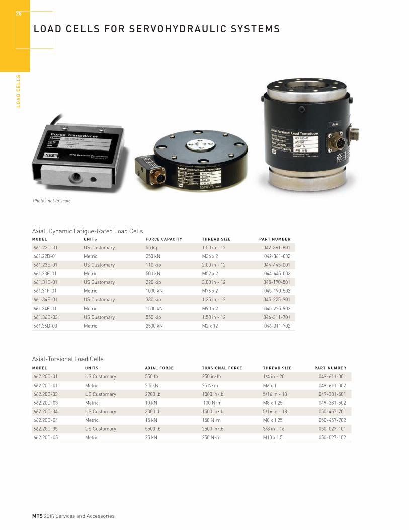
LOAD CELLS FOR SERVOHYDRAULIC SYSTEMS
Axial, Dynamic Fatigue-Rated Load Cells MODEL UNITS FORCE CAPACITY THREAD SIZE PART NUMBER
661.22C-01 US Customary 55 kip 1.50 in - 12 042-361-801
661.22D-01 Metric 250 kN M36 x 2 042-361-802
661.23E-01 US Customary 110 kip 2.00 in - 12 044-445-001
661.23F-01 Metric 500 kN M52 x 2 044-445-002
661.31E-01 US Customary 220 kip 3.00 in - 12 045-190-501
661.31F-01 Metric 1000 kN M76 x 2 045-190-502
661.34E-01 US Customary 330 kip 1.25 in - 12 045-225-901
661.34F-01 Metric 1500 kN M90 x 2 045-225-902
661.36C-03 US Customary 550 kip 1.50 in - 12 046-311-701
661.36D-03 Metric 2500 kN M2 x 12 046-311-702
Axial-Torsional Load CellsMODEL UNITS AXIAL FORCE TORSIONAL FORCE THREAD SIZE PART NUMBER
662.20C-01 US Customary 550 lb 250 in.lb 1/4 in - 20 049-611-001
662.20D-01 Metric 2.5 kN 25 N.m M6 x 1 049-611-002
662.20C-03 US Customary 2200 lb 1000 in.lb 5/16 in - 18 049-381-501
662.20D-03 Metric 10 kN 100 N.m M8 x 1.25 049-381-502
662.20C-04 US Customary 3300 lb 1500 in.lb 5/16 in - 18 050-457-701
662.20D-04 Metric 15 kN 150 N.m M8 x 1.25 050-457-702
662.20C-05 US Customary 5500 lb 2500 in.lb 3/8 in - 16 050-027-101
662.20D-05 Metric 25 kN 250 N.m M10 x 1.5 050-027-102
Photos not to scale

LO
AD
CE
LL
S
29
MTS 2015 Services and Accessories
LOAD CELLS FOR SERVOHYDRAULIC SYSTEMS
Axial, Dynamic Fatigue-Rated Load Cells with Integrated TEDS
MODEL UNITS FORCE CAPACITY THREAD SIZE PART NUMBER
661.11H-01 Metric 250 N M6 x 1 057-117-901
661.11H-02 Metric 500 N M6 x 1 057-117-902
661.11H-03 Metric 1000 N M6 x 1 057-117-903
661.18H-01 Metric 1000 N M12 x 1.25 057-118-001
661.18H-02 Metric 2.5 kN M12 x 1.25 057-118-002
661.19H-01 Metric 5 kN M12 x 1.25 057-118-101
661.19H-02 Metric 10 kN M12 x 1.25 057-118-102
661.19H-03 Metric 15 kN M12 x 1.25 057-118-103
661.19H-04 Metric 25 kN M12 x 1.25 057-118-104
661.20H-02 Metric 50 kN M27 x 2 057-118-201
661.20H-03 Metric 100 kN M27 x 2 057-118-202
661.22H-01 Metric 250 kN M36 x 2 057-263-701
661.23H-01 Metric 500 kN M52 x 2 057-263-801
Axial-Torsional Load Cells with Integrated TEDS MODEL UNITS AXIAL FORCE TORSIONAL FORCE THREAD SIZE PART NUMBER
662.20H-01 Metric 2.5 kN 25 N.m M6 x 1 057-202-601
662.20H-03 Metric 10 kN 100 N.m M8 x 1.25 057-202-701
662.20H-04 Metric 15 kN 150 N.m M8 x 1.25 057-202-702
662.20H-05 Metric 25 kN 250 N.m M10 x 1.5 057-202-801

LO
AD
CE
LL
S30
MTS 2015 Services and Accessories
LOAD CELLS FOR ELECTROMECHANICAL SYSTEMSInsight and Insight Renew
Load Cells Highly accurate MTS load cells for electromechanical test systems are designed to offer world-class stiffness, stability, and linearity. They provide overload and side load protection and are designed with built-in shunt resistors to facilitate regular verification of accuracy using calibration routines featured in MTS software. To increase efficiency and reduce potential operator error, these load cells feature TEDS (Transducer Electronic Data Sheets) self-identification capabilities that follow the recently adopted IEEE 1451.4 standard.
Insight Load Cells with TEDS Self ID TYPE UNIT FORCE CAPACITY ATTACHMENT PART NUMBER
S-Beam Metric 500 N (110 lbf) M6x1 056-932-701
S-Beam Metric 50 N (10 lbf) M6x1 056-932-604
S-Beam Metric 5 N (1 lbf) M6x1 056-932-601
S-Beam Metric 250 N (50 lbf) M6x1 056-932-606
S-Beam Metric 25 N ( 5 lbf) M6x1 056-932-603
S-Beam Metric 2 kN (450 lbf) M6x1 056-932-703
S-Beam Metric 100 N (20 lbf) M6x1 056-932-605
S-Beam Metric 10 N (2 lbf) M6x1 056-932-602
S-Beam Metric 1 kN (220 lbf) M6x1 056-932-702
Low Profile Metric 500 N (110 lbf) M6x1 056-932-803
Low Profile Metric 250 N (50 lbf) M6x1 056-932-802
Low Profile Metric 125 N (25 lbf) M6x1 056-932-801
Low Profile Metric 10 kN (2,200 lbf) M12x1.25 056-932-904
Low Profile Metric 5 kN (1,100 lbf) M12x1.25 056-932-903
Low Profile Metric 2.5 kN (550 lbf) M12x1.25 056-932-902
Low Profile Metric 1 kN (225 lbf) M12x1.25 056-932-901
Low Profile Metric 30 kN (6,600 lbf) M12x1.25 056-932-905
Low Profile Metric 50 kN (11,000 lbf) M16x1.5 056-933-201
Low Profile Metric 100 kN (22,500 lbf) M27x2 056-933-001
Low Profile Metric 150 kN (33,750 lbf) M27x2 056-933-002
Low Profile Metric 200 kN (45,000 lbf) M36x2 056-933-301
Low Profile Metric 300 kN (67,500 lbf) M36x2 056-933-101

LO
AD
CE
LL
S
31
MTS 2015 Services and Accessories
LOAD CELLS FOR ELECTRODYNAMIC SYSTEMS
Axial, Dynamic Fatigue-Rated System Load Cells with Built-in AccelerometerMTS axial, dynamic fatigue-rated system load cells reduce errors caused by extraneous side loads or loading changes caused by geometry shifts in the specimen. A built-in accelerometer interfaces with the MTS Acumen system to provide inertial compensation when mounted on the actuator. Their monolithic design incorporates high axial stiffness and they are made from aircraft-quality military specification materials specially heat-treated to ensure uniform hardness and minimize distortion. Designed for the MTS Acumen electrodynamic test systems, these load cells can be mounted either on the actuator or the T-slot table.
FEATURES AND BENEFITS
» Dynamic performance—low deflection and high stiffness give you better dynamic performance.
» High output—provides you with excellent resolution and reading accuracy.
» Accelerometer—Integrated acceleration sensor enables load cell to be mounted on moving actuator.
» Piloted load cell —simplifies load cell installation and minimizes the need for a separate alignment fixture.
» Radially oriented beams—enable the unit to resist off-axis loads and moments for greater accuracy.
» High degree of component concentricity and parallelism—provide you with greater accuracy during your test setup.
» Unique proprietary wiring technique used on the bridge allows for minimal susceptibility to stray magnetic fields.
» Interchangeable—simple mounting makes installation and changing easy.
» Ability to stack lower force transducers to test smaller specimens in same load frame.
» Integrated TEDS.
Axial, Dynamic Fatigue-Rated Lower Force Load Cell KitsMTS axial, dynamic fatigue-rated lower force load cells reduce errors caused by extraneous side loads or loading changes caused by geometry shifts in the specimen. Their monolithic design incorporates high axial stiffness and they are made from aircraft-quality military specification materials specially heat-treated to ensure uniform hardness and minimize distortion. These compact load cells mount easily to the MTS Acumen system load cells.
FEATURES AND BENEFITS
» Dynamic performance—low deflection and high stiffness give you better dynamic performance.
» High output—provides you with excellent resolution and reading accuracy.
» Radially oriented beams—enable the unit to resist off-axis loads and moments for greater accuracy.
» High degree of component concentricity and parallelism— provide you with greater accuracy during your test setup.
» Unique proprietary wiring technique used on the bridge allows for minimal susceptibility to stray magnetic fields.
» Interchangeable—simple mounting makes installation and changing easy.
» Easily mounted to electrodynamic system load cells.
» Integrated TEDS.
FACTORY KIT CALIBRATED LOAD CELL FORCE THREAD PART KIT PART MODEL UNITS CAPACITY SIZE NUMBER* NUMBER*
661.18SE-01 Metric 1.5 kN M6 x 1 057-560-101 057-560-106
661.18SE-02 Metric 3 kN M6 x 1 057-560-102 057-560-107
*Kits include load cell, mounting hardware, CD and protective case
FACTORY KIT CALIBRATED LOAD CELL FORCE THREAD PART KIT PART MODEL UNITS CAPACITY SIZE NUMBER* NUMBER*
661.11H-04 Metric 125 N M6 x 1 057-560-105 057-560-110
661.11H-01 Metric 250 N M6 x 1 057-560-104 057-560-109
661.11H-02 Metric 500 N M6 x 1 057-560-103 057-560-108
*Kits include load cell, mounting hardware and spanner wrench
LO
AD
CE
LL
S32
MTS 2015 Services and Accessories
LOAD CELL ADAPTERS
Adapter Introduction MTS is pleased to offer a wide variety of load cell adapters to meet all of your special needs. Our adapters are made to the best possible specifications and adhere to the industry standards. In many cases, we offer more than one type of material so you may choose the lightweight aluminum or the heavy duty steel adapters. If there is an adapter you would like that you do not see listed, contact your sales engineer.
Tandem Piggyback FROM THREAD SIZE TO THREAD SIZE PART NUMBER
M6 x 1 M16 x 1.5 056-871-102
M12 x 1.25 M27 x 2 056-871-106
M12 x 1.25 M36 x 2 056-871-107
M12 x 1.25 M16 x 1.5 056-871-105
M16 x 1.5 M27 x 2 056-871-108
M16 x 1.5 M36 x 2 056-871-109
M27 x 2 M36 x 2 056-871-110
M6 x 1 M12 x 1.25 056-871-101
M6 x 1 M36 x 2 056-871-104
M6 x 1 M27 x 2 056-871-103
Piggyback FROM THREAD SIZE TO THREAD SIZE PART NUMBER
0.5 in - 20 1 in - 14 100-082-366
0.25 in - 28 1 in - 14 100-082-361
0.25 in - 28 1.5 in - 12 100-082-608
0.25 in - 28 0.5 in - 20 100-082-319
M16 x 1.5 M24 x 1.5 100-105-984
1 in - 14 1.5 in - 12 100-082-598
M12 x 1.25 M6 x 1 100-093-064
1 in - 14 1 in - 14 100-179-743
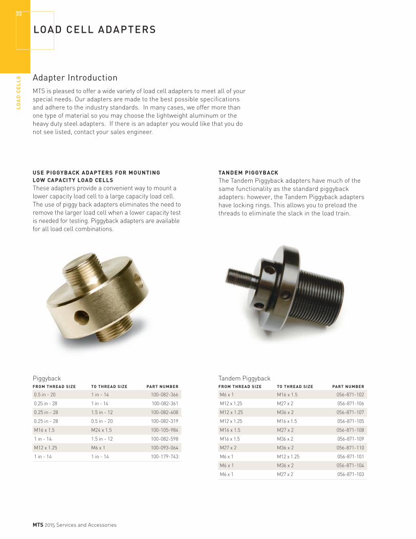
USE PIGGYBACK ADAPTERS FOR MOUNTING LOW CAPACITY LOAD CELLSThese adapters provide a convenient way to mount a lower capacity load cell to a large capacity load cell. The use of piggy back adapters eliminates the need to remove the larger load cell when a lower capacity test is needed for testing. Piggyback adapters are available for all load cell combinations.
TANDEM PIGGYBACKThe Tandem Piggyback adapters have much of the same functionality as the standard piggyback adapters: however, the Tandem Piggyback adapters have locking rings. This allows you to preload the threads to eliminate the slack in the load train.

LO
AD
CE
LL
S
33
MTS 2015 Services and Accessories
CLEVIS PIN With a clevis pin, you can easily and quickly change out your grips and fixtures without diminishing the force of your test. MTS offers a wide variety of clevis pin devices that meet the industry standards. Many of these adapters are available in steel or aluminum.
CONVERSION ADAPTER We offer a wide variety of conversion adapters to help you quickly change from one type or style of clevis adapter to another without the costs associated with a full adapter.
Clevis Pin CONNECTION PIN CLEVIS PART THREAD SIZE TYPE DIAMETER DIAMETER NUMBER
M27 x 2 Df 0.5 in 1.25 in 100-140-862
M12 x 1.25 Cf 0.25 in 0.625 in 100-140-788
M12 x 1.25 Df 0.5 in 1.25 in 100-140-546
1 in - 14 Df 0.5 in 1.25 in 100-088-645
M16 x 1.5 Df 0.5 in 1.25 in 100-092-928
0.25 in - 28 Df 0.5 in 1.25 in 100-092-552
M24 x 1.5 Df 0.5 in 1.25 in 100-092-905
M36 x 2 Df 0.5 in 1.25 in 100-092-937
0.5 in - 20 Df 0.5 in 1.25 in 100-088-650
M6 x 1 Df 0.5 in 1.25 in 100-092-919
M12 x 1.25 Bf 0.187 in 0.5 in 100-093-049
M6 x 1 Bf 0.187 in 0.5 in 100-092-923
0.25 in - 28 Bf 0.187 in 0.5 in 100-092-914
M6 x 1 Cf 0.25 in 0.625 in 100-092-910
0.25 in - 28 Cf 0.25 in 0.625 in 100-092-547
Conversion Adapter CLEVIS PIN THREAD SIZE CONNECTION TYPE PART NUMBER
30 mm 15f Male to Female 100-093-030
0.5 in - 20 15f Male to Female 100-093-001
1.25 in - 12 30f Male to Female 100-092-991
0.625 in - 18 15f Male to Female 100-092-996
1.25 in Cf Male to Female 100-092-880
0.25 in - 28 Df Male to Female 100-081-395
1.50 in - 12 Df Male to Female 100-082-558
0.5 in - 20 Cf Male to Female 100-081-868
0.5 in - 20 Bf Male to Female 100-081-862
1 in - 14 Cf Male to Female 100-081-873
Insight Load cell Mounting Kits THREAD SIZE WORKSTATIONS PART NUMBER
M36 x 2 200 & 300 056-904-512
M27 x 2 200 & 300 056-904-511
M16 x 1.5 200 & 300 056-904-510
M27 x 2 100 & 150 056-904-509
M16 x 1.5 100 & 150 056-904-508
M12 x 1.25 100 & 150 056-904-507
M16 x 1.5 30 & 50 056-904-506
M12 x 1.25 30 & 50 056-904-505
M6 x 1 30 & 50 056-904-504
M12 x 1.25 5 & 10 056-904-503
M6 x 1 5 & 10 056-904-502
M6 x 1 1 & 2 056-904-501
LOAD CELL ADAPTERS

EX
TE
NS
OM
ET
ER
S34
MTS 2015 Services and Accessories
MTS EXTENSOMETERS
Accuracy Is the KeyA material test system requires the capability to measure values such as load, strain, displacement, and crack length; and to control their rate of change with accuracy.
Many variables, such as load, can be measured from the load train rather than directly from the specimen. However, variables like strain or crack length are most accurately determined when measured directly from a specimen by direct contact or non-contacting extensometers.
VERSATILITYMTS has the most extensive and comprehensive line of extensometers available anywhere. You can choose from models that operate precisely under a broad spectrum of conditions, including:
» Thermal environments up to 2300°C (4100°F)
» Humidity up to condensation
» Inert or corrosive mediums, liquids, and gases
» Vacuum to high pressures
» Nuclear radiation
HIGH PERFORMANCE, HIGH QUALITYMTS extensometers provide superior performance in linearity, repeatability, hysteresis, low activation force, and ease of use. Here’s why:
» They’re engineered to last.
» MTS’ cross-flexure system ensures that the strain gages are always subjected to true center point bending, and the same force, time after time.
» Built-in overtravel protection lets you repeatedly get accurate data in tensile and compressive modes, through specimen failure.
» Zero set pin or zero stop provides a quick, accurate setup that is repeatable.
» Replaceable knife edges are designed for round or flat specimens, for normal or tough applications.
» Our experienced application and support staff are dedicated to helping you meet your testing challenges.
THE RELIABLE CHOICE We offer a complete line of accessories and options to enhance our extensometers’ capability, flexibility, and usefulness. And we’re constantly developing new models and enhancements.
If you are unable to find an exact fit for your requirements, please contact us.
MTS has the broadest selection of extensometry in the world.
EX
TE
NS
OM
ET
ER
S
35
MTS 2015 Services and Accessories
EXTENSOMETER APPLICATION INDEX
Use this helpful index to determine which extensometers are best suited for your application. If the extensometer
APPLICATION EXTENSOMETER OPTIONS SEE PAGES METALS
Tensile (ASTM E8) 632.13/.24 & 634.11/.12/.25/.28/.31 37, 38, 40, 41 Compression (ASTM E9) 632.13/.26/.27 & 634.11/.12/.31 37, 38, 39, 41 KIC - Fracture Toughness (ASTM) 632.02 ASTM Standard; 632.03 MTS Enhanced; 632.65 (High Temperature) 48, 49 Pre-Cracking (ASTM E399) 632.05 (High Frequency) 48 JIC (ASTM E813) 632.03 with Long Travel Option 49 Crack Growth - Bend (ASTM E399) 632.03 49 Fatigue Crack Growth (ASTM E647) 632.03 with Long Travel Option; 632.05 (High Frequency) 48, 49 High Cycle Fatigue 632.27 (Low Strain) 39 Low Cycle Fatigue (ASTM E606) 632.13/.18/.19/.20 & 634.11/.12/.31 & 632.50/.51/.53/.54 37, 38, 41, 43, 44, 45 Low Cycle Fatigue (High Temp) 632.50/.51/.52 44, (please call for .52) Low Cycle Fatigue (High Temp) 632.53/.54 45
ADVANCED MATERIALS
Bend (MIL SPEC 1942, JIS 1601R) 632.06 50 Tensile/Compression 632.26 38 High Temperature (CMC’s MMC’s) 632.5X 44, 45 Ultra High Temperature T/C 632.59 please call Ultra High Temperature Bend 632.70 please call
COMPOSITES
Tensile (ASTM D3039) 632.17/.85 & 634.11/.31 37, 40, 46 Compression (ASTM D695) 632.17 & 634.11/.31 37, 40, 46 ±45° Shear Test (ASTM D3518) 632.17 & 634.11/.31 37, 40, 46 Flexure (ASTM D790) 632.06 & 634.11/.31 37, 40, 50 Tension/Tension Fatigue (ASTM D3479) 632.17/.85 & 634.11/.31 37, 40, 46
PLASTICS
Tensile (ASTM D638) 632.17/.24/.85 & 634.12/.25/.31 & LX 500/1500 37, 40, 41, 45, 47
ROCK MECHANICS
Triaxial Comp. Strength (ASTM D2664) 632.90/.92 please call Triaxial Creep (ASTM D4406) 632.90/.92 please call
BIO-MATERIALS 632.29/.32/.79 & 634.11/.12/.25/.31 & LX 500 37, 40, 41, 42, 47AXIAL/TORSIONAL 632.68/.80 please call
HIGH TEMPERATURE
Air Cooled 632.53/.54 45 Water Cooled 632.51/.59/.68 44, (please call for .59/.68) Uncooled 632.53/.54/.70 45 Hostile Environments 632.10 & LX 500/1500 47
FRACTURE MECHANICS
Fracture Toughness 632.02/.03; 632.65 48, 48 Pre-Cracking 632.05 (High Frequency) 48
BEND
Displacement 632.06 50 Crack Growth 632.03 49 High Temperature 632.70 please call
FATIGUE
Crack Growth 632.03 with Long Travel Option; 632.05 & 632.65 48, 49 High Cycle 632.27 (Low Strain) 39 Low Cycle 632.13/.18/.19/.20 & 634.11/.12/.31 37, 38, 41, 43 Low Cycle (High Temp) 632.41/.42 & 632.50/.51/.53/.54 44, 45
TENSILE/COMPRESSION TESTING
Tensile 632.13/.24 & 634.11/.12/.25/.28/.31 37, 38, 40, 41 Compression 632.13/.26/.27 & 634.12/.25/.31 37, 38, 39, 40, 41 Poisson’s Ratio 632.18/.19/.20/.23/.85 & 634.12/.25/.31 37, 39, 40, 41, 43, 46 Elastic Limit 632.26/.27/.29 38, 39, 42
listed is in blue, it is not shown in this catalog. Please contact us for more information.

EX
TE
NS
OM
ET
ER
S36
MTS 2015 Services and Accessories
EXTENSOMETER FUNCTIONAL INDEX
DYNAMIC MODELS (TENSION/COMPRESSION)
Metric Units US CustomaryMODEL GAGE MODEL GAGE NUMBER LENGTH STRAIN (TRAVEL) NUMBER LENGTH STRAIN (TRAVEL) SEE PAGE
632.29F-20 3 mm ±8% (±0.24 mm) 632.29E-20 0.12 in ±8% (±0.0096 in) 42
632.29F-30 5 mm -10%/+30% (-0.5 mm/+1.5 mm) 632.29E-30 0.2 in -10%/+30% (-0.02 in/+0.06 in) 42
632.29F-30 6 mm ±4% (±0.24 mm) 632.29E-30 0.24 in ±4% (±0.0096 in) 42
632.26F-3X 8 mm ±6% (±0.48 mm) 632.26E-3X 0.3 in ±6% (±0.018 in) 38
632.26F-2X 8 mm ±15% (±1.2 mm) 632.26E-2X 0.3 in ±15% (±0.045 in) 38
632.13F-2X 10 mm ±15% (±1.5 mm) 632.13E-2X 0.5 in ±15% (±0.075 in) 38
632.26F-4X 12 mm ±9% (±1.1 mm) 632.26E-4X 0.5 in ±9% (±0.045 in) 38
632.27F-3X 25 mm ±2% (±0.5 mm) 632.27E-3X 1.0 in ±2% (±0.02 in) 39
632.27F-2X 25 mm ±4% (±1.0 mm) 632.27E-2X 1.0 in ±4% (±0.04 in) 39
634.11F-2X 25 mm +20%/-10% (+5 mm/-2.5 mm) 634.11E-2X 1.0 in +20%/-10% (+0.2 in/-0.1 in) 37
634.12F-2X 25 mm +50%/-10% (+12.5 mm/-2.5 mm) 634.12E-2X 1.0 in +50%/-10% (+0.5 in/-0.1 in) 37
634.25F-2X 50 mm +50%/-10% (+25 mm/-5 mm) 634.25E-2X 2.0 in +50%/-10% (+1.0 in/-0.2 in) 40
634.31F-2X 10-50 mm variable (+4 mm/-2 mm) 634.31E-2X 0.5-2.0 in variable (+0.2 in/-0.1 in) 41
MONOTONIC MODELS (TENSION ONLY)
Metric Units US CustomaryMODEL GAGE MODEL GAGE NUMBER LENGTH STRAIN (TRAVEL) NUMBER LENGTH STRAIN (TRAVEL) SEE PAGE
634.11F-5X 25 mm +20% (+5 mm) 632.11E-5X 1.0 in +20% (+0.2 in) 37
634.12F-5X 25 mm +50% (+12.5 mm) 632.12E-5X 1.0 in +50% (+0.5 in) 37
632.24F-50 25 mm +100% (+25 mm) 632.24E-50 1.0 in +100% (+1.0 in) 40
634.25F-5X 50 mm +50% (+25 mm) 634.25E-5X 2.0 in +50% (+1.0 in) 40
634.28F-24 50 mm +100% (+50 mm) 634.28E-24 2.0 in +100% (+2.0 in) 40
Axial Extensometers
Other ExtensometersAveraging models page 46
Biaxial models page 46
Diametral models page 43
Displacement gages pages 48-50
General applications pages 37-41
High Temperature models page 43-45
Immersible models page 42
Laser models page 47
Miniature models page 42
Unique Applications page 51
Extensometer Accessories pages 52-54
Note: All extensometers require cables; please see cable section to select the correct cable.

EX
TE
NS
OM
ET
ER
S
37
MTS 2015 Services and Accessories
GENERAL APPLICATIONS
Exceptional Accuracy
Meets or exceeds requirements for calibration according to ASTM E83 Class B1 and ISO 9513 Class 0.5 standards.
Metric Units GAGE NON- MODEL LENGTH TRAVEL (STRAIN) LINEARITY HYSTERESIS HEIGHT LENGTH
634.11F-2X 25 mm ±0.05 +5 mm/-2.5 mm (+20%/-10%) 0.15% 0.10% 33.0 mm 73.4 mm
634.11F-5X 25 mm ±0.05 +5 mm (+20%) 0.15% 0.10% 33.0 mm 59.9 mm
634.12F-2X 25 mm ±0.05 +12.5 mm/-2.5 mm (+50%/-10%) 0.25% 0.10% 33.0 mm 82.8 mm
634.12F-5X 25 mm ±0.05 +12.5 mm (+50%) 0.25% 0.10% 33.0 mm 82.8 mm
TEMPERATURE ACTIVATION MODEL MIN/MAX FORCE PART NUMBER
634.11F-21 -269°C/65°C* 35 g 052-251-807
634.11F-24 -85°C/120°C* 35 g 052-251-808
634.11F-25 -100°C/175°C 45 g 052-251-809
634.11F-51 -269°C/65°C* 35 g 052-251-810
634.11F-54 -85°C/120°C* 35 g 052-251-811
634.11F-55 -100°C/175°C 45 g 052-251-812
US Customary GAGE NON- MODEL LENGTH TRAVEL (STRAIN) LINEARITY HYSTERESIS HEIGHT LENGTH
634.11E-2X 1.000 in ±0.002 +0.2 in/-0.10 in (+20%/-10%) 0.15% 0.10% 1.30 in 2.89 in
634.11E-5X 1.000 in ±0.002 +0.2 (+20%) 0.15% 0.10% 1.30 in 2.36 in
634.12E-2X 1.000 in ±0.002 +0.50 in/-0.10 in (+50%/-10%) 0.25% 0.10% 1.30 in 3.26 in
634.12E-5X 1.000 in ±0.002 +0.5 (+50%) 0.25% 0.10% 1.30 in 3.26 in
TEMPERATURE ACTIVATION MODEL MIN/MAX FORCE PART NUMBER
634.12F-21 -269°C/65°C* 45 g 051-191-507
634.12F-24 -85°C/120°C* 45 g 051-191-508
634.12F-25 -100°C/175°C 55 g 051-191-509
634.12F-51 -269°C/65°C* 45 g 051-191-510
634.12F-54 -85°C/120°C* 45 g 051-191-511
634.12F-55 -100°C/175°C 55 g 051-191-512
TEMPERATURE ACTIVATION MODEL MIN/MAX FORCE PART NUMBER
634.11E-21 -452°F/150°F* 35 g 052-251-801
634.11E-24 -120°F/250°F* 35 g 052-251-802
634.11E-25 -150°F/350°F 45 g 052-251-803
634.11E-51 -452°F/150°F* 35 g 052-251-804
634.11E-54 -120°F/250°F* 35 g 052-251-805
634.11E-55 -150°F/350°F 45 g 052-251-806
TEMPERATURE ACTIVATION MODEL MIN/MAX FORCE PART NUMBER
634.12E-21 -452°F/150°F* 45 g 051-191-501
634.12E-24 -120°F/250°F* 45 g 051-191-502
634.12E-25 -150°F/350°F 55 g 051-191-503
634.12E-51 -452°F/150°F* 45 g 051-191-504
634.12E-54 -120°F/250°F* 45 g 051-191-505
634.12E-55 -150°F/350°F 55 g 051-191-506
*These units may be used at 25°C (50°F) higher than the listed max temperature, but only for durations less than 24 hours.
These axial extensometers are ideal for a variety of applications. They include knife edges and patented quick attachment fixtures for both flat and round specimens, as well as the standard elastic attachment kit.

EX
TE
NS
OM
ET
ER
S38
MTS 2015 Services and Accessories
GENERAL APPLICATIONS
Exceptional Accuracy
Meets or exceeds requirements for calibration according to ASTM E83 Class B1 and ISO 9513 Class 0.5 standards.
Model 632.13 Axial Extensometer (shown with Flat Specimen Quick Attach Kit)
Model 632.26 Axial Extensometer (shown with Quick Attach Kit
Metric Units GAGE NON- MODEL LENGTH TRAVEL (STRAIN) LINEARITY HYSTERESIS HEIGHT LENGTH
632.26F-3X 8 mm ±0.48 mm (±6%) 0.20% 0.10% 17.5 mm 44.5 mm
632.26F-2X 8 mm ±1.20 mm (±15%) 0.20% 0.10% 17.5 mm 44.5 mm
632.13F-2X 10 mm ±1.50 mm (±15%) 0.15% 0.10% 32.8 mm 41.1 mm
632.26F-4X 12 mm ±1.08 mm (±9%) 0.20% 0.10% 18.8 mm 44.5 mm
TEMPERATURE ACTIVATION MODEL MIN/MAX* FORCE PART NUMBER
632.26F-30 -100°C/150°C 40 g 047-401-810
632.26F-31 - 269°C/65°C 40 g 047-401-811
632.26F-33 - 100°C/175°C 60 g 047-401-812
632.26F-20 -100°C/150°C 40 g 047-401-804
632.26F-21 - 269°C/65°C 40 g 047-401-805
632.26F-23 -100°C/175°C 60 g 047-401-806
US Customary GAGE NON- MODEL LENGTH TRAVEL (STRAIN) LINEARITY HYSTERESIS HEIGHT LENGTH
632.26E-3X 0.300 in ±0.018 in (±6%) 0.20% 0.10% 0.69 in 1.75 in
632.26E-2X 0.300 in ±0.045 in (±15%) 0.20% 0.10% 0.69 in 1.75 in
632.13E-2X 0.500 in ±0.075 in (±15%) 0.15% 0.10% 1.29 in 1.62 in
632.26E-4X 0.500 in ±0.045 in (±9%) 0.20% 0.10% 0.74 in 1.75 in
TEMPERATURE ACTIVATION MODEL MIN/MAX* FORCE PART NUMBER
632.13F-20 -100°C/150°C 45 g 047-401-004
632.13F-21 -269°C/65°C 45 g 047-401-005
632.13F-23 -100°C/175°C 65 g 047-401-006
632.26F-40 -100°C/150°C 40 g 047-401-816
632.26F-41 - 269°C/65°C 40 g 047-401-817
632.26F-43 - 100°C/175°C 60 g 047-401-818
TEMPERATURE ACTIVATION MODEL MIN/MAX* FORCE PART NUMBER
632.26E-30 -150°F/300°F 40 g 047-401-807
632.26E-31 -452°F/150°F 40 g 047-401-808
632.26E-33 -150°F/350°F 60 g 047-401-809
632.26E-20 -150°F/300°F 40 g 047-401-801
632.26E-21 -452°F/150°F 40 g 047-401-802
632.26E-23 -150°F/350°F 60 g 047-401-803
TEMPERATURE ACTIVATION MODEL MIN/MAX* FORCE PART NUMBER
632.13E-20 -150°F/300°F 45 g 047-401-001
632.13E-21 -452°F/150°F 45 g 047-401-002
632.13E-23 -150°F/350°F 65 g 047-401-003
632.26E-40 -150°F/300°F 40 g 047-401-813
632.26E-41 -452°F/150°F 40 g 047-401-814
632.26E-43 -150°F/350°F 60 g 047-401-815
*These units may be used at 25°C (50°F) higher than the listed max temperature, but only for durations less than 24 hours.
Axial Extensometers for Specimens with Small Gage LengthsWith gage lengths of 10 mm (0.5 in) and 8 mm (0.3 in) respectively, the Models 632.13 and 632.26 Extensometers are ideal for testing small specimens. Their travel is equally divided into a tensile and compressive motion. These models also include knife edges and manual attachment fixtures for round specimens.
There are two Quick Attach Kits available for use with the Model 632.26 Axial Extensometers. The Basic Kit modifies the standard
extensometer for quick attachment to round specimens. The Flat Specimen Kit, which requires the Basic Kit as a prerequisite, allows quick attachment to flat specimens. The Model 632.26 kits are sold separately, and must be installed in the factory.U.S. patent number 4, 507, 871
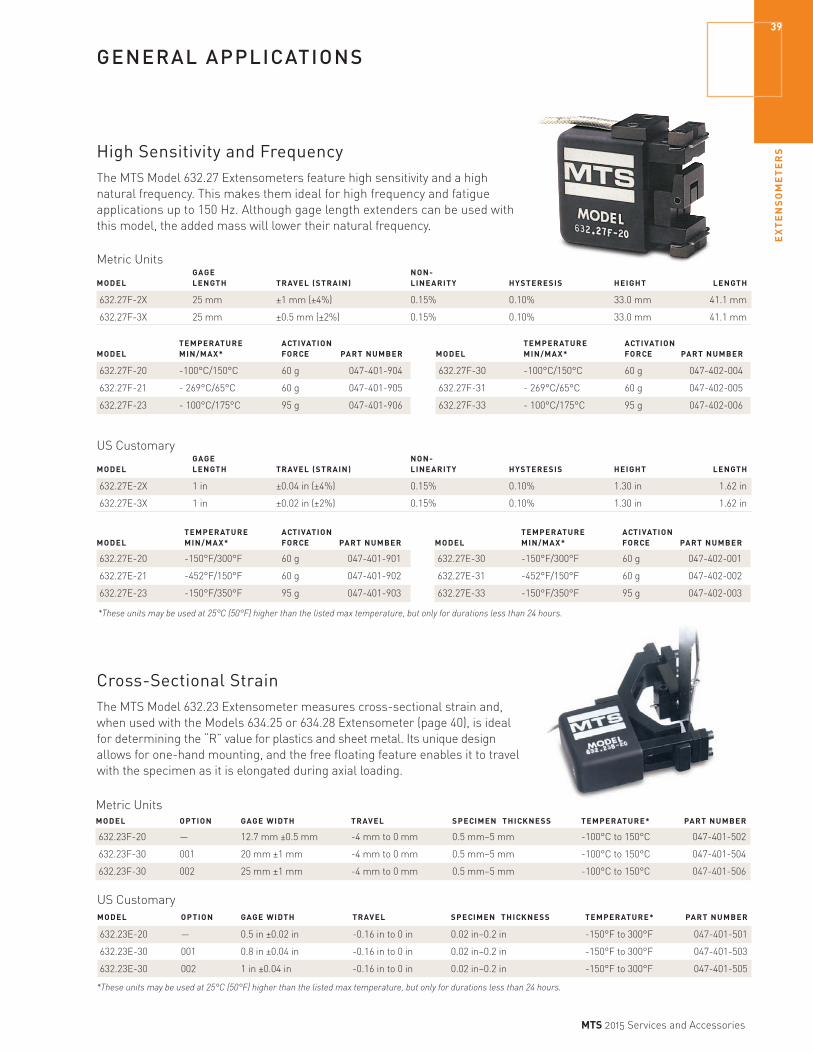
EX
TE
NS
OM
ET
ER
S
39
MTS 2015 Services and Accessories
GENERAL APPLICATIONS
High Sensitivity and FrequencyThe MTS Model 632.27 Extensometers feature high sensitivity and a high natural frequency. This makes them ideal for high frequency and fatigue applications up to 150 Hz. Although gage length extenders can be used with this model, the added mass will lower their natural frequency.
Cross-Sectional StrainThe MTS Model 632.23 Extensometer measures cross-sectional strain and, when used with the Models 634.25 or 634.28 Extensometer (page 40), is ideal for determining the “R” value for plastics and sheet metal. Its unique design allows for one-hand mounting, and the free floating feature enables it to travel with the specimen as it is elongated during axial loading.
Metric Units GAGE NON- MODEL LENGTH TRAVEL (STRAIN) LINEARITY HYSTERESIS HEIGHT LENGTH
632.27F-2X 25 mm ±1 mm (±4%) 0.15% 0.10% 33.0 mm 41.1 mm
632.27F-3X 25 mm ±0.5 mm (±2%) 0.15% 0.10% 33.0 mm 41.1 mm
TEMPERATURE ACTIVATION MODEL MIN/MAX* FORCE PART NUMBER
632.27F-20 -100°C/150°C 60 g 047-401-904
632.27F-21 - 269°C/65°C 60 g 047-401-905
632.27F-23 - 100°C/175°C 95 g 047-401-906
TEMPERATURE ACTIVATION MODEL MIN/MAX* FORCE PART NUMBER
632.27F-30 -100°C/150°C 60 g 047-402-004
632.27F-31 - 269°C/65°C 60 g 047-402-005
632.27F-33 - 100°C/175°C 95 g 047-402-006
US Customary GAGE NON- MODEL LENGTH TRAVEL (STRAIN) LINEARITY HYSTERESIS HEIGHT LENGTH
632.27E-2X 1 in ±0.04 in (±4%) 0.15% 0.10% 1.30 in 1.62 in
632.27E-3X 1 in ±0.02 in (±2%) 0.15% 0.10% 1.30 in 1.62 in
TEMPERATURE ACTIVATION MODEL MIN/MAX* FORCE PART NUMBER
632.27E-20 -150°F/300°F 60 g 047-401-901
632.27E-21 -452°F/150°F 60 g 047-401-902
632.27E-23 -150°F/350°F 95 g 047-401-903
TEMPERATURE ACTIVATION MODEL MIN/MAX* FORCE PART NUMBER
632.27E-30 -150°F/300°F 60 g 047-402-001
632.27E-31 -452°F/150°F 60 g 047-402-002
632.27E-33 -150°F/350°F 95 g 047-402-003
Metric Units
MODEL OPTION GAGE WIDTH TRAVEL SPECIMEN THICKNESS TEMPERATURE* PART NUMBER
632.23F-20 — 12.7 mm ±0.5 mm -4 mm to 0 mm 0.5 mm–5 mm -100°C to 150°C 047-401-502
632.23F-30 001 20 mm ±1 mm -4 mm to 0 mm 0.5 mm–5 mm -100°C to 150°C 047-401-504
632.23F-30 002 25 mm ±1 mm -4 mm to 0 mm 0.5 mm–5 mm -100°C to 150°C 047-401-506
US Customary
MODEL OPTION GAGE WIDTH TRAVEL SPECIMEN THICKNESS TEMPERATURE* PART NUMBER
632.23E-20 — 0.5 in ±0.02 in -0.16 in to 0 in 0.02 in–0.2 in -150°F to 300°F 047-401-501
632.23E-30 001 0.8 in ±0.04 in -0.16 in to 0 in 0.02 in–0.2 in -150°F to 300°F 047-401-503
632.23E-30 002 1 in ±0.04 in -0.16 in to 0 in 0.02 in–0.2 in -150°F to 300°F 047-401-505
*These units may be used at 25°C (50°F) higher than the listed max temperature, but only for durations less than 24 hours.
*These units may be used at 25°C (50°F) higher than the listed max temperature, but only for durations less than 24 hours.

EX
TE
NS
OM
ET
ER
S40
MTS 2015 Services and Accessories
GENERAL APPLICATIONS
Model 634.25 Axial Extensometers with 50 mm (2 in) Gage LengthMTS 634.25 Axial Extensometers are ideal for measuring strain in tension or fatigue testing applications. The standard model includes knife edges and quick attachment fixtures for both flat and round specimens.
Exceptional Accuracy
Meets or exceeds requirements for calibration according to ASTM E83 Class B1 and ISO 9513 Class 0.5 standards. (634.25 models this page)
Metric Units GAGE NON- MODEL LENGTH TRAVEL (STRAIN) LINEARITY HYSTERESIS HEIGHT LENGTH
634.25F-2X 50 mm ±0.05 +25 mm/-5 mm (+50%/-10%) 0.25% 0.10% 58.4 mm 151.4 mm
634.25F-5X 50 mm ±0.05 +25 mm/0 mm (+50%/0%) 0.25% 0.10% 58.4 mm 151.4 mm
TEMPERATURE ACTIVATION MODEL MIN/MAX FORCE PART NUMBER
634.25F-21 -269°C/65°C* 30 g 051-191-607
634.25F-24 -85°C/120°C* 30 g 051-191-608
634.25F-25 -100°C/175°C 45 g 051-191-609
TEMPERATURE ACTIVATION MODEL MIN/MAX FORCE PART NUMBER
634.25F-51 -269°C/65°C* 30 g 051-191-610
634.25F-54 -85°C/120°C* 30 g 051-191-611
634.25F-55 -100°C/175°C 45 g 051-191-612
US Customary GAGE NON- MODEL LENGTH TRAVEL (STRAIN) LINEARITY HYSTERESIS HEIGHT LENGTH
634.25E-2X 2.000 in ±0.002 +1.000 in/-0.200 in (+50%/-10%) 0.25% 0.10% 2.3 in 5.96 in
634.25E-5X 2.000 in ±0.002 +1.000 in/0.000 in (+50%/0%) 0.25% 0.10% 2.3 in 5.96 in
TEMPERATURE ACTIVATION MODEL MIN/MAX FORCE PART NUMBER
634.25E-21 -452°F/150°F* 30 g 051-191-601
634.25E-24 -120°F/250°F* 30 g 051-191-602
634.25E-25 -150°F/350°F 45 g 051-191-603
TEMPERATURE ACTIVATION MODEL MIN/MAX FORCE PART NUMBER
634.25E-51 -452°F/150°F* 30 g 051-191-604
634.25E-54 -120°F/250°F* 30 g 051-191-605
634.25E-55 -150°F/350°F 45 g 051-191-606
Enhanced Travel ExtensometersThese extensometers are well suited for tension testing with +100% strain capability. The Model 632.24 Extensometer utilizes a zero-stop for setting the initial gage length, simplifying mounting. Simply hold the arms together and attach the extensometer to the specimen. The Model 634.28 Extensometer utilizes a unique MTS patented dual cross-flexure system that enables large travel with exceptional accuracy. Both versions are supplied with our patented quick-attach fixtures.
Metric Units TEMPERATURE ACTIVATION PART MODEL MIN/MAX* GAGE LENGTH TRAVEL (STRAIN) NON-LINEARITY HYSTERESIS FORCE NUMBER
632.24F-50 -100°C/150°C 25 mm +25 mm (+100%) 0.25% 0.10% 30 g 047-401-602
634.28F-24 -85°C/120°C 50 mm ±0.05 +50 mm (+100%) 0.25% 0.10% 55 g 056-355-802
US Customary TEMPERATURE ACTIVATION PART MODEL MIN/MAX* GAGE LENGTH TRAVEL (STRAIN) NON-LINEARITY HYSTERESIS FORCE NUMBER
632.24E-50 -150°F/300°F 1 in +1 in (+100%) 0.25% 0.10% 30 g 047-401-601
634.28E-24 -120°F/250°F 2 in ±0.002 +2 in (+100%) 0.25% 0.10% 55 g 056-355-801
*These units may be used at 25°C (50°F) higher than the listed max temperature, but only for durations less than 24 hours.
*These units may be used at 25°C (50°F) higher than the listed max temperature, but only for durations less than 24 hours.

EX
TE
NS
OM
ET
ER
S
41
MTS 2015 Services and Accessories
GENERAL APPLICATIONS
Model 634.31 Extensometer with Multiple Gage LengthsMTS extensometers are precise, durable, and repeatable strain measurement devices. The Model 634.31 Axial Extensometer features multiple gage lengths (nine on the Metric model, six on the US Customary model) to provide the flexibility to run many different tests. The quick-attach fixtures are standard with the Model 634.31. This patented design allows different gage lengths to be used without recalibration. Non-linearity and hysteresis values are typical.
Metric UnitsGAGE NON- ACTIVATION HEIGHT LENGTH TRAVEL (STRAIN) LINEARITY HYSTERESIS FORCE WEIGHT MIN/MAX LENGTH
10.0 mm +4.00 mm/-2.00 mm (+40%/-20%) 0.06% 0.06% 32 g 36 g 32.5 mm/59.4 mm 73.77 mm
15.0 mm +4.00 mm/-2.00 mm (+26.66%/-13.33%) 0.06% 0.06% 32 g 36 g 32.5 mm/59.4 mm 73.77 mm
20.0 mm +4.00 mm/-2.00 mm (+20%/-10%) 0.06% 0.06% 32 g 36 g 32.5 mm/59.4 mm 73.77 mm
25.0 mm +4.00 mm/-2.00 mm (+16%/-8%) 0.06% 0.06% 32 g 41 g 32.5 mm/59.4 mm 73.77 mm
30.0 mm +4.00 mm/-2.00 mm (+13.33%/-6.66%) 0.06% 0.06% 32 g 41 g 32.5 mm/59.4 mm 73.77 mm
35.0 mm +4.00 mm/-2.00 mm (+11.43%/-5.71%) 0.06% 0.06% 32 g 41 g 32.5 mm/59.4 mm 73.77 mm
40.0 mm +4.00 mm/-2.00 mm (+10%/-5%) 0.06% 0.06% 32 g 42 g 32.5 mm/59.4 mm 73.77 mm
45.0 mm +4.00 mm/-2.00 mm (+8.89%/-4.44%) 0.06% 0.06% 32 g 42 g 32.5 mm/59.4 mm 73.77 mm
50.0 mm +4.00 mm/-2.00 mm (+8%/-4%) 0.06% 0.06% 32 g 42 g 32.5 mm/59.4 mm 73.77 mm
MODEL TEMPERATURE MIN/MAX* PART NUMBER
634.31F-21 -269°C/65°C* 052-251-904634.31F-24 -85°C/120°C* 052-251-905634.31F-25 -100°C/175°C 052-251-906
MODEL TEMPERATURE MIN/MAX PART NUMBER
634.31E-21 -452°F/150°F* 052-251-901634.31E-24 -120°F/250°F* 052-251-902
634.31E-25 -150°F/350°F 052-251-903
*These units may be used at 25°C (50°F) higher than the listed max temperature, but only for durations less than 24 hours.
US CustomaryGAGE NON- ACTIVATION HEIGHT LENGTH TRAVEL (STRAIN) LINEARITY HYSTERESIS FORCE WEIGHT MIN/MAX LENGTH
0.500 in +0.200 in/-0.100 in (+40%/-20%) 0.15% 0.08% 40 g 36 g 1.28 in/2.34 in 2.9 in
0.750 in +0.200 in/-0.100 in (+26.66%/-13.33%) 0.15% 0.08% 40 g 36 g 1.28 in/2.34 in 2.9 in
1.000 in +0.200 in/-0.100 in (+20%/-10%) 0.15% 0.08% 40 g 36 g 1.28 in/2.34 in 2.9 in
1.500 in +0.200 in/-0.100 in (+13.33%/-6.66%) 0.15% 0.08% 40 g 42 g 1.28 in/2.34 in 2.9 in
1.750 in +0.200 in/-0.100 in (+11.43%/-5.71%) 0.15% 0.08% 40 g 42 g 1.28 in/2.34 in 2.9 in
2.000 in +0.200 in/-0.100 in (+10%/-5%) 0.15% 0.08% 40 g 42 g 1.28 in/2.34 in 2.9 in
*These units may be used at 25°C (50°F) higher than the listed max temperature, but only for durations less than 24 hours.
Exceptional Accuracy
Meets or exceeds requirements for calibration according to ASTM E83 Class B1 and ISO 9513 Class 0.5 standards.

EX
TE
NS
OM
ET
ER
S42
MTS 2015 Services and Accessories
MINIATURE EXTENSOMETERS
The MTS Model 632.29 family of sub-miniature Extensometers is ideally suited for times when your application requires a small device. Small wires, expensive materials, and small organic specimens are just a few examples where this model will do the job. Though small, these models also feature MTS’ cross-flexure design. They come with a gage fixture for proper gage length setting and a 1000 Ohm fully-active Wheatstone bridge for high sensitivity. The Model 632.29-30 option 012 comes with quick attach for round and flat specimens. Other units include the standard elastic attach kit.
Metric UnitsMODEL OPTION GAGE LENGTH TRAVEL (STRAIN) TEMPERATURE* PART NUMBER
632.29F-20 — 3 mm ±0.24 mm (±8%) -100°C to 150°C 047-402-102
632.29F-30 012 5 mm -0.5 mm/+1.5 mm (-10%/+30%) -100°C to 150°C 047-402-108
632.29F-30 001 6 mm ±0.24 mm (±4%) -100°C to 150°C 047-402-104
US CustomaryMODEL OPTION GAGE LENGTH TRAVEL (STRAIN) TEMPERATURE* PART NUMBER
632.29E-20 — 0.12 in ±0.0096 in (±8%) -150°F to 300°F 047-402-101
632.29E-30 012 0.20 in -0.02 in/+0.06 in (-10%/+30%) -150°F to 300°F 047-402-107
632.29E-30 001 0.24 in ±0.0096 in (±4%) -150°F to 300°F 047-402-103
IMMERSIBLE EXTENSOMETERS
The MTS Model 632.79 Extensometers provide accurate strain measurement while totally immersed in water or saline solution. The patented parallel flexure system accurately translates specimen displacement to the hermetically sealed LVDT (AC conditioning is required). It is designed for both tension and fatigue testing. Other strain ranges are available.
MODEL GAGE LENGTH TRAVEL (STRAIN) TEMPERATURE PART NUMBER
632.79F-01 25 mm (Metric) ±5 mm (±20%) -15°C to 85°C 050-855-602
632.79E-01 1 in (US Customary) ±0.2 in (±20%) 4°F to 185°F 050-855-601
*These units may be used at 25°C (50°F) higher than the listed max temperature, but only for durations less than 24 hours.
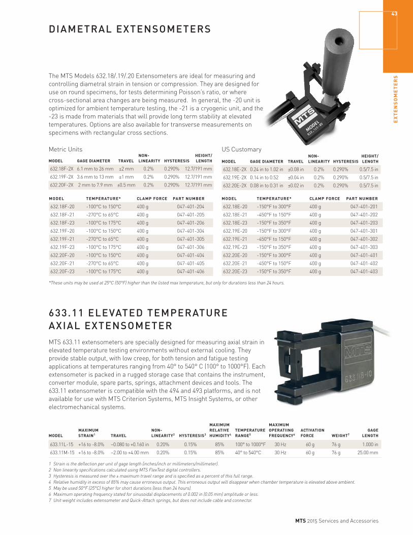
EX
TE
NS
OM
ET
ER
S
43
MTS 2015 Services and Accessories
DIAMETRAL EXTENSOMETERS
The MTS Models 632.18/.19/.20 Extensometers are ideal for measuring and controlling diametral strain in tension or compression. They are designed for use on round specimens, for tests determining Poisson’s ratio, or where cross-sectional area changes are being measured. In general, the -20 unit is optimized for ambient temperature testing, the -21 is a cryogenic unit, and the -23 is made from materials that will provide long term stability at elevated temperatures. Options are also available for transverse measurements on specimens with rectangular cross sections.
Metric Units NON- HEIGHT/ MODEL GAGE DIAMETER TRAVEL LINEARITY HYSTERESIS LENGTH
632.18F-2X 6.1 mm to 26 mm ±2 mm 0.2% 0.290% 12.7/191 mm
632.19F-2X 3.6 mm to 13 mm ±1 mm 0.2% 0.290% 12.7/191 mm
632.20F-2X 2 mm to 7.9 mm ±0.5 mm 0.2% 0.290% 12.7/191 mm
MODEL TEMPERATURE* CLAMP FORCE PART NUMBER
632.18F-20 -100°C to 150°C 400 g 047-401-204
632.18F-21 -270°C to 65°C 400 g 047-401-205
632.18F-23 -100°C to 175°C 400 g 047-401-206
632.19F-20 -100°C to 150°C 400 g 047-401-304
632.19F-21 -270°C to 65°C 400 g 047-401-305
632.19F-23 -100°C to 175°C 400 g 047-401-306
632.20F-20 -100°C to 150°C 400 g 047-401-404
632.20F-21 -270°C to 65°C 400 g 047-401-405
632.20F-23 -100°C to 175°C 400 g 047-401-406
US Customary NON- HEIGHT/ MODEL GAGE DIAMETER TRAVEL LINEARITY HYSTERESIS LENGTH
632.18E-2X 0.24 in to 1.02 in ±0.08 in 0.2% 0.290% 0.5/7.5 in
632.19E-2X 0.14 in to 0.52 ±0.04 in 0.2% 0.290% 0.5/7.5 in
632.20E-2X 0.08 in to 0.31 in ±0.02 in 0.2% 0.290% 0.5/7.5 in
MODEL TEMPERATURE* CLAMP FORCE PART NUMBER
632.18E-20 -150°F to 300°F 400 g 047-401-201
632.18E-21 -450°F to 150°F 400 g 047-401-202
632.18E-23 -150°F to 350°F 400 g 047-401-203
632.19E-20 -150°F to 300°F 400 g 047-401-301
632.19E-21 -450°F to 150°F 400 g 047-401-302
632.19E-23 -150°F to 350°F 400 g 047-401-303
632.20E-20 -150°F to 300°F 400 g 047-401-401
632.20E-21 -450°F to 150°F 400 g 047-401-402
632.20E-23 -150°F to 350°F 400 g 047-401-403
*These units may be used at 25°C (50°F) higher than the listed max temperature, but only for durations less than 24 hours.
MTS 633.11 extensometers are specially designed for measuring axial strain in elevated temperature testing environments without external cooling. They provide stable output, with low creep, for both tension and fatigue testing applications at temperatures ranging from 40° to 540° C (100° to 1000°F). Each extensometer is packed in a rugged storage case that contains the instrument, converter module, spare parts, springs, attachment devices and tools. The 633.11 extensometer is compatible with the 494 and 493 platforms, and is not available for use with MTS Criterion Systems, MTS Insight Systems, or other electromechanical systems.
633.11 ELEVATED TEMPERATURE AXIAL EXTENSOMETER
MAXIMUM MAXIMUM MAXIMUM NON- RELATIVE TEMPERATURE OPERATIING ACTIVATION GAGEMODEL STRAIN1 TRAVEL LINEARITY2 HYSTERESIS3 HUMIDITY4 RANGE5 FREQUENCY6 FORCE WEIGHT7 LENGTH
633.11L-15 +16 to -8.0% –0.080 to +0.160 in 0.20% 0.15% 85% 100° to 1000°F 30 Hz 60 g 76 g 1.000 in
633.11M-15 +16 to -8.0% –2.00 to +4.00 mm 0.20% 0.15% 85% 40° to 540°C 30 Hz 60 g 76 g 25.00 mm
1 Strain is the deflection per unit of gage length (inches/inch or millimeters/millimeter).2 Non linearity specifications calculated using MTS FlexTest digital controllers. 3 Hysteresis is measured over the ± maximum travel range and is specified as a percent of this full range.4 Relative humidity in excess of 85% may cause erroneous output. This erroneous output will disappear when chamber temperature is elevated above ambient. 5 May be used 50°F (25°C) higher for short durations (less than 24 hours).6 Maximum operating frequency stated for sinusoidal displacements of 0.002 in (0.05 mm) amplitude or less.7 Unit weight includes extensometer and Quick-Attach springs, but does not include cable and connector.

EX
TE
NS
OM
ET
ER
S44
MTS 2015 Services and Accessories
HIGH-TEMPERATURE EXTENSOMETERS
The MTS Model 632.50 High Temperature Axial Extensometer is designed for measuring axial strain in high temperature tension, compression and through-zero fatigue testing applications. Included ceramic extension rods extend into the hot zone and minimize rod creep, thermal expansion errors and conduction losses from the specimen. Air cooling required.
Exceptional Accuracy
Meets or exceeds requirements for calibrations according to ASTM E83 Class B1 and ISO 9513 Class 0.5 standards
Metric Units
GAGE STRAIN MAXIMUM CONTACT
MODEL LENGTH RANGE TEMPERATURE FORCE PART NUMBER*
632.50F-01 25 mm +15%/-15% 1200°C 400 g 047-402-548
632.50F-04 12 mm +20%/-10% 1200°C 780 g 047-402-539
US Customary
GAGE STRAIN MAXIMUM CONTACT MODEL LENGTH RANGE TEMPERATURE FORCE PART NUMBER*
632.50E-01 1.00 in +15%/-15% 2200°F 400 g 047-402-547
632.50E-04 0.50 in +20%/-10% 2200°F 780 g 047-402-525
*Mount is not required when using with 653.xxB furnace, for other installations contact MTS.
MTS Model 632.51 High Temperature Axial Extensometer is designed for measuring axial strain in high temperature tension, compression and through-zero fatigue testing applications. Included ceramic extension rods extend into the hot zone and minimize rod creep, thermal expansion errors and conduction losses from the specimen. Water cooling required.
Metric Units
GAGE STRAIN MAXIMUM CONTACT
MODEL LENGTH RANGE TEMPERATURE FORCE PART NUMBER*
632.51F-01 25 mm +15%/-15% 1200°C 400 g 047-402-652
632.51F-04 12 mm +20%/-10% 1200°C 780 g 047-402-651
US Customary
GAGE STRAIN MAXIMUM CONTACT MODEL LENGTH RANGE TEMPERATURE FORCE PART NUMBER*
632.51E-01 1.00 in +15%/-15% 2200°F 400 g 047-402-653
632.51E-04 0.50 in +20%/-10% 2200°F 780 g 047-402-650
*Mount is not required when using with 653.xxB furnace, for other installations contact MTS.

EX
TE
NS
OM
ET
ER
S
45
MTS 2015 Services and Accessories
HIGH-TEMPERATURE EXTENSOMETERS
The Model 632.53 Extensometer features non-linearity less than 0.15% and hysteresis less than 0.10% for all units. These units come with two pairs of ceramic contact rods, extending 66 mm (2.6 in) from the heat shield, 3.5 mm (0.138 in) in diameter, with V-chisel ends for round specimens. Other rod end geometries are also available.Air cooling required.
Exceptional Accuracy
Meets or exceeds requirements for calibrations according to ASTM E83 Class B1 and ISO 9513 Class 0.5 standards
Metric Units
GAGE STRAIN MAXIMUM CONTACT
MODEL LENGTH RANGE TEMPERATURE FORCE PART NUMBER1 PART NUMBER2
632.53F-11 25 mm +10%/-5% 1200°C 300 g 047-404-111 057-029-011
632.53F-14 12 mm +20%/-10% 1200°C 300 g 047-404-105 057-029-013
632.53F-11 25 mm +10%/-5% 1200°C 400 g 047-404-112 057-029-012
632.53F-14 12 mm +20%/-10% 1200°C 400 g 047-404-106 057-029-006
US Customary
GAGE STRAIN MAXIMUM CONTACT
MODEL LENGTH RANGE TEMPERATURE FORCE PART NUMBER1 PART NUMBER2
632.53E-11 1.00 in +10%/-5% 2200°F 300 g 047-404-108 057-029-008
632.53E-14 0.50 in +20%/-10% 2200°F 300 g 047-404-102 057-029-002
632.53E-11 1.00 in +10%/-5% 2200°F 400 g 047-404-109 057-029-009
632.53E-14 0.50 in +20%/-10% 2200°F 400 g 047-404-103 057-029-003
1. Compatible with column mounting or 653.xxB furnace.2. Extensometer including interface for 653.xxA dual column mounting bracket.
The MTS Model 632.54 Extensometer is an inexpensive solution for high-temperature testing with induction heaters or furnaces. With a contact force of only 100 grams per rod, these units come with two pairs of ceramic contact rods, extending 66 mm (2.6 in) from the heat shield, 2 mm (0.079 in) in diameter, with V-chisel ends for round specimens. Other rod end geometries are also available.
Air cooling required.
US Customary
GAGE STRAIN MAXIMUM CONTACT
MODEL LENGTH RANGE TEMPERATURE FORCE PART NUMBER1 PART NUMBER2
632.54E-11 1.00 in +10%/-5% 2200°F 100 g 047-404-301 057-028-301
632.54E-14 0.50 in +20%/-10% 2200°F 100 g 047-404-302 057-028-302
1. Compatible with column mounting or 653.xxB furnace.2. Extensometer including interface for 653.xxA dual column mounting bracket.
Metric Units
GAGE STRAIN MAXIMUM CONTACT
MODEL LENGTH RANGE TEMPERATURE FORCE PART NUMBER1 PART NUMBER2
632.54F-11 25 mm +10%/-5% 1200°C 100 g 047-404-303 057-028-303
632.54F-14 12 mm +20%/-10% 1200°C 100 g 047-404-304 057-028-304
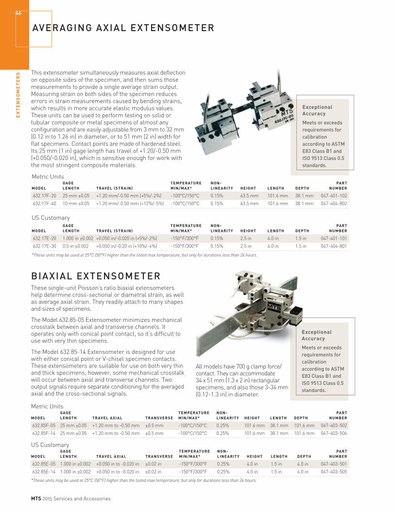
EX
TE
NS
OM
ET
ER
S46
MTS 2015 Services and Accessories
Exceptional Accuracy
Meets or exceeds requirements for calibration according to ASTM E83 Class B1 and ISO 9513 Class 0.5 standards.
AVERAGING AXIAL EXTENSOMETER
This extensometer simultaneously measures axial deflection on opposite sides of the specimen, and then sums those measurements to provide a single average strain output. Measuring strain on both sides of the specimen reduces errors in strain measurements caused by bending strains, which results in more accurate elastic modulus values. These units can be used to perform testing on solid or tubular composite or metal specimens of almost any configuration and are easily adjustable from 3 mm to 32 mm (0.12 in to 1.26 in) in diameter, or to 51 mm (2 in) width for flat specimens. Contact points are made of hardened steel. Its 25 mm (1 in) gage length has travel of +1.20/-0.50 mm (+0.050/-0.020 in), which is sensitive enough for work with the most stringent composite materials.
Exceptional Accuracy
Meets or exceeds requirements for calibration according to ASTM E83 Class B1 and ISO 9513 Class 0.5 standards.
BIAXIAL EXTENSOMETERThese single-unit Poisson’s ratio biaxial extensometers help determine cross-sectional or diametral strain, as well as average axial strain. They readily attach to many shapes and sizes of specimens.
The Model 632.85-05 Extensometer minimizes mechanical crosstalk between axial and transverse channels. It operates only with conical point contact, so it’s difficult to use with very thin specimens.
The Model 632.85-14 Extensometer is designed for use with either conical point or V-chisel specimen contacts. These extensometers are suitable for use on both very thin and thick specimens; however, some mechanical crosstalk will occur between axial and transverse channels. Two output signals require separate conditioning for the averaged axial and the cross-sectional signals.
Metric Units GAGE TEMPERATURE NON- PART MODEL LENGTH TRAVEL (STRAIN) MIN/MAX* LINEARITY HEIGHT LENGTH DEPTH NUMBER
632.17F-20 25 mm ±0.05 +1.20 mm/-0.50 mm (+5%/-2%) -100°C/150°C 0.15% 63.5 mm 101.6 mm 38.1 mm 047-401-102
632.17F-40 10 mm ±0.05 +1.20 mm/-0.50 mm (+12%/-5%) -100°C/150°C 0.15% 63.5 mm 101.6 mm 38.1 mm 047-404-802
US Customary GAGE TEMPERATURE NON- PART MODEL LENGTH TRAVEL (STRAIN) MIN/MAX* LINEARITY HEIGHT LENGTH DEPTH NUMBER
632.17E-20 1.000 in ±0.002 +0.050 in/-0.020 in (+5%/-2%) -150°F/300°F 0.15% 2.5 in 4.0 in 1.5 in 047-401-101
632.17E-30 0.5 in ±0.002 +0.050 in/-0.20 in (+10%/-4%) -150°F/300°F 0.15% 2.5 in 4.0 in 1.5 in 047-404-801
*These units may be used at 25°C (50°F) higher than the listed max temperature, but only for durations less than 24 hours.
Metric Units GAGE TEMPERATURE NON- PART MODEL LENGTH TRAVEL AXIAL TRANSVERSE MIN/MAX* LINEARITY HEIGHT LENGTH DEPTH NUMBER
632.85F-05 25 mm ±0.05 +1.20 mm to -0.50 mm ±0.5 mm -100°C/150°C 0.25% 101.6 mm 38.1 mm 101.6 mm 047-403-502
632.85F-14 25 mm ±0.05 +1.20 mm to -0.50 mm ±0.5 mm -100°C/150°C 0.25% 101.6 mm 38.1 mm 101.6 mm 047-403-506
US Customary GAGE TEMPERATURE NON- PART MODEL LENGTH TRAVEL AXIAL TRANSVERSE MIN/MAX* LINEARITY HEIGHT LENGTH DEPTH NUMBER
632.85E-05 1.000 in ±0.002 +0.050 in to -0.020 in ±0.02 in -150°F/300°F 0.25% 4.0 in 1.5 in 4.0 in 047-403-501
632.85E-14 1.000 in ±0.002 +0.050 in to -0.020 in ±0.02 in -150°F/300°F 0.25% 4.0 in 1.5 in 4.0 in 047-403-505
*These units may be used at 25°C (50°F) higher than the listed max temperature, but only for durations less than 24 hours.
All models have 700 g clamp force/contact. They can accommodate 34 x 51 mm (1.3 x 2 in) rectangular specimens, and also those 3-34 mm (0.12-1.3 in) in diameter.
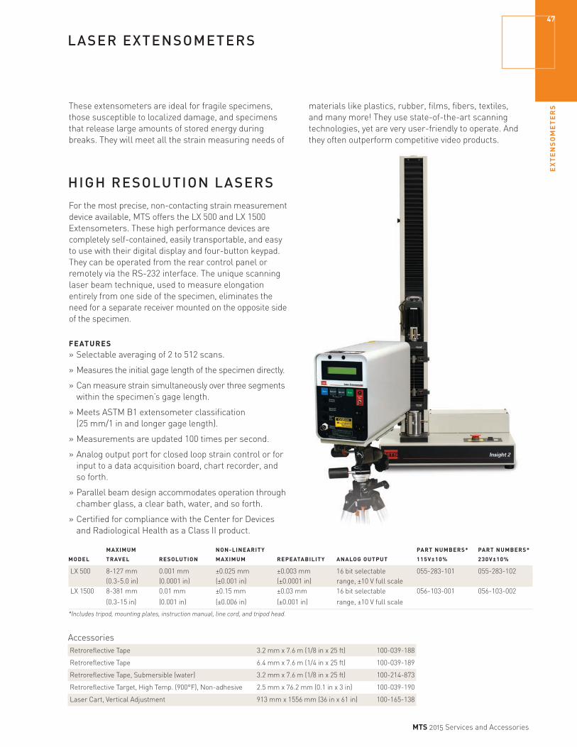
EX
TE
NS
OM
ET
ER
S
47
MTS 2015 Services and Accessories
LASER EXTENSOMETERS
These extensometers are ideal for fragile specimens, those susceptible to localized damage, and specimens that release large amounts of stored energy during breaks. They will meet all the strain measuring needs of
materials like plastics, rubber, films, fibers, textiles, and many more! They use state-of-the-art scanning technologies, yet are very user-friendly to operate. And they often outperform competitive video products.
MAXIMUM NON-LINEARITY PART NUMBERS* PART NUMBERS*
MODEL TRAVEL RESOLUTION MAXIMUM REPEATABILITY ANALOG OUTPUT 115V±10% 230V±10%
LX 500 8-127 mm 0.001 mm ±0.025 mm ±0.003 mm 16 bit selectable 055-283-101 055-283-102 (0.3-5.0 in) (0.0001 in) (±0.001 in) (±0.0001 in) range, ±10 V full scaleLX 1500 8-381 mm 0.01 mm ±0.15 mm ±0.03 mm 16 bit selectable 056-103-001 056-103-002
(0.3-15 in) (0.001 in) (±0.006 in) (±0.001 in) range, ±10 V full scale
*Includes tripod, mounting plates, instruction manual, line cord, and tripod head.
HIGH RESOLUTION LASERSFor the most precise, non-contacting strain measurement device available, MTS offers the LX 500 and LX 1500 Extensometers. These high performance devices are completely self-contained, easily transportable, and easy to use with their digital display and four-button keypad. They can be operated from the rear control panel or remotely via the RS-232 interface. The unique scanning laser beam technique, used to measure elongation entirely from one side of the specimen, eliminates the need for a separate receiver mounted on the opposite side of the specimen.
FEATURES» Selectable averaging of 2 to 512 scans.
» Measures the initial gage length of the specimen directly.
» Can measure strain simultaneously over three segments within the specimen’s gage length.
» Meets ASTM B1 extensometer classification (25 mm/1 in and longer gage length).
» Measurements are updated 100 times per second.
» Analog output port for closed loop strain control or for input to a data acquisition board, chart recorder, and so forth.
» Parallel beam design accommodates operation through chamber glass, a clear bath, water, and so forth.
» Certified for compliance with the Center for Devices and Radiological Health as a Class II product.
AccessoriesRetroreflective Tape 3.2 mm x 7.6 m (1/8 in x 25 ft) 100-039-188
Retroreflective Tape 6.4 mm x 7.6 m (1/4 in x 25 ft) 100-039-189
Retroreflective Tape, Submersible (water) 3.2 mm x 7.6 m (1/8 in x 25 ft) 100-214-873
Retroreflective Target, High Temp. (900°F), Non-adhesive 2.5 mm x 76.2 mm (0.1 in x 3 in) 100-039-190
Laser Cart, Vertical Adjustment 913 mm x 1556 mm (36 in x 61 in) 100-165-138

EX
TE
NS
OM
ET
ER
S48
MTS 2015 Services and Accessories
CLIP-ON DISPLACEMENT GAGES
MTS clip-on displacement gages are double cantilever displacement-type gages primarily used in fracture mechanics testing, KIC, JIC, and crack growth. They can also be used in a variety of other applications including: measuring displacements of components and specimens with odd geometrics; elongation studies; and tests of pipe, bars, and rods.
Without any special precautions, this unit can be immersed in a wide variety of non-conductive fluids.
Model 632.02 Clip-On GageThe Model 632.02 Clip-On Gages are designed specifically to meet ASTM E399 requirements and are suitable to perform tests to determine KIC, JIC, crack growth rates. They can be used with a variety of specimens including compact tension, WOL, round compact tension, C-shaped, bend, and other common specimens or panels.
Model 632.05 Clip-On GageThese gages are designed for use at very high frequencies. Because of their sensitivity, visual monitoring of the specimen during testing is not required. Crack growth will be apparent on readout.
Standard equipment includes the gage and storage case, two reusable hardened knife edges for attachment to the specimen, and an instruction manual.
Metric Units GAGE NON- MAX COMPRESSED MODEL LENGTH TRAVEL LINEARITY FREQUENCY FORCE HEIGHT LENGTH
632.02F-2X 5 mm +3 mm/-1 mm 0.15% 50 Hz 2500 g 30.5 mm 48.3 mm
632.05F-6X 26.4 mm ±0.5 mm 0.25% 300 Hz 1600 g 34 mm 29 mm
US Customary GAGE NON- MAX COMPRESSED MODEL LENGTH TRAVEL LINEARITY FREQUENCY FORCE HEIGHT LENGTH
632.02E-2X 0.200 in +.100 in/-0.05 in 0.15% 50 Hz 2500 g 1.2 in 1.9 in
632.05E-6X 1.04 in ±0.02 in 0.25% 300 Hz 1600 g 1.4 in 1.1 in
MODEL TEMPERATURE MIN/MAX* PART NUMBER
632.02F-20 -100°C/150°C 047-400-104
632.02F-21 -269°C/65°C 047-400-105
632.02F-23 -100°C/175°C 047-400-106
MODEL TEMPERATURE MIN/MAX* PART NUMBER
632.05F-60 -100°C/150°C 047-400-404
632.05F-61 -269°C/65°C 047-400-405
632.05F-63 -100°C/175°C 047-400-406
MODEL TEMPERATURE MIN/MAX* PART NUMBER
632.02E-20 -150°F/300°F 047-400-101
632.02E-21 -452°F/150°F 047-400-102
632.02E-23 -150°F/350°F 047-400-103
MODEL TEMPERATURE MIN/MAX* PART NUMBER
632.05E-60 -150°F/300°F 047-400-401
632.05E-61 -452°F/150°F 047-400-402
632.05E-63 -150°F/350°F 047-400-403
*These units may be used at 25°C (50°F) higher than the listed max temperature, but only for durations less than 24 hours.
*These units may be used at 25°C (50°F) higher than the listed max temperature, but only for durations less than 24 hours.

EX
TE
NS
OM
ET
ER
S
49
MTS 2015 Services and Accessories
CLIP-ON DISPLACEMENT GAGES
Model 632.03 Clip-On GagesThese clip-on gages are used to perform the ASTM standard fracture mechanics tests for KIC, JIC, crack growth, and R-curve determination. They can be used with compact tension, round compact tension, C-shaped, WOL, bend specimen, and other specimen geometries. They feature an improved slot geometry with three-point contact knife edges for better location and more accurate measurement than the 632.02 family. The 632.03-2x is the most common unit; the -3x series features more options for gage lengths and longer travel for J-integral and crack growth tests.
General Specifications for Model 632.03 UnitsMODEL GAGE LENGTH TRAVEL NON-LINEARITY MAX FREQUENCY COMPRESSED FORCE
632.03-2X 12 mm (0.475 in) 4 mm (0.15 in) 0.15% 100 Hz 2500 g
632.03-3X see below various 0.20% various various
Metric Units-2X MODELS TEMPERATURE* PART NUMBER
632.03F-20 -100°C to 150°C 047-400-204
632.03F-21 -270°C to 65°C 047-400-205
632.03F-23 -100°C to 175°C 047-400-206
-100°C TO 150°C* -270°C TO 65°C* -100°C TO 175°C* -3X MODELS (OPTION) GAGE LENGTH TRAVEL PART NUMBER (FOR -30) PART NUMBER (FOR -31) PART NUMBER (FOR -33)
632.03F-3X (001) 2 mm 4 mm 047-400-310 047-400-328 047-400-346
632.03F-3X (002) 2.5 mm 4 mm 047-400-311 047-400-329 047-400-347
632.03F-3X (003) 4.5 mm 4 mm 047-400-312 047-400-330 047-400-348
632.03F-3X (004) 5 mm 4 mm 047-400-313 047-400-331 047-400-349
632.03F-3X (005) 6 mm 6 mm 047-400-314 047-400-332 047-400-350
632.03F-3X (006) 6 mm 12 mm 047-400-315 047-400-333 047-400-351
632.03F-3X (007) 12 mm 12 mm 047-400-316 047-400-334 047-400-352
632.03F-3X (008) 20 mm 12 mm 047-400-317 047-400-335 047-400-353
632.03F-3X (009) 13 mm 12 mm 047-400-318 047-400-336 047-400-354
*These units may be used at 25°C (50°F) higher than the listed max temperature, but only for durations less than 24 hours.
US Customary-2X MODELS TEMPERATURE* PART NUMBER
632.03E-20 -150°F to 300°F 047-400-201
632.03E-21 -452°F to 150°F 047-400-202
632.03E-23 -150°F to 350°F 047-400-203
-150°F TO 300°F* -452°F TO 150°F* -150°F TO 350°F* -3X MODELS (OPTION) GAGE LENGTH TRAVEL PART NUMBER (FOR -30) PART NUMBER (FOR -31) PART NUMBER (FOR -33)
632.03E-3X (001) 0.075 in 0.15 in 047-400-301 047-400-319 047-400-337
632.03E-3X (002) 0.10 in 0.15 in 047-400-302 047-400-320 047-400-338
632.03E-3X (003) 0.175 in 0.15 in 047-400-303 047-400-321 047-400-339
632.03E-3X (004) 0.20 in 0.15 in 047-400-304 047-400-322 047-400-340
632.03E-3X (005) 0.25 in 0.25 in 047-400-305 047-400-323 047-400-341
632.03E-3X (006) 0.25 in 0.50 in 047-400-306 047-400-324 047-400-342
632.03E-3X (007) 0.475 in 0.50 in 047-400-307 047-400-325 047-400-343
632.03E-3X (008) 0.80 in 0.50 in 047-400-308 047-400-326 047-400-344
632.03E-3X (009) 0.50 in 0.50 in 047-400-309 047-400-327 047-400-345
*These units may be used at 25°C (50°F) higher than the listed max temperature, but only for durations less than 24 hours.

EX
TE
NS
OM
ET
ER
S50
MTS 2015 Services and Accessories
CLIP-ON DISPLACEMENT GAGES
Model 632.06 Displacement GageThis is an extremely versatile displacement gage that can be used to measure fixture, shaft, or any other component movement during the test cycle. Designed for use where small deformations must be measured, in bend tests, or where unusual geometries are involved; it’s protected from overtravel in all directions. The gage arm releases in either a positive or negative overtravel situation or when a side
load is applied. If the arm should release, it can be reset without changing gage body position. This unit comes with an adjustable mounting block. When properly positioned, the unit can be locked in place. Displacement measurements can be made with the gage in contact against the specimen or as an active component in the force train. Non-linearity of the Model 632.06 Displacement Gage is 0.25%.
Specifications FORCE MODEL OPTION TRAVEL ZERO ADV. AT ZERO HEIGHT LENGTH
632.06H-2X — ±4 mm (±0.16 in) 8 mm (0.30 in) 150 g 101 mm (4 in) 101 mm (4 in)
632.06H-3X 001 ±2 mm (±0.08 in) 8 mm (0.30 in) 150 g 101 mm (4 in) 101 mm (4 in)
632.06H-3X 002 ±1 mm (±0.04 in) 8 mm (0.30 in) 250 g 101 mm (4 in) 69 mm (2.7 in)
632.06H-3X 003 ±6 mm (±0.25 in) 8 mm (0.30 in) 150 g 101 mm (4 in) 101 mm (4 in)
632.06H-3X 004 ±8 mm (±0.32 in) 8 mm (0.30 in) 100 g 101 mm (4 in) 140 mm (5.5 in)
632.06H-3X 005 ±12.5 mm (±0.50 in) 8 mm (0.30 in) 80 g 101 mm (4 in) 190 mm (7.5 in)
632.06H-3X 006 ±25 mm (±1.0 in) 8 mm (0.30 in) 35 g 101 mm (4 in) 343 mm (13.5 in)
MODEL OPTION TRAVEL TEMPERATURE* PART NUMBER
632.06H-20 — ±4 mm (±0.16 in) -100°C/150°C (-150°F/300°F) 047-400-501
632.06H-21 — ±4 mm (±0.16 in) -270°C/65°C (-452°F/150°F) 047-400-502
632.06H-23 — ±4 mm (±0.16 in) -100°C/175°C (-150°F/350°F) 047-400-503
632.06H-30 001 ±2 mm (±0.08 in) -100°C/150°C (-150°F/300°F) 047-400-504
632.06H-31 001 ±2 mm (±0.08 in) -270°C/65°C (-452°F/150°F) 047-400-505
632.06H-33 001 ±2 mm (±0.08 in) -100°C/175°C (-150°F/350°F) 047-400-506
632.06H-30 002 ±1 mm (±0.04 in) -100°C/150°C (-150°F/300°F) 047-400-507
632.06H-31 002 ±1 mm (±0.04 in) -270°C/65°C (-452°F/150°F) 047-400-508
632.06H-33 002 ±1 mm (±0.04 in) -100°C/175°C (-150°F/350°F) 047-400-509
632.06H-30 003 ±6 mm (±0.25 in) -100°C/150°C (-150°F/300°F) 047-400-510
632.06H-31 003 ±6 mm (±0.25 in) -270°C/65°C (-452°F/150°F) 047-400-511
632.06H-33 003 ±6 mm (±0.25 in) -100°C/175°C (-150°F/350°F) 047-400-512
632.06H-30 004 ±8 mm (±0.32 in) -100°C/150°C (-150°F/300°F) 047-400-513
632.06H-31 004 ±8 mm (±0.32 in) -270°C/65°C (-452°F/150°F) 047-400-514
632.06H-33 004 ±8 mm (±0.32 in) -100°C/175°C (-150°F/350°F) 047-400-515
632.06H-30 005 ±12.5 mm (±0.50 in) -100°C/150°C (-150°F/300°F) 047-400-516
632.06H-31 005 ±12.5 mm (±0.50 in) -270°C/65°C (-452°F/150°F) 047-400-517
632.06H-33 005 ±12.5 mm (±0.50 in) -100°C/175°C (-150°F/350°F) 047-400-518
632.06H-30 006 ±25 mm (±1.0 in) -100°C/150°C (-150°F/300°F) 047-400-519
632.06H-31 006 ±25 mm (±1.0 in) -270°C/65°C (-452°F/150°F) 047-400-520
*All these units may be used at 25°C (50°F) higher than the listed max temperature, but only for durations less than 24 hours.

EX
TE
NS
OM
ET
ER
S
51
MTS 2015 Services and Accessories
OTHER APPLICATIONS
With over 101 different models, MTS has the largest offering of extensometers in the world. In fact, here’s a list of some of our other models that you won’t find in this catalog. Contact us if you’re interested in any of these capabilities!
HOSTILE ENVIRONMENT DISPLACEMENT GAGE
(MODEL 632.10)Use for salt fog or boiling water reaction simulations. Standard temperature range to 290°C (550°F), with options to 400°C (750°F).
BIOMEDICAL SOFT TISSUE OR SIMILAR MATERIAL
(MODEL 632.32)Ultra-low contact force with serrated knife edges.
HIGH-TEMPERATURE AXIAL APPLICATIONS
(MODELS 632.50/51/59)Many options available. Air-cooled, water-cooled, vacuum, and temperatures to 2300°C (4100°F).
HIGH-TEMPERATURE DIAMETRAL/TRANSVERSE
APPLICATIONS (MODELS 632.60/61)Standard models to 1000°C (2200°F), with options available to 1500°C (2700°F).
HIGH-TEMPERATURE AXIAL TORSIONAL APPLICATIONS
(MODELS 632.68 AND 632.80)Simultaneous measurement of axial and torsional strain. The Model 632.80 has a temperature range of -100°C to 150°C (-150°F to 300°F), while the high-temperature version Model 632.68 is rated up to 1200°C (2200°F).
AXIAL ROCK MECHANICS APPLICATIONS
(MODELS 632.90/94)Models available for use in air, or in high pressure, single measurement, and averaged axial applications.
CIRCUMFERENTIAL APPLICATIONS (MODEL 632.21/92)Unique roller chain design provides low hysteresis.

EX
TE
NS
OM
ET
ER
S52
MTS 2015 Services and Accessories
ACCESSORIES FOR MTS EXTENSOMETERS
Expand Your Range of Use with Gage Length Extenders for MTS ExtensometersCheck your extensometer’s type before choosing your extender. Metrics extensometers (F) require a different extender than US Customary extensometers (E).
For the best value, purchase a “kit” with three or four extenders.
METRIC GAGE LENGTH EXTENSOMETER METRIC MODEL WITH EXTENDER MODELS (TYPE) PART NUMBER
634.15C-30 50 mm 634.11/12 (F) 051-191-901
634.15C-31 100 mm 634.11/12 (F) 051-191-902
634.15C-32 150 mm 634.11/12 (F) 051-191-903
634.15C-33 200 mm 634.11/12 (F) 051-191-904
634.15C-37 Kit of 50, 100, 150, & 200 mm extenders 051-191-905
634.15C-40 100 mm 634.25 (F) 051-191-908
634.15C-41 150 mm 634.25 (F) 051-191-909
634.15C-42 200 mm 634.25 (F) 051-191-910
634.15C-47 Kit of 100, 150, & 200 mm extenders 051-191-911
US CUSTOMARY GAGE LENGTH EXTENSOMETER US CUSTOMARY MODEL WITH EXTENDER MODELS (TYPE) PART NUMBER
634.15B-30 2 in 634.11/12 (E) 051-191-801
634.15B-31 4 in 634.11/12 (E) 051-191-802
634.15B-32 6 in 634.11/12 (E) 051-191-803
634.15B-33 8 in 634.11/12 (E) 051-191-804
634.15B-37 Kit of 2, 4, 6, & 8 in extenders 051-191-805
634.15B-40 4 in 634.25 (E) 051-191-808
634.15B-41 6 in 634.25 (E) 051-191-809
634.15B-42 8 in 634.25 (E) 051-191-810
634.15B-47 Kit of 4,6, & 8 in extenders 051-191-811
Quick Attach Replacement PartsDESCRIPTION PART NUMBER
Quick Attach Spring Set (includes 2 springs)
For all 634.xx models except 634.31F 047-201-911
For Model 634.31F 047-201-920
Spring Retainer (holds 1 Q/A spring in place) 055-467-601

EX
TE
NS
OM
ET
ER
S
53
MTS 2015 Services and Accessories
SPECIMEN ATTACHMENT KITS
Large Diameter Specimens As the diameter of a specimen increases, the normal force holding the extensometer in place is
reduced. Under such circumstances, this kit provides for a more effective attachment angle,
resulting in increased normal force for proper stability. This kit includes two remote spring attachment bracket assemblies that mount on the extensometer arms, and an
assortment of 16 tension springs. The large diameter specimen attachment kit expands your range of testing capabilities. Use with Models 632.11/.12/.25 and 634.11/.12/.25 on specimens larger than 32 mm (1.25 in) in diameter.
REPLACEMENT KNIFE EDGESExtensometers These knife edges are exact replacements for those provided with MTS extensometers. They are stainless steel with a Rockwell hardness of Rc 58 to 60. Knife edges for use in testing round specimens have a 90° included angle. Those for use in testing flat specimens provide three-point specimen contact by means of one single point and one double-point contact knife edge.
Pictured are straight edges used with round specimens (left) and three-point edges for use with flat specimens.
Flat Specimens—Disc Method This flat attachment method is designed primarily for thin specimens which are 12 mm (0.5 in) or less in width. In effect, this kit makes a flat sample appear as a round specimen for extensometer mounting purposes.
Flat Specimens—Wire Form MethodThis attachment method consists of mounting a separate, heavy duty, remote spring bracket assembly to the arms of the extensometer. Once mounted, it may be left in place and will not affect performance on round specimens. The formed wire reacts with the force of the springs directly across from the knife edges.
Pictured are 632.02 (right) and 632.03/05 Clip-On Gage knife edges.
Clip Gages MTS provides two types of reusable clip knife edges which may be attached to specimens. The Model 632.02 type is designed to comply with ASTM E399. The second type is a knife edge designed to fit the improved slot geometry provided with Model 632.03 and 632.05 Clip-On Gages. The three-point contacts are both radiused and crowned.
634.XX 632.XX DESCRIPTION PART NUMBER PART NUMBER
Large Diameter Kit for 63x.11/.12/.25 053-063-001 038-863-801
Flat Specimen Attachment Kit—Disc Method 100-020-108 034-505-201
Flat Specimen Attachment Kit—Wire Form Method, 100-058-679 100-053-079for specimens up to 25 mm (1 in) wide
Flat Specimen Attachment Kit—Wire Form Method, 100-049-139 033-316-701for specimens 25 mm to 50 mm (1 in to 2 in) wide
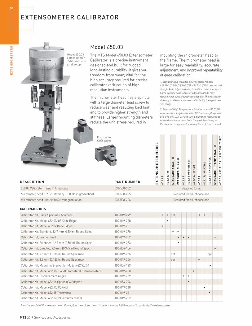
EX
TE
NS
OM
ET
ER
S54
MTS 2015 Services and Accessories
EXTENSOMETER CALIBRATOR
Fixtures for COD gages
Model 650.03 Extensometer Calibrator with axial setup
EX
TE
NS
OM
ET
ER
MO
DE
L
63
2.0
2
63
2.0
3/.
05
ST
AN
DA
RD
AX
IAL
(1
)
EX
TE
ND
ED
GL
AX
IAL
63
2.0
6
63
2.0
6 O
PT
ION
00
6
63
2.1
8/.
19
/.2
0
63
2.2
9
63
2.1
7/.
85
AX
IAL
63
2.8
5 T
RA
NS
VE
RS
E
ST
AN
DA
RD
HI
TE
MP
AX
IAL
(2
)
63
2.9
2,
63
2.1
1 O
R .
12
W/
63
2.2
1 K
IT
DESCRIPTION PART NUMBER
650.03 Calibrator frame in fitted case 031-508-302 Required for all
Micrometer head, U.S. customary (0.00005 in graduation) 031-508-205 Required for all, choose one
Micrometer head, Metric (0.001 mm graduation) 031-508-206 Required for all, choose one
CALIBRATOR KITS
Calibrator Kit, Basic Specimen Adapters 100-049-249 • • opt • • •
Calibrator Kit, Model 632.03/.05 Knife Edges 100-049-250 •
Calibrator Kit, Model 632.02 Knife Edges 100-049-251 ` •
Calibrator Kit, Standard, 12.7 mm (0.50 in), Round Spec. 100-049-270 • •
Calibrator Kit, Frame Invert 100-049-252 • • • •
Calibrator Kit, Extended, 12.7 mm (0.50 in), Round Spec. 100-049-253 •
Calibrator Kit, Dimpled, 9.5 mm (0.375 in) Round Spec. 100-054-156 •
Calibrator Kit, 9.5 mm (0.375 in) Round Specimen 100-049-255 opt opt
Calibrator Kit, 3.2 mm (0.125 in) Round Specimen 100-049-256 opt •
Calibrator Kit, Mounting Bracket for Model 632.53/.54 100-054-133 •
Calibrator Kit, Model 632.18/.19/.20 Diameteral Extensometers 100-049-258 •
Calibrator Kit, Displacement Gages 100-049-259 • •
Calibrator Kit, Model 632.06 Option 006 Adapter 100-054-796 •
Calibrator Kit, Model 632.17/.85 Axial 100-049-260 •
Calibrator Kit, Model 632.85 Transverse 100-049-261 •
Calibrator Kit, Model 632.92/.21 Circumferential 100-049-262
Find the model of the extensometer, then follow the column down to determine the kit(s) required to calibrate the extensometer.
mounting the micrometer head to the frame. The micrometer head is large for easy readability, accurate adjustment, and improved repeatability of gage calibration.
1. Standard Axial includes Extensometer models 632.11/12/13/24/25/26/27/31, 634.11/12/25/31 set-up with straight knife edges and attachment for round specimens. Some specific knife edges or attachment kits may require other sizes of specimen adapters. The installation drawing for the extensometer will identify the specimen size range.
2. Standard High Temperature Axial includes 632.53/54 with standard length rods, 632.50/51 with length options 075, 076, 077,078, 079 and 080. Calibration require rods with either conical point (with Dimpled Specimen) or V-chisel rod end geometry (with optional 9.5 mm round).
Model 650.03The MTS Model 650.03 Extensometer Calibrator is a precise instrument designed and built for rugged, long-lasting durability. It gives you freedom from wear; vital for the high accuracy required for precise calibrator verification of high resolution instruments.
The micrometer head has a spindle with a large diameter lead screw to reduce wear and resulting backlash and to provide higher strength and stiffness. Larger mounting diameters reduce the unit stress required in

EX
TE
NS
OM
ET
ER
S
55
MTS 2015 Services and Accessories
MTS DIRECT CURRENT POTENTIAL DROP (DCPD) SOLUTION
Integrated Software & Hardware Package Allowing Accurate and Efficient Measurement of Fatigue Crack GrowthDirect Current Potential Drop (DCPD) measures the change in resistance of a specimen, which correlates directly with crack growth. It is an effective way to collect fatigue crack growth data in high-temperature tests and other challenging environments. DCPD is used to overcome the challenges that make contact extensometry and compliance calculations impractical for crack length measurement. Unfortunately, to get the best results, some DCPD solutions require excessive set-up time while others limit flexibility.
The MTS DCPD Solution features integrated software and hardware for test control, data analysis, and results reporting. It greatly simplifies DCPD test configuration using the powerful automation tools built into MTS TestSuite software. Integrated into MTS FlexTest 40 Controllers and MTS TestSuite Software, the MTS DCPD solution eliminates the challenges that can arise with non-integrated components from multiple suppliers. This provides a convenient and comprehensive way to incorporate DCPD into your material testing programs.
This solution uses the reversing DCPD method. By monitoring load and potential (voltage) data from a loaded specimen and a reference specimen, it determines crack length by calculating ratios of potential on both. Applying a calibration equation to the ratios produces the crack length. The current is switched on and off (reversed) to correct for thermocouple effects.
Overall
Current: Adjustable 0 - 20 Amps DC Maximum
Voltage: 5 Volts DC Maximum
Gain: x 5,000 or x 50,000
Gain Accuracy: 0.5% Typical, 2% Maximum
Filter: 50 Hz and 300 Hz
Bandwidth: 300 Hz Maximum
Output: ±10 Volts DC
Main Chassis
Gain: 1x or 10x
Preamp
Gain: 5,000x
Comprehensive DCPD SolutionThis solution offers a comprehensive approach for adding DCPD to your materials testing program. It includes the software and hardware required for integrated DCPD test development and execution. The MTS DCPD Testing Solution includes:
» High-fidelity MTS DCPD Measurement System (2- or 7-channel configuration)
» Modular Preamplifier(s)
» MTS TestSuite DCPD Module (includes all test templates, report templates and calculations for ASTM-compliant fatigue crack growth assessments)
» MTS TestSuite Fracture Analyzer software
» Setup specimen kit for verifying hardware setup and test configuration
» Setup, installation and equipment verification by MTS
» Additional training, consulting and template modifications are available
KEY FEATURES» Compatible with MTS Series 318 and MTS Landmark™
test systems for electrical isolation
» Integrates with MTS FlexTest Controller (Model 40) and MTS TestSuite Software
» Designed for low noise
» Modular Preamplifier maintains signal integrity
» Compliant to CE, CSA and NRTL
» Available with advanced consultation, template changes and training

GR
IPS
AN
D F
IXT
UR
ES
56
MTS 2015 Services and Accessories
MTS GRIPSDurable and Versatile
When it comes to grips, MTS offers the best in the business. Our Series 647 Hydraulic Wedge Grips, for example, set the standard for ease- of-use, accuracy, and repeatability. We offer grips designed for specialized applications such as high-temperature, low-cycle fatigue and fracture testing.
For electrodynamic systems, MTS has an expanding selection of grips designed to meet typical application requirements, supplementing the existing low force offering.
Three categories of electromechanical accessories are available to help you match your application needs, whether it be demanding R&D testing of advanced composites and alloys; standard testing of plastics, textiles, and other materials; or complex testing for the medical markets. For a broader selection of electromechanical grips, and to see the offering for static hydraulic applications, please refer to the “Accessories for MTS Criterion System” catalog.
Whether you need a 10 N manual grip or a 2500 kN hydraulic grip, we’ve got it all.
Available options for most MTS grips include:
» Choice of gripping surfaces
» Mounting hardware
» Water cooling kits (hydraulic grips)
» Alignment fixtures, software, and strain-gaged specimens to assure proper load train alignment
FixturesMTS fixtures often go beyond the industry standard design to make them easier to use, more durable, and to provide you with more precise test data. Some can be modified to accommodate special measurement
A small sampling of specimens that MTS grips can accommodate. MTS grips are precise and repeatable, ensuring that your specimen is held in the same manner each time.
devices such as extensometers. Others may be constructed out of special materials to withstand higher temperatures, corrosive environments, or simply to provide longer life.

GR
IPS
AN
D F
IXT
UR
ES
57
MTS 2015 Services and Accessories
MULTIPURPOSE, SIDE LOADING HYDRAULIC WEDGE GRIPS
The MTS Series 647 Hydraulic Wedge Grips are versatile, easy-to-load grips for a wide range of tensile and fatigue applications. The symmetrical housing design ensures an even specimen loading across the entire face of the wedge. The lateral movement of the wedges won’t change the gripping position on the specimen once the grips are activated.
Features» These grips clamp onto your specimen in the same
position, test after test, to minimize the bending strains that can invalidate your test results.
» Tension and fatigue capability
» Adjustable pressure allows these grips to be used for testing a variety of materials.
» A wide variety of wedges are available to meet your requirements.
» Side loading capability for easy specimen insertion.
Four Versions of the 647 Family» Axial—This model has all of the standard features
described above.
» Aluminum—The 647.02 (Axial model only) grip housings are made of aluminum. This lightweight design provides excellent response in high frequency applications and makes them ideal for tabletop use. It weighs only 7 kg (15 lb).
» Axial-Torsional—This capability is available in three capacity ranges.
» All Temperature—These models allow for temperatures to 540°C (1000°F). Contact MTS for additional information.
For use on non-hydraulic load frames or for high temperature applications, see our hydraulic grip supplies on pages 68-69.
All grips are sold as pairs.
All wedges and attachment kits are sold separately.
T E C H N O T E
Attachment Kits
The term “attachment kit” can refer to any of the hardware required to connect your grips to your system. This is an important item to remember since the attachment kits are generally sold separately. With a “matched” system (the load frame, load cell, and actuator all have the same capacity rating, like 100 kN), a basic attachment kit is required. This can consist of either spiral washers and a mounting stud, a cap screw, or pin and clevis depending on the specific grip and load frame. Inserts or loading washers may be required if there are variances from a matched system. If you have questions, please contact MTS for assistance with defining the correct attachment kit.

GR
IPS
AN
D F
IXT
UR
ES
58
MTS 2015 Services and Accessories
Axial Model 647 Grip Specifications DYNAMIC STATIC TEMPERATURE* OVERALL MODEL FORCE FORCE PRESSURE MIN/MAX HEIGHT DIAMETER
647.02B 25 kN (5.5 kip) 31 kN (7 kip) 21 MPa (3000 psi) -40°C/177°C (-40°F/350°F) 131 mm (5.2 in) 150 mm (6.0 in)
647.10A 100 kN (22 kip) 120 kN (27 kip) 21 MPa (3000 psi) -40°C/177°C (-40°F/350°F) 188 mm (7.4 in) 203 mm (8.0 in)
647.25A 250 kN (55 kip) 333 kN (75 kip) 69 MPa (10,000 psi) -40°C/177°C (-40°F/350°F) 249 mm (9.8 in) 266 mm (10.5 in)
647.50A 500 kN (110 kip) 550 kN (120 kip) 69 MPa (10,000 psi) -18°C to 65°C (0°F to 150°F) 291 mm (11.5 in) 330 mm (13.0 in)
647.100A 1000 kN (220 kip) 1200 kN (264 kip) 69 MPa (10,000 psi) -18°C to 65°C (0°F to 150°F) 414 mm (16.2 in) 444 mm (17.5 in)
647.250 2500 kN (550 kip) 2750 kN (610 kip) 69 MPa (10,000 psi) -18°C to 65°C (0°F to 150°F) 819 mm (32.3 in) 737 mm (29.0 in)
*Temperatures above 77°C/150°F require a stand-alone grip supply and extension rods.
METRIC/US CUSTOMARY MODEL WEIGHT STUD SIZE PART NUMBER
647.02B 7 kg (15 lb) M12 x 1.25 (1/2”-20) 056-078-605
647.10A 30 kg (67 lb) M27 x 2 (1”-14) 047-080-605
647.25A 77 kg (170 lb) M36 x 2 (1 1/2”-12) 047-080-905
647.50A 148 kg (325 lb) M52 x 2 (2”-12) 047-595-505
647.100A 386 kg (850 lb) M76 x 2 053-137-201
647.250 1153 kg (3335 lb) N/A Contact MTS
Wedges and attachment kits sold separately.
MODEL WEIGHT MOUNTING PART NUMBER
647.02B-22 8 kg (16 lb) 40 mm dia. 100-026-042
647.10A-05 27 kg (60 lb) M68 x 2 (LH) 049-157-301
647.10A-11 34 kg (75 lb) M68 x 2 (LH) 049-817-001
647.25A-22 95 kg (210 lb) M92 x 3 (LH) 056-124-001
Axial-Torsional Model 647 Grip Specifications AXIAL TORSIONAL TEMPERATURE* OVERALL MODEL FORCE FORCE PRESSURE MIN/MAX HEIGHT DIAMETER
647.02B-22 25 kN (5.5 kip) 220 N.m (2000 in.lb) 21 MPa (3000 psi) -40°C/150°C (-40°F/300°F) 135 mm (5.3 in) 150 mm (6.0 in)
647.10A-05 100 kN (22 kip) 550 N.m (5000 in.lb) 21 MPa (3000 psi) -40°C/121°C (-40°F/250°F) 188 mm (7.4 in) 203 mm (8.0 in)
647.10A-11 100 kN (22 kip) 1,100 N.m (10,000 in.lb) 21 MPa (3000 psi) -40°C/121°C (-40°F/250°F) 224 mm (8.8 in) 203 mm (8.0 in)
647.25A-22 250 kN (55 kip) 2,200 N.m (20,000 in.lb) 69 MPa (10,000 psi) -18°C/65°C (0°F/150°F) 343 mm (13.5 in) 266 mm (10.5 in)
*Temperatures above 77°C/150°F require a stand-alone grip supply and extension rods.
MULTIPURPOSE, SIDE LOADING HYDRAULIC WEDGE GRIPS

GR
IPS
AN
D F
IXT
UR
ES
59
MTS 2015 Services and Accessories
WEDGES FOR SERIES 647 WEDGE GRIPS OFFER A VARIETY OF SURFACES
MTS Wedges Come in a Variety of Surfaces to Meet Your Requirements» Diamond tip—aggressive surface for gripping soft
materials (steel, plastic)
» Sawtooth—designed for increased holding capacity in tension tests
» Surfalloy—grit incorporated onto the wedge surface for testing brittle samples
» Serrated—universal surface for soft metals on vee wedges
MTS employs a unique wedge design that significantly reduces the stress concentration on the specimen, enabling even very brittle composites to be gripped securely without grip-induced failure.
MTS 647 wedges can be ordered with a water-cooled option. These wedges are used with a Water Cooling Kit that is purchased separately.
Model 647 All-Temperature Wedges are available for the all-temperature grips. Contact MTS for additional information.
Water Cooling KitThere are two versions of the Water Cooling Kit. Both versions include hoses, fittings, metering valves and a manifold that attaches magnetically to your load frame or other flat, steel surface. One version also includes water flow switches. Some MTS products, such as the Model 653 furnace, support integration with the flow switches, enabling protection of the equipment in the event of a water supply failure. Please check with an MTS Applications Engineer to determine if your equipment is compatible with the flow switch protection circuit.
Wedges are sold in matched sets of four.
The diamond impressions in the specimen provide good gripping without causing failure.
Model 647.02B Flat Specimen Wedges USABLE SURFACE SPECIMEN DIAMETER WIDTH PART NUMBER
Sawtooth 0–7.2 mm (0–0.28 in) 25 mm (1 in) 050-507-906
Sawtooth 7.1–14.4 mm (0.28–0.57 in) 25 mm (1 in) 050-507-907
Sawtooth 13.4–20.5 mm (0.53–0.81 in) 25 mm (1 in) 050-507-901
Sawtooth 18.8–25.9 mm (0.74–1.02 in) 25 mm (1 in) 050-507-905
Surfalloy 0–7.2 mm (0–0.28 in) 25 mm (1 in) 050-507-917
Surfalloy 7.2–14.4 mm (0.28–0.57 in) 25 mm (1 in) 050-507-918
Surfalloy 13.4–20.5 mm (0.53–0.81 in) 25 mm (1 in) 050-507-904
Insertion depth 38 mm (1.5 in)
Wedges for Model 647.02B Axial, Axial-Torsional Grips and 10 kN Advantage Pneumatic Grips
SPECIFICATIONS
Temperature Range: -40°C to 177°C (-40°F to 350°F)
Model 647.02B Vee Specimen Wedges FOR SPECIMEN DIAMETERS SURFACE WHEN SIDE/TOP LOADING PART NUMBER
Diamond tip 3.0–8.1/9.4 mm (0.12–0.32/0.37 in) 050-507-908
Diamond tip 8.9–10.9/15.2 mm (0.35–0.43/0.60 in) 050-507-909
Diamond tip 14.0–18.0/20.8 mm (0.55–0.71/0.82 in) 050-507-910
Diamond tip 20.1–22.9/27.2 mm (0.79–0.90/1.07 in) 050-507-911
Insertion depth 38 mm (1.5 in)
Model 647.02B Round Specimen Wedges SURFACE SPECIMEN DIAMETER PART NUMBER
Surfalloy 10 mm 050-507-912
Surfalloy 15 mm 050-507-913
Surfalloy 25 mm 050-507-914
Surfalloy 0.5 in 050-507-915
Insertion depth 38 mm (1.5 in)

GR
IPS
AN
D F
IXT
UR
ES
60
MTS 2015 Services and Accessories
WEDGES FOR MODEL 647.10 FOR AXIAL AND AXIAL-TORSIONAL GRIPS
Model 647.10 Vee Specimen Wedges FOR SPECIMEN DIAMETERS SURFACE WHEN SIDE/TOP LOADING PART NUMBER
90° Serrated 5.8–10.2/11.9 mm (0.23–0.40/0.47 in) 041-842-103
90° Serrated 10.9–12.7/16.5 mm (0.43–0.50/0.65 in) 041-842-104
90° Serrated 17–17/22.9 mm (0.67–0.67/0.9 in) 041-842-110
Insertion depth 63.5 mm (2.5 in)
WATER-COOLED FOR SPECIMEN DIAMETERSVEES WHEN SIDE/TOP LOADING PART NUMBER
90° Serrated 5.8–10.2/11.9 mm (0.23–0.40/0.47 in) 046-838-703
90° Serrated 10.9–12.5/16.5 mm (0.43–0.50/0.65 in) 046-838-704
Insertion depth 63.5 mm (2.5 in)
Model 647.10 Flat Specimen WedgesSURFACE SPECIMEN THICKNESS USABLE WIDTH PART NUMBER
Diamond tip 0–7.6 mm (0–0.30 in) 44 mm (1.75 in) 041-842-101
Diamond tip 7.1–14.2 mm (0.28–0.56 in) 44 mm (1.75 in) 041-842-102
Diamond tip 11.7–19.1 mm (0.46–0.75 in) 44 mm (1.75 in) 041-842-109
Wide diamond tip 0–7.6 mm (0–0.30 in) 76 mm (3 in) 046-198-604
Wide diamond tip 7.1–14.2 mm (0.28–0.56 in) 76 mm (3 in) 046-198-603
Surfalloy 0–7.6 mm (0–0.30 in) 44 mm (1.75 in) 041-842-108
Surfalloy 7.1–14.2 mm (0.28–0.56 in) 44 mm (1.75 in) 041-842-111
Surfalloy 11.7–19 mm (0.46–0.75 in) 44 mm (1.75 in) 041-842-121
Wide surfalloy 0–7.6 mm (0–0.30 in) 76 mm (3 in) 046-198-602
Wide surfalloy 7.1–14.2 mm (0.28–0.56 in) 76 mm (3 in) 046-198-601
Insertion depth 63.5 mm (2.5 in)
WATER-COOLED FLATS SPECIMEN THICKNESS USABLE WIDTH PART NUMBER
Diamond tip 0–7.6 mm (0–0.30 in) 44 mm (1.75 in) 046-838-702
Diamond tip 7.1–14.2 mm (0.28–0.56 in) 44 mm (1.75 in) 046-838-701
Diamond tip 11.7–19.1 mm (0.46–0.75 in) 44 mm (1.75 in) 046-838-713
Surfalloy 0–7.6 mm (0–0.30 in) 44 mm (1.75 in) 046-838-705
Surfalloy 7.1–14.2 mm (0.28–0.56 in) 44 mm (1.75 in) 046-838-706
Insertion depth 63.5 mm (2.5 in)
Model 647.10 Round Specimen WedgesSURFACE SPECIMEN DIAMETER PART NUMBER
Surfalloy 12 mm 041-842-134
Surfalloy 15 mm 041-842-135
Surfalloy 20 mm 041-842-136
Surfalloy 0.5 in 041-842-132
Surfalloy 0.75 in 041-842-133
Surfalloy 1.0 in 041-842-149
Insertion depth 63.5 mm (2.5 in)
WATER-COOLEDROUNDS SPECIMEN DIAMETER PART NUMBER
Surfalloy 12 mm 046-838-716
Surfalloy 15 mm 046-838-717
Surfalloy 20 mm 046-838-718
Surfalloy 0.5 in 046-838-714
Insertion depth 63.5 mm (2.5 in)
WATER COOLING KIT PART NUMBER
Water Cooling Kit, with flow switches 057-697-502
Water Cooling Kit, without flow switches 057-697-505
Required for Series 647 Water Cooled WedgesIncludes 3.6 m (12 ft) of hose for connection to water source. Attaches magnetically to load frame base or other flat steel surface.

GR
IPS
AN
D F
IXT
UR
ES
61
MTS 2015 Services and Accessories
WEDGES FOR MODEL 647.25 FOR AXIAL AND AXIAL-TORSIONAL GRIPS
Model 647.25 Vee Specimen Wedges FOR SPECIMEN DIAMETERS SURFACE WHEN SIDE/TOP LOADING PART NUMBER
Serrated 6.4–10.2/13.5 mm (0.25–0.40/0.53 in) 041-842-206
Serrated 10.7–16.8/19.9 mm (0.42–0.66/0.78 in) 041-842-204
Serrated 16.8–20.0/26.2 mm (0.66–0.79/1.03 in) 041-842-205
Insertion depth 89 mm (3.5 in)
WATER-COOLED FOR SPECIMEN DIAMETERSVEES WHEN SIDE/TOP LOADING PART NUMBER
Serrated 16.8–20.0/26.2 mm (0.66–0.79/1.03 in) 045-966-203
Serrated 6.4–10.2/13.5 mm (0.25–0.40/0.53 in) 045-966-206
Serrated 10.7–16.8/19.9 mm (0.42–0.66/0.78 in) 045-966-207
Insertion depth 89 mm (3.5 in)
Model 647.25 Round Specimen WedgesSURFACE SPECIMEN DIAMETER PART NUMBER
Surfalloy 15 mm 041-842-231
Surfalloy 20 mm 041-842-232
Surfalloy 30 mm 041-842-233
Surfalloy 0.5 in 041-842-234
Surfalloy 1 in 041-842-235
Insertion depth 89 mm (3.5 in)
Model 647.25 Flat Specimen WedgesSURFACE SPECIMEN THICKNESS USABLE WIDTH PART NUMBER
Diamond tip 1.0–11.9 mm (0.04–0.47 in) 50 mm (2 in) 041-842-201
Diamond tip 6.1–17.0 mm (0.24–0.67 in) 50 mm (2 in) 041-842-202
Diamond tip 15.0–25.9 mm (0.59–1.02 in) 50 mm (2 in) 041-842-203
Wide diamond tip 1.0–11.9 mm (0.04–0.47 in) 100 mm (4 in) 046-198-804
Wide diamond tip 6.1–17.0 mm (0.24–0.67 in) 100 mm (4 in) 046-198-806
Wide diamond tip 15.0–25.9 mm (0.59–1.02 in) 100 mm (4 in) 046-198-805
Surfalloy 1.0–11.9 mm (0.04–0.47 in) 50 mm (2 in) 041-842-207
Surfalloy 6.1–17.0 mm (0.24–0.67 in) 50 mm (2 in) 041-842-208
Surfalloy 15.0–25.9 mm (0.59–1.02 in) 50 mm (2 in) 041-842-209
Wide surfalloy 0–10.6 mm (0–0.40 in) 100 mm (4 in) 046-198-801
Wide surfalloy 6.1–17.0 mm (0.24–0.67 in) 100 mm (4 in) 046-198-802
Wide surfalloy 15.0–25.9 mm (0.59–1.02 in) 100 mm (4 in) 046-198-803
Insertion depth 89 mm (3.5 in)
WATER-COOLED FLATS SPECIMEN THICKNESS USABLE WIDTH PART NUMBER
Diamond tip 1.0–11.9 mm (0.04–0.47 in) 50 mm (2 in) 045-966-201
Diamond tip 6.1–17.0 mm (0.24–0.67 in) 50 mm (2 in) 045-966-202
Diamond tip 14.9–25.9 mm (0.59–1.02 in) 50 mm (2 in) 045-966-204
Surfalloy 1.0–11.9 mm (0.04–0.47 in) 50 mm (2 in) 045-966-205
90° Serrations 1.0–11.9 mm (0.04–0.47 in) 50 mm (2 in) 045-966-208
90° Serrations 6.1–17.0 mm (0.24–0.67 in) 50 mm (2 in) 045-966-209
90° Serrations 15.0–25.9 mm (0.59–1.02 in) 50 mm (2 in) 045-966-210
Insertion depth 89 mm (3.5 in)
WATER COOLING KIT PART NUMBER
Water Cooling Kit, with flow switches 057-697-502
Water Cooling Kit, without flow switches 057-697-505
Required for Series 647 Water Cooled WedgesIncludes 3.6 m (12 ft) of hose for connection to water source. Attaches magnetically to load frame base or other flat steel surface.

GR
IPS
AN
D F
IXT
UR
ES
62
MTS 2015 Services and Accessories
WEDGES FOR MODEL 647.50, 647.100, AND 647.250 AXIAL GRIPS
Model 647.50 Flat Specimen WedgesSURFACE SPECIMEN THICKNESS USABLE WIDTH PART NUMBER
Diamond tip 0–10.9 mm (0.00–0.43 in) 100 mm (4 in) 047-641-606
Diamond tip 10.2–21.1 mm (0.40–0.83 in) 100 mm (4 in) 047-641-607
Diamond tip 20.3–31.2 mm (0.80–1.23 in) 100 mm (4 in) 047-641-608
Diamond tip 30.5–41.4 mm (1.20–1.63 in) 100 mm (4 in) 047-641-609
Diamond tip 40.6–51.6 mm (1.60–2.03 in) 100 mm (4 in) 047-641-610
Surfalloy 0–10.9 mm (0.00–0.43 in) 100 mm (4 in) 047-641-611
Surfalloy 10.2–21.1 mm (0.40–0.83 in) 100 mm (4 in) 047-641-612
Surfalloy 20.3–31.2 mm (0.80–1.23 in) 100 mm (4 in) 047-641-613
Insertion depth 89 mm (3.5 in)
Model 647.50 Vee Specimen Wedges FOR SPECIMEN DIAMETERS SURFACE WHEN SIDE/TOP LOADING PART NUMBER
90° Serrated 6.4–12.7/15.5 mm (0.25–0.50/0.61 in) 047-641-601
90° Serrated 15.2–18.3/24.4 mm (0.60–0.72/0.96 in) 047-641-602
90° Serrated 24.1–25.1/33.5 mm (0.95–0.99/1.32 in) 047-641-603
90° Serrated 33.0–33.0/42.4 mm (1.30–1.30/1.67 in) 047-641-604
90° Serrated 41.9–41.9/51.3 mm (1.65–1.65/2.02 in) 047-641-605
Insertion depth 89 mm (3.5 in)
Model 647.100 Flat Specimen WedgesSURFACE SPECIMEN THICKNESS USABLE WIDTH PART NUMBER
Diamond tip 0-23 mm (0-0.89 in) 100 mm (4 in) 053-137-403
Diamond tip 23-45 mm (0.89-1.77 in) 100 mm (4 in) 053-137-402
Diamond tip 45-67 mm (1.77-2.64 in) 100 mm (4 in) 053-137-401
Insertion depth 89 mm (3.5 in)
Model 647.100 Vee Specimen Wedges
FOR SPECIMEN DIAMETERS SURFACE WHEN SIDE/TOP LOADING PART NUMBER
90° Serrated 6-10/10 mm (0.24-0.39/0.39 in) 053-137-407
90° Serrated 9.9-20.8/25.1 mm (0.39-0.82/0.99 in) 053-137-406
90° Serrated 25.1-29.5/44.4 mm (0.99-1.16/1.75 in) 053-137-405
90° Serrated 44.4-50.8/63.0 mm (1.75-2.0/2.5 in) 053-137-404
Insertion depth 89 mm (3.5 in)
Model 647.250 Wedge and Liner SetsWEDGE TYPE SPECIMEN SIZE RANGE PART NUMBER
Flat* 0-29.5 mm (0-1.16 in) 057-367-101 26.8-54 mm (1.06-2.16 in) 51.8-79 mm (2.04-3.11 in) 76.8-104 mm (3.02-4.09 in)
Vee* 30-44.0/57.2 mm (1.18-1.73/2.25 in) 057-367-102 55.8-68.9/80.5 mm (2.20-2.71/3.17 in) 78.6-93.7/104 mm (3.10-3.69/4.09 in)
Flat & Vee Includes the flat and vee wedges 057-367-103 described above and single set of liners
* Flat wedge size ranges refer to specimen thickness** Vee wedge diameter ranges refer to top/side loading

GR
IPS
AN
D F
IXT
UR
ES
63
MTS 2015 Services and Accessories
Axial Model 646 Specifications
MODEL FORCE TEMPERATURE HEIGHT DIAMETER MOUNTING THREAD SIZE PART NUMBER
646.10B 100 kN (22 kip) -40°C to 65°C (-40°F to 150°F) 114 mm (4.50 in) 171 mm (6.75 in) M27x2 (1”-14) 042-481-807
646.25B 250 kN (55 kip) -40°C to 65°C (-40°F to 150°F) 171 mm (6.75 in) 254 mm (10.0 in) M36x2 (1 1/2”-12) 042-481-705 Grips are sold in pairs.
HYDRAULIC COLLET GRIPS ARE IDEAL FOR FATIGUE TESTING
The MTS Series 646 Collet Grips offer the best value of any fatigue testing grips available. The design of the Series 646 Grips allows for excellent repeatability from one specimen to the next, minimizing bending strains. Loading is simply a matter of sliding the specimen into the smooth collet. There are no expensive threads or button ends to machine and no additional bolts or collars to install. The Series 646 Grips were designed primarily for round specimens. A special high temperature collet package is available for the 646.10 that utilizes the extension rods supplied with our Model 680 High temperature Grips. This package will provide you with the same high-temperature capabilities as the 680 grips, and requires the same specimen adapters (see page 67).
See pages 68-69 for our grip supplies.Pressure 45 MPa (6500 psi)
Axial-Torsional Model 646 Specifications MOUNTING THREAD MODEL AXIAL FORCE TORSIONAL FORCE TEMPERATURE HEIGHT DIAMETER SIZE PART NUMBER
646.10B-11 100 kN (22 kip) 1100 N.m (10,000 in.lb) -40°C to 65°C (-40°F to 150°F) 147 mm (5.8 in) 171 mm (6.75 in) M68x2 043-816-502
646.25B-22 250 kN (55 kip) 2200 N.m (20,000 in.lb) -40°C to 65°C (-40°F to 150°F) 231 mm (9.1 in) 254 mm (10.0 in) M92x3 043-816-301
Grips are sold in pairs.
Metric Collet SizesGRIP MODEL SPECIMEN TYPE PART NUMBER
646.10-XX Round 10 mm diameter 038-058-917
646.10-XX Round 12 mm diameter 038-058-903
646.10-XX Round 15 mm diameter 038-058-902
646.10-XX Round 30 mm diameter 038-058-901
646.25-XX Round 20 mm diameter 038-059-203
646.25-XX Round 25 mm diameter 038-059-207
646.25-XX Round 40 mm diameter 038-059-223
US Customary Collet SizesGRIP MODEL SPECIMEN TYPE PART NUMBER
646.10-XX Round 0.25 in diameter 038-058-905
646.10-XX Round 0.50 in diameter 038-058-907
646.10-XX Round 0.75 in diameter 038-058-909
646.10-XX Round 1.0 in diameter 038-059-903
646.25-XX Round 1.0 in diameter 038-059-202
HIGH TEMPERATURE PACKAGE COMPONENTS PART NUMBER
Furnace Extension Kit for 646.10 045-337-601
Hand Pump 100-254-831
Specimen Adapters See page 67
WATER COOLING KIT PART NUMBER
Water Cooling Kit, with flow switches 057-697-502
Water Cooling Kit, without flow switches 057-697-505
Required for Series 647 Water Cooled WedgesIncludes 3.6 m (12 ft) of hose for connection to water source. Attaches magnetically to load frame base or other flat steel surface.
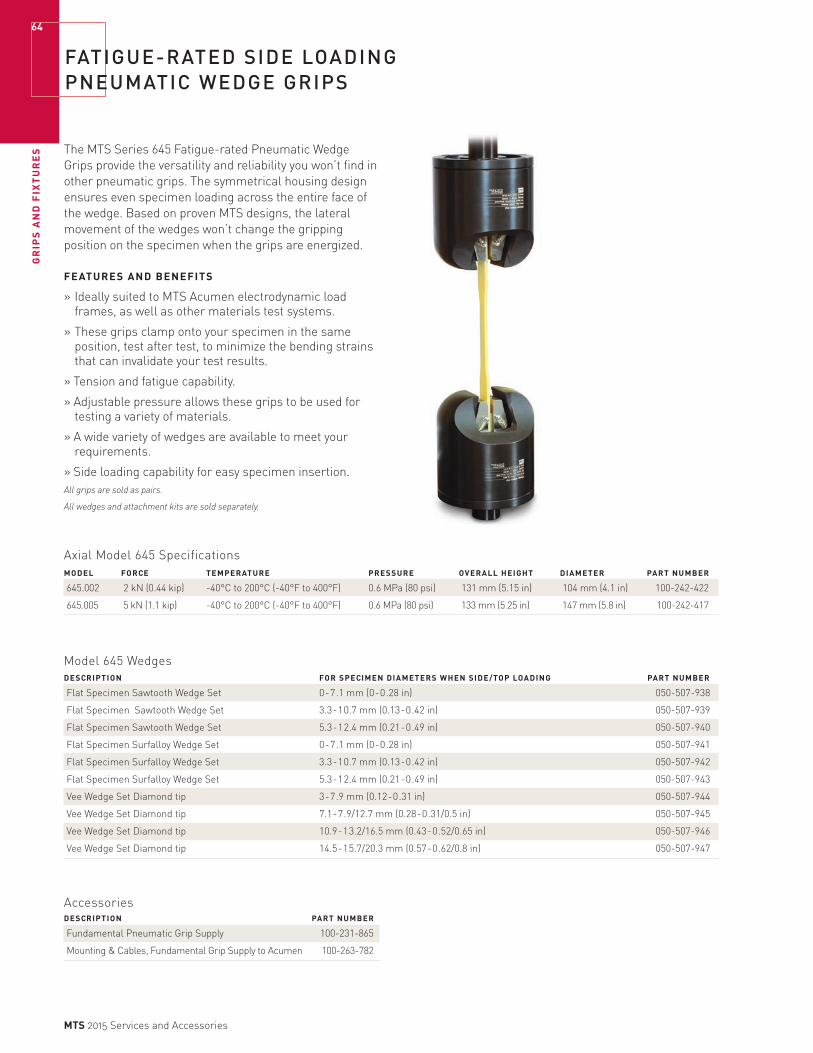
GR
IPS
AN
D F
IXT
UR
ES
64
MTS 2015 Services and Accessories
FATIGUE-RATED SIDE LOADING PNEUMATIC WEDGE GRIPS
The MTS Series 645 Fatigue-rated Pneumatic Wedge Grips provide the versatility and reliability you won’t find in other pneumatic grips. The symmetrical housing design ensures even specimen loading across the entire face of the wedge. Based on proven MTS designs, the lateral movement of the wedges won’t change the gripping position on the specimen when the grips are energized.
FEATURES AND BENEFITS
» Ideally suited to MTS Acumen electrodynamic load frames, as well as other materials test systems.
» These grips clamp onto your specimen in the same position, test after test, to minimize the bending strains that can invalidate your test results.
» Tension and fatigue capability.
» Adjustable pressure allows these grips to be used for testing a variety of materials.
» A wide variety of wedges are available to meet your requirements.
» Side loading capability for easy specimen insertion. All grips are sold as pairs.
All wedges and attachment kits are sold separately.
Axial Model 645 SpecificationsMODEL FORCE TEMPERATURE PRESSURE OVERALL HEIGHT DIAMETER PART NUMBER
645.002 2 kN (0.44 kip) -40°C to 200°C (-40°F to 400°F) 0.6 MPa (80 psi) 131 mm (5.15 in) 104 mm (4.1 in) 100-242-422
645.005 5 kN (1.1 kip) -40°C to 200°C (-40°F to 400°F) 0.6 MPa (80 psi) 133 mm (5.25 in) 147 mm (5.8 in) 100-242-417
Model 645 WedgesDESCRIPTION FOR SPECIMEN DIAMETERS WHEN SIDE/TOP LOADING PART NUMBER
Flat Specimen Sawtooth Wedge Set 0-7.1 mm (0-0.28 in) 050-507-938
Flat Specimen Sawtooth Wedge Set 3.3-10.7 mm (0.13-0.42 in) 050-507-939
Flat Specimen Sawtooth Wedge Set 5.3-12.4 mm (0.21-0.49 in) 050-507-940
Flat Specimen Surfalloy Wedge Set 0-7.1 mm (0-0.28 in) 050-507-941
Flat Specimen Surfalloy Wedge Set 3.3-10.7 mm (0.13-0.42 in) 050-507-942
Flat Specimen Surfalloy Wedge Set 5.3-12.4 mm (0.21-0.49 in) 050-507-943
Vee Wedge Set Diamond tip 3-7.9 mm (0.12-0.31 in) 050-507-944
Vee Wedge Set Diamond tip 7.1-7.9/12.7 mm (0.28-0.31/0.5 in) 050-507-945
Vee Wedge Set Diamond tip 10.9-13.2/16.5 mm (0.43-0.52/0.65 in) 050-507-946
Vee Wedge Set Diamond tip 14.5-15.7/20.3 mm (0.57-0.62/0.8 in) 050-507-947
AccessoriesDESCRIPTION PART NUMBER
Fundamental Pneumatic Grip Supply 100-231-865
Mounting & Cables, Fundamental Grip Supply to Acumen 100-263-782
GR
IPS
AN
D F
IXT
UR
ES
65
MTS 2015 Services and Accessories
ALIGNMENT FIXTURE, SOFTWARE, AND STRAIN-GAGED SPECIMENS SAVE TIME AND GET BETTER DATA
Alignment Software for up to 12-Gage SpecimensMTS Alignment hardware and software acquires, analyzes, and displays bending strains for alignment and bending strain verification purposes. Its graphical interface quickly allows you to align your system or to verify how much bending strain you currently have. One of the key attributes of this software is that it can separate the bending strain of the specimen from that of the load train.
The best method of determining bending strain is to use a strain-gaged specimen. This product interfaces directly with a strain-gaged specimen and displays bending strain graphically on the screen of your PC. Continual scanning of bending strains allows you to align your system or verify the bending strain while cycling load. When finished, an Excel report can be generated to certify your system.
Features» Supports 12-gage specimens for best results. Also
accommodates 4, 6, 8, and 9 gage specimens.
» Data aquisitioning and conditioning is external to the PC. This allows for much more PC flexibility, including laptops.
» This alignment system ensures compliance with industry standards: ASTM E1012, GES400 (NADCAP), GE450 and ISOTC 164SC5WG11.
» The “Alignment Wizard” verbally instructs the user how to perform concentric and angular adjustments.
» Accepts a calibrated load signal for a bending percent and bending strain versus load validation graph.
» Separates the specimen eccentricities from the system alignment.
Alignment FixtureThe MTS Model 609 Alignment Fixture for material testing systems saves time compared to manual alignment methods.
The main feature of the Model 609 Alignment Fixture is its capability to perform alignment adjustments while the load train is fully preloaded. This eliminates any inaccuracies involved in trying to account for the small changes in alignment that frequently occur during the preloading process.
In addition, because the fixture remains preloaded at all times, previous alignment adjustments are not lost when small changes in alignment are required.
The Model 609 Alignment Fixtures are compatible with MTS load frames. The alignment fixtures are also readily adaptable to other load frames.*
*New in FY14 Watch for Acumen alignment fixture.
GR
IPS
AN
D F
IXT
UR
ES
66
MTS 2015 Services and Accessories
Specimens for Alignment UseMTS offers round and flat standardized strain-gaged specimens for alignment use. Each specimen has 12 gages so you can correct both concentric and angular misalignments.
The gages are bonded with oven-cured epoxy for long life and are covered to prevent damage from handling. The specimen material is 4340 steel and is heat treated to safely allow stresses to 413 MPa (60,000 psi).
Alignment Fixture (for MTS load frames Model 318 and 312) LOAD FRAME STUD METRIC US CUSTOMARY
MODEL FORCE CAPACITY HEIGHT DIAMETER SIZE/LENGTH PART NUMBER PART NUMBER
609.02A-01 25 kN (5.5 kip) 72 mm (2.81 in) 121 mm (4.75 in) M12 x 1.25/355 mm (1/2”-20/14.0 in) 049-083-402 049-083-401
609.10A-01 100 kN (22 kip) 72 mm (2.81 in) 121 mm (4.75 in) M27 x 2/343 mm (1”-14/13.5 in) 049-083-502 049-083-501
609.25A-01 250 kN (55 kip) 80 mm (3.12 in) 162 mm (6.38 in) M36 x 2/462 mm (1 1/2”-12/18.2 in) 049-083-602 049-083-601
609.50A-01 500 kN (110 kip) 181 mm (7.11 in) 254 mm (10 in) M52 x 2/686 mm (2”-12/27 in) 051-499-202 051-499-201
*To add a Model 609 Alignment Fixture to a MTS Model 370 Load Frame, contact MTS.
REQUIRED ADAPTER KIT ORDERING INFORMATION FORTHE MODEL 609 ALIGNMENT FIXTURE (FOR LOAD FRAMES OTHER THAN MTS’ MODELS 370, 318, AND 312)
A Load cell thread size
B Load cell thread depth
C Crosshead height
D Crosshead through-hole diameter
E Dimensional information of any counter-bores in either the top or bottom of the crosshead
SPECIMENS PART NUMBER
Round (Metric) 056-651-703
Round (US Customary) 056-651-701
Flat 056-651-702
709.20E ALIGNMENT DATA ACQUISITION AND CONDITIONING UNITS
CERTIFIED VOLTAGE/PLUG PART NUMBER PART NUMBER
115 V AC, CE 057-677-601 057-677-606
230 V AC, US Plug, CE 057-677-602 057-677-607
230 V AC, Euro Plug, CE 057-677-603 057-677-608
230 V AC, China Plug, CE 057-677-605 057-677-610
For other plug options, contact MTS
ALIGNMENT SOFTWARE* PART NUMBER
709.20E-03 Alignment Software Perpetual License 056-866-201
709.20E-04 Alignment Software Annual License 056-866-202
709.20E-05 Alignment Software 5 year Term Annual Renewable License 056-866-203
*Requires XP/Vista/Windows 7.
ROUND SPECIMEN US CUSTOMARY FLAT SPECIMEN
ROUND SPECIMEN METRIC
200 mm
6 mm
52.8 mm
63.5 mm
12 mm
8”
1/4”
1 3/4”
2 1/2”
1/2” 1”
9”
1/2”
2”
2 1/4”
0.25” Thick
CROSSHEAD
LOAD CELLS
E
DC
B
A
MODEL 609 ALIGNMENT FIXTURE

GR
IPS
AN
D F
IXT
UR
ES
67
MTS 2015 Services and Accessories
HIGH-TEMPERATURE LCF GRIPS
MTS Model 680 High-Temperature Grips were expressly designed for high-temperature, low-cycle fatigue testing, but can also be used for other types of tension-compression or tension-only testing. The grip heads and extension rods are constructed of high-temperature, super alloys selected to extend into the heated zone of the furnace, minimizing the thermal gradients within the specimen. Accessories for these grips include a hand pump (required), your choice of buttonhead or threaded specimen adapters, and a water cooling kit.
MODEL DESCRIPTION TEMPERATURE RATING* MOUNTING PART NUMBER
680.01B-01 High-Temperature Grip Up to 1000°C (1800°F) M27 x 2 or 1”-14 044-057-103
* Force rating varies with temperature higher than 700°C (1290°F).
AccessoriesTYPE PART NUMBER
Hand Pump (Required) 100-254-832
Water Cooling Kit, with flow switches 057-697-502
Replacement Seal Kit 040-985-901
SPECIMEN ADAPTERS DIMENSIONS PART NUMBER
Buttonhead 0.25 in dia. shank, 041-901-902
0.75-0.85 in dia. button
Buttonhead 0.40 in dia. shank 041-901-904
0.75-0.85 in dia. button
Buttonhead 0.50 in dia. shank, 041-901-901
0.75-0.85 in dia. button
Buttonhead 12 mm dia. shank, 041-901-903
21.1-21.6 mm dia. button
Threaded 1/2 in-13 UNC-2B 041-901-801
Threaded M12 x1.75 mm 041-901-802
GR
IPS
AN
D F
IXT
UR
ES
68
MTS 2015 Services and Accessories
GRIP SUPPLIES AND INTENSIFIERS
MTS Model 685 self-contained, hydraulic Grip Supplies have been engineered for both performance and ease of use. There are two grip supplies and one grip intensifier to choose from.
STANDARD FEATURES INCLUDE:» Directional control value for each grip
» Center valve detent, allowing unparalleled control over gripping.
» Continuous positive pressure design, providing high pressure stability over the entire operating range.
» Separate flow control valve for control of grip engagement speed.
» Independent grip circuits eliminate crosstalk.
» Easy to maintain and service.
» Accommodate a wide range of electrical connections
MODEL 685.22 AND MODEL 685.10 STAND ALONE HYDRAULIC GRIP SUPPLIESThe 685.22 and 685.10 units feature a self-contained hydraulic pump, a 0.75 kW (1 hp) electric motor, a 11.3 l (3 gal) reservoir, a 10-micron absolute return line filter, and hoses for connection to grips. These units are furnished with individual directional control valves for upper and lower grips. The grip supplies use a special hydraulic fluid which allows the grips to be used in environmental chambers at elevated temperatures. They are designed to run continuously, which results in good pressure stability and easy adjustment of the output pressure. Grip closure rate is also adjustable. Since the grip supplies are self-contained systems, they allow the use of hydraulic grips on non-hydraulic test systems.
MODEL 685.60 HYDRAULIC GRIP INTENSIFIERThe 685.60 Hydraulic Grip Intensifier, which utilizes an innovative fluid-to-fluid intensification system, is used with grips that require a pressure higher than the normal system hydraulic pressure. Two versions are available with factory adjusted output pressures of 45 MPa (6,500 psi) and 69 MPa (10,000 psi). The output pressure is adjustable from 10 MPa (1,500 psi) up to the grip supply output rating.
To minimize the set-up time of larger grips, a high volume upgrade kit is available.

GR
IPS
AN
D F
IXT
UR
ES
69
MTS 2015 Services and Accessories
GRIP SUPPLIES AND INTENSIFIER SPECIFICATIONS
44.45 cm(17.5 in)
43.18 cm(17 in)
91.44 cm(36 in)
FILTRATION» 10 micron
HYDRAULIC FLUID» Mobile 525 SHC
(685.10 & 685.22)
MAXIMUM AMBIENT TEMPERATURE» 32° C (90° F)
DIMENSIONS (SEE PHOTO)» Depth: 43.18 cm (17 in)
» Width: 44.45 cm (17.5 in)
» Height: 91.44 cm (36 in)
ELECTRICAL PRESSURE SETTING OPERATIING POWER PARTMODEL** DESCRIPTION RANGE REPEATABILITY TEMPAERATURE WEIGHT REQUIREMENTS NUMBER
685.10E-05 Stand-alone 10-70 MPa ±0.7 MPa -40 to 177°C 76 kg 115 V 057-509-601 grip supply (1,500-10,000 psi) (±100 psi) (-40 to 350°F) (170 lb) (60 Hz)
685.10E-06 Stand-alone 10-70 MPa ±0.7 MPa -40 to 177°C 76 kg 100-115 V 057-509-602 grip supply (1,500-10,000 psi) (±100 psi) (-40 to 350°F) (170 lb) (50 Hz)
685.10E-07 Stand-alone 10-70 MPa ±0.7 MPa -40 to 177°C 76 kg 208-230 V 057-509-603 grip supply (1,500-10,000 psi) (±100 psi) (-40 to 350°F) (170 lb) (60 Hz)
685.10E-08 Stand-alone 10-70 MPa ±0.7 MPa -40 to 177°C 76 kg 200-240 V 057-509-604 grip supply (1,500-10,000 psi) (±100 psi) (-40 to 350°F) (170 lb) (50 Hz)
685.22D-05 Stand-alone 0.7-21 MPa ±0.07 MPa -40 to 177°C 76 kg 115 V 057-598-001 grip supply (100-3,000 psi) (±10 psi) (-40 to 350°F) (170 lb) (60 Hz)
685.22D-06 Stand-alone 0.7-21 MPa ±0.07 MPa -40 to 177°C 76 kg 100-115 V 057-598-002 grip supply (100-3,000 psi) (±10 psi) (-40 to 350°F) (170 lb) (50 Hz)
685.22D-07 Stand-alone 0.7-21 MPa ±0.07 MPa -40 to 177°C 76 kg 208-230 V 057-598-003 grip supply (100-3,000 psi) (±10 psi) (-40 to 350°F) (170 lb) (60 Hz)
685.22D-08 Stand-alone 0.7-21 MPa ±0.07 MPa -40 to 177°C 76 kg 200-240 V 057-598-004 grip supply (100-3,000 psi) (±10 psi) (-40 to 350°F) (170 lb) (50 Hz)
685.60C-02* Hydraulic system 10-45 MPa ±0.7 MPa -18 to 66°C 39 kg – 057-597-901 intensifier (1,500-6,500 psi) (±100 psi) (0 to 150°F) (87 lb)
685.60C-03* Hydraulic system 10-70 MPa ±0.7 MPa -18 to 66°C 39 kg – 057-597-902 intensifier (1,500-10,000 psi) (±100 psi) (0 to 150°F) (87 lb)
*Optional kit available to minimize set-up time of larger grips.**Pressure Stability: ±100 psi (1% of operating range). Continuous pump operation.

GR
IPS
AN
D F
IXT
UR
ES
70
MTS 2015 Services and Accessories
FRACTURE MECHANICS CLEVIS GRIPS
The MTS Model 640.20B Fracture Mechanics Grips are manufactured per ASTM E-399 specifications. They are the most popular grips used for fracture toughness and fatigue crack growth rate tests. They are constructed from high-strength, aircraft-quality 4340 steel and are machined to the exacting tolerances required by ASTM. The package includes two grips, two .4W pins, and four spring retainers.
SPECIMEN STATIC PIN MOUNTING MODEL WIDTH FORCE DIAMETER THREAD
640.20B-X1 12.7 mm (0.50 in) 60 kN (13.6 kip) 12.2 mm (0.48 in) M27 x 2 (1”-14)
640.20C-X3 25.4 mm (1.00 in) 60 kN (13.6 kip) 12.2 mm (0.48 in) M27 x 2 (1”-14)
Temperature Rating -129°C to 177°C METRIC MODEL PART NUMBER
640.20B-21 007-172-745
640.20C-03 007-172-743
Temperature Rating -200°F to 350°F
US CUSTOMARY MODEL PART NUMBER
640.20B-01 007-172-741
640.20C-03 007-172-743
HYDRAULIC GRIP CONTROL KIT
Load Frame Mounted Grip Control UnitThe MTS Model 685.53 Grip Control Unit accurately controls pressure to hydraulic grips. Each grip can be actuated independently. The kit includes the grip control unit, hydraulic hoses to the hydraulic power supply, hydraulic hoses to the grips, and a universal mounting bracket. The control unit requires 21 MPa (3,000 psi) input pressure and can control the pressure to the grips from 0.7 MPa to 20 MPa (100 psi to 3,000) psi with a resolution of ±0.07 MPa (±10 psi). This range and resolution allow the user to select the proper grip pressure so it holds the specimen sufficiently without damaging it. The stability of the controlled pressure is ±0.5 MPa (±25 psi) yielding no extraneous load fluctuations within your test. The clamping speed of the grips is also adjustable.
LOAD FRAME PRESSURE USED FOR GRIP PART MODEL (COLOR) CAPACITY MODEL NUMBERS NUMBER
685.53A-01* Load Frame Mounted 21 MPa /3,000 psi 647.02/.10 044-667-001 Grip Control (brown)
685.53C-02 Load Frame Mtd. Grip 21 MPa /3,000 psi 647.02/.10 050-195-402 Control 318.10/.25 (gray)
* JIC 6 drain hose is required if 318 load frame does not have lift and locks.

GR
IPS
AN
D F
IXT
UR
ES
71
MTS 2015 Services and Accessories
HIGH QUALITY BEND FIXTURES
MTS Model 642 Bend Fixtures are configured to meet a variety of testing requirements. The fixtures have adjustable spans with easy-to-use, permanently attached scales for equal positioning of the rollers. The hardened
MODEL 642.001» 1, 2, 3, 4, and 5 mm
rollers are included.
» Adjustable spans.
» Metric and US Customary scales.
MODELS 642.01 AND 642.10:» Meet ASTM D-790 flex test and ASTM D-2344 short
beam shear test requirements.
» Model 642.10 also meets ASTM E399.
» Flexible configurations provide either a region of constant stress or a line of maximum stress.
» Adjustable spans
» Metric and US Customary scales
MODEL 642.25:» Well-suited for ASTM E-399
fracture toughness tests, plastics tests (ASTM D-790 flex test), and composites tests (ASTM D-2344, short beam shear).
» Adjustable spans.
» Metric and US Customary scales.
DYNAMIC TEMPERATURE COMBINED PART MODEL DESCRIPTION LOWER FIXTURE SPAN FORCE* RANGE HEIGHT** NUMBER
642.001 3 & 4 point bend fixture 14-60 mm (0.6-2.4 in) 0.9 kN (200 lbf) -129°C to 149°C (-200°F to 300°F) 61 mm (2.4 in) 100-027-125
642.01A-01 3 point bend fixture 24-152 mm (0.94-6.0 in) 10 kN (2.2 kip) -129°C to 149°C (-200°F to 300°F) 172 mm (6.8 in) 051-427-701
642.01A-02 3 & 4 point bend fixture 24-152 mm (0.94-6.0 in) 10 kN (2.2 kip) -129°C to 149°C (-200°F to 300°F) 243 mm (9.6 in) 051-427-801
642.10B-01 3 point bend fixture 38-305 mm (1.5-12.0 in) 100 kN (22 kip) -129°C to 177°C (-200°F to 350°F) 273 mm (10.75 in) 050-032-601
642.10B-02 3 & 4 point bend fixture 38-305 mm (1.5-12.0 in) 100 kN (22 kip) -129°C to 177°C (-200°F to 350°F) 356 mm (14.00 in) 050-032-701
642.25B-01 3 point bend fixture 79-610 mm (3.12-24.0 in) 250 kN (55 kip) -129°C to 177°C (-200°F to 350°F) 470 mm (18.50 in) 050-876-201
642.25B-02 3 & 4 point bend fixture 79-610 mm (3.12-24.0 in) 250 kN (55 kip) -129°C to 177°C (-200°F to 350°F) 660 mm (26.00 in) 050-876-301
*Static and dynamic force rating depends upon roller diameter. **Dimension depends upon roller diameter. Largest roller diameter shown.
Model 642.01 Roller Assemblies*
SIZE PART NUMBER
5 mm 051-284-601
10 mm 051-284-603
0.25 in 051-284-602
0.50 in 051-284-604
Model 642.10 Roller Assemblies*
PART PART SIZE NUMBER SIZE NUMBER
5 mm 049-578-501 0.25 in 049-578-502
10 mm 049-578-503 0.375 in 049-578-510
15 mm 049-578-505 0.50 in 049-578-504
20 mm 049-578-507 0.75 in 049-578-506
25 mm 049-578-509 1.00 in 049-578-508
Model 642.25 Roller Assemblies* PART PART SIZE NUMBER SIZE NUMBER
20 mm 050-875-202 0.75 in 050-875-201
30 mm 050-875-204 1.00 in 050-875-203
40 mm 050-875-207
50 mm 050-875-209
*Includes one roller and attachment springs.Order quantity 3 for 3-point bend and 4 for 4-point bend configurations.Roller assemblies listed above are not included with bend fixtures and must be purchased separately.
rollers ensure test result accuracy by reducing undesirable loading and frictional forces on the specimen. All models can be used for both 3- and 4-point tests.
GR
IPS
AN
D F
IXT
UR
ES
72
MTS 2015 Services and Accessories
COMPRESSION PLATENS
MODEL 643 COMPRESSION PLATENSMTS Model 643 Compression Platens are made from case-hardened alloy steel with hard chrome plating. The platens have a smooth face with etched concentric rings, enabling the specimen to be centered visually for better test results. The upper platen is available with a spherical seat for improved alignment and ensuring even pressure across the entire surface of the specimen. Model 643 compression platens are offered in three configurations: Fixed & Spherical, Two Fixed, and One Fixed.
Units range in diameter from 60 mm (2.4 in) to 300 mm (12 in) and are designed for a unit stress of 689 MPa (100,000 psi) static (275 MPa (40,000 psi) dynamic) centered on the bearing surfaces. The usable temperature range is -129°C to 177°C (-200°F to +350°F).
Specifications MAX. SPECIMEN MOUNTING THREAD MODEL DIAMETER INSERT SIZES
643.06B 60 mm (2.4 in) M12 x 1.25 /1/2”-20
643.10B 100 mm (4 in) M27 x 2 /1”-14
643.15B 150 mm (6 in) M27 x 2 /1”-14
643.20B 200 mm (8 in) M27 x 2 /1”-14
643.30B 300 mm (12 in) M52 x 2 /2”-12
MODEL DESCRIPTION PART NUMBER
643.06B-01 Fixed & Spherical 050-292-603
643.06B-03 Two Fixed 050-292-503
643.06B-05 One Fixed 050-612-103
643.10B-01 Fixed & Spherical 050-292-803
643.10B-03 Two Fixed 050-292-703
643.10B-05 One Fixed 050-612-203
643.15B-01 Fixed & Spherical 050-293-003
643.15B-03 Two Fixed 050-292-903
643.15B-05 One Fixed 050-612-303
643.20B-01 Fixed & Spherical 053-042-503
643.20B-03 Two Fixed 053-042-803
643.20B-05 One Fixed 053-042-703
643.30B-01 Fixed & Spherical 050-293-203
643.30B-03 Two Fixed 050-293-103
643.30B-05 One Fixed 050-612-403

GR
IPS
AN
D F
IXT
UR
ES
73
MTS 2015 Services and Accessories
A COMPREHENSIVE ARRAY OF ELECTROMECHANICAL ACCESSORIES
MTS complements its electromechanical testing lines with a comprehensive array of accessories to fulfill a full spectrum of material and small component testing—from basic quality control, to complex biomedical simulations, to demanding research and development applications. This array comprises three distinct accessory families to accommodate your specific and evolving testing needs:
MTS Advantage AccessoriesHighly versatile and full-featured wedge, pneumatic, and screw action grips for demanding R&D testing of advanced composites and alloys. Ideal for the specific needs of the high-end researcher, this accessory family accommodates a very broad range of clamping force and temperature requirements and features numerous control and grip face options. MTS stands behind the MTS Advantage family line with a three-year warranty—the best in the industry!
MTS Fundamental Accessories A new family of basic, affordable grips and fixtures for standard testing of plastics, textiles, rubber, wire, rope, and more. These accessories feature a universal adapter design and optional threaded frame adapters to facilitate easy installation onto both MTS electromechanical and servohydraulic load frame systems, as well as other electromechanical test systems. Anti-rotation features and integrated alignment pins enhance test accuracy and repeatability.
Bionix Accessories Affordable and extremely durable grips, fixtures, and platens for accurately replicating biomaterial and medical device service environments and extending the utility of Bionix electromechanical and servohydraulic test solutions. These accessories feature a universal adapter design and optional threaded frame adapters. This facilitates easy installation onto both MTS electromechanical and servohydraulic load frame systems as well as other electromechanical test systems. Anti-rotation features and integrated alignment pins enhance test accuracy and repeatability.

GR
IPS
AN
D F
IXT
UR
ES
74
MTS 2015 Services and Accessories
10 N MTS ADVANTAGE PNEUMATIC GRIPS
Grips Ideal for Thin Strips, Wires and Films with Low Breaking StrengthThese 10 N capacity (2 lbf) pneumatic grips are designed for low tensile applications and work well on thin specimens with low breaking strengths like the gold wire in electronics, tungsten wire, thermocouples, gels, and plastic films.
A big advantage these grips have over other low capacity grips is that they have been designed and machined to precise tolerances, thereby eliminating side loads.
Other features include a lightweight design to let you test with your low-capacity load cells without the grips using up too much of its capacity. It also has a self-aligning feature which lets these grips check alignment even while actuated.
These grips feature dual acting, swivel faces. With dual action, both faces move simultaneously to the centerline of the grip and eliminate the bending strains on your specimen that can invalidate your test results. The ability to swivel lets these faces conform to any variation in your specimen’s geometry. The faces shown below are sold separately.
These pneumatic grips require an air supply to provide filtered, dry air and an air grip controller. They are compatible with servohydraulic and electromechanical test systems.
FEATURES» Designed with plenty of room to manipulate your
specimens.
» Swivel faces to accommodate varying specimen widths.
» No side loads to influence your specimen.
10 N (2 lbf) Pneumatic Grips CLAMPING MAX SPECIMEN UPPER GRIP TEMPERATURE RATING AIR PRESSURE FORCE THICKNESS WEIGHT PART NUMBER
-40°C to 200°C (-40°F to 400°F) 0.6 MPa (80 psi) 31 N (7 lbf) 5 mm (0.20 in) 270 g (9.6 oz) 100-032-017
Type Bm upper grip mounting, type Dm lower.
Faces** for 10 N (2 lbf) Pneumatic Grips
FACE SURFACE WIDTH HEIGHT PART NUMBER
Smooth 15 mm (0.60 in) 8 mm (0.30 in) 056-163-701
Serrated 15 mm (0.60 in) 8 mm (0.30 in) 056-163-702
Rubber* 15 mm (0.60 in) 8 mm (0.30 in) 056-163-703
* Room temperature only.** Refer to the TechNote on page 76 for guidance.
grip
X
Y
clevis pin connection type
Electromechanical Attachment SchemeCLEVIS PIN CONNECTION TYPE TYPE B TYPE C TYPE D 15 30
Load Up to 10 N Up to 200 N Up to 150 kN Up to 200 N Up to 150 kN
Clevis Diameter (X) 0.50 in 0.625 in 1.25 in 15 mm 30 mm
Pin Diameter (Y) 0.187 in 0.25 in 0.50 in 6 mm 14 mm
Upper Grip Connection (male) Bm Cm Dm 15 m 30 m
Lower Grip Connection (male) Dm Dm Dm 30 m 30 m
Upper Load Frame Connection (female) Bf Cf Df 15 f 30 f
Lower Load Frame Connection (female) Df Df Df 30 f 30 f

GR
IPS
AN
D F
IXT
UR
ES
75
MTS 2015 Services and Accessories
100/200 N AND 2 KN MTS ADVANTAGE PNEUMATIC GRIPS
Designed for testing thin sheets, films, and tapes, these 100/200 N and 2 kN (20/40 lbf and 400 lbf) pneumatic grips will let you perform tests with your low capacity load cells without taking up too much of your load cells capacity.
Both models feature dual acting grip faces that simultaneously move to the centerline of the grip. This assures correct specimen alignment and removes the bending strains that can invalidate your test results.
The design of both grips lets you quickly and easily load and align your specimens. This lets you spend less time loading specimens and more time testing. They also feature an area above the grip faces that is large enough for you to load the specimens while holding them with your fingers.
Both grips use standard pin connectors for the connection to the baseplate and load cells and can be used with servohydraulic or electromechanical test systems.
FEATURES» Lightweight design so you can perform low force tests
without using up too much of your low-capacity load cells capacity.
» Dual acting grip faces which move to the centerline of the grip for better specimen alignment.
» Large area above the grip faces so you can load your specimens while holding them with your fingers.
» Integrated clamp/release switch located close to the specimen for intuitive inspection.
These 100N (20 lbf) (top) and 2kN (400 lbf) (bottom) capacity pneumatic grips can be used to test a variety of thin films, sheets, and tapes. Grip faces are shown on the next page.
10 N (2 lbf) Pneumatic Grips MAXIMUM CLAMPING SPECIMEN DIMENSIONS UPPER GRIP PART DESCRIPTION FORCE THICKNESS TEMPERATURE RANGE HEIGHT WIDTH WEIGHT NUMBER
100/200 N (20/40 lbf) 620 N (140 lbf) 10 mm (0.39 in) -40°C to 100°C (-40°F to 212°F) 180 mm (7.1 in) 114 mm (4.5 in) 1.0 kg (2.0 lb) 100-036-576Pneumatic Grips*
2 kN (400 lbf) 7100 N (1600 lbf) 12 mm (0.47 in) -40°C to 200°C (-40°F to 400°F) 226 mm (8.9 in) 131 mm (5.2 in) 3.2 kg (7 lb) 100-280-342Pneumatic Grips**
* Type Cm upper grip mounting, type Dm lower. (See page 74)
** Type Dm upper grip mounting, type Dm lower. (See page 74)
Standard SpecificationsAIR PRESSURE
0.6 MPa (80 psi)

GR
IPS
AN
D F
IXT
UR
ES
76
MTS 2015 Services and Accessories
100/200 N AND 2 KN MTS ADVANTAGE GRIPS FACES
Faces for the 100/200 N and 2 kN (20/40 lbf and 400 lbf) capacity pneumatic grips are available with a variety of surface coatings so you can use your grips to test a variety of materials.
To find out more about which surface works best on the material you’re testing, read the TechNote on this page.
The 100/200 N and 2 kN (20/40 lbf and 400 lbf) capacity grips share the same faces and are sold in sets of four.
Faces for 100/200 N and 2 kN (20/40 lbf and 400 lbf) Pneumatic Grips FACE SURFACE HEIGHT WIDTH PART NUMBER
Rubber (smooth)* 12.5 mm (0.5) 25 mm (1 in) 056-163-825
Smooth 25 mm (1 in) 25 mm (1 in) 056-163-801
Corrugated 25 mm (1 in) 25 mm (1 in) 056-163-802
Serrated 25 mm (1 in) 25 mm (1 in) 056-163-803
Diamond Tip 25 mm (1 in) 25 mm (1 in) 056-163-804
Rubber (matte)* 25 mm (1 in) 25 mm (1 in) 056-163-805
Rubber (corrugated)* 25 mm (1 in) 25 mm (1 in) 056-163-806
Rubber (smooth)* 25 mm (1 in) 25 mm (1 in) 056-163-807
Line Contact (r=4.75 mm) 25 mm (1 in) 25 mm (1 in) 056-163-808
Line Contact w/Rubber Opposite* (r=4.75 mm) 25 mm (1 in) 25 mm (1 in) 056-163-826
Line Contact w/Rubber Opposite* (r=2.5 mm) 25 mm (1 in) 25 mm (1 in) 056-163-829
Smooth 25 mm (1 in) 75 mm (3 in) 056-163-809
Corrugated 25 mm (1 in) 75 mm (3 in) 056-163-810
Serrated 25 mm (1 in) 75 mm (3 in) 056-163-811
Diamond Tip 25 mm (1 in) 75 mm (3 in) 056-163-812
Rubber (matte)* 25 mm (1 in) 75 mm (3 in) 056-163-813
Rubber (corrugated)* 25 mm (1 in) 75 mm (3 in) 056-163-814
Rubber (smooth)* 25 mm (1 in) 75 mm (3 in) 056-163-815
Diamond 25 mm (1 in) 150 mm (5.9 in) 056-163-828
Rubber* 25 mm (1 in) 150 mm (5.9 in) 056-163-830
Smooth 38 mm (1.5 in) 58 mm (2.3 in) 056-163-816
Corrugated 38 mm (1.5 in) 58 mm (2.3 in) 056-163-817
Serrated 38 mm (1.5 in) 58 mm (2.3 in) 056-163-818
Diamond Tip 38 mm (1.5 in) 58 mm (2.3 in) 056-163-819
Rubber (matte)* 38 mm (1.5 in) 58 mm (2.3 in) 056-163-820
Rubber (corrugated)* 38 mm (1.5 in) 58 mm (2.3 in) 056-163-821
Rubber (smooth-EPDM)* 38 mm (1.5 in) 58 mm (2.3 in) 056-163-822
Line Contact (r=4.75 mm) 38 mm (1.5 in) 58 mm (2.3 in) 056-163-823
Line Contact w/Rubber Opposite* (r=4.75 mm) 38 mm (1.5 in) 58 mm (2.3 in) 056-163-827
Grab Test 38 mm (1.5 in) 58 mm (2.3 in) 056-163-824
* Rubber grip faces are for use only at room temperature. Rubber faces can be reconditioned. Contact Order Services.
T E C H N O T E
Choosing the Right Surface
IMPROVE YOUR TEST RESULTS
Grip-induced failure and slippage can cost you time and money, so it’s important to pick out the right faces or the material you’re testing. MTS manufactures faces for our pneumatic grips with a variety of surfaces to accommodate your specimen. Here’s a brief description of the surfaces offered:
• Corrugated (top left) for smooth specimens (textile, fabrics, tissue, leather).
• Serrated (top right) for gripping soft materials without causing failure (paper, board, aluminum, copper and steel wire, soft steels).
• Rubber Coated (black colored) to offer extra protection for your thin specimens (films, fibers, aluminum).
• Diamond Tipped (bottom right) to provide you with an aggressive surface for gripping soft materials (soft steels, rigid plastic, wood).
• Grab Test (center) according to international standards, including ASTM D2208 (leather), D5034 (fabrics), D1683 (woven fabrics) and ISO 5082 (fabrics).
• Line Contact (bottom left) faces are for rubber, latex, and cable sheath.
Faces are also available in a wide width for some grip models.
All of the faces for the grips in this catalog are sold in sets of four.

GR
IPS
AN
D F
IXT
UR
ES
77
MTS 2015 Services and Accessories
10 KN MTS ADVANTAGE PNEUMATIC GRIP
The 10 kN (2.2 kip) capacity pneumatic grips are designed for performing tensile tests on a variety of materials including elastomers, plastics, rigid and semi-rigid films, and sheets.
These grips feature dual acting grip faces that simultaneously move to the centerline of the grip. This feature assures correct specimen alignment and removes the bending strains on your specimens that can invalidate test results.
In addition to these two unique features, these grips save you time by offering quick and easy specimen insertion. This lets you spend less time inserting and aligning specimens and more time testing. Both models also feature a constant clamping load to protect your specimens from damage due to slippage.
A pneumatic controller (see below), available with foot-control to free up both hands for more accurate specimen alignment, and an air supply to provide dry, filtered air are required to operate these grips. The 10 kN MTS Advantage Pneumatic grips share the same faces as the Model 647.02B, which can be found on page 59. They are available for flat, round, or vee specimens with a variety of surfaces. They can be used with servohydraulic or electromechanical test systems.
MTS ADVANTAGE PNEUMATIC GRIP CONTROLLERSThis controller provides an open/close function, air pressure regulation, and flow control for pneumatic grips.
To make specimen loading hassle-free, the unit comes with a magnetic-mount handset or optional footswitch. The handset or footswitch sequence is user-selectable for adaptable and efficient specimen loading. The controller comes with 3.6 m (12 ft) of temperature-resistant Teflon® tubing for grip connections, and a 12 V power supply that will operate on voltages world-wide (90-264 V AC, 47-63 Hz). The system is CE compliant.
FEATURES» Dual acting grip faces which move to the centerline
of the grip for better specimen alignment.
» Easy specimen insertion to save time and a constant clamping load to protect your specimen from damage due to slippage.
Specifications
Temperature range: -40°C to 200°C (-40°F to 400°F)
Air pressure: 0.6 MPa (80 psi)
Upper grip mounting: Type Dm (See page 74)
Lower grip mounting: Type Dm (See page 74)
Specifications MAXIMUM CLAMPING SPECIMEN OVERALL UPPER GRIP PART DESCRIPTION FORCE THICKNESS HEIGHT WIDTH WEIGHT NUMBER
10 kN (2.2 kip) Pneumatic Grips 17 kN (4 kip) 10-20 mm (0.4-0.8 in) 183 mm (7.2 in) 200 mm (7.9 in) 7.3 kg (16 lb) 100-034-623
HANDSET CONFIGURATION (AS SHIPPED) » Press switch one to close grip one.
» Press switch one again to close grip two.
» Press switch two to open both grips. *Notes: Three other switch combinations are user-selectable. The optional footswitch is configured in the same way.
MAXIMUM DRY AIR MAXIMUM POWER PART/MODEL DESCRIPTION AIR INTAKE CONNECTION OUTPUT REQUIREMENTS NUMBER
Grip Controller and Handset 0.85 MPa (125 psi) 4 mm (5/32 in) tube 0.62 MPa (90 psi) 90-264 V AC, 47-63 Hz, 2.5 W 100-094-123
Footswitch (optional) 100-094-131
Air Supply Assembly 0.9 MPa (130 psi) 4 mm (5/32 in) tube 0.7 MPa (100 psi) N/A 100-041-199
(For Advantage Pneumatic Grips only)
MTS Advantage Pneumatic Grip Controller
Optional Footswitch
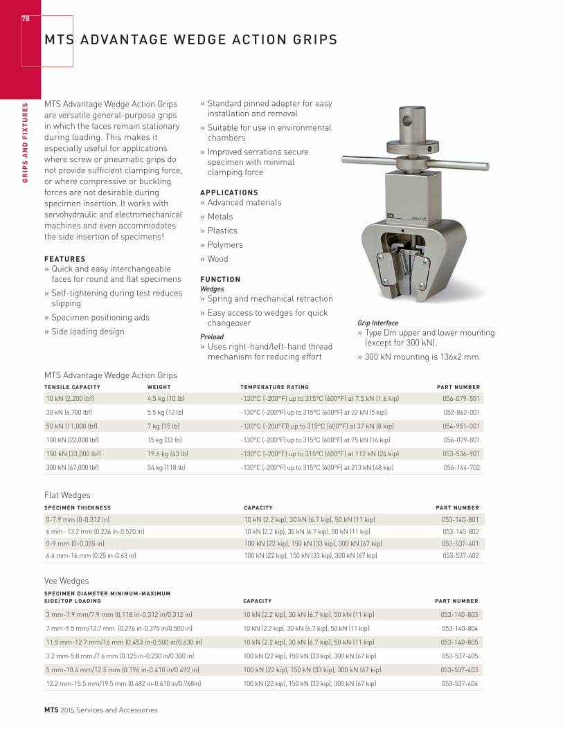
GR
IPS
AN
D F
IXT
UR
ES
78
MTS 2015 Services and Accessories
MTS ADVANTAGE WEDGE ACTION GRIPS
MTS Advantage Wedge Action Grips are versatile general-purpose grips in which the faces remain stationary during loading. This makes it especially useful for applications where screw or pneumatic grips do not provide sufficient clamping force, or where compressive or buckling forces are not desirable during specimen insertion. It works with servohydraulic and electromechanical machines and even accommodates the side insertion of specimens!
FEATURES» Quick and easy interchangeable
faces for round and flat specimens
» Self-tightening during test reduces slipping
» Specimen positioning aids
» Side loading design
MTS Advantage Wedge Action GripsTENSILE CAPACITY WEIGHT TEMPERATURE RATING PART NUMBER
10 kN (2,200 lbf) 4.5 kg (10 lb) -130°C (-200°F) up to 315°C (600°F) at 7.5 kN (1.6 kip) 056-079-501
30 kN (6,700 lbf) 5.5 kg (12 lb) -130°C (-200°F) up to 315°C (600°F) at 22 kN (5 kip) 052-862-001
50 kN (11,000 lbf) 7 kg (15 lb) -130°C (-200°F)) up to 315°C (600°F) at 37 kN (8 kip) 054-951-001
100 kN (22,000 lbf) 15 kg (33 lb) -130°C (-200°F) up to 315°C (600°F) at 75 kN (16 kip) 056-079-801
150 kN (33,000 lbf) 19.6 kg (43 lb) -130°C (-200°F) up to 315°C (600°F) at 112 kN (24 kip) 053-536-901
300 kN (67,000 lbf) 54 kg (118 lb) -130°C (-200°F) up to 315°C (600°F) at 213 kN (48 kip) 056-144-702
» Standard pinned adapter for easy installation and removal
» Suitable for use in environmental chambers
» Improved serrations secure specimen with minimal clamping force
APPLICATIONS» Advanced materials
» Metals
» Plastics
» Polymers
» Wood
FUNCTIONWedges» Spring and mechanical retraction
» Easy access to wedges for quick changeover
Preload» Uses right-hand/left-hand thread
mechanism for reducing effort
Flat WedgesSPECIMEN THICKNESS CAPACITY PART NUMBER
0-7.9 mm (0-0.312 in) 10 kN (2.2 kip), 30 kN (6.7 kip), 50 kN (11 kip) 053-140-801
6 mm- 13.2 mm (0.236 in-0.520 in) 10 kN (2.2 kip), 30 kN (6.7 kip), 50 kN (11 kip) 053-140-802
0-9 mm (0-0.355 in) 100 kN (22 kip), 150 kN (33 kip), 300 kN (67 kip) 053-537-401
6.4 mm-16 mm (0.25 in-0.63 in) 100 kN (22 kip), 150 kN (33 kip), 300 kN (67 kip) 053-537-402
Vee WedgesSPECIMEN DIAMETER MINIMUM-MAXIMUM SIDE/TOP LOADING CAPACITY PART NUMBER
3 mm-7.9 mm/7.9 mm (0.118 in-0.312 in/0.312 in) 10 kN (2.2 kip), 30 kN (6.7 kip), 50 kN (11 kip) 053-140-803
7 mm-9.5 mm/12.7 mm (0.276 in-0.375 in/0.500 in) 10 kN (2.2 kip), 30 kN (6.7 kip), 50 kN (11 kip) 053-140-804
11.5 mm-12.7 mm/16 mm (0.453 in-0.500 in/0.630 in) 10 kN (2.2 kip), 30 kN (6.7 kip), 50 kN (11 kip) 053-140-805
3.2 mm-5.8 mm /7.6 mm (0.125 in-0.230 in/0.300 in) 100 kN (22 kip), 150 kN (33 kip), 300 kN (67 kip) 053-537-405
5 mm-10.4 mm/12.5 mm (0.196 in-0.410 in/0.492 in) 100 kN (22 kip), 150 kN (33 kip), 300 kN (67 kip) 053-537-403
12.2 mm-15.5 mm/19.5 mm (0.482 in-0.610 in/0.768in) 100 kN (22 kip), 150 kN (33 kip), 300 kN (67 kip) 053-537-404
Grip Interface» Type Dm upper and lower mounting
(except for 300 kN).
» 300 kN mounting is 136x2 mm
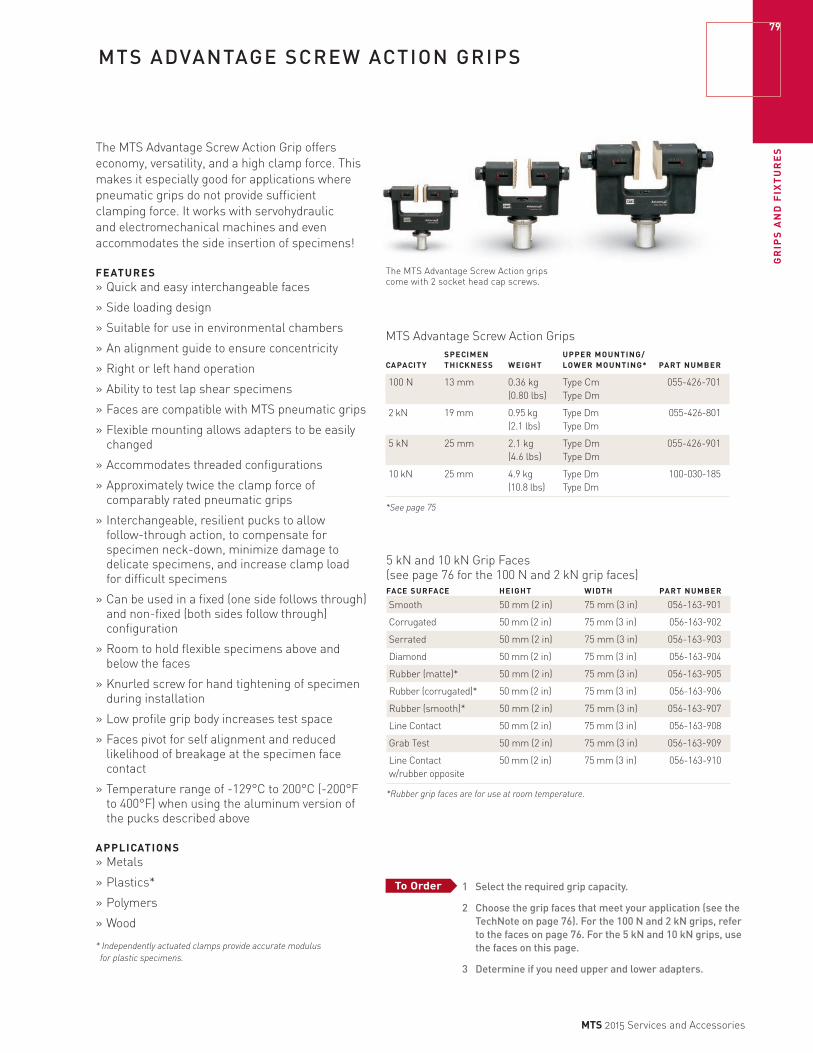
GR
IPS
AN
D F
IXT
UR
ES
79
MTS 2015 Services and Accessories
MTS ADVANTAGE SCREW ACTION GRIPS
The MTS Advantage Screw Action Grip offers economy, versatility, and a high clamp force. This makes it especially good for applications where pneumatic grips do not provide sufficient clamping force. It works with servohydraulic and electromechanical machines and even accommodates the side insertion of specimens!
FEATURES» Quick and easy interchangeable faces
» Side loading design
» Suitable for use in environmental chambers
» An alignment guide to ensure concentricity
» Right or left hand operation
» Ability to test lap shear specimens
» Faces are compatible with MTS pneumatic grips
» Flexible mounting allows adapters to be easily changed
» Accommodates threaded configurations
» Approximately twice the clamp force of comparably rated pneumatic grips
» Interchangeable, resilient pucks to allow follow-through action, to compensate for specimen neck-down, minimize damage to delicate specimens, and increase clamp load for difficult specimens
» Can be used in a fixed (one side follows through) and non-fixed (both sides follow through) configuration
» Room to hold flexible specimens above and below the faces
» Knurled screw for hand tightening of specimen during installation
» Low profile grip body increases test space
» Faces pivot for self alignment and reduced likelihood of breakage at the specimen face contact
» Temperature range of -129°C to 200°C (-200°F to 400°F) when using the aluminum version of the pucks described above
APPLICATIONS» Metals
» Plastics*
» Polymers
» Wood
* Independently actuated clamps provide accurate modulus
for plastic specimens.
MTS Advantage Screw Action Grips SPECIMEN UPPER MOUNTING/ CAPACITY THICKNESS WEIGHT LOWER MOUNTING* PART NUMBER
100 N 13 mm 0.36 kg Type Cm 055-426-701 (0.80 lbs) Type Dm
2 kN 19 mm 0.95 kg Type Dm 055-426-801 (2.1 lbs) Type Dm
5 kN 25 mm 2.1 kg Type Dm 055-426-901 (4.6 lbs) Type Dm
10 kN 25 mm 4.9 kg Type Dm 100-030-185 (10.8 lbs) Type Dm
*See page 75
The MTS Advantage Screw Action grips come with 2 socket head cap screws.
5 kN and 10 kN Grip Faces (see page 76 for the 100 N and 2 kN grip faces)
FACE SURFACE HEIGHT WIDTH PART NUMBER
Smooth 50 mm (2 in) 75 mm (3 in) 056-163-901
Corrugated 50 mm (2 in) 75 mm (3 in) 056-163-902
Serrated 50 mm (2 in) 75 mm (3 in) 056-163-903
Diamond 50 mm (2 in) 75 mm (3 in) 056-163-904
Rubber (matte)* 50 mm (2 in) 75 mm (3 in) 056-163-905
Rubber (corrugated)* 50 mm (2 in) 75 mm (3 in) 056-163-906
Rubber (smooth)* 50 mm (2 in) 75 mm (3 in) 056-163-907
Line Contact 50 mm (2 in) 75 mm (3 in) 056-163-908
Grab Test 50 mm (2 in) 75 mm (3 in) 056-163-909
Line Contact 50 mm (2 in) 75 mm (3 in) 056-163-910 w/rubber opposite
*Rubber grip faces are for use at room temperature.
1 Select the required grip capacity.
2 Choose the grip faces that meet your application (see the TechNote on page 76). For the 100 N and 2 kN grips, refer to the faces on page 76. For the 5 kN and 10 kN grips, use the faces on this page.
3 Determine if you need upper and lower adapters.
To Order

GR
IPS
AN
D F
IXT
UR
ES
80
MTS 2015 Services and Accessories
MTS FUNDAMENTAL VISE ACTION GRIPS
MTS Fundamental Vise Action Grips are value-priced miniature, medium, and heavy-duty general purpose tensile grips that use a clamping screw to tighten a vise; each order includes a set of rubber faces. Available in a variety of load capacities and sizes, they are suitable for testing paper, plastic film, textiles, sheet materials, and packaging components at temperatures ranging from -10°C to 50°C. These accessories feature a universal adapter design and an optional threaded frame adapter to facilitate easy installation onto both MTS electromechanical and servohydraulic load frame systems, as well as other electromechanical test systems. Anti-rotation features and integrated alignment pins enhance test accuracy and repeatability.
FEATURES» Set of rubber faces standard with each order
» Universal adapter design
» Optional threaded frame adapter (Type D standard)
» Anti-rotation features and integrated alignment pins
» Temperature range: -10°C to 50°C
» Applications: Paper, plastic film, textiles, sheet materials, packaging components
Model 100
Model 2000/5000
MTS Fundamental Vise Action Grips MAXIMUM MAXIMUM MAXIMUM SPECIMEN SPECIMEN WEIGHT HEIGHT MODEL LOAD FACE PROFILE THICKNESS WIDTH (UPPER) (FROM CLEVIS CENTER) PART NUMBER
100 100 N Rubber 2 mm 10 mm 254 g 100 mm 100-186-412
2000 2 kN Rubber 3.5 mm 63 mm 625 g 95 mm 100-174-781
5000 5 kN Rubber 10 mm 80 mm 2190 g 140 mm 100-186-414

GR
IPS
AN
D F
IXT
UR
ES
81
MTS 2015 Services and Accessories
MTS FUNDAMENTAL SCISSORS ACTION GRIPS
MTS Fundamental Scissors Action Grips are value-priced, self-tightening, and self-aligning grips featuring diamond faces. They are suitable for testing foil, rubber, and flexible polymers at temperatures ranging from -10°C to 50°C. These accessories feature a universal adapter design and an optional threaded frame adapter to facilitate easy installation onto both MTS electromechanical and servohydraulic load frames systems, as well as other electromechanical test systems. Anti-rotation features and integrated alignment pins enhance test accuracy and repeatability.
FEATURES
» Self-tightening and self-aligning» Diamond grip faces» Universal adapter design» Optional threaded frame adapter (Type D standard)» Anti-rotation features and integrated alignment pins» Temperature range: -10°C to 50°C» Applications: Foil, rubber, flexible polymers
MTS Fundamental Scissors Action Grips MAXIMUM MAXIMUM MAXIMUM SPECIMEN SPECIMEN WEIGHT HEIGHT (FROM MODEL LOAD THICKNESS WIDTH (UPPER) CLEVIS CENTER) PART NUMBER
5000 5 kN 15 mm 50 mm 2625 g 215 mm 100-181-624
MTS FUNDAMENTAL LOW FORCE ALUMINUM COMPRESSION PLATENSMTS Fundamental Low Force Aluminum Compression Platens are value-priced, lightweight fixed compression platens designed for testing with small load cells (1 kN and less). Available in a variety of sizes, they are suitable for testing polystyrene, rubber, composites, sintered materials, and components at temperatures ranging from -130°C to 150°C. These accessories feature a universal adapter design and an optional threaded frame adapter to facilitate easy installation onto both MTS electromechanical and servohydraulic load frame systems, as well as other electromechanical test systems. Specimen-centering grooves, anti-rotation features, and integrated alignment pins enhance test accuracy and repeatability.
FEATURES
» Universal adapter design
» Optional threaded frame adapter (Type D standard)» Specimen-centering grooves» Anti-rotation features and integrated alignment pins» Temperature range: -130°C to 150°C
» Applications: Polystyrene, rubber, composites, sintered materials, and components
MTS Fundamental Low Force Aluminum Compression Platens MAXIMUM SPECIMEN MAXIMUM HEIGHT (FROM
MODEL LOAD DIAMETER WEIGHT (UPPER) CLEVIS CENTER) PART NUMBER
150 1 kN 150 mm 1355 g 64 mm 100-182-224
Model 5000
Model 150
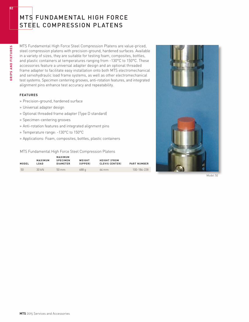
GR
IPS
AN
D F
IXT
UR
ES
82
MTS 2015 Services and Accessories
MTS FUNDAMENTAL HIGH FORCE STEEL COMPRESSION PLATENS
MTS Fundamental High Force Steel Compression Platens are value-priced, steel compression platens with precision-ground, hardened surfaces. Available in a variety of sizes, they are suitable for testing foam, composites, bottles, and plastic containers at temperatures ranging from -130°C to 150°C. These accessories feature a universal adapter design and an optional threaded frame adapter to facilitate easy installation onto both MTS electromechanical and servohydraulic load frame systems, as well as other electromechanical test systems. Specimen centering grooves, anti-rotation features, and integrated alignment pins enhance test accuracy and repeatability.
FEATURES
» Precision-ground, hardened surface
» Universal adapter design
» Optional threaded frame adapter (Type D standard)
» Specimen-centering grooves
» Anti-rotation features and integrated alignment pins
» Temperature range: -130°C to 150°C
» Applications: Foam, composites, bottles, plastic containers
MTS Fundamental High Force Steel Compression Platens MAXIMUM MAXIMUM SPECIMEN WEIGHT HEIGHT (FROM MODEL LOAD DIAMETER (UPPER) CLEVIS CENTER) PART NUMBER
50 30 kN 50 mm 688 g 64 mm 100-184-228
Model 50

GR
IPS
AN
D F
IXT
UR
ES
83
MTS 2015 Services and Accessories
MTS FUNDAMENTAL ROLLER ACTION GRIPS
Versatile MTS Fundamental Roller Action Grips are value-priced, quick-loading, and self-tightening roller grips suitable for testing foil, rubber, and flexible polymers at temperatures ranging from -10°C to 50°C for the 1 kN grips and from -130°C to 150°C for the 2kN and 5 kN grips. Available in a variety of load capacities and sizes, these accessories feature a universal adapter design and an optional threaded frame adapter to facilitate easy installation onto both MTS electromechanical and servohydraulic load frame systems, as well as other electromechanical test systems. Anti-rotation features and integrated alignment pins enhance test accuracy and repeatability.
FEATURES
» Quick-loading, self-tightening
» Universal adapter design
» Optional threaded frame adapter (Type D standard)
» Anti-rotation features and integrated alignment pins
» Temperature range: -10°C to 50°C for 1 kN; -130°C to 150°C for 2 kN and 5 kN
» Applications: Foil, rubber, flexible polymers
Model 2000/5000
Model 1000
MTS Fundamental Roller Action Grips MAXIMUM MAXIMUM MAXIMUM SPECIMEN SPECIMEN WEIGHT HEIGHT (FROM TEMPERATURE MODEL LOAD THICKNESS WIDTH (UPPER) CLEVIS CENTER) RANGE PART NUMBER
1000 1 kN 3 mm 50 mm 570 g 123 mm -10°C to 50°C 100-185-263
2000 2 kN 4 mm 50 mm 790 g 111 mm -130°C to 150°C 100-184-840
5000 5 kN 7 mm 75 mm 1509 g 121 mm -130°C to 150°C 100-184-842
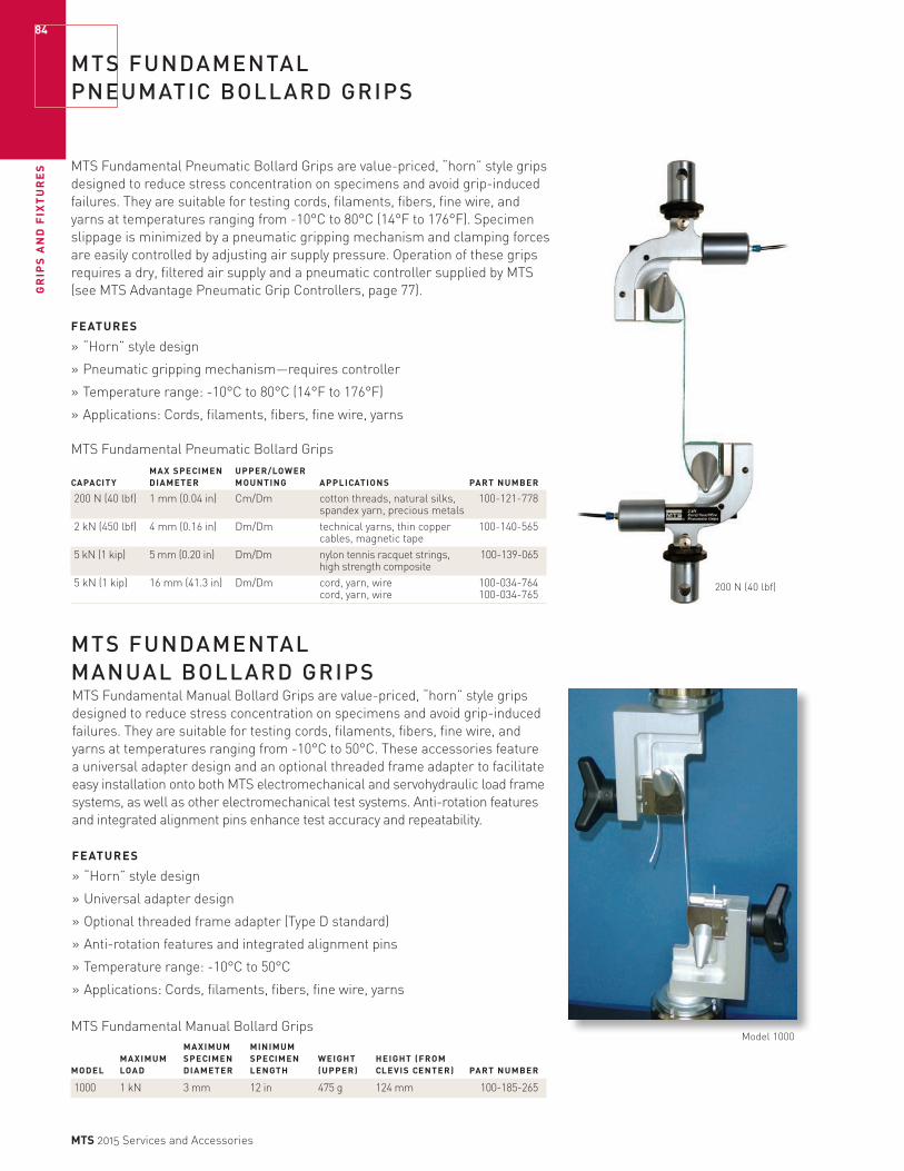
GR
IPS
AN
D F
IXT
UR
ES
84
MTS 2015 Services and Accessories
MTS FUNDAMENTAL PNEUMATIC BOLLARD GRIPS
MTS Fundamental Pneumatic Bollard Grips are value-priced, “horn” style grips designed to reduce stress concentration on specimens and avoid grip-induced failures. They are suitable for testing cords, filaments, fibers, fine wire, and yarns at temperatures ranging from -10°C to 80°C (14°F to 176°F). Specimen slippage is minimized by a pneumatic gripping mechanism and clamping forces are easily controlled by adjusting air supply pressure. Operation of these grips requires a dry, filtered air supply and a pneumatic controller supplied by MTS (see MTS Advantage Pneumatic Grip Controllers, page 77).
FEATURES
» “Horn” style design
» Pneumatic gripping mechanism—requires controller
» Temperature range: -10°C to 80°C (14°F to 176°F)
» Applications: Cords, filaments, fibers, fine wire, yarns
MTS Fundamental Pneumatic Bollard Grips MAX SPECIMEN UPPER/LOWER CAPACITY DIAMETER MOUNTING APPLICATIONS PART NUMBER
200 N (40 lbf) 1 mm (0.04 in) Cm/Dm cotton threads, natural silks, 100-121-778 spandex yarn, precious metals2 kN (450 lbf) 4 mm (0.16 in) Dm/Dm technical yarns, thin copper 100-140-565 cables, magnetic tape5 kN (1 kip) 5 mm (0.20 in) Dm/Dm nylon tennis racquet strings, 100-139-065 high strength composite5 kN (1 kip) 16 mm (41.3 in) Dm/Dm cord, yarn, wire 100-034-764 cord, yarn, wire 100-034-765
MTS FUNDAMENTAL MANUAL BOLLARD GRIPSMTS Fundamental Manual Bollard Grips are value-priced, “horn” style grips designed to reduce stress concentration on specimens and avoid grip-induced failures. They are suitable for testing cords, filaments, fibers, fine wire, and yarns at temperatures ranging from -10°C to 50°C. These accessories feature a universal adapter design and an optional threaded frame adapter to facilitate easy installation onto both MTS electromechanical and servohydraulic load frame systems, as well as other electromechanical test systems. Anti-rotation features and integrated alignment pins enhance test accuracy and repeatability.
FEATURES
» “Horn” style design
» Universal adapter design
» Optional threaded frame adapter (Type D standard)
» Anti-rotation features and integrated alignment pins
» Temperature range: -10°C to 50°C
» Applications: Cords, filaments, fibers, fine wire, yarns
MTS Fundamental Manual Bollard Grips MAXIMUM MINIMUM MAXIMUM SPECIMEN SPECIMEN WEIGHT HEIGHT (FROM MODEL LOAD DIAMETER LENGTH (UPPER) CLEVIS CENTER) PART NUMBER
1000 1 kN 3 mm 12 in 475 g 124 mm 100-185-265
Model 1000
200 N (40 lbf)

GR
IPS
AN
D F
IXT
UR
ES
85
MTS 2015 Services and Accessories
MTS FUNDAMENTAL COEFFICIENT OF FRICTION GRIPS
MTS Fundamental Coefficient of Friction Grips employ a pulley and string mechanism to measure the force required to pull a friction sled over a material specimen. They are suitable for meeting a variety of material testing standards, including ASTM D1894 (plastic film), TAPPI T542 (paper and cardboard), TAPPI T549 (non-fibrous materials), and TAPPI T816 (corrugated). The upper grip is not included.
FEATURES
» Pulley and string mechanism
» Applications: Plastic film, paper and cardboard, non-fibrous materials, corrugated
FIXTURE PART NUMBER
Coefficient of Friction 100-087-526
MTS FUNDAMENTAL 90° PEEL FIXTURE
MTS Fundamental 90° Peel Fixtures employ precision bearings to maintain perpendicular axial alignment while measuring the force required to peel adhered material from a clamped-down substrate. They are suitable for meeting a variety of material testing standards, including ASTM D1876, FINAT FTM1/2/3, and AFERA 4015 T4. The upper grip is not included.
FEATURES
» Precision bearings
» Applications: ASTM D1876, FINAT FTM1/2/3, and AFERA 4015 T4
FIXTURE PART NUMBER
90° Peel 100-170-762

GR
IPS
AN
D F
IXT
UR
ES
86
MTS 2015 Services and Accessories
BIONIX VISE ACTION GRIPS
Bionix Vise Action Grips are value-priced, miniature, medium, and heavy-duty general purpose tensile grips that use a clamping screw to tighten a vise; each order includes a set of rubber faces. Available in a variety of load capacities and sizes, they are suitable for testing bandages, bio-textiles, diapers, and plastic films at temperatures ranging from -10°C to 50°C. Comprised of durable stainless steel, they can be safely deployed within a saline environmental bath. These accessories feature a universal adapter design and an optional threaded frame adapter to facilitate easy installation onto both MTS electromechanical and servohydraulic load frame systems, as well as other electromechanical test systems. Anti-rotation features and integrated alignment pins enhance test accuracy and repeatability.
FEATURES
» Stainless steel—suitable for saline environmental bath
» Set of rubber faces standard with each order
» Universal adapter design (Type D standard)
» Optional threaded frame adapter
» Anti-rotation features and integrated alignment pins
» Temperature range: -10°C to 50°C
» Applications: Bandages, bio-textiles, diapers, plastic films
MTS Bionix Vise Action Grips MAXIMUM MAXIMUM MAXIMUM SPECIMEN SPECIMEN WEIGHT HEIGHT (FROM MODEL LOAD FACE PROFILE THICKNESS WIDTH (UPPER) CLEVIS CENTER) PART NUMBER
100 100 N Rubber 2 mm 10 mm 560 g 100 mm 100-186-411
2000 2 kN Rubber 3.5 mm 63 mm 1000 g 95 mm 100-174-783
5000 5 kN Rubber 10 mm 80 mm 3100 g 140 mm 100-186-413
Model 2000/5000
Model 100
GR
IPS
AN
D F
IXT
UR
ES
87
MTS 2015 Services and Accessories
Model 2000
BIONIX SCISSORS ACTION GRIPS
Bionix Scissors Action Grips are value-priced, self-tightening, and self-aligning grips featuring diamond faces. They are suitable for testing irregular bio-materials, bone, cartilage, tendons, and replacement bio-medical components at temperatures ranging from -130°C to 250°C. Comprised of durable stainless steel, they can be safely deployed within a saline environmental bath. These accessories feature a universal adapter design and an optional threaded frame adapter to facilitate easy installation onto both MTS electromechanical and servohydraulic load frame systems, as well as other electromechanical test systems. Anti-rotation features and integrated alignment pins enhance test accuracy and repeatability.
Bionix Scissors Action Grips MAXIMUM MAXIMUM MAXIMUM SPECIMEN SPECIMEN WEIGHT HEIGHT (EACH MODEL LOAD THICKNESS WIDTH (UPPER) CLEVIS CENTER) PART NUMBER
2000 1 kN 10 mm 25 mm 850 g 160 mm 100-181-625
FEATURES
» Stainless steel—suitable for saline environmental bath
» Self-tightening and self-aligning
» Diamond grip faces
» Universal adapter design (Type D standard)
» Optional threaded frame adapter
» Anti-rotation features and integrated alignment pins
» Temperature range: -130°C to 250°C
» Applications: Irregular bio-material, bone, cartilage, tendons, replacement bio-medical components

GR
IPS
AN
D F
IXT
UR
ES
88
MTS 2015 Services and Accessories
BIONIX STAINLESS STEEL COMPRESSION PLATENS
Bionix Stainless Steel Compression Platens are value-priced, compression platens with precision-ground, hardened surfaces. Available in a variety of sizes, they are suitable for testing bio-materials, bone, cartilage, tendons, and replacement bio-medical components at temperatures ranging from -130°C to 250°C. Comprised of durable stainless steel, they can be safely deployed within a saline environmental bath. These accessories feature a universal adapter design and an optional threaded frame adapter to facilitate easy installation onto both MTS electromechanical and servohydraulic load frame systems, as well as other electromechanical test systems. Specimen centering grooves, anti-rotation features, and integrated alignment pins enhance test accuracy and repeatability.
Bionix Stainless Steel Compression Platens MAXIMUM MAXIMUM SPECIMEN WEIGHT HEIGHT (FROM MODEL LOAD DIAMETER (UPPER) CLEVIS CENTER) PART NUMBER
50 10 kN 50 mm 681 g 64 mm 100-182-229
100 10 kN 100 mm 1820 g 64 mm 100-182-227
150 10 kN 150 mm 3725 g 64 mm 100-182-226
FEATURES
» Stainless steel—suitable for saline environmental bath
» Precision-ground, hardened surface
» Universal adapter design (Type D standard)
» Optional threaded frame adapter
» Specimen centering grooves
» Anti-rotation features and integrated alignment pins
» Temperature range: -130°C to 250°C
» Applications: Irregular bio-material, bone, cartilage, tendons, replacement bio-medical components
Model 50

GR
IPS
AN
D F
IXT
UR
ES
89
MTS 2015 Services and Accessories
BIONIX ROLLER ACTION GRIPS
Versatile Bionix Roller Action Grips are value-priced, quick-loading, and self-tightening roller grips suitable for testing bandages, bio-textiles, diapers, synthetics, and flexible polymers at temperatures ranging from -10°C to 50°C for the 1 kN grips and from -130°C to 250°C for the 2kN and 5 kN grips. Available in a variety of load capacities and sizes, these accessories feature a universal adapter design and an optional threaded frame adapter to facilitate easy installation onto both MTS electromechanical and servohydraulic load frame systems, as well as other electromechanical test systems. Anti-rotation features and integrated alignment pins enhance test accuracy and repeatability.
FEATURES
» Quick-loading, self-tightening
» Universal adapter design (Type D standard)
» Optional threaded frame adapter
» Anti-rotation features and integrated alignment pins
» Temperature range: -10°C to 50°C for 1 kN; -130°C to 250°C for 2 kN and 5 kN
» Applications: Bandages, bio-textiles, diapers, synthetics, flexible polymers
Model 1000
Model 2000/5000
Bionix Roller Action Grips
MAXIMUM MAXIMUM MAXIMUM SPECIMEN SPECIMEN WEIGHT HEIGHT (FROM TEMPERATURE MODEL LOAD THICKNESS WIDTH (UPPER) CLEVIS CENTER) RANGE PART NUMBER
1000 1 kN 3 mm 50 mm 1300 g 123 mm -10°C to 50°C 100-185-262
2000 2 kN 4 mm 50 mm 1425 g 111 mm -130°C to 250°C 100-184-839
5000 5 kN 7 mm 75 mm 2260 g 121 mm -130°C to 250°C 100-184-841
GR
IPS
AN
D F
IXT
UR
ES
90
MTS 2015 Services and Accessories
BIONIX MANUAL BOLLARD STYLE GRIPS
Bionix Manual Bollard Grips are value-priced, “horn” style grips designed to reduce stress concentration on specimens and avoid grip-induced failures. They are suitable for testing cords, filaments, fibers, fine wire, and yarns at temperatures ranging from -130°C to 250°C. These accessories feature a universal adapter design and an optional threaded frame adapter to facilitate easy installation onto both MTS electromechanical and servohydraulic load frame systems, as well as other electromechanical test systems. Anti-rotation features and integrated alignment pins enhance test accuracy and repeatability.
FEATURES
» “Horn” style design
» Universal adapter design (Type D standard)
» Optional threaded frame adapter
» Anti-rotation features and integrated alignment pins
» Temperature range: -130°C to 250°C
» Applications: Cords, filaments, fibers, fine wire, yarns
Bionix Manual Bollard Style Grips MAXIMUM MAXIMUM SPECIMEN WEIGHT HEIGHT (EACH MODEL LOAD DIAMETER (UPPER) FROM CLEVIS CENTER) PART NUMBER
1000 1 kN 3 mm 1010 g 124 mm 100-185-264
Model 1000

GR
IPS
AN
D F
IXT
UR
ES
91
MTS 2015 Services and Accessories
Model 10A, fully open
Model 10A, jaws parallel
Model 10B, (with rubber face),fully open
Model 10B,(with rubber face),jaws parallel
Model 10B, fully open,(with no rubber face material)
Model 10B,(with no rubber face material), jaws parallel
B
D
D
D B
C
C
C
B
BIONIX SPRING ACTION GRIPS
Bionix Spring Action Grips are a reliable and economical choice for low-force biomedical testing applications. Available with a variety of mounting threads and jaw surfaces, these lightweight grips are suitable for testing films, papers, and textiles at temperatures ranging from -75°C to 200°C (-103°F to 400°F). Comprised of durable stainless steel, they can be safely deployed within a saline environmental bath. All Bionix Spring Action Grip sets include two grip assemblies, two spare springs, two spare wires for link pin retainers, rubber jaw pad material, and a shipping case.
FEATURES
» Stainless steel—suitable for saline environmental bath
» Available with a variety of mounting threads and jaw surfaces
» Spring action follow-through accommodates specimen neckdown
» Faces pivot for self alignment and reduced likelihood of breakage at the specimen/face contact
» Temperature range: -75°C to 200°C (-103°F to 400°F)
» Applications: Films, papers, textiles
» Force of jaw tips (jaws parallel): 32 N ± 4.4 N (7.2 lbf ± 1.1 lbf)
Bionix Spring Action Grips
MODEL MOUNTING THREAD SPAN “B” SPAN “C” SPAN “D” JAW SURFACE PART NUMBER
10A M6 x 1 mm 0.0 1.0 mm (0.039 in) 2.6 mm (0.103 in) Flat Smooth 056-077-501
10A 1/4 in -28UNF 0.0 1.0 mm (0.039 in) 2.6 mm (0.103 in) Flat Smooth 056-077-502
10B M6 x 1 mm 0.0 1.0 mm (0.039 in) 2.6 mm (0.103 in) Rubber Face 056-077-503
10B 1/4 in -28UNF 0.0 1.0 mm (0.039 in) 2.6 mm (0.103 in) Rubber Face 056-077-504
10B M6 x 1 mm 1.6 mm (0.064 in) 2.6 mm (0.103 in) 4.2 mm (0.167 in) Flat Smooth 056-077-503
10B 1/4 in -28UNF 1.6 mm (0.064 in) 2.6 mm (0.103 in) 4.2 mm (0.167 in) Flat Smooth 056-077-504
GR
IPS
AN
D F
IXT
UR
ES
92
MTS 2015 Services and Accessories
BIONIX ENVIROBATH
The value-priced and versatile Bionix EnviroBath facilitates accurate and efficient mechanical testing of medical device and biomaterial specimens in fluids heated to body temperatures. Engineered for biomedical and general material test applications, the Bionix EnviroBath is easy to set up, operate, and maintain and is available in a range of volume configurations to accommodate a broad variety of test specimens. A universal adapter design ensures full compatibility with all MTS electromechanical, electrodynamic and servohydraulic load frame systems, as well as other electromechanical test systems.
» Variety of volume configurations: 1 l, 6 l, 10 l
» Supports saline and protein-based fluids
» Utilizes a wide selection of Bionix grips and fixtures
» Reliable fluid temperature control mechanism
» Compatible with video or laser extensometer
» Optional protein-based fluid system
Bionix EnviroBath TORSIONAL INTERNAL DIMENSIONS EXTERNAL DIMENSIONS VOLUME AXIAL FORCE FORCE WXHXD WXHXD
1 1 l 2.4 kN 28 N.m 100 x 200 x 56 mm 180 x 295 x 95 mm 4 x 8 x 2.2 in 7 x 11.5 x 3.65 in
6 6 l 2.4 kN 28 N.m 130 x 480 x 100 mm 205 x 575 x 140 mm 5 x 19 x 3.9 in 8 x 22.5 x 5.5 in
10 10 l 10 kN 100 N.m 215 x 305 x 150 mm 295 x 395 x 190 mm 8.5 x 12 x 5.8 in 11.5 x 15.5 x 7.4 in
General Specifications TEMPERATURE
Range: 5˚C above ambient to 40˚C
Stability: ±2˚C at 37˚C
POWER (V AC, HZ, A)
US: 120 V AC, 50/60 Hz, 11 A
Europe: 240 V AC, 50 Hz, 10 A
Easy to disassemble to clean.
GR
IPS
AN
D F
IXT
UR
ES
93
MTS 2015 Services and Accessories
BIONIX ENVIROBATH
Options
1 l i ter 6 l i ter 10 l i ter
Mist/Spray Option √ √Protein Based Fluid √ √ √Horizontal √ √
Digital Temperature Monitor √ √ √Upper Pull Rod (SST) √ √ √
Compatibility Matrix* GRIPS AND FIXTURES 1 l i ter 6 l i ter 10 l i ter PART NUMBER
Bionix Vise Action Grips, 100 N √ √ √ 100-186-411
Model 642.001 Bend Fixture (SST) √ √ √ 100-201-456 (S/H & E/D)
Bionix Manual Thumb Screw Grip, 100 N √ √ √ 100-167-987
Bionix Compression Platens, 40 mm √ √ √ 100-203-455
Bionix Spring Action Grips √ √ 056-077-50x
Bionix Compression Platens, 50 mm √ √ 100-182-229
Bionix Vise Action Grips, 2 kN √ √ 100-174-783
Bionix Roller Action Grips, 1 kN √ √ 100-185-262
Model 642.01 Bend Fixture (SST) √ 100-203-453 (S/H & E/D)
Bionix Compression Platens, 100 mm √ 100-182-227
Model 686.01A-31 Axial Torsional Grips (SST) √ 051-882-201
Note: EnviroBath 10 is compatible with customer-supplied spinal fixture per ASTM F1717-01.
Some grips available in titanium. Contact MTS for additional information.* Vertical Orientation
Electromechanical Load Frames 1 l i ter 6 l i ter 10 l i ter
MTS Single Column Standard Length √ √MTS Single Column Extended Length √ √ √MTS Dual Column Standard and Extended Length √ √ √Legacy MTS load frames and Instron E/M load frames Consult MTS
Electrodynamic Load Frames 1 l i ter 6 l i ter 10 l i ter
MTS Acumen 1 √ √MTS Acumen 3 √ √
Servohydraulic Load Frames 1 l i ter 6 l i ter 10 l i ter
Bionix Tabletop Axial or Axial/Torsional √1 √1, 2 √MTS Landmark3 √ √ √Legacy MTS load frames3 Consult MTS
1 Additional adapter required.2 Extended columns required. 3 Cross-head mounted actuator.

GR
IPS
AN
D F
IXT
UR
ES
94
MTS 2015 Services and Accessories
MTS EM EXTEND KITS
MTS load frame extension rod kits enhance your testing capabilities within environmental chambers. The rods are designed to apply tension and compression in an environmental chamber from temperatures of -130°C (-200°F) to 315°C (600°F). The Type C and Type D kits consist of five different extension lengths. These five different lengths can be configured into 23 different combination lengths. This configurability allows users to test low and high profile accessories or short and tall specimens. Compression platens are usually low profile and will need more extension lengths. Pneumatic grips take up more space and will require fewer lengths.
A load frame rod extension kit maximizes the internal test space of the environmental chamber for grips and fixtures. The upper extension rod can be adjusted in 25 mm increments. By combining the five different lengths, 23 combination heights are ultimately available providing pin-to-pin dimensions ranging from 100 mm (3.9 in) to 825 mm (32.4 in).
The Type D extension kit is compatible with MTS and Instron® clevis pin couplings. It is designed for tension or compression loads from 2 kN to 150 kN. All extension lengths are stainless steel and have ports for water cooling.
FEATURES
» Water-cooling ports
» Lightweight design minimizes tare weight
» Tight tolerances ensure angular and concentric alignment are retained
» Rated for tension and compression
» Stainless steel construction minimizes heat transfer
» Preloaded joints
BENEFITS
» Highly configurable to test various size specimens
» Reduces test setup time
Type “C” Type “D”
Load extension kits are packaged in a protective case. From left to right, the lengths are denoted as L1 through L5.
MTS EM Extend KitMODEL TYPE C TYPE D
Part Number 100-151-425 100-150-815
Force Rating 200 N (40 lb) 150 kN (33,000 lb)
Temperature Rating -130°C to 315°C (-200°F to 600°F) -130°C to 315°C (-200°F to 600°F)
Length 1 (L1)* 100 mm (3.9 in) 100 mm (3.9 in)
Length 2 (L2)* 125 mm (4.9 in) 125 mm (4.9 in)
Length 3 (L3)* 150 mm (5.9 in) 150 mm (5.9 in)
Length 4 (L4)* 200 mm (7.8 in) 200 mm (7.8 in)
Length 5 (L5)* 250 mm (9.8 in) 250 mm (9.8 in)
Weight 1 0.18 kg (0.40 lb) 0.93 kg (2.06 lb)
Weight 2 0.20 kg (0.45 lb) 1.1 kg (2.47 lb)
Weight 3 0.23 kg (0.50 lb) 1.25 kg (2.77 lb)
Weight 4 0.29 kg (0.65 lb) 1.57 kg (3.47 lb)
Weight 5 0.38 kg (0.85 lb) 1.93 kg (4.27 lb)
FU
RN
AC
ES
& C
HA
MB
ER
S
95
MTS 2015 Services and Accessories
RELIABLE FURNACE AND TEMPERATURE CONTROLLER COMBINE PERFORMANCE AND AFFORDABILITY
MTS Model 653 High-Temperature Furnaces are ideal for a wide variety of high-temperature tests, including tension, compression, bend and fatigue testing of metals, composites, ceramics and many other materials. The furnaces have a user-friendly design that helps operators perform setup tasks more quickly – without compromising test quality or accuracy.
Model 653 furnaces streamline test setup and specimen changeover with a clamshell design that allows operators to work from the front of the furnace at all times. This design also improves furnace alignment, which is critical to achieving proper gradients. The durable, low-maintenance insulation for Model 653.03 and 653.04 furnaces comes pre-cut, so there is no need to handle the material in the lab. It fits tighter around the pushrods, reducing heat loss and eliminating the need for wool. The flow switches of the grip water cooling circuit can be integrated with the Model 409 temperature controller, shutting down the furnace to protect the equipment and specimen in the event of a water supply failure.
Furnaces TEMPERATURE OVERALL HOT ZONE HOT ZONE NUMBER MODEL MAX/MIN* HEIGHT HEIGHT WIDTH & DEPTH OF ZONES
653.01 1400°C/100°C 55 mm 19 mm 50 x 50 mm 1
653.02 1400°C/100°C 85 mm 50 mm 50 x 50 mm 2
653.03 1400°C/100°C 126 mm 90 mm 62.5 x 62.5 mm 2
653.04** 1400°C/100°C 220 mm 185 mm 62.5 x 62.5 mm 3
* Nominal temperatures may vary depending on specimen geometry and material. 1400°C is achieved in a non-testing environment.** Supports testing to ASTM E606-04e1. BSI 7270, JIS Z2279, AFNOR A03-403 or ISO 12106 requirements.Note: When ordering, please indicate voltage requirements and provide necessary load frame dimensions in order to determine system integration requirements.
MODEL 653.XX FURNACE FEATURES:
» Capable of achieving temperatures up to 1400 C (2550 F) (non-testing environment)
» Capable of achieving 1000 C (1800 F) in validated testing conditions with standard solution
» Single or multiple zone heating
» Clamshell design streamlines test setup, furnace alignment, and specimen changeover
» Silicon carbide heating elements and alumina fiber insulation system for low heat loss and long life
» Multiple furnace heights to accommodate diverse test requirements
» Mounting bracket for a variety of MTS load frames is included
» Designed to accommodate MTS high-temperature axial extensometers
THERMAL GRADIENT VERIFICATION KIT COMPONENTS (OPTIONAL) PART NUMBER
Thermocouple Data Acquisition Kit 100-255-716
Type K Thermocouple Connector Kit 100-255-714
Thermocouple Specimen 057-743-803
Thermocouple Welding Kit 100-256-698
MODEL 409.83 TEMPERATURE CONTROLLER FEATURES:
» Multiple mounting options – on included furnace mounting bracket or optional stand for floor or table
» Compact, ergonomic design
» Multiple level, self-tuning PID control
» SCR power relays included
» Digital communications available

FU
RN
AC
ES
& C
HA
MB
ER
S96
MTS 2015 Services and Accessories
THERMOMECHANICAL FATIGUE (TMF) SUBSYSTEM WITH INDUCTION HEATING
The MTS TMF Subsystem is ideal for inducing thermal cycling in a metallic (magnetically susceptible) specimen. A combination of induction heating and air cooling allows thermomechanical fatigue tests to be performed in or out of phase with a load force. The TMF subsystem has a user-friendly design that helps operators perform repeatable test setup tasks quickly. Air cooling jets and the induction coil have easy, repeatable adjustments, meaning that specimen changes do not require as much setup time to reestablish the initial conditions. A specimen centering tool provides quick initial position for the coil. The coil is mounted on an x, y, z positioner that has manual adjustment knobs with numerical indicators allowing 50 mm of travel in 3-axes for fine positioning relative to the specimen. A quick release slide allows the coil to be easily pulled from the test space with the ability to return to its original position. Air cooling jets are also easily folded back or removed to gain access to the specimen with the same ability to snap back into the original position.
The induction coil is coated in electrically insulating material to provide an additional safety factor against electric shock. The coil, generator and RF oscillator are water cooled and interlocked for water flow. A second interlock specimen thermocouple also provides indication in the event that the primary control thermocouple becomes detached. TestSuite software templates for TMF include test setup, to establish thermal gradients, and test run to perform and report results on the TMF test.
TMF SUBSYSTEM FEATURES:
» 10 kW RF Generator with temperature controller and secondary temperature interlock controller
» Air-cooling jets with detachable arms and adjustable flow profiles
» 10°C/second heating and cooling with higher open loop heating rates possible
» Up to 1200°C
» X,Y,Z coil with position indication and quick release slide-back mount
» Type K or Type R thermocouple compatibility
» Water chiller for RF generator and coil
» Tool kit for coil centering and adjustment
» Standard 5-turn electrically insulated induction coil
» TestSuite Templates for setup and test control
» Instrumented specimen for equipment checkout and validation
» 16 channel thermocouple data acquisition module
» Thermocouple connector kit to interface with specimen
» Designed to accommodate MTS high-temperature axial extensometers
When ordering, please indicate power choice of water chiller(50 Hz or 60 Hz),
thermocouple type (R or K).

FU
RN
AC
ES
& C
HA
MB
ER
S
97
MTS 2015 Services and Accessories
ENVIRONMENTAL CHAMBER WITH BUILT-IN CONTROLLER
These Chambers Help You Accomplish Material and Component Testing Faster, with More Accurate ResultsThese chambers have open-coil heating which means your test specimen and grips are heated to the desired temperature very quickly.
MODEL 651 CHAMBER FEATURES INCLUDE:
» High-flow capacity fan reduces thermal gradients in the air and test specimen for more accurate results.
» Hinged, lift-off doors open to 180° for easy access to chamber’s interior.
» Extra small ports allow extensometer cables to pass through so they won’t be crushed in the door.
» Liquid nitrogen solenoid is included.
ENVIRONMENTAL CHAMBER CART (FOR MODEL 651.06
AND 651.10 ENVIRONMENTAL CHAMBERS)If you want the convenience of mobility, this heavy duty, adjustable cart will be of interest. Its sturdy construction, locking wheels, floor levelers, and screw-driven lifting mechanism provides a safe, reliable, and versatile means of using your environmental chamber with different testing systems. This cart supports the chamber independent of the load frame. The height is adjustable.
MODELS 651.06E-03, 651.06E-04 AND 651.10E-04
CHAMBERS ALSO INCLUDE:
» Removable port plugs allow easy installation without disassembling the load train.
» Interior light.
» Eurotherm® 2404 controller with RS-485.
TEMPERATURE CONTROLLER MOUNTED ON BACKThe temperature controller is mounted to the back of the chamber. This controller features closed-loop PID control of heating and cooling. Its front panel displays set point and current temperature. It also has an autotuning mode.
For chamber specifications, see next page.
Specifications CLEARANCE INSIDE LEG OUTSIDE MODEL HEIGHT FOOTPRINT DIMENSIONS PART NUMBER
651.20B-01 931 mm to 1293 mm 1270 mm 1430 mm x 1118 mm 100-160-646
(36.65 in to 50.9 in) (50 in) (56.3 in x 44.0 in)
651.20B-02* 931 mm to 1293 mm 1410 mm 1570 mm x 1118 mm 100-213-156
(36.65 in to 50.9 in) (55.5 in) (61.8 in x 44.0 in)
* 370.50 load frame
FU
RN
AC
ES
& C
HA
MB
ER
S98
MTS 2015 Services and Accessories
This Model Ideal for Tabletop Load FramesModel 651.05E Environmental Chamber has all the features of other Model 651 Chambers, and includes adjustable legs for use in tabletop load frames.
For Acumen chamber applications, please contact an MTS Application Engineer. New options available in FY14.
General Specifications Model 651.xx
Voltage 208/230 V
Line Frequency 50/60 Hz
Phase 1 phase
Specifications RECOVERY TIME TO SET POINT TEMPERATURE RANGE AIR TEMPERATURE PERFORMANCE TEMPERATURE DOOR OPEN: MODEL MIN/MAX POWER FAN POWER HEATING COOLING 1 MIN 2 MIN
651.05E-02 -75°C to 315°C 2 kW 1/4 hp Ambient to 525°F Ambient to -100°F 5 min 6 min (-100°F/600°F) in less than 45 min in less than 20 min
651.06E-03 -129°C to 315°C 4 kW 1/4 hp Ambient to 600°F Ambient to -200°F 5 min 6 min (-200°F/600°F) in less than 30 min in less than 20 min
651.06E-04 -129°C to 315°C 8 kW 1/4 hp Ambient to 600°F Ambient to -200°F 4 min 5 min (-200°F/600°F) in less than 30 min in less than 20 min
651.10E-04 -129°C to 540°C 8.5 kW 1/4 hp Ambient to 1000°F Ambient to -200°F 8 min 10 min (-200°F/1000°F) in less than 70 min in less than 20 min
Dimensions
INTERIOR SPACE EXTERNAL DIMENSIONS* MODEL WIDTH DEPTH HEIGHT WIDTH DEPTH HEIGHT
651.05E-02 285 mm (11.25 in) 305 mm (12.0 in) 457 mm (18.0 in) 413 mm (16.25 in) 914 mm (36.0 in) 584 mm (23.0 in)
651.06E-03 356 mm (14.0 in) 432 mm (17.0 in) 559 mm (22.0 in) 508 mm (20.0 in) 787 mm (31.0 in) 711 mm (28.0 in)
651.06E-04 356 mm (14.0 in) 432 mm (17.0 in) 813 mm (32.0 in) 508 mm (20.0 in) 787 mm (31.0 in) 965 mm (38.0 in)
651.10E-04 356 mm (14.0 in) 432 mm (17.0 in) 660 mm (26.0 in) 508 mm (20.0 in) 787 mm (31.0 in) 813 mm (32.0 in)
* Chamber only. Does not include control box.
MODEL PART NUMBER*
651.05E-02 (US Plug) 056-807-906
651.05E-02 (WW Plug) 056-808-006
651.06E-03 056-097-207
651.06E-04 056-097-008
651.10E-04 056-097-106
* Compatible with FlexTest 40 & 60. For other controller interfaces, please contact MTS.
ENVIRONMENTAL CHAMBER WITH BUILT-IN CONTROLLER

TE
ST
SY
ST
EM
CO
MP
ON
EN
TS
99
MTS 2015 Services and Accessories
SERIES 244 HYDRAULIC ACTUATORS
Servoactuators play a critical role in achieving accuracy and repeatable test results. MTS engineers use proprietary materials and processes to minimize friction, while maximizing reliability, wear resistance, and ease of maintenance. Every day, thousands of engineers use MTS actuators in demanding dynamics, structural fatigue, and component test applications.
Series 244 Hydraulic Actuators are our most popular linear, high performance actuator for servohydraulic control applications. This actuator is fatigue rated and designed for years of trouble free operation.
TYPICAL APPLICATIONS
» Highly dynamic fatigue testing of components
» Structural fatigue tests
» Vehicle durability tests
STANDARD FEATURES
» Fatigue rated design for years of reliable service in demanding applications.
» Double ended, one piece piston-rod design combines balanced dynamic performance with higher side-loading capacity.
» Proprietary MTS polytetraflouroethylene (PTFE) high and low pressure seal designs lead the industry in durability, long life, and performance. Exceptional end caps contain low-pressure seals that prevent external contamination from entering the actuator and minimize the amount of external leakage.
» Bonded polymer bearings resist rod and bearing wear during high velocity operation.
» Internal Linear Variable Displacement Transducer provides the displacement signal for position feedback in a closed loop servocontrol application.
» Hydraulic cushions protect the end caps during full stroke, high velocity operation.
Series 244 Hydraulic Actuator Specifications ENGLISH/ FORCE RATING- STROKE FLOW MINIMUM ROD MODEL METRIC DYNAMIC LENGTH RATING WEIGHT LENGTH DIAMETER PART NUMBER
244.11 A-05 US Customary 3.3 Kip 6 in 90 gpm 49 lb 25.56 in 1.75 in 036-771-201
244.11 A-05 Metric 15 kN 150 mm 340 lpm 22.2 kg 649 mm 44.5 mm 036-771-201
244.11 A-07 US Customary 3.3 Kip 10 in 90 gpm 63 lb 33.56 in 1.75 in 036-771-202
244.11 A-07 Metric 15 kN 250 mm 340 lpm 28.6 kg 852 mm 44.5 mm 036-771-202
244.12 A-05 US Customary 5.5 Kip 6 in 90 gpm 51 lb 25.56 in 1.75 in 036-771-301
244.12 A-05 Metric 25 kN 150 mm 340 lpm 23.1 kg 649 mm 44.5 mm 036-771-301
244.12 A-07 US Customary 5.5 Kip 10 in 90 gpm 66 lb 33.56 in 1.75 in 036-771-302
244.12 A-07 Metric 25 kN 250 mm 340 lpm 30.0 kg 852 mm 44.5 mm 036-771-302
244.21 A-05 US Customary 11 Kip 6 in 90 gpm 88 lb 25.46 in 2.75 in 036-771-411
244.21 A-05 Metric 50 kN 150 mm 340 lpm 40.0 kg 647 mm 69.9 mm 036-771-411
244.21 A-07 US Customary 11 Kip 10 in 90 gpm 116 lb 33.46 in 2.75 in 036-771-412
244.21 A-07 Metric 50 kN 250 mm 340 lpm 52.6 kg 850 mm 69.9 mm 036-771-412
244.22 A-05 US Customary 22 Kip 6 in 90 gpm 142 lb 24.96 in 2.75 in 036-771-511
244.22 A-05 Metric 100 kN 150 mm 340 lpm 64.4 kg 659 mm 69.9 mm 036-771-511
244.22 A-07 US Customary 22 Kip 10 in 90 gpm 174 lb 32.96 in 2.75 in 036-771-512
244.22 A-07 Metric 100 kN 250 mm 340 lpm 78.9 kg 837 mm 69.9 mm 036-771-512
244.31 A-05 US Customary 55 Kip 6 in 90 gpm 303 lb 25.46 in 3.75 in 036-771-711
244.31 A-05 Metric 250 kN 150 mm 340 lpm 137.4 kg 649 mm 95.3 mm 036-771-711
244.31 A-07 US Customary 55 Kip 10 in 90 gpm 375 lb 33.46 in 3.75 in 036-771-712
244.31 A-07 Metric 250 kN 250 mm 340 lpm 170.1 kg 850 mm 95.3 mm 036-771-712
Double ended actuator with equal area LVDT displacement transducer -06 JIC drain connection

TE
ST
SY
ST
EM
CO
MP
ON
EN
TS
100
MTS 2015 Services and Accessories
SERIES 252 SERVOVALVES
MTS Series 252 Servovalves are two stage, four-way valves designed for servocontrol of hydraulic systems. These high performance servovalves are available in a range of flow rates from 4 to 227 lpm (1 to 60 gpm).
Model 252.2x Servovalve
Series 252 Servovalve Specifications
FLOW PILOT 90° POINT @ MODEL RATING PRESSURE 10% COMMAND PART NUMBER
252.21G-01 4 lpm (1 gpm) No 240 Hz 056-006-101
252.21G-04 4 lpm (1 gpm) Yes 240 Hz 056-006-104
252.22G-01 9.5 lpm (2.5 gpm) No 240 Hz 056-006-201
252.22G-04 9.5 lpm (2.5 gpm) Yes 240 Hz 056-006-204
252.23G-01 19 lpm (5 gpm) No 240 Hz 056-006-301
252.23G-04 19 lpm (5 gpm) Yes 240 Hz 056-006-304
252.24G-01 37 lpm (10 gpm) No 200 Hz 056-006-401
252.24G-04 37 lpm (10 gpm) Yes 200 Hz 056-006-404
252.25G-01 56 lpm (15 gpm) No 170 Hz 056-006-501
252.25G-04 56 lpm (15 gpm) Yes 170 Hz 056-006-504
252.26G-01 63 lpm (16.5 gpm) No 120 Hz 056-061-301
252.26G-04 63 lpm (16.5 gpm) Yes 120 Hz 056-061-304
252.31A-01 93 lpm (25 gpm) Convertible 80 Hz 004-823-101
252.32A-01 151 lpm (40 gpm) Convertible 60 Hz 004-823-201
252.33A-01 227 lpm (60 gpm) Convertible 50 Hz 004-823-301
Weight: 1 kg (2.3 lb)Electrical Interface: MS3106F14S-2SHydraulic Interface: ISO 10372-04-04-0-92Maximum Operating Pressure: 31 MPa (4500 psi)
TYPICAL APPLICATIONS
» Position, load, or velocity control of a hydraulic actuator in highly dynamic applications.
» Pressure control in a dynamic pressurization system.
STANDARD FEATURES & BENEFITS
» Rugged design for long operating life in dynamic applications.
» High resolution and low hysteresis for precise flow control.
» 31 MPa (4500 psi) operating pressure for Models 252.2x and 252.4x, 21 MPa (3000 psi) for Model 252.3x.
» Internal filtration to protect nozzle orifices from contamination.
» High spool driving forces reduce the likelihood of a sticking spool due to dirty fluid.
» Standard mounting configuration for Model 252.2x allows interchangeability between valves of different flow ratings.
SERIES 252 SERVOVALVE OPTIONSExternal Pilot Pressure—Series 252 Servovalves are available with a fifth port for external pilot pressure. External pilot pressure allows the second stage spool position circuit to be pressurized and controlled without applying system pressure to the actuator. This option is recommended when precise control of the servoactuator must be maintained when system pressure is first started.

TE
ST
SY
ST
EM
CO
MP
ON
EN
TS
101
MTS 2015 Services and Accessories
SERIES 249 SWIVEL BASE AND ROD END
Series 249 Swivels are important load transferring components. Benefits these swivels provide include: minimizing backlash, forgiving offset loads, and providing a pivot to enable planned movements.
TYPICAL APPLICATIONS
Static and dynamic structural or component test systems requiring a backlash-free actuator connection that pivots.
FEATURES
» Strong, durable, versatile swivels specifically designed for the rigorous demands of closed-loop servohydraulic testing applications.
» Force ratings available from 25 kN (5,500 lb) to 1550 kN (350,000 lb).
» Unique positive bearing preload adjustment eliminates backlash that causes load spikes and disturbs loading rates.
» Design utilizes cast, fatigue resistant, ductile iron for minimum weight and maximum strength.
» Maintenance free, non-metallic swivel bearings reduce swivel friction, eliminate the need for lubrication, and increase swivel life.
Swivel Base Specifications MOUNTING BOLT SIZE
MODEL FORCE RATING WEIGHT HEIGHT ACTUATOR END SI Metric US Customary PART NUMBER
249B.M25 25 kN (5.5 kip) 7 kg (15 lb) 127 mm (5 in) Base M10x1.50 (3/8 in-16) 100-221-936
249B.M70 70 kN (15 kip) 29 kg (64 lb) 180.0 mm (7.12 in) Base M16x2.00 (5/8 in-11) 100-221-932
249B.M160 160 kN (35 kip) 96 kg (211 lb) 238.3 mm (9.38 in) Base M16x2.00 (5/8 in-11) 100-221-924
249B.M340 340 kN (77 kip) 222 kg (488 lb) 317.5 mm (12.5 in) Base M24x3.50 (1 in-8) 100-221-928
249B.M500 500 kN (110 kip) 334 kg (735 lb) 406.4 mm (16 in) Base M30x3.50 (1-1/4 in-7) 100-227-944
249B.M500 730 kN (165 kip) 632 kg (1390 lb) 511.3 mm (20.02 in) Base M30x3.50 (1-1/4 in-7) 100-227-948
249B.M1000 1000 kN (220 kip) 995 kg (2189 lb) 546.1 mm (21.5 in) Base M40x4.00 (1-1/2 in-6) 100-227-952
249B.M1550 1550 kN (350 kip) 2546 kg (5601 lb) 731.2 mm (28.63 in) Base M40x4.00 (1-1/2 in-6) 100-227-956
249NB.M25 25 kN (5.5 kip) 7 kg (15 lb) 127 mm (5 in) Non- Adj Base M10x1.50 (3/8 in-16) 100-221-937
249NB.M70 70 kN (15 kip) 29 kg (64 lb) 180.0 mm (7.12 in) Non- Adj Base M16x2.00 (5/8 in-11) 100-221-933
249NB.M160 160 kN (35 kip) 68 kg (150 lb) 238.3 mm (9.38 in) Non- Adj Base M16x2.00 (5/8 in-11) 100-221-925
249NB.M340 340 kN (77 kip) 163 kg (359 lb) 317.5 mm (12.5 in) Non- Adj Base M24x3.50 (1 in-8) 100-221-929
249NB.M500 500 kN (110 kip) 349 kg (768 lb) 406.4 mm (16 in) Non- Adj Base M30x3.50 (1-1/4 in-7) 100-227-945
249NB.M500 730 kN (165 kip) 602 kg (1324 lb) 511.3 mm (20.02 in) Non- Adj Base M30x3.50 (1-1/4 in-7) 100-227-949
249NB.M1000 1000 kN (220 kip) 973 kg (2141 lb) 546.1 mm (21.5 in) Non- Adj Base M40x4.00 (1-1/2 in-6) 100-227-953
249NB.M1550 1550 kN (350 kip) 2565 kg (5643 lb) 731.2 mm (28.63 in) Non- Adj Base M40x4.00 (1-1/2 in-6) 100-227-957
DESCRIPTION
Swivel Base—The swivel base can be used to attach the linear hydraulic actuator or other actuating devices to a reaction mass or frame for structural or component testing. It typically bolts to an actuator end cap, but can be used anywhere a backlash-free swivel connection is required. The mounting holes are designed to fit a variety of MTS actuators and fixtures.
249.23 base end, backlash adjustable
249.23 base end, non-backlash adjustable

TE
ST
SY
ST
EM
CO
MP
ON
EN
TS
102
MTS 2015 Services and Accessories
Swivel Rod End Specifications MOUNTING BOLT SIZE
MODEL FORCE RATING WEIGHT HEIGHT ACTUATOR END SI Metric US Customary PART NUMBER
249R.M25 25 kN (5.5 kip) 5 kg (11 lb) 120.7 mm (4.75 in) Rod M10x1.50 (3/8 in-16) 100-221-938
249R.M70 70 kN (15 kip) 24 kg (53 lb) 198.2 mm (7.8 in) Rod M16x2.00 (5/8 in-11) 100-221-934
249R.M160 160 kN (35 kip) 60 kg (132 lb) 263.7 mm (10.38 in) Rod M16x2.00 (5/8 in-11) 100-221-926
249R.M340 340 kN (77 kip) 199 kg (438 lb) 355.6 mm (14 in) Rod M24x3.50 (1 in-8) 100-221-930
249R.M500 500 kN (110 kip) 360 kg (792 lb) 406.4 mm (16 in) Rod M30x3.50 (1-1/4 in-7) 100-227-946
249R.M500 730 kN (165 kip) 706 kg (1553 lb) 546.1 mm (21.5 in) Rod M30x3.50 (1-1/4 in-7) 100-227-950
249R.M1000 1000 kN (220 kip) 1069 kg (2352 lb) 546.1 mm (21.5 in) Rod M40x4.00 (1-1/2 in-6) 100-227-954
249R.M1550 1550 kN (350 kip) 2594 kg (5707 lb) 879.6 mm (34.6 in) Rod Bolt Pattern Bolt Pattern 100-227-958
249NR.M25 25 kN (5.5 kip) 5 kg (11 lb) 120.7 mm (4.75 in) Non-Adj Rod M10x1.50 (3/8 in-16) 100-221-939
249NR.M70 70 kN (15 kip) 25 kg (55 lb) 198.2 mm (7.8 in) Non-Adj Rod M16x2.00 (5/8 in-11) 100-221-935
249NR.M160 160 kN (35 kip) 60 kg (132 lb) 263.7 mm (10.38 in) Non-Adj Rod M16x2.00 (5/8 in-11) 100-221-927
249NR.M340 340 kN (77 kip) 140 kg (308 lb) 355.6 mm (14 in) Non-Adj Rod M24x3.50 (1 in-8) 100-221-931
249NR.M500 500 kN (110 kip) 394 kg (867 lb) 406.4 mm (16 in) Non-Adj Rod M30x3.50 (1-1/4 in-7) 100-227-947
249NR.M500 730 kN (165 kip) 731 kg (1608 lb) 546.1 mm (21.5 in) Non-Adj Rod M30x3.50 (1-1/4 in-7) 100-227-951
249NR.M1000 1000 kN (220 kip) 1087 kg (2391 lb) 546.1 mm (21.5 in) Non-Adj Rod M40x4.00 (1-1/2 in-6) 100-227-955
249NR.M1550 1550 kN (350 kip) 2613 kg (5749 lb) 879.6 mm (34.6 in) Non-Adj Rod Bolt Pattern Bolt Pattern 100-227-959
DESCRIPTION
Swivel Rod End—The swivel rod end is typically attached to the other components in the force train with a US Customary or Metric thread connector stud. A fatigue-resistant, preloaded connection between the actuator and swivel can be created by using MTS Model 601 Spiral Washers in conjunction with a threaded stud.
249.23 rod end, backlash adjustable
249.23 rod end, non-backlash adjustable
SERIES 249 SWIVEL BASE AND ROD END

TE
ST
SY
ST
EM
CO
MP
ON
EN
TS
103
MTS 2015 Services and Accessories
TYPICAL ROTARY ACTUATOR CONFIGURATIONS
A functional servohydraulic rotary actuator consists of:
» Actuator with an ADT
» Servovalve
» Flange adaptor
» Actuator flexure mounting bracket
» Diaphragm flexure
» Reaction base and bracket
» Torque cell
Proper configuration of a rotary actuator takes several steps.
STEP 1—DETERMINE THE ACTUATOR MODEL FROM YOUR TORQUE REQUIREMENT
MODEL TORQUE (METRIC) TORQUE (US CUSTOMARY)
215.32 226 N.m 2,000 lbf-in
215.35 565 N.m 5,000 lbf-in
215.41 1,130 N.m 10,000 lbf-in
215.42 2,260 N.m 20,000 lbf-in
215.45 5,650 N.m 50,000 lbf-in
215.51 11,300 N.m 100,000 lbf-in
216.10 22,600 N.m 200,000 lbf-in
216.20 44,855 N.m 397,000 lbf-in
216.30 82,500 N.m 730,000 lbf-in
STEP 2—DETERMINE THE SERVOVALVE (see page 100)
MODEL SERVOVALVE QUANTITY
215.32 Model 252.2x 1
215.35 Model 252.2x 1
215.41 Model 252.2x 1 or 2
215.42 Model 252.2x 1 or 2
215.45 Model 252.2x 1 or 2
216.51 Model 252.2x 1 or 2
216.10 Model 256.0x 1
216.20 Model 256.0x 1
216.30 Model 256.0x 1
Actuator
ServovalveTorque Cell
STEP 3—DETERMINE THE TORQUE CELL
MODEL BASE PART NUMBER
215.32 663.11A-02 006-437-502
215.35 663.12A-01 006-437-504
215.41 663.12A-02 006-437-505
215.42 663.13A-02 006-437-507
215.45 663.13A-05 006-437-510
216.51 663.14A-01 006-437-511
216.10 663.15A-02 006-437-513
216.20 663.16A-01 006-437-514
216.30 663.18A-01 006-437-516

TE
ST
SY
ST
EM
CO
MP
ON
EN
TS
104
MTS 2015 Services and Accessories
STEP 4—DETERMINE THE REACTION BRACKET AND BASE
MODEL REACTION BRACKET PART NUMBER REACTION BASE PART NUMBER
215.32 215.35 TCRB 043-962-701 215.35 RB 044-527-001
215.35 215.35 TCRB 043-962-701 215.35 RB 044-527-001
215.41 215.42 TCRB 043-962-801 215.42 RB 044-702-901
215.42 215.42 TCRB 043-962-801 215.42 RB 044-702-901
215.45 215.45 TCRB 032-552-501 215.45 RB 044-703-001
215.51 215.51 TCRB 050-115-301 215.51 RB 044-703-001
216.10 216.10 TCRB 032-552-601 216.10 RB 032-553-201
216.20 216.20 TCRB 032-552-701 216.20 RB 032-553-301
216.30 216.30 TCRB 032-552-801 216.30 RB 032-553-401
TYPICAL ROTARY ACTUATOR CONFIGURATIONS
Reaction Bracket and Reaction Base
Diaphragm Flexure
STEP 5—DETERMINE THE DIAPHRAGM FLEXURE AND QUANTITY
MODEL QUANTITY PART NUMBER
215.32 1 or 2 032-553-601
215.35 1 or 2 032-553-601
215.41 1 or 2 032-553-701
215.42 1 or 2 032-553-801
215.45 1 or 2 032-553-901
216.51 1 or 2 032-554-001
216.10 1 or 2 032-554-101
216.20 1 or 2 032-554-201
216.30 1 or 2 032-554-301
T E C H N O T E
Two diaphragm flexures are recommended when large thrust or side loads are encountered. Using no diaphragm flexure is possible, but only under the best possible conditions.

TE
ST
SY
ST
EM
CO
MP
ON
EN
TS
105
MTS 2015 Services and Accessories
SERIES 215 & 216 ROTARY ACTUATORS
MTS Model 215 and 216 Rotary Actuators are heavy duty, torque generating devices designed for precise servo-control applications. These actuators, along with the matching accessories, create a versatile test stand for torsional testing applications.
TYPICAL APPLICATIONS
» Fatigue and durability testing of drivetrain components such as axles, couplings, and drive shafts.
» Ultimate strength and other material tests on shafts.
STANDARD FEATURES
» Fatigue-rated design for years of reliable service.» Heavy duty roller bearings endure high radial loads with
minimal friction.» Hydrostatic thrust bearings to safely withstand
inadvertent thrust loads.» 90 degrees of dynamic rotation and 100 degrees of static
rotation.» Hydraulic cushions protect the vanes during full stroke,
high velocity operation.» An angular displacement transducer (ADT) provides the
signal for precise angular position feedback in a closed loop servocontrol application.
» A flange adapter to attach the rotary actuator shaft to the test specimen.
» The Model 215 includes an actuator mounting bracket with flexures to reduce thrust loads caused by specimen
Model 215 Rotary Actuator assembly Model 216 Rotary Actuator assembly
deformation when torsional loads are applied. The Model 216 includes two diaphragm flexures that attach to each end of the test specimen.
HYDRAULIC CONNECTION
Pressure & Return—Pressure and return line connections depend on the servovalve. Configurations with Series 252.2x Servovalve Manifolds have JIC-16 fittings. Series 252.3x and 256.0x Manifolds have JIC-20 fittings.
Drain—All 215 & 216 Actuators have a JIC-6 drain connection.
Rotary Actuator Specifications
RATED TORQUE ANGULAR DISP. MAX. THRUST LOAD MODEL N.M LBF. IN DYNAMIC STATIC KN LB PART NUMBER
215.32 226 2,000 90° 100° 3.3 750 100-191-977
215.35 565 5,000 90° 100° 3.3 750 100-191-978
215.41 1130 10,000 90° 100° 3.3 750 100-191-979
215.42 2260 20,000 90° 100° 3.3 750 100-191-981
215.45 5650 50,000 90° 100° 5.3 1,200 100-191-994
215.51 11,300 100,00 90° 100° 5.3 1,200 100-191-995
216.10 21,500 190,000 90° 100° 17 3,800 100-191-996
216.20 41,800 370,000 90° 100° 32 7,200 100-192-010
216.30 76,850 680,000 90° 100° 67 15,000 100-192-011
Typical Configuration for Component Applications
MODEL SERVOVALVE TORQUE TRANSDUCER REACTION BRACKET REACTION BASE
215.32 252.2x (qty 1) 663.11A-02 215.35TCRB 215.35RB
215.35 252.2x (qty 1 or 2) 663.12A-01 215.35TCRB 215.35RB
215.41 252.2x (qty 1 or 2) 663.12A-02 215.42TCRB 215.42RB
215.42 252.2x (qty 1 or 2), 252.3x (qty 1) 663.13A-02 215.42TCRB 215.42RB
215.45 252.2x (qty 1 or 2), 252.3x (qty 1) 663.13A-05 215.45TCRB 215.45RB
215.51 252.2x (qty 1 or 2), 252.3x (qty 1), 256.0x (qty 1) 663.14A-01 215.51TCRB 215.51RB
216.10 256.0x (qty 1) 663.15A-02 216.10TCRB 216.10RB
216.20 256.0x (qty 1) 663.16A-01 216.20TCRB 216.20RB
216.30 256.0x (qty 1) 663.18A-01 216.30TCRB 216.30RB

TE
ST
SY
ST
EM
CO
MP
ON
EN
TS
106
MTS 2015 Services and Accessories
ROTARY ACTUATOR OPTIONS
Actuator Configuration
MODEL CYLINDER MANIFOLD ADAPTER FLANGE ADT FLEXURE/FOOT MOUNT
215.32 047-466-101 043-932-301 047-465-701 032-610-111 044-525-501
215.35 047-466-001 043-932-401 044-306-601 032-610-111 044-525-601
215.41 047-528-601 032-554-801 044-306-601 032-610-111 044-525-701
215.42 047-535-301 032-554-801 044-306-701 032-610-111 044-525-801
215.45 049-029-401 032-554-901 044-306-801 032-610-112 036-373-301
215.51 049-029-501 032-554-901 044-306-901 032-610-112 050-115-401
216.10 050-206-901 034-676-101 032-729-801 032-610-115 NA
216.20 050-207-001 034-676-101 100-016-581 032-610-116 NA
216.30 054-128-401 034-676-101 032-730-001 032-610-117 NA
Torque Cells MTS torque cells provide a precise electrical feedback signal that is proportional to the torque applied to the specimen.
Reaction Bracket and Base A rigid reaction frame is critical for good performance. MTS provides a complete line of reaction fixturing that provide the stiffness necessary for quality testing. When considering any durability testing, remember that MTS equipment is fatigue-rated to ensure your test schedule will not be compromised by your test apparatus.
Diaphragm Flexures Diaphragm flexures offer the satisfaction of knowing that the test article is not becoming loaded by unwanted externals due to misalignment or an unplanned axial loading component. Be sure the testing you are performing has not become biased by unintended loads.
Series 256 Servovalves Series 256 Servovalves are high-flow, high-performance valves of three-stage design. They are suited for 3000 psi dynamic application, and provide the user superior position, load, or velocity control resolution when applied to a Model 216 Rotary Actuator. When selecting a Model 256 Servovalve for your Model 216 Actuator, also select manifold part number 052-812-101.
SERIES 215 OR 216 ACTUATOR ORDER INFORMATION
When you order a Model 215 or 216 Actuator, you receive a servoactuator assembly including the rotor actuator, a servovalve manifold, an ADT, and an actuator flexure mounting bracket.
See MTS Model 215 Product Specification number 100-007-528a and Model 216 Product Specification number 100-032-134a for additional information.
MODEL TORQUE CELL REACTION BRACKET REACTION BASE DIAPHRAGM FLEXURE
215.32 006-437-502 043-962-701 044-527-001 032-553-601
215.35 006-437-504 043-962-701 044-527-001 032-553-601
215.41 006-437-505 043-962-801 044-702-901 032-553-701
215.42 006-437-507 043-962-801 044-702-901 032-553-801
215.45 006-437-510 032-552-501 044-703-001 032-553-901
215.51 006-437-511 050-115-301 044-703-001 032-554-001
216.10 006-437-513 032-552-601 032-553-201 032-554-101
216.20 006-437-514 032-552-701 032-553-301 032-554-201
216.30 006-437-516 032-552-801 032-553-401 032-554-301
AD
DIT
ION
AL
CO
MP
ON
EN
TS
107
MTS 2015 Services and Accessories
ADDITIONAL COMPONENTS
The unique design of patented MTS spiral washers ensures preloading without inducing offsets in the load train. Normally sold for use on load frames, these versatile accessories can be used anywhere a backlash-free, threaded union is required. When setting the spiral washer connection, the stud must be preloaded to a minimum axial load that is 110% of test maximum.
One Set of Two Spiral Washers METRIC US CUSTOMARYMODEL PART NUMBER PART NUMBER
601.11A/B-20 040-473-120 040-473-119
601.11A/B-11 040-473-110 040-473-101
601.11A/B-19 040-473-111 040-473-102
601.11A/B-13 040-473-113 040-473-104
601.11A/B-15 040-473-115 040-473-106
Shim Kits These kits provide multiple shims and thicknesses to allow for 360° of adjustment.
METRIC US CUSTOMARYCAPACITY THREAD SIZE PART NUMBER PART NUMBER
25 kN (5.5 kip) M12 x 1.25 (1/2”-20) 052-105-004 052-105-003
50, 100, 110 kN (11, 22, 25 kip) M27 x 2 (1”-14) 052-105-006 052-105-005
250 kN (55 kip) M36 x 2 (1 1/2”-12) 052-105-008 052-105-007
500 kN (110 kip) M52 x 2 (2”-12) 052-105-010 052-105-009
High-Performance Lubricants for Testing Applications Room temperature Molykote® lubricant is best suited for smooth operation of metal surfaces that are under pressure or load. It is a good anti-galling agent for grip wedges and other tough lubrication problems.
High-temperature Jet Lube anti-seize compound is best suited for smooth operation of metal surfaces that are under pressure or load at elevated temperatures (up to 2100°F). It is a good anti-galling agent for studs and other tough lubrication problems that include higher temperatures.
DESCRIPTION SIZE PART NUMBER
Molykote Lubricant /Grease 17 oz 011-010-207
Anti-Seize Compound 16 oz 011-354-902
Model 601 Spiral Washers TEMP °C TEMP °F DIAMETER SPANNERMODEL DESCRIPTION FORCE MIN/MAX MIN/MAX ID/OD PIN DIAMETER
601.11A/B-20 Spiral Washers 25 kN (5 kip) -129°/177° -200°/350° 12 mm (0.50 in)/41 mm (1.62 in) 3.58 mm (0.141 in)
601.11A/B-11 Spiral Washers 100 kN (22 kip) -129°/177° -200°/350° 27 mm (1.00 in)/66 mm (2.62 in) 6.73 mm (0.265 in)
601.11A/B-19 Spiral Washers 250 kN (55 kip) -129°/177° -200°/350° 36 mm (1.50 in)/92 mm (3.62 in) 6.73 mm (0.265 in)
601.11A/B-13 Spiral Washers 500 kN (110 kip) -129°/177° -200°/350° 52 mm (2.00 in)/130 mm (5.12 in) 9.91 mm (0.390 in)
601.11A/B-15 Spiral Washers 1000 kN (220 kip) -129°/177° -200°/350° 76 mm (3.00 in)/178 mm (7.00 in) 9.91 mm (0.390 in)

MT
S M
AIN
TE
NA
NC
E P
AR
TS
108
MTS 2015 Services and Accessories
MTS MAINTENANCE PARTSHydraulic Tools & Sample Bottles
Tools – LVDT
Description Part Number
Rod-Threaded End-LVDT Adj. (3 kg) 003-116-201Key-Socket Head-LVDT Adj. (3 kg) 003-115-701LVDT Plug Wrench (206) (3 kg) 004-059-901(For 6" Stroke) Note: Consult MTS for additional lengths.
Tools – Spanner WrenchDescription Washer Size Spanner Pin Diameter Part Number
Spanner Wrench – Spiral Washers 19 mm to 50 mm (0.75 in to 2 in) 3.2 mm (0.125 in) 010-099-313Spanner Wrench – Spiral Washers 32 mm to 76 mm (1.25 in to 3 in) 6.4 mm (0.250 in) 010-099-304Spanner Wrench – Spiral Washers 50 mm to 120 mm (2 in to 4.75 in) 6.4 mm (0.250 in) 010-099-301Spanner Wrench – Spiral Washers 115 mm to 158 mm (4.5 in to 6.25 in) 9.5 mm (0.375 in) 010-099-303
Tools – HydraulicDescription Part Number
Fluid Sampling Tool Kit – D.I.Y. 055-589-601Fluid Transfer Pump - Model 590.01 005-149-201Monitoring Module Plus – Fluid Manifold with Sensors* 100-171-828Control Panel – Fluid Monitoring with Remote Beacon* 100-171-827
MTS Fluid Analysis Bottle Kit & Results Report – D.I.Y. Customer PerformedDescription Part NumberDIY Bottle - North America 100-030-731DIY Bottle - Europe 100-188-130DIY Bottle - South Korea 100-219-318DIY Bottle - Japan 100-219-319DIY Bottle - China 100-219-320
MTS Fluid Care Program/Fluid Analysis Bottle Kit – Field Service DeliveredDescription Part NumberFSE Bottle - North America 100-188-132FSE Bottle - Europe 100-188-133FSE Bottle - South Korea 100-219-330FSE Bottle - Japan 100-219-331FSE Bottle - China 100-219-332

MT
S M
AIN
TE
NA
NC
E P
AR
TS
109
MTS 2015 Services and Accessories
MTS MAINTENANCE PARTSAccumulator Parts
Accumulator Seal KitsDescription Style Part Number
2.5 in I.D., MTS Model 111.11A (old style) 036-548-301(new style) 041-463-501
4.0 in I.D., MTS Model 111.12A/B (old style) 036-555-101(new style) 041-463-301
2.5 in I.D., Made by Parker (Silver Label) 100-102-4944.0 in I.D., Made by Parker (Silver Label) 100-102-496
Accumulator BladdersDescription Part Number
1 Pint Bladder 010-050-509O-Ring, Plug 010-010-9061 Quart Bladder 010-050-510O-Ring, Plug 010-010-9081 Gallon Bladder 010-050-511O-Ring, Plug 010-010-911Bladder Kit contains Washer & O-Ring.
Accumulator Charging Kits (7 kg) Description Manufacture Part NumberModel 590.05 Charging Kit MTS 037-698-601Charging Kit* Bosch 027-000-095Charging Kit* Hydac 027-000-096Charging Kit* Leduc 027-000-097*Only available in Europe.
Miscellaneous Accumulator PartsDescription Part Number
Gas Valve (Accumulator) 011-012-402Gas Valve 010-098-205Hose Assy – Nitrogen 041-922-801Hose Assy – Extension, 12 Inches Long 041-922-701Valve-Chuck, High Pressure 010-098-248Washer-Flat Copper 010-099-901Valve Core 010-098-202Valve Stem Extension 010-098-301Washer-Sealing, Hard Fiber 011-480-202Pin Removal Tool for Accumulators 011-870-101Adjustable Spanner Wrench (For 2.5 in & 4 in I.D.) 010-099-317
Estimated weight of each is no more than 2 kg.

MT
S M
AIN
TE
NA
NC
E P
AR
TS
110
MTS 2015 Services and Accessories
MTS MAINTENANCE PARTSActuator Parts
201.xx Actuator Seal KitsModel Number Description Part Number
201.17 Seal Kit 057-003-401
201.2 Seal Kit 057-003-402
201.25 Seal Kit 057-003-403
201.3 Seal Kit 057-003-404
201.35 Seal Kit 057-003-405
201.40 Seal Kit 057-003-406
201.45 Seal Kit 057-003-407
201.6 Seal Kit 057-003-408
201.7 Seal Kit 057-003-409
201.80 Seal Kit 057-003-410
201.90 Seal Kit 057-003-411
204.xx Seal Kits (Linear) Model Rating Description Part Number
204.08 5 kN/1.1 kip Old style cream-colored rod seal 008-710-012204.08 5 kN/1.1 kip New style blue-colored rod seal 042-451-601204.09 10 kN/2.2 kip Old style cream-colored rod seal 008-710-013204.09 10 kN/2.2 kip New style blue-colored rod seal 042-451-401204.11 12 k N/2.5 kip Seal Kit 008-710-014204.12 18 kN/4 kip Seal Kit 008-710-015204.13 27 kN/6 kip Seal Kit 008-710-016204.21 27 kN/6 kip Seal Kit 008-710-017204.22 40 kN/9 kip Seal Kit 008-710-018204.23 55 kN/12 kip Seal Kit 008-710-019204.24 90 kN/20 kip Seal Kit 008-710-020204.25 110 kN/24 kip Seal Kit 008-710-021204.26 160 kN/35 kip Seal Kit 008-710-022204.31 227 kN/50 kip Seal Kit 008-710-023204.32 318 kN/70 kip Seal Kit 008-710-024204.41* 455 kN/100 kip Seal Kit 008-710-025204.42* 682 kN/150 kip Seal Kit 008-710-026204.51 15 kN/3.3 kip Seal Kit 008-710-001204.52 25 kN/5.5 kip Seal Kit 008-710-002204.61 50 kN/11 kip Seal Kit 008-710-003204.62 68 kN/15 kip Seal Kit 008-710-004204.63 100 kN/22 kip Seal Kit 008-710-005204.64 160 kN/35 kip Seal Kit 008-710-006204.71 250 kN/55 kip Seal Kit 008-710-007204.72 350 kN/77 kip Seal Kit 008-710-008204.81 500 kN/110 kip Seal Kit 008-710-009204.82 750 kN/165 kip Seal Kit 008-710-010204.91 1000 kN/220 kip Seal Kit 008-710-011Estimated weight of each is no more than 2 kg. Each kit contains the parts needed to replace all existing seals.
*Normally not a stocked item. Call Order Services for delivery time.
MT
S M
AIN
TE
NA
NC
E P
AR
TS
111
MTS 2015 Services and Accessories
MTS MAINTENANCE PARTSActuator Parts
205.xx Seal Kits
Model Rating Description Part Number
205.04 2 kip Seal Kit 008-710-028205.08 0.5 kip Seal Kit 008-710-027205.08B 0.5 kip Seal Kit 040-226-201205.09 1.5 kip Seal Kit 008-710-027205.09B 1.5 kip Seal Kit 040-226-201205.20 3.3 kip Seal Kit 039-080-101205.31 6.6 kip Seal Kit 039-080-201
206.xx Seal KitsModel Rating Description Part Number
206.21 55 kN/12 kip Seal Kit 008-710-031206.31* 127 kN/16 kip Seal Kit 008-710-032206.41* 327 kN/36 kip Seal Kit 008-710-034
206.42* 227 kN/50 kip Seal Kit 008-710-035
*Normally not a stocked item. Call Order Services for delivery time.
208.xx Seal KitsModel Rating Description Part Number
208.01 10 kN Seal Kit 021-468-201208.02 16 kN Seal Kit 021-468-201208.03 25 kN Seal Kit 021-468-201208.05 50 kN Seal Kit 021-468-201208.12F 100 kN Seal Kit 021-529-102208.21K 250 kN Seal Kit 021-469-501Estimated weight of each is no more than 2 kg.Each kit contains the parts needed to replace all existing seals.
231.xx Seal KitsModel Rating Description Part Number
231.02 6.2 kN Seal Kit 045-895-201
242.xx Seal KitsModel Rating Description Part Number
242.01 All sizes Seal Kit 042-065-501Seal Kit with high pressure seals 042-065-401
242.02 All sizes Seal Kit 042-065-501Seal Kit with high pressure seals 042-065-402
242.03 All sizes Seal Kit with high pressure seals 042-065-403Estimated weight of each is no more than 2 kg.Each kit contains the parts needed to replace all existing seals.
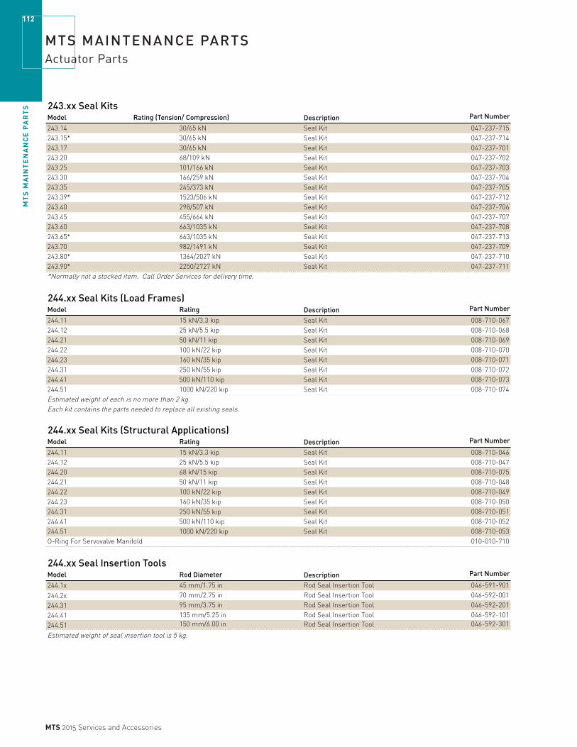
MT
S M
AIN
TE
NA
NC
E P
AR
TS
112
MTS 2015 Services and Accessories
MTS MAINTENANCE PARTSActuator Parts
243.xx Seal KitsDescription Part Number
243.14 30/65 kN Seal Kit 047-237-715243.15* 30/65 kN Seal Kit 047-237-714243.17 30/65 kN Seal Kit 047-237-701243.20 68/109 kN Seal Kit 047-237-702243.25 101/166 kN Seal Kit 047-237-703243.30 166/259 kN Seal Kit 047-237-704243.35 245/373 kN Seal Kit 047-237-705243.39* 1523/506 kN Seal Kit 047-237-712243.40 298/507 kN Seal Kit 047-237-706243.45 455/664 kN Seal Kit 047-237-707243.60 663/1035 kN Seal Kit 047-237-708243.65* 663/1035 kN Seal Kit 047-237-713243.70 982/1491 kN Seal Kit 047-237-709243.80* 1364/2027 kN Seal Kit 047-237-710243.90* 2250/2727 kN Seal Kit 047-237-711*Normally not a stocked item. Call Order Services for delivery time.
244.xx Seal Kits (Load Frames)Model Rating Description Part Number
244.11 15 kN/3.3 kip Seal Kit 008-710-067244.12 25 kN/5.5 kip Seal Kit 008-710-068244.21 50 kN/11 kip Seal Kit 008-710-069244.22 100 kN/22 kip Seal Kit 008-710-070244.23 160 kN/35 kip Seal Kit 008-710-071244.31 250 kN/55 kip Seal Kit 008-710-072244.41 500 kN/110 kip Seal Kit 008-710-073244.51 1000 kN/220 kip Seal Kit 008-710-074Estimated weight of each is no more than 2 kg.Each kit contains the parts needed to replace all existing seals.
244.xx Seal Kits (Structural Applications)Model Rating Description Part Number
244.11 15 kN/3.3 kip Seal Kit 008-710-046244.12 25 kN/5.5 kip Seal Kit 008-710-047244.20 68 kN/15 kip Seal Kit 008-710-075244.21 50 kN/11 kip Seal Kit 008-710-048244.22 100 kN/22 kip Seal Kit 008-710-049244.23 160 kN/35 kip Seal Kit 008-710-050244.31 250 kN/55 kip Seal Kit 008-710-051244.41 500 kN/110 kip Seal Kit 008-710-052244.51 1000 kN/220 kip Seal Kit 008-710-053O-Ring For Servovalve Manifold 010-010-710
244.xx Seal Insertion ToolsModel Rod Diameter Description Part Number
244.1x 45 mm/1.75 in Rod Seal Insertion Tool 046-591-901244.2x 70 mm/2.75 in Rod Seal Insertion Tool 046-592-001244.31 95 mm/3.75 in Rod Seal Insertion Tool 046-592-201244.41 135 mm/5.25 in Rod Seal Insertion Tool 046-592-101244.51 150 mm/6.00 in Rod Seal Insertion Tool 046-592-301
Estimated weight of seal insertion tool is 5 kg.
Model Rating (Tension/ Compression)
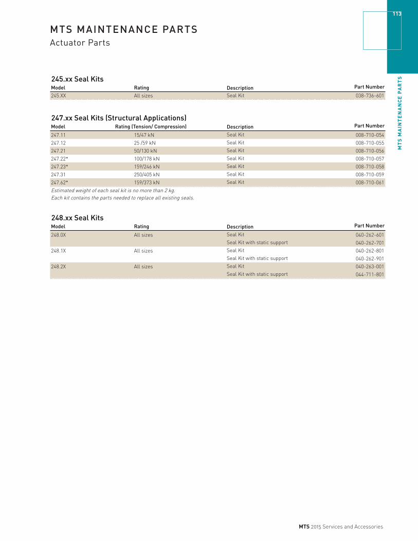
MT
S M
AIN
TE
NA
NC
E P
AR
TS
113
MTS 2015 Services and Accessories
MTS MAINTENANCE PARTSActuator Parts
245.xx Seal KitsModel Rating Description Part Number
245.XX All sizes Seal Kit 038-736-601
247.xx Seal Kits (Structural Applications)Description Part Number
247.11 15/47 kN Seal Kit 008-710-054
247.12 25 /59 kN Seal Kit 008-710-055
247.21 50/130 kN Seal Kit 008-710-056
247.22* 100/178 kN Seal Kit 008-710-057
247.23* 159/246 kN Seal Kit 008-710-058
247.31 250/405 kN Seal Kit 008-710-059
247.62* 159/373 kN Seal Kit 008-710-061
Estimated weight of each seal kit is no more than 2 kg.Each kit contains the parts needed to replace all existing seals.
248.xx Seal KitsModel Rating Description Part Number
248.0X All sizes Seal Kit 040-262-601Seal Kit with static support 040-262-701
248.1X All sizes Seal Kit 040-262-801Seal Kit with static support 040-262-901
248.2X All sizes Seal Kit 040-263-001Seal Kit with static support 044-711-801
Model Rating (Tension/ Compression)

MT
S M
AIN
TE
NA
NC
E P
AR
TS
114
MTS 2015 Services and Accessories
MTS MAINTENANCE PARTSActuator Parts
215.xx Seal KitsModel Rating Act. Assy # Part Number
215.35A 565 Nm Rotary Actuator 327308-01 033-283-101215.41A 1130 Nm Actuator 327309-01 033-305-001215.42A 2260 Nm Rotary Actuator 327310-01 033-311-901215.45A 5650 Nm Rotary Actuator 327311-01 033-282-801215.51A 11300 Nm Rotary Actuator 32731201 033-276-801
215.32B 226 Nm Rotary Actuator 362540-01 036-371-601215.35B 565 Nm Rotary Actuator 362541-01 036-371-601215.41B 1130 Nm Actuator 362542-01 036-371-601215.42B 2260 Nm Rotary Actuator 362543-01 036-371-601215.45B 5650 Nm Rotary Actuator 362544-01 036-254-701215.51B 11300 Nm Rotary Actuator 36254501 036-254-701
215.32B 226 Nm Rotary Actuator 443061-01 036-371-601215.35B 565 Nm Rotary Actuator 443062-01 036-371-601215.41B 1130 Nm Actuator 443063-01 036-371-601215.42B 2260 Nm Rotary Actuator 444064-01 036-371-601215.45B 5650 Nm Rotary Actuator 444576-01 044-527-201215.51B 11300 Nm Rotary Actuator 44457701 044-527-201
215.32C 226 Nm Rotary Actuator 474661-01 047-917-101215.35C 565 Nm Rotary Actuator 474660-01 036-371-601215.41C 1130 Nm Actuator 475286-01 036-371-601215.42C 2260 Nm Rotary Actuator 475353-01 036-371-601
244 Swivel Head/Base Spares (Old Style)Model Rating Description Part Number204/244 15–68 kN Spares Package, old style 037-410-401204/244 50–159 kN Spares Package, old style 037-410-501204/244 250–350 kN Spares Package, old style 037-410-601204/244* 500–750 kN Spares Package, old style 037-410-701*Normally not a stocked item. Call Order Services for delivery time.
Swivel Head/Base Spares Model Rating Description Part Number
249.12 25 kN/5.5 kip Spares Package 051-852-401249.20 66 kN/15 kip Spares Package 051-852-402249.23 155 kN/35 kip Spares Package 051-852-403249.31 250 kN55 kip Spares Package 051-852-404249.41 500 kN/100 kip Spares Package 051-852-405249.42 750 kN/165 kip Spares Package 051-852-406249.42S 750 kN/165 kip Spares Package 051-852-407249.51 1000 kN/220 kip Spares Package 051-852-408
Estimated weight of each is no more than 2 kg.Each kit contains the parts needed to replace all existing seals.

MT
S M
AIN
TE
NA
NC
E P
AR
TS
115
MTS 2015 Services and Accessories
MTS MAINTENANCE PARTSLoad Frame Parts
LVDTDescription Part NumberTransducer LVDT/2 in stroke 039-075-101Transducer LVDT/4 in stroke 039-075-102Transducer LVDT/6 in stroke 039-075-103Transducer LVDT/8 in stroke 039-075-111Transducer LVDT/10 in stroke 039-075-104Transducer LVDT/14 in stroke 039-075-105Transducer LVDT/20 in stroke 039-075-106
006-839-901006-839-902
Transducer LVDT/4 in stroke 006-839-903Transducer LVDT/6 in stroke 006-839-904Transducer LVDT/8 in stroke Contact MTSTransducer LVDT/10 in stroke Contact MTS
252/253/256 Servovalve-LVDT 043-229-601Each kit contains the parts needed to replace all existing seals.Estimated weight of each is no more than 2 kg.
Spares Kits DescriptionMTS Insight Part NumberSpares Kit - Insight 1K/2K 100-187-792Spares Kit - Insight 5K/10K 100-187-793Spares Kit - Insight 30K/50K 100-187-794Spares Kit - Insight 100K 100-187-795Spares Kit - Insight 150K 100-187-796Spares Kit - Insight 200K 100-187-797Spares Kit - Insight 300K 100-187-798Spares Kit - Insight 50K Wide 100-187-799Spares Kit - XLT Extensometer 100 R Std 100-187-800Spares Kit - XLT Extensometer 100 R Ext 100-187-801
311.xx Seal KitsModel Description Part Number311.11 & .21 Lift Seal Kit 032-853-001
Lock Seal Kit 032-853-301311.31 & .41 Lift Seal Kit 032-853-101
Lock Seal Kit (new style) 032-853-701
312.xx Seal KitsModel Description Part Number312.21 Lift Seal Kit 032-853-201
Lock Seal Kit 032-853-301312.31 Lift Seal Kit 032-853-401
Lock Seal Kit 032-853-501312.41 Lift Seal Kit 032-853-201
Lock Seal Kit 032-853-701Estimated weight of each is no more than 3 kg.Each kit contains the parts needed to replace the existing seals.
Transducer LVDT/2 in stroke Transformer length 3.75 inTransducer LVDT/2 in stroke Transformer length 4.63 in

MT
S M
AIN
TE
NA
NC
E P
AR
TS
116
MTS 2015 Services and Accessories
MTS MAINTENANCE PARTSLoad Frame Parts
318.xx Seal Kits (810 Series)Model Description Part Number318.10 Lift Seal Kit 040-602-101
Lock Seal Kit 040-601-80125 kN/5.5 kip Actuator Seal Kit 038-171-20150 kN/11 kip Actuator Seal Kit 038-171-101100 kN/22 kip Actuator Seal Kit 038-171-001
318.25 / 319.25 Lift Seal Kit 040-602-101Lock Seal Kit 040-601-901100 kN/22 kip Actuator Seal Kit 038-171-401250 kN/55 kip Actuator Seal Kit 038-171-301
318.50 Lift Seal Kit 040-602-201Lock Seal Kit 040-602-001250 kN/55 kip Actuator Seal Kit 038-171-601500 kN/110 kip Actuator Seal Kit 038-171-501
Estimated weight of each is no more than 10 kg. Each kit contains the parts needed to replace the existing seals.
322.xx Seal KitsModel Description Part Number322.21 Lift Seal Kit 032-853-801
Lock Seal Kit 032-853-901322.31 Lift Seal Kit 032-853-401
370.xx Seal Kits (MTS Landmark Systems)Model Description Part Number370.02 Lift Seal Kit (load frames manufactured after January 2010)100-222-825
Lift Seal Kit (load frames manufactured before January 2010)Contact MTSLock Seal Kit 100-216-44715 kN / 25 kN Linear Actuator Seal Kit 100-215-462
370.10 Lift Seal Kit (load frames manufactured after January 2010)100-222-825Lift Seal Kit (load frames manufactured before January 2010)Contact MTSLock Seal Kit 100-216-44715 kN standard and hydrostatic bearing 100-195-26725 kN standard and hydrostatic bearing 100-195-26850 kN standard and hydrostatic bearing 100-195-27167 kN standard and hydrostatic bearing (piston hub seal N/A)100-195-273100 kN standard and hydrostatic bearing 100-195-274
370.25 Lift Seal Kit (load frames manufactured after January 2010)100-222-825Lift Seal Kit (load frames manufactured before January 2010)Contact MTSLock Seal Kit 100-216-448100 kN standard and hydrostatic bearing 100-195-274250 kN standard and hydrostatic bearing 100-195-275
370.50 Lift Seal Kit (load frames manufactured after January 2010)100-222-825Lift Seal Kit (load frames manufactured before January 2010)Contact MTSLock Seal Kit 100-216-449250 kN standard and hydrostatic bearing 100-195-275500 kN standard and hydrostatic bearing 100-195-276
370.02 Seal Kits (Bionix Servohydraulic System)Model Description Part Number370.02 Lift Seal Kit (load frames manufactured after January 2010)100-222-825
Lift Seal Kit (load frames manufactured before January 2010)Contact MTSLock Seal Kit 100-216-44715 kN / 25 kN Linear Actuator Seal Kit 100-215-462Seal work on rotary actuator not recommended in the field
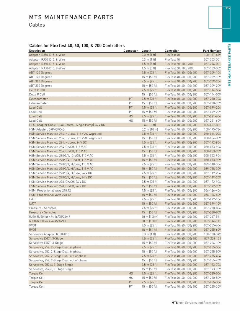
MT
S M
AIN
TE
NA
NC
E P
AR
TS
117
MTS 2015 Services and Accessories
MTS MAINTENANCE PARTSCables
Cables for FlexTest 40, 60, 100, & 200 ControllersDescription Connector Length Controller Part NumberAdapter, RJ50-D15, 4-Wire 0.3 m (1 ft) FlexTest 40 100-187-439
Adapter, RJ50-D15, 8-Wire 0.3 m (1 ft) FlexTest 40 057-303-001Adapter, RJ50-D15, 4-Wire 1.5 m (5 ft) FlexTest 60; 100; 200 057-294-001Adapter, RJ50-D15, 8-Wire 1.5 m (5 ft) FlexTest 60; 100; 200 057-303-002ADT 120 Degrees 7.5 m (25 ft) FlexTest 40; 60; 100; 200 057-309-104ADT 120 Degrees 15 m (50 ft) FlexTest 40; 60; 100; 200 057-309-109ADT 300 Degrees 7.5 m (25 ft) FlexTest 40; 60; 100; 200 057-309-204ADT 300 Degrees 15 m (50 ft) FlexTest 40; 60; 100; 200 057-309-209Delta P Cell 7.5 m (25 ft) FlexTest 40; 60; 100; 200 057-144-504Delta P Cell 15 m (50 ft) FlexTest 40; 60; 100; 200 057-144-509Extensometer PT 7.5 m (25 ft) FlexTest 40; 60; 100; 200 057-230-704Extensometer PT 15 m (50 ft) FlexTest 40; 60; 100; 200 057-230-709Load Cell PT 7.5 m (25 ft) FlexTest 40; 60; 100; 200 057-099-204Load Cell PT 15 m (50 ft) FlexTest 40; 60; 100; 200 057-099-209Load Cell MS 7.5 m (25 ft) FlexTest 40; 60; 100; 200 057-221-604Load Cell MS 15 m (50 ft) FlexTest 40; 60; 100; 200 057-221-609HPU, Adapter Cable (Dual Control, Single Pump) 24 V DC 5 m (1.5 ft) FlexTest 40; 60; 100; 200 005-407-801HSM Adapter, D9P-CPC4S 0.2 m (10 in) FlexTest 40; 60; 100; 200 100-175-734HSM Service Manifold 284, Hi/Low, 115 V AC w/ground 7.5 m (25 ft) FlexTest 40; 60; 100; 200 050-054-004HSM Service Manifold 284, Hi/Low, 115 V AC w/ground 15 m (50 ft) FlexTest 40; 60; 100; 200 050-054-009HSM Service Manifold 284, Hi/Low, 24 V DC 7.5 m (25 ft) FlexTest 40; 60; 100; 200 057-172-804HSM Service Manifold 284, On/Off, 115 V AC 7.5 m (25 ft) FlexTest 40; 60; 100; 200 050-053-904HSM Service Manifold 284, On/Off, 115 V AC 15 m (50 ft) FlexTest 40; 60; 100; 200 050-053-909HSM Service Manifold 290/3/4, On/Off, 115 V AC 7.5 m (25 ft) FlexTest 40; 60; 100; 200 050-053-904HSM Service Manifold 290/3/4, On/Off, 115 V AC 15 m (50 ft) FlexTest 40; 60; 100; 200 050-053-909HSM Service Manifold 290/3/4, Hi/Low, 115 V AC 7.5 m (25 ft) FlexTest 40; 60; 100; 200 039-718-304HSM Service Manifold 290/3/4, Hi/Low, 115 V AC 15 m (50 ft) FlexTest 40; 60; 100; 200 039-718-309HSM Service Manifold 290/3/4, Hi/Low, 24 V DC 7.5 m (25 ft) FlexTest 40; 60; 100; 200 057-119-204HSM Service Manifold 290/3/4, Hi/Low, 24 V DC 15 m (50 ft) FlexTest 40; 60; 100; 200 057-119-209HSM Service Manifold 298, On/Off, 24 V DC 7.5 m (25 ft) FlexTest 40; 60; 100; 200 057-172-904HSM Service Manifold 298, On/Off, 24 V DC 15 m (50 ft) FlexTest 40; 60; 100; 200 057-172-909HSM, Proportional Valve 298.12 7.5 m (25 ft) FlexTest 40; 60; 100; 200 056-126-404HSM, Proportional Valve 298.12 15 m (50 ft) FlexTest 40; 60; 100; 200 056-126-409LVDT 7.5 m (25 ft) FlexTest 40; 60; 100; 200 057-099-104LVDT 15 m (50 ft) FlexTest 40; 60; 100; 200 057-099-109Pressure - Sensotec 7.5 m (25 ft) FlexTest 40; 60; 100; 200 057-238-804Pressure - Sensotec 15 m (50 ft) FlexTest 40; 60; 100; 200 057-238-809RJ50-RJ50 for 494.16/25/26/47 30 m (100 ft) FlexTest 40; 60; 100; 200 057-267-511RJ50-RJ50 for 494.45/46/49 30 m (100 ft) FlexTest 40; 60; 100; 200 057-144-111RVDT 7.5 m (25 ft) FlexTest 40; 60; 100; 200 057-255-604RVDT 15 m (50 ft) FlexTest 40; 60; 100; 200 057-255-609Servovalve Adapter, RJ50-D15 0.3 m (1 ft) FlexTest 40; 60; 100; 200 100-108-342Servovalve LVDT, 3-Stage 7.5 m (25 ft) FlexTest 40; 60; 100; 200 057-204-104Servovalve LVDT, 3-Stage 15 m (50 ft) FlexTest 40; 60; 100; 200 057-204-109Servovalve, 252, 2-Stage Dual, in phase 7.5 m (25 ft) FlexTest 40; 60; 100; 200 057-255-504Servovalve, 252, 2-Stage Dual, in phase 15 m (50 ft) FlexTest 40; 60; 100; 200 057-255-509Servovalve, 252, 2-Stage Dual, out of phase 7.5 m (25 ft) FlexTest 40; 60; 100; 200 057-255-404Servovalve, 252, 2-Stage Dual, out of phase 15 m (50 ft) FlexTest 40; 60; 100; 200 057-255-409Servovalve, 252,/6 2-Stage Single 7.5 m (25 ft) FlexTest 40; 60; 100; 200 057-193-704Servovalve, 252/6, 2-Stage Single 15 m (50 ft) FlexTest 40; 60; 100; 200 057-193-709Torque Cell MS 7.5 m (25 ft) FlexTest 40; 60; 100; 200 057-230-504Torque Cell MS 15 m (50 ft) FlexTest 40; 60; 100; 200 057-230-509Torque Cell PT 7.5 m (25 ft) FlexTest 40; 60; 100; 200 057-255-304Torque Cell PT 15 m (50 ft) FlexTest 40; 60; 100; 200 057-255-309

MT
S M
AIN
TE
NA
NC
E P
AR
TS
118
MTS 2015 Services and Accessories
MTS MAINTENANCE PARTSCables
TEDS Cables for FlexTest 40, 60, 100, 200 ControllersDescription Connector Length Controller Part NumberADT 120 Degrees, TEDS Module MS 1.5 m (5 ft) FlexTest 40; 60; 100; 200 057-272-702
ADT 300 Degrees, TEDS Module MS 1.5 m (5 ft) FlexTest 40; 60; 100; 200 057-272-902
Delta P Cell, TEDS Module PT 1.5 m (5 ft) FlexTest 40; 60; 100; 200 057-273-102
Extensometer, 632.11x-90 (3 units, 1 output), 634.28, TEDS Module PT 1.5 m (5 ft) FlexTest 40; 60; 100; 200 057-272-610
Extensometer, 632.11x-90 (2 units, 1 output), 632.12, 632.23,632.24, 632.92H-05, 634.12, 634.25, TEDS Module PT 1.5 m (5 ft) FlexTest 40; 60; 100; 200 057-272-608Extensometer, 632.03, 632.13, 632.18, 632.20, 632.65, 632.85E Axial (001), 632.90, 632.92H-03, 632.92H-04, 634.11, 634.33, TEDS Module PT 1.5 m (5 ft) FlexTest 40; 60; 100; 200 057-272-606
Extensometer, 632.17. (001), 632.85F Axial (001), 634.31, TEDS Module PT 1.5 m (5 ft) FlexTest 40; 60; 100; 200 057-272-605
Extensometer, 632.02, 632.05, 632.06H-2x, 632.06H-3x (002) thru (006), 632.11x-90 (single unit), 632.19, 632.26-2x, 632.26-4x, 632.27-2x, TEDS Module PT 1.5 m (5 ft) FlexTest 40; 60; 100; 200 057-272-613Extensometer, 632.85 (002), TEDS Module PT 1.5 m (5 ft) FlexTest 40; 60; 100; 200 057-272-611Extensometer, 632.06H-3x (001), 632.17 (002), 632.27-3x, 632.29, 632.53, 632.54, 632.85 Transverse, TEDS Module PT 1.5 m (5 ft) FlexTest 40; 60; 100; 200 057-272-604
Extensometer, 632.26-3x TEDS Module PT 1.5 m (5 ft) FlexTest 40; 60; 100; 200 057-272-603
Extensometer, TEDS Module PT 1.5 m (5 ft) FlexTest 40; 60; 100; 200 057-272-602
Extensometer, TEDS Module Amphenol 1.5 m (5 ft) FlexTest 40; 60; 100; 200 057-273-302Load Cell, 661.09A/B-2X, 661.19E/F-02/04, 661.20E/F-01/02/03,
661.36C/D-03, TEDS Module PT 1.5 m (5 ft) FlexTest 40; 60; 100; 200 057-273-513
Load Cell, 661.11A/B-0X, 661.18E/F-01/02,
661.19E/F-01, 661.22C/D, 661.23E/F, 661.31E/F,
661.34E/F, TEDS Module PT 1.5 m (5 ft) FlexTest 40; 60; 100; 200 057-273-511
Load Cell, A/T, 662.10A/B, Axial, TEDS Module PT 1.5 m (5 ft) FlexTest 40; 60; 100; 200 057-273-513
Load Cell, A/T, 662.10A/B, Torsional, TEDS Module PT 1.5 m (5 ft) FlexTest 40; 60; 100; 200 057-273-813
Load Cell, A/T, 662.20C/D-01, Axial, TEDS Module PT 1.5 m (5 ft) FlexTest 40; 60; 100; 200 057-273-514
Load Cell, A/T, 662.20C/D-01, Torsional, TEDS Module PT 1.5 m (5 ft) FlexTest 40; 60; 100; 200 057-273-814
Load Cell, A/T, 662.20C/D-03/04/05/06, Axial, TEDS Module PT 1.5 m (5 ft) FlexTest 40; 60; 100; 200 057-273-512
Load Cell, 662.20C/D-03/06, Torsional, TEDS Module PT 1.5 m (5 ft) FlexTest 40; 60; 100; 200 057-273-804
Load Cell, A/T, 662.20C/D-04/05, Torsional, TEDS Module PT 1.5 m (5 ft) FlexTest 40; 60; 100; 200 057-273-803Load Cell, TEDS Module PT 1.5 m (5 ft) FlexTest 40; 60; 100; 200 057-273-502
Jumper Plug Kit 1.5 m (5 ft) FlexTest 40; 60; 100; 200 100-182-496
LVDT, TEDS Module PT 1.5 m (5 ft) FlexTest 40; 60; 100; 200 057-273-202
Pressure Sensor, TEDS Module PT 1.5 m (5 ft) FlexTest 40; 60; 100; 200 057-274-002
RVDT, TEDS Module MS 1.5 m (5 ft) FlexTest 40; 60; 100; 200 057-272-502
System Cable, ADT 120 degrees with TEDS JT to D9/D15 7.5 m (25 ft) FlexTest 40; 60; 100; 200 057-316-204
System Cable, ADT 300 degrees with TEDS JT to D9/D15 7.5 m (25 ft) FlexTest 40; 60; 100; 200 057-316-304
System Cable, Transducer with TEDS JT to RJ50 7.5 m (25 ft) FlexTest 40; 60; 100; 200 057-241-404
Tempo G, TEDS Module PT 1.5 m (5 ft) FlexTest 40; 60; 100; 200 057-274-202
Torque, TEDS Module MS 1.5 m (5 ft) FlexTest 40; 60; 100; 200 057-273-902
Torque, TEDS Module PT 1.5 m (5 ft) FlexTest 40; 60; 100; 200 057-273-802

MT
S M
AIN
TE
NA
NC
E P
AR
TS
119
MTS 2015 Services and Accessories
MTS MAINTENANCE PARTSCables
Cables for FlexTest SE & GT ControllersDescription Connector Length Controller Part NumberADT 120 Degrees 7.5 m (25 ft) FlexTest SE; FlexTest GT 056-234-804
ADT 120 Degrees 15 m (50 ft) FlexTest SE; FlexTest GT 056-234-809
ADT 300 Degrees 7.5 m (25 ft) FlexTest SE; FlexTest GT 056-253-104
ADT 300 Degrees 15 m (50 ft) FlexTest SE; FlexTest GT 056-253-109
Delta P Cell – Stability 7.5 m (25 ft) FlexTest SE; FlexTest GT 047-927-604
Delta P Cell – Stability 15 m (50 ft) FlexTest SE; FlexTest GT 047-927-609
Extensometer PT 7.5 m (25 ft) FlexTest SE; FlexTest GT 050-120-004
Extensometer PT 15 m (50 ft) FlexTest SE; FlexTest GT 050-120-009
Load Cell PT 7.5 m (25 ft) FlexTest SE; FlexTest GT 046-440-204
Load Cell PT 15 m (50 ft) FlexTest SE; FlexTest GT 046-440-209
Load Cell MS 7.5 m (25 ft) FlexTest SE; FlexTest GT 046-440-604
Load Cell MS 15 m (50 ft) FlexTest SE; FlexTest GT 046-440-609
HSM Service Manifold 284, Hi/Low, 115 V AC w/ground 7.5 m (25 ft) FlexTest SE; FlexTest GT 050-054-004
HSM Service Manifold 284, Hi/Low, 115 V AC w/ground 15 m (50 ft) FlexTest SE; FlexTest GT 050-054-009
HSM Service Manifold 284, Hi/Low, 24 V DC 7.5 m (25 ft) FlexTest SE; FlexTest GT 039-712-804
HSM Service Manifold 284, Hi/Low, 24 V DC 15 m (50 ft) FlexTest SE; FlexTest GT 039-712-809
HSM Service Manifold 284; 290/3/4 On/Off, 115 V AC 7.5 m (25 ft) FlexTest SE; FlexTest GT 050-053-904
HSM Service Manifold 284; 290/3/4 On/Off, 115 V AC 15 m (50 ft) FlexTest SE; FlexTest GT 050-053-909
HSM Service Manifold 290/3/4, Hi/Low, 115 V AC 7.5 m (25 ft) FlexTest SE; FlexTest GT 039-718-304
HSM Service Manifold 290/3/4, Hi/Low, 115 V AC 15 m (50 ft) FlexTest SE; FlexTest GT 039-718-309
HSM Service Manifold 290/3/4, Hi/Low, 24 V DC 7.5 m (25 ft) FlexTest SE; FlexTest GT 039-701-404
HSM Service Manifold 290/3/4, Hi/Low, 24 V DC 15 m (50 ft) FlexTest SE; FlexTest GT 039-701-409
HSM Service Manifold 298, On/Off, 24 V DC 7.5 m (25 ft) FlexTest SE; FlexTest GT 039-701-504
HSM Service Manifold 298, On/Off, 24 V DC 15 m (50 ft) FlexTest SE; FlexTest GT 039-701-509
HSM, Proportional Valve 298.12 7.5 m (25 ft) FlexTest SE; FlexTest GT 056-126-404
HSM, Proportional Valve 298.12 15 m (50 ft) FlexTest SE; FlexTest GT 056-126-409
LVDT 7.5 m (25 ft) FlexTest SE; FlexTest GT 046-440-304
LVDT 15 m (50 ft) FlexTest SE; FlexTest GT 046-440-309
Pressure - Sensotec 7.5 m (25 ft) FlexTest SE; FlexTest GT 056-253-004
Pressure - Sensotec 15 m (50 ft) FlexTest SE; FlexTest GT 056-253-009
Servovalve & Valve LVDT, Y Adapter 5 m (1.5 ft) FlexTest SE; FlexTest GT 039-710-501
Servovalve LVDT, 3-Stage 7.5 m (25 ft) FlexTest SE; FlexTest GT 039-708-604
Servovalve LVDT, 3-Stage 15 m (50 ft) FlexTest SE; FlexTest GT 039-708-609
Servovalve, 252, 2-Stage Dual, in phase 7.5 m (25 ft) FlexTest SE; FlexTest GT 039-708-504
Servovalve, 252, 2-Stage Dual, in phase 15 m (50 ft) FlexTest SE; FlexTest GT 039-708-509
Servovalve, 252, 2-Stage Dual, out of phase 7.5 m (25 ft) FlexTest SE; FlexTest GT 039-708-404
Servovalve, 252, 2-Stage Dual, out of phase 15 m (50 ft) FlexTest SE; FlexTest GT 039-708-409
Servovalve, 252, 2-Stage Single 7.5 m (25 ft) FlexTest SE; FlexTest GT 039-708-304
Servovalve, 252, 2-Stage Single 15 m (50 ft) FlexTest SE; FlexTest GT 039-708-309
Servovalve, 256, 3-Stage 7.5 m (25 ft) FlexTest SE; FlexTest GT 055-439-604
Servovalve, 256, 3-Stage 15 m (50 ft) FlexTest SE; FlexTest GT 055-439-609
Torque Cell PT 7.5 m (25 ft) FlexTest SE; FlexTest GT 039-704-204
Torque Cell PT 15 m (50 ft) FlexTest SE; FlexTest GT 039-704-209
Torque Cell MS 7.5 m (25 ft) FlexTest SE; FlexTest GT 051-649-504
Torque Cell MS 15 m (50 ft) FlexTest SE; FlexTest GT 051-649-509

MT
S M
AIN
TE
NA
NC
E P
AR
TS
120
MTS 2015 Services and Accessories
MTS MAINTENANCE PARTSCables & Replacement Lamps
Cables for Model 407 ControllersDescription Connector Length Controller Part Number
E-STOP to HPU Control 7.5 m (25 ft) Model 407 049-474-704
E-STOP to HPU Control 9.1 m (30 ft) Model 407 049-474-705
E-STOP, Remote 7.5 m (25 ft) Model 407 049-474-604
Extensometer PT 7.5 m (25 ft) Model 407 050-120-004
Load Cell MS 7.5 m (25 ft) Model 407 046-440-604
Load Cell PT 7.5 m (25 ft) Model 407 046-440-204
HPU Control 24 V DC 7.5 m (25 ft) Model 407 039-708-704
HPU Control 24 V DC 9.1 m (30 ft) Model 407 039-708-705
HSM Control to 292.xx Proportional HSM 9.1 m (30 ft) Model 407 049-474-205
HSM Hi/Low, 115 V AC 7.5 m (25 ft) Model 407 049-474-504
HSM Hi/Low, 24 V DC 7.5 m (25 ft) Model 407 049-474-404
HSM Hi/Low, 24 V DC 9.1 m (30 ft) Model 407 049-474-405
HSM On/Off Valve, 298.xx 7.5 m (25 ft) Model 407 049-740-304
HSM, Proportional Valve 298.12 7.5 m (25 ft) Model 407 049-474-304
LVDT 7.5 m (25 ft) Model 407 046-440-304
LVDT 9.1 m (30 ft) Model 407 046-440-305
Servovalve, 252 Dual 7.5 m (25 ft) Model 407 046-440-404
Servovalve, 252 Dual 9.1 m (30 ft) Model 407 046-440-405
Servovalve, 252 Single 7.5 m (25 ft) Model 407 046-440-104
Servovalve, 252 Single 9.1 m (30 ft) Model 407 046-440-105
System Ground Cable 7.5 m (25 ft) Model 407 039-709-204
System Ground Cable 9.1 m (30 ft) Model 407 039-709-205
Cables for FlexTest llm ControllersDescription Connector Length Controller Part Number
Load Cell MS 7.5 m (25 ft) FlexTest IIm 046-440-604
Load Cell PT 7.5 m (25 ft) FlexTest IIm 046-440-204
LVDT 7.5 m (25 ft) FlexTest IIm 046-440-304
Servovalve, 252 Dual 7.5 m (25 ft) FlexTest IIm 046-440-404
Servovalve, 252 Single 7.5 m (25 ft) FlexTest IIm 046-440-104
Replacement LampsDescription Part Number
421.21 010-076-901
436.11 (Type 334) 010-076-901
Oven Lamp 011-322-312
Estimated weight of each is no more than 2 kg.
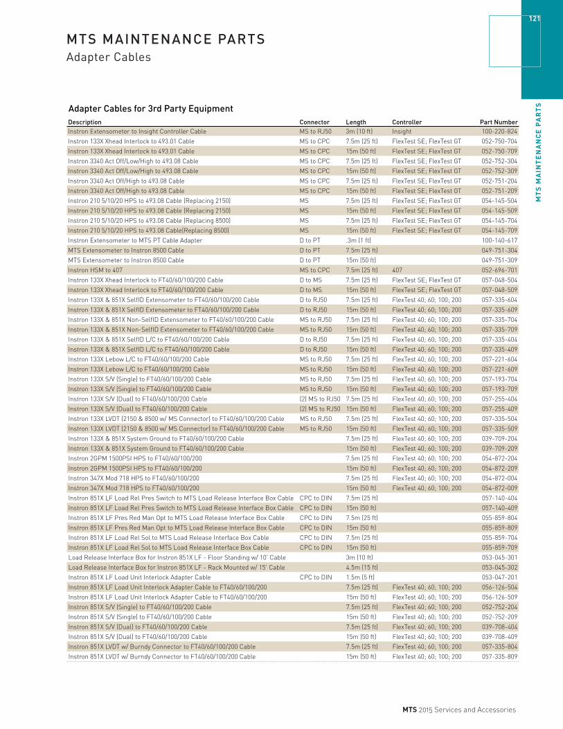
MT
S M
AIN
TE
NA
NC
E P
AR
TS
121
MTS 2015 Services and Accessories
MTS MAINTENANCE PARTSAdapter Cables
Adapter Cables for 3rd Party EquipmentDescription Connector Length Controller Part NumberInstron Extensometer to Insight Controller Cable MS to RJ50 3m (10 ft) Insight 100-220-824
Instron 133X Xhead Interlock to 493.01 Cable MS to CPC 7.5m (25 ft) FlexTest SE; FlexTest GT 052-750-704
Instron 133X Xhead Interlock to 493.01 Cable MS to CPC 15m (50 ft) FlexTest SE; FlexTest GT 052-750-709
Instron 3340 Act Off/Low/High to 493.08 Cable MS to CPC 7.5m (25 ft) FlexTest SE; FlexTest GT 052-752-304
Instron 3340 Act Off/Low/High to 493.08 Cable MS to CPC 15m (50 ft) FlexTest SE; FlexTest GT 052-752-309
Instron 3340 Act Off/High to 493.08 Cable MS to CPC 7.5m (25 ft) FlexTest SE; FlexTest GT 052-751-204
Instron 3340 Act Off/High to 493.08 Cable MS to CPC 15m (50 ft) FlexTest SE; FlexTest GT 052-751-209
Instron 210 5/10/20 HPS to 493.08 Cable (Replacing 2150) MS 7.5m (25 ft) FlexTest SE; FlexTest GT 054-145-504
Instron 210 5/10/20 HPS to 493.08 Cable (Replacing 2150) MS 15m (50 ft) FlexTest SE; FlexTest GT 054-145-509
Instron 210 5/10/20 HPS to 493.08 Cable (Replacing 8500) MS 7.5m (25 ft) FlexTest SE; FlexTest GT 054-145-704
Instron 210 5/10/20 HPS to 493.08 Cable(Replacing 8500) MS 15m (50 ft) FlexTest SE; FlexTest GT 054-145-709
Instron Extensometer to MTS PT Cable Adapter D to PT .3m (1 ft) 100-140-617
MTS Extensometer to Instron 8500 Cable D to PT 7.5m (25 ft) 049-751-304
MTS Extensometer to Instron 8500 Cable D to PT 15m (50 ft) 049-751-309
Instron HSM to 407 MS to CPC 7.5m (25 ft) 407 052-696-701
Instron 133X Xhead Interlock to FT40/60/100/200 Cable D to MS 7.5m (25 ft) FlexTest SE; FlexTest GT 057-048-504
Instron 133X Xhead Interlock to FT40/60/100/200 Cable D to MS 15m (50 ft) FlexTest SE; FlexTest GT 057-048-509
Instron 133X & 851X SelfID Extensometer to FT40/60/100/200 Cable D to RJ50 7.5m (25 ft) FlexTest 40; 60; 100; 200 057-335-604
Instron 133X & 851X SelfID Extensometer to FT40/60/100/200 Cable D to RJ50 15m (50 ft) FlexTest 40; 60; 100; 200 057-335-609
Instron 133X & 851X Non-SelfID Extensometer to FT40/60/100/200 Cable MS to RJ50 7.5m (25 ft) FlexTest 40; 60; 100; 200 057-335-704
Instron 133X & 851X Non-SelfID Extensometer to FT40/60/100/200 Cable MS to RJ50 15m (50 ft) FlexTest 40; 60; 100; 200 057-335-709
Instron 133X & 851X SelfID L/C to FT40/60/100/200 Cable D to RJ50 7.5m (25 ft) FlexTest 40; 60; 100; 200 057-335-404
Instron 133X & 851X SelfID L/C to FT40/60/100/200 Cable D to RJ50 15m (50 ft) FlexTest 40; 60; 100; 200 057-335-409
Instron 133X Lebow L/C to FT40/60/100/200 Cable MS to RJ50 7.5m (25 ft) FlexTest 40; 60; 100; 200 057-221-604
Instron 133X Lebow L/C to FT40/60/100/200 Cable MS to RJ50 15m (50 ft) FlexTest 40; 60; 100; 200 057-221-609
Instron 133X S/V (Single) to FT40/60/100/200 Cable MS to RJ50 7.5m (25 ft) FlexTest 40; 60; 100; 200 057-193-704
Instron 133X S/V (Single) to FT40/60/100/200 Cable MS to RJ50 15m (50 ft) FlexTest 40; 60; 100; 200 057-193-709
Instron 133X S/V (Dual) to FT40/60/100/200 Cable (2) MS to RJ50 7.5m (25 ft) FlexTest 40; 60; 100; 200 057-255-404
Instron 133X S/V (Dual) to FT40/60/100/200 Cable (2) MS to RJ50 15m (50 ft) FlexTest 40; 60; 100; 200 057-255-409
Instron 133X LVDT (2150 & 8500 w/ MS Connector) to FT40/60/100/200 Cable MS to RJ50 7.5m (25 ft) FlexTest 40; 60; 100; 200 057-335-504
Instron 133X LVDT (2150 & 8500 w/ MS Connector) to FT40/60/100/200 Cable MS to RJ50 15m (50 ft) FlexTest 40; 60; 100; 200 057-335-509
Instron 133X & 851X System Ground to FT40/60/100/200 Cable 7.5m (25 ft) FlexTest 40; 60; 100; 200 039-709-204
Instron 133X & 851X System Ground to FT40/60/100/200 Cable 15m (50 ft) FlexTest 40; 60; 100; 200 039-709-209
Instron 2GPM 1500PSI HPS to FT40/60/100/200 7.5m (25 ft) FlexTest 40; 60; 100; 200 054-872-204
Instron 2GPM 1500PSI HPS to FT40/60/100/200 15m (50 ft) FlexTest 40; 60; 100; 200 054-872-209
Instron 347X Mod 718 HPS to FT40/60/100/200 7.5m (25 ft) FlexTest 40; 60; 100; 200 054-872-004
Instron 347X Mod 718 HPS to FT40/60/100/200 15m (50 ft) FlexTest 40; 60; 100; 200 054-872-009
Instron 851X LF Load Rel Pres Switch to MTS Load Release Interface Box Cable CPC to DIN 7.5m (25 ft) 057-140-404
Instron 851X LF Load Rel Pres Switch to MTS Load Release Interface Box Cable CPC to DIN 15m (50 ft) 057-140-409
Instron 851X LF Pres Red Man Opt to MTS Load Release Interface Box Cable CPC to DIN 7.5m (25 ft) 055-859-804
Instron 851X LF Pres Red Man Opt to MTS Load Release Interface Box Cable CPC to DIN 15m (50 ft) 055-859-809
Instron 851X LF Load Rel Sol to MTS Load Release Interface Box Cable CPC to DIN 7.5m (25 ft) 055-859-704
Instron 851X LF Load Rel Sol to MTS Load Release Interface Box Cable CPC to DIN 15m (50 ft) 055-859-709
Load Release Interface Box for Instron 851X LF - Floor Standing w/ 10' Cable 3m (10 ft) 053-045-301
Load Release Interface Box for Instron 851X LF - Rack Mounted w/ 15' Cable 4.5m (15 ft) 053-045-302
Instron 851X LF Load Unit Interlock Adapter Cable CPC to DIN 1.5m (5 ft) 053-047-201
Instron 851X LF Load Unit Interlock Adapter Cable to FT40/60/100/200 7.5m (25 ft) FlexTest 40; 60; 100; 200 056-126-504
Instron 851X LF Load Unit Interlock Adapter Cable to FT40/60/100/200 15m (50 ft) FlexTest 40; 60; 100; 200 056-126-509
Instron 851X S/V (Single) to FT40/60/100/200 Cable 7.5m (25 ft) FlexTest 40; 60; 100; 200 052-752-204
Instron 851X S/V (Single) to FT40/60/100/200 Cable 15m (50 ft) FlexTest 40; 60; 100; 200 052-752-209
Instron 851X S/V (Dual) to FT40/60/100/200 Cable 7.5m (25 ft) FlexTest 40; 60; 100; 200 039-708-404
Instron 851X S/V (Dual) to FT40/60/100/200 Cable 15m (50 ft) FlexTest 40; 60; 100; 200 039-708-409
Instron 851X LVDT w/ Burndy Connector to FT40/60/100/200 Cable 7.5m (25 ft) FlexTest 40; 60; 100; 200 057-335-804
Instron 851X LVDT w/ Burndy Connector to FT40/60/100/200 Cable 15m (50 ft) FlexTest 40; 60; 100; 200 057-335-809

MT
S M
AIN
TE
NA
NC
E P
AR
TS
122
MTS 2015 Services and Accessories
MTS MAINTENANCE PARTSGrip Parts
641.xx Seal KitsModel Rating Description Part Number
641.35 100 kN Seal Kit/Metric (Two required) 020-718-301641.37 500 kN Seal Kit/Metric (Two required) 020-718-701641.35 100 kN Seal Kit 036-792-301641.36 250 kN Seal Kit 038-753-801641.37 500 kN Seal Kit 036-809-201641.38 1000 kN Seal Kit 038-753-901Metric grip sets have a knurled ring on the main body.
646.xx Seal KitsModel Rating Description Part Number
646.10A 100 kN/22 kip Seal Kit 038-400-501646.10B 100 kN/22 kip Seal Kit 042-739-101646.25A 250 kN/55 kip Seal Kit 038-400-701646.25B 250 kN/55 kip Seal Kit 042-739-201
647.xx Seal Kits (seals for upper and lower grip)Model Rating Description Temperature Range Part Number
647.02 25 kN/5.5 kip Seal Kit –17/+65°C (0/+150°F) 047-810-701647.02 25 kN/5.5 kip Replacement Springs 010-086-754647.02 25 kN/5.5 kip Spring Anchors 038-529-001647.02 25 kN/5.5 kip Seal Kit (high temp) –40/+175°C (–40/+350°F) 047-810-702647.02B 25 kN/5.5 kip Seal Kit –40/+120°C (–40/+250°F) 056-143-501647.02B 25 kN/5.5 kip Seal Kit (high temp) –40/+175°C (–40/+350°F) 056-143-502647.10B 100 kN/22 kip Seal Kit –17/+65°C (0/+150°F) 047-810-901647.10 100 kN/22 kip Replacement Springs 010-086-752647.10 100 kN/22 kip Spring Anchors 038-310-501647.10B 100 kN/22 kip Seal Kit (high temp) –40/+175°C (–40/+350°F) 047-810-902647.25B 250 kN/55 kip Seal Kit –17/+65°C (0/+150°F) 047-810-801647.25 250 kN/55 kip Replacement Springs 010-086-753647.25 250 kN/55 kip Spring Anchors 038-310-501647.25B 250 kN/55 kip Seal Kit (high temp) –40/+175°C (–40/+350°F) 047-810-802647.50 500 kN/110 kip Seal Kit –17/+65°C (0/+150°F) 047-811-001647.50 500 kN/110 kip Replacement Springs 010-086-753647.50 500 kN/110 kip Spring Anchors 038-310-501647.50 500 kN/110 kip Seal Kit (high temp) –40/+175°C (–40/+350°F) 047-811-002
680.xx Seal KitsModel Description Part Number
680.01 Seal Kit 040-985-901Estimated weight of each is no more than 2 kg. Each kit contains parts needed to replace all existing seals.
Electromechanical Grip PartsAdvantage Pneumatic Grip Spares Kit Part NumberSpares Kit – Advantage Pneumatic 100 N/200 N 100-044-616Spares Kit – Advantage Pneumatic Grip 2 kN 100-044-617Spares Kit – Advantage Pneumatic 10 N 100-044-618Spares Kit – Advantage Pneumatic 10 kN 100-044-619
Advantage Wedge Action Replacement KitReplacement Kit Wedge Action 30 kN/50 kN 056-011-601Replacement Kit Wedge Action 100 kN/150 kN 056-011-602
Grip Supplies and Environmental Simulation PartsGrip Supply Spares Kit Part NumberKit-Spares, Grip Supply 685.10/685.22 100-109-989
653.xx Furnace Service Kit Part NumberHeater Element Service Kit – 653.01 Furnace 056-543-201Heater Element Service Kit – 653.02 &.03 Furnace 056-543-202Heater Element Service Kit – 653.04 Furnace 056-543-203
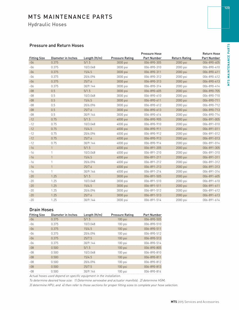
MT
S M
AIN
TE
NA
NC
E P
AR
TS
123
MTS 2015 Services and Accessories
MTS MAINTENANCE PARTSHydraulic Hoses
Pressure and Return Hoses
Fitting Size Diameter in Inches Length (ft/m) Pressure RatingPressure Hose
Part Number Return RatingReturn Hose
Part Number-06 0.375 5/1.5 3000 psi 006-890-305 2000 psi 006-890-405
-06 0.375 10/3.048 3000 psi 006-890-310 2000 psi 006-890-410
-06 0.375 15/4.5 3000 psi 006-890-311 2000 psi 006-890-411
-06 0.375 20/6.096 3000 psi 006-890-312 2000 psi 006-890-412
-06 0.375 25/7.6 3000 psi 006-890-313 2000 psi 006-890-413
-06 0.375 30/9.144 3000 psi 006-890-314 2000 psi 006-890-414
-08 0.5 5/1.5 3000 psi 006-890-605 2000 psi 006-890-705
-08 0.5 10/3.048 3000 psi 006-890-610 2000 psi 006-890-710
-08 0.5 15/4.5 3000 psi 006-890-611 2000 psi 006-890-711
-08 0.5 20/6.096 3000 psi 006-890-612 2000 psi 006-890-712
-08 0.5 25/7.6 3000 psi 006-890-613 2000 psi 006-890-713
-08 0.5 30/9.144 3000 psi 006-890-614 2000 psi 006-890-714
-12 0.75 5/1.5 4000 psi 006-890-905 2000 psi 006-891-005
-12 0.75 10/3.048 4000 psi 006-890-910 2000 psi 006-891-010
-12 0.75 15/4.5 4000 psi 006-890-911 2000 psi 006-891-011
-12 0.75 20/6.096 4000 psi 006-890-912 2000 psi 006-891-012
-12 0.75 25/7.6 4000 psi 006-890-913 2000 psi 006-891-013
-12 0.75 30/9.144 4000 psi 006-890-914 2000 psi 006-891-014
-16 1 5/1.5 4000 psi 006-891-205 2000 psi 006-891-305
-16 1 10/3.048 4000 psi 006-891-210 2000 psi 006-891-310
-16 1 15/4.5 4000 psi 006-891-211 2000 psi 006-891-311
-16 1 20/6.096 4000 psi 006-891-212 2000 psi 006-891-312
-16 1 25/7.6 4000 psi 006-891-213 2000 psi 006-891-313
-16 1 30/9.144 4000 psi 006-891-214 2000 psi 006-891-314
-20 1.25 5/1.5 3000 psi 006-891-505 2000 psi 006-891-605
-20 1.25 10/3.048 3000 psi 006-891-510 2000 psi 006-891-610
-20 1.25 15/4.5 3000 psi 006-891-511 2000 psi 006-891-611
-20 1.25 20/6.096 3000 psi 006-891-512 2000 psi 006-891-612
-20 1.25 25/7.6 3000 psi 006-891-513 2000 psi 006-891-613
-20 1.25 30/9.144 3000 psi 006-891-514 2000 psi 006-891-614
Drain HosesFitting Size Diameter in Inches Length (ft/m) Pressure Rating Part Number-06 0.375 5/1.5 100 psi 006-890-505
-06 0.375 10/3.048 100 psi 006-890-510
-06 0.375 15/4.5 100 psi 006-890-511
-06 0.375 20/6.096 100 psi 006-890-512
-06 0.375 25/7.5 100 psi 006-890-513
-06 0.375 30/9.144 100 psi 006-890-514
-08 0.500 5/1.5 100 psi 006-890-805
-08 0.500 10/3.048 100 psi 006-890-810
-08 0.500 15/4.5 100 psi 006-890-811
-08 0.500 20/6.096 100 psi 006-890-812
-08 0.500 25/7.5 100 psi 006-890-813
-08 0.500 30/9.144 100 psi 006-890-814Actual hoses used depend on specific equipment in the installation. To determine desired hose size: 1) Determine servovalve and actuator manifold; 2) determine HSM; 3) determine HPU; and 4) then refer to those sections for proper fitting sizes to complete your hose selection.
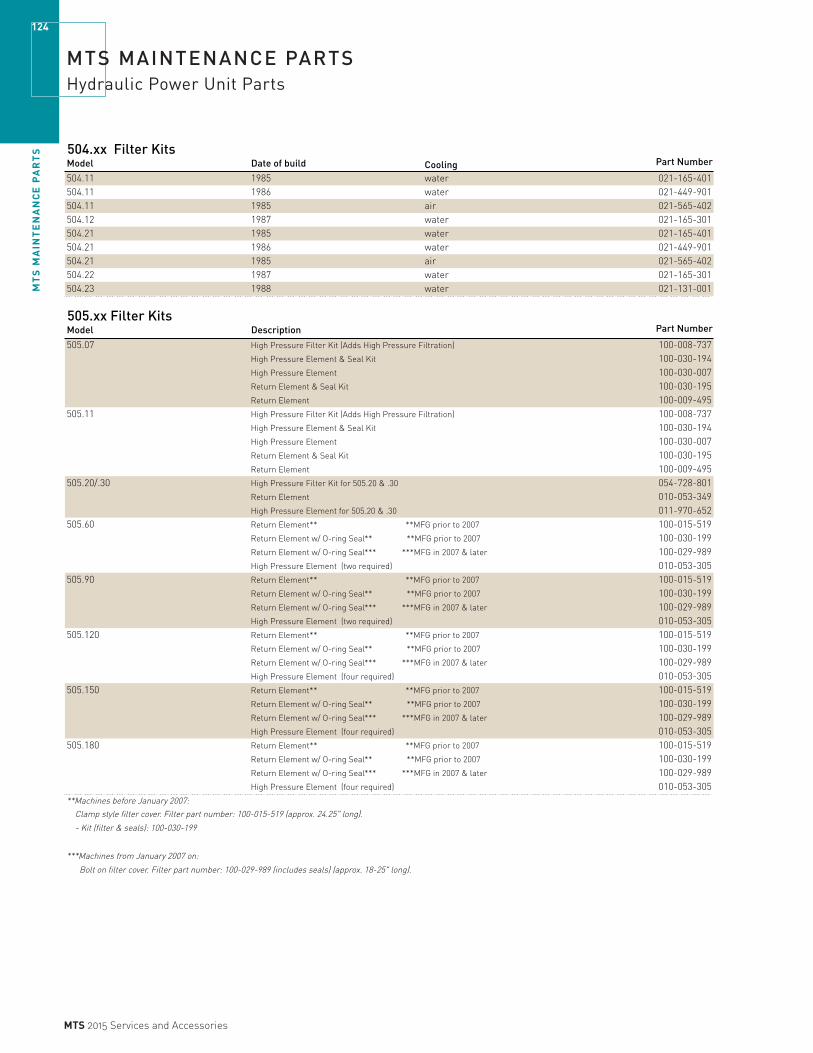
MT
S M
AIN
TE
NA
NC
E P
AR
TS
124
MTS 2015 Services and Accessories
MTS MAINTENANCE PARTSHydraulic Power Unit Parts
504.xx Filter Kits Model Date of build Cooling Part Number
504.11 1985 water 021-165-401504.11 1986 water 021-449-901504.11 1985 air 021-565-402504.12 1987 water 021-165-301504.21 1985 water 021-165-401504.21 1986 water 021-449-901504.21 1985 air 021-565-402504.22 1987 water 021-165-301504.23 1988 water 021-131-001
505.xx Filter Kits Model Description Part Number
505.07 High Pressure Filter Kit (Adds High Pressure Filtration) 100-008-737High Pressure Element & Seal Kit 100-030-194High Pressure Element 100-030-007Return Element & Seal Kit 100-030-195Return Element 100-009-495
505.11 High Pressure Filter Kit (Adds High Pressure Filtration) 100-008-737High Pressure Element & Seal Kit 100-030-194High Pressure Element 100-030-007Return Element & Seal Kit 100-030-195Return Element 100-009-495
505.20/.30 High Pressure Filter Kit for 505.20 & .30 054-728-801Return Element 010-053-349High Pressure Element for 505.20 & .30 011-970-652
505.60 100-015-519100-030-199
Return Element w/ O-ring Seal*** ***MFG in 2007 & later 100-029-989High Pressure Element (two required) 010-053-305
505.90 100-015-519100-030-199100-029-989
High Pressure Element (two required) 010-053-305505.120 100-015-519
100-030-199Return Element w/ O-ring Seal*** ***MFG in 2007 & later 100-029-989High Pressure Element (four required) 010-053-305
505.150 100-015-519100-030-199100-029-989
High Pressure Element (four required) 010-053-305505.180 100-015-519
100-030-199Return Element w/ O-ring Seal*** ***MFG in 2007 & later 100-029-989High Pressure Element (four required) 010-053-305
**Machines before January 2007:
Clamp style filter cover. Filter part number: 100-015-519 (approx. 24.25" long).
- Kit (filter & seals): 100-030-199
***Machines from January 2007 on:
Bolt on filter cover. Filter part number: 100-029-989 (includes seals) (approx. 18-25" long).
Return Element w/ O-ring Seal*** ***MFG in 2007 & later
Return Element** **MFG prior to 2007
Return Element w/ O-ring Seal** **MFG prior to 2007
Return Element** **MFG prior to 2007
Return Element w/ O-ring Seal** **MFG prior to 2007
Return Element w/ O-ring Seal** **MFG prior to 2007
Return Element** **MFG prior to 2007
Return Element w/ O-ring Seal*** ***MFG in 2007 & later
Return Element** **MFG prior to 2007
Return Element** **MFG prior to 2007
Return Element w/ O-ring Seal** **MFG prior to 2007
Return Element w/ O-ring Seal** **MFG prior to 2007

MT
S M
AIN
TE
NA
NC
E P
AR
TS
125
MTS 2015 Services and Accessories
MTS MAINTENANCE PARTSHydraulic Power Unit Parts
506.xx Filter Kits Model Description Part Number
506.00-01 Filter Element-Main Pressure 010-088-309
506.00-02 Filter Element-Inlet Pressure ** 011-068-418
All serial numbers Filter Kit-Level 1 038-752-401Filter Kit-Level 2 038-094-801Filter Kit-Level 4 038-750-901
506.01 Filter Element-Main Pressure 010-088-334
Serial numbers 100-470, Filter Element-Inlet Pressure ** 011-129-901
472-474, 481 and 482 Filter Kit-Level 1 035-843-601Filter Kit-Level 2 031-875-301Filter Kit-Level 4 031-875-401
506.01 Filter Element-Main Pressure 010-088-328
Serial numbers 471, 475-480, Filter Element-Inlet Pressure ** 011-129-901
484 and up Filter Kit-Level 1 038-750-301Filter Kit-Level 2 038-094-901Filter Kit-Level 4 038-751-001
** Cleanable element. Estimated weights: No more than 2 kg on elements; no more than 10 kg on kits.
Level 1 kits contain filters and seals to perform one maintenance requirement.
Level 2 kits contain filters and seals to perform two maintenance requirements, one cleanable filter.
Level 4 kits contain filters and seals to perform four maintenance requirements, one cleanable filter.
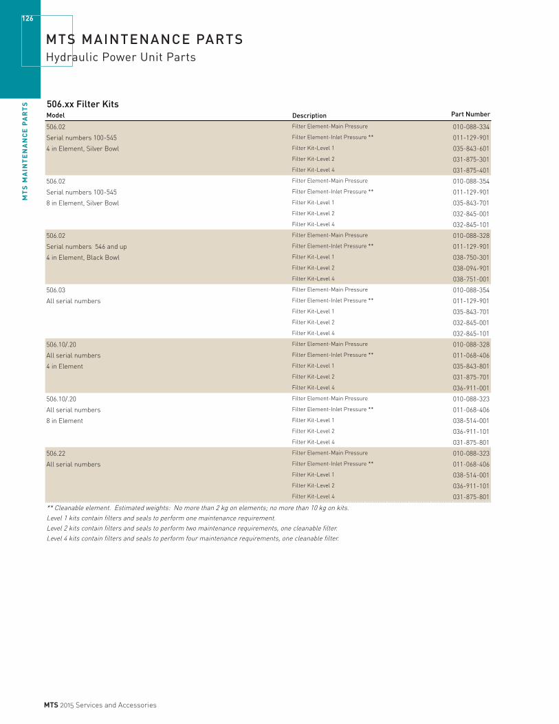
MT
S M
AIN
TE
NA
NC
E P
AR
TS
126
MTS 2015 Services and Accessories
MTS MAINTENANCE PARTSHydraulic Power Unit Parts
506.xx Filter Kits
Model Description Part Number
506.02 Filter Element-Main Pressure 010-088-334
Serial numbers 100-545 Filter Element-Inlet Pressure ** 011-129-901
4 in Element, Silver Bowl Filter Kit-Level 1 035-843-601Filter Kit-Level 2 031-875-301Filter Kit-Level 4 031-875-401
506.02 Filter Element-Main Pressure 010-088-354
Serial numbers 100-545 Filter Element-Inlet Pressure ** 011-129-901
8 in Element, Silver Bowl Filter Kit-Level 1 035-843-701Filter Kit-Level 2 032-845-001Filter Kit-Level 4 032-845-101
506.02 Filter Element-Main Pressure 010-088-328
Serial numbers 546 and up Filter Element-Inlet Pressure ** 011-129-901
4 in Element, Black Bowl Filter Kit-Level 1 038-750-301Filter Kit-Level 2 038-094-901Filter Kit-Level 4 038-751-001
506.03 Filter Element-Main Pressure 010-088-354
All serial numbers Filter Element-Inlet Pressure ** 011-129-901Filter Kit-Level 1 035-843-701Filter Kit-Level 2 032-845-001Filter Kit-Level 4 032-845-101
506.10/.20 Filter Element-Main Pressure 010-088-328
All serial numbers Filter Element-Inlet Pressure ** 011-068-406
4 in Element Filter Kit-Level 1 035-843-801Filter Kit-Level 2 031-875-701Filter Kit-Level 4 036-911-001
506.10/.20 Filter Element-Main Pressure 010-088-323
All serial numbers Filter Element-Inlet Pressure ** 011-068-406
8 in Element Filter Kit-Level 1 038-514-001Filter Kit-Level 2 036-911-101Filter Kit-Level 4 031-875-801
506.22 Filter Element-Main Pressure 010-088-323
All serial numbers Filter Element-Inlet Pressure ** 011-068-406Filter Kit-Level 1 038-514-001Filter Kit-Level 2 036-911-101Filter Kit-Level 4 031-875-801
** Cleanable element. Estimated weights: No more than 2 kg on elements; no more than 10 kg on kits.
Level 1 kits contain filters and seals to perform one maintenance requirement.
Level 2 kits contain filters and seals to perform two maintenance requirements, one cleanable filter.
Level 4 kits contain filters and seals to perform four maintenance requirements, one cleanable filter.

MT
S M
AIN
TE
NA
NC
E P
AR
TS
127
MTS 2015 Services and Accessories
MTS MAINTENANCE PARTSHydraulic Power Unit Parts
506.xx Filter Kits
Model Description Part Number
506.41 Filter Element-Main Pressure (two required) 010-053-305
Serial numbers 100-186 and 193 Filter Element-Inlet Pressure 011-068-403Filter Element-Bypass 010-088-323Filter Kit-Level 1 035-843-901Filter Kit-Level 2 031-875-901Filter Kit-Level 4 031-876-001
506.41 Filter Element-Main Pressure (two required) 010-053-305
Serial numbers 187-192, Filter Element-Inlet Pressure 011-402-819
194 and up Filter Kit-Level 1 038-750-401Filter Kit-Level 2 038-105-201Filter Kit-Level 4 038-751-101
506.51 Filter Element-Main Pressure (two required) 010-053-305
Serial numbers 100-143 Filter Element-Inlet Pressure 011-068-403Filter Element-Bypass 010-088-323Filter Kit-Level 1 035-843-901Filter Kit-Level 2 031-875-901Filter Kit-Level 4 031-876-001
506.51 Filter Element-Main Pressure (two required) 010-053-305
Serial numbers 144 and up Filter Element-Inlet Pressure 011-402-819Filter Kit-Level 1 038-750-401Filter Kit-Level 2 038-105-201Filter Kit-Level 4 038-751-101
506.52 Filter Element-Main Pressure 011-951-524
All serial numbers Filter Element-Inlet Pressure 011-178-619
506.61 Filter Element-Main Pressure (two required) 010-053-305
Serial numbers 100-189, and 205 Filter Element-Inlet Pressure 011-068-403Filter Element-Bypass 010-088-323Filter Kit-Level 1 035-843-901Filter Kit-Level 2 031-875-901Filter Kit-Level 4 031-876-001
506.61 Filter Element-Main Pressure (two required) 010-053-305
Serial numbers 190-204, Filter Element-Inlet Pressure 011-402-819
206 and up Filter Kit-Level 1 038-750-401Filter Kit-Level 2 038-105-201Filter Kit-Level 4 038-751-101
** Cleanable element. Estimated weights: No more than 2 kg on elements; no more than 10 kg on kits.
Level 1 kits contain filters and seals to perform one maintenance requirement. Level 2 kits contain filters and seals to perform two maintenance requirements, one cleanable filter. Level 4 kits contain filters and seals to perform four maintenance requirements, one cleanable filter.
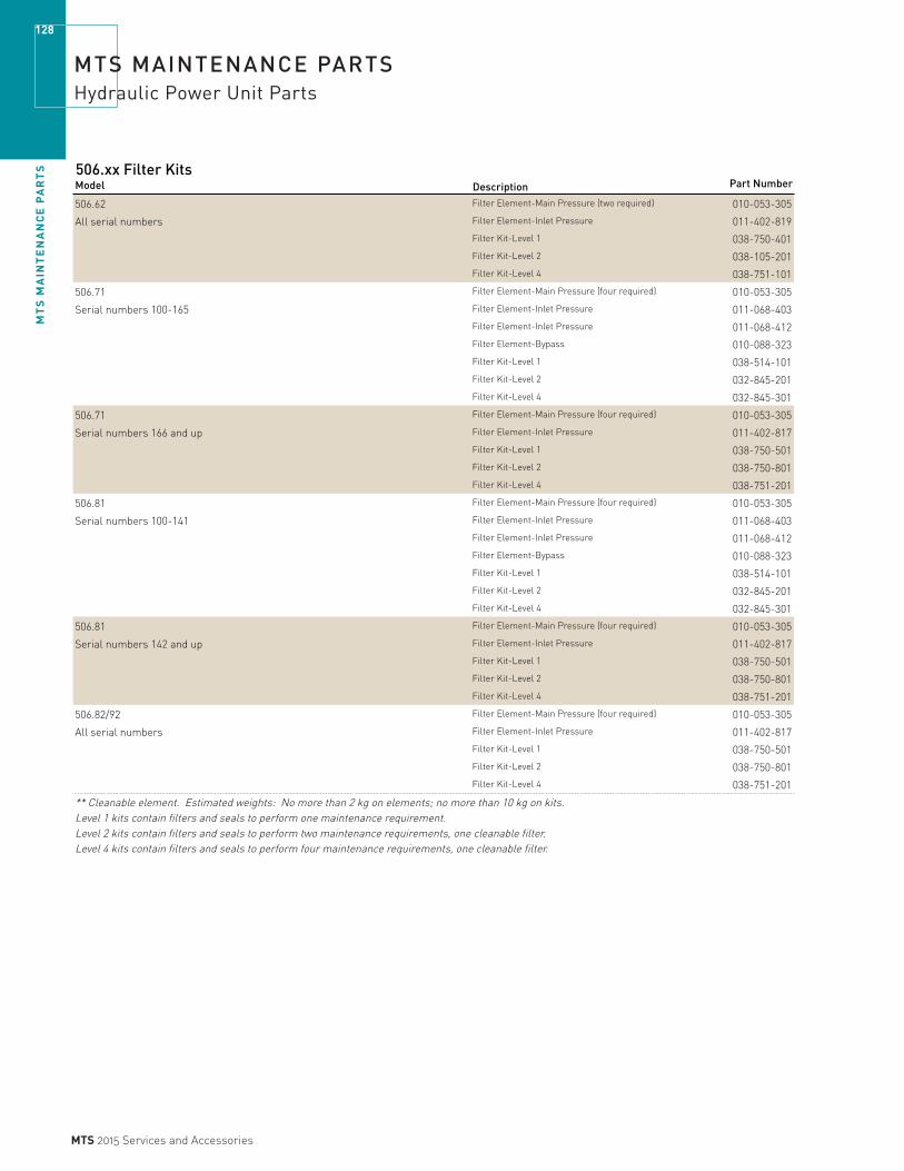
MT
S M
AIN
TE
NA
NC
E P
AR
TS
128
MTS 2015 Services and Accessories
MTS MAINTENANCE PARTSHydraulic Power Unit Parts
506.xx Filter Kits Model Description Part Number
506.62 Filter Element-Main Pressure (two required) 010-053-305
All serial numbers Filter Element-Inlet Pressure 011-402-819Filter Kit-Level 1 038-750-401Filter Kit-Level 2 038-105-201Filter Kit-Level 4 038-751-101
506.71 Filter Element-Main Pressure (four required) 010-053-305
Serial numbers 100-165 Filter Element-Inlet Pressure 011-068-403Filter Element-Inlet Pressure 011-068-412Filter Element-Bypass 010-088-323Filter Kit-Level 1 038-514-101Filter Kit-Level 2 032-845-201Filter Kit-Level 4 032-845-301
506.71 Filter Element-Main Pressure (four required) 010-053-305
Serial numbers 166 and up Filter Element-Inlet Pressure 011-402-817Filter Kit-Level 1 038-750-501Filter Kit-Level 2 038-750-801Filter Kit-Level 4 038-751-201
506.81 Filter Element-Main Pressure (four required) 010-053-305
Serial numbers 100-141 Filter Element-Inlet Pressure 011-068-403Filter Element-Inlet Pressure 011-068-412Filter Element-Bypass 010-088-323Filter Kit-Level 1 038-514-101Filter Kit-Level 2 032-845-201Filter Kit-Level 4 032-845-301
506.81 Filter Element-Main Pressure (four required) 010-053-305
Serial numbers 142 and up Filter Element-Inlet Pressure 011-402-817Filter Kit-Level 1 038-750-501Filter Kit-Level 2 038-750-801Filter Kit-Level 4 038-751-201
506.82/92 Filter Element-Main Pressure (four required) 010-053-305
All serial numbers Filter Element-Inlet Pressure 011-402-817Filter Kit-Level 1 038-750-501Filter Kit-Level 2 038-750-801Filter Kit-Level 4 038-751-201
** Cleanable element. Estimated weights: No more than 2 kg on elements; no more than 10 kg on kits.
Level 1 kits contain filters and seals to perform one maintenance requirement. Level 2 kits contain filters and seals to perform two maintenance requirements, one cleanable filter.Level 4 kits contain filters and seals to perform four maintenance requirements, one cleanable filter.

MT
S M
AIN
TE
NA
NC
E P
AR
TS
129
MTS 2015 Services and Accessories
MTS MAINTENANCE PARTSHydraulic Power Unit Parts
510.xx Filter Kits Model Description Part Number
510.10 Filter Element-Main Pressure 010-088-323
All serial numbers Filter Element-Inlet Pressure ** 011-068-416Filter Kit-Level 1 038-750-601Filter Kit-Level 2 038-105-001Filter Kit-Level 4 038-751-301
510.21/.23 – Rev A & B Filter Element-Main Pressure 011-402-827
Built through April, 1991 Filter Element-Inlet Pressure ** 011-068-417
Top Level Assy #'s – 380821-xx; 380823-xx Filter Kit-Level 1 038-750-701Filter Kit-Level 2 038-105-101Filter Kit-Level 4 038-751-401
510.21/.23 - Rev C Filter Element-Main Pressure 011-402-827
Built from May, 1991 – present Filter Element-Inlet Pressure ** 011-068-406
Top Level Assy #'s – 480821-xx; 480823-xx Filter Kit-Level 1 038-750-701Filter Kit-Level 2 048-603-101Filter Kit-Level 4 048-603-201
510.30 - Rev A Filter Element-Main Pressure 011-402-827
Built from May, 1991 – present Filter Element-Inlet Pressure ** 011-068-406
Top Level Assy #'s – 480830-xx Filter Kit-Level 1 038-750-701Filter Kit-Level 2 048-603-101Filter Kit-Level 4 048-603-201
** Cleanable element. Estimated weights: No more than 2 kg on elements; no more than 10 kg on kits.
Level 1 kits contain filters and seals to perform one maintenance requirement. Level 2 kits contain filters and seals to perform two maintenance requirements, one cleanable filter. Level 4 kits contain filters and seals to perform four maintenance requirements, one cleanable filter.
512 and 530 Filter ElementsModel Description Part Number
512.01 Filter Element 5-in spin on 011-951-521
512.04 Filter Element 5-in spin on 011-951-521
530.07 Filter Element 5-in spin on 011-951-522
530.10 Filter Element 5-in spin on 011-951-521
530.20 Filter Element 8-in 010-053-349
Seal Kit for Radial Piston Pump - RKP 63Model Description Part Number
504.11/.12/.21 Seal Kit RKP 63 Contact MTS
Please refer to the HPS manual for detailed information. Contact MTS Technical Support in case of difficulties.

MT
S M
AIN
TE
NA
NC
E P
AR
TS
130
MTS 2015 Services and Accessories
MTS MAINTENANCE PARTSHydraulic Power Unit Parts
Filter Elements / European standards
Model/Type Description Part Number
HC 9021 FUT 4H Filter Element 010-088-302
HC 9020 FDP 4H Filter Element 010-088-309
HC 9021 FDP 4H Filter Element 011-402-821
HC 9600 FDP 4H Filter Element 010-088-328
HC 9601 FDP 4H Filter Element 010-088-361
HC 9600 FDP 8H Filter Element 010-088-323
HC 9601 FDP 8H Filter Element 027-000-011
HC 9600 FDP 13H Filter Element 011-402-827
HC 9601 FDP 13H Filter Element 027-000-012
HC 9600 FDP 16H Filter Element 011-402-880
HC 9601 FDP 16H Filter Element 011-402-883
HC 9800 FDP 8H Filter Element 011-402-824
HC 9801 FDP 8H Filter Element 027-000-015
927 965 10BXLV 10-Micron Filter Element 011-395-936
927 964 03BXCW 3-Micron Filter Element 011-395-937
PER 268 H Filter Element 027-002-115
G 01448 Filter Element 027-002-246
G 01316 Filter Element 027-000-024
0060 D 003 V Filter Element 027-000-028
0060 D 005 V Filter Element 027-000-030
0110 D 005 V Filter Element 027-000-031
0160 D 005 V Filter Element 027-000-032
0330 D 005 V Filter Element 027-000-033
0660 D 005 V Filter Element 027-002-718Sika B 60 Filter Element 020-603-901
Hydrostatic-Inline
Filter Bowl Seal KitsModel/Type Description Part Number
SB 9020 SKH* Seal Kit 027-001-052
SB 9600 SKH* Seal Kit 027-001-049
SB 9800 SKH* Seal Kit 027-001-051
Heat ExchangersModel Description Part Number
504.11 Heat Exchanger 027-000-353
504.12 Heat Exchanger 027-001-973
504.21 Heat Exchanger 027-000-353
504.22 Heat Exchanger 027-001-973
504.23 Heat Exchanger 027-000-143
Upgrade of heat exchanger required. Contact MTS.Each Package contains the parts needed to replace existing seals, filter elements, and accumulators.
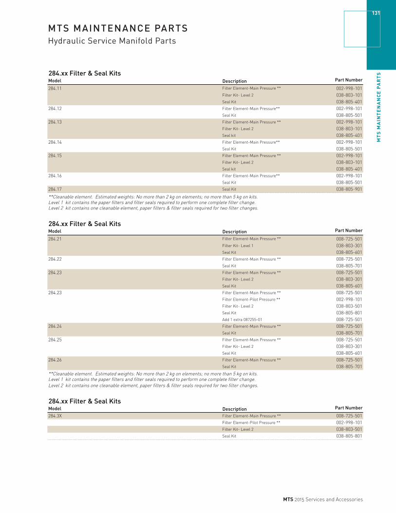
MT
S M
AIN
TE
NA
NC
E P
AR
TS
131
MTS 2015 Services and Accessories
MTS MAINTENANCE PARTSHydraulic Service Manifold Parts
284.xx Filter & Seal Kits Model Description Part Number
284.11 Filter Element-Main Pressure ** 002-998-101Filter Kit- Level 2 038-803-101Seal Kit 038-805-401
284.12 Filter Element-Main Pressure** 002-998-101Seal Kit 038-805-501
284.13 Filter Element-Main Pressure ** 002-998-101Filter Kit- Level 2 038-803-101Seal kit 038-805-401
284.14 Filter Element-Main Pressure** 002-998-101Seal Kit 038-805-501
284.15 Filter Element-Main Pressure ** 002-998-101Filter Kit- Level 2 038-803-101Seal kit 038-805-401
284.16 Filter Element-Main Pressure** 002-998-101Seal Kit 038-805-501
284.17 Seal Kit 038-805-901
**Cleanable element. Estimated weights: No more than 2 kg on elements; no more than 5 kg on kits.Level 1 kit contains the paper filters and filter seals required to perform one complete filter change.Level 2 kit contains one cleanable element, paper filters & filter seals required for two filter changes.
284.xx Filter & Seal KitsModel Description Part Number
284.21 Filter Element-Main Pressure ** 008-725-501Filter Kit- Level 1 038-803-301Seal Kit 038-805-601
284.22 Filter Element-Main Pressure ** 008-725-501Seal Kit 038-805-701
284.23 Filter Element-Main Pressure ** 008-725-501Filter Kit- Level 2 038-803-301Seal Kit 038-805-601
284.23 Filter Element-Main Pressure ** 008-725-501Filter Element-Pilot Pressure ** 002-998-101Filter Kit- Level 2 038-803-501Seal Kit 038-805-801Add 1 extra 087255-01 008-725-501
284.24 Filter Element-Main Pressure ** 008-725-501Seal Kit 038-805-701
284.25 Filter Element-Main Pressure ** 008-725-501Filter Kit- Level 2 038-803-301Seal Kit 038-805-601
284.26 Filter Element-Main Pressure ** 008-725-501Seal Kit 038-805-701
**Cleanable element. Estimated weights: No more than 2 kg on elements; no more than 5 kg on kits. Level 1 kit contains the paper filters and filter seals required to perform one complete filter change. Level 2 kit contains one cleanable element, paper filters & filter seals required for two filter changes.
284.xx Filter & Seal Kits
Model Description Part Number
284.3X Filter Element-Main Pressure ** 008-725-501Filter Element-Pilot Pressure ** 002-998-101Filter Kit- Level 2 038-803-501Seal Kit 038-805-801

MT
S M
AIN
TE
NA
NC
E P
AR
TS
132
MTS 2015 Services and Accessories
MTS MAINTENANCE PARTSHydraulic Service Manifold Parts
288.xx Filter & Seal KitsModel Flow Capacity Description Part Number
288.15 110 lpm Spares Kit 021-089-601288.16 110 lpm Spares Kit 021-161-301288.17 75/110 lpm Spares Kit 021-162-001288.25 230 lpm Spares Kit 021-094-101288.26 230 lpm Spares Kit 021-098-001288.36 350 lpm Spares Kit 021-160-801288.38 830 lpm Spares Kit 021-161-801
290.xx Filter & Seal KitsModel Description Part Number
290.11 Filter Element-Main Pressure ** 011-130-208Filter Kit – Level 2 038-926-201Seal Kit 038-926-301
290.12/.14 Filter Element-Main Pressure ** 011-130-208Filter Element-Pilot Pressure 010-088-309Filter Kit – Level 1 038-802-901Filter Kit – Level 2 038-803-601Seal Kit 038-806-001
290.13 Filter Element-Main Pressure ** 011-130-208Filter Kit – Level 2 038-926-201Seal Kit 038-806-001
**Cleanable element. Estimated weights: No more than 2 kg on elements; no more than 5 kg on kits. Level 1 kit contains the paper filters and filter seals required to perform one complete filter change. Level 2 kit contains one cleanable element, paper filters & filter seals required for two filter changes.
290.xx Filter & Seal Kits
Model Description Part Number
290.21/.22 Filter Element-Main Pressure ** 011-130-205Filter Element-Pilot Pressure 010-088-309Filter Kit – Level 1 038-802-901Filter Kit – Level 2 038-803-701Seal Kit 038-806-101
290.31 Filter Element-Main Pressure ** 011-130-205Filter Element-Pilot Pressure 010-088-309Filter Kit – Level 1 038-802-901Filter Kit – Level 2 038-803-701Seal Kit 038-806-201
290.32 Filter Element-Main Pressure ** 011-130-205Filter Element-Pilot Pressure 010-088-309Filter Kit – Level 1 038-802-901Filter Kit – Level 2 038-803-701Seal Kit 038-806-301
290.4X Seal Kit – 7-in Accumulator 011-484-307
**Cleanable element. Estimated weights: No more than 2 kg on elements; no more than 5 kg on kits.Level 1 kit contains the paper filters and filter seals required to perform one complete filter change.Level 2 kit contains one cleanable element, paper filters & filter seals required for two filter changes.
Marotta Valve Replacement KitModel Part Number24 Volt 047-792-401110 Volt 047-792-402Whenever possible, we recommend the purchase of replacement kits instead of the original Marotta valves.Replacement kits provide all the components required to replace the existing Marotta valves.Replacement kits are less expensive to purchase, less expensive to maintain, and readily available from MTS.Installation is not included in this price. Not intended for gas use.
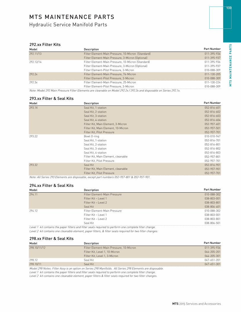
MT
S M
AIN
TE
NA
NC
E P
AR
TS
133
MTS 2015 Services and Accessories
MTS MAINTENANCE PARTSHydraulic Service Manifold Parts
292.xx Filter KitsModel Description Part Number
292.11/13 Filter Element-Main Pressure, 10-Micron (Standard) 011-395-936Filter Element-Main Pressure, 3-Micron (Optional) 011-395-937
292.12/14 Filter Element-Main Pressure, 10-Micron (Standard) 011-395-936Filter Element-Main Pressure, 3-Micron (Optional) 011-395-937Filter Element-Pilot Pressure, 3-Micron 010-088-309
292.2x Filter Element-Main Pressure, 74-Micron 011-130-205Filter Element-Pilot Pressure, 3-Micron 010-088-309
292.3x Filter Element-Main Pressure, 25-Micron 011-130-224Filter Element-Pilot Pressure, 3-Micron 010-088-309
Note: Model 292 Main Pressure Filter Elements are cleanable on Model 292.2x / 292.3x and disposable on Series 292.1x.
293.xx Filter & Seal Kits
Model Description Part Number
293.1X Seal Kit, 1-station 052-816-601Seal Kit, 2-station 052-816-602Seal Kit, 3-station 052-816-603Seal Kit, 4-station 052-816-604Filter Kit, Main Element, 3-Micron 052-957-601Filter Kit, Main Element, 10-Micron 052-957-501Filter Kit, Pilot Pressure 052-957-701
293.22 Bowl O-ring 010-010-947Seal Kit, 1-station 052-816-701Seal Kit, 2-station 052-816-801Seal Kit, 3-station 052-816-802Seal Kit, 4-station 052-816-803
052-957-801Filter Kit, Pilot Pressure 052-957-701
293.32 Seal Kit 052-816-901052-957-901
Filter Kit, Pilot Pressure 052-957-701Note: All Series 293 Elements are disposable, except part numbers 052-957-801 & 052-957-901.
294.xx Filter & Seal KitsModel Description Part Number
294.11 Filter Element-Main Pressure 010-088-302Filter Kit – Level 1 038-803-001Filter Kit – Level 2 038-803-801Seal Kit 038-806-401
294.12 Filter Element-Main Pressure 010-088-302Filter Kit – Level 1 038-803-001Filter Kit – Level 2 038-803-801Seal Kit 038-806-501
Level 1 kit contains the paper filters and filter seals required to perform one complete filter change.Level 2 kit contains one cleanable element, paper filters, & filter seals required for two filter changes.
298.xx Filter & Seal KitsModel Description Part Number
298.10/11/12 Filter Element-Main Pressure, 10-Micron 011-395-936Filter Kit, Level 1, 10-Micron 044-205-201Filter Kit, Level 1, 3-Micron 044-205-301
298.12 Seal Kit 047-651-201298.10/11 Seal Kit 047-651-301
Model 298 Notes: Filter Assy is an option on Series 298 Manifolds. All Series 298 Elements are disposable. Level 1 kit contains the paper filters and filter seals required to perform one complete filter change. Level 2 kit contains one cleanable element, paper filters & filter seals required for two filter changes.
Filter Kit, Main Element, cleanable
Filter Kit, Main Element, cleanable

MT
S M
AIN
TE
NA
NC
E P
AR
TS
134
MTS 2015 Services and Accessories
MTS MAINTENANCE PARTSFilter Elements and Flushing & Shut-Off Valves
Hydraulic Fluid Filter Elements by P/N
Material Description Part Number
Filter Element – 10 Micron* 008-725-501Filter Element – Cotton,10 in 5 Micron, Tin P 010-052-802Filter Element – Cotton,10 in 1 Micron, Tin P 010-052-824Filter Element – 10 Micron, for 506 Pumps 010-053-305Filter Element – 10 Micron 010-053-308Filter Element – 3 Micron 8 in Length 010-053-349Filter Element – 4 in Large B15=75,3000 psid,10 010-088-302Filter Element – 4 in Large B3=75,150 psid,12 gp 010-088-309Filter Element – 8 in Large B3=75,150 psid, 40 gp 010-088-323Filter Element – HC 9600 FKP 4H 010-088-328Filter Element – Dispos, 4 in B6=75,150 psid 010-088-334Filter Element – 8 in Large B6=75, 150 psid, 20 gp 010-088-354Filter Element – Paper 40 Micron 011-068-403Filter Element – Strainer 100 Mesh, 50 gpm* 011-068-406Filter Element – 40 Micron 011-068-412Filter Element – Strainer 60 Mesh, 10 gpm 011-068-416Filter Element – Strainer 200 Mesh, 20 gpm* 011-068-417Filter Element – Strainer 60 Mesh, 5 gpm* 011-068-418Filter Element – 6 in Large 74 Micron,10 gpm* 011-129-901Filter Element – 8 inLarge 74 Micron, 2000 psid* 011-130-205Filter Element – 4 in Large 74 Micron, 2000 psid* 011-130-208Filter Element – 19 in Large 25 Micron, 2000 psid 011-130-224Filter Element – Strainer 60 Mesh,100 gpm 011-178-619Filter Element – B10=75,3000 psid, 30 gpm 011-395-936Filter Element – B3=75,3000 psid, 30 gpm 011-395-937Filter Element – 39 in Large B3=75,150 psid, 175 011-402-817Filter Element – 16 in Large B3=75,150 psid, 150 011-402-819Filter Element – 13 in Large B3=75,150 psid, 011-402-827Filter Element – 8 in Large B15=75,3000 psid, 50 011-402-857Filter Element – 8 in Large B12=75,150 psid, 50 g 011-402-859Filter Element – 5 in Spin On B3=75, Microgl 011-951-521Filter Element – 5 in Spin On B11=75, Cellulo 011-951-522Filter Element – 18 in Large B3=200, 150 psid 011-951-524Filter Element – Criterion C64 IOP 100-248-238Filter Element – 8 in Large B3=200, 150 psid 011-951-528
Material Description Part NumberGuard & Filter – TestStar IIs – Model 493.01 010-087-541Filter – FlexTest SE & FlexTest 40 – Models 493.02 & 494.04 100-057-809Filter – FlexTest GT & TestStar IIm & FlexTest 100 – Models 493.10 [10-Slot] & 494.10 100-020-714Filter – FlexTest GT & Aero ST – Model 493.20 [20-Slot] 100-169-943Filter – FlexTest 60 – Model 494.06 [6-Slot] 100-168-328
100-169-890*Cleanable element. Estimated weights: No more than 2 kg on elements; no more than 5 kg on kits.
System Flushing ValvesModel For Servovalve Part Number291.01B-01 252.2x Series 031-622-001291.02B-01 252.3x Series 032-484-401291.08B-01 256.0x Series 033-874-001
Port-Shut-off-ValvesModel For Servovalve Part Number
254.02A-01 252.2x Series 031-101-001291.01B-01 Seal kit 049-160-701254.02B-01 252.3x Series 006-540-801254.02H-01 256.0x Series 046-342-501
Estimated weight of each is no more than 2 kg.
Controller Chassis Air Filter Elements by P/N
Filter – FlexTest 200 – Model 494.20 [20-Slot]

MT
S M
AIN
TE
NA
NC
E P
AR
TS
135
MTS 2015 Services and Accessories
MTS MAINTENANCE PARTSSWIFT Parts
SWIFT 20 Ultra PartsDescription Qty needed Part NumberStorage Case 1 100-025-776Beam Hole Plug Assembly 20T 4 100-026-667Beam Hole Plug Assembly 20A 4 100-019-585Outer Label SWIFT 20T 1 100-027-373Outer Label SWIFT 20A 1 100-019-296Leveling Assembly – with inclinometer* 1 100-014-450Slip Ring Assembly (with bracket and slip ring encoder) 1 100-019-727Slip Ring Assembly (with bracket and ratcheting slip ring encoder) 1 100-052-351Slip Ring Assembly (with bracket and slip ring encoder) 1 100-062-128
SWIFT 30 PC PartsDescription Qty needed Part NumberStorage Case 1 054-924-501Flexure Covers 8 054-405-901O-Ring Type Beam Hole Cover like SWIFT LT Assembly 4 Contact MTSSlip Ring Bracket Assembly – with slip ring/encoder 1 100-052-353Inner Label 1 054-286-401Outer Label 1 054-286-201Leveling Assembly – with inclinometer* 1 100-010-124
SWIFT 40 LT Parts
Description Qty needed Part NumberStorage Case 1 055-975-401Flexure Covers 8 054-947-301Beam Hole Cover Assembly 4 Contact MTSSlip Ring Bracket Assembly – with slip ring/encoder 1 100-027-993Inner Label 1 055-235-701Outer Label 1 055-235-801Leveling Assembly – with inclinometer* 1 100-010-509
SWIFT 45 MT PartsDescription Qty needed Part NumberStorage Case 1 100-211-561Beam Hole Covers 16 100-203-509Slip Ring Bracket 1 100-205-155Slip Ring/Encoder 1 100-172-139Outer Label 1 100-205-328Level Bracket Ref 700-004-754 1 100-211-570Level Bracket 1 100-211-585Extension Assembly 1 100-219-464
SWIFT 50 GLP PartsDescription Qty needed Part NumberStorage Case 1 100-162-342Beam Hole Plug 8 100-155-050Modified Set Screws needed for Beam Hole Plug 8 100-157-769Spinning Output Cable with D-style Connector-25ft 1 056-997-604SWIFT 50GLP has special low profile feedback cables 1 056-997-604Outer Label 1 100-147-491Leveling Assembly - with inclinometer 1 100-148-483Encoder/Slip Ring with D-style Connector 1 100-143-325Flat Spider Bracket 1 100-163-204Dished-in-Spider Bracket 1 100-154-409Anti-Rotate Hinge/Tube Assembly 1 100-149-775Non-Spinning Connector Adapter for Slip Ring Replacement 1 100-166-648(also requires special cable 056-493-704)Shunt Cable with D-style Connector-25ft 2 056-997-504
Modified Lug Nut-M22 10 056-984-401Lug Nut Shim Washer 10 057-090-201

MT
S M
AIN
TE
NA
NC
E P
AR
TS
136
MTS 2015 Services and Accessories
MTS MAINTENANCE PARTSSWIFT Parts
Shared Parts between ULTRA(20), PC(30) & SWIFT LT(40), & SWIFT 50GLP Description Qty needed Part Number‡Small Oval Connector Cover on top of slip ring brkt. assy. 2/spider assembly 053-323-701‡Encoder/Slip Ring – connector closer to spinning tire - non ratcheting** 1 055-554-001‡Encoder/Slip Ring – ratcheting connector** 1 100-043-522‡Shunt Cal Cover Assembly 2/spider assembly Contact MTS‡Bottom Extruded Aluminum Cover for Slip Ring assembly 1/spider assembly 053-324-001‡Anti-Rotate Hinge/Tube Assembly 1 055-862-401‡Anti-Rotate Steel Sleeve* 1 054-405-201‡Anti-Rotate Modified Delrin Ball* 1 054-405-301‡Spinning Output Cable – non ratcheting - 25 ft*** 1 054-145-004‡Spinning Output Cable – non ratcheting – Low Profile – 25 ft*** 1 056-493-604‡Spinning Output Cable – ratcheting - 25 ft*** 1 056-221-904‡Spinning Output Cable – ratcheting – Low Profile 25 ft*** 1 056-753-804‡Non-Spinning Ratcheting Output Cable – 50 ft*** 1 054-145-106‡Non-Spinning Ratcheting Output Cable – Low Profile – 50 ft*** 1 056-493-709
Comm Cable to PC 1 051-074-101
Power to TI Box 1 054-870-906
Power to TI Box – Low Profile 1 056-494-606
Fast Blow Fuse* 1 010-052-509‡Shunt Cal Cables – non ratcheting – 25 ft 1 054-871-004
Shunt Cal Cables – non ratcheting – Low Profile – 25 ft 1 056-493-504‡Shunt Cal Cable – non-spinning ratcheting for use with connector housing, 50 ft 1 054-871-105
Non-Spinning Connector Adaptor for slip ring replacement 1 100-192-580
AC/DC Lab Power Supply (for up to 4 SWIFTs): 1 054-864-903‡Lug Nut Washer for M14 or 9/16 studs depends on vehicle 055-879-401‡Lug Nut Washer for M12x1.5 or 1/2-20 studs depends on vehicle 055-522-801‡Lug Nut - M12x1.5, 1/2-20, M14x2.0 or 9/16-18 thread depends on vehicle 545-521-1xx
Mini TI Section Mini TI 1 100-182-635
Cable SWIFT 10 or 45 1 052-702-9xx
Mini Cable Adapter to SWIFT 20, 30, 40, and 50 1 100-224-052
*) Recommended spare part**) Typically only one of the three encoders/Slip rings are required.***) Typically only one of the output cables are required per transducer. ‡)Recommended spare part for the Ultra(20), PC(30), & SWIFT LT(40) only. Not for use with the SWIFT50 GLP.

MT
S M
AIN
TE
NA
NC
E P
AR
TS
137
MTS 2015 Services and Accessories
MTS MAINTENANCE PARTSFlatTrac & Rolling Road Systems Parts
Flat Trac System Endless Belts Description Part Number
Belt-Endless, Painted, FT LTR 100-047-038
Belt-Endless, Painted, FT CT Plus 100-225-198
Belt-Endless, Painted, FT 2 049-050-801
Belt-Endless, Painted, FT 1 100-064-608
Note 1: Always verify correct belt part number to specific system application
Rolling Road System Endless Belts - Uncoated Description Part Number
Belt-Endless, 0.9M, RRS 100-247-104
Belt-Endless, 1M, RRS 100-136-088
Belt-Endless, 1M, RRS 100-153-637
Belt-Endless, 1M, RRS 100-210-255Belt-Endless, 1.1M, RRS 100-153-639Belt-Endless, 1.1M, RRS 100-237-053Belt-Endless, 1.1M, RRS 100-247-105Belt-Endless, 1.1M, RRS 056-624-301Belt-Endless, 1.1M, RRS 056-624-302Belt-Endless, 1.1M, RRS 056-624-303Belt-Endless, 1.1M, RRS 056-624-304Belt-Endless, 2M, RRS 057-374-405Belt-Endless, 2M, RRS 057-374-406Belt-Endless, 2.4M, RRS 057-374-401Belt-Endless, 2.4M, RRS 057-374-402Belt-Endless, 2.4M, RRS 057-374-403Belt-Endless, 2.4M, RRS 057-374-404Belt-Endless, 2.4M, RRS 100-127-230Belt-Endless, 3.2M, RRS 100-048-656Belt-Endless, 3.2M HS, RRS 100-236-024Belt-Endless, 6.0M, RRS 100-223-993
Note 1: Always verify correct belt part number to specific system applicationNote 2: Contact MTS for special belt coating requests
Rolling Road System Air Bearings - Standard Description Part Number
AirBearing 3.0 LG Strip 100-031-076
AirBearing 6.0 LG Strip 100-014-067
AirBearing 9.0 LG Strip 100-014-068
AirBearing 12.0 LG Strip 100-014-069
Note 1: For custom system air bearings contact MTS for pricing and availability

MT
S M
AIN
TE
NA
NC
E P
AR
TS
138
MTS 2015 Services and Accessories
MTS MAINTENANCE PARTSSeries 329 Road Simulator Parts
OverviewSeries 329 Road Simulator maintenance parts kits are designed for several levels of service, from routine maintenance to repair. Replace just some of the pieces or the entire component. All kits are manufactured using the latest design features and highest quality parts for maximum performance. Most of these kits are normally stocked. Contact MTS for availability.
Component KitA component kit enables you to replace the wear parts of a fixture, commonly known as bushing/bearing kits. These are bushings and bearings that keep the fixture operating smoothly. When used as part of a routine maintenance program, these kits help to prolong the repeatability and life of your test rig.
Component Assembly KitA component assembly is designed to completely replace a given component in your test rig. This gives you a fast and convenient way to perform routine maintenance and repairs. Each component assembly comes with the appropriate bushings and bearings already installed (for attachment pins and shafts, see connecting kit). Replacing a component is simple: remove the old component and put the new one in its place.
Connecting KitThe connecting kit is designed to replace the pieces that connect two adjacent components, commonly referred to as pin kits. These kits consist of pins, shafts, and grease fittings. These parts are not included in a component assembly or kit because they are not always needed for a repair.
Material Handling TraysThe wear parts shown in the trays below are included in the Series 329 rebuild kit. These original OEM replacement parts are used to rebuild the 11 unique structural fixture assemblies used within one MTS Series 329 4DOF corner.
Factory MaintenanceNot every Series 329 Road Simulator component is listed on the following pages. There are some components that can be serviced with the use of custom-made tools and special processes available only at an MTS facility. Please contact your MTS service specialist for parts needs not found in this catalog.
Series 329 Rebuild ProgramIt’s almost like getting a brand new system. The Series 329 rebuild program was developed to make it efficient and economical to accomplish extensive routine maintenance during a single maintenance period. The Series 329 rebuild program will disassemble your corners at our factory and rebuild them to like-new condition. This program can be tailored to meet the maintenance requirements of your system. Please contact us for an evaluation and a discussion of these options.
MTS offers a planned approach for fast cycle times in completing complex 329 Rig overhauls either onsite or in the factory with our efficient 329 rebuild program. The two trays shown below contain all pin, bushings, bearings, and shims to completely rebuild all moving parts on one corner of 329 LT or PC. The trays are shipped stacked together in a box. The kits are compact and easily stored at the customer’s site for future use if desired.
Series 329 rebuild kits help organize the many small parts needed for a successful rebuild.
Small parts trays

MT
S M
AIN
TE
NA
NC
E P
AR
TS
139
MTS 2015 Services and Accessories
MTS MAINTENANCE PARTSModel 329 4 DOF Passenger Car Road Simulator Parts
To determine which part number is correct for your Series 329 Road Simulator, you must determine if you need assemblies with Lord bushings or Clevite bushings. MTS keeps detailed records of your system to help determine which bushings you have. Make sure you discuss which bushing is correct for your system when placing your order.
Guidelines for choosing the correct bushing:
• If you are replacing just one assembly, you should replace it with the same type of bushing that was in the original assembly.
• If you are replacing multiple assemblies as part of a major overhaul of your system, you should consider assemblies with Clevite bushings.
• If you decide to replace your existing Lord bushing assembly or assemblies with an assembly with Clevite bushings, you may need to adjust (reiterate) your drive files to compensate for the slightly different performance characteristics of the Clevite bushings.
1
2
9
8
10
11
65
7
3
4
Note: Some maintenance and part replacement requires special tools to complete. MTS field service can also complete these tasks on site with the appropriate tools and expertise.

MT
S M
AIN
TE
NA
NC
E P
AR
TS
140
MTS 2015 Services and Accessories
MTS MAINTENANCE PARTSModel 329 4 DOF Passenger Car Road Simulator Parts
329 Bearings
Description Part Number
Rod End Bearing, 3/4-16, R.H. Thread, 0.750 Bore 042-798-601
Rod End Bearing, 3/4-16, L.H. Thread, 0.750 Bore 042-798-602
Rod End Bearing, 3/4-16, R.H. Thread, 0.625 Bore 042-795-401
Rod End Bearing, 1/2-20, R.H. Thread, 0.500 Bore 042-798-603
329 Load Cells Description Part Number
661.57x-xx Load Cell for 329 & 329LT Longitudinal (Includes attachment screws) 048-104-273
661.57x-xx Load Cell for 329 & 329LT Lateral (Includes attachment screws) 048-102-974
661.19x-xx Load Cell-Modified for 329 Brake Actuator 440396-XX
329 Actuator Seal KitsDescription Part Number
Vertical Actuator Seal Kit for 244.20 Spcl (Static Support) 048-705-606
This Seal Kit provides seals for both the Model 244.20 Actuator and the Static Support Option.
Vertical Actuator Seal Kit for 244.22 Spcl (Static Support) 047-785-401
This Seal Kit provides seals for both the Model 244.22 Actuator and the Static Support Option.
Lateral Actuator Seal Kit for 244.12 008-710-047
Longitudinal Actuator Seal Kit for 244.21 008-710-048
Brake Actuator Seal Kit for 242.0x 042-065-404
Miscellaneous 329 PartsDescription Part Number
Water Dummy, Torso ONLY 011-860-904
Water Dummy Assembly (w/valves) 045-962-001Brake-Strut Shaft Service Kit 050-668-961Brake-Strut Bushing/Bearing Service Kit 050-668-981
Seat Mounted Steer Robot (cables & amplifier enclosure not included) 100-107-417
Dynamic Brake Intensifier (brake fluid not included, EPR seals compatible with most brake fluids) 045-233-306
Replacement Seal Kit for Dynamic Brake Intensifier 100-110-498
Dynamic Brake Intensifier Air Inlet Filter 100-130-988
HSM Pilot Pressure Filter 052-957-701
AEROSHELL14 GREASE (tube for grease gun) 011-010-225

MT
S M
AIN
TE
NA
NC
E P
AR
TS
141
MTS 2015 Services and Accessories
MTS MAINTENANCE PARTSModel 329 4 DOF Passenger Car Road Simulator Parts
329 Structural Parts
DescriptionDrawing Number Clevit P/N Lord P/N
Spindle Adapter (Component Assembly) 1 048-102-691 048-103-091
Spindle Adapter @ Vertical Strut Bearings and Bushings (Component Kit) 048-102-681 048-103-081
Spindle Adapter @ Vertical Strut Clamp and Shaft Kit (Connecting Kit) 048-102-662 048-103-062
Spindle Adapter @ Lateral Strut Clamp and Shaft Kit (Connecting Kit) 048-102-661 048-103-061
Vertical Strut Assembly (Component Assembly) 2 048-103-191 048-103-191
Vertical Strut-Bearings (Component Kit) 048-103-181 048-103-181
Vertical Strut-Pin Kit @ Center (Connecting Kit) 048-103-161 048-103-161
Vertical Strut-Special/For Limited Clearance Applications (Component Assembly) 044-038-101 044-038-101
Longitudinal Attach Beam Assembly (Component Assembly) 3 049-071-891 049-071-691
Longitudinal Attach –Bushings & Bearings (Component Kit) 049-071-881 049-071-681
Longitudinal Attach – Triangular Cast Adapters (Connecting Kit) 049-071-871 049-071-671
Longitudinal Attach – Pin Kit @ Center (Connecting Kit) 049-071-661 049-071-661
Delta Crank Assembly (Component Assembly) 4 048-102-891 048-103-391
Delta Crank @ Vertical Strut Bushing w/Bearing (Single Bushing Only) 048-102-882 048-103-382
Delta Crank @ Vertical Struts Bushing w/Bearing (Component Kit) 048-102-881 048-103-381
Delta Crank @ Vertical Bellcrank/Bearings (Component Kit) 048-102-871 048-103-371
Delta Crank @ Vertical Bellcrank/Pin Kit (Connecting Kit) 048-102-862 048-103-362
Delta Crank @ Vertical Strut/ Pin Kit (Single Pin Only) 048-102-861 048-103-361
Brake Lever (Component Assembly) 5 048-103-491 048-103-491
Brake Lever/Bearings (Component Kit) 048-103-481 048-103-481
Brake Lever/Pin Kit @ Vertical Bellcrank (Connecting Kit) 048-103-461 048-103-461
Brake Input Strut Assembly (Component Assembly) 6 048-103-591 048-103-591
Brake Input Strut/Rod End Bearing/ 3/4"-16 R.H. 042-798-601 042-798-601
Brake Input Strut/Rod End Bearing/ 3/4"-16 L.H. 042-798-602 042-798-602
Vertical Bellcrank Assembly (Component Assembly) 7 048-103-691 048-103-691
Vertical Bellcrank & Flexture Bearings (Component Kit) 048-103-681 048-103-681
Vertical Flexture Housing (Component Assembly) 048-103-671 048-103-671
Vertical Flexture Housing/Pin Kit (Connecting Kit) 048-103-662 048-103-662
Vertical Bellcrank/Pin Kit @ Pivot (Connecting Kit) 048-103-661 048-103-661
Longitudinal Bellcrank (Component Assembly) 8 048-103-791 048-103-791
Longitudinal Strut (Component Assembly) 9 048-104-291 048-103-891
Longitudinal Strut Bearings & Bushings (Component Kit) 048-104-282 048-103-882
Longitudinal Strut Bearings (Component Kit) 048-104-281 048-103-881
Longitudinal Strut Load Cells (Connecting Kit) 048-104-273 048-103-873
Longitudinal Strut Standard Housing Assy (Component Assembly) 048-104-272 048-103-872
Longitudinal Strut Swivel Housing Assy (Component Assembly) 048-104-271 048-103-871
Longitudinal Strut/Pin Kit @ Bellcrank (Connecting Kit) 048-104-261 048-103-861
See the drawing on page 139.

MT
S M
AIN
TE
NA
NC
E P
AR
TS
142
MTS 2015 Services and Accessories
MTS MAINTENANCE PARTSModel 329 4 DOF Passenger Car Road Simulator Parts
329 Structural Parts (continued)
DescriptionDrawing Number Clevit P/N Lord P/N
Lateral Strut (Component Assembly) 10 048-102-991 048-103-991
Lateral Strut Wrist Joint (Component Kit) 048-102-982
Lateral Strut Bearings & Bushings (Component Kit) 048-102-981 048-103-981
Lateral Strut Bearing Housing Assy @ Spindle (Component Assembly) 048-102-975 048-103-975
Lateral Strut Load Cell (Connecting Kit) 048-102-974 048-103-974
Lateral Strut Bearings/Bushings/Wrist (Component Kit) 048-102-973 048-103-973
Lateral Strut Bushing Housing Assy @ Bellcrank (Component Assembly) 048-102-972 048-103-972
Lateral Strut Tube & Tie Rod (Connecting Kit) 048-102-971 048-103-971
Lateral Strut Pin Kit @ Spindle (Connecting Kit) 048-102-962 048-103-962
Lateral Strut Pin Kit @ Bellcrank (Connecting Kit) 048-102-961 048-103-961
Lateral Bellcrank (Component Assembly) 11 048-104-091 048-104-091 Component Assembly: – Is usually the -x91 part numbers – Involves a preassembly of parts for fast "plug & play" and to reduce customer downtime.
Connecting Kit – Usually involves a smaller group of parts than a Component Assembly, which may or may not be preassembled. – Focus of a connecting kit is on repair or replacement of a failed part. – Customer uptime on a system is usually not as critical; involves system teardown to a single component level.
Component Kit – Involves replacement of parts with a predetermined life span. Components of this nature are all bearings, bearings, bushings, and so forth.

MT
S M
AIN
TE
NA
NC
E P
AR
TS
143
MTS 2015 Services and Accessories
MTS MAINTENANCE PARTSModel 329 6 DOF Passenger Car Road Simulator Parts
2
3
1
87
5
6
4

MT
S M
AIN
TE
NA
NC
E P
AR
TS
144
MTS 2015 Services and Accessories
MTS MAINTENANCE PARTSModel 329 6 DOF Passenger Car Road Simulator Parts
329 6 DOF Passenger Car Road Simulator Parts*The following part numbers apply to 329 6DOF Passenger Car Road Simulators purchased pre December 1, 2006.See 329 6DOF Light Truck section for purchases after this date.
Spindle Housing Assembly*Drawing Number Description Part Number
329-6DOF SVC Assembly Spindle (HSG/BRG) 1 Spindle Housing, Shafts & Bearings 056-736-692
Vertical Strut Assembly* 2 Description Part NumberVertical Strut SVC Assembly-329-6D (Strut) Vertical Struts, Bearings, and Bushings 056-737-092
Vertical Strut SVC Assembly-329-6D (BRG) Vertical Strut Assembly Bearings 056-737-082
Vertical Strut SVC Assembly-329-6D (BSHG) Vertical Strut Assembly Bushings 056-737-084
Vertical Strut SVC Assembly-329-6D (PIN) Vertical Strut Assembly Pin Kit 056-737-072Spherical Ball & Pin Upgrade Assembly Updates ball and pin to include a grease zerk for lubrication of the
ball joint056-736-972
Vertical Input Assembly* 3 Description Part Number329-6 DOF SVC Assembly (J Crank Component Kit) J-Cranks only 056-736-492
329-6 DOF SVC Assembly (J Crank SVC Assembly) J-Crank Replacement Set; (one corner) no pins 056-736-491
329-6 DOF SVC Assembly (J Crank Bearing) J-Crank Bearings and Wear Components 056-736-481
329-6 DOF SVC Assembly (Pin Kit) Vertical Input Assembly Pin Kit 056-736-471
329-6 DOF SVC Assembly (Flexure) Vertical Input Flexure and Bearings/Wear Components 056-736-392
329-6 DOF SVC Assembly (Flexure Baring) Vertical Input Flexure Bearings 056-736-381
329-6 DOF SVC Assembly (Delta Crank) Delta Crank and Bearings/Wear Components 056-736-291
329-6 DOF SVC Assembly (Delta Crank Bearing) Delta Crank Bearings 056-736-281
329-6 DOF SVC Assembly (Brake) Brake Bellcrank and Bearings/Wear Components 056-736-191
329-6 DOF SVC Assembly (Brake Bearing) Brake Bearings 056-736-181
329-6 DOF SVC Assembly (Brake Bushing) Brake Input Bushing 056-736-172
329-6 DOF SVC Assembly (Brake Lever) Brake Input Links and Bearings/Wear Components 056-736-171
Longitudinal Input Assembly* 4 Description Part Number329-6 DOF SVC Assembly Longitudinal Input (Bellcrank and Longitudinal Bellcrank and Bearings/Wear Components 056-736-791
329-6 DOF SVC Assembly Longitudinal Input (Bearing) Longitudinal Bearings and Wear Components 056-736-781
329-6 DOF SVC Assembly Longitudinal Input (Pin Kit) Longitudinal Pin Kit 056-736-771
Lateral Input Assembly* 5 Description Part Number329-6 DOF SVC Assembly Lateral 1 (Bellcrank and Bearing) Lateral 1 Bellcrank and Bearings/Wear Components 056-736-891
329-6 DOF SVC Assembly Lateral 2 (Bellcrank and Bearing) Lateral 2 Bellcrank and Bearings/Wear Components 056-736-892
329-6 DOF SVC Assembly Lateral 3 (Bellcrank and Bearing) Lateral 3 Bellcrank and Bearings/Wear Components 056-736-893
329-6 DOF SVC Assembly Lateral/Steer (Bearing) Lateral 1, Lateral 2, Lateral 3 Bearings/Wear Components 056-736-881
329-6 DOF SVC Assembly Lateral/Steer (Pin Kit) Lateral 1, Lateral 2, Lateral 3 Pin Kit 056-736-771
Longitudinal Strut Assembly* 6 Description Part NumberStrut Assembly Longitudinal SVC Assembly (Strut) Longitudinal Strut and End caps, Assembled 056-737-391Strut Assembly Longitudinal SVC Assembly (Bushing) Longitudinal Strut Bearings/Wear Components 056-737-381Strut Assembly Longitudinal SVC Assembly (Clevis) Longitudinal Strut Clevis and Bearings 056-737-382Strut Assembly Longitudinal SVC Assembly (U-Joint) Longitudinal U-Joint and Bearings 056-737-383
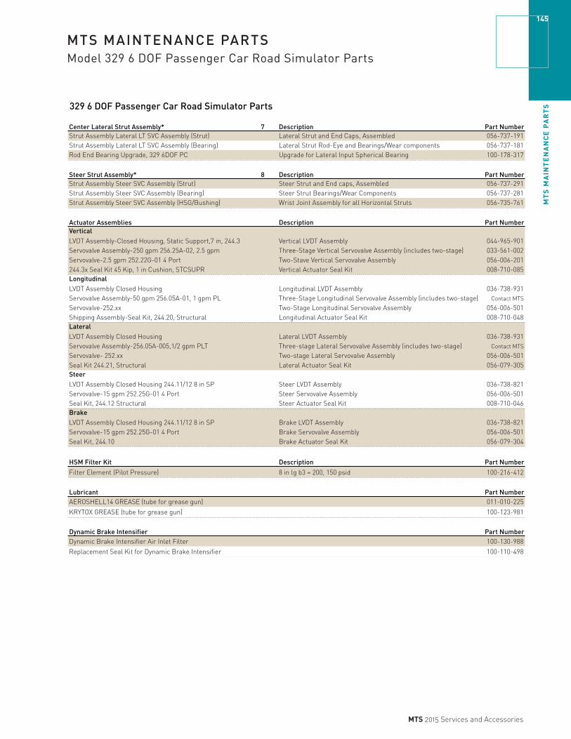
MT
S M
AIN
TE
NA
NC
E P
AR
TS
145
MTS 2015 Services and Accessories
MTS MAINTENANCE PARTSModel 329 6 DOF Passenger Car Road Simulator Parts
329 6 DOF Passenger Car Road Simulator Parts
Center Lateral Strut Assembly* 7 Description Part NumberStrut Assembly Lateral LT SVC Assembly (Strut) Lateral Strut and End Caps, Assembled 056-737-191Strut Assembly Lateral LT SVC Assembly (Bearing) Lateral Strut Rod-Eye and Bearings/Wear components 056-737-181Rod End Bearing Upgrade, 329 6DOF PC Upgrade for Lateral Input Spherical Bearing 100-178-317
Steer Strut Assembly* 8 Description Part NumberStrut Assembly Steer SVC Assembly (Strut) Steer Strut and End caps, Assembled 056-737-291Strut Assembly Steer SVC Assembly (Bearing) Steer Strut Bearings/Wear Components 056-737-281Strut Assembly Steer SVC Assembly (HSG/Bushing) Wrist Joint Assembly for all Horizontal Struts 056-735-761
Actuator Assemblies Description Part NumberVerticalLVDT Assembly-Closed Housing, Static Support,7 in, 244.3 Vertical LVDT Assembly 044-965-901Servovalve Assembly-250 gpm 256.25A-02, 2.5 gpm Three-Stage Vertical Servovalve Assembly (includes two-stage) 033-561-002Servovalve-2.5 gpm 252.22G-01 4 Port Two-Stave Vertical Servovalve Assembly 056-006-201244.3x Seal Kit 45 Kip, 1 in Cushion, STCSUPR Vertical Actuator Seal Kit 008-710-085LongitudinalLVDT Assembly Closed Housing Longitudinal LVDT Assembly 036-738-931Servovalve Assembly-50 gpm 256.05A-01, 1 gpm PL Three-Stage Longitudinal Servovalve Assembly (includes two-stage) Contact MTS
Servovalve-252.xx Two-Stage Longitudinal Servovalve Assembly 056-006-501Shipping Assembly-Seal Kit, 244.20, Structural Longitudinal Actuator Seal Kit 008-710-048LateralLVDT Assembly Closed Housing Lateral LVDT Assembly 036-738-931Servovalve Assembly-256.05A-005,1/2 gpm PLT Three-stage Lateral Servovalve Assembly (includes two-stage) Contact MTS
Servovalve- 252.xx Two-stage Lateral Servovalve Assembly 056-006-501Seal Kit 244.21, Structural Lateral Actuator Seal Kit 056-079-305SteerLVDT Assembly Closed Housing 244.11/12 8 in SP Steer LVDT Assembly 036-738-821Servovalve-15 gpm 252.25G-01 4 Port Steer Servovalve Assembly 056-006-501Seal Kit, 244.12 Structural Steer Actuator Seal Kit 008-710-046BrakeLVDT Assembly Closed Housing 244.11/12 8 in SP Brake LVDT Assembly 036-738-821Servovalve-15 gpm 252.25G-01 4 Port Brake Servovalve Assembly 056-006-501Seal Kit, 244.10 Brake Actuator Seal Kit 056-079-304
HSM Filter Kit Description Part Number
Filter Element (Pilot Pressure) 8 in lg b3 = 200, 150 psid 100-216-412
Lubricant Part NumberAEROSHELL14 GREASE (tube for grease gun) 011-010-225
KRYTOX GREASE (tube for grease gun) 100-123-981
Dynamic Brake Intensifier Part NumberDynamic Brake Intensifier Air Inlet Filter 100-130-988
Replacement Seal Kit for Dynamic Brake Intensifier 100-110-498
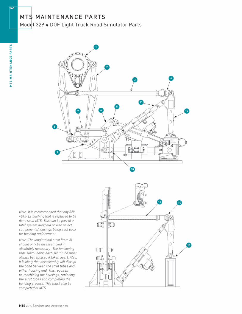
MT
S M
AIN
TE
NA
NC
E P
AR
TS
146
MTS 2015 Services and Accessories
MTS MAINTENANCE PARTSModel 329 4 DOF Light Truck Road Simulator Parts
1
2
3 4
12
56
11
8
7
9
10
13 14
15
Note: It is recommended that any 329 4DOF LT bushing that is replaced to be done so at MTS. This can be part of a total system overhaul or with select components/housings being sent back for bushing replacement.
Note: The longitudinal strut (item 3) should only be disassembled if absolutely necessary. The tensioning rods surrounding each strut tube must always be replaced if taken apart. Also, it is likely that disassembly will disrupt the bond between the strut tubes and either housing end. This requires re-machining the housings, replacing the strut tubes and completing the bonding process. This must also be completed at MTS.
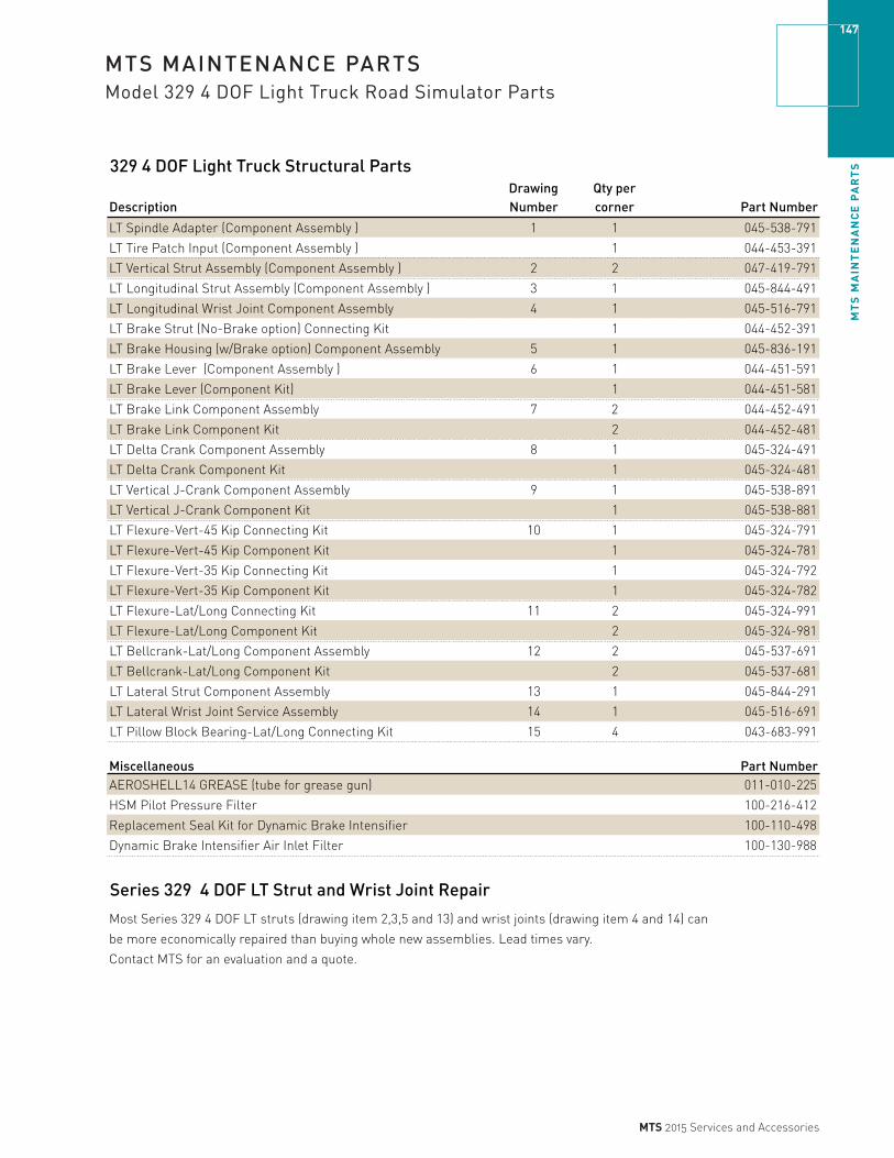
MT
S M
AIN
TE
NA
NC
E P
AR
TS
147
MTS 2015 Services and Accessories
MTS MAINTENANCE PARTSModel 329 4 DOF Light Truck Road Simulator Parts
329 4 DOF Light Truck Structural Parts
DescriptionDrawing Number
Qty per corner Part Number
LT Spindle Adapter (Component Assembly ) 1 1 045-538-791
LT Tire Patch Input (Component Assembly ) 1 044-453-391
LT Vertical Strut Assembly (Component Assembly ) 2 2 047-419-791
LT Longitudinal Strut Assembly (Component Assembly ) 3 1 045-844-491
LT Longitudinal Wrist Joint Component Assembly 4 1 045-516-791
LT Brake Strut (No-Brake option) Connecting Kit 1 044-452-391
LT Brake Housing (w/Brake option) Component Assembly 5 1 045-836-191
LT Brake Lever (Component Assembly ) 6 1 044-451-591
LT Brake Lever (Component Kit) 1 044-451-581
LT Brake Link Component Assembly 7 2 044-452-491
LT Brake Link Component Kit 2 044-452-481
LT Delta Crank Component Assembly 8 1 045-324-491
LT Delta Crank Component Kit 1 045-324-481
LT Vertical J-Crank Component Assembly 9 1 045-538-891
LT Vertical J-Crank Component Kit 1 045-538-881
LT Flexure-Vert-45 Kip Connecting Kit 10 1 045-324-791
LT Flexure-Vert-45 Kip Component Kit 1 045-324-781
LT Flexure-Vert-35 Kip Connecting Kit 1 045-324-792
LT Flexure-Vert-35 Kip Component Kit 1 045-324-782
LT Flexure-Lat/Long Connecting Kit 11 2 045-324-991
LT Flexure-Lat/Long Component Kit 2 045-324-981
LT Bellcrank-Lat/Long Component Assembly 12 2 045-537-691
LT Bellcrank-Lat/Long Component Kit 2 045-537-681
LT Lateral Strut Component Assembly 13 1 045-844-291
LT Lateral Wrist Joint Service Assembly 14 1 045-516-691
LT Pillow Block Bearing-Lat/Long Connecting Kit 15 4 043-683-991
Miscellaneous Part NumberAEROSHELL14 GREASE (tube for grease gun) 011-010-225
HSM Pilot Pressure Filter 100-216-412
Replacement Seal Kit for Dynamic Brake Intensifier 100-110-498
Dynamic Brake Intensifier Air Inlet Filter 100-130-988
Series 329 4 DOF LT Strut and Wrist Joint Repair
Most Series 329 4 DOF LT struts (drawing item 2,3,5 and 13) and wrist joints (drawing item 4 and 14) can
be more economically repaired than buying whole new assemblies. Lead times vary.
Contact MTS for an evaluation and a quote.

MT
S M
AIN
TE
NA
NC
E P
AR
TS
148
MTS 2015 Services and Accessories
MTS MAINTENANCE PARTSModel 329 6 DOF Light Truck Road Simulator Parts
2
3
1
87
5
6
4

MT
S M
AIN
TE
NA
NC
E P
AR
TS
149
MTS 2015 Services and Accessories
MTS MAINTENANCE PARTSModel 329 6 DOF Light Truck Road Simulator Parts
329 6 DOF Light Truck Road Simulator Parts*The following part numbers apply to 329 6DOF Light Truck Road Simulators purchased pre September 1, 2009 and 329 6DOF Passenger Car Road Simulators (excluding**) purchased between December 1, 2006 and September 1, 2009.
Spindle Housing Assembly* Drawing Number Description Part Number
329-6 DOF SVC Assembly Spindle (Housing/Bearing) 1 Spindle Housing, Shafts & Bearings 056-736-691
Vertical Strut Assembly* 2 Description Part NumberVertical Strut SVC Assembly-329-6D (Pin) Vertical Strut Assembly Pin Kit 057-460-372
Vertical Strut SVC Assembly-329-6D (Bearing) Vertical Strut Assembly Bearings 057-460-382
Vertical Strut SVC Assembly-329-6D (Bushing) Vertical Strut Assembly Bushings 057-460-384
Vertical Strut SVC Assembly-329-6D (RF/LR Strut) Vertical Struts, Bearings, and Bushings 057-460-391
Vertical Strut SVC Assembly-329-6D (LF/RR Strut) Vertical Struts, Bearings, and Bushings 057-460-392
Vertical Input Assembly* 3 Description Part Number
329-6 DOF SVC Assembly (J Crank Component Kit) J-Crank only 056-736-492
329-6 DOF SVC Assembly (J Crank SVC Assembly) J-Crank Replacement Set; (one corner) no pins 056-736-491
329-6 DOF SVC Assembly (J Crank Bearing) J-Crank Bearings and Wear Components 056-736-481
329-6 DOF SVC Assembly (Pin Kit) Vertical Input Assembly Pin Kit 056-736-471
329-6 DOF SVC Assembly (Flexure)** Vertical Input Flexure and Bearings/Wear Components 056-736-391
329-6 DOF SVC Assembly (Flexure Bearing) Vertical Input Flexure Bearings 056-736-381
329-6 DOF SVC Assembly (Delta Crank) Delta Crank and Bearings/Wear Components 056-736-291
329-6 DOF SVC Assembly (Delta Crank Bearing) Delta Crank Bearings 056-736-281
329-6 DOF SVC Assembly (Brake) Brake Bellcrank and Bearings/Wear Components 056-736-191
329-6 DOF SVC Assembly (Brake) Brake Bearings 056-736-181
329-6 DOF SVC Assembly (Brake Bushing) Brake Input Bushing 056-736-172
329-6 DOF SVC Assembly (Brake Lever) Brake Input Links and Bearings/Wear Components 056-736-171
Longitudinal Input Assembly* 4 Description Part Number329-6 DOF SVC Assembly Longitudinal Input (Bellcrank and Longitudinal Bellcrank and Bearings/Wear Components 056-736-791
329-6 DOF SVC Assembly Longitudinal Input (Bearing) Longitudinal Bearings and Wear Components 056-736-781
329-6 DOF SVC Assembly Longitudinal Input (Pin Kit) Longitudinal Pin Kit 056-736-771
Lateral Input Assembly* 5 Description Part Number
329-6 DOF SVC Assembly Lateral 1 (Bellcrank and Bearing) Lateral 1 Bellcrank and Bearings/Wear Components 056-736-891
329-6 DOF SVC Assembly Lateral 2 (Bellcrank and Bearing) Lateral 2 Bellcrank and Bearings/Wear Components 056-736-892
329-6 DOF SVC Assembly Lateral 3 (Bellcrank and Bearing) Lateral 3 Bellcrank and Bearings/Wear Components 056-736-893
329-6 DOF SVC Assembly Lateral/Steer (Bearing) Lateral 1, Lateral 2, Lateral 3 Bearings/Wear Components 056-736-881
329-6 DOF SVC Assembly Lateral/Steer (Pin Kit) Lateral 1, Lateral 2, Lateral 3 Pin Kit 056-736-871
Longitudinal Strut Assembly* 6 Description Part Number
Strut Assembly Longitudinal SVC Assembly (Strut) Longitudinal Strut and End caps, Assembled 056-735-791
Strut Assembly Longitudinal SVC Assembly (U-Joint) Longitudinal Joint Assembly with beaings/pins 100-219-013
Strut Assembly Longitudinal SVC Assembly (Pin) Longitudinal Strut Pin Kit 056-735-772
Strut Assembly Longitudinal SVC Assembly (Bearing) 056-735-781
Strut Assembly Longitudinal SVC Assembly (Clevis) 056-735-783
Strut Assembly Longitudinal SVC Assembly (U-Joint) 056-735-783

MT
S M
AIN
TE
NA
NC
E P
AR
TS
150
MTS 2015 Services and Accessories
MTS MAINTENANCE PARTSModel 329 6 DOF Light Truck Road Simulator Parts
329 6 DOF Light Truck Road Simulator Parts
Drawing Number
Center Lateral Strut Assembly* 7 Description Part NumberStrut Assembly Lateral LT SVC Assembly (Strut) Lateral Strut and End caps, Assembled 056-735-991
Strut Assembly Lateral LT SVC Assembly (Bearing) Lateral Strut Rod-Eye and Bearings/Wear Components 056-735-981
Rod End Bearing Upgrade, 329 6DOF LT Upgrade for Lateral Input Spherical Bearing 100-178-334
Steer Strut Assembly* 8 Description Part NumberStrut Assembly Steer SVC Assembly (Strut) Steer Strut and End caps, Assembled 056-735-891
Strut Assembly Steer SVC Assembly (Bearing) Steer Strut Bearings/Wear Components 056-735-881
Strut Assembly Steer SVC Assembly (Housing/Bushing) Wrist Joint Assembly for all Horizontal Struts 056-735-761
Actuator Assembly* Description Part NumberVertical**
LVDT Assembly-Closed Housing, Static Support, 7 in, 244.3 Vertical LVDT Assembly 045-362-001
Servovalve Assembly-250 gpm 256.25A-02, 2.5gpm Three-Stage Vertical Servovalve Assembly (includes two-stage) 033-561-002
Servovalve-2.5 gpm 252.22G-01 4 Port Two-Stave Vertical Servovalve Assembly 056-006-201
244.3x Seal Kit 45 Kip, 1 in Cushion, Static Support Vertical Actuator Seal Kit 048-978-504Longitudinal**
LVDT Assembly Closed Housing Longitudinal LVDT Assembly 036-738-931
Servovalve Assembly-50gpm 256.05A-01,1 gpm PL Three-stage Longitudinal Servovalve Assembly (includes two-stage) 033-366-501
Servovalve-252.xx Two-stage Longitudinal Servovalve Assembly 056-006-101
Shipping Assembly-Seal Kit, 244.20, Structural Longitudinal Actuator Seal Kit 008-710-075Lateral**
LVDT Assembly Closed Housing Lateral LVDT Assembly 036-738-931
Servovalve Assembly-256.05A-005, 1/2 gpm PLT 033-366-508
Servovalve- 252.xx Two-stage Lateral Servovalve Assembly 056-348-201
Seal Kit 244.21, Structural Lateral Actuator Seal Kit 008-710-048Steer**
LVDT Assembly-Closed Housing 244.11/12 8 in SP Steer LVDT Assembly 036-738-821
Servovalve-15 gpm 252.25G-01 4 Port Steer Servovalve Assembly 056-006-501
Seal Kit, 244.12 Structural Steer Actuator Seal Kit 008-710-047Brake**
LVDT Assembly-Closed Housing 244.11/12 8 in SP Brake LVDT Assembly 036-738-821
Servovalve-15 gpm 252.25G-01 4 Port Brake Servovalve Assembly 056-006-501
Seal Kit, 244.10 Brake Actuator Seal Kit 048-705-609
HSM Filter Kit Description Part NumberFilter Element (Pilot Pressure) 8 in lg b3 = 200, 150 psid 100-216-412
Lubricant Part NumberAEROSHELL14 GREASE (tube for grease gun) 011-010-225
KRYTOX GREASE (tube for grease gun) 100-123-981
Dynamic Brake Intensifier Part NumberDynamic Brake Intensifier Air Inlet Filter 100-130-988
Replacement Seal Kit foor Dynamic Intensifier 100-110-498
Three-Stage Lateral Servovalve Assembly (includes two-stage)
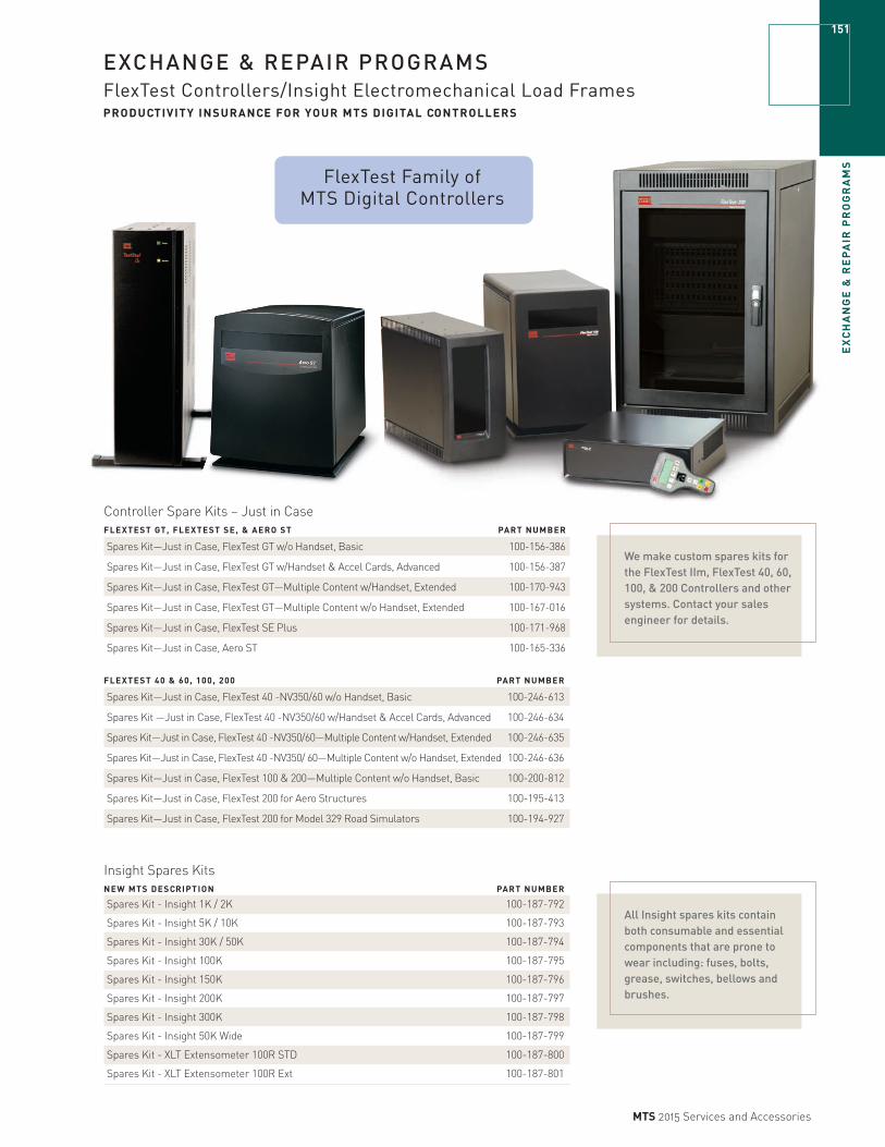
EX
CH
AN
GE
& R
EP
AIR
PR
OG
RA
MS
151
MTS 2015 Services and Accessories
EXCHANGE & REPAIR PROGRAMSFlexTest Controllers/Insight Electromechanical Load Frames PRODUCTIVITY INSURANCE FOR YOUR MTS DIGITAL CONTROLLERS
Controller Spare Kits – Just in CaseFLEXTEST GT, FLEXTEST SE, & AERO ST PART NUMBER
Spares Kit—Just in Case, FlexTest GT w/o Handset, Basic 100-156-386
Spares Kit—Just in Case, FlexTest GT w/Handset & Accel Cards, Advanced 100-156-387
Spares Kit—Just in Case, FlexTest GT—Multiple Content w/Handset, Extended 100-170-943
Spares Kit—Just in Case, FlexTest GT—Multiple Content w/o Handset, Extended 100-167-016
Spares Kit—Just in Case, FlexTest SE Plus 100-171-968
Spares Kit—Just in Case, Aero ST 100-165-336
FLEXTEST 40 & 60, 100, 200 PART NUMBER
Spares Kit—Just in Case, FlexTest 40 -NV350/60 w/o Handset, Basic 100-246-613
Spares Kit —Just in Case, FlexTest 40 -NV350/60 w/Handset & Accel Cards, Advanced 100-246-634
Spares Kit—Just in Case, FlexTest 40 -NV350/60—Multiple Content w/Handset, Extended 100-246-635
Spares Kit—Just in Case, FlexTest 40 -NV350/ 60—Multiple Content w/o Handset, Extended 100-246-636
Spares Kit—Just in Case, FlexTest 100 & 200—Multiple Content w/o Handset, Basic 100-200-812
Spares Kit—Just in Case, FlexTest 200 for Aero Structures 100-195-413
Spares Kit—Just in Case, FlexTest 200 for Model 329 Road Simulators 100-194-927
We make custom spares kits for the FlexTest IIm, FlexTest 40, 60, 100, & 200 Controllers and other systems. Contact your sales engineer for details.
FlexTest Family of MTS Digital Controllers
Insight Spares KitsNEW MTS DESCRIPTION PART NUMBER
Spares Kit - Insight 1K / 2K 100-187-792
Spares Kit - Insight 5K / 10K 100-187-793
Spares Kit - Insight 30K / 50K 100-187-794
Spares Kit - Insight 100K 100-187-795
Spares Kit - Insight 150K 100-187-796
Spares Kit - Insight 200K 100-187-797
Spares Kit - Insight 300K 100-187-798
Spares Kit - Insight 50K Wide 100-187-799
Spares Kit - XLT Extensometer 100R STD 100-187-800
Spares Kit - XLT Extensometer 100R Ext 100-187-801
All Insight spares kits contain both consumable and essential components that are prone to wear including: fuses, bolts, grease, switches, bellows and brushes.

EX
CH
AN
GE
& R
EP
AIR
PR
OG
RA
MS
152
MTS 2015 Services and Accessories
EXCHANGE & REPAIR PROGRAMSElectronics
Electronic Exchange ProgramThe MTS electronic exchange program provides a cost-effective, quick turnaround, replacement option for electronic boards. You can purchase a fully warranted and tested product in exchange for your failed unit.
FEATURES » Good-as-new performance for less than replacement
price
» Shipment within 24 hours (Monday–Friday), if item is in stock
» A fixed price for your repair
» A 12 month warranty
» The latest product revision levels
» Each product is cosmetically remanufactured
» MTS provides a convenient return shipping carton and label to make it easy for you to return the failed module to MTS
HOW THE EXCHANGE PROGRAM WORKS 1. Call MTS and ask for Order Services.
2. You will be connected with an order specialist who will help you select the proper product. You will be required to provide a secured payment method equal to the core charge by one of the following methods:
» A purchase order
» A credit card
» An MTS Value Payment Plan contract number or Pay-As-You-Go Plan.
3. MTS will ship your exchange part, if it is in stock, within 24 hours.
4. Once you receive the exchange product, you must return your defective item to MTS within 30 days of initial order placement.
5. Ship the defective item in the same package in which you received the exchanged item. Make sure the Return Authorization Number (RAN) is clearly marked on the shipping labels and enclosed within the package.
6. If MTS receives your defective item within 30 days of initial order placement and if it can be remanufactured, MTS will invoice the exchange price.
7. In addition to the exchange price, if MTS does not receive your defective item within 30 days of order placement, or if it does not qualify for remanufacture, MTS will invoice the core charge. (In a warranty exchange only, a core charge would apply if the core is unreturned.)
Electronic Repair ProgramAn alternative to the exchange program is to send your failed unit to our factory for repair.
FEATURES 3 OR 10 DAY TURNAROUNDThe electronic repair program offers a 3-day or 10-day repair service. Troubleshooting and repair are performed at an MTS facility. Under our standard offering, your product will be shipped back to you in 10 business days. We also have an expedited service available that provides a 3-day turnaround after your product is received at the MTS facility. The expedite fee is 20% of the normal repair price. Items repaired have a 90 day warranty. Some items may only be available as part of the exchange program. Contact your sales engineer for details.
HOW THE REPAIR PROGRAM WORKS 1. Call MTS and ask for order services. MTS will issue a
Return Authorization Number.
2. Mark your shipping package with the RAN.
3. Return your item to MTS for repair.
REPAIR PROGRAM INSPECTION FEESWhen a product to be repaired is received by MTS, the first step we take is to inspect it to determine the scope of the repair. If the repair is not possible, or if the estimated repair cost significantly exceeds the scope originally quoted, you will be contacted with that information and offered the opportunity to reconsider the original repair request.
MTS reserves the right to charge a fee for Pre-Repair Inspections (fees may vary). If it is decided that the repair should not be completed, you will be asked to decide whether the product should be returned or if MTS should arrange for appropriate disposal. In some cases MTS may charge for the disposal of unrepaired or unrepairable products.

EX
CH
AN
GE
& R
EP
AIR
PR
OG
RA
MS
153
MTS 2015 Services and Accessories
EXCHANGE & REPAIR PROGRAMSElectronics
OrderingTo place an order for either an exchange or repair product, please call MTS and ask for Order Services.
BE PREPARED WITH THE FOLLOWING INFORMATION WHEN YOU CALL MTS » Your MTS site number
» The MTS model number of the product you want to exchange or repair
» The MTS assembly number of the product you want to repair
» The MTS serial number of the product you want to exchange or repair
» The MTS system in which the product is used
» The symptoms of the problem you are experiencing
» Your PO number or method of payment
COMPATIBILITYInclusion in this catalog does not imply that a product is electrically or physically compatible with your existing equipment. Many MTS product configurations have been customized to meet specific system testing needs. If you are unsure if your part can be exchanged, contact your service engineer or the MTS Customer Care Center.
Established SystemsWe attempt to repair or exchange all possible systems. However, we may not be able to repair some of our more established systems for various reasons. For these situations we will make a best effort at the time of the call. Please contact your application engineer for pricing and availability.

EX
CH
AN
GE
& R
EP
AIR
PR
OG
RA
MS
154
MTS 2015 Services and Accessories
EXCHANGE & REPAIR PROGRAMSElectronics
Model 407Model ExchangeNumber Description Part Number407 Base Unit, Pwr Sup, Proc, PIDF, CE 407BASE-EX407 Base Unit, Pwr Sup, Proc, PIDF, AMP, CE 407BASEAMP-EX407.12 DC Conditioner 049-334-101-EX407.14 AC Conditioner (repair only)407.14B AC Conditioner 100-012-737-EX407.15 Three-Stage Valve Driver 049-334-501-EX407.16 Valve Driver (repair only)407.16B Valve Driver 053-306-801-EX407.36 Communications Module 049-333-901-EXModels 408-413 are no longer supported.
Motorola Power PC CPUsLimited Supply (Contact your MTS application engineer)
Model Config'd ExchangeNumber material # Top Level # Part Number498.93-1 522441-01 522441-01 011-964-709-EX
498.93-1 527480-01 527480-01 011-964-709-EX
498.94-1 543964-01 543964-01 (kit only) 011-970-862-EX
498.94-1 543964-01 543964-02 (kit only) 011-970-862-EX
498.96-1 560276-01 100-040-837 100-003-121-EX
498.96-1 560276-02 100-040-837 100-003-121-EX
498.96-1 100-009-996 100-009-996 100-003-121-EX
498.96-2 560237-01 100-040-838 011-973-553-EX
498.96-2 560237-02 100-040-838 011-973-553-EX
498.96-2 560237-03 100-040-838 011-973-553-EX
498.96-1B 100-100-908-EX
498.96-3 563096-01 100-053-993 100-044-858-EX
498.96-3 563096-02 100-053-993 100-044-858-EX
498.96-3 563096-03 100-053-993 100-044-858-EX
498.96-4 100-053-122-EX
498.96-5B 100-100-909-EX
498.96-5D 057-174-301-EX
498.96-5 100-074-939-EX
498.96-6 100-074-940-EX
498.96-7 100-102-106-EX
498.96-7B 057-159-301-EX
Model 497 & 498 Modules are shipped unconfigured.
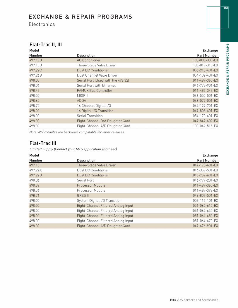
EX
CH
AN
GE
& R
EP
AIR
PR
OG
RA
MS
155
MTS 2015 Services and Accessories
EXCHANGE & REPAIR PROGRAMSElectronics
Flat-Trac II, IIIModel ExchangeNumber Description Part Number497.13B AC Conditioner 100-005-333-EX497.15B Three-Stage Valve Driver 100-019-313-EX497.22C Dual DC Conditioner 055-943-401-EX497.26B Dual Channel Valve Driver 054-102-401-EX498.05 Serial Port (Used with the 498.32) 011-487-360-EX498.06 Serial Port with Ethernet 046-778-901-EX498.47 PAMUX Bus Controller 011-487-343-EX498.55 MIOP II 046-555-501-EX498.65 ADDA 048-077-001-EX498.70 16 Channel Digital I/O 044-127-701-EX498.00 16 Digital I/O Transition 049-808-401-EX498.00 Serial Transition 054-170-601-EX498.00 Eight-Channel D/A Daughter Card 047-849-602-EX498.00 Eight-Channel A/D Daughter Card 100-042-515-EX
Note: 497 modules are backward compatable for letter releases.
Flat-Trac IIILimited Supply (Contact your MTS application engineer)
Model ExchangeNumber Description Part Number497.15 Three-Stage Valve Driver 047-178-601-EX497.22A Dual DC Conditioner 046-359-501-EX497.22B Dual DC Conditioner 048-757-601-EX498.06 Serial Port 046-779-201-EX498.32 Processor Module 011-487-365-EX498.36 Processor Module 011-487-392-EX498.71 GRES II 049-808-501-EX498.00 System Digital I/O Transition 053-112-101-EX498.00 Eight-Channel Filtered Analog Input 051-064-610-EX498.00 Eight-Channel Filtered Analog Input 051-064-630-EX498.00 Eight-Channel Filtered Analog Input 051-064-650-EX498.00 Eight-Channel Filtered Analog Input 051-064-670-EX498.00 Eight-Channel A/D Daughter Card 049-676-901-EX

EX
CH
AN
GE
& R
EP
AIR
PR
OG
RA
MS
156
MTS 2015 Services and Accessories
EXCHANGE & REPAIR PROGRAMSElectronics
RPC III Limited Supply (Contact your MTS application engineer)Model ExchangeNumber Description Part Number498.60 DCON 043-669-201-EX498.60B DCON 052-736-901-EX498.36 Processor Module 011-487-392-EX498.37 MJME 147SA-1 Processor 011-487-372-EX498.37 MJME 147-012 Processo 011-963-434-EX498.61 DSPAD 043-669-101-EX498.61B DSPAD 050-106-101-EX498.70 16 Channel Digital I/O 044-127-701-EX
FlexTest IIm, IIs, CTM & CTCLimited Supply (Contact your MTS application engineer)Model ExchangeNumber Description Part Number497.13B AC Conditioner 100-005-333-EX497.15B Three-Stage Valve Driver 100-019-313-EX497.22C Dual DC Conditioner 055-943-401-EX497.26B Dual Channel Valve Driver 054-102-401-EX498.34B Station Controller 100-048-996-EX497.36 FlexTest Communications 046-791-101-EX493.50 ADDA II 100-029-330-EX498.65 ADDA 048-077-001-EX498.70 16 Channel Digital I/O 044-127-701-EX498.71B GRES III 100-111-372-EX498.00 16 Digital I/O Transition 049-808-401-EX498.00 System Digital I/O Transition 053-112-101-EX498.00 Serial Transition 054-170-601-EX
FlexTest IIm, IIs, CTM & CTCLimited Supply (Contact your MTS application engineer)Model ExchangeNumber Description Part Number497.12 DC Conditioner 045-771-801-EX497.14 AC Conditioner 046-481-501-EX497.15A Three-Stage Valve Driver 047-178-601-EX497.22A Dual DC Conditioner 046-359-501-EX497.22B Dual DC Conditioner 048-757-601-EX497.26 Dual Channel Valve Driver 045-771-701-EX497.34A Station Controller 045-772-001-EX498.71 GRES II Transition Module 049-808-301-EX498.71 GRES II 049-808-501-EX498.71B GRES III 054-170-401-EX498.71C GRES III 100-111-372-EX498.00 Eight-Channel Filtered Analog Input 051-064-610-EX498.00 Eight-Channel Filtered Analog Input 051-064-630-EX498.00 Eight-Channel Filtered Analog Input 051-064-650-EX498.00 Eight-Channel Filtered Analog Input 051-064-670-EX498.00 Eight-Channel Filtered Analog Input (repair only) 051-064-690-EX498.00 Eight-Channel A/D Daughter Card 049-676-901-EX498.00 Eight-Channel A/D Daughter Card 100-042-515-EX498.00 Eight-Channel D/A Daughter Card 047-849-602-EX
Note: 497 modules are backward compatable for letter releases (A, B, C…).
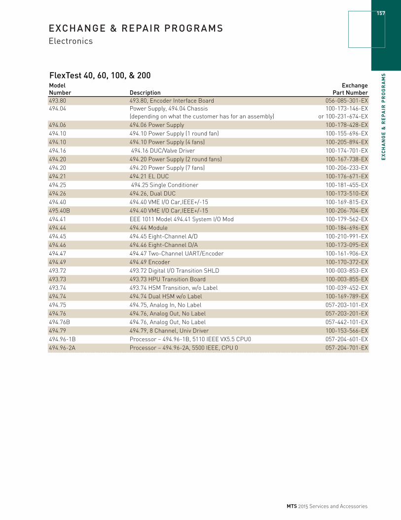
EX
CH
AN
GE
& R
EP
AIR
PR
OG
RA
MS
157
MTS 2015 Services and Accessories
EXCHANGE & REPAIR PROGRAMSElectronics
FlexTest 40, 60, 100, & 200Model ExchangeNumber Description Part Number493.80 493.80, Encoder Interface Board 056-085-301-EX494.04 Power Supply, 494.04 Chassis 100-173-146-EX
(depending on what the customer has for an assembly) or 100-231-674-EX494.06 494.06 Power Supply 100-178-428-EX494.10 494.10 Power Supply (1 round fan) 100-155-696-EX494.10 494.10 Power Supply (4 fans) 100-205-894-EX494.16 494.16 DUC/Valve Driver 100-174-701-EX494.20 494.20 Power Supply (2 round fans) 100-167-738-EX494.20 494.20 Power Supply (7 fans) 100-206-233-EX494.21 494.21 EL DUC 100-176-671-EX494.25 494.25 Single Conditioner 100-181-455-EX494.26 494.26, Dual DUC 100-173-510-EX494.40 494.40 VME I/O Car,IEEE+/-15 100-169-815-EX495.40B 494.40 VME I/O Car,IEEE+/-15 100-206-704-EX494.41 EEE 1011 Model 494.41 System I/O Mod 100-179-562-EX494.44 494.44 Module 100-184-696-EX494.45 494.45 Eight-Channel A/D 100-210-991-EX494.46 494.46 Eight-Channel D/A 100-173-095-EX494.47 494.47 Two-Channel UART/Encoder 100-161-906-EX494.49 494.49 Encoder 100-170-372-EX493.72 493.72 Digital I/O Transition SHLD 100-003-853-EX493.73 493.73 HPU Transition Board 100-003-855-EX493.74 493.74 HSM Transition, w/o Label 100-039-452-EX494.74 494.74 Dual HSM w/o Label 100-169-789-EX494.75 494.75, Analog In, No Label 057-203-101-EX494.76 494.76, Analog Out, No Label 057-203-201-EX494.76B 494.76, Analog Out, No Label 057-442-101-EX494.79 494.79, 8 Channel, Univ Driver 100-153-566-EX494.96-1B Processor – 494.96-1B, 5110 IEEE VX5.5 CPU0 057-204-601-EX494.96-2A Processor – 494.96-2A, 5500 IEEE, CPU 0 057-204-701-EX

EX
CH
AN
GE
& R
EP
AIR
PR
OG
RA
MS
158
MTS 2015 Services and Accessories
EXCHANGE & REPAIR PROGRAMSElectronics
FlexTest GTLimited Supply (Contact your MTS application engineer)
Model ExchangeNumber Description Part Number493.10* Chassis Assembly – (repair only)493.10 Power Supply Assembly – Lambda 100-031-143-EX493.14B Valve Driver for 252.x or 5x Valves 100-109-855-EX493.15B Three-Stage Valve Driver 100-109-974-EX493.20 493.20 Power Supply 100-031-183-EX493.21BC Digital Universal Conditioner 100-109-976-EX493.25B Digital Universal Conditioner 100-109-659-EX493.25C Digital Universal Conditioner 100-207-810-EX493.40 I/O Carrier Board 100-003-854-EX493.45 Analog Input Module – 6 Channel A/D 051-904-401-EX493.46 Analog Output Module – 6 Channel D/A 052-907-701-EX493.47 High Speed Encoder Module 055-351-501-EX493.48 Accelerometer Conditioner Module 100-011-578-EX493.71 RS485 100-003-832-EX493.72 Digital I/O Transition Module 100-003-853-EX493.73 HPU Transition Board 100-003-855-EX493.74 493.74 HSM Transition Station 1 & 2 100-039-452-EX493.75 Analog Input BNC Transition Module, 6 Channel 100-008-984-EX493.76 Analog Output BNC Transition Module, 6 100-008-986-EX493.77 Filter Input Transition Board, 6 Channel 300 HZ 056-013-705-EX493.78 Accelerated Input 100-013-651-EX498.71C Global resource III Module 100-111-372-EX
FlexTest SELimited Supply (Contact your MTS application engineer)
Model ExchangeNumber Description Part Number493.02 Chassis Assembly – Repair only 100-061-333-EX493.07 Hydraulic Interface Box 24 V 049-969-401-EX493.07 Hydraulic Interface Box 24 V (407 Controller Version) 049-969-402-EX493.07 Hydraulic Interface Box 115 V 049-969-403-EX493.07 Hydraulic Interface Box 115 V (407 Controller Version) 049-969-404-EX493.14 Two-Stage Valve Driver 048-934-001-EX493.14B Valve Driver for 252.x or 5x Valves 100-109-855-EX493.15 Three-Stage Valve Driver 053-782-701-EX493.15B Three-Stage Valve Driver 100-109-974-EX493.21B Digital Universal Conditioner 053-476-101-EX493.21BC Digital Universal Conditioner 100-109-976-EX493.25 Digital Universal Conditioner 100-033-468-EX493.25B Digital Universal Conditioner 100-109-659-EX493.25C Digital Universal Conditioner 100-207-810-EX493.40 I/O Carrier Board 100-003-854-EX493.42 I/O Module Assembly 100-056-617-EX493.45 Analog Input Module – 6 Channel A/D 051-904-401-EX493.46 Analog Output Module – 6 Channel D/A 052-907-701-EXNote: 493 modules are backward compatable for letter releases (A, B, C…), with the exception of the 493.21A.
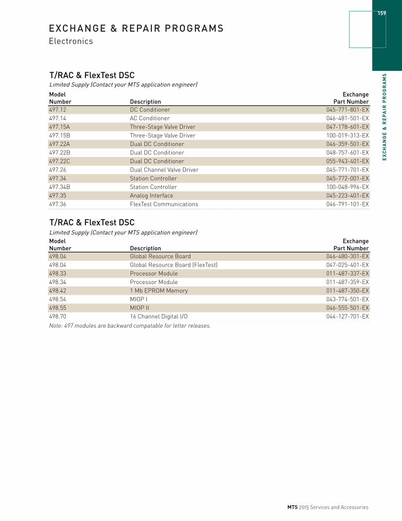
EX
CH
AN
GE
& R
EP
AIR
PR
OG
RA
MS
159
MTS 2015 Services and Accessories
EXCHANGE & REPAIR PROGRAMSElectronics
T/RAC & FlexTest DSCLimited Supply (Contact your MTS application engineer)
Model ExchangeNumber Description Part Number497.12 DC Conditioner 045-771-801-EX497.14 AC Conditioner 046-481-501-EX497.15A Three-Stage Valve Driver 047-178-601-EX497.15B Three-Stage Valve Driver 100-019-313-EX497.22A Dual DC Conditioner 046-359-501-EX497.22B Dual DC Conditioner 048-757-601-EX497.22C Dual DC Conditioner 055-943-401-EX497.26 Dual Channel Valve Driver 045-771-701-EX497.34 Station Controller 045-772-001-EX497.34B Station Controller 100-048-996-EX497.35 Analog Interface 045-223-401-EX497.36 FlexTest Communications 046-791-101-EX
T/RAC & FlexTest DSCLimited Supply (Contact your MTS application engineer)Model ExchangeNumber Description Part Number498.04 Global Resource Board 046-480-301-EX498.04 Global Resource Board (FlexTest) 047-025-401-EX498.33 Processor Module 011-487-337-EX498.34 Processor Module 011-487-359-EX498.42 1 Mb EPROM Memory 011-487-350-EX498.54 MIOP I 043-774-501-EX498.55 MIOP II 046-555-501-EX498.70 16 Channel Digital I/O 044-127-701-EX
Note: 497 modules are backward compatable for letter releases.

EX
CH
AN
GE
& R
EP
AIR
PR
OG
RA
MS
160
MTS 2015 Services and Accessories
EXCHANGE & REPAIR PROGRAMSOnsite Exchange Programs
The onsite exchange programs provide a cost-effective quick turnaround option to extend the life of your test equipment. You’ll receive a fully-warranted, remanufactured component to replace the worn component. A service contract and installation by MTS-trained personnel is required. The field service engineer will return the worn component to MTS as a core. This offer will be sold through a service contract. No core charge is needed or charged.
ADVANTAGES OF AN ONSITE EXCHANGE » Good-as-new performance for less than new
replacement cost.
» Latest product revision levels.
» Exchange components are remanufactured and tested to stringent standards.
» Minimizes downtime as this service may be scheduled with other onsite service activities.
» Extends the overall life of your test equipment.
» Saves labor and downtime costs by exchanging components instead of replacing equipment.
» Provides a perfect opportunity to add MTS Routine Maintenance and Fluid Assessment Services to monitor system performance moving forward. These services extend equipment life and help prevent untimely failures.
» Field delivery through MTS personnel only, eliminating your staff’s need to package the core for return.
Series 329 System Actuator Onsite ExchangeAvailable for 4DOF and 6DOF systems. Please consult your service sales representatives for more information.
CAPABILITYInclusion of a product in this catalog does not imply that it is mechanically or physically compatible with your existing equipment. Many MTS product configurations have been customized to meet specific system testing needs. Let us help you determine the compatibility required for an exchange.
HPU pump/motor module
329 system

EX
CH
AN
GE
& R
EP
AIR
PR
OG
RA
MS
161
MTS 2015 Services and Accessories
EXCHANGE & REPAIR PROGRAMSOnsite Exchange Programs
505.90 & 505.180 G1 SeriesHPU Series Voltage T.H/S.S. Pressure (psi) Exchange Part Number505.90 G1 380-480V T.H. 3000 057-492-601EX505.180 G1 380-480V T.H. 3000 057-492-602EX505.90 G1 380-480V S.S. 3000 057-492-603EX505.180 G1 380-480V S.S. 3000 057-492-604EX505.90 G1 575V T.H. 3000 057-492-605EX505.180 G1 575V T.H. 3000 057-492-606EX505.90 G1 575V S.S. 3000 057-492-607EX505.180 G1 575V S.S. 3000 057-492-608EX
505.07 G1 Series HPU Series Voltage T.H/S.S. Pressure (psi) Exchange Part Number505.07 G1 190/220-240V T.H. 3000 057-492-701EX505.07 G1 200-208V T.H. 3000 057-492-702EX505.07 G1 380-480V T.H. 3000 057-492-703EX505.07 G1 575V T.H. 3000 057-492-704EX505.07 G1 190/220-240V S.S./T.H. 3000 057-492-705EX505.07 G1 200-208V S.S./T.H. 3000 057-492-706EX505.07 G1 380-480V S.S./T.H. 3000 057-492-707EX505.07 G1 575V S.S./T.H. 3000 057-492-708EX
505.11 G1 Series HPU Series Voltage T.H/S.S. Pressure (psi) Exchange Part Number505.11 G1 190/220-240V T.H. 3000 057-492-801EX505.11 G1 200-208V T.H. 3000 057-492-802EX505.11 G1 380-480V T.H. 3000 057-492-803EX505.11 G1 575V T.H. 3000 057-492-804EX505.11 G1 190/220-240V S.S./T.H. 3000 057-492-805EX505.11 G1 200-208V S.S./T.H. 3000 057-492-806EX505.11 G1 380-480V S.S./T.H. 3000 057-492-807EX505.11 G1 575V S.S./T.H. 3000 057-492-808EX
505.20 G1 Series HPU Series Voltage T.H/S.S. Pressure (psi) Exchange Part Number505.20 G1 190/220-240V T.H. 3000 057-492-901EX505.20 G1 200-208V T.H. 3000 057-492-902EX505.20 G1 380-480V T.H. 3000 057-492-903EX505.20 G1 575V T.H. 3000 057-492-904EX
505.30 G1 SeriesHPU Series Voltage T.H/S.S. Pressure (psi) Exchange Part Number505.30 G1 190/220-240V S.S. 3000 057-493-001EX505.30 G1 200-208V S.S. 3000 057-493-002EX505.30 G1 380-480V S.S. 3000 057-493-003EX505.30 G1 575V S.S. 3000 057-493-004EX505.30 G1 200-208V T.H. 3000 057-493-006EX

EX
CH
AN
GE
& R
EP
AIR
PR
OG
RA
MS
162
MTS 2015 Services and Accessories
EXCHANGE & REPAIR PROGRAMSOnsite Exchange Programs
505.90 & 505.180 G2 Series HPU Series Voltage T.H/S.S. Pressure (psi) Exchange Part Number505.90 & 180 G2 380-480V T.H. 3000 057-492-601EX505.90 & 180 G2 380-480V S.S. 3000 057-492-603EX505.90 & 180 G2 575V T.H. 3000 057-492-605EX505.90 & 180 G2 575V S.S. 3000 057-492-607EX
505.07 G2 Series HPU Series Voltage T.H/S.S. Pressure (psi) Exchange Part Number505.07 G2 190/220-240V T.H. 3000 057-492-701EX505.07 G2 200-208V T.H. 3000 057-492-702EX505.07 G2 380-480V T.H. 3000 057-492-703EX505.07 G2 575V T.H. 3000 057-492-704EX505.07 G2 190/220-240V S.S./T.H. 3000 057-492-705EX505.07 G2 200-208V S.S./T.H. 3000 057-492-706EX505.07 G2 380-480V S.S./T.H. 3000 057-492-707EX505.07 G2 575V S.S./T.H. 3000 057-492-708EX
505.11 G2 Series HPU Series Voltage T.H/S.S. Pressure (psi) Exchange Part Number505.11 G2 190/220-240V T.H. 3000 057-492-801EX505.11 G2 200-208V T.H. 3000 057-492-802EX505.11 G2 380-480V T.H. 3000 057-492-803EX505.11 G2 575V T.H. 3000 057-492-804EX505.11 G2 190/220-240V S.S./T.H. 3000 057-492-805EX505.11 G2 200-208V S.S./T.H. 3000 057-492-806EX505.11 G2 380-480V S.S./T.H. 3000 057-492-807EX505.11 G2 575V S.S./T.H. 3000 057-492-808EX
505.20 G2 Series HPU Series Voltage T.H/S.S. Pressure (psi) Exchange Part Number505.20 G2 190/220-240V T.H. 3000 057-492-901EX505.20 G2 200-208V T.H. 3000 057-492-902EX505.20 G2 380-480V T.H. 3000 057-492-903EX505.20 G2 575V T.H. 3000 057-492-904EX
505.30 G2 SeriesHPU Series Voltage T.H/S.S. Pressure (psi) Exchange Part Number505.30 G2 190/220-240V S.S. 3000 057-493-001EX505.30 G2 200-208V S.S. 3000 057-493-002EX505.30 G12 380-480V S.S. 3000 057-493-003EX505.30 G2 575V S.S. 3000 057-493-004EX505.30 G2 200-208V T.H. 3000 057-493-006EX

EX
CH
AN
GE
& R
EP
AIR
PR
OG
RA
MS
163
MTS 2015 Services and Accessories
EXCHANGE & REPAIR PROGRAMSMTS Series 252 & 256 Servovalves
The MTS servovalve exchange program provides a cost effective, rapid turnaround replacement option for non-functioning servovalves. You can purchase a remanufactured, tested and fully-warranted product in exchange for your used unit to ensure top quality performance of your complete system.
FEATURES » Good-as-new performance for less than new product
replacement price
» Shipment within 24-hours (Monday-Friday)
» 12 Month Warranty
» Remanufactured to stringent MTS specifications using the latest product revision levels where applicable
» Convenient return shipping carton and label provided for easy return of the used servovalve core
COMPATIBILITY Inclusion of a product in this catalog does not imply that it is mechanically or physically compatible with your existing equipment. Many MTS product configurations have been customized to meet specific system testing needs. Let us help you determine the compatibility required for exchange or if functional replacement/upgrade is the best solution. MTS provides fit-form-function interchange exchange using the G-Type Model servovalves of the same 4 or 5 port configuration and flow size. The G-Type Model servovalves are completely interchangeable with the legacy C-Type Model servovalves.
EXCLUSIONSThe following types of exchanges are not supported/allowed:
» Exchange of 1970’s vintage Model A series servovalves
» Exchange of vintage 1980’s A-Series copper-body servovalves
» Change in 4 or 5 port configuration servovalves
» Change in servovalve flow size
» Exchange of Series 252.5x servovalves
» Exchange of high response (HR) servovalves
» Repair of A or C-Type Model servovalves. (C-Type servovalves can be Exchanged for G-Type)
How the valve exchange program works1. Contact the MTS Order Services Team to help you select
the proper remanufactured exchange valve. You will be asked to provide a secured payment method to cover the value of both the remanufactured valve and the value of your used core to be returned. Payment can be secured by one of the following methods.
» A purchase order
» A credit card
» An MTS service plan contract number
2. MTS will ship the remanufactured exchange valve that includes the used valve core return packaging.
3. Upon receiving the exchange valve, you must return your used valve core to MTS within 30 days of order placement.
4. Ship your used valve core back to MTS using the white inner carton provided. Ensure that the Return Authorization Number (RAN) is clearly indicated on the shipping labels and enclosed within the package.
5. When MTS receives your used valve core within 30 days of order placement, your final invoice will have only the exchange valve price.
6. When MTS does not receive your used valve core within 30 days of order placement or the used core is found to not qualify for remanufacture, your final invoice will have the exchange valve price plus the core value price as set in the initial purchase order.
NOTE FOR ALL EXCHANGESAll MTS remanufactured product exchanges require a core value to be associated with the purchase. Your purchase order must explicitly include both the exchange product price plus the core value. Please consult with your order services representative to answer any questions about exchange product and related core pricing. Upon returning your good condition and qualifying used core to MTS within 30 days of issuing the purchase order, MTS will not levy the core charge and you will pay for only the remanufactured exchange product.
FACTORY REPAIR SERVICE 256.XX1. Pilot
2. Basic cleaning/tunning/validation
3. Full rebuild

EX
CH
AN
GE
& R
EP
AIR
PR
OG
RA
MS
164
MTS 2015 Services and Accessories
EXCHANGE & REPAIR PROGRAMSMTS Series 252 Servovalves
Servovalves Models 252.2x - ExchangeModel ExchangeNumber Description Also Applies Part Number252.21G-01 1 gpm, 4 Port Servovalve 252.21C-01 056-006-101-EX
252.21G-04 1 gpm, 5 Port Servovalve 252.21C-04 056-006-104-EX
252.22G-01 2.5 gpm, 4 Port Servovalve 252.22C-01 056-006-201-EX
252.22G-04 2.5 gpm, 5 Port Servovalve 252.22C-04 056-006-204-EX
252.23G-01 5 gpm, 4 Port Servovalve 252.23C-01 056-006-301-EX
252.23G-04 5 gpm, 5 Port Servovalve 252.23C-04 056-006-304-EX
252.24G-01 10 gpm, 4 Port Servovalve 252.24C-01 056-006-401-EX
252.24G-04 10 gpm, 5 Port Servovalve 252.24C-04 056-006-404-EX
252.25G-01 15 gpm, 4 Port Servovalve 252.25C-01 056-006-501-EX
252.25G-04 15 gpm, 5 Port Servovalve 252.25C-04 056-006-504-EX
Servovalves Models 256.xx - Repair ServicesModel Number Description256.09 Pilot Contact MTS
256.09 Clean/Tunning/Validate Contact MTS
256.09 New Spool/Full Rebuild Contact MTS
256.18 Pilot Contact MTS
256.18 Clean/Tunning/Validate Contact MTS
256.18 New Spool/Full Rebuild Contact MTS
256.25 Pilot Contact MTS
256.25 Clean/Tunning/Validate Contact MTS
256.25 New Spool/Full Rebuild Contact MTS

RE
MA
NU
FA
CT
UR
E P
RO
GR
AM
S
165
MTS 2015 Services and Accessories
REMANUFACTURE PROGRAMSActuator
Model 204.xx
Model Number Rating204.08 1.1 kip No204.09 2.2 kip No204.11 2.5 kip No204.12 4.0 kip No204.13 6.0 kip No204.21 6.0 kip No204.22 9.0 kip No204.23 12 kip No204.24 20 kip No204.25 24 kip No204.26 35 kip No204.31 50 kip No204.32 70 kip No204.41 100 kip No204.42 150 kip No204.51 3.3 kip No204.52 5.5 kip No204.61 11 kip No204.62 15 kip No204.63 22 kip No204.64 35 kip No204.71 55 kip No204.72 77 kip No204.81 110 kip No204.82 165 kip No204.91 220 kip NoNote: These units are no longer in production; exact replacement of these units is not possible.MTS does carry functional replacements.
Model 231.xx to 248.xx
Model Number Rating231.xx No242.xx Yes244.11 3.3 kip Yes244.12 5.5 kip Yes244.20 15 kip Yes244.21 11 kip Yes244.22 22 kip Yes244.23 35 kip Yes244.31 55 kip Yes244.41 110 kip Yes244.51 220 kip Yes248.xx Contact MTS
Direct Replacement
New Production Actuators Still Available
Direct Replacement
New Production Actuators Still Available
RE
MA
NU
FA
CT
UR
E P
RO
GR
AM
S166
MTS 2015 Services and Accessories
REMANUFACTURE PROGRAMSActuator
Load Units with Integral Actuators
Model Number Rating318.10 3.3 kip Yes
318.10 5.5 kip Yes
318.10 11 kip Yes
318.10/25 22 kip Yes
318.25/50 55 kip Yes
318.50 110 kip Yes
Model 242.xx to 244.51 End Cap RemanufacturingModel Number Rating
242.xx
244.11 3.3 kip
244.12 5.5 kip
244.20* 15 kip
244.21* 11 kip
244.22 22 kip
244.23 35 kip
244.31 55 kip
244.41 110 kip
244.51 220 kip*Steel version only
Still Available New Production Actuators
Direct Replacement

MTS 2015 Services and Accessories
NOTES

CO
MP
AN
Y L
OC
AT
ION
S168
MTS 2015 Services and Accessories
COMPANY LOCATIONS
THE AMERICAS
MTS Systems Corporation14000 Technology DriveEden Prairie, MN 55344-2290USATelephone: 952-937-4000Toll Free: 800-328-2255Fax: 952-937-4515E-mail: [email protected]: www.mts.com
EUROPE
MTS Systems FranceBAT EXA 16 16/18 rue Eugène Dupuis94046 Créteil CedexFranceTelephone: +33-(0)1-58 43 90 00Fax: +33-(0)1-58 43 90 01E-mail: [email protected]
MTS Systems GmbHHohentwielsteig 314163 BerlinGermanyTelephone: +49-(0)30 81002-0Fax: +49-(0)30 81002-100E-mail: [email protected]
MTS Systems S.R.L. socio unicoStrada Pianezza 28910151 TorinoItalyTelephone: +39-(0)11 45175 11 sel. pass.Fax: +39-(0)11 45175 00 01E-mail: [email protected]
MTS Systems Norden AB Datavägen 37 SE-436 32 AskimSwedenTelephone: +46-(0)31-68 69 99Fax: +46-(0)31-68 69 8E-mail: [email protected]
MTS Systems Ltd. UKUnit 9, Cirencester Office ParkTetbury RoadCirencesterGloucestershire GL7 6JJUnited KingdomTelephone: +44-(0)1285-648800Fax: +44-(0)1285-658052E-mail: [email protected]
ASIA/PACIFIC
MTS Japan Ltd.ArcaCentral Bldg. 8F1-2-1 Kinshi, Sumida-kuTokyo 130-0013JapanTelephone: 81-3-6658-0901Fax: 81-3-6658-0904E-mail: [email protected]
MTS Korea, Inc.4th F., ATEC Tower, 289, Pankyo-ro, Bundang-gu Seongnam-si Gyeonggi-do 463-400, Korea Telephone: 82-31-728-1600 Fax: 82-31-728-1699 E-mail: [email protected]
MTS China Hechuan OfficeRoom 703 Building #B,Venture International Park,No. 2679 Hechuan Road,Minhang District,Shanghai 201103,P.R.ChinaTelephone: +86-21-5427 1122Fax: +86-21-6495 6330E-mail: [email protected]
Regional Business Centers Sales LocationsNORTH AMERICA
CanadaMontreal, QuebecToronto, OntarioWindsor, OntarioMexicoAguascalientesUnited States
CENTRAL AND SOUTH AMERICA
ArgentinaBuenos AiresBrazilSão PauloColombiaBogotaCosta RicaSan JoseVenezuelaCaracas
EUROPE
BulgariaSofiaCzech RepublicBrnoFranceLe ChesnayParisGermanyBerlinDelmenhorstEhingenNattheimRastattWendeburgGreeceAthensItalyTorinoNetherlandsGoudaPolandWarsawRomaniaBucharestRussiaMoscowSpainBarcelonaMadridSwedenGothenburgSwitzerlandHallauTurkeyIstanbulUkraineKievUnited KingdomNorthhamptonshireStroud, GlocesterSurrey
AFRICA AND THE MIDDLE EAST
EgyptHeliopolisIsraelTel AvivJordanAmmanMoroccoCasablancaSaudi ArabiaRiyadhSouth AfricaJohannesburgTunisiaTunisUnited Arab EmiratesDubai
ASIA/PACIFIC
Hong KongHong KongIndiaBangaloreChennaiCoimbatoreHaryana/PunjabMumbaiNew DelhiPuneTiruchyIndonesiaJakartaJapanNagoyaTokyoPeople’s Republic of ChinaBeijingChangchunChongqingGuangzhouShanghaiWuhanXi’anRepublic of KoreaDaejonSeoulSingaporeSingaporeTaiwanKaohsiungTaichungTaipei
AUSTRALIA AND NEW ZEALAND
AustraliaMelbourneSydney
TRAINING CENTERS
Americas Training CenterMTS Systems Corporation14000 Technology DriveEden Prairie, MN 55344-2290USATelephone: 952-937-4000Toll Free: 800-328-2255Fax: 952-937-4515E-mail: [email protected]: www.mts.com
Europe Training CenterMTS Systems GmbHHohentwielsteig 314163 BerlinGermanyTelephone: +49-(0)30 81002-222Fax: +49-(0)30 81002-100E-mail: [email protected]
Asia Training CenterMTS Korea, Inc.Sungkyunkwan Univ. Natural Sciences Campus: #83158 Research Complex 2, 300 Cheoncheon-dong Jangan-gu, Suwon-si,Gyeonggi-do 440-746 KoreaOffice Phone:+82-31-714-7151Fax: +82-31-714-7198E-mail: [email protected]
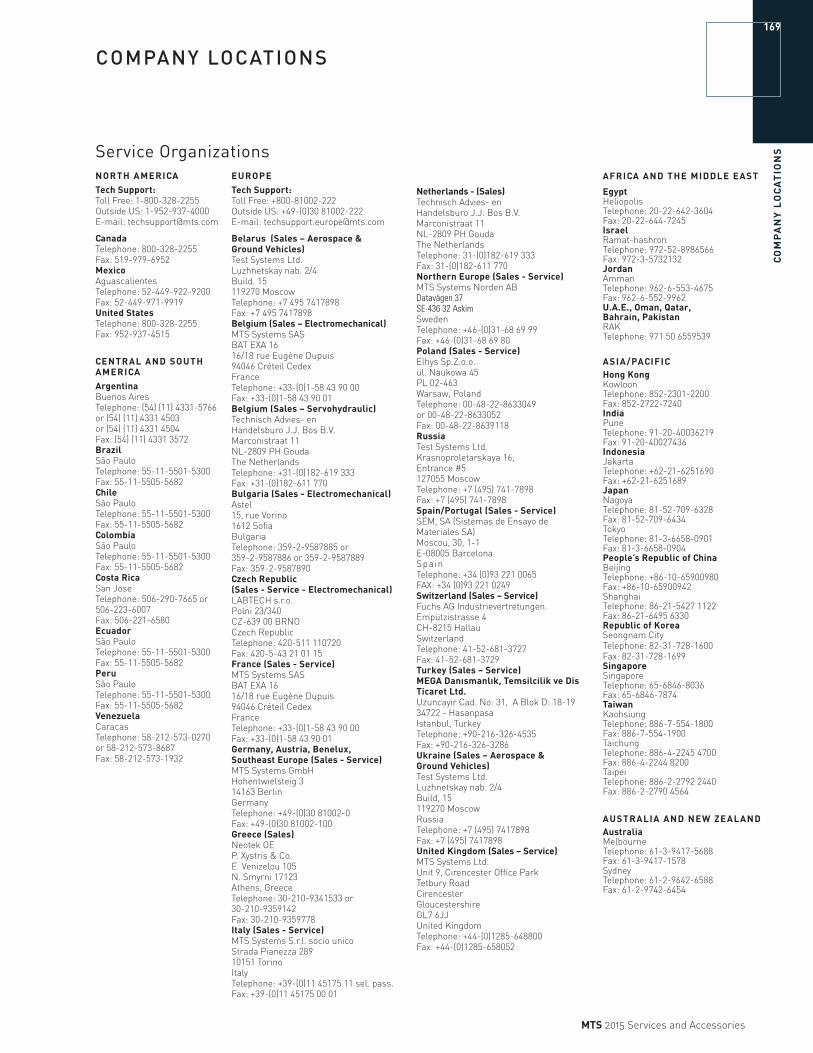
CO
MP
AN
Y L
OC
AT
ION
S
169
MTS 2015 Services and Accessories
COMPANY LOCATIONS
NORTH AMERICATech Support:Toll Free: 1-800-328-2255Outside US: 1-952-937-4000E-mail: [email protected]
CanadaTelephone: 800-328-2255Fax: 519-979-6952MexicoAguascalientesTelephone: 52-449-922-9200Fax: 52-449-971-9919United StatesTelephone: 800-328-2255Fax: 952-937-4515
CENTRAL AND SOUTH AMERICAArgentinaBuenos AiresTelephone: (54) (11) 4331-5766 or (54) (11) 4331 4503 or (54) (11) 4331 4504 Fax: (54) (11) 4331 3572BrazilSão PauloTelephone: 55-11-5501-5300Fax: 55-11-5505-5682ChileSão PauloTelephone: 55-11-5501-5300Fax: 55-11-5505-5682ColombiaSão PauloTelephone: 55-11-5501-5300Fax: 55-11-5505-5682Costa RicaSan JoseTelephone: 506-290-7665 or 506-223-6007Fax: 506-221-6580EcuadorSão PauloTelephone: 55-11-5501-5300Fax: 55-11-5505-5682PeruSão PauloTelephone: 55-11-5501-5300Fax: 55-11-5505-5682VenezuelaCaracasTelephone: 58-212-573-0270 or 58-212-573-8687Fax: 58-212-573-1932
EUROPETech Support:Toll Free: +800-81002-222Outside US: +49-(0)30 81002-222E-mail: [email protected]
Belarus (Sales – Aerospace & Ground Vehicles)Test Systems Ltd.Luzhnetskay nab. 2/4Build. 15119270 MoscowTelephone: +7 495 7417898Fax: +7 495 7417898Belgium (Sales – Electromechanical)MTS Systems SASBAT EXA 16 16/18 rue Eugène Dupuis94046 Créteil CedexFranceTelephone: +33-(0)1-58 43 90 00Fax: +33-(0)1-58 43 90 01Belgium (Sales – Servohydraulic)Technisch Advies- en Handelsburo J.J. Bos B.V.Marconistraat 11NL-2809 PH GoudaThe NetherlandsTelephone: +31-(0)182-619 333Fax: +31-(0)182-611 770 Bulgaria (Sales - Electromechanical)Astel15, rue Vorino1612 SofiaBulgaria Telephone: 359-2-9587885 or 359-2-9587886 or 359-2-9587889Fax: 359-2-9587890Czech Republic (Sales - Service - Electromechanical)LABTECH s.r.o.Polni 23/340CZ-639 00 BRNOCzech RepublicTelephone: 420-511 110720Fax: 420-5-43 21 01 15France (Sales - Service)MTS Systems SASBAT EXA 16 16/18 rue Eugène Dupuis94046 Créteil CedexFranceTelephone: +33-(0)1-58 43 90 00Fax: +33-(0)1-58 43 90 01Germany, Austria, Benelux, Southeast Europe (Sales - Service)MTS Systems GmbHHohentwielsteig 314163 BerlinGermanyTelephone: +49-(0)30 81002-0Fax: +49-(0)30 81002-100Greece (Sales)Neotek OE P. Xystris & Co.E. Venizelou 105N. Smyrni 17123Athens, GreeceTelephone: 30-210-9341533 or 30-210-9359142Fax: 30-210-9359778Italy (Sales - Service)MTS Systems S.r.l. socio unicoStrada Pianezza 289 10151 TorinoItalyTelephone: +39-(0)11 45175 11 sel. pass.Fax: +39-(0)11 45175 00 01
Service Organizations
Netherlands - (Sales)Technisch Advies- en Handelsburo J.J. Bos B.V.Marconistraat 11NL-2809 PH GoudaThe NetherlandsTelephone: 31-(0)182-619 333Fax: 31-(0)182-611 770Northern Europe (Sales - Service)MTS Systems Norden ABDatavägen 37 SE-436 32 AskimSwedenTelephone: +46-(0)31-68 69 99Fax: +46-(0)31-68 69 80Poland (Sales - Service)Elhys Sp.Z.o.o.ul. Naukowa 45PL 02-463 Warsaw, PolandTelephone: 00-48-22-8633049 or 00-48-22-8633052Fax: 00-48-22-8639118RussiaTest Systems Ltd.Krasnoproletarskaya 16,Entrance #5127055 MoscowTelephone: +7 (495) 741-7898Fax: +7 (495) 741-7898Spain/Portugal (Sales - Service) SEM, SA (Sistemas de Ensayo de Materiales SA)Moscou, 30, 1-1E-08005 BarcelonaSpainTelephone: +34 (0)93 221 0065FAX: +34 (0)93 221 0249Switzerland (Sales – Service)Fuchs AG Industrievertretungen.Empützistrasse 4CH-8215 HallauSwitzerlandTelephone: 41-52-681-3727Fax: 41-52-681-3729Turkey (Sales – Service) MEGA Danısmanlık, Temsilcilik ve Dis Ticaret Ltd.Uzuncayir Cad. No: 31, A Blok D: 18-1934722 - HasanpasaIstanbul, TurkeyTelephone: +90-216-326-4535Fax: +90-216-326-3286Ukraine (Sales – Aerospace & Ground Vehicles)Test Systems Ltd.Luzhnetskay nab. 2/4Build, 15119270 MoscowRussiaTelephone: +7 (495) 7417898Fax: +7 (495) 7417898United Kingdom (Sales – Service)MTS Systems Ltd.Unit 9, Cirencester Office ParkTetbury RoadCirencesterGloucestershireGL7 6JJ United Kingdom Telephone: +44-(0)1285-648800 Fax: +44-(0)1285-658052
AFRICA AND THE MIDDLE EAST
EgyptHeliopolisTelephone: 20-22-642-3604Fax: 20-22-644-7245IsraelRamat-hashronTelephone: 972-52-8986566Fax: 972-3-5732132JordanAmmanTelephone: 962-6-553-4675Fax: 962-6-552-9962U.A.E., Oman, Qatar, Bahrain, PakistanRAKTelephone: 971 50 6559539
ASIA/PACIFICHong KongKowloonTelephone: 852-2301-2200Fax: 852-2722-7240IndiaPuneTelephone: 91-20-40036219Fax: 91-20-40027436IndonesiaJakartaTelephone: +62-21-6251690Fax: +62-21-6251689JapanNagoyaTelephone: 81-52-709-6328Fax: 81-52-709-6434TokyoTelephone: 81-3-6658-0901Fax: 81-3-6658-0904People’s Republic of ChinaBeijingTelephone: +86-10-65900980Fax: +86-10-65900942ShanghaiTelephone: 86-21-5427 1122Fax: 86-21-6495 6330Republic of KoreaSeongnam CityTelephone: 82-31-728-1600 Fax: 82-31-728-1699SingaporeSingaporeTelephone: 65-6846-8036Fax: 65-6846-7874TaiwanKaohsiungTelephone: 886-7-554-1800Fax: 886-7-554-1900TaichungTelephone: 886-4-2245 4700Fax: 886-4-2244 8200TaipeiTelephone: 886-2-2792 2440 Fax: 886-2-2790 4564
AUSTRALIA AND NEW ZEALANDAustraliaMelbourneTelephone: 61-3-9417-5688Fax: 61-3-9417-1578SydneyTelephone: 61-2-9642-6588Fax: 61-2-9742-6454

Services & Accessories
mMTS Systems Corporation14000 Technology DriveEden Prairie, Minnesota 55344-2290 USAToll Free: 800·328·2255Telephone: 952·937·4000 Fax: 952·937·4515E-mail: [email protected]://www.mts.com
ISO 9001 CERTIFIED QMS
©2015 MTS Systems Corporation100-299-144 English Printed in U.S.A. 1/15
MTS, Bionix, Flat-Trac, FlexTest, MTS EM Extend, MTS Insight, RPC, SWIFT, TestWare, and TestWorks are registered trademarks; Advantage, Aero-90, Elastomer Express, Just In Case, MAST, MicroProfiler, MTS Fundamental, SilentFlo, TestStar, MTS Landmark and T/RAC are trademarks of MTS Systems Corporation within the United States. These trademarks may be protected in other countries.
Android is a trademark of Google Inc.
Apple is a registered trademark of Apple, Inc., registered in the U.S. and other countries.iOS is a registered trademark of Cisco Systems, Inc.
Products or company names other than trademarks of MTS Systems Corporation are used for identification purposes only and may be trademarks of their respective owners.
All specifications are subject to change without notice. Please contact MTS for specifications critical to your application. MTS reserves the right to change products, services and prices without notice.
Introduction
Services
Load Cells
Extensometers
Grips & Fixtures
Furnace & Chambers
Testing System Components
Additional Components
MTS Maintenance Parts
Exchange & Repair Programs
Remanufacture Programs
Company Locations