multi-modal intelligent traffic signal system (mmitss ... · the mmitss-ca is designed as addon...
TRANSCRIPT

1
Multi-Modal Intelligent Traffic Signal System (MMITSS) Phase III: Development Plan
June 19, 2019
University of Arizona (Lead)
University of California PATH Program

2
Table of Contents
1 Background .................................................................................................................... 4
2 Needs Analysis ............................................................................................................... 5 2.1 MMITSS Gap Analysis ..........................................................................................................6 2.2 MMITSS Development Group Meeting .................................................................................6 2.3 Summary of MMITSS Enhancements ....................................................................................8
3 MMITSS Enhancements ................................................................................................ 10
4 Prioritization of the MMITSS Enhancements ................................................................. 32
5 Enhancement of Existing MMITSS Prototypes ............................................................... 36
6 Prioritized Enhancements for MMITSS Phase 4 ............................................................. 39
APPENDIX A. Open Source Repository Collaboration Process ............................................... 40 MMITSS Team Collaboration, Common Components, and Shared Libraries ..................................... 40 Open Source Collaboration ................................................................................................................. 41
APPENDIX B. FHWA GAP ANALYSIS REPORT ......................................................................... 44
APPENDIX C. MMITSS Development Group Roster ............................................................... 51

3
Table of Figures
FIGURE 1. MDG MEETING IDENTIFIED PRIORITIES. ................................................................................................................... 6 FIGURE 2. MMITSS USABILITY USE CASES. .......................................................................................................................... 28 FIGURE 3. COMMON MMITSS LIBRARIES/COMPONENTS. ....................................................................................................... 36 FIGURE 4. MMITSS DEVELOPMENT PLAN............................................................................................................................ 38 FIGURE 5. PRIVATE (LEFT) AND PUBLIC (RIGHT) GITHUB REPOSITORIES. ...................................................................................... 40 FIGURE 6. REPOSITORY ISSUE TRACKING. .............................................................................................................................. 40 FIGURE 7. GITHUB BRANCHES. ............................................................................................................................................ 41 FIGURE 8. USDOT OSADP. .............................................................................................................................................. 42 FIGURE 9. MMITSS ORGANIZATION ON GITHUB. .................................................................................................................. 43
List of Tables
TABLE 1. SUMMARY OF MMITSS ENHANCEMENTS. ................................................................................................................. 8 TABLE 2. MMITSS REQUIRED BSM DATA ELEMENTS. ............................................................................................................ 13 TABLE 3. MMITSS REQUIRED SRM DATA ELEMENTS. ............................................................................................................ 14 TABLE 4. MMITSS REQUIRED MAP DATA ELEMENTS. ........................................................................................................... 14 TABLE 5. MMITSS REQUIRED SPAT DATA ELEMENTS............................................................................................................. 15 TABLE 6. MMITSS REQUIRED SSM DATA ELEMENTS. ............................................................................................................ 15 TABLE 7. COMPARISON OF MMITSS .NMAP FILE WITH SAE J2736-201603 MAP FOR TRANSMISSION.......................................... 17 TABLE 8. RANKED BY AND WITHIN CATEGORIES. ..................................................................................................................... 33 TABLE 9. MMITSS ENHANCEMENTS FOR PHASE IV (PROPOSED). .............................................................................................. 39

4
1 Background The Connected Vehicle Pooled Fund Study (CV PFS) identified the need to enhance the deployability of the Multi-Modal Intelligent Traffic Signal System (MMITSS) prototypes to address needs identified by the Pooled Fund Members, stakeholders, and the MMITSS developers, which include University of Arizona and California Partners for Advanced Transportation Technology (PATH) programs.
The goal of this Phase III effort is to make deployment readiness enhancements to the MMITSS prototypes that were developed and field tested in Phase II. The readiness enhancements are focused on creating enhanced and “cleaned up”, or mature, application code that is hardware agnostic and interoperable or transferable regardless of the hardware vendors or products. To achieve these goals, the project team identified the following enhancements:
• Improve the MMITSS software manuals, including the requirements on the host platforms and compilers, the download and build instructions, software design documentation, and a specification of an Application Programming Interface (API) for the Roadside Unit (RSU) Dedicated Short Range Communication (DSRC) interface that vendors can implement to support interoperability.
• Increase the source code maturity through code reviews with the MMITSS Development Group of stakeholders, including changes that make the source code hardware agnostic.
• Identify enhancements required for deployability, including upgrading to the 2016 Society of Automotive Engineers (SAE) J2735 message set, and field testing of traffic control enhancements including coordination for both MMITSS-Arizona (AZ) and MMITSS-California (CA).
• Carry out additional development of essential functions for MMITSS through field testing for improvements and fine tuning.
The MMITSS Phase II effort resulted in two distinctly different prototype systems that were field tested. The two systems have functions that are designed to work with two types of traffic control schemes. The MMITSS-AZ incorporates MMITSS with an adaptive traffic signal control algorithm. The MMITSS-CA is designed as add-on MMITSS features that complement the existing actuated-coordinated traffic signal control.
The MMITSS-AZ system is based on the development of new traffic control algorithms that use connected vehicle data to be adaptive and to serve multiple active priority requests. MMITSS-AZ utilizes the National Transportation Communications for Intelligent Transportation System Protocols (NTCIP 1202 v2 and 1211) when communicating with the traffic signal controller. MMITSS-AZ was field tested using Savari RSUs; hence the software utilizes Savari Linux libraries. MMITSS-AZ was also developed to run on standard Linux (Ubuntu 14.04) for use in simulation testing. The component-based architecture allows many of the components to be run on a Linux-based roadside processor, called the MMITSS Roadside Processor in the MMITSS architecture. This alternative deployment has been demonstrated using the Econolite Connected Vehicle CoProcessor (CVCP) board that is a field hardened Linux board.

5
The MMITSS-CA system is based on improving the existing actuated-coordinated traffic control system, with performance enhancements that utilize connected vehicle data, and providing dynamic priority control that serves multiple active priority requests and considers the prevailing traffic conditions. For example, signal priority and traffic coordination are achieved using the Caltrans 2070 firmware, but the decisions to call priority (with desired green splits for the priority cycles) or to modify a coordination parameter (splits, cycle length, or offset) are made based on data from connected vehicles that allow the MMITSS-CA system to decide the best control strategies. MMITSS-CA utilizes the AB3418 serial communications protocol from a Linux MMITSS Roadside Processor (MRP) to the traffic signal controller. The MMITSS-CA system utilizes a data manager, hosted by the MRP, to collect and distribute information to the other MRP software components. The MMITSS-CA team plans to add interface functions for priority and traffic control supporting NTCIP controllers as part of this deployment readiness project.
The MMITSS team has investigated options for integrating the two MMITSS prototypes into a single MMITSS that has options, such as the use of NTCIP or AB3418, use of actuated-coordinated traffic signal control mode from MMITSS-CA, and the adaptive signal control algorithms from MMITSS-AZ. The team determined that traffic control agencies will use either the actuated-coordinated control mode or the adaptive but not both simultaneously; hence there is no need to switch between the two MMITSS schemes. Due to the significant differences in the algorithms and the prototype software, it has been determined that this integration effort would distract, and consume available resources, from the Phase III effort to improve the deployment readiness of each system. There are opportunities, such as in the definition of the interfaces between MMITSS components that could be harmonized so that it may be possible to mix and match some of the components in the future. This is discussed further in Section 1. The team will continue to work simultaneously on two MMITSS prototypes: MMITSS-AZ and MMITSS-CA, and that agencies that choose to adopt MMITSS can consider the individual of merits of each system that best meets their needs. Where the interfaces can be harmonized there are opportunities for further integration.
2 Needs Analysis This section summarizes the MMITSS development needs that have been identified in the MMITSS Phase III RFP and Proposal, the Arizona/PATH team, through the FHWA Gap Analysis, and the MMITSS Development Group (MDG) meeting. After brief review of the MMITSS Gap Analysis and MDG meeting findings, a summary of the results is presented. This summary was presented at the Pooled Fund meeting in Atlanta on December 4, 2018 where participants were asked to rank the importance of each development item. The results of the ranking were summarized to create a list of improvements to MMITSS that will be used to guide the current and future development efforts.

6
2.1 MMITSS Gap Analysis The Federal Highway Administration (FHWA) conducted a MMITSS Gap Analysis1 to determine the needs of MMITSS that could be addressed to support widescale deployment. The Gap Analysis included a review of the MMITSS Concept of Operations, review of the current MMITSS prototypes, and discussion with key stakeholders. The analysis found that most of the current needs were being address through existing project and were focused on making the system readily deployable. The improvements included improved interface with the traffic signal controller, extending the DSRC range and developing a generic software application. As such, the Gap Analysis found that new research should focus on traffic management at the freeway and arterial interface, including ramp metering and adaptive signal control as well as integrating with other connected vehicle applications such as Integrated Network Flow Optimization (INFLO). In addition, new research should address some of the deferred use cases including congestion control, nearside bus stops, rail crossings, equipped bicycles, weather impacts, and route-based priority/preemption. In addition, there was a need to coordinate with other deployers/standard groups including Crash Avoidance Metrics Partnership (CAMP) and the Original Equipment Manufacturers (OEM). The findings from the GAP Analysis were used in development of the new traffic control features identified in the MMITSS Phase III scope of work and proposal.
2.2 MMITSS Development Group Meeting The MMITSS Development Group (MDG) was initiated with a two-day kick-off meeting on May 2-3, 2018 at the Turner-Fairbank Highway Research Center (TFHRC) in McLean, VA. The MDG includes members of the CV Pooled Fund, systems integrators and consultants working in CV applications, controller manufacturers, CV equipment manufacturers, and agency champions. The MDG meeting included detailed presentations of the MMITSS prototypes, code reviews, needs identification and prioritization activities. The MMITSS research team provided technical support and answers to questions regarding the build process, integration, host platform (e.g. Linux Ubuntu 14.04), standards, source code review (plans) and other topics identified by the MDG members. The MDG Roster is attached as APPENDIX C. MMITSS Development Group Roster of this document.
1 A High-Level Gap Analysis of Enhancing Current CV Arterial Coordination (MMITSS), July 7, 2016, provided in email by Gene McHale. [A copy of this report is included in Appendix B.]
Figure 1. MDG Meeting Identified Priorities.

7
At the end of the kick-off meeting, a prioritized list of development needs was identified. The needs were classified into groups, prioritized, and used to develop the contents of this MMITSS Development Plan. Figure 1 shows a picture of the list identified by the MDG members at the meeting. This input has been included in the analysis presented in Section 4. The list includes:
• Architecture – code base o Improve maintainability of the code o Security o Build script o Create common lib(rary) o Test cases o Persistant configuration data storage o Messages and required fields
• Usability o Visualization o Enable-disable feature o Alerts
• Traffic control features o Demonstration of o Effectiveness of o Coordination/coordination+priority
• Doculentation o Code o Users Manual
• Marketing • Licensing
The items on this list are includes in the summary of enhancements discussed in Section 2.3.
The MDG activities will be conducted as a webinar after this development plan is approved and accepted. A webinar format where source code walkthroughs and reviews will be conducted monthly, or as needed, as part of the effort to “clean up” the code and make it more usable by the MDG stakeholders who are engaged in deploying the code. The sequence of source code reviews will be based on the preference of the MDG stakeholders and the logical steps defined in the plan.
A regular, quarterly, update schedule will be developed to ensure that the MDG members have access to the current version of MMITSS source code. At a minimum, the Open Source Application Development Portal (OSADP) distribution will be updated quarterly. As members of the MDG identify additional issues or needs, the group can hold virtual meetings to discuss solutions, needs, priorities, and development schedules. These virtual meetings will be offered quarterly, or more frequently, as needed.

8
2.3 Summary of MMITSS Enhancements The MMITSS enhancements have been assigned numbers according to a work breakdown structure (WBS) as shown in Table 1. Needs are grouped into categories numbered 1.00, 2.00, etc. Each need is identified with a brief description. The source of the need is identified as: RFP/Proposal, UA/PATH Team, FHWA Gap Analysis, and MMITSS Development Group (MDG) and the table is labeled to indicate of the need is required in the RFP/Proposal (‘R’) or identified as a desired enhancement (‘X’).
Table 1. Summary of MMITSS Enhancements.
Item Number Brief Description
Source
RFP/Proposal UA/PATH Team
FHWA Gap Analysis MDG
1.00 Improve the software source code and documentation, including the maturity of the code, build scripts, and software and user documentation.
R X X X
1.01 Improve maturity of the code R X X X
1.02 Improve documentation R X X X
1.03 Add build scripts R X X
1.04 Development of a common component interface X X
1.05 Develop a NTCIP interface for MMITSS-CA R X
2.00 Upgrade to the 2016 SAE J2735 standard. R X X
2.01 Development of a common J2735 Library R X X
2.02 Development of a common MAP Engine X X X
3.00 Development of an API to the RSU 4.1 Standard Specification R X
4.00 Update the System Performance Measures R X
5.00 Develop an interface to the US DOT ITS Public Data Hub R X
6.00 Improve software testing environment X X
6.01 Create Unit Test Cases X X
6.02 Upgrade virtual-MMITSS simulation X X
6.02.01 Update the VISSIM Drivermodel.dll
6.02.02 Update the Docker Containers
7.00 Improving the approach to configuration data storage (persistence)
X X
7.01 Improve Interface for Data Configuration X
8.00 Enhancing traffic control features X X
8.01 Integration of coordination and priority control R X X X
8.02 Section level priority control R X
8.03 Congestion Control X
8.04 Near-side Bus Stop X
8.05 Left Turn Priority X

9
8.06 Railroad Crossings X
8.07 Equipped Bicyclist X
8.08 Weather considerations for non-motorized travelers X
8.09 Route-based preemption/priority X
8.10 N-Level Priority Policy X
8.11 Vehicle Dynamics in Priority Requests X
8.12 Queue Dynamics X
8.13 Advanced Freeway Ramp Metering and Priority X
8.14 Enhancement of the PED-SIG App X
9.00 Demonstration of the effectiveness of the traffic control features
X
10.00 Improving the usability X X
10.01 Add enable/disable feature X X
10.02 Add Alerts X X
10.03 Add Visualization X X
11.00 Integration/implementation of security protocols (IEEE 1609.2)
X
12.00 Develop an API to the On-Board Unit (OBU) X X
13.00 Extend Communicaiton Range (beyond DSRC using alterative technologies)
X X
14.00 Integration with other CV Applications X
15.00 Marketing X
16.00 Licensing X
17.00 Field Testing X X 17.01 90-day Operational Test R X 17.02 Testing with higher market penetration X X
17.03 Operational Performance Measures (e.g. availability, reliability, message count, …) R X
17.04 Additional CV Performance Measures X X
There is no specific order to these identified enhancements, but there is a logical development order for some of the specific enhancements. For example, in order to support mature development, the software test environment (6.00) needs to be improved. Improving the approach to configuration data storage (7.00) (and access) will contribute to improving the usability. Enhancing the traffic control features (8.00) and demonstrating the effectiveness of these features (9.00), will help agencies determine if MMITSS is a desirable traffic control solution. Usability (10.00) of MMITSS is an important enhancement that will allow users to better understand and apply MMITSS as a traffic management tool. Implementation of the security protocols (11.00), including message signing and message validation, are required if general vehicles will eventually participate in the use of the system. Each of these enhancements, including the specific items in each category (e.g. 8.01 – integration coordination and priority) are discussed below.

10
3 MMITSS Enhancements The MMITSS prototypes represent the results of a research and development effort focused on a new approach to traffic control that utilizes information from connected vehicles, especially passenger vehicles, emergency vehicles, transit, trucks, and pedestrians. The prototypes were developed to the level of maturity required to support field testing, proof-of-concept, and demonstrations. It is acknowledged that they are not ready for wide-scale deployment and additional development is needed to ensure that they have greater utility to the projects planning to use them and to the future of traffic control.
This section provides a brief description of each of the enhancements identified in Table 1. Some of the items are described in more detail than others based on the work completed prior to the development of this development plan.
1.00 Improve the software source code and documentation
The first group captures the need for overall improvement in the software quality including maturity of the code, software documentation, build scripts, and user documentation.
Both the MMITSS-AZ and MMITSS-CA source code, software build manual, installation manual, and software design documentation were developed in the MMITSS Phase II effort that focused on algorithm development and field demonstration. The software source code and documentation are of prototype quality. There is a need to improve the quality and maturity of the code, improve the documentation, and add build scripts so that other development teams can adopt the code and be assured that it will build according to the define development environment.
1.01 Improve the maturity of the code
The maturity of the source code will be improved through a series of software reviews, refactoring, review, development, unit testing and integration testing. To ensure the quality improves, the MMITSS Development Group will be engaged to participate in code reviews. The source code will be posted on a public GitHub repository so that the community can have access and participate as contributors if desired.
1.02 Improve Documentation
Both the software and the user documentation need to be improved to provide better description of the software design, build, and deployment processes. The user documentation needs to capture the key use cases and provide guidance for new users, and experienced users, to operate MMITSS. The software documentation needs to capture the design, implementation, and build processes for software development. Additionally, the original (Phase I) MMITSS documentation, including the Concept of Operations, System Requirements, and High Level Design documents, needs to be updated to reflect the current status of MMITSS.

11
1.03 Add Build Scripts
The open source software is complex and is based on many different source code files and results in several software components when it is built. The build scripts need to be part of the open source distribution so that adopters can easily build the software. The build scripts need to be developed to ensure no hard-coded paths are included so that adopters can choose the build location independent of the MMITSS Team decisions, but recognizing the inherent organization of MMITSS components.
1.04 Develop Common Component Interface
Currently, the MMITSS-AZ and MMITSS-CA prototypes both used sockets to allow the software components to communicate with each other. The two prototypes are based on slightly different architectures, but they are both based on the concept of components sharing data to accomplish the desired traffic control algorithms. The MMITSS-CA prototype uses a common data manager component where all data is available to any component at any time. The MMITSS-AZ prototype assumes that any component can communicate with any other component to get or provide data when it is needed. While architecturally different, they both use the approach of getting and providing data between components.
An approach has been adopted to develop a common communication approach (sockets) with serialized communications and a common set of data objects that will allow any of the MMITSS-AZ components to communicate with MMITSS-CA components and vice versa. Serialization is the process of packing the data in an object (or data structure) into a bit stream that can be transmitted over a communications network. This same mechanism can be used if software components are run on the same computer or on different computers (distributed).
Currently, MMITSS-AZ uses sockets with data elements defined based on the J2735 (2009) messages and data elements with additional data elements defined as needed. Serialization is done using an ASN.1 encoding approach or manually packing messages into the bit stream. MMITSS-CA uses internally defined data objects (structures) and manually packing of the bit stream. Harmonizing the data objects (elements) and using an open source serialization library, such as Boost2 serialization libraries, will theoretically allow the different components to interoperate. It should be noted that the two prototypes use some different data objects, such as the MMITSS-AZ vehicle trajectories, that might not allow complete integration, but this harmonization and common approach will allow some level of integration and some future integration as desired.
An alternative approach would be to use a platform such as the V2X-Hub being developed by the FHWA. As of the development of this report, the V2X-Hub isn’t shared as open source software, but could replace the common component interface in the future.
2 Boost Serialization Library, https://www.boost.org/doc/libs/1_68_0/libs/serialization/doc/index.html

12
To address this need, each team (MMITSS AZ and MMITSS CA) will develop a list of the data elements that are shared between the different components. The two lists will be reviewed to identify common and unique data elements. It is assumed that some of the common elements may have to be modified to meet the needs of both systems. Given the list of common elements, at interface will be defined that will be common to all MMITSS components. A socket and serialization package, e.g. Boost, will be used to create the common interface. Before selecting the package to be used, development testing will be done to ensure that the interface is buildable in both the MMITSS Roadside processor (Linux) and on the specific vendor OBU devices (e.g. Savari, Cohda, …).
1.05 Develop NCTIP interface for MMITSS-CA
MMITSS-CA uses the AB3418E protocol to communicate with the Caltrans 2070 controller software. To allow the MMITSS-CA algorithms to be used with other controllers, the MMITSS-CA team will develop an NTCIP interface that can communicate with modern traffic signal controllers that utilize the NTCIP 1202 objects.
2.00 Upgrade to the 2016 J2735 standard
The second group addresses the need to upgrade to the 2016 version of the SAE J2735 message library standard.
There are two efforts needed to support the 2016 J2735 standard. A common 2016 J2735 message library and a MAP engine/library is needed that will encapsulate the 2016 J2735 standard. In the future, any updates to the standard will be localized to these two libraries so that the other MMITSS software can be maintained and won’t require changes to accommodate updates to the standard.
2.01 Development of a common J2735 library
The Phase II effort utilized the SAE J2735 2009 standard and the MMITSS team participated in making improvements to the standard to support the MMITSS operation. There are significant changes to the 2016 version of the standard including a new message frame for every message, a new MAP message specification, a new SSM that is based on the MMITSS Phase II priority use case, and the use of Unaligned Packed Encoding Rules (UPER) encoding of the message payload. The MAP message is used in several MMITSS components to determine if a vehicle is in the roadway or off the roadway, such as in an adjacent parking lot. Hence, changing the MAP representation and functions in MMITSS is a significant change.
The approach adopted to address this need includes development of a common SAE J2735 Message Library for MMITSS. This Library should be able to compile and run at both MRP and OBU. The goal of this Library is for encoding and decoding MMITSS relevant SAE J2735-201603 messages, including BSM, SRM, MAP, SPaT, and SSM, and relevant Radio Technical Commission for Maritime Services (RTCM) Corrections messages. When needed, this Library will

13
expand to include encoding and decoding of Roadside Alert, Working Zone Alert, and Intersection Situation Data (ISD) messages to data warehouse.
The development of the SAE J2735 Message Library will take the existing MMITSS-CA J2735-201603 Message Library as the starting point, which utilizes the open source ASN.1 C-compiler (https://github.com/vlm/asn1c) for UPER encoding and decoding, and has been validated with United States Department of Transportation (USDOT) Connected Vehicle Message Validator (https://webapp2.connectedvcs.com/validator/).
To reduce the reliance and the needs for re-development of MMITSS due to the changes of SAE J2735 messages in the future, the MMITSS team will define the internal data structures used as inputs for message encoding and outputs for message decoding, therefore, the software modules that consume the over-the-air messages can be independent of SAE J2735 message definition. Transmitting the internal structured data will follow the same Common Component Interface (socket and data serialization) as described in 1.04.
ASN.1 definition for MMITSS relevant SAE J2735 messages includes Required and Optional Data Frames (DF) and Data Elements (DE). Some of the optional DFs and/or DEs are required to support MMITSS applications. The MMITSS team will identify the necessary Optional data for transmission. Table 2 to Table 6 below list the required data elements for MMITSS relevant SAE J2735 messages. The “Purpose to Include” column lists the consideration of including the corresponding data element as a Required data element.
Table 2. MMITSS Required BSM Data Elements.
SAE J2735-201603 MMITSS Implementation Purpose to IncludecoreData BSMcoreData (DF) Required RequiredpartII PartIIcontent (DF) Optional Optional
MSG_BasicSafetyMessage (BSM)

14
Table 3. MMITSS Required SRM Data Elements.
Table 4. MMITSS Required MAP Data Elements.
SAE J2735-201603 MMITSS Implementation Purpose to IncludetimeStamp MinuteOfTheYear (DE) Optional Optionalsecond DSecond (DE) Required RequiredsequenceNumber MsgCount (DE) Optional Required For identifying updated SRMrequests SignalRequestList (DF) Optional Required For priority control
SignalRequestPackage (DF)request SignalRequest (DF) Required Required
id IntersectionReferenceID (DF) Required Requiredregion RoadRegulatorID (DE) Optional Required For compatibility across regionsid IntersectionID (DE) Required Required
requestID RequestID (DE) Required RequiredrequestType PriorityRequestType (DE) Required RequiredinBoundLane IntersectionAccessPoint (DF) Required Required Choice of LaneID or ApproachIDoutBoundLane IntersectionAccessPoint (DF) Optional Optional Better to have (for priority control)
minute MinuteOfTheYear (DE) Optional Optionalsecond DSecond (DE) Optional Optionalduration DSecond (DE) Optional Optional
requestor RequestorDescription (DF) Required Requiredid VehicleID (DE) Required Required BSM TemporaryIDtype RequestorType (DF) Optional Required For multi-modal priority control
role BasicVehicleRole (DE) Required Requiredsubrole RequestSubRole (DE) Optional Optionalrequest RequestImportanceLevel (DE) Optional Required For N-level priority controliso3883 Iso3833VehicleType (DE) Optional OptionalhpmsType VehicleType (DE) Optional Required For multi-modal priority control
position RequestorPositionVector (DF) Optional Requiredposition Position3D (DF) Required Requiredheading Angle (DE) Optional Requiredspeed TransmissionAndSpeed (DF) Optional Required
name DescriptiveName (DE) Optional OptionalrouteName DescriptiveName (DE) Optional OptionaltransitStatus TransitVehicleStatus (DE) Optional OptionaltransitOccupancy TransitVehicleOccupancy (DE) Optional OptionaltransitSchedule DeltaTime (DE) Optional Optional
MSG_SignalRequestMessage (SRM)
The MRP could estimate the service time and duration by combining SRM with BSM
Part of BSM
It is OBU's responsibility to determine the level of priority to request.
SAE J2735-201603 MMITSS Implementation Purpose to IncludemsgIssueRevision MsgCount (DE) Required RequiredlayerType LayerType (DE) Optional Required Specify this is intersectionDataintersections IntersectionGeometryList (DF) Optional Required
IntersectionGeometry (DF)id IntersectionReferenceID (DF) Required Required
region RoadRegulatorID (DE) Optional Required For compatibility across regionsid IntersectionID (DE) Required Required
revision MsgCount (DE) Required RequiredrefPoint Position3D (DF) Required Required
lat Latitude (DE) Required Requiredlong Longitude (DE) Required Required
laneWidth LaneWidth (DE) Optional Required For geo-fencingspeedLimits SpeedLimitList (DF) Optional Required Specify regulatory speed limitlaneSet LaneList (DF) Required Required
GenericLane (DF)laneID LaneID (DE) Required RequiredingressApproach ApproachID (DE) Optional RequiredegressApproach ApproachID (DE) Optional RequiredlaneAttributes LaneAttributes (DF) Required Requiredmaneuvers AllowedManeuvers (DE) Optional Required For generating SRMnodeList NodeListXY (DF) Required Required
delta NodeOffsetPointXY (DF) Required Requiredattributes NodeAttributeSetXY (DF) Optional Optional
connectsTo ConnectsToList (DF) Optional Required For associating with SPaT dataConnection (DF)
connectingLane ConnectingLane (DF) Required Requiredlane LaneID (DE) Required Requiredmaneuver AllowedManeuvers (DE) Optional Required For RLVW and generating SRM
remoteIntersection IntersectionReferenceID (DF) Optional Required For connecting to the next intersectionsignalGroup SignalGroupID (DE) Optional Required For associating with SPaT data
MSG_MapData (MAP)
For grouping vehicles on the same approach

15
Table 5. MMITSS Required SPaT Data Elements.
Table 6. MMITSS Required SSM Data Elements.
The subtasks for the development of common SAE J2735 Message Library include:
• Review and finalize the required data elements for over-the-air BSM, SRM, MAP, SPaT, and SSM, listed in Table 2 to Table 6 above;
• Define the internal data structures as inputs of message encoding and outputs of message decoding;
SAE J2735-201603 MMITSS Implementation Purpose to IncludetimeStamp MinuteOfTheYear (DE) Optional Optionalname DescriptiveName (DE) Optional Optionalintersections IntersectionStateList (DF) Required Required
IntersectionState (DF)name DescriptiveName (DE) Optional Optionalid IntersectionReferenceID (DF) Required Required
region RoadRegulatorID (DE) Optional Required For compatibility across regionsid IntersectionID (DE) Required Required
revision MsgCount (DE) Required Requiredstatus IntersectionStatusObject (DE) Required Requiredmoy MinuteOfTheYear (DE) Optional OptionaltimeStamp DSecond (DE) Optional OptionalenabledLanes EnabledLaneList (DF) Optional Optionalstates MovementList (DF) Required Required
movementName DescriptiveName (DE) Optional OptionalsignalGroup SignalGroupID (DE) Required Requiredstate-time-speed MovementEventList (DF) Required Required
MovementEvent (DF)eventState MovementPhaseState (DE) Required Requiredtiming TimeChangeDetails (DF) Optional Required For RLVW and generating SRM
startTime TimeMark (DE) Optional OptionalminEndTime TimeMark (DE) Required RequiredmaxEndTime TimeMark (DE) Optional OptionallikelyTime TimeMark (DE) Optional Optionalconfidence TimeIntervalConfidence (DE) Optional OptionalnextTime TimeMark (DE) Optional Optional
speeds AdvisorySpeedList (DF) Optional OptionalmaneuverAssistList ManeuverAssistList (DF) Optional Optional
MSG_SPAT (SPaT)
Better to have but require prediction work
SAE J2735-201603 MMITSS Implementation Purpose to IncludetimeStamp MinuteOfTheYear (DE) Optional Optionalsecond DSecond (DE) Required RequiredsequenceNumber MsgCount (DE) Optional Optionalstatus SignalStatusList (DF) Required Required
SignalStatus (DF)sequenceNumber MsgCount (DE) Required Requiredid IntersectionReferenceID (DF) Required Required
region RoadRegulatorID (DE) Optional Required For compatibility across regionsid IntersectionID (DE) Required Required
sigStatus SignalStatusPackageList (DF) Required RequiredSignalStatusPackage (DF)
requester SignalRequesterInfo (DF) Optional Required For acknowledgement of priority control id VehicleID (DE) Required Requiredrequest RequestID (DE) Required RequiredsequenceNumber MsgCount (DE) Required Requiredrole BasicVehicleRole (DF) Optional OptionaltypeData RequestorType (DF) Optional Optional
inboundOn IntersectionAccessPoint (DF) Required RequiredoutboundOn IntersectionAccessPoint (DF) Optional Optionalminute MinuteOfTheYear (DE) Optional Optionalsecond DSecond (DE) Optional Optionalduration DSecond (DE) Optional Requiredstatus PrioritizationResponseStatus (DE) Required Required
MSG_SignalStatusMessage (SSM)
There are data elements in SRM. SSM to be consistent with SRM.

16
• Develop (revise) the existing SAE J2735-201603 Message Library based on finalized required data elements for transmission and internal data structures;
• Conduct component testing at MRP and OBU, and validate the encoded messages with USDOT Connected Vehicle Message Validator;
• Conduct integrated testing with MRP/RSU and OBU, revise the Library if needed; and • Document the specification for J2735 Message Library and verifiction methods and
results.
The validation of SAE J2735 Message Library is at the message level, e.g., verifying the required data elements are included for transmission, the encoded messages are correctly formed and checked against with USDOT Connected Vehicle Message Validator, and the decoded data structures are consistent with the raw input data. The correctness of data incorporated in the messages, e.g., verifying the raw data points of intersection MAP represent the real-world intersection geometry, is not part of the testing and validation of the Message Library itself, and should be conducted as a separate application-level verification. This separated application-level verification is necessary as the correctness of data incorporated in MAP transmission do affect the performance of MAP engine that locates vehicle (e.g. BSM) on MAP at the lane level.
2.02 Development of a common MAP engine
The MMITSS team will continue using the .nmap file to store the raw MAP data points and use the .nmap file as the raw data input for encoding the MAP messages for transmission. The format of the .nmap file has been changed from the 2009 version, in order to incorporate the changes in the 2016 version of MAP. Table 7 below compares the current .nmap file structure with the SAE J2735-201603 MAP for transmission.

17
Table 7. Comparison of MMITSS .nmap File with SAE J2736-201603 MAP for Transmission.
The MMITSS team is aware of the development of NTCIP 1202v3 standard which supports SAE J2735 messages (e.g., MAP and SPaT) originated from the traffic signal controller. Since MMITSS requires the MAP and SPaT messages for locating vehicles (e.g., BSMs) on MAP at the lane level and for traffic and priority control, the SAE J2735 Message Library is still required for decoding MAP and SPaT messages originated from the traffic signal controller.
One of the key MMITSS software modules is to locate vehicles (e.g., BSMs) on MAP at the lane-level using latitude, longitude, elevation, speed, heading contained in BSM Core Data (Part I). In fact, this is a common software module for all CV applications. Although this task was not included in the original Scope of Work, the MMITSS team and CV PFS have realized the needs to develop a common MAP Engine Library. The MAP Engine Library should be able to compile and run at both MRP and OBU. The goal of this Library is to
• (MRP) Read the raw intersection .nmap file, encode MAP message for transmission; • (MRP and OBU) Manage memory blocks related with intersection MAP objects; • (OBU) Decode the received over-the-air MAP messages, determine whether it is a new
or a repeat MAP, and add new MAP to the management list; • (MRP and OBU) Determine whether a vehicle is inside the intersection MAP (geofencing); • (OBU) Determine the active (e.g., the approaching) intersection for locating the vehicle at
the lane-level; • (MRP and OBU) Determine the lane of travel, and distance-to-stop-line;
Keyword ValueMAP_Name Intersection Name (STRING)MAP_Version MAP version No (INTEGER) msgIssueRevision MsgCount (DE)RegionalID regionalID (INTEGER) region RoadRegulatorID (DE)IntersectionID intersectionID (INTEGER) id IntersectionID (DE)
WithElevationSTRING, choice of "yes" or "no". When "yes", elevation is required in Reference_point.
Reference_point latitude logitude elevation (optional) refPoint Position3D (DF)ApproachID approachID (INTEGER) ingressApproach ApproachID (DE)
Approach_type STRING, choice of "inbound", "outbound", or "crosswalk". egressApproach ApproachID (DE)Speed_limit Speed limit in MPH (INTEGER) speedLimits SpeedLimitList (DF)Lane_seq Lane sequence number (of the current approach) (INTEGER) laneID LaneID (DE)
Lane_phaseNo Signal phase number that controls the lane movement (INTEGER) signalGroup SignalGroupID (DE)Lane_type STRING, choice of "traffic" and "crosswalk"Lane_Use STRING
Choice of "flyOverLane", "hovOnly", busOnly", "TaxiOnly", etc.Lane_Rules STRING
Chioce of "leftTurnOnRedAllowed", "rightTurnOnRedAllowed", etc.Lane_width Lane width in centimeter (INTEGER) laneWidth LaneWidth (DE)Lane_Nodes
latitude longitude (repeat for all nodes on the current lane)Lane_ConnectsTo
regionalID.intersectionID.approachID.laneSeq connManeuverconnManeuver - STRING, choice of "uTurn", "leftTurn", "rightTurn", and "straightAhead". (repeat for all connecting lanes)
Lane_seq Repeat for all lanes of the current approachApproachID Repeat for all approaches of the current intersectionEnd_MAP Tag to identify the end of a MAP structure
laneAttributes LaneAttributes (DF)
maneuvers AllowedManeuvers (DE)
laneSet LaneList
Format of Intersection Geographic Description (.nmap) FileCorresponding Data in SAE J2735-201603 MAP
nodeList NodeListXY (DF)
connectsTo ConnectsToList (DF)
18
• (OBU) Remove already passed MAP objects from memory blocks; and • (OBU) Save new MAP objects into .nmap files (for debugging purpose. Not required for
operation as the OBU is always receiving the up-to-date MAP from RSUs).
The development of the MAP Engine Library will take the MMITSS-CA implementation as the starting point. The subtasks for the development of MAP Engine Library include:
• Review and finalize the .nmap file spec as shown in Table 7; • Develop API requirements and specs for the MAP Engine Library; • Develop (revise) the MAP Engine Library; • Update .nmap files for AZ and CA test beds based on finalized .nmap file specs; • Conduct component testing with recorded GPS trip data (offline testing and debugging); • Revise intersection .nmap files and/or MAP Engine Library if needed; • Conduct integrated testing with MRP/RSU and OBU, revise intersection .nmap files and
the Library if needed; and. • Document the specification for MAP Engine Library and verifiction methods and results.
3.00 Development of an API to the RSU 4.1 RSU Standard Specification.
The third group captures the need to develop an interface to the RSU using the RSU 4.1 specification.
In the Phase II effort, the MMITSS prototypes utilized Savari specific DSRC Wireless Access in Vehicular Environments (WAVE) stack functions to transmit and receive BER encoded messages. To support the goal of a hardware agnostic solution, an API specification will be developed, based on the DSRC RSU Specifications Document v4.13 message format and requirements, that will support use of RSUs from multiple vendors that conform to the 4.1 specification.
In MMITSS Phase II, both the MMITSS-AZ and MMITSS-CA prototypes transmit BSM, SPaT, and MAP messages on channel 172, and transmit SRM and SSM messages on channel 182. The two DSRC radios on RSU and OBU were configured as continuous mode with one radio staying on channel 172 and the other staying on channel 182. The SAE J2945-2017124 standard has recommended the following channel usage (related to MMITSS):
• Channel 172: BSM, SPaT, MAP, and RTCM observations (Type 1004) • Channel 178: RTCM support messages (Type 1006 and Type 1008) • Channel 184: SRM and SSM
3 FHWA, DSRC Roadside Unit (RSU) Specifications Document v4.1, DTFH61-12-D-00020, October 31, 2016. 4 SAE J2945. Dedicated Short Range Communication (DSRC) Systems Engineering Process Guidance for SAE J2945/X Documents and Common Design Concepts, December 2017.

19
This requires the second radio that was configured to stay on channel 182 be in alternating mode, switching between channel 178 and 184.
RSU Specification Document v4.1 requires the RSU provide Store-and-Repeat and Immediate-Forward interface applications for transmitting outbound messages (e.g., MAP, SPaT, SSM, and RTCM), and DSRC-Message-Forward interface application to forward Wave Short Message Protocol (WSMP) messages (e.g., BSM and SRC) received on any DSRC interface to a remote host (e.g., the MRP). However, initial testing has shown that different vendors have implemented the RSU 4.1 interface differently. For example, when forwarding the J2735 messages, some vendors include the security certificate header together with the encoded J2735 message, but some other vendors do not. This could cause interoperability issues. Another example is that some vendors only allow one instance of Immediate-Forward application which is not able to handle messages on multiple channels. The project team (University of Arizona and California PATH program) is aware that the vendors are improving RSU interface applications to fully compliant with the RSU v4.1 specification through new firmware release and will utilize the latest firmware for this development work.
4.00 Update System Performance Measures
The fourth group captures the need to update the System Performance Measures. The system performance measures need to be updated to collect data to support the 90 Day Readiness Testing, including collection of system uptime (i.e. System Availability), number of messages (vehicles) processed, and other system performance data identified to support evaluation of the system performance over the 90-day readiness test.
5.00 Develop an interface to the US DOT ITS DataHub
The fifth group captures the need to create an interface to the US DOT Operational Data Environment (ODE) to allow data to be shared.
The ITS DataHub (available at www.its.dot.gov/data/) provides a single point of entry to discover available USDOT ITS research data for the purpose of supporting research, analysis, application development and support. Adding features to support data collection for reporting to the ITS DataHub will require that the desired data format be defined and the current logging functions modified to produce data logs in the defined format.
6.00 Improve software testing environment
The sixth group captures the need for an improved software testing environment. This includes unit test scripts and the use of microscopic simulation environment.

20
There are several different levels of software testing that are needed to support the development of MMITSS and an open source development approach. Unit Test Cases should be developed to test each of the MMITSS interfaces, e.g. the RSU 4.1 interface and the common component interface, and MMITSS component functions, e.g. implementing a priority signal schedule through NTCIP hold, force-off, call, and omit commands. Unit Test Cases can be used to support basic functions as well as integrated functions, such as the logic from when a Signal Request is received through to the implementation of the optimal priority schedule on the controller. Unit Test Cases should be developed for each of the required and optional enhancements included in each of the development phases. The unit test cases, such as the test for the RSU 4.1 interface, can be used to coordinate fixes/updates/enhancements with the hardware vendors. These test cases will help clarify the expected and confirmed functionality.
6.01 Create Unit Test Cases
Unit Test Cases are needed for:
• RSU 4.1 Interface (both transmitting messages and receiving streams of messages) • Common Component Interface (all data objects) • 2016 J2735 Library (for BSM, MAP, SPaT, SRM, and SSM messages) • MAP Engine (for locating vehicles on the MAP, determining the vehicle approach, lane,
etc.) • Traffic Controller Interface
o Setting NTCIP controls to realize a signal plan o Retrieving the controller parameters (phasing, minimum and maximum green
times, yellow change intervals, red clearance, ped Walk, ped clearance, and other) • Priority Request Generator
o Receipt of the MAP o Location of the vehicle on the MAP o Generation of a signal request (arrival time, in-lane, outlane, etc.)
• Priority Request Server o request management o signal timing optimization (MMITSS-AZ) o signal plan generation
• Intelligent Signal Control o estimation of the vehicle arrivals (table) (MMITSS-AZ) o receipt of optimal priority signal plan (MMITSS-AZ) o optimization of phase timing (MMITSS-AZ) o signal plan generation
6.02 Upgrade virtual-MMITSS simulation
Simulation is an important tool in the development and testing of a complex traffic control system, such as MMITSS. It allows complete closed loop, software/hardware in the loop testing of the system prior to field testing. During the MMITSS Phase II project (outside of the scope), the University of Arizona developed a simulation platform based on VISSIM that can simulate

21
connected vehicles, including different modes and different market penetrations, using the vehicle drivermodel.dll interface provided by PTV. This dll allows connected vehicles to send BSM and SRM messages that can be routed to the appropriate MMITSS components that are running in Docker containers on a Linux server. Multiple intersections can be simulated. This capability supports functional testing as well as performance testing of MMITSS under varying traffic demand and market penetration scenarios.
6.02.01 Update the VISSIM Drivermodel.dll
The VISSIM Drivermodel.dll software needs to be updated to generate 2016 J2735 formatted messages that can be routed to the proper MMITSS components. The encoding/decoding can be done using the 2016 J2735 Message Library.
6.02.02 Update the Docker containers
Docker is a lightweight virtual machine technology that allows multiple instances of a Linux device to be executed on one Linux (or other operating system such as Windows) server. During the MMITSS Phase II effort, the University of Arizona utilized Docker 1.0.1 to simulate the RSU capabilities. Docker has been upgraded to version 1.8.0 that contains better support for networking and other Linux operating services. The simulation environment needs to be upgraded to the latest version to support integrated and performance testing.
7.00 Improving the approach to configuration data storage (persistence)
The seventh group captures the need for an improved approach for storing and accessing configuration data.
Currently, MMITSS uses a set of text files to manage configuration data. A user can login to the host device, e.g. MMITSS Roadside Processor, and edit the configuration data. This requires knowledge of remote Linux login, Linux shell commands, and knowledge of a Linux editor such as vi. The data is not protected against file corruption, access, or other factors. Use of a database would allow data to be persisted, protected, and accessible to the various MMITSS components. Design of the database, creation of the tables, and development of an interface, such as a web page interface is needed.
7.01 Improve Interface for Data Configuration
An interface, such as a web page interface, is needed to support users in viewing and editing the MMITSS configuration data.
8.00 Enhancing traffic control features
The eighth group captures the desire for enhanced traffic control features.
22
8.01 Integration of coordination and priority control
The MMITSS-CA system utilizes the priority control features embbeded in the existing controller firmware and the MMITSS-AZ system replaces the traditional priority and coordination capabilities of modern controllers with a priority-based approach that integrates priority and coordination. This is part of the innovation of MMITSS. Implementation of MMITSS-AZ requires that the traffic signal controller run in “free” mode so that MMITSS-AZ can apply hold, force-off, call, and omit calls to realize the signal timing schedule developed by the priority and adaptive control algorithms that utilize connected vehicle data. Utilization of the existing coordination with external (MMITSS) priority would result in controller transition that would significantly impact performance.
In MMITSS-AZ (version 2.0) coordination and priority are not fully integrated. Since many agencies do not want to deploy priority control without coordination, there is a need for integration. This requires algorithm research and development.
8.02 Section level priority control
Section level priority can utilize operational strategies of groups of signals, called sections, to address area-wide needs. Typically, all the traffic signals in a section are operated to achieve a common objective. Within each section, strategies such as congestion control (8.03), route-based priority (8.09), and integrated priority and coordination (8.01) may be implemented within the N-Level Priority Policy (8.10). Sections are generally pre-defined, but could be dynamic is some situations such as during incidents or events.
8.03 Congestion Control
From a technical perspective, congestion occurs when one or more approaches to a traffic signal fail to serve the demand over several cycles. Continued failure (called phase failure) over many cycles can cause queues to spillback to upstream intersections resulting in network wide congestion. Congestion can be characterized by the duration (amount of time that one or more intersections have persistent phase failures) and by the extent (distance in space where the intersections are congested). Traditional traffic control systems can estimate phase failures by considering stop bar detector occupancy at the beginning and end of the service phase (green), but these systems cannot distinguish between situations where newly arriving vehicles are stopped or when vehicles are stopped for two or more cycles. Connected vehicle data provides the opportunity to accurately estimate phase failures and the persistence of congested conditions.
Strategies for managing congestion include: free operation, phase split adjustment, cycle length adjustment, and queue management. If a signal is in a coordinated section, it can drop from coordination and run in a free mode so that there is no coordination constraint. Split adjustment involves lengthening one or more phase splits while reducing other splits within a fixed cycle length.
Accessing and interacting with equipped vehicles offer both near-term and long-term improvements to congestion control. In the near-term while market penetration is increasing, equipped vehicles will provide initial estimates of the occurrence of congestion, root cause of congestion, rate of change of congestion, and information of route modification to avoid

23
congestion if some form of vehicle identification is available for tracking. Initially, access to congestion data will enable traffic engineers to analyze flow more thoroughly. Initial integration of congestion data into phase adjustment, cycle length adjustment, and queue management will permit near real-time analysis and mitigation. After sufficient data is collected and analyzed, time-of-day or anticipatory control can be introduced to mitigate or delay the occurrence of congestion. The long-term perspective offers the possibility of integrating congestion control information into hand-held and vehicle navigation systems for the purpose of mitigating congestion with a multifaceted approach.
8.04 Near-side Bus Stop
Near-side bus stops (transit stations) present a challenge to traffic signal priority. First, there is a desire to move the transit vehicle forward to the station and not be delayed by a queue. After the vehicle arrives at the station and dwells for customer to board and alight, it isn’t using any green signal capacity. Once the passengers have completed the boarding and alighting process, the vehicle can move – assuming the signal is still or green again. Depending on the boarding and alighting and the dwell time (which could occur for schedule adherence), the traffic signal timing logic could be complex. If an early green phase is used to advance the vehicle to the station, then an early green termination could be warranted during the dwell period. If the dwell period is short, then a green extension might be warranted.
To address this need, the MMITSS traffic control and priority logic needs to be enhanced and analysis and simulation need to be used to assess the benefits, impacts, and operational parameters of priority for near-side bus stops.
8.05 Left Turn Priority
MMITSS (both AZ and CA) can accommodate priority for left turn movements currently. The challenge with left turn priority is that the current logic uses the lane location on the MAP to determine when to request a left turn phase instead of a through phase. The length of the turn pocket can limit the time-headway for requesting the left turn phase to just a few seconds.
Left turn priority can be realized as part of route-based priority, or if the vehicle knows the route (path) that it will follow. Also, left turn priority could utilize data used to populate the Basic Safety Message from the turn signal status to determine a left turn indication. Knowing that the desired intersection movement is a left turn can be used in the Priority Request Generator on the vehicle to send the appropriate Signal Request Message.
MMITSS-AZ provides both left turn and through priority signals when an emergency vehicle approaches an intersection. If the signal is already in the through phase, the left turn indication is not recalled. If the signal is red, then the left and through indications are timed together (early green for both).
8.06 Railroad Crossings
Railroad crossings present special challenges that may benefit from connected vehicle data. There is a defined minimum warning time that includes time for actuation of the rail equipment,

24
including signals and gates, and time for vehicles to clear the track area before the gates activate and the rail vehicle crosses the right of way. Connected vehicle data can be used to enhance signal timing approaches, including advanced preemption and simultaneous preemption, that can consider vehicle queues as well as mode and vehicle dynamics (8.11) that could impact vehicle clearance times. There is a need to analyze rail crossing logic and identify opportunities for improvement in a connected vehicle environment.
8.07 Equipped Bicyclist
In many situations cyclists can be helped to safely and efficiently travel through signalized intersections by the traffic signal system. At the present time, detecting and classifying cyclists that are near or at a signalized intersection is a major challenge. With the recent increases in bicycle usage in urban areas and changing laws in some parts of the country that require sufficient green time be for cyclist, MMITSS could play a vital role in ensuring safe and efficient service.
A cyclist approaching an intersection may use a nomadic device containing a client application to actuate the signal. A Basic Safety Message (BSM) containing vehicle mode and possibly a Signal Request Message (SRM) or a Personal Safety Message (PSM) could be broadcast to the roadside unit. The cyclist should not be required to press a button or otherwise engage the nomadic client application for the signal to provide service.
The BSM or PSM provides the basic means for the traffic control system to be aware of the bicycle and provide actuation of a traffic signal phase. In some cases, it may be desired to send an SRM so that the cyclist can indicate a desired direction of travel (e.g., left turn). In cases where an SRM is sent to the roadside, the SRM indicates the desired direction of travel. This informs the traffic signal controller to call the appropriate phase. Depending on local policy, priority may be designed to provide early activation of a signal phase upon receiving an SRM from registered nomadic devices of cyclists. In a special case, where a cyclist using a nomadic device and indicating a desire to turn left at large multi-lane signalized intersection with actuated exclusive left turn signal phase could greatly benefit from MMITSS. By sending BSM/PSM and SRM, it not only makes its turning intention known to the controller but also overcomes the challenge of bicycle detection and classification at instrumented intersections. MMITSS would know it has to service a bicycle not a vehicle. Different signal timing could be provided for cyclists in respect to pedestrians in one hand and vehicles on the other hand.
8.08 Weather considerations for non-motorized travelers
In many parts of the country, inclement weather poses challenges to pedestrians that can be alleviated potentially by MMITSS. Imagine a windy winter day in Chicago with a windchill factor of -20°F and a pedestrian pushes the crosswalk button. Or perhaps it is a typical 115°F day in the summer in Phoenix with no shade in sight. Integrating weather sensors from the infrastructure, vehicles, and nomadic devices can provide useful input as to whether MMITSS should give priority to the pedestrian or allow for extra crossing time to compensate for the strong headwind. During monsoon season in the southwest, it would be beneficial to accommodate the request of pedestrians waiting to cross to avoid the risk of splashing and dousing caused by passing cars.

25
8.09 Route-based preemption/priority
Currently, MMITSS provides priority on an intersection-by-intersection basis. Priority-eligible vehicles, such as an emergency vehicle or transit vehicle, travel along a route (or path) through the network. Section level priority could provide benefits, especially when the traffic queuing at upstream intersections impacts flow along the traffic route.
8.10 N-Level Priority Policy
The N-Level Priority Policy mechanism was introduced in the MMITSS-AZ and allows an agency or operator to determine the priority hierarchy (e.g. trucks are more important than local transit, but express transit is more important than trucks, etc.) and how the selection of priority weights, or ranking, impacts both intersection and section level performance. Initial simulation studies have shown the ability of the modal weights in the optimization to impact the performance of the different modes. Implementation and performance evaluation of the N-Level Priority Policy capability is needed.
8.11 Vehicle Dynamics in Priority Requests
Priority requests are generated by the Priority Request Generator (PRG) on the vehicle side of MMITSS. The PRG currently base the desired time of service in the request on the speed and distance to the stop bar, but other factors, such as vehicle dynamics and transit schedule adherence could impact the accuracy of the desired time of service. Vehicle dynamics could be an important consideration when the vehicle is stopped in a queue or will have to change speeds on the approach to the intersection. For example, a freight vehicle is heavy and will accelerate slower than a passenger vehicle. A fire truck that is full of water might require more service time to turn the corner at an intersection. These vehicle dynamics could impact the accuracy of the desired service time and of the time required to serve requests. Consideration of these factors in the priority signal timing could improve performance.
8.12 Queue Dynamics
Vehicle queuing is a significant consideration for providing priority and intelligent signal control. Utilizing connected vehicle information to assess the state of queues, including the dynamics of queue formation and discharge, can enable MMITSS to better provide priority by clearing the queue before the priority requesting vehicle arrives at the stop bar and during congestion (8.03). Integration of queue dynamics includes estimate of queue length as a function of time and estimate of the queueing dynamic parameters such as departure rate, startup lost time, etc.
8.13 Advanced Freeway Ramp Metering and Priority
Ramp metering is a type of traffic control that utilizes signals to moderate the flow of vehicles onto freeways. Ramp meter operations include metering the flow (volume) of vehicle entering the freeway; metering the headway of vehicle entering the freeway; high occupancy (HOV) bypass lanes; multiple lanes; and, preemption for emergency vehicles. Ramp metering strategies need to know the design flow rate, best determined by an area-wide ramp metering system, and are often operated in a time-of-day or traffic responsive mode. Connected vehicle data can improve

26
ramp meter operation by adding knowledge of gaps on the freeway, queue length (8.0.12), and by providing preemption/priority for special classes of vehicles.
8.14 Enhancement of the PED-SIG App
The MMITSS PED-SIG application was developed (MMITSS Phase II) to demonstrate the feasibility of using a smart phone to actuate pedestrian intervals and to provide feedback to pedestrians, especially visually impaired pedestrians. In addition, the ability to extend the pedestrian clearance time by using a special Signal Request Message (SRM) was demonstrated. The PED-SIG application developed in Phase II was derived from an SBIR project led by Savari, but was implemented as an open source Android application so that the application could be shared. It has been adopted by industry (Kapsch, Inc.) and enhanced. The PED-SIG app could be enhanced in many ways: improvement of the localization (positioning) still remains a challenge; improvement of the alignment mechanism from requiring the pedestrian to hold and orient the application toward the desired direction of travel to a more general orientation where the device could be in a pocket or other location on the pedestrian and the orientation translated to the path and direction of travel; better human interface using haptic as well as visual and auditory cues for pedestrian information; relay of the Vulnerable Road User safety message (J2735) to the roadside unit and then to the vehicle using DSRC (or other wireless communications) to inform safety applications; and, development of active pedestrian safety applications in the roadside, vehicle, and pedestrian applications as well as in other connected vehicle applications (14.00).
9.00 Demonstration of the effectiveness of the traffic control features
The ninth group captures the desire for experiments (field and simulation) to demonstrate the effectiveness of the traffic control features of MMITSS.
A key need identified by the MMITSS Development Group (MDG) was assessment of the effectiveness of the many different traffic control features (8.00 and core MMITSS features). There is a need to better understand the benefits, and potential disbenefits, of each feature as well as the conditions when the features will be effective and when they won’t achieve the desired result. This is a complex question that will require a combination of theoretical analysis, microscopic simulation, and field experimentation to estimate the effectiveness of each feature under specified operating conditions. In the MMITSS Phase II project, the assessment was concentrated on the priority applications since they could be tested in the field. The microscopic traffic simulation VISSIM tools (6.02) will support the experimental analysis of features using simulation. Field testing is more challenging because many of the environmental variables, such as traffic demand and composition, and market penetration, cannot be controlled. Data from field experiments can be used to calibrate and validate microscopic simulation results.
The need for demonstration of the effectiveness if the MMITSS traffic control features is well understood. Some results may depend on experience and expert observation as well as community assessment.

27
10.00 Improving the usability
The tenth group (item) captures the desire improved usability of MMITSS.
Discussions with agency considering deployment of connected vehicle technologies, such as MMITSS, has identified usability as an important category of enhancements. Figure 2 identifies several use cases related to the deployment and use of MMITSS. The use cases include:
• Install Hardware • Install MMITSS Software • Configure MMITSS • Troubleshoot • Enable/Disable Features • Visualize Operations • Observe Performance
These use cases are relatively general, but capture the needs of MMITSS Installers, Traffic Technicians, and Traffic Engineers that are deploying and using MMITSS as a traffic management tool. Features that support installation of the hardware and troubleshooting may be out of scope since all connected vehicle applications will require hardware installation. Installation of MMITSS software and configuration of MMITSS will be addressed in the improved documentation (1.02). Features to support Enable/Disable of MMITSS features, visualization of operations, and observation of performance are important enhancements that are considered in this needs document and the development plan.

28
Figure 2. MMITSS Usability Use Cases.
10.01 Add enable/disable feature
The ability to enable/disable features, such as priority, intelligent signal control, performance measure observation, and others are important to allow Traffic Technicians and Engineers to apply MMITSS where needed.
10.02 Add Alerts
Alerts are a critical consideration in troubleshooting MMITSS. Alerts can include loss of communications, either DSRC communications to vehicles or network communications between the RSU, MRP, and traffic controller. Alerts related to MMITSS component failure or situations where MMITSS receives erroneous data or can’t determine priority control plans are critical to raise to the Traffic Engineer.
10.03 Add Visualization
Visualization of MMITSS operations can allow a Traffic Engineer to better understand operations. MMITSS developers utilize time space diagrams, maps with plots of vehicle trajectories, priority request tables, time-phase diagrams, and other operational and performance measures. The

29
need for methods for developing visualization tools is important to improving the maturity of MMITSS.
11.00 Integration/implementation of security protocols (IEEE 1609.2)
The eleventh group captures the need to integrate/implement the security protocols per IEEE 1609.2.
The IEEE 1609.2 security protocol implements private key based message certificates for each message that is transmitted over the 5.9GHz DSRC channel. Generation and management of the certificates is required to provide secure communications. The implementation of the security protocol is achieved through a system integration effort where this layer in the communications stack is enable. It requires a network connection to security certificate management system (SCMS) where certificates are generated, and a bad-actor revocation list is administered. This capability is desired in MMITSS deployments but is considered a system integration effort and not a MMITSS development effort. If the security system receives messages that cannot be validated, they won’t be passed to MMITSS and no action will be taken.
12.00 Develop an API to the On-Board Unit (OBU)
The twelfth group captures need to create a standard interface to the On-Board Unit (OBU).
The OBUs don’t have a defined application programming interface similar to the RSU 4.1 Specification. Hence, each application, such as the MMITSS Priority Request Generator, must be ported to the specific OBU hardware. To support the goal of a hardware agnostic MMITSS solution, an OBU API will be defined that provides a standardized interface to send and receive messages – similar to the RSU 4.1 interface but may use the Common Component Interface instead of strings. This interface will have different implementations on different OBU’s but will provide a standard interface from MMITSS to the hardware specific OBU. Once an API is designed and implemented, it can be shared with the OBU vendors for adoption or included in future FHWA hardware specifications. Other efforts, such as the FHWA CARMA project (https://highways.dot.gov/research/research-programs/operations/CARMA/design-and-architecture), mention emergency vehicle preemption and may offer a design approach for the vehicle an OBU interface.
13.00 Extend Communication Range (beyond DSRC using alternative technologies)
The thirteenth group (item) captures the desire to extend the range of the RSU beyond the minimum 300 meters specified for DSRC.

30
DSRC (Dedicated Short Range Communications) has a communication range that is limited by the transmission power as defined by the FCC. The minimum range is 300 meters. Experience in the MMITSS field testing has shown the effective range can be in the 800-1000 meter range. A vehicle traveling at 35 mph (15.65 meters/second) will have about 20 seconds from the time a vehicle sends a signal request or a basic safety message to when it will arrive at the intersection stop bar. At 1000 meters, this is closer to 63 seconds. The more time available, the better the priority algorithm can accommodate the request with other requests and traffic demands. In addition to the DSRC range, the extent (distance covered) of the MAP data needs to extend to beyond the minimum 300 meter DSRC range. There is a concern about the size of the MAP message when trying to enhance the MAP extent. Issues such as roadway curvature and density of lane level waypoints complicate the MAP message size.
This capability was identified by the Utah Department of Transportation during the design of a transit priority application of MMITSS. The University of Arizona implemented a peer-to-peer mechanism for forwarding priority requests from an upstream intersection to a downstream intersection to increase the time headway and allow MMITSS time to effectively provide priority.
14.00 Integration with other CV Applications
The fourteenth group captures the desire to integrate with other CV applications. MMITSS addresses needs for traffic signal timing and could be more effective when coupled with other applications such as eco-approach, ramp metering, freeway interchange control, red light violation, and others. There is a desire and need to integrate MMITSS with some of these other applications.
15.00 Marketing
The fifteenth group captures the desire market MMITSS to agencies who might be deploying DSCR as part of the SPaT challenge or might not be aware of the potential benefits of connected vehicle technology.
Marketing was identified by the MMITSS Development Group (MDG) to address the need of SPaT challenge implementation projects that are not aware of the MMITSS capabilities and other potential applications such as Emergency Vehicle Priority (together with Emergency Vehicle Alert applications), transit priority for bus rapid transit, and other potential uses. There is a need for marketing materials including a high level functional description, estimated benefits, and typical project costs.

31
16.00 Licensing
The sixteenth group captures the need for an open source software license so that users can adopt MMITSS or industry and integrate MMITSS into their products.
MMITSS-AZ was released through the Open Source Application Development Portal (OSADP) under the Apache License Open Source License Version 2.0, January 2004 (http://www.apache.org/licenses). MMITSS-CA was released through OSADP under the Educational Community License Version 2.0, April 2007 (http://www.osedu.org/licenses/). The MDG and the MMITSS Team feel that the open source license should be revisited. Issues related to the ability of industry to adopt MMITSS for commercialization, contribution of enhancements to existing MMITSS applications, and derivative works needs to be addressed. This activity will require engagement with technology transfer offices at The University of Arizona, University of California, and University of Virginia.
17.00 Field Testing
The seventeenth group captures the need for rigorous field testing. Field testing is a critical step in the development of MMITSS. The MMITSS Phase III effort includes a 90-day operational test intended to demonstrate MMITSS operational deployment readiness.
17.01 90-day operational test
Two 90-day operational tests are planned: one for MMITSS-AZ and one for MMITSS-CA due to the differences in network characteristics and the traffic control algorithms in each system.
Both operational tests will focus on characterizing continuous operation over the 90-day period. System performance measures, including availability, uptime, downtime, messages transmitted and received, etc. will be collected to characterize system performance and support determination of deployment readiness.
17.02 Testing with higher market penetration
The MMITSS-CA operational test will utilize infrastructure-based sensors (radar) to augment the low market penetration of connected vehicle (OBU) data. The radar sensors will be used to estimate vehicle data at the same level as Basic Safety Messages (BSM). Vehicles equipped with OBU’s will also be used in the network.
The MMITSS-AZ test will utilize a smaller number of equipped school buses, fire trucks, and personal vehicles and will concentrate on performance of the priority algorithms.
17.03 Operational Performance Measures (e.g. availability, reliability, message count, etc.)
Both operational tests will focus on characterizing continuous operation over the 90-day period. System performance measures, including availability, uptime, downtime, messages transmitted and received, etc. will be collected to characterize system performance and support determination of deployment readiness.
32
17.04 Additional CV Performance Measures
Additional connected vehicle-based performance measures will be collected to characterize the traffic control performance and support assessment of the effectiveness of the traffic control system (9.00).
4 Prioritization of the MMITSS Enhancements Each of the MMITSS Enhancements described in Section 3 (above) was discussed at the CV Pooled Fund meeting in Atlanta on December 5, 2018. The list (Table 1) was given to each of the CV Pooled Fund meeting participants and they were asked to rank their highest priority items. Some participants responded with a ranking of 1, 2, 3, etc. while some responded “H”, “Very High”, or “A”, “B”, “C”, etc. All of the responses were recorded in a spreadsheet and a count of the responses was used to develop a ranked list.
The top ranked items correspond to the items that were identified as require in the MMITSS Phase III RFP and Proposal, except that the need for an application programming interface (API) to the On-Board Unit (OBU) (12.00) was highly ranked, but not in the current project scope. Other highly ranked items included: Usability (10.00), Field Testing (17.00), the desire for demonstration of the effectiveness of the traffic control features (9.00), and extending the communication range (13.00) were identified as highly desired. All of these features are important to the deployabiliy and the success of MMITSS in the future.
Some of the items, such as Field Testing (17.00) and some traffic control enhancements (8.00), included sub-items (e.g. 17.01 and 17.02) that were ranked lower, but could be considered more important since their overall category was highly ranked. Table 8 presents the ranked items, but also clusters each category together. This view highlights the important of traffic control enhancements (8.00) such as Queue Dynamics (8.12), Enhancement of the Ped-Sig All (8.14), Congestion Control (8.03), and Route-based preemption/priority (8.09).

33
Table 8. Ranked by and within Categories.
Item Number
CV PFS Panel
Priority Brief Description
Source Recommendations
RFP/Proposal UA/PATH Team
FHWA Gap Analysis MDG
1.00 8 Improve the software source code and documentation, including the maturity of the code, build scripts, and software and user documentation.
R X X X To be completed in this project with available budget
1.01 Improve maturity of the code R X X X
1.02 Improve documentation R X X X
1.03 Add build scripts R X X
1.04 Development of a common component interface X X
1.05 Develop a NTCIP interface for MMITSS-CA R X
2.00 13 Upgrade to the 2016 SAE J2735 standard. R X X To be completed in this project with available budget
2.01 Development of a common J2735 Library R X X
2.02 Development of a common MAP Engine X X X
3.00 9 Development of an API to the RSU 4.1 Standard Specification R X To be completed in this project with
available budget
4.00 6 Update the System Performance Measures R X To be completed in this project with available budget
5.00 5 Develop an interface to the US DOT ITS Public Data Hub R X To be completed in this project with available budget
6.00 5 Improve software testing environment X X To be completed in this project with available budget
6.01 Create Unit Test Cases X X
6.02 Upgrade virtual-MMITSS simulation X X
6.02.01 Update the VISSIM Drivermodel.dll
6.02.02 Update the Docker Containers
7.00 3 Improving the approach to configuration data storage (persistence)
X X To be completed in this project with available budget
7.01 Improve Interface for Data Configuration X

34
8.00 11 Enhancing traffic control features X X
Required enhancements to be completed in this project with available budget;
Recommend other enhancements for Phase 4.
8.01 Integration of coordination and priority control R X X X Current Project
8.02 Section level priority control R X Current Project
8.03 Congestion Control X Future Project
8.04 Near-side Bus Stop X Recommended for Phase 4
8.05 Left Turn Priority X Current Project
8.06 Railroad Crossings X Future Project
8.07 Equipped Bicyclist X Recommended for Phase 4
8.08 Weather considerations for non-motorized travelers X Recommended for Phase 4
8.09 Route-based preemption/priority X Recommended for Phase 4
8.10 N-Level Priority Policy X Recommended for Phase 4
8.11 Vehicle Dynamics in Priority Requests X Recommended for Phase 4
8.12 Queue Dynamics X Recommended for Phase 4
8.13 Advanced Freeway Ramp Metering and Priority X Future Project (or CTCS)
8.14 Enhancement of the PED-SIG App X Recommended for Phase 4
9.00 6 Demonstration of the effectiveness of the traffic control features
X Recommended for Phase 4
10.00 7 Improving the usability X X Recommended for Phase 4
10.01 Add enable/disable feature X X
10.02 Add Alerts X X
10.03 Add Visualization X X
11.00 4 Integration/implementation of security protocols (IEEE 1609.2)
X Recommended for Phase 4
12.00 9 Develop an API to the On-Board Unit (OBU) X X Recommended to be completed in this project but without budget
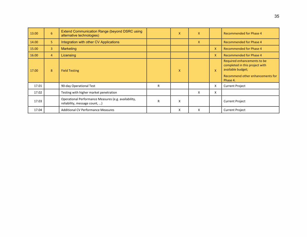
35
13.00 6 Extend Communication Range (beyond DSRC using alternative technologies)
X X Recommended for Phase 4
14.00 5 Integration with other CV Applications X Recommended for Phase 4
15.00 3 Marketing X Recommended for Phase 4
16.00 4 Licensing X Recommended for Phase 4
17.00 8 Field Testing X X
Required enhancements to be completed in this project with available budget;
Recommend other enhancements for Phase 4.
17.01 90-day Operational Test R X Current Project
17.02 Testing with higher market penetration X X
17.03 Operational Performance Measures (e.g. availability, reliability, message count, …) R X Current Project
17.04 Additional CV Performance Measures X X Current Project

36
5 Enhancement of Existing MMITSS Prototypes An iterative and incremental approach will be used in the development. First, the common libraries/components will be developed. The interfaces to these components will be defined through a detailed review of each component that will utilize the interface. This review will identify the objects used in each component and required in the interface. The common component interface will be designed and used to implement the communication between the components. Once these common libraries/components are developed and tested, they will be used in the improvements and refactoring of each of the MMITSS components that implement the traffic control algorithms.
This section discusses enhancements to the MMITSS prototype to ensure the prototype is ready for deployment. In the development of this plan, a review of the current MMITSS prototypes has resulted in identification of several common libraries/components that can be abstracted from the current code base and then updated/improved in the modified code base and used by both the AZ and CA prototypes. Figure 3 illustrates these common components that will support both the MMITSS-AZ and the MMITSS-CA prototypes, as well as other CV applications that could be developed in the same framework.
Figure 3. Common MMITSS Libraries/Components.
Both prototypes need to upgrade the J2735 messages from the 2009 standard to the 2016 standard (2.00). In addition, it is likely that there will be further updates to the SAE J2735 standard and it is desirable to isolate these changes to a single library/component so that future updates will be contained to this library/component. Similarly, an interface to the RSU based on the FHWA 4.1 specification will be developed to isolate the communications between the RSU and the MRP to a single component (3.00). A common Map Data (MAP) library (2.02) will be developed that supports critical MAP related functions such as determining if a vehicle is within the coverage of the map as defined in a MAP message, locating a vehicle on the MAP, estimating the distance from the vehicle to the stop bar, etc.
These common components will be based on the standards that are available to support making applications such as MMITSS hardware agnostic (Phase III Objective), but there are also situations where no standard exists, and vendor specific software will have to be developed. For
Common Libraries/Components J2735 Message Library, RSU 4.1 Interface, MAP Engine, Common Component
Interface NTCIP Library, GPS Library, …
MMITSS – AZ Components
MMITSS – CA Components
Other CV App Components (Work Zone, Ramp Meter, BIM,
EVA, RSA, …)

37
example, there is no OBU interface standard (12.00). Where possible, an interface will be defined and developed that can be ported to other vendors’ devices. However, since the vendor implementations are substantially different, it won’t be possible to ensure that this approach will result in a new interface standard within the scope of this effort.
This approach has implications to the improvements to the source code and documentation as well. Currently, the objects (or structures) that represent the messages that are used in MMITSS include the Basic Safety Message (BSM), MAP, Signal Phase and Timing (SPaT), Signal Request Message (SRM), and Signal Status Message (SSM), which are used as the communication for many of the software components, but they have been modified in each of the components for local use. This impact was an artifact of the development process where individuals developed and tested the different components with only a loose attempt at coordination since the work was focused on new algorithm development and each of the developers added new data to the objects as needed. Hence, the development of a common J2735 message library will also require the development of an interface that allows MMITSS components to get and set message data from a set of common objects that are used throughout the other MMITSS components. These common objects will be the building blocks for each of the MMITSS components and will be utilized in the code improvements (refactoring).
The MMITSS Development Plan has been designed to address these improvements identified above. A sequence of development efforts (e.g. sprints) has been identified that utilizes the AZ and CA team strengths and results in a set of common components to support both of the prototypes. Figure 4 illustrates the development plan that addresses all of the required enhancements and some desired enhancements.
The development plan shows the improvements in MMITSS AZ, MMITSS CA, and the MMITSS Common Components. In addition, a set of MMITSS testing and evaluation tools is being developed based on the VISSIM simulation environment developed by the University of Arizona during the Phase II effort. The VISSIM drivermodel.dll will be updated to provide BSM and SRM messages in the J2735 2016b format. The Docker MRP/RSU simulation will be updated from Docker version 1.01 to version 1.10. In addition, a collection of Unit Test applications will be developed that will support testing individual MMITSS components.
The development plan is intended to establish an open source development community that allows the MMITSS Team to continue development, but also will allow other developers to contribute to the project. The open source process is described in Appendix A.

38
Figure 4. MMITSS Development Plan.

39
6 Prioritized Enhancements for MMITSS Phase 4 The MMITSS Development Plan (Phase III) doesn’t address all of the development items identified. Table 9 summarizes the enhancements that are not planned in the Phase III effort. The enhancements are arranged in order of priority as determined in the ranking process described in Section 4. This list highlights the need for additional traffic control enhancements as well as usability.
Table 9. MMITSS Enhancements for Phase IV (proposed).

40
APPENDIX A. Open Source Repository Collaboration Process
MMITSS Team Collaboration, Common Components, and Shared Libraries
The MMITSS development teams in Arizona and California plan to share components and libraries as much as possible. To support this process, there is a set of private repositories on GitHub (Figure 5) for development, test, and staging for migration to the open source public GitHub repositories.
Figure 5. Private (left) and Public (right) GitHub Repositories.
Once a component or library has been identified as a candidate for re-use, the team that begins development first works in a local ‘sandbox’ repository with input from the other team as stakeholder. When the candidate software is ready to be shared the other team begins development from their side. When ready for release to the main (master) code line, after testing by both teams, the software is pushed to the mmitss-common repository.
Figure 6. Repository Issue Tracking.

41
The process for developing using GitHub repositories includes leaving the master code line as the representation of the latest release. No development work is ever performed directly on that branch. Each repository has an issue tracker (Figure 7) that allows for team-based tracking, open source tracking, and tracking by project. Development is performed using a branch from the develop branch. Typically, a developer names the GitHub branch for their intended effort topic.
Below is an example of the master branch, the develop branch, and a development branch named removeRedundancies. The goal is to make changes to branches as quickly as possible, to simplify merging. After the work is complete, there is a code review on the branch, and once satisfied with the changes, the code is merged back to the develop branch. When all changes are tested and ready, they will be merged back in to the develop branch.
There will likely be multiple local and remote development branches that need to be merged back to the develop branch. Before each merge, the developer must resolve all conflicts between their branch and the current develop branch. After this is done and integrated testing has passed, there is a code review before the merge back to develop. When all of the relevant changes have been merged to the develop branch, the changes are merged back in to the master branch as a release. For that moment, the master branch and the develop branch should contain the same code line.
Figure 7. GitHub branches.
Open Source Collaboration
The project is intended to be Open Source, so the MMITSS core development team expects collaboration and contributions from outside parties. Contribution includes code, configuration,

42
documentation, reporting issues and more. To support that contribution, we use a process for working with collaborators and accepting their input to the process and the project.
The project will be hosted in public repositories on GitHub to ensure access to all interested parties. The project will also be released periodically to the USDOT OSADP site for downloads and use or review by OSADP members. The difference between the two repository platform is that the GitHub platform is intended for downloads and use, as well as contributions (e.g., software, documentation, configuration updates, etc.) and the OSADP site is for registered member downloads.
Figure 8. USDOT OSADP.
On GitHub we have built an organization presence for MMITSS at https://github.com/mmitss (). The core development teams for Arizona and California work across multiple repositories to develop and maintain the source code for MMITSS-AZ, MMITSS-CA, and MMITSS-Common as described above in MMITSS Team Collaboration, Common Components, and Shared Libraries. When a code line has been tested and tagged for release, the teams will merge the release into the relevant public (open source) repositories.

43
Figure 9. MMITSS Organization on GitHub.
All pull requests, whether external or internal, will be reviewed by at least one member of the MMITSS core team. During the review of the pull request the team member will either merge it, request changes to it, or close it with an explanation. For major changes the reviewer may require additional support from the team, which could cause some delay. We'll do our best to provide updates and feedback throughout the process. Feel free to open pull requests, and the MMITSS team will communicate through it with any comments. Before submitting a pull request, please make sure the following is done:
• Fork the repository and create a branch from the develop branch (see image above). • If you've added code that should be tested, add tests. • Ensure the tests pass. Our target is 90% coverage. • Update the documentation. Any appropriate documentation updates (e.g., System Design
Document, User Manual, etc.) should be included in the word document under the `docs/` folder.
• User QA procedures that are documented within the GitHub Wiki. • Please contact the MMITSS team with any questions. • Format your code as outlined in the Style Guide. • When you are finished with integration testing, issue your pull request to the MMITSS
team.

44
APPENDIX B. FHWA GAP ANALYSIS REPORT A High-Level Gap Analysis of Enhancing Current CV Arterial Coordination (MMITSS)
7/7/2016
Introduction
The Intelligent Transportation Systems (ITS) Strategic Plan 2015-20195 identifies six focus areas that the Federal ITS program will pursue over the next five years and details the overall approach for advancing each category from research through field testing to technology transfer to the support of widespread deployment. Connected Vehicle (CV) is one of the identified areas. The United State Department of Transportation (USDOT) Vehicle to Infrastructure (V2I) Safety Program aims to leverage connected vehicle technology in order to develop and evaluate a systems environment that allows transfer of information between vehicles and infrastructure. The program research also involves multiple transportation agencies and modes, which include passenger cars, transit vehicles, freight vehicles, pedestrians, and bicyclists.
Through the Dynamic Mobility Application Program, the USDOT developed and demonstrated the Multi-Modal Intelligent Traffic Signal Systems (MMITSS) bundle of mobility applications. This suite of applications includes traffic signal control using Basic Safety Messages (BSM) from approaching vehicles, broadcasting the Signal Phase and Timing (SPaT) message and MAP message from the signal controller cabinet, managing priority traffic signal control for emergency, transit, freight and agency vehicles, and responding to pedestrian service requests from equipped non-motorized travelers. MMITSS is installed and operational in prototype form in Anthem, Maricopa County, AZ, and in Palo Alto, CA6. The final report for this project that was funded through the Connected Vehicle (CV) Pooled Fund Study (PFS) and delivered to the USDOT in June 2016.
Over the past couple of years, the USDOT continued to reach out to stakeholders to help identify what should be included and considered when developing the next level of research for traffic signal systems and traffic signal operations. To determine what research they should invest in, the USDOT requested a high level gap analysis to see what other research, if any was already underway pertaining to traffic signal operations. This report summarizes some current and anticipated research and deployment underway pertaining to traffic signal operations and identifies some additional activities that the USDOT could undertake to enhance the current applications.
Current MMITSS Overview
5 http://www.its.dot.gov/strategicplan/index.html
6 Connected Vehicles Pooled Fund Study Request to the USDOT for Joint V2I Application Development Work, White Paper, 4/11/2016.

45
The MMITSS final report was submitted on June 9, 2016 and contains both Arizona and California prototypes. Table B1 summarizes the Use Cases that were selected for design, implementation, and field testing based on the characteristics of the two test beds (Arizona and California), resources available for development, and the desire to provide a rich set of multi modal intelligent signal control capabilities. Several use cases were selected to be deferred until future efforts due to resources and network characteristics7.
Table B1. MMITSS Operational Scenarios and Use Cases
Operational Scenarios/Use Cases Include Defer AZ CA MMITSS Operational Scenario
Network Section 1 X X X Network Section 2 X X
Intelligent Traffic Signal System Scenarios
Basic Signal Actuation X X X Coordinated Section of Signals X X X Congestion Control X
Dilemma Zone Protection X X X TSP Operational Scenarios
Basic TSP Scenario and Variations X X X Nearside Bus Stop X
Transit Signal Priority for Left Turn with Protected Signal X
Operational Scenarios for Rail Crossings in Urban Areas X
Extended TSP Scenario X X X Pedestrian Mobility Operational Scenarios
Unequipped Non-Motorized Traveler -
Equipped Non-Motorized Traveler X X X Equipped Bicyclist X
Inclement Weather Accommodations for Non-Motorized Travelers X
Freight Signal Priority Operational Scenarios
Basic Freight Signal Priority X X X Coordinated Freight Signal Priority along a Truck Arterial X X X
Emergency Vehicle Priority
Single Intersection Priority/Preemptions X X
Route Based Intersection Priority/Preemption X
In the final report, several future research and development activities were identified that will continue the development of MMITSS:
7http://www.cts.virginia.edu/wp-content/uploads/2014/05/Task4._SystemDesign_3_Revised_v.2.pdf

46
• Field Testing with Higher Market Penetration – One of the greatest needs is to increase the market penetration of connected vehicles in the test beds to allow real performance observation under more realistic conditions that will exist in the future when new vehicles are equipped with connected vehicle technologies.
• Additional Use Cases – These deferred use cases capture advanced Stakeholder Needs that were identified in the Phase I Stakeholder Needs Assessment activities and should be included in the enhancements of MMITSS.
• Additional Research on Intelligent and Priority Control Algorithms – The recommended enhancements include: Section Level Priority Control; Integration with Coordination; N-Level Priority Policy: Impacts and Effects; Vehicle Dynamics in Priority Requests (Freight, Transit, EV); and Queue Dynamics.
• Freeway Interchange/Ramp Meter Control and Priority – Concepts for advanced ramp metering that use data from connected vehicles should be explored through the same systems engineering process as the current MMITSS. Stakeholders should be engaged to determine their needs.
• Extending the Communication Range beyond DSRC – DSRC was the primary means of communication for the Phase II MMITSS development and testing, but other communications media could provide significant enhancements for many of the MMITSS use cases.
• Integration with other Connected Vehicle Applications – There are potential benefits from integration of some of these other applications with MMITSS. For example, Eco-Approach and Departure integration could create additional benefits for both passenger vehicles, trucks, and transit as well as create interesting opportunities for electric and other alternative fuel vehicles.
• Additional Performance Measures/Observations – Continued enhancement of the MMITSS performance observation capabilities is a valuable contribution to MMITSS as well as other connected vehicle applications.
Ongoing Connected Vehicle Application Enhancements to MMITSS
Through discussions with CV PFS members, the USDOT identified research and deployment activities that are currently being pursued to enhance the MMITSS algorithms and applications. Below is a summary of the information collected on these activities.
Discussion with Larry Head – Professor, University of Arizona
Larry is working on several projects and has students working on research projects enhancing the applications developed under the MMITSS umbrella identified above. Students are working on components of the applications that need to be made deployment ready. In addition, Larry will be working with the Port of San Diego on a project involving the Freight Signal Priority application, the Columbus, Ohio Smart City Challenge project to assist with the MMITSS functionality identified in their proposal (see table below), and with Utah DOT to develop.
Larry identified the following activities to enhance the MMITSS bundle of applications:
• Updates provided in the 2016 SAE J2735 standard will improve the MAP messages. • Creating independence from the Savari roadside equipment (RSE) build. The MMITSS
application software resides on the Savari RSE unit. Not having an independent platform for the software and the RSE limits an agency to what equipment can be purchased.
• Creating a user interface making the application easier to install and operate. Larry has a student working on this functionality.
• A student is also working on Performance monitoring and collecting data into data sets that can be shared on the Research Data Exchange (RDE).

47
• Savari is working on a pedestrian/bicycle application called Savari SmartCross; however, again it will be proprietary.
• Mehdi Zamanipour, a graduate student at the university and currently working at the USDOT is continuing research on the MMITSS application and integration with coordination.
• Some type of Configuration Management of MMITSS. Is there a role for continued software maintenance? Or is this something the traffic signal controller vendors will do and each do their own configuration management? Should this be maintained or put out to the industry to maintain?
Discussion with Blaine Leonard, ITS Program Manager at Utah Department of Transportation
Blaine Leonard is a member of the CV PFS and currently has a project in Salt Lake City to provide Transit Signal Priority through the MMITSS TSP application. They were interested in deploying DSRC and build a foundation for future deployment and MMITSS was the most advanced application to start that process. There were a couple of issues they found as they began to implement the TSP application.
• The software from the Open Source Application Development Portal (OSADP) was not deployment ready. The MMITSS bundle that is available only works with Savari RSEs, creating a proprietary system, which they did not want to do. They are working with Larry Head to develop a generic interface that will work with all approved RSEs and they will be sharing this on the OSADP.
• They were concerned that the 300 meter range of the communication units did not provide enough time within a cycle length for the signal to respond appropriately to the approaching vehicle. So Larry will also be working with them to develop a Peer-to-Peer module giving the controller enough time to respond appropriately to the approaching vehicle. They will also be sharing this on the OSADP when completed.
These two changes to the software could make the applications ready for deployment in other agencies systems, only requiring the agency to provide their own MAP data.
The USDOT Sponsored Deployments
• Connected Vehicle Pilot Deployment Program
Among the three pilot sites, NYCDOT and Tampa (THEA) pilot sites proposed the deployment of the applications within MMITSS bundle and signal related applications. The table below lists the related applications and the description from the Application Deployment Plans.
Pilot Site Application Description Enhancement
NYCDOT
Mobile Accessible Pedestrian Signal System (PED-SIG)
This application will reside on smart phones or other types of Personal Information Device (PID) that is carried by visually impaired pedestrians. The application could, in principle, be handled by one-way communication from the traffic signal
This application may be developed specifically for the New York City project, or the code may be obtained and adapted from MMITSS.

48
to the device in the pedestrian’s hand.
Tampa (THEA)
Intelligent Traffic Signal System (I-SIG)
I-SIG uses vehicle location and movement information from CVs as well as infrastructure measurement from non-equipped vehicles to improve traffic signal control operation and maximize flows in real time.
Tampa (THEA) will use the code in the OSADP as a start point. These applications would require a major overhaul of some algorithm modules due to how it will be deployed in the Tampa pilot.
Mobile Accessible Pedestrian Signal System (PED-SIG)
This application will enable a "pedestrian call" to be routed to the traffic controller from a nomadic device of a registered person with disabilities, after confirming the direction and orientation of the roadway that this pedestrian is intending to cross. The application also provides warnings to the personal information device user of possible crossing infringement by approaching vehicles.
Transit Signal Priority (TSP)
TSP uses transit V2I communications to allow a transit vehicle to request a priority at one or a series of intersections based on a number of factors. Once TSP is implemented, if a bus is behind schedule, the traffic signal system will give the bus priority assuming there are no other higher priorities (such as a preemption request or an on-going pedestrian phase).
• Smart City Challenge
The evaluation of the seven finalists for the Smart City Challenge indicated that all seven finalists would be deploying some form of the MMITSS applications. The winning city, Columbus Ohio intends on deploying Transit Signal Priority and Freight Signal Priority as part of the MMITSS bundle and will be including the deployment of Eco-Approach and Departure at Signalized Intersections and Red Light Violation Warning. The USDOT will be working with the other finalists to find opportunities for them to deploy systems and will continue to monitor the proposed deployments with the intent to not duplicate any proposed deployments within the upcoming research plan. The table below identifies the planned MMITSS applications.

49
Multimodal Traffic Signal System (MMITSS) Intelligent
Traffic Signal Systems for Connected Vehicles (ISIG)
Transit Signal Priority
Freight Signal Priority
Emergency Vehicle Preemption
Pedestrian Detection and Warnings
Columbus OH X X X X
Austin TX X X X X
Denver CO X X Kansas City MO X X X X X
Portland OR X X X X X
Pittsburgh PA* X X X San Francisco CA X X X X
* Pittsburgh would deploy Surtrac real-time adaptive traffic signal system with DSRC (Proprietary)
Other Traffic Signal Research
There are many other research projects throughout the US and internationally looking at using connected vehicle technologies to improve traffic signal operations. A detailed gap analysis should be included in the USDOT’s future research effort to take advantage of existing research and avoid duplication.
Conclusions
This high level analysis has determined that most of the current projects and research are concentrated on making the existing MMITSS bundle and associated applications readily deployable, working on an improved interface with the traffic signal controller, extending the DSRC range and developing a generic software application. With these functions being examined by others, the USDOT research effort should focus on the complexity and interaction of traffic as it moves between arterials and freeways to optimize operations so as to provide reliable travel. A proposed Multimodal Intelligent Traffic Operations System (MMITOS) research plan should seek to enhance current MMITSS applications by pursuing coordinated and adaptive traffic signal control, pursue interchange and ramp metering operations and incorporate arterial traffic control operations with other connected vehicle applications such as Integrated Network Flow Optimization (INFLO). In addition, research should address the deferred use cases identified in previous MMITSS research and not currently being pursued by other deployment or research. An important component of the next research plan needs to include coordination with other

50
deployers/standard groups/CAMP/OEMs. This interaction should be required to show coordination/collaboration to build on existing research and avoid duplication where possible.

51
APPENDIX C. MMITSS Development Group Roster
MMITSS Development Group (MDG) Membership Roster
Meeting Date: May 2-3, 2018
Name Organization Role MMITSS Software Knowledge
John Amadon Narwhal Group (UDOT) Developer Expert - MMITSS-AZ
Eric Raamot Econolite Developer Some - MMITSS-AZ (Phase I team member)
Doug Tarico McCain Developer Low
Michael Venus Siemens Developer High - THEA CV Pilot
Grant Gardner Intelight Developer High
Mehdi Zamanipour TRB/FHWA Fellow Developer Expert - MMITSS-AZ Team (Priority)
Yiheng Feng UMTRI - Michigan Developer Expert - MMITSS-AZ Team (I-SIG)
Greg Zink Battelle Developer Some - Broad
Chris Stanley Leidos Developer V2I-Hub
Ravi Puvvala Savari RSU/OBU Some - MMITSS (Phase I &2 team member)
Daniel Kiel Cohda RSU/OBU Hardware
Paul Maeda Lear RSU/OBU Hardware
Brian Wells Denso RSU/OBU Some - OBU R/Q
Kristin Tufte USDOT Developer USDOT JPO ODE Process
Burak Cesme Kittleson & Assoc. Integrator Low
George Chen LA DOT Agency Low
Gary Miskell VTA Transit Operator Medium
Tom Timcho WSP Integrator Medium
Greg Larson Caltrans Agency CV PFS Panel - Champion
Faisal Saleem MCDOT Agency CV PFS Panel - Champion
Gene McHale FHWA Sponsor CV PFS Panel - Champion
Govind Vadakpat FHWA Sponsor CV PFS Panel
Deborah Curtis FHWA Sponsor CV PFS Panel
Blaine Leonard UDOT Agency CV PFS Panel
Chuck Felice UDOT Agency/Developer CV PFS Panel Virginia Lingham VDOT Agency CV PFS Panel
Jianming Ma TxDOT Agency CV PFS Panel Raj Ponnaluri FDOT Agency CV PFS Panel
Hua Xiang MDOT Agency CV PFS Panel

52
Ahmad Jawad Oakland County Agency CV PFS Panel
Reza Karimvand ADOT Agency CV PFS Panel
Ray Derr TRB Research CV PFS Panel - Reference
Hyungjun Park UVA Research CV PFS Panel
Steven Smith CMU Research Lee Mixon Mixon Hill Larry Head UA Developer Team Member
Sherilyn Keaton UA Developer Team Member
Kun Zhou PATH Developer Team Member
Ben McKeever PATH Developer Team Member
John Spring PATH Developer Team Member
Sean Laffey AECOM Integrator System Integration Interest
Pater Carnes TrafficCast RSU/OBU hardware (Denso)+System Integration
Peiwei Wang USDOT tech support: V2I Program
James Chang USDOT tech support: V2I Program
Bob Frey THEA CV Pilot Agency Medium
Steve Novosad HNTB Integrator Medium
Ariel Gold USDOT JPO Federal Low Camille Crichton-Sumners TRB Peter Thompson SANDAG Agency Medium Vanloan Nguyen VDOT Agency CV PFS Panel
Michael Clements VDOT Agency CV PFS Panel