multi-physics analysis for rubber-cement applications in
TRANSCRIPT
sustainability
Article
Multi-Physics Analysis for Rubber-CementApplications in Building and Architectural Fields:A Preliminary Analysis
Marco Valente 1,2,* , Matteo Sambucci 1,2, Abbas Sibai 1 and Ettore Musacchi 3
1 Department of Chemical and Material Engineering, Sapienza University of Rome, 00184 Rome, Italy;[email protected] (M.S.); [email protected] (A.S.)
2 INSTM Reference Laboratory for Engineering of Surface Treatments, Department of Chemical andMaterial Engineering, Sapienza University of Rome, 00184 Rome, Italy
3 European Tyre Recycling Association (ETRA), 1040 Brussels, Belgium; [email protected]* Correspondence: [email protected]; Tel.: +39-06-4458-5582
Received: 3 June 2020; Accepted: 23 July 2020; Published: 25 July 2020�����������������
Abstract: Generally, in most countries, there are no strict regulations regarding tire disposal.Hence, tires end up thrown in seas and lands as well as being burnt, harming the living beings,and are therefore considered a very dangerous pollution source for the environment. Over the pastfew years, several researchers have worked on incorporating shredded/powdered rubber tires intocement-based material. This strategy shows a dual functionality: Economic–environmental benefitsand technological functionalization of the building material. Rubber-modified cement materialsshow interesting engineering and architectural properties due to the physical-chemical nature ofthe tire rubber aggregates. However, the abovementioned performances are affected by type, size,and content of polymer particles used in the cement-based mixtures production. Whereas an increasein the rubber content in the cement mix will negatively affect the mechanical properties of the materialas a decrease in its compression strength. This aspect is crucial for the use of the material in buildingapplications, where proper structural integrity must be guaranteed. In this context, the developmentof innovative manufacturing technologies and the use of multi-physics simulation software representuseful approaches for the study of shapes and geometries designed to maximize the technologicalproperties of the material. After an overview on the performances of 3D printable rubber-cementmixtures developed in our research laboratory, a preliminary experimental Finite Element Method(FEM) analysis will be described. The modeling work aims to highlight how the topology optimizationallows maximizing of the physical-mechanical performances of a standard rubber-cement componentfor building-architectural applications.
Keywords: tire crumb rubber; rubber-cement mortars; additive manufacturing; FEM-basedmechanical analysis; structural optimization; design
1. Introduction
Recycling processes, applied to the construction industry, aim to save the environment by reducingthe need for extracting, refining, and processing mineral aggregates, as well as reducing wastes thathave a negative impact as harmful chemicals and greenhouse gasses. In this context, the role of materialengineering is to recycle theses wastes and ensure that these new materials are functional again forindustries to produce new products and cementitious compounds for a cheaper price and with a lowerenvironmental impact [1].
Waste tires are one of the main social and environmental issues worldwide. With the increase inthe automotive industry, large amounts of waste tires cumulate in the world each year. Specifically,
Sustainability 2020, 12, 5993; doi:10.3390/su12155993 www.mdpi.com/journal/sustainability
Sustainability 2020, 12, 5993 2 of 21
an annual production of nearly 1 billion tires is estimated. Over 50% of these are discarded in landfillsor stored in underground sites, without any treatment. Due to their poor biodegradability andimpermeable nature, tires store water for a longer period, providing breeding habitats for the pests.This effect inevitably promotes soil pollution and the spread of many diseases [2,3]. Burning is anothermethod for tire disposal, but the high temperatures involved in the thermal treatment imply theuncontrolled release of toxic gas and benzene compounds, potentially harmful to living beings andatmosphere [2].
As a promising solution to the tire disposal problem, the strategy based on the incorporationof rubber particles (produced by shredding and commutating used tires) in cementitious matriceshas gained considerable attraction from many researchers working in the civil engineering andbuilding sectors [3–5]. According to the previous works, the physical and viscoelastic propertiesof the recycled tire rubber aggregates confer to concrete material interesting engineering properties:Elasticity, lightweight, vibration damping, durability, sound, and thermal insulation [6,7]. However,the mechanical strength of rubberized material decreases significantly as the rubber content increase.This limits the incorporation of a large amount of polymer aggregates in the cement matrix, and hindersthe use of these mixtures in several structural applications [8].
The mechanical weakness of the rubber-cement mixtures is the starting point of this research work.The main topic of this work is to combine the skills of materials engineering with the possibilitiesoffered by the architectural design in order to maximize the physical–mechanical behavior throughtopological optimization approach. This means studying and testing functional shapes and geometriesto be scaled in the manufacturing of rubber-cement bricks or building components. As highlightedby several research works, the type of perforated structure of brick can significantly influence itsstructural, thermal, and acoustic efficiency [9,10]. Thanks to the progress of the technical drawing andFEM (Finite Element Method) analysis software, it will be possible to perform rigorous studies onthe physical–mechanical behavior offered by different morphology design. In this case, the aim ofstructural modeling is to select the shape of the inner holes that maximizes the mechanical performanceof the component, also improving its lightness and thermo-acoustic efficiency.
The first part of the paper presents the mixes design and the experimental physical–mechanicalcharacterization of several tire rubber-cement mortars obtained by total volume replacement of thesand with a different grain size of crumb rubber (0–1 mm rubber powder and 2–4 mm rubber granules).The innovative aspect of these cementitious mixtures concerns the possibility of using them in AdditiveManufacturing (AM) processes. Indeed, the mix proportions were optimized to obtain rheology andwet properties suitable for the extrusion-based printing process. Such technology promotes potentialbenefits in the construction field (cost-effective, high efficiency, reduction in labor for safety reasons,environmentally friendly, design flexibility) and is therefore well suited to the automated productionof complex structures that would often be difficult to produce using traditional manufacturingmethods [11–13].
Specifically, three types of printable mixtures have been developed and investigated:
• Control mix: Standard cement mortar (100% sand) used as the basis for the preparation of therubberized mixes and for comparison purposes.
• P100 mix: Rubberized cement mortar obtained by total replacement of the sand withrubber powder.
• P-G50/50 mix: Rubberized cement mortar obtained by total replacement of the sand with an equalproportion of rubber powder and rubber granules.
The goal of this investigation is to evaluate the effect of the rubber aggregates’ size on the structuraland performance of the material and to select the type of rubberized mixture with less mechanical lossthan the standard mix. The “best” formulation was used as a benchmark rubber-cement mix for thecomputational analysis described below.
Sustainability 2020, 12, 5993 3 of 21
To complete the discussion on the printable rubber-cement compounds, FEM-based mechanicalanalysis is presented. This study is an advanced approach to enhance the properties of buildingmaterials and to investigate their possible technological applicability. In this regard, the proposalis to exploit the design flexibility, related to AM processes, to develop a rubber-cement brick withan engineering functional design. As a preliminary research stage, the effect of different innermorphologies on the mechanical performances was evaluated. Three types of brick designs were testedand compared with a reference component (unperforated brick): Two conventional geometries (roundand square holes) and one unconventional inner structure (hexagonal holes). Referring to MunozGuzman et al.’s research work [10], a honeycomb design would result in a relevant improvement inmechanical strength and thermo-acoustic damping compared to conventional cavities. The numericalsimulation was performed using the commercial finite element software COMSOL Multiphysics v5.4.By the Structural Mechanics Module, a uniaxial compression test was simulated to reproduce the loadconditions reported in ASTMC 67-03a standard [14]. The output FEM results were stress–strain curves,from which the mechanical properties (compressive strength and Young’s modulus) were extrapolatedfor each type of brick prototype tested. The possibility of using the rubber-cement compounds indigital manufacturing methods implies a relevant versatility from design and architectural freedompoints of view. In this regard, a concept of shape-optimized hollow brick with novel easy-to-assemblestructure is also presented.
2. Materials and Methods
2.1. Materials, Print Process, and Samples Preparation
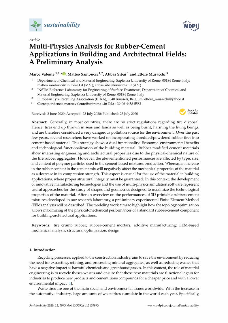
In this research, two different granular samples of recycled tire crumb rubber (ETRA, European TyreRecycling Association) were used: Rubber powder (0–1 mm size) and rubber granules (2–4 mm size).The average density of the waste rubber particles, evaluated by Micromeritics AccuPyc 1330He-pycnometer, is 1202 kg/m3. An image of the crumb rubber used in this work is shown inFigure 1.
Sustainability 2020, 12, x FOR PEER REVIEW 3 of 21
to exploit the design flexibility, related to AM processes, to develop a rubber-cement brick with an engineering functional design. As a preliminary research stage, the effect of different inner morphologies on the mechanical performances was evaluated. Three types of brick designs were tested and compared with a reference component (unperforated brick): Two conventional geometries (round and square holes) and one unconventional inner structure (hexagonal holes). Referring to Munoz Guzman et al.’s research work [10], a honeycomb design would result in a relevant improvement in mechanical strength and thermo-acoustic damping compared to conventional cavities. The numerical simulation was performed using the commercial finite element software COMSOL Multiphysics v5.4. By the Structural Mechanics Module, a uniaxial compression test was simulated to reproduce the load conditions reported in ASTMC 67-03a standard [14]. The output FEM results were stress–strain curves, from which the mechanical properties (compressive strength and Young’s modulus) were extrapolated for each type of brick prototype tested. The possibility of using the rubber-cement compounds in digital manufacturing methods implies a relevant versatility from design and architectural freedom points of view. In this regard, a concept of shape-optimized hollow brick with novel easy-to-assemble structure is also presented.
2. Materials and Methods
2.1. Materials, Print Process, and Samples Preparation
In this research, two different granular samples of recycled tire crumb rubber (ETRA, European Tyre Recycling Association) were used: Rubber powder (0–1 mm size) and rubber granules (2–4 mm size). The average density of the waste rubber particles, evaluated by Micromeritics AccuPyc 1330 He-pycnometer, is 1202 kg/m3. An image of the crumb rubber used in this work is shown in Figure 1.
Figure 1. Crumb rubber used in this work.
To produce the rubberized mixtures, the polymer aggregates were incorporated in total volumetric replacement of the sand constituting a 3D printable standard cement mortar (labeled as Control). Control mix composition is described next (dosage for 1 m3):
• Type I Portland cement: 800 kg • Limestone sand (maximum size of 0.4 mm): 1100 kg • Water: 300 kg • Relation water to cement (w/c ratio): 0.375 • Silica fume: 120 kg • Chemical additives (expansive agent, superfluidifying and reducer additives): 32 kg Starting with this composition, specific sand-rubber replacements were performed to obtain
two sets of rubber-cement mortars (labeled as P100 and P-G50/50, respectively). The preparation of the investigated fresh mixtures was based on a three-step process: Premix, water addition, and mixing. In premix stage, dry constituents were weighed and mixed to ensure a homogeneous compound. Next, water was added to promote the cement hydration reaction. The proper dosage of water has been selected to obtain a specific w/c ratio and therefore achieve certain mechanical properties. Water-dry materials mixing was performed with an electric mixer drill for a time not
Figure 1. Crumb rubber used in this work.
To produce the rubberized mixtures, the polymer aggregates were incorporated in total volumetricreplacement of the sand constituting a 3D printable standard cement mortar (labeled as Control).Control mix composition is described next (dosage for 1 m3):
• Type I Portland cement: 800 kg• Limestone sand (maximum size of 0.4 mm): 1100 kg• Water: 300 kg• Relation water to cement (w/c ratio): 0.375• Silica fume: 120 kg• Chemical additives (expansive agent, superfluidifying and reducer additives): 32 kg.

Sustainability 2020, 12, 5993 4 of 21
Starting with this composition, specific sand-rubber replacements were performed to obtain twosets of rubber-cement mortars (labeled as P100 and P-G50/50, respectively). The preparation of theinvestigated fresh mixtures was based on a three-step process: Premix, water addition, and mixing.In premix stage, dry constituents were weighed and mixed to ensure a homogeneous compound. Next,water was added to promote the cement hydration reaction. The proper dosage of water has beenselected to obtain a specific w/c ratio and therefore achieve certain mechanical properties. Water-drymaterials mixing was performed with an electric mixer drill for a time not exceeding 12 min. This timeinterval allowed the optimal effect of the superplasticizer additive and the obtainment of rheologicalproperties compatible with the extrusion system used in this research.
To develop the printable rubber-cement compounds, all mix design parameters were kept constantexcept for the rubber aggregates constituents and the w/c ratio. In P100 mix, the sand was totally replacedwith the finest rubber fraction (rubber powder). In P-G50/50 mix, the rubber content was divided equallybetween the powder and granules. The optimum fluidity and consistency, related both to the printingmachine requirements and to the material extrudability [13], were analyzed through printability testsaimed to evaluate the print quality of the fresh compounds (easy-flowing, shape stability, buildability)and the structural features of the printed object (surface finish, inter-layer adhesion). These experimentalanalyses were performed at the Dept. of Materials, Environmental Sciences, and Urban Planning,Marche Polytechnic University (Italy), our technical supporter in the manufacturing processes,and owner of the printing apparatus. Additional details of printability test are available in previouswork from our research activity [15]. Optimum mix designs of rubberized compounds are shown inTable 1.
Table 1. Mix proportions of rubberized compounds.
Mix Design P100 P-G50/50
Cement [kg/m3] 800 800Water [kg/m3] 260 250
w/c ratio 0.325 0.312Sand [kg/m3] 0 0
Silica fume [kg/m3] 120 120Rubber pwd. [kg/m3] 300 150Rubber gran. [kg/m3] 0 160
Additives [kg/m3] 32 32
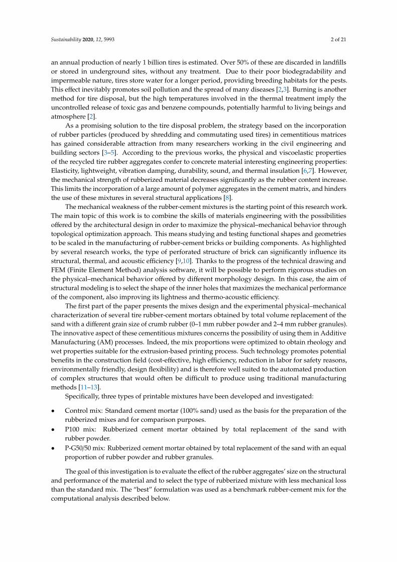
For the printability test, a circular nozzle (Ø = 10 mm) was used to deposit the control andrubberized mortars layer by layer. The extruder is fixed on a 3-axis COMAU robotic arm, which performsa print path in accordance with the three-dimensional model data of the desired sample. The controlsrelating to robotic arm motion and the setting of the printing parameters were monitored throughCura® slicing software. The fresh material was placed in an Aluminum container connected to aperistaltic pump. The pumping allowed to convey the material to the printing nozzle through a PVChose pipe. During the entire process, the pump flow rate and the printing speed (33 mm/s) werekept constant to avoid adverse effects on print quality. For each mixture, six-layer rectangular slabs(220 mm × 160 mm × 55 mm) were manufactured (Figure 2).
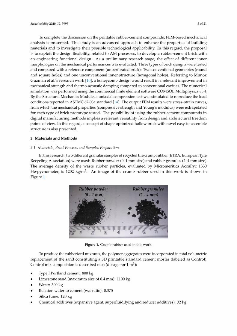
After the printing process, three types of specimens were taken out from the hardened slabs(Figure 2b) by sawing with a diamond blade:
• 48 mm × 42 mm × 22 mm blocks (Figure 3a)• 50 mm-side cubes (Figure 3b)• 40 mm × 40 mm × 230 mm beams (Figure 3c).
Sustainability 2020, 12, 5993 5 of 21
Sustainability 2020, 12, x FOR PEER REVIEW 4 of 21
exceeding 12 minutes. This time interval allowed the optimal effect of the superplasticizer additive and the obtainment of rheological properties compatible with the extrusion system used in this research.
To develop the printable rubber-cement compounds, all mix design parameters were kept constant except for the rubber aggregates constituents and the w/c ratio. In P100 mix, the sand was totally replaced with the finest rubber fraction (rubber powder). In P-G50/50 mix, the rubber content was divided equally between the powder and granules. The optimum fluidity and consistency, related both to the printing machine requirements and to the material extrudability [13], were analyzed through printability tests aimed to evaluate the print quality of the fresh compounds (easy-flowing, shape stability, buildability) and the structural features of the printed object (surface finish, inter-layer adhesion). These experimental analyses were performed at the Dept. of Materials, Environmental Sciences, and Urban Planning, Marche Polytechnic University (Italy), our technical supporter in the manufacturing processes, and owner of the printing apparatus. Additional details of printability test are available in previous work from our research activity [15]. Optimum mix designs of rubberized compounds are shown in Table 1.
Table 1. Mix proportions of rubberized compounds.
Mix Design P100 P-G50/50 Cement [kg/m3] 800 800 Water [kg/m3] 260 250
w/c ratio 0.325 0.312 Sand [kg/m3] 0 0
Silica fume [kg/m3] 120 120 Rubber pwd. [kg/m3] 300 150 Rubber gran. [kg/m3] 0 160
Additives [kg/m3] 32 32
For the printability test, a circular nozzle (Ø = 10 mm) was used to deposit the control and rubberized mortars layer by layer. The extruder is fixed on a 3-axis COMAU robotic arm, which performs a print path in accordance with the three-dimensional model data of the desired sample. The controls relating to robotic arm motion and the setting of the printing parameters were monitored through Cura® slicing software. The fresh material was placed in an Aluminum container connected to a peristaltic pump. The pumping allowed to convey the material to the printing nozzle through a PVC hose pipe. During the entire process, the pump flow rate and the printing speed (33 mm/s) were kept constant to avoid adverse effects on print quality. For each mixture, six-layer rectangular slabs (220 mm x 160 mm x 55 mm) were manufactured (Figure 2).
(a) (b)
Figure 2. Extrusion of fresh material (P100 mix) during the printability test (a) and six-layer 3D printed slab in hardened state (b).
After the printing process, three types of specimens were taken out from the hardened slabs (Figure 2b) by sawing with a diamond blade:
Figure 2. Extrusion of fresh material (P100 mix) during the printability test (a) and six-layer 3D printedslab in hardened state (b).
Sustainability 2020, 12, x FOR PEER REVIEW 5 of 21
• 48 mm × 42 mm × 22 mm blocks (Figure 3a) • 50 mm-side cubes (Figure 3b) • 40 mm × 40 mm × 230 mm beams (Figure 3c)
(a)
(b)
(c)
Figure 3. Specimens for physical and mechanical experimental testing: Blocks (a), cubes (b), and beams (c).
2.2. Testing Program
The physical and mechanical characterization included bulk density, porosity, compressive, and four-point flexural tests after 28 days of ambient curing. Four replicate samples were tested for
Figure 3. Specimens for physical and mechanical experimental testing: Blocks (a), cubes (b), and beams (c).

Sustainability 2020, 12, 5993 6 of 21
2.2. Testing Program
The physical and mechanical characterization included bulk density, porosity, compressive,and four-point flexural tests after 28 days of ambient curing. Four replicate samples were tested for eachmix (control and rubberized compounds). Details of the experimental campaign are described below.
2.2.1. Physical Characterization: Bulk Density and Permeable Porosity
Bulk density was determined by geometric measurement and weighing on oven-dried blocks(110 ◦C for 24 h).
Based on ASTM C 1220 standard [16], the permeable porosity (P%) test was conducted. The blocksare weighed under three conditions: Oven-dried (110 ◦C for 2 h), vacuum-saturated (0.3 bar for 3 hin a desiccator connected to a vacuum pump), and distilled water-saturated (total soaked for 24 h).Then, the obtained weights (Wdry, Wsat, and Wwat, respectively) are used to calculate P% based on thefollowing equation (Equation (1)):
P% =Wsat −Wdry
Wsat −Wwat(1)
2.2.2. Mechanical Characterization: Four-Point Flexural and Uni-Axial Compressive Tests
Four-point flexural tests (ASTM C 348) [17] were performed on a Zwick-Roell Z010 (10 kN)universal testing machine. Beams were tested to evaluate the effect of the rubber aggregates on Young’smodulus and flexural strength of the material. The span length was 180 mm, and the loading rate was1 mm/min. Figure 4a shows the details of the flexural test setup.
Sustainability 2020, 12, x FOR PEER REVIEW 6 of 21
each mix (control and rubberized compounds). Details of the experimental campaign are described below.
2.2.1. Physical Characterization: Bulk Density and Permeable Porosity
Bulk density was determined by geometric measurement and weighing on oven-dried blocks (110 °C for 24 hours).
Based on ASTM C 1220 standard [16], the permeable porosity (P%) test was conducted. The blocks are weighed under three conditions: Oven-dried (110 °C for 2 hours), vacuum-saturated (0,3 bar for 3 hours in a desiccator connected to a vacuum pump), and distilled water-saturated (total soaked for 24 hours). Then, the obtained weights (Wdry, Wsat, and Wwat, respectively) are used to calculate P% based on the following equation (equation 1): P% = W WW W (1)
2.2.2. Mechanical Characterization: Four-Point Flexural and Uni-Axial Compressive Tests
Four-point flexural tests (ASTM C 348) [17] were performed on a Zwick-Roell Z010 (10 kN) universal testing machine. Beams were tested to evaluate the effect of the rubber aggregates on Young’s modulus and flexural strength of the material. The span length was 180 mm, and the loading rate was 1 mm/min. Figure 4a shows the details of the flexural test setup.
Procedures for the uniaxial compressive test complied to ASTM C 109/109M standard [18]. The test was conducted on cube specimens subjected to an axial load applied by a Zwick-Roell Z150 (150 kN) machine with 1 mm/min rate (Figure 4b). For each mixture, the compressive strength result is the average of four specimens.
(a) (b)
Figure 4. Mechanical tests experimental setup: Four-point flexural test (a) and uni-axial compressive test (b).
From experimental stress–strain curves, the compression toughness index (ASTM C 1018-97) [19] was also evaluated. This dimensionless parameter represents the relation between the plastic and elastic regions, then provides a measure of energy absorption capacity of the material. The index was computed by dividing the total area under the stress–strain curve up to a specific service level strain (Tsl) by the area under the same curve up to the peak stress (Tp). According to Khaloo et al.’s [20] work, 80% of peak stress was considered as service level. Figure 5 illustrates how each of the areas was determined from an experimental graph.
Figure 4. Mechanical tests experimental setup: Four-point flexural test (a) and uni-axial compressivetest (b).
Procedures for the uniaxial compressive test complied to ASTM C 109/109M standard [18]. The testwas conducted on cube specimens subjected to an axial load applied by a Zwick-Roell Z150 (150 kN)machine with 1 mm/min rate (Figure 4b). For each mixture, the compressive strength result is theaverage of four specimens.
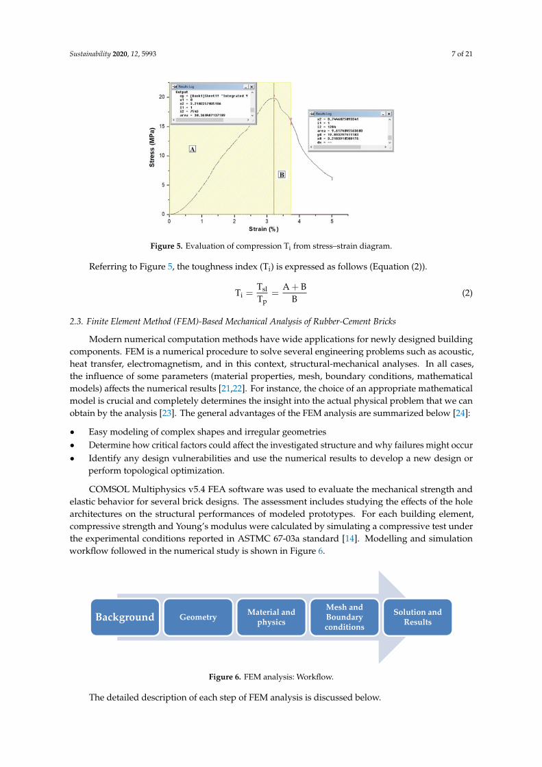
From experimental stress–strain curves, the compression toughness index (ASTM C 1018-97) [19]was also evaluated. This dimensionless parameter represents the relation between the plastic andelastic regions, then provides a measure of energy absorption capacity of the material. The index wascomputed by dividing the total area under the stress–strain curve up to a specific service level strain(Tsl) by the area under the same curve up to the peak stress (Tp). According to Khaloo et al.’s [20] work,80% of peak stress was considered as service level. Figure 5 illustrates how each of the areas wasdetermined from an experimental graph.
Sustainability 2020, 12, 5993 7 of 21Sustainability 2020, 12, x FOR PEER REVIEW 7 of 21
Figure 5. Evaluation of compression Ti from stress–strain diagram.
Referring to Figure 5, the toughness index (Ti) is expressed as follows (equation 2). T = TT = A + BB (2)
2.3. Finite Element Method (FEM)-Based Mechanical Analysis of Rubber-Cement Bricks
Modern numerical computation methods have wide applications for newly designed building components. FEM is a numerical procedure to solve several engineering problems such as acoustic, heat transfer, electromagnetism, and in this context, structural-mechanical analyses. In all cases, the influence of some parameters (material properties, mesh, boundary conditions, mathematical models) affects the numerical results [21,22]. For instance, the choice of an appropriate mathematical model is crucial and completely determines the insight into the actual physical problem that we can obtain by the analysis [23]. The general advantages of the FEM analysis are summarized below [24]:
• Easy modeling of complex shapes and irregular geometries • Determine how critical factors could affect the investigated structure and why failures
might occur • Identify any design vulnerabilities and use the numerical results to develop a new design or
perform topological optimization COMSOL Multiphysics v5.4 FEA software was used to evaluate the mechanical strength and
elastic behavior for several brick designs. The assessment includes studying the effects of the hole architectures on the structural performances of modeled prototypes. For each building element, compressive strength and Young’s modulus were calculated by simulating a compressive test under the experimental conditions reported in ASTMC 67-03a standard [14]. Modelling and simulation workflow followed in the numerical study is shown in Figure 6.
Figure 6. FEM analysis: Workflow.
The detailed description of each step of FEM analysis is discussed below.
Background Geometry Material and physics
Mesh and Boundary conditions
Solution and Results
Figure 5. Evaluation of compression Ti from stress–strain diagram.
Referring to Figure 5, the toughness index (Ti) is expressed as follows (Equation (2)).
Ti =Tsl
Tp=
A + BB
(2)
2.3. Finite Element Method (FEM)-Based Mechanical Analysis of Rubber-Cement Bricks
Modern numerical computation methods have wide applications for newly designed buildingcomponents. FEM is a numerical procedure to solve several engineering problems such as acoustic,heat transfer, electromagnetism, and in this context, structural-mechanical analyses. In all cases,the influence of some parameters (material properties, mesh, boundary conditions, mathematicalmodels) affects the numerical results [21,22]. For instance, the choice of an appropriate mathematicalmodel is crucial and completely determines the insight into the actual physical problem that we canobtain by the analysis [23]. The general advantages of the FEM analysis are summarized below [24]:
• Easy modeling of complex shapes and irregular geometries• Determine how critical factors could affect the investigated structure and why failures might occur• Identify any design vulnerabilities and use the numerical results to develop a new design or
perform topological optimization.
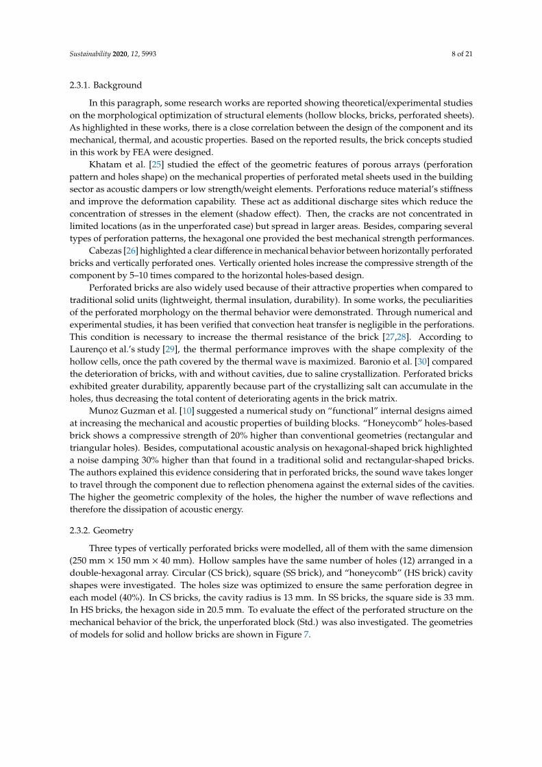
COMSOL Multiphysics v5.4 FEA software was used to evaluate the mechanical strength andelastic behavior for several brick designs. The assessment includes studying the effects of the holearchitectures on the structural performances of modeled prototypes. For each building element,compressive strength and Young’s modulus were calculated by simulating a compressive test underthe experimental conditions reported in ASTMC 67-03a standard [14]. Modelling and simulationworkflow followed in the numerical study is shown in Figure 6.
Sustainability 2020, 12, x FOR PEER REVIEW 7 of 21
Figure 5. Evaluation of compression Ti from stress–strain diagram.
Referring to Figure 5, the toughness index (Ti) is expressed as follows (equation 2). T = TT = A + BB (2)
2.3. Finite Element Method (FEM)-Based Mechanical Analysis of Rubber-Cement Bricks
Modern numerical computation methods have wide applications for newly designed building components. FEM is a numerical procedure to solve several engineering problems such as acoustic, heat transfer, electromagnetism, and in this context, structural-mechanical analyses. In all cases, the influence of some parameters (material properties, mesh, boundary conditions, mathematical models) affects the numerical results [21,22]. For instance, the choice of an appropriate mathematical model is crucial and completely determines the insight into the actual physical problem that we can obtain by the analysis [23]. The general advantages of the FEM analysis are summarized below [24]:
• Easy modeling of complex shapes and irregular geometries • Determine how critical factors could affect the investigated structure and why failures
might occur • Identify any design vulnerabilities and use the numerical results to develop a new design or
perform topological optimization COMSOL Multiphysics v5.4 FEA software was used to evaluate the mechanical strength and
elastic behavior for several brick designs. The assessment includes studying the effects of the hole architectures on the structural performances of modeled prototypes. For each building element, compressive strength and Young’s modulus were calculated by simulating a compressive test under the experimental conditions reported in ASTMC 67-03a standard [14]. Modelling and simulation workflow followed in the numerical study is shown in Figure 6.
Figure 6. FEM analysis: Workflow.
The detailed description of each step of FEM analysis is discussed below.
Background Geometry Material and physics
Mesh and Boundary conditions
Solution and Results
Figure 6. FEM analysis: Workflow.
The detailed description of each step of FEM analysis is discussed below.
Sustainability 2020, 12, 5993 8 of 21
2.3.1. Background
In this paragraph, some research works are reported showing theoretical/experimental studieson the morphological optimization of structural elements (hollow blocks, bricks, perforated sheets).As highlighted in these works, there is a close correlation between the design of the component and itsmechanical, thermal, and acoustic properties. Based on the reported results, the brick concepts studiedin this work by FEA were designed.
Khatam et al. [25] studied the effect of the geometric features of porous arrays (perforationpattern and holes shape) on the mechanical properties of perforated metal sheets used in the buildingsector as acoustic dampers or low strength/weight elements. Perforations reduce material’s stiffnessand improve the deformation capability. These act as additional discharge sites which reduce theconcentration of stresses in the element (shadow effect). Then, the cracks are not concentrated inlimited locations (as in the unperforated case) but spread in larger areas. Besides, comparing severaltypes of perforation patterns, the hexagonal one provided the best mechanical strength performances.
Cabezas [26] highlighted a clear difference in mechanical behavior between horizontally perforatedbricks and vertically perforated ones. Vertically oriented holes increase the compressive strength of thecomponent by 5–10 times compared to the horizontal holes-based design.
Perforated bricks are also widely used because of their attractive properties when compared totraditional solid units (lightweight, thermal insulation, durability). In some works, the peculiaritiesof the perforated morphology on the thermal behavior were demonstrated. Through numerical andexperimental studies, it has been verified that convection heat transfer is negligible in the perforations.This condition is necessary to increase the thermal resistance of the brick [27,28]. According toLaurenço et al.’s study [29], the thermal performance improves with the shape complexity of thehollow cells, once the path covered by the thermal wave is maximized. Baronio et al. [30] comparedthe deterioration of bricks, with and without cavities, due to saline crystallization. Perforated bricksexhibited greater durability, apparently because part of the crystallizing salt can accumulate in theholes, thus decreasing the total content of deteriorating agents in the brick matrix.
Munoz Guzman et al. [10] suggested a numerical study on “functional” internal designs aimedat increasing the mechanical and acoustic properties of building blocks. “Honeycomb” holes-basedbrick shows a compressive strength of 20% higher than conventional geometries (rectangular andtriangular holes). Besides, computational acoustic analysis on hexagonal-shaped brick highlighteda noise damping 30% higher than that found in a traditional solid and rectangular-shaped bricks.The authors explained this evidence considering that in perforated bricks, the sound wave takes longerto travel through the component due to reflection phenomena against the external sides of the cavities.The higher the geometric complexity of the holes, the higher the number of wave reflections andtherefore the dissipation of acoustic energy.
2.3.2. Geometry
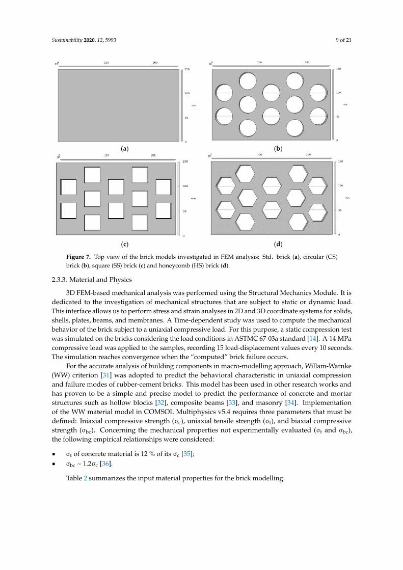
Three types of vertically perforated bricks were modelled, all of them with the same dimension(250 mm × 150 mm × 40 mm). Hollow samples have the same number of holes (12) arranged in adouble-hexagonal array. Circular (CS brick), square (SS brick), and “honeycomb” (HS brick) cavityshapes were investigated. The holes size was optimized to ensure the same perforation degree ineach model (40%). In CS bricks, the cavity radius is 13 mm. In SS bricks, the square side is 33 mm.In HS bricks, the hexagon side in 20.5 mm. To evaluate the effect of the perforated structure on themechanical behavior of the brick, the unperforated block (Std.) was also investigated. The geometriesof models for solid and hollow bricks are shown in Figure 7.
Sustainability 2020, 12, 5993 9 of 21
Sustainability 2020, 12, x FOR PEER REVIEW 9 of 21
(a) (b)
(c) (d)
Figure 7. Top view of the brick models investigated in FEM analysis: Std. brick (a), circular (CS) brick (b), square (SS) brick (c) and honeycomb (HS) brick (d).
2.3.3. Material and Physics
3D FEM-based mechanical analysis was performed using the Structural Mechanics Module. It is dedicated to the investigation of mechanical structures that are subject to static or dynamic load. This interface allows us to perform stress and strain analyses in 2D and 3D coordinate systems for solids, shells, plates, beams, and membranes. A Time-dependent study was used to compute the mechanical behavior of the brick subject to a uniaxial compressive load. For this purpose, a static compression test was simulated on the bricks considering the load conditions in ASTMC 67-03a standard [14]. A 14 MPa compressive load was applied to the samples, recording 15 load-displacement values every 10 seconds. The simulation reaches convergence when the “computed” brick failure occurs.
For the accurate analysis of building components in macro-modelling approach, Willam-Warnke (WW) criterion [31] was adopted to predict the behavioral characteristic in uniaxial compression and failure modes of rubber-cement bricks. This model has been used in other research works and has proven to be a simple and precise model to predict the performance of concrete and mortar structures such as hollow blocks [32], composite beams [33], and masonry [34]. Implementation of the WW material model in COMSOL Multiphysics v5.4 requires three parameters that must be defined: Iniaxial compressive strength (σc), uniaxial tensile strength (σt), and biaxial compressive strength (σbc). Concerning the mechanical properties not experimentally evaluated (σt
and σbc), the following empirical relationships were considered: • σt of concrete material is 12 % of its σc [35]; • σbc ~ 1.2σc [36]. Table 2 summarizes the input material properties for the brick modelling.
Table 2. Input material properties for FEM-based mechanical analysis.
Material Property Symbol Property group Evaluation Density ρ Basic Experimental Porosity P Basic Experimental
Young’s modulus E Basic Experimental
Figure 7. Top view of the brick models investigated in FEM analysis: Std. brick (a), circular (CS)brick (b), square (SS) brick (c) and honeycomb (HS) brick (d).
2.3.3. Material and Physics
3D FEM-based mechanical analysis was performed using the Structural Mechanics Module. It isdedicated to the investigation of mechanical structures that are subject to static or dynamic load.This interface allows us to perform stress and strain analyses in 2D and 3D coordinate systems for solids,shells, plates, beams, and membranes. A Time-dependent study was used to compute the mechanicalbehavior of the brick subject to a uniaxial compressive load. For this purpose, a static compression testwas simulated on the bricks considering the load conditions in ASTMC 67-03a standard [14]. A 14 MPacompressive load was applied to the samples, recording 15 load-displacement values every 10 seconds.The simulation reaches convergence when the “computed” brick failure occurs.
For the accurate analysis of building components in macro-modelling approach, Willam-Warnke(WW) criterion [31] was adopted to predict the behavioral characteristic in uniaxial compressionand failure modes of rubber-cement bricks. This model has been used in other research works andhas proven to be a simple and precise model to predict the performance of concrete and mortarstructures such as hollow blocks [32], composite beams [33], and masonry [34]. Implementationof the WW material model in COMSOL Multiphysics v5.4 requires three parameters that must bedefined: Iniaxial compressive strength (σc), uniaxial tensile strength (σt), and biaxial compressivestrength (σbc). Concerning the mechanical properties not experimentally evaluated (σt and σbc),the following empirical relationships were considered:
• σt of concrete material is 12 % of its σc [35];• σbc ~ 1.2σc [36].
Table 2 summarizes the input material properties for the brick modelling.

Sustainability 2020, 12, 5993 10 of 21
Table 2. Input material properties for FEM-based mechanical analysis.
Material Property Symbol Property Group Evaluation
Density ρ Basic ExperimentalPorosity P Basic Experimental
Young’s modulus E Basic ExperimentalUniaxial compressive strength σc Basic/WW criterion Experimental
Uniaxial tensile strength σt WW criterion EmpiricalBiaxial compressive strength σbc WW criterion Empirical
2.3.4. Mesh and Boundary Conditions
Each model was assumed to be subjected to axial compressive load, as shown in Figure 8a.“Boundary load” condition was applied to the upper side of the brick. The load type is a pressureof 14 MPa. The bottom side was assumed fixed by setting “Prescribed displacement” equal to 0in z directions. This assumption neglects the possible friction effect between the sample and thehypothetical support plane. A “free” boundary condition was selected for the other brick surfaces.A tetrahedral physics-controlled mesh (see Figure 8b) was used for the computational analysis. A “fine”element size was choice for mesh discretization in order to obtain a good compromise among resultsaccuracy and computational power.
Sustainability 2020, 12, x FOR PEER REVIEW 10 of 21
Uniaxial compressive strength σc Basic/WW criterion Experimental Uniaxial tensile strength σt WW criterion Empirical
Biaxial compressive strength σbc WW criterion Empirical
2.3.4. Mesh and Boundary Conditions
Each model was assumed to be subjected to axial compressive load, as shown in Figure 8a. “Boundary load” condition was applied to the upper side of the brick. The load type is a pressure of 14 MPa. The bottom side was assumed fixed by setting “Prescribed displacement” equal to 0 in z directions. This assumption neglects the possible friction effect between the sample and the hypothetical support plane. A “free” boundary condition was selected for the other brick surfaces. A tetrahedral physics-controlled mesh (see Figure 8b) was used for the computational analysis. A “fine” element size was choice for mesh discretization in order to obtain a good compromise among results accuracy and computational power.
(a) (b)
Figure 8. Applied load and boundary conditions (a) and mesh discretization of the model (b).
3. Results
3.1. Physical Characterization: Bulk Density and Permeable Porosity
Figure 9 shows the test results of bulk density and permeable porosity. The bulk density of mortars mixed with crumb rubber was found to decrease with the rubber content compared to control mix. Since the specific gravity of rubber aggregates is less than that of mineral ones, the sand-rubber replacement implied a reduction in dry unit weight [37,38]. The polymer finest fraction (rubber powder) had a more pronounced effect on material density. When comparing with control sample (1927 kg/m3), the bulk density value of P100 mix was lower about 30%, while the percentage decrease of P-G50/50 was about 16%. The hydrophobic nature of rubber promotes the air entrapment during the mixing process of fresh material, resulting in a higher air content than the “neat” mortar. The amount of entrained air increases with decreased particle size. Rubber powder has a greater specific surface than rubber granules, so its capability to adsorb gas is most relevant [39]. Moreover, the unit weight discrepancy between the investigated rubber-cement mixes is also attributable to the overall amount of rubber incorporated into the material. In P100 mix, the total replacement of mineral aggregates with the fine polymeric fraction implies a greater number of polymer particles per unit volume than the “combined” P-G50/50 mix, resulting in a more relevant bulk density reduction. Bulk density values are typical for lightweight mortars and correspond to a RILEM class II [40] lightweight cementitious materials (oven-dry density less than 2000 kg/m3). These class of cement mixtures is generally used to reduce the dead weight of a structure and to improve the thermal insulation requirements in building applications [41].
Permeable porosity indicates the ease with which fluids and gas can penetrate and move through the cement material and it is, therefore, a good indicator of its durability. Besides, the voids fraction affects the mechanical strength of the hardened compound [42,43]. However, by promoting a certain porosity degree, the acoustic functionality of the material is enhanced. Several studies
Figure 8. Applied load and boundary conditions (a) and mesh discretization of the model (b).
3. Results
3.1. Physical Characterization: Bulk Density and Permeable Porosity
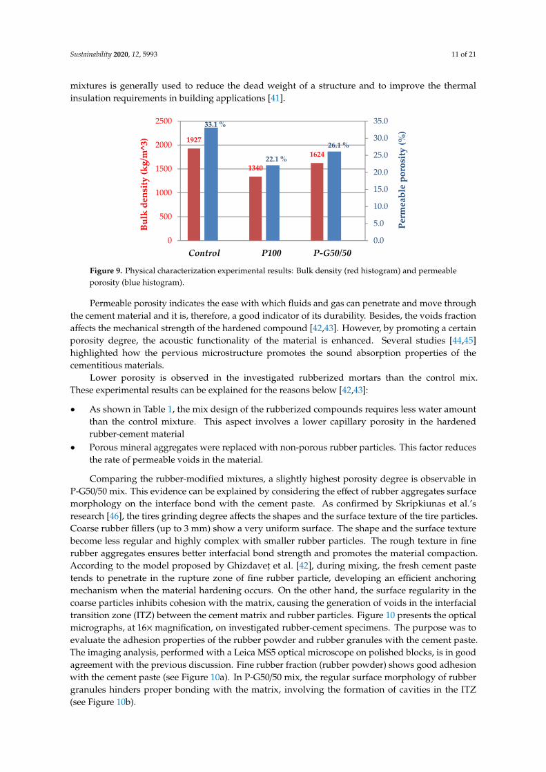
Figure 9 shows the test results of bulk density and permeable porosity. The bulk densityof mortars mixed with crumb rubber was found to decrease with the rubber content comparedto control mix. Since the specific gravity of rubber aggregates is less than that of mineral ones,the sand-rubber replacement implied a reduction in dry unit weight [37,38]. The polymer finest fraction(rubber powder) had a more pronounced effect on material density. When comparing with controlsample (1927 kg/m3), the bulk density value of P100 mix was lower about 30%, while the percentagedecrease of P-G50/50 was about 16%. The hydrophobic nature of rubber promotes the air entrapmentduring the mixing process of fresh material, resulting in a higher air content than the “neat” mortar.The amount of entrained air increases with decreased particle size. Rubber powder has a greaterspecific surface than rubber granules, so its capability to adsorb gas is most relevant [39]. Moreover,the unit weight discrepancy between the investigated rubber-cement mixes is also attributable tothe overall amount of rubber incorporated into the material. In P100 mix, the total replacement ofmineral aggregates with the fine polymeric fraction implies a greater number of polymer particles perunit volume than the “combined” P-G50/50 mix, resulting in a more relevant bulk density reduction.Bulk density values are typical for lightweight mortars and correspond to a RILEM class II [40]lightweight cementitious materials (oven-dry density less than 2000 kg/m3). These class of cement
Sustainability 2020, 12, 5993 11 of 21
mixtures is generally used to reduce the dead weight of a structure and to improve the thermalinsulation requirements in building applications [41].
Sustainability 2020, 12, x FOR PEER REVIEW 11 of 21
[44,45] highlighted how the pervious microstructure promotes the sound absorption properties of the cementitious materials.
Lower porosity is observed in the investigated rubberized mortars than the control mix. These experimental results can be explained for the reasons below [42,43]:
• As shown in Table 1, the mix design of the rubberized compounds requires less water amount than the control mixture. This aspect involves a lower capillary porosity in the hardened rubber-cement material
• Porous mineral aggregates were replaced with non-porous rubber particles. This factor reduces the rate of permeable voids in the material
Figure 9. Physical characterization experimental results: Bulk density (red histogram) and permeable porosity (blue histogram).
Comparing the rubber-modified mixtures, a slightly highest porosity degree is observable in P-G50/50 mix. This evidence can be explained by considering the effect of rubber aggregates surface morphology on the interface bond with the cement paste. As confirmed by Skripkiunas et al.’s research [46], the tires grinding degree affects the shapes and the surface texture of the tire particles. Coarse rubber fillers (up to 3 mm) show a very uniform surface. The shape and the surface texture become less regular and highly complex with smaller rubber particles. The rough texture in fine rubber aggregates ensures better interfacial bond strength and promotes the material compaction. According to the model proposed by Ghizdaveț et al. [42], during mixing, the fresh cement paste tends to penetrate in the rupture zone of fine rubber particle, developing an efficient anchoring mechanism when the material hardening occurs. On the other hand, the surface regularity in the coarse particles inhibits cohesion with the matrix, causing the generation of voids in the interfacial transition zone (ITZ) between the cement matrix and rubber particles. Figure 10 presents the optical micrographs, at 16x magnification, on investigated rubber-cement specimens. The purpose was to evaluate the adhesion properties of the rubber powder and rubber granules with the cement paste. The imaging analysis, performed with a Leica MS5 optical microscope on polished blocks, is in good agreement with the previous discussion. Fine rubber fraction (rubber powder) shows good adhesion with the cement paste (see Figure 10a). In P-G50/50 mix, the regular surface morphology of rubber granules hinders proper bonding with the matrix, involving the formation of cavities in the ITZ (see Figure 10b).
1927
1340
1624
33.1 %
22.1 %
26.1 %
0.0
5.0
10.0
15.0
20.0
25.0
30.0
35.0
0
500
1000
1500
2000
2500
Perm
eabl
e po
rosi
ty (%
)
Bulk
den
sity
(kg/
m^3
)
Control P100 P-G50/50
Figure 9. Physical characterization experimental results: Bulk density (red histogram) and permeableporosity (blue histogram).
Permeable porosity indicates the ease with which fluids and gas can penetrate and move throughthe cement material and it is, therefore, a good indicator of its durability. Besides, the voids fractionaffects the mechanical strength of the hardened compound [42,43]. However, by promoting a certainporosity degree, the acoustic functionality of the material is enhanced. Several studies [44,45]highlighted how the pervious microstructure promotes the sound absorption properties of thecementitious materials.
Lower porosity is observed in the investigated rubberized mortars than the control mix.These experimental results can be explained for the reasons below [42,43]:
• As shown in Table 1, the mix design of the rubberized compounds requires less water amountthan the control mixture. This aspect involves a lower capillary porosity in the hardenedrubber-cement material
• Porous mineral aggregates were replaced with non-porous rubber particles. This factor reducesthe rate of permeable voids in the material.
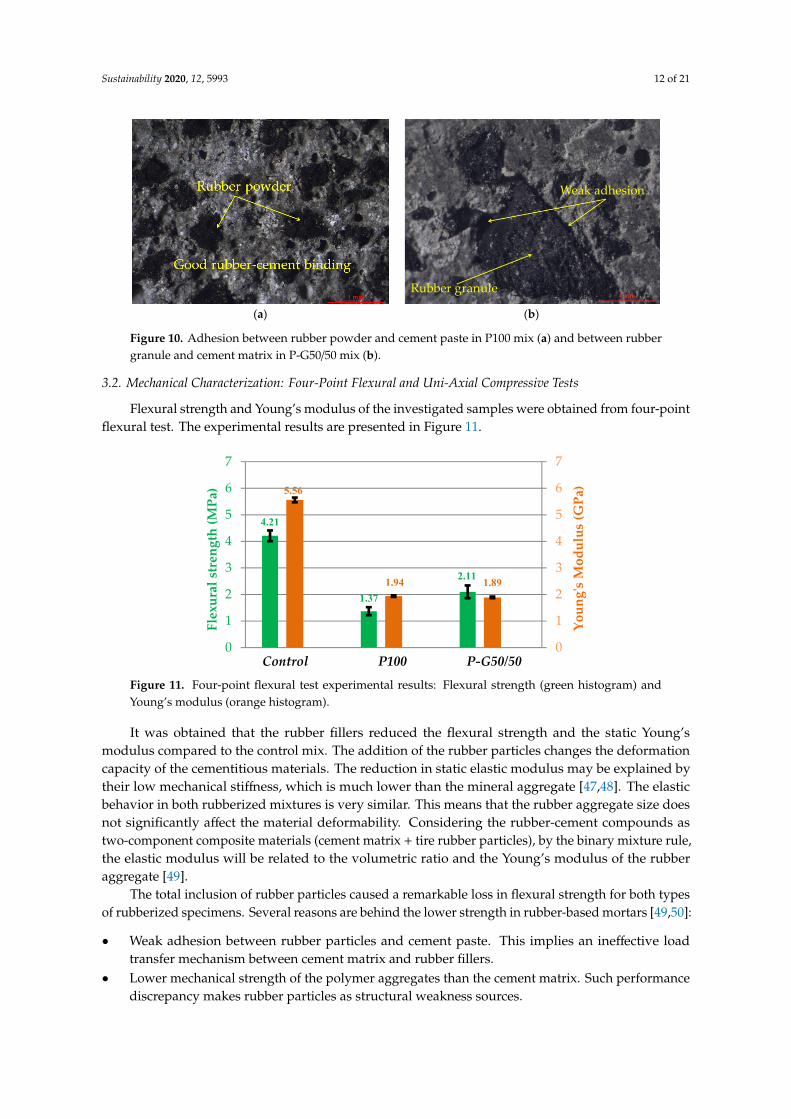
Comparing the rubber-modified mixtures, a slightly highest porosity degree is observable inP-G50/50 mix. This evidence can be explained by considering the effect of rubber aggregates surfacemorphology on the interface bond with the cement paste. As confirmed by Skripkiunas et al.’sresearch [46], the tires grinding degree affects the shapes and the surface texture of the tire particles.Coarse rubber fillers (up to 3 mm) show a very uniform surface. The shape and the surface texturebecome less regular and highly complex with smaller rubber particles. The rough texture in finerubber aggregates ensures better interfacial bond strength and promotes the material compaction.According to the model proposed by Ghizdavet, et al. [42], during mixing, the fresh cement pastetends to penetrate in the rupture zone of fine rubber particle, developing an efficient anchoringmechanism when the material hardening occurs. On the other hand, the surface regularity in thecoarse particles inhibits cohesion with the matrix, causing the generation of voids in the interfacialtransition zone (ITZ) between the cement matrix and rubber particles. Figure 10 presents the opticalmicrographs, at 16×magnification, on investigated rubber-cement specimens. The purpose was toevaluate the adhesion properties of the rubber powder and rubber granules with the cement paste.The imaging analysis, performed with a Leica MS5 optical microscope on polished blocks, is in goodagreement with the previous discussion. Fine rubber fraction (rubber powder) shows good adhesionwith the cement paste (see Figure 10a). In P-G50/50 mix, the regular surface morphology of rubbergranules hinders proper bonding with the matrix, involving the formation of cavities in the ITZ(see Figure 10b).
Sustainability 2020, 12, 5993 12 of 21
Sustainability 2020, 12, x FOR PEER REVIEW 12 of 21
(a) (b)
Figure 10. Adhesion between rubber powder and cement paste in P100 mix (a) and between rubber granule and cement matrix in P-G50/50 mix (b).
3.2. Mechanical Characterization: Four-Point Flexural and Uni-Axial Compressive Tests
Flexural strength and Young’s modulus of the investigated samples were obtained from four-point flexural test. The experimental results are presented in Figure 11.
Figure 11. Four-point flexural test experimental results: Flexural strength (green histogram) and Young’s modulus (orange histogram).
It was obtained that the rubber fillers reduced the flexural strength and the static Young’s modulus compared to the control mix. The addition of the rubber particles changes the deformation capacity of the cementitious materials. The reduction in static elastic modulus may be explained by their low mechanical stiffness, which is much lower than the mineral aggregate [47,48]. The elastic behavior in both rubberized mixtures is very similar. This means that the rubber aggregate size does not significantly affect the material deformability. Considering the rubber-cement compounds as two-component composite materials (cement matrix + tire rubber particles), by the binary mixture rule, the elastic modulus will be related to the volumetric ratio and the Young’s modulus of the rubber aggregate [49].
The total inclusion of rubber particles caused a remarkable loss in flexural strength for both types of rubberized specimens. Several reasons are behind the lower strength in rubber-based mortars [49,50]:
• Weak adhesion between rubber particles and cement paste. This implies an ineffective load transfer mechanism between cement matrix and rubber fillers.
• Lower mechanical strength of the polymer aggregates than the cement matrix. Such performance discrepancy makes rubber particles as structural weakness sources.
4.21
1.37
2.11
5.56
1.94 1.89
0
1
2
3
4
5
6
7
0
1
2
3
4
5
6
7
Flex
ural
str
engt
h (M
Pa)
Youn
g's
Mod
ulus
(GPa
)
Control P100 P-G50/50
Figure 10. Adhesion between rubber powder and cement paste in P100 mix (a) and between rubbergranule and cement matrix in P-G50/50 mix (b).
3.2. Mechanical Characterization: Four-Point Flexural and Uni-Axial Compressive Tests
Flexural strength and Young’s modulus of the investigated samples were obtained from four-pointflexural test. The experimental results are presented in Figure 11.
Sustainability 2020, 12, x FOR PEER REVIEW 12 of 21
(a) (b)
Figure 10. Adhesion between rubber powder and cement paste in P100 mix (a) and between rubber granule and cement matrix in P-G50/50 mix (b).
3.2. Mechanical Characterization: Four-Point Flexural and Uni-Axial Compressive Tests
Flexural strength and Young’s modulus of the investigated samples were obtained from four-point flexural test. The experimental results are presented in Figure 11.
Figure 11. Four-point flexural test experimental results: Flexural strength (green histogram) and Young’s modulus (orange histogram).
It was obtained that the rubber fillers reduced the flexural strength and the static Young’s modulus compared to the control mix. The addition of the rubber particles changes the deformation capacity of the cementitious materials. The reduction in static elastic modulus may be explained by their low mechanical stiffness, which is much lower than the mineral aggregate [47,48]. The elastic behavior in both rubberized mixtures is very similar. This means that the rubber aggregate size does not significantly affect the material deformability. Considering the rubber-cement compounds as two-component composite materials (cement matrix + tire rubber particles), by the binary mixture rule, the elastic modulus will be related to the volumetric ratio and the Young’s modulus of the rubber aggregate [49].
The total inclusion of rubber particles caused a remarkable loss in flexural strength for both types of rubberized specimens. Several reasons are behind the lower strength in rubber-based mortars [49,50]:
• Weak adhesion between rubber particles and cement paste. This implies an ineffective load transfer mechanism between cement matrix and rubber fillers.
• Lower mechanical strength of the polymer aggregates than the cement matrix. Such performance discrepancy makes rubber particles as structural weakness sources.
4.21
1.37
2.11
5.56
1.94 1.89
0
1
2
3
4
5
6
7
0
1
2
3
4
5
6
7
Flex
ural
str
engt
h (M
Pa)
Youn
g's
Mod
ulus
(GPa
)
Control P100 P-G50/50
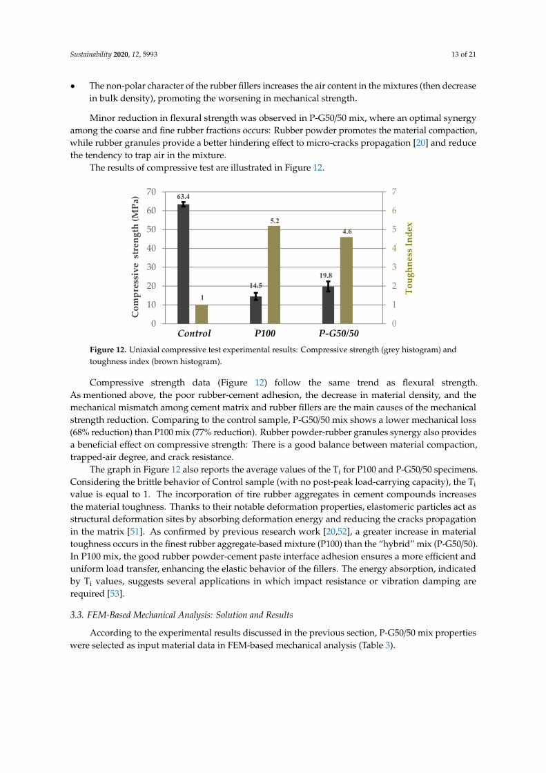
Figure 11. Four-point flexural test experimental results: Flexural strength (green histogram) andYoung’s modulus (orange histogram).
It was obtained that the rubber fillers reduced the flexural strength and the static Young’smodulus compared to the control mix. The addition of the rubber particles changes the deformationcapacity of the cementitious materials. The reduction in static elastic modulus may be explained bytheir low mechanical stiffness, which is much lower than the mineral aggregate [47,48]. The elasticbehavior in both rubberized mixtures is very similar. This means that the rubber aggregate size doesnot significantly affect the material deformability. Considering the rubber-cement compounds astwo-component composite materials (cement matrix + tire rubber particles), by the binary mixture rule,the elastic modulus will be related to the volumetric ratio and the Young’s modulus of the rubberaggregate [49].
The total inclusion of rubber particles caused a remarkable loss in flexural strength for both typesof rubberized specimens. Several reasons are behind the lower strength in rubber-based mortars [49,50]:
• Weak adhesion between rubber particles and cement paste. This implies an ineffective loadtransfer mechanism between cement matrix and rubber fillers.
• Lower mechanical strength of the polymer aggregates than the cement matrix. Such performancediscrepancy makes rubber particles as structural weakness sources.
Sustainability 2020, 12, 5993 13 of 21
• The non-polar character of the rubber fillers increases the air content in the mixtures (then decreasein bulk density), promoting the worsening in mechanical strength.
Minor reduction in flexural strength was observed in P-G50/50 mix, where an optimal synergyamong the coarse and fine rubber fractions occurs: Rubber powder promotes the material compaction,while rubber granules provide a better hindering effect to micro-cracks propagation [20] and reducethe tendency to trap air in the mixture.
The results of compressive test are illustrated in Figure 12.
Sustainability 2020, 12, x FOR PEER REVIEW 13 of 21
• The non-polar character of the rubber fillers increases the air content in the mixtures (then decrease in bulk density), promoting the worsening in mechanical strength.
Minor reduction in flexural strength was observed in P-G50/50 mix, where an optimal synergy among the coarse and fine rubber fractions occurs: Rubber powder promotes the material compaction, while rubber granules provide a better hindering effect to micro-cracks propagation [20] and reduce the tendency to trap air in the mixture.
The results of compressive test are illustrated in Figure 12.
Figure 12. Uniaxial compressive test experimental results: Compressive strength (grey histogram) and toughness index (brown histogram).
Compressive strength data (Figure 12) follow the same trend as flexural strength. As mentioned above, the poor rubber-cement adhesion, the decrease in material density, and the mechanical mismatch among cement matrix and rubber fillers are the main causes of the mechanical strength reduction. Comparing to the control sample, P-G50/50 mix shows a lower mechanical loss (68 % reduction) than P100 mix (77% reduction). Rubber powder-rubber granules synergy also provides a beneficial effect on compressive strength: There is a good balance between material compaction, trapped-air degree, and crack resistance.
The graph in Figure 12 also reports the average values of the Ti for P100 and P-G50/50 specimens. Considering the brittle behavior of Control sample (with no post-peak load-carrying capacity), the Ti value is equal to 1. The incorporation of tire rubber aggregates in cement compounds increases the material toughness. Thanks to their notable deformation properties, elastomeric particles act as structural deformation sites by absorbing deformation energy and reducing the cracks propagation in the matrix [51]. As confirmed by previous research work [20,52], a greater increase in material toughness occurs in the finest rubber aggregate-based mixture (P100) than the “hybrid” mix (P-G50/50). In P100 mix, the good rubber powder-cement paste interface adhesion ensures a more efficient and uniform load transfer, enhancing the elastic behavior of the fillers. The energy absorption, indicated by Ti values, suggests several applications in which impact resistance or vibration damping are required [53].
3.3. FEM-Based Mechanical Analysis: Solution and Results
According to the experimental results discussed in the previous section, P-G50/50 mix properties were selected as input material data in FEM-based mechanical analysis (Table 3).
Table 3. P-G5/50 mix properties for FEM-based mechanical analysis.
Material Property Symbol Value Property group Evaluation Density ρ 1624 kg/m3 Basic Experimental Porosity P 0.261 Basic Experimental
Young’s modulus E 1.89 GPa Basic Experimental
63.4
14.519.8
1
5.24.6
0
1
2
3
4
5
6
7
0
10
20
30
40
50
60
70
Com
pres
sive
str
engt
h (M
Pa)
Toug
hnes
s In
dex
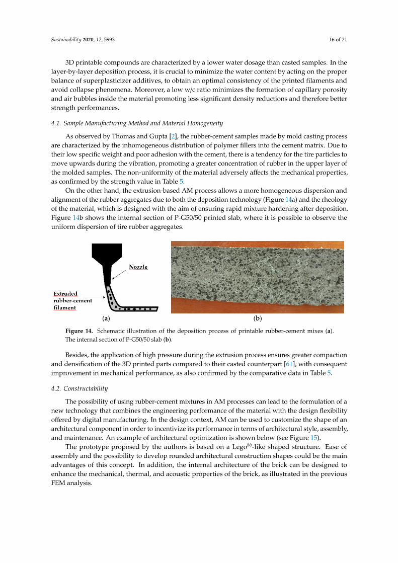
Control P100 P-G50/50 Figure 12. Uniaxial compressive test experimental results: Compressive strength (grey histogram) andtoughness index (brown histogram).
Compressive strength data (Figure 12) follow the same trend as flexural strength.As mentioned above, the poor rubber-cement adhesion, the decrease in material density, and themechanical mismatch among cement matrix and rubber fillers are the main causes of the mechanicalstrength reduction. Comparing to the control sample, P-G50/50 mix shows a lower mechanical loss(68% reduction) than P100 mix (77% reduction). Rubber powder-rubber granules synergy also providesa beneficial effect on compressive strength: There is a good balance between material compaction,trapped-air degree, and crack resistance.
The graph in Figure 12 also reports the average values of the Ti for P100 and P-G50/50 specimens.Considering the brittle behavior of Control sample (with no post-peak load-carrying capacity), the Ti
value is equal to 1. The incorporation of tire rubber aggregates in cement compounds increasesthe material toughness. Thanks to their notable deformation properties, elastomeric particles act asstructural deformation sites by absorbing deformation energy and reducing the cracks propagationin the matrix [51]. As confirmed by previous research work [20,52], a greater increase in materialtoughness occurs in the finest rubber aggregate-based mixture (P100) than the “hybrid” mix (P-G50/50).In P100 mix, the good rubber powder-cement paste interface adhesion ensures a more efficient anduniform load transfer, enhancing the elastic behavior of the fillers. The energy absorption, indicatedby Ti values, suggests several applications in which impact resistance or vibration damping arerequired [53].
3.3. FEM-Based Mechanical Analysis: Solution and Results
According to the experimental results discussed in the previous section, P-G50/50 mix propertieswere selected as input material data in FEM-based mechanical analysis (Table 3).

Sustainability 2020, 12, 5993 14 of 21
Table 3. P-G5/50 mix properties for FEM-based mechanical analysis.
Material Property Symbol Value Property Group Evaluation
Density ρ 1624 kg/m3 Basic ExperimentalPorosity P 0.261 Basic Experimental
Young’s modulus E 1.89 GPa Basic ExperimentalUniaxial compressive strength σc 19.8 MPa Basic/WW criterion Experimental
Uniaxial tensile strength σt 2.38 MPa WW criterion EmpiricalBiaxial compressive strength σbc 23.8 MPa WW criterion Empirical
Numerical load-displacement curves were analyzed to extrapolate the mechanical propertiesof each type of brick design investigated in this work. Table 4 shows the comparison of σc and Evalues for the four proposed model. Comparing the mechanical strength of perforated bricks, CS,and HS designs offer the best result in terms of compressive strength. However, as previously reported,the “honeycomb” geometries have a remarkable thermal and acoustic functionality, therefore havemore attractive requirements for building applications.
Table 4. FEM-based mechanical analysis: Numerical results.
Brick Design σc (MPa) StrengthReduction Rate E (GPa) Young’s Modulus
Reduction Rate
Std. brick 21.2 - 1.87 -CS brick 15.1 28.8% 1.22 34.8%SS brick 13.4 36.8% 1.22 34.8%HS brick 15.0 29.2% 1.21 35.3%
According to FEM analysis results, the rubber-cement mixture and the brick designs selectedare all potentially suitable for the fabrication of load-bearing units. In this context, ASTM C90 [54]standards require minimum compressive strengths of 7.0 MPa and 11.7 MPa. As confirmed bythe research mentioned in Section 2.3, perforated bricks show relevant stiffness reduction (~35%)compared to solid brick, due to a more favorable stresses distribution in the material. Cavity geometrydoesn’t significantly affect the elastic behavior, but has a noticeable effect on mechanical strengthreduction. Small curvature radii of square cavities (SS brick) act as mechanical weakness elements,where remarkable stress concentrations occur, and cracks are easily triggered in the material. Conversely,when the cavity geometry tends to circular shape (wide curvature radii), improved performances interms of compressive strength are observed. Figure 13 highlights the stress distribution comparisonbetween Std. and HS brick.
Sustainability 2020, 12, x FOR PEER REVIEW 14 of 21
Uniaxial compressive strength σc 19.8 MPa Basic/WW criterion Experimental Uniaxial tensile strength σt 2.38 MPa WW criterion Empirical
Biaxial compressive strength σbc 23.8 MPa WW criterion Empirical
Numerical load-displacement curves were analyzed to extrapolate the mechanical properties of each type of brick design investigated in this work. Table 4 shows the comparison of σc and E values for the four proposed model. Comparing the mechanical strength of perforated bricks, CS, and HS designs offer the best result in terms of compressive strength. However, as previously reported, the “honeycomb” geometries have a remarkable thermal and acoustic functionality, therefore have more attractive requirements for building applications.
Table 4. FEM-based mechanical analysis: Numerical results.
Brick design σc (MPa) Strength reduction rate E (GPa) Young’s modulus reduction rate
Std. brick 21.2 - 1.87 - CS brick 15.1 28.8% 1.22 34.8% SS brick 13.4 36.8% 1.22 34.8% HS brick 15.0 29.2% 1.21 35.3%
According to FEM analysis results, the rubber-cement mixture and the brick designs selected are all potentially suitable for the fabrication of load-bearing units. In this context, ASTM C90 [54] standards require minimum compressive strengths of 7.0 MPa and 11.7 MPa. As confirmed by the research mentioned in 2.3 section, perforated bricks show relevant stiffness reduction (~35%) compared to solid brick, due to a more favorable stresses distribution in the material. Cavity geometry doesn’t significantly affect the elastic behavior, but has a noticeable effect on mechanical strength reduction. Small curvature radii of square cavities (SS brick) act as mechanical weakness elements, where remarkable stress concentrations occur, and cracks are easily triggered in the material. Conversely, when the cavity geometry tends to circular shape (wide curvature radii), improved performances in terms of compressive strength are observed. Figure 13 highlights the stress distribution comparison between Std. and HS brick.
(a) (b)
Figure 13. Stress distribution in Std. brick (a) and HS brick (b).
The relatively high flexibility of these modeled prototypes suggests their potential use in applications where mechanical/acoustic damping and ductility are primary requirements (flexible brick paving, lightweight partition walls, architectural units for insulation purposes).
4. Comparative Analysis of Tire Rubber-Cement Compounds Made by Casted and 3D Printing Methods
Figure 13. Stress distribution in Std. brick (a) and HS brick (b).
The relatively high flexibility of these modeled prototypes suggests their potential use inapplications where mechanical/acoustic damping and ductility are primary requirements (flexiblebrick paving, lightweight partition walls, architectural units for insulation purposes).

Sustainability 2020, 12, 5993 15 of 21
4. Comparative Analysis of Tire Rubber-Cement Compounds Made by Casted and 3DPrinting Methods
The use of granulated waste tires in concrete materials has been widely studied in the last twentyyears as an eco-sustainable and functional solution in the civil and architectural fields. Besides savingnatural resources and recycling end-of-life tires, rubber-cement mixtures could represent a class ofbuilding materials with improved energy efficiency. The enhancement of energy efficiency in theconstruction sector is one of the main challenges for a sustainable requalification of energy issues and aconsequent favorable economic–environmental impact [55]. In this framework, the peculiarities of tirerubber-modified cementitious materials are attributable to the following aspects:
• Lightweight: The low density of rubberized mortars enables reduction dead-weight of structuresand dimensions of building components (façade panels, slabs, block, non-structural elements).Weight reduction may reduce pre-cast elements transportation costs (less expensive handling andtransporting equipment) as well as provide slender and spacious construction [56].
• Thermal insulation: The use of tire rubber in lightweight mortar allows the production of buildingmaterials with improved thermal efficiency. Pelisser et al. [57] evaluated the thermal performancesof mortar panels, mainly for use in facades and signs. The addition of rubber aggregates gave thecomponent a 15% higher thermal resistance than the standard material. This improved thermalinsulation feature contributes to the achievement of energy efficiency, reducing operating coststhrough lower energy consumption.
• Vibroacoustic insulation: Lightweight rubber-cement mortars can be used for acoustic performancequalification in buildings for the impact and airborne noises. Concerning the sound transmissionthrough a structure, rigid partitions that deform slightly before the vibration transmit the soundwaves in a very short time. Elastomeric properties of tire rubber aggregates improve the materialdeformability, promoting the sound attenuation. Tutikian et al. [58] showed that the totalreplacement of mineral aggregates with polymeric aggregates results in an impact noise reductionof up to 15 dB.
• However, the possibility of using these compounds in AM methods represents an advancedtechnological upgrade. Preliminary comparison between the features of printable and castedrubberized mixes highlights some interesting effects brought by 3D printing, which can be keypoints in state-of-the-art context.
• Material rheology and physical-mechanical properties.
As mentioned in Section 2.1, the mix design of printable mixes must meet specific requirements:They must be extruded and support their shape without deformation or interruption. For this reason,the rheology of printable rubber-cement mixes is different from that of traditional ones, influencingthe mechanical and microstructural properties of the hardened material. Table 5 shows acomprehensive comparison between the properties of some casted rubber-cement mixtures (deductedby literature research) and the 3D printable compounds proposed in this work. For a coherentcomparative analysis, the literature data refer to rubberized mixes obtained by total mineralaggregates-tire rubber replacement.
Table 5. Rheological and physical-mechanical properties of casted and printed rubber-cement compounds.
Sample Type w/c Ratio Density (kg/m3) Compressive Strength (MPa)
Casted [20] 0.770 <1300 <1Casted [59] 0.520 1300 1.5Casted [60] 0.350 1321 7.1
Printed (P100) 0.325 1340 14.5Printed (P-G50/50) 0.312 1624 19.8
Sustainability 2020, 12, 5993 16 of 21
3D printable compounds are characterized by a lower water dosage than casted samples. In thelayer-by-layer deposition process, it is crucial to minimize the water content by acting on the properbalance of superplasticizer additives, to obtain an optimal consistency of the printed filaments andavoid collapse phenomena. Moreover, a low w/c ratio minimizes the formation of capillary porosityand air bubbles inside the material promoting less significant density reductions and therefore betterstrength performances.
4.1. Sample Manufacturing Method and Material Homogeneity
As observed by Thomas and Gupta [2], the rubber-cement samples made by mold casting processare characterized by the inhomogeneous distribution of polymer fillers into the cement matrix. Due totheir low specific weight and poor adhesion with the cement, there is a tendency for the tire particles tomove upwards during the vibration, promoting a greater concentration of rubber in the upper layer ofthe molded samples. The non-uniformity of the material adversely affects the mechanical properties,as confirmed by the strength value in Table 5.
On the other hand, the extrusion-based AM process allows a more homogeneous dispersion andalignment of the rubber aggregates due to both the deposition technology (Figure 14a) and the rheologyof the material, which is designed with the aim of ensuring rapid mixture hardening after deposition.Figure 14b shows the internal section of P-G50/50 printed slab, where it is possible to observe theuniform dispersion of tire rubber aggregates.
Sustainability 2020, 12, x FOR PEER REVIEW 16 of 21
balance of superplasticizer additives, to obtain an optimal consistency of the printed filaments and avoid collapse phenomena. Moreover, a low w/c ratio minimizes the formation of capillary porosity and air bubbles inside the material promoting less significant density reductions and therefore better strength performances.
4.1. Sample Manufacturing Method and Material Homogeneity
As observed by Thomas and Gupta [2], the rubber-cement samples made by mold casting process are characterized by the inhomogeneous distribution of polymer fillers into the cement matrix. Due to their low specific weight and poor adhesion with the cement, there is a tendency for the tire particles to move upwards during the vibration, promoting a greater concentration of rubber in the upper layer of the molded samples. The non-uniformity of the material adversely affects the mechanical properties, as confirmed by the strength value in Table 5.
On the other hand, the extrusion-based AM process allows a more homogeneous dispersion and alignment of the rubber aggregates due to both the deposition technology (Figure 14a) and the rheology of the material, which is designed with the aim of ensuring rapid mixture hardening after deposition. Figure 14b shows the internal section of P-G50/50 printed slab, where it is possible to observe the uniform dispersion of tire rubber aggregates.
(a) (b)
Figure 14. Schematic illustration of the deposition process of printable rubber-cement mixes (a). The internal section of P-G50/50 slab (b).
Besides, the application of high pressure during the extrusion process ensures greater compaction and densification of the 3D printed parts compared to their casted counterpart [61], with consequent improvement in mechanical performance, as also confirmed by the comparative data in Table 5.
4.2. Constructability
The possibility of using rubber-cement mixtures in AM processes can lead to the formulation of a new technology that combines the engineering performance of the material with the design flexibility offered by digital manufacturing. In the design context, AM can be used to customize the shape of an architectural component in order to incentivize its performance in terms of architectural style, assembly, and maintenance. An example of architectural optimization is shown below (see Figure 15).
Figure 14. Schematic illustration of the deposition process of printable rubber-cement mixes (a).The internal section of P-G50/50 slab (b).
Besides, the application of high pressure during the extrusion process ensures greater compactionand densification of the 3D printed parts compared to their casted counterpart [61], with consequentimprovement in mechanical performance, as also confirmed by the comparative data in Table 5.
4.2. Constructability
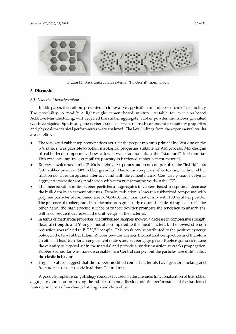
The possibility of using rubber-cement mixtures in AM processes can lead to the formulation of anew technology that combines the engineering performance of the material with the design flexibilityoffered by digital manufacturing. In the design context, AM can be used to customize the shape of anarchitectural component in order to incentivize its performance in terms of architectural style, assembly,and maintenance. An example of architectural optimization is shown below (see Figure 15).
The prototype proposed by the authors is based on a Lego®-like shaped structure. Ease ofassembly and the possibility to develop rounded architectural construction shapes could be the mainadvantages of this concept. In addition, the internal architecture of the brick can be designed toenhance the mechanical, thermal, and acoustic properties of the brick, as illustrated in the previousFEM analysis.
Sustainability 2020, 12, 5993 17 of 21
Sustainability 2020, 12, x FOR PEER REVIEW 16 of 21
balance of superplasticizer additives, to obtain an optimal consistency of the printed filaments and avoid collapse phenomena. Moreover, a low w/c ratio minimizes the formation of capillary porosity and air bubbles inside the material promoting less significant density reductions and therefore better strength performances.
4.1. Sample Manufacturing Method and Material Homogeneity
As observed by Thomas and Gupta [2], the rubber-cement samples made by mold casting process are characterized by the inhomogeneous distribution of polymer fillers into the cement matrix. Due to their low specific weight and poor adhesion with the cement, there is a tendency for the tire particles to move upwards during the vibration, promoting a greater concentration of rubber in the upper layer of the molded samples. The non-uniformity of the material adversely affects the mechanical properties, as confirmed by the strength value in Table 5.
On the other hand, the extrusion-based AM process allows a more homogeneous dispersion and alignment of the rubber aggregates due to both the deposition technology (Figure 14a) and the rheology of the material, which is designed with the aim of ensuring rapid mixture hardening after deposition. Figure 14b shows the internal section of P-G50/50 printed slab, where it is possible to observe the uniform dispersion of tire rubber aggregates.
(a) (b)
Figure 14. Schematic illustration of the deposition process of printable rubber-cement mixes (a). The internal section of P-G50/50 slab (b).
Besides, the application of high pressure during the extrusion process ensures greater compaction and densification of the 3D printed parts compared to their casted counterpart [61], with consequent improvement in mechanical performance, as also confirmed by the comparative data in Table 5.
4.2. Constructability
The possibility of using rubber-cement mixtures in AM processes can lead to the formulation of a new technology that combines the engineering performance of the material with the design flexibility offered by digital manufacturing. In the design context, AM can be used to customize the shape of an architectural component in order to incentivize its performance in terms of architectural style, assembly, and maintenance. An example of architectural optimization is shown below (see Figure 15).
Figure 15. Brick concept with external “functional” morphology.
5. Discussion
5.1. Material Characterization
In this paper, the authors presented an innovative application of “rubber-concrete” technology.The possibility to modify a lightweight cement-based mixture, suitable for extrusion-basedAdditive Manufacturing, with recycled tire rubber aggregate (rubber powder and rubber granules)was investigated. Specifically, the rubber grain size effects on fresh compound printability propertiesand physical-mechanical performances were analyzed. The key findings from the experimental resultsare as follows:
• The total sand-rubber replacement does not alter the proper mixtures printability. Working on thew/c ratio, it was possible to obtain rheological properties suitable for AM process. Mix designsof rubberized compounds show a lower water amount than the “standard” fresh mortar.This evidence implies less capillary porosity in hardened rubber-cement material.
• Rubber powder-based mix (P100) is slightly less porous and more compact than the “hybrid” mix(50% rubber powder—50% rubber granules). Due to the complex surface texture, the fine rubberfraction develops an optimal interface bond with the cement matrix. Conversely, coarse polymeraggregates provide weaker adhesion with cement, promoting voids in the ITZ.
• The incorporation of tire rubber particles as aggregates in cement-based compounds decreasethe bulk density in cement mixtures. Density reduction is lower in rubberized compound withpolymer particles of combined sizes (P-G50/50 mix) than that of mix with 100% rubber powder.The presence of rubber granules in the mixture significantly reduces the rate of trapped air. On theother hand, the high specific surface of rubber powder promotes the tendency to absorb gas,with a consequent decrease in the unit weight of the material.
• In terms of mechanical properties, the rubberized samples showed a decrease in compressive strength,flexural strength, and Young’s modulus compared to the “neat” material. The lowest strengthreduction was related to P-G50/50 sample. This result can be attributed to the positive synergybetween the two rubber fillers. Rubber powder ensures the material compaction and thereforean efficient load transfer among cement matrix and rubber aggregates. Rubber granules reducethe quantity of trapped air in the material and provide a hindering action to cracks propagation.Rubberized mortar was more deformable than Control sample, but the particles size didn’t affectthe elastic behavior.
• High Ti values suggest that the rubber-modified cement materials have greater cracking andfracture resistance to static load than Control mix.
A possible implementing strategy could be focused on the chemical functionalization of tire rubberaggregates aimed at improving the rubber-cement adhesion and the performance of the hardenedmaterial in terms of mechanical strength and durability.
Sustainability 2020, 12, 5993 18 of 21
5.2. FEM-Based Mechanical Analysis
This piece of research presents an innovative approach in the modeling and structural optimizationof rubber-cement mortars. FEM analysis is a very versatile tool for the study and physical-mechanicaloptimization of structures and building components. In this context, a numerical analysis wasperformed to investigate the effect of inner design on the mechanical properties of a rubber-cement brick.According to literature studies and the numerical results, it has been possible to deduce that the“honeycomb” perforated structure provides attractive performances in terms of mechanical flexibility,thermal insulation, and acoustic damping. The present analysis is a preliminary approach to this typeof experimentation. Obviously, additional FEM-based multi-physics studies will be needed to evaluatefurther functional design, investigate a wider range of engineering requirements, and validate thenumerical results with laboratory tests on real prototypes.
5.3. Casted and Printed Rubber-Cement Compounds: Comparative Analysis
The applicability of “rubber-concrete” technology to AM is an innovative topic in the constructionand civil fields. Although the functional properties of tire rubber-modified cementitious materialsare well known, the advantages that digital manufacturing can bring to the material are still to beexplored. However, a preliminary comparative analysis between casted and 3D printed materials waspresented in this work. The rheology of the printable materials combined with the deposition methodwould make it possible to obtain more homogeneous and compact samples with higher mechanicalproperties than traditional ones. Furthermore, the design flexibility of 3D printing would allow moresophisticated structural optimization studies aimed at improving the engineering and architecturalperformances of potential rubber-cement building elements.
6. Conclusions
The paper proposes an extensive research activity on novel rubber-cement mortars suitable forAM technologies.
First, the physical–mechanical properties of printable rubberized mixtures, obtained by totalreplacement of the sand with two tire crumb rubber fractions, were studied. The presence of thedouble polymer grain size in the mixture ensures lower loss in mechanical strength compared to theneat cementitious material, maintaining satisfactory deformability, toughness, and porosity properties.Besides, digital manufacturing provides mixture rheology and a deposition process which ensures amore compact, homogeneous material with greater mechanical strength properties than casted samples.However future research will be aimed at optimizing these cementitious compounds in terms ofincreasing rubber-cement compatibility.
A potential building application of these mixtures as functional hollow bricks was also reported.FEM-based mechanical analysis was performed to evaluate the mechanical performances of differentinternal designs. “Honeycomb”-shaped holes would seem to provide the best functionality in terms ofmechanical properties (as confirmed by FEM results) and thermo-acoustic performances (as deducedfrom literature studies). Rubberized compounds–AM compatibility will allow further studies toperformed on engineering attractive geometries, to obtain “bifunctional” elements, where a synergisticeffect between material properties and topological functionality occurs.
Author Contributions: Conceptualization, M.V. and M.S.; methodology, M.V., M.S. and A.S.; software, M.S.and A.S.; validation, M.V., M.S. and A.S.; formal analysis, M.V. and M.S.; investigation, M.S. and A.S.; resources,M.V. and E.M.; data curation, M.S. and A.S.; writing—original draft preparation, M.S. and A.S.; writing—reviewand editing, M.V. and E.M.; visualization, M.V. and E.M.; supervision, M.V.; project administration, M.V.;funding acquisition, M.V. and M.S. All authors have read and agreed to the published version of the manuscript.
Funding: This research was performed thanks to the Sapienza University direct financing for PhD student MatteoSambucci called “Avvio alla Ricerca”. Title is: “Study and optimization of rubber-concrete additives with recycledrubber that can be used through additive manufacturing: Optimization of thermo-acoustic, rheological andmechanical properties.”
Sustainability 2020, 12, 5993 19 of 21
Acknowledgments: The authors express their sincere gratitude to Valeria Corinaldesi and Eng. Glauco Merlonetti(Marche Polytechnic University) for their support in the additive manufacturing process. Besides, the authorswould like to thank Rocco Crescenzi (Sapienza University of Rome) for the concession of COMSOL workstation.
Conflicts of Interest: The authors declare no conflict of interest.
References
1. Purdue University Materials Engineering. Available online: https://engineering.purdue.edu/MSE/aboutus/whatsmaterials (accessed on 20 March 2020).
2. Thomas, B.S.; Gupta, R.C. A comprehensive review on the applications of waste tire rubber in cementconcrete. Renew. Sustain. Energy Rev. 2016, 54, 1323–1333. [CrossRef]
3. Al-Tayeb, M.M.; Hamouda, H. Effect of superplasticizer on workability of concrete containing crumb rubber.Civ. Environ. Res. 2015, 7, 35–43.
4. Son, K.S.; Hajirasouliha, I.; Pilakoutas, K. Strength and deformability of waste tyre rubber-filled reinforcedconcrete columns. Constr. Build. Mater. 2011, 25, 218–226. [CrossRef]
5. Chou, L.H.; Lu, C.K.; Chang, J.R.; Lee, M.T. Use of waste rubber as concrete additive. Waste Manag. Res.2007, 25, 68–76. [CrossRef] [PubMed]
6. El-Sherbini, Y.; Abdel-Gawad, A.K.; Shalaby, A.; El-Gammal, A. Compressive strength of concrete utilizingwaste tire rubber. J. Emerg. Trends Eng. Appl. Sci. 2010, 1, 96–99.
7. Valente, M.; Sibai, A. Rubber/crete: Mechanical properties of scrap to reuse tire-derived rubber in concrete;A review. J. Appl. Biomater. Funct. Mater. 2019, 17, 1–8. [CrossRef]
8. Huang, B.; Li, G.; Pang, S.S.; Eggers, J. Investigation into waste tire rubber-filled concrete. J. Mater. Civ. Eng.2004, 16, 187–194. [CrossRef]
9. Corbella, D.; Fernandez, F.; Hernández-Olivares, F.; Armisen, P. New designs of the ceramic bricks ofhorizontal hexagonal hollow. Res. Interact. Des. 2016, 84. [CrossRef]
10. Guzman, A.D.M.; Munno, M.G.T. Design of a brick with sound absorption properties based on plastic waste& sawdust. IEEE Access 2015, 3, 1260–1271. [CrossRef]
11. Li, Z.; Wang, L.; Ma, G. Method for the Enhancement of Buildability and Bending Resistance of 3D PrintableTailing Mortar. Int. J. Concr. Struct. Mater. 2018, 12, 37. [CrossRef]
12. Lim, S.; Buswell, R.A.; Le, T.T.; Austin, S.A.; Gibb, A.G.; Thorpe, T. Developments in construction-scaleadditive manufacturing processes. Autom. Constr. 2012, 21, 262–268. [CrossRef]
13. Valente, M.; Sibai, A.; Sambucci, M. Extrusion-Based Additive Manufacturing of Concrete Products:Revolutionizing and Remodeling the Construction Industry. J. Compos. Sci. 2019, 3, 88. [CrossRef]
14. ASTM C 67-03a. Standard Test Method for Sampling and Testing Bricks and Structural Clay Tile; American Societyfor Testing and Material: Philadelphia, PA, USA, 2003.
15. Sambucci, M.; Marini, D.; Valente, M. Tire Recycled Rubber for More Eco-Sustainable Advanced CementitiousAggregate. Recycling 2020, 5, 11. [CrossRef]
16. ASTM C 1202. Standard Test Method for Electrical Indication of Concrete’S Ability to Resist Chloride Ion Penetration;Annual Book of ASTM Standards, Vol. 04.02; American Society for Testing and Materials: Philadelphia, PA,USA, 2002.
17. ASTM C348-08. Standard Test Method for Flexural Strength of Hydraulic-Cement Mortars; ASTM International:West Conshohocken, PA, USA, 2008.
18. ASTM C109/C109M. Standard Test Method for Compressive Strength of Hydraulic Cement Mortars (Using 2-in. or[50-mm] Cube Specimens); American Society for Testing and Materials: West Conshohocken, PA, USA, 1999.
19. ASTM C1018-97. Standard Test Method for Flexural Toughness and First-Crack Strength of Fiber-Reinforced Concrete(Using Beam With Third-Point Loading) (Withdrawn 2006); ASTM International: West Conshohocken, PA,USA, 1997.
20. Khaloo, A.; Dehestani, M.; Rahmatabadi, P. Mechanical properties of concrete containing a high volume oftire-rubber particles. Waste Manag. 2008, 28, 2472–2482. [CrossRef]
21. Diaz, J.J.D.C.; Rabanal, F.Á.; Nieto, P.G.; Lopez, M.S. Sound transmission loss analysis through a multilayerlightweight concrete hollow brick wall by FEM and experimental validation. Build. Environ. 2010, 45,2373–2386. [CrossRef]
Sustainability 2020, 12, 5993 20 of 21
22. Bednarz, Ł.; Górski, A.; Jasienko, J.; Rusinski, E. Simulations and analyses of arched brick structures.Autom. Constr. 2010, 20, 741–754. [CrossRef]
23. Díaz, J.J.D.C.; Nieto, P.G.; Biempica, C.B.; Gero, M.P. Analysis and optimization of the heat-insulating lightconcrete hollow brick walls design by the finite element method. Appl. Therm. Eng. 2007, 27, 1445–1456.[CrossRef]
24. IEEE Innovation at Work. Available online: https://innovationatwork.ieee.org/the-advantages-of-fem/
(accessed on 1 May 2020).25. Khatam, H.; Chen, L.; Pindera, M.J. Elastic and plastic response of perforated metal sheets with different
porosity architectures. J. Eng. Mater. Technol. 2009, 131. [CrossRef]26. Cabezas, J.J.F. Mechanical properties of load bearing walls made of Uruguayan hollow ceramic bricks.
Rev. Constr. 2015, 14, 15–21. [CrossRef]27. Lacarrière, B.; Lartigue, B.; Monchoux, F. Numerical study of heat transfer in a wall of vertically perforated
bricks: Influence of assembly method. Energy Build. 2003, 35, 229–237. [CrossRef]28. Sutcu, M.; Díaz, J.J.D.C.; Rabanal, F.P.Á.; Gencel, O.; Akkurt, S. Thermal performance optimization of hollow
clay bricks made up of paper waste. Energy Build. 2014, 75, 96–108. [CrossRef]29. Lourenço, P.B.; Vasconcelos, G.; Medeiros, P.; Gouveia, J. Vertically perforated clay brick masonry for
loadbearing and non-loadbearing masonry walls. Constr. Build. Mater. 2010, 24, 2317–2330. [CrossRef]30. Baronio, G.; Binda, L.; Charola, A.E. Deterioration of bricks with and eithout perforation due to salt
crystallization. In Proceedings of the 7th International Brick Masonry Conference, Melbourne, Australia,17–20 February 1985; Volume 1, p. 223.
31. Willam, K.J.; Warnke, E.P. Constitutive models for the triaxial behavior of concrete. In Proceedings of theInternational Association Bridge Structures Engineering Seminar on Concrete Structures Subjected to TriaxialStresses, Bergamo, Italy, 17–19 May 1974; Volume 19, pp. 1–30.
32. Díaz, J.J.D.C.; Nieto, P.G.; Rabanal, F.Á.; Martínez-Luengas, A.L. Design and shape optimization of a newtype of hollow concrete masonry block using the finite element method. Eng. Struct. 2011, 33, 1–9. [CrossRef]
33. Musmar, M.A.; Rjoub, M.I.; Hadi, M.A. Nonlinear finite element analysis of shallow reinforced concretebeams using SOLID65 element. ARPN J. Eng. Appl. Sci. 2014, 9, 85–89.
34. Hejazi, M.; Moayedian, S.M.; Daei, M. Structural analysis of Persian historical brick masonry minarets.J. Perform. Constr. Facil. 2016, 30. [CrossRef]
35. Civiconcepts. Available online: https://civiconcepts.com/2019/12/tensile-strength-of-concrete-test-result(accessed on 2 May 2020).
36. Shang, H.S.; Song, Y.P. Experimental study of strength and deformation of plain concrete under biaxialcompression after freezing and thawing cycles. Cem. Concr. Res. 2006, 36, 1857–1864. [CrossRef]
37. Siddique, R.; Naik, T.R. Properties of concrete containing scrap-tire rubber–an overview. Waste Manag. 2004,24, 563–569. [CrossRef]
38. Sukontasukkul, P.; Tiamlom, K. Expansion under water and drying shrinkage of rubberized concrete mixedwith crumb rubber with different size. Constr. Build. Mater. 2012, 29, 520–526. [CrossRef]
39. Valadares, F.; Bravo, M.; de Brito, J. Concrete with used tire rubber aggregates: Mechanical performance.ACI Mater. J. Am. Concr. Inst. 2012, 109, 283.
40. RILEM. Functional Classification of Lightweight Concretes: Recommendation LC2, 2nd ed.; RILEM:Paris, France, 1978; pp. 281–282.
41. Ünal, O.; Uygunoglu, T.; Yildiz, A. Investigation of properties of low-strength lightweight concrete forthermal insulation. Build. Environ. 2007, 42, 584–590. [CrossRef]
42. Ghizdăvet, , Z.; S, tefan, B.M.; Nastac, D.; Vasile, O.; Bratu, M. Sound absorbing materials made by embeddingcrumb rubber waste in a concrete matrix. Constr. Build. Mater. 2016, 124, 755–763. [CrossRef]
43. Guo, Y.C.; Zhang, J.H.; Chen, G.M.; Xie, Z.H. Compressive behaviour of concrete structures incorporatingrecycled concrete aggregates, rubber crumb and reinforced with steel fibre, subjected to elevated temperatures.J. Clean. Prod. 2014, 72, 193–203. [CrossRef]
44. Kearsley, E.P.; Wainwright, P.J. The effect of porosity on the strength of foamed concrete. Cem. Concr. Res.2002, 32, 233–239. [CrossRef]
45. Bivanti, M.; Shtrepi, L.; Astolfi, A.; Volpatti, G.; Zampini, D. Pervious concrete as sound absorption material:Theoretical models used as a simple predictive tools for designers. RIA 2019, 43, 1–13.
Sustainability 2020, 12, 5993 21 of 21
46. Skripkiunas, G.; Grinys, A.; Janavicius, E. Porosity and durability of rubberized concrete. In Proceedings ofthe 2nd International Conference on Sustainable Construction Materials and Technologies, Ancona, Italy,28–30 June 2010; pp. 1243–1253.
47. Skripkiunas, G.; Grinys, A.; Cernius, B. Deformation properties of concrete with rubber waste additives.Mater. Sci. 2007, 13, 219–223.
48. Pelisser, F.; Zavarise, N.; Longo, T.A.; Bernardin, A.M. Concrete made with recycled tire rubber: Effect ofalkaline activation and silica fume addition. J. Clean. Prod. 2011, 19, 757–763. [CrossRef]
49. Sofi, A. Effect of waste tyre rubber on mechanical and durability properties of concrete–A review. Ain ShamsEng. J. 2018, 9, 2691–2700. [CrossRef]
50. Grinys, A.; Sivilevicius, H.; Daukšys, M. Tyre rubber additive effect on concrete mixture strength. J. Civ.Eng. Manag. 2012, 18, 393–401. [CrossRef]
51. Liu, H.; Wang, X.; Jiao, Y.; Sha, T. Experimental investigation of the mechanical and durability properties ofcrumb rubber concrete. Materials 2016, 9, 172. [CrossRef]
52. Li, L.J.; Tu, G.R.; Lan, C.; Liu, F. Mechanical characterization of waste-rubber-modifiedrecycled-aggregate concrete. J. Clean. Prod. 2016, 124, 325–338. [CrossRef]
53. Aiello, M.A.; Leuzzi, F. Waste tyre rubberized concrete: Properties at fresh and hardened state. Waste Manag.2010, 30, 1696–1704. [CrossRef] [PubMed]
54. American Society for Testing and Materials. Specification for Load Bearing Concrete Masonry Units; ASTM:West Conshohocken, PA, USA, 2004.
55. Astiaso Garcia, D.; Cumo, F.; Tiberi, M.; Sforzini, V.; Piras, G. Cost-Benefit Analysis for Energy Managementin Public Buildings: Four Italian Case Studies. Energies 2016, 9, 522. [CrossRef]
56. Kayali, O. Fly ash lightweight aggregates in high performance concrete. Constr. Build. Mater. 2008, 22,2393–2399. [CrossRef]
57. Pelisser, F.; Barcelos, A.; Santos, D.; Peterson, M.; Bernardin, A.M. Lightweight concrete production with lowPortland cement consumption. J. Clean. Prod. 2012, 23, 68–74. [CrossRef]
58. Tutikian, B.F.; Nunes, M.F.O.; Leal, L.C.; Marquetto, L. Impact sound insulation of lightweight concrete floorwith EVA waste. Build. Acoust. 2012, 19, 75–88. [CrossRef]
59. Atahan, A.; Yücel, A.Ö. Crumb rubber in concrete: Static and dynamic evaluation. Constr. Build. Mater. 2012,36, 617–622. [CrossRef]
60. Lv, J.; Zhou, T.; Du, Q.; Wu, H. Effects of rubber particles on mechanical properties of lightweight aggregateconcrete. Constr. Build. Mater. 2015, 91, 145–149. [CrossRef]
61. Chougan, M.; Ghaffar, S.H.; Jahanzat, M.; Albar, A.; Mujaddedi, N.; Swash, R. The influence ofnano-additives in strengthening mechanical performance of 3D printed multi-binder geopolymer composites.Constr. Build. Mater. 2020, 250, 118928. [CrossRef]
© 2020 by the authors. Licensee MDPI, Basel, Switzerland. This article is an open accessarticle distributed under the terms and conditions of the Creative Commons Attribution(CC BY) license (http://creativecommons.org/licenses/by/4.0/).