multi-storey car park complex,unn.edu.ng/publications/files/images/m,sc thesis.doc97.pdfmulti-storey...
TRANSCRIPT
UNIVERSITY OF NIGERIA ENUGU CAMPUS
FACULTY OF ENVIRONMENTAL STUDIES
DEPARTMENT OF ARCHITECTURE
MULTI-STOREY CAR PARK COMPLEX,
MARINA, LAGOS
AN M.Sc (ARCHITECTURE) THESIS REPORT
BY
NYAMSE, M.O
PG/MSC/06/45961
OCTOBER, 2008. TITLE PAGE

MULTI-STOREY CAR PARK COMPLEX,
MARINA, LAGOS
OCTOBER, 2008.
CERTIFICATION
A project research report presented, in partial requirements for the award of Master of
Science (M.sc) degree in architecture.
This project report is original and has not been submitted in part or full for any other
diploma or degree of this or any university.
------------------------------------------------------------------------------------------
NYAMSE, M.O. DATE
PG/MSC/06/45961
(AUTHOR)
------------------------------------------------------------------------------------------
ARC. I.G CHENDO DATE
(SUPERVISOR)
------------------------------------------------------------------------------------------
ARC. F.O UZUEGBUNAM DATE
(HEAD OF DEPARTMENT)
DEDICATION
To the Almighty God for his Grace, Mercy and wisdom.

ACKNOWLEDGEMENT
All over the world, architectural education requires intelligence, emotional stability and
financial resources.
I wish to sincerely acknowledge my indebtedness to a lot of people in the preparation and
realization of this project report.
First and foremost my special thanks is to my Lord and Saviour; Jesus Christ who bought
me with a price and gave me grace, wisdom, strength, good success and understanding all
these years. To Him alone be all the Glory. Amen
My sincere gratitude goes to my supervisor Arc I.G Chendo for his encouragement,
criticisms and suggestion which were of enormous benefit. May God bless you.
I also want to extend my gratitude to:
MY PARENTS: Surv. (Sir) & Lady V.O Nyamse for their love, care and financial
support that made this work possible.
MY SIBLINGS: Paul, Yvonne, Victor jnr and Joshua for their encouragement through
out the research.
ARC NDUKA and ARC CHINEME: for their immeasurable support during my research,
the encouragement and impact to this work.

MY LECTURERS: the past head of department; Arc Odum, Arc Osefoh, Arc Udeh C.A,
Arc Nwalusi, Arc Amobi, Arc Okekeogbu and the present head of department Arc
Uzuegbunam.
MUNACHISO OKOROCHA JNR: you are more than a friend; you encouraged and
helped me through out this project. May God Almighty continue to bless you abundantly.
DEJI, MR. PAUL DAIRO AND MR MATTIAS A.I: for the information despite the
constraints and inconvenience and also the time and support. I could not have done it all
without you.
Ansa O’Neil, Onyinye Nwoke, Andrew Ameshi, Ijeoma Uboma, Chinwe Edozie,
Chioma Okeke, Chineyerewa Nwoke, Chika Okafor, Ji Ji, Karipre, Amanda, Eremasi,
Tosan, Oby,: for the time, support, encouragement and for being friends indeed. You
helped make it a success.
Finally and most importantly to the Almighty God, who alone gave me sound health and
has crowned my efforts with good success. May the name of the Lord be praised.

ABSTRACT
Transportation systems and the routes they use have greatly influenced both how and
where people live. Reliable transportation allows a population to expand throughout a
country’s territory and to live comfortably in remote areas far from factories and farms.
Transport in one form or another is a basic and essential part of the daily rhythm of life.
At different stages of development, however, and in different sets of circumstances, the
nature of the demand for transport is likely to vary a great deal. With the increase in
population and economic activities in Nigerian cities, the number of motor vehicles is
growing at a faster rate than the proportion of urban space devoted to roads.
In urban areas particularly, but also in suburban areas, the growing
commercialization of available land has produced rapid and large
increase in land values, to the extent that the use of large areas of
land for parking automobiles and other vehicles is uneconomical. Unfortunately, the very
commercialization which enhances the land values creates an increased demand for
vehicle parking space. It is obvious therefore, that optimum economic use of the land can
only be achieved through the use of multi-storey car parking garages.

A multi-storey car park or a parking garage is a building (or part thereof) which is
designed specifically to be for automobile parking and where there are a number of floors
or levels on which parking takes place. It is essentially a stacked car park.
The peculiarity of Lagos in terms of shortage of land for expansion purposes cannot be
overlooked, hence the congestion in terms of housing, shops and markets, traffic and
other land uses competing for limited land space. The dominance of Ikoyi, Lagos and
Victoria Islands as the major residential areas of the elites and the dominant commercial,
business administrative Industrial areas is responsible for the unidirectional movement of
vehicles to and from work daily resulting in unprecedented traffic congestion. Lagos as a
commercial centre will continue to play a very unique role in the development of Nigeria.
Its problems are the creation of all the states of Nigeria, and as such every sector has a
role to play in finding solutions to them. For example, some towns in Ogun State
particularly Ota, Ifo and Agbara and some others have merged with Lagos City forming
an expansive conurbation thereby complicating the planning and management problems.
As most people perceive Lagos as a land of opportunities, job seekers from every state of
the Federation migrate into Lagos every day thereby complicating the housing, traffic and
infrastructural problems.

TABLE OF CONTENTS
Title Page…………………………………………………………i
Certification……………………………………………………..ii
Dedication………………………………………………………iii
Acknowledgement………………………………………………iv
Abstract…………………………………………………………vi
Table of Contents……………………………………………..viii
List of Tables…………………………………………………xiii
List of Figures………………………………………………...xiv
List of Plates………………………………………………….xviii
CHAPTER ONE: INTRODUCTION
1.0 Introduction………………………………………………….1
1.1 Project Definition……………………………………………2
1.2 Statement of Architectural Problems………………………..3
1.3 Motivation……………………………………………………5
1.4 Aim and Objectives………………………………………….6
1.5 Scope of the Project………………………………………….8
1.6 Research Methodology………………………………………8
1.7 Architectural Significance………………………………….9
1.8 Project Limitation………………………………………….10
1.9 Sources of Finance for the Project…………………………10
CHAPTER TWO: HISTORICAL BACKGROUND
2.1 History of Automobile……………………………………11
2.2 History of Car Parks………………………………………13
2.2.1 Before World War II………………………………………14
2.2.1.1 The Mechanical Garage……………………18
2.2.2 After World War II……………………………….21

2.2.2.1 The Multi-Storey Car Park…………………………22
2.2.3 Proliferation of Automobile Use in Nigeria.…………......25
2.2.3.1 Pre-Colonial Nigeria………………………………..25
2.2.3.2 Post Colonial Nigeria……………………………….25
CHAPTER THREE: CASE STUDIES
3.0 Local case study I…………………………………………..28
3.1 Murtala Mohammed Domestic Airport Multi-Storey Car
Park........................................................................................28
3.2 Mega Plaza Multi Storey Car Park; Victoria Island, Lagos.......38
3.3 Trinity Center Multi-Storey Car Park; Gatestead, North-East
England……………………………………..………………….44
3.4 Buttercrane Centre Multi-Storey Car Park, Newry.....................50
CHAPER FOUR: DESIGN PRINCIPLES AND PLANNING
CONSIDERATION
4.1 Design Principles and Planning Consideration………………..60
4.2 Multi-Storey Car Analysis……………………………………..60
4.2.1 The Parking Stall……………………………………………….61
4.2.2 Circulation Paths……………………………………………….71
4.2.1 Stairs and Lifts…………………………………………………72
4.2.2 Vehicular Circulation…………………………………………..72
4.2.3 Vehicular Turning Requirements………………………………72
4.2.3 Ramp Arrangement and Traffic Flow………………………….75
4.2.3.1 Analysis of Ramp Movement………………..77
4.2.3.1 Split Level Layout……………………………78
4.2.3.2a One-Way Traffic Flow……………79
4.2.3.2b Two-Way Traffic…………………80
4.2.3.2c Separate Traffic Flow…………….81
4.2.3.2d Mixed Traffic Flow………………82
4.2.4 Parking for the Disabled……………………………………83
CHAPTER FIVE: THE SITE

5.0 The Site…………………………………………………….86
5.1 Geography of Lagos State…………………………………86
5.1.1 Climate……………………………………………………..86
5.1.2 Lagos Island………………………………………………..89
5.2 Site Analysis………………………………………………..90
5.3 Physical Features…………………………………………..96
CHAPTER SIX: GENERAL DESIGN CONSIDERATION
6.0 General Design Consideration………………………..106
6.1 Choice of Site Location……………………………….106
6.2 Design Requirements………………………………….107
6.3 Consideration before the construction of multi-storey
car parks……………………………………………….114
6.4 Design Brief…….……………………………………..118
6.5 Equipment and Operational Requirements…………..129
6.6 Planning Regulations….………………………………132
CHAPTER SEVEN: DESIGN APPROACH
7.0 Design Approach….……………………………….133
7.1 Site Space Usage….……………………………….133
7.2 Zoning….………………………………………….135
7.3 Spatial Relationship….……………………………137
7.4 Design Philosophy….……………………………..138
7.5 Design Concept….………………………………...139
7.6 Prevalent Architectural Style….………………….141
7.7 Structure and Grid pattern….…………………….142
7.8 Flooring….………………………………………..142
7.9 Construction Techniques and Cost….……………143
Conclusion ….……………………………………………144
References ….……………………………………………145

LIST OF TABLES
Table 4.1: Space requirement for various parking angles
Table 4.2: Turning radius for various vehicles
Table 6.1: Analysis of kitchen space requirement
Table 6.2: space programming table

LIST OF FIGURES
Figure 2.1: (a) Plan of the garage lift system (b) Cross-section (c) Transverse stacking
Figure 2.2(a) Vehicle being pushed on pallets (b) A view of lift area
Figure 2.2: (c) Elevator system for mechanical car park
Figure 3.1: Site plan sketch plan
Figure 3.2: Typical floor plan sketch plan
Figure 3.3: Site plan of Santa Monica civic center parking structure.
Figure 3.4: Floor plan and south elevation of Santa Monica civic center parking
structure.
Figure 3.5: North sectional elevation of Santa Monica civic center parking structure.
Figure 3.6: East sectional elevation of Santa Monica civic center parking structure
Figure 4.1: (a) Dimensions of a standard car
Figure 4.1: (b) Standard car space requirements
Figure 4.2: Dimensions of the large American cars

Figure 4.3: In-line Parking
Figure 4.4: 30° Oblique spaces
Figure 4.5: (a) 45° Oblique spaces
Figure 4.5: (a) 45° Oblique spaces
Figure 4.5: (a) 60° Oblique spaces
Figure 4.5: (a) 90° Head-on parking
Figure 4.5: (b) 90° Head-on parking with double passageway
Figure 4.5: (c) 90° Head-on parking with minimum space for double passageway
Figure 4.5: (d) 90° Head-on parking with minimum space (extreme use)
Figure 4.5: (e) 90° Head-on parking with minimum space for double passageway
Figure 4.6: (b) 360° or U-turn
Figure 4.6: (c) 360° turn
Figure 4.6: (d) 3-Point turn
Figure 4.7: (a) Ramp slope for split level
Figure 4.7: (b) Ramp slope for full level

Figure 4.8: (a) Full ramps with no loss of space
Figure 4.8: (b) Spiral ramp car park
Figure 4.8: (c) Multi-storey structure with full ramps(d) Half-storey ramp car park
Figure 4.9: Split level layout
Figure 4.10: Split level ramps with one way traffic
Figure 4.11: Split level ramp with two way traffic
Figure 4.12: Split level ramp with separated traffic flow
Figure 4.13: Split level ramp for mixed use
Figure 4.14: Parking requirements for disabled
Figure 4.15: Drop-off points for disabled
Figure 5.1: Map of Nigeria and Lagos State, showing Local Government Divisions
Figure 5.2: Map of Lagos Island
Figure 5.3: Map of marina
Figure 5.4: Map of Lagos Island
Figure 5.5: Map of Nigeria showing the various Climatic zones.
Figure 5.6: Map of Nigeria showing the Rainfall distribution across regions
Figure 5.7: Map of Nigeria showing soil type distribution
Figure 5.8: Climates and Daylight Chart for Lagos, Nigeria
Figure 5.9: Map of Nigeria showing relief and topographical units
Figure 5.10: Map of Nigeria showing relief and topographical units
Figure 5.11: Site analysis
Figure 5.12: Site Existing Features
Figure 5.13: Site location and existing buildings
Figure 6.1: Seating analysis for Restaurant
Figure 6.2: Functional layout of a small restaurant
Figure 6.3: Space requirement for snack bar
Figure 6.4: Stair Case with Three People Climbing Side-By-Side
Figure 6.5: Diagrammatic illustration of function of ticketing system
Figure 7.1: Total site area
Figure 7.2: Total site area

Figure 7.3: Zonal Relationship
Figure 7.4: Ancillary facility Bubble diagram
Figure 7.5: Multi storey car park bubble diagram
Figure 7.6: Conceptual formulation
Figure 7.7: Elevation conceptualisation I
Figure 7.8: Double beam floor
LIST OF PLATES
Plate 1.1: Parking situation in Lagos
Plate 2.1: Automobiles through the years.
Plate 2.2: Downtown Parking in New York
Plate 2.3: Street-side parking in Detroit
Plate 3.1: (a) Exterior view of the Murtala Mohammed Airport Multi- Storey Car park
Plate 3.1: (b) view of Murtala Muhammed Airport Multi-storey car park
Plate 3.2: Views of Stairwell around the Murtala Muhammed Airport Multi-storey car
park
Plate 3.3: Views showing various fire-safety features within the car park
Plate 3.4: Interior views of Murtala Muhammed Domestic Airport
Plate 3.5: Flooring of Helipad of the Murtala Muhammed Airport
Plate 3.6: A view of column Arrangements and the driveway
Plate 3.7: Front view of the Mega-Plaza Multi Storey Car park.

Plate 3.8: Column support for Multi Storey Structure
Plate 3.9: (a) View of pedestrian access to stairwell
Plate 3.9: (b) External view of overall stairwell
Plate 3.10: View showing the inculcation of fire hydrant pipes along stanchions
Plate 3.11: (a) Ground floor of parking showing the lighting system
Plate 3.11: (b) Another view showing the lighting system and arrangement
Plate 3.12: (a) Elevational view of the Trinity centre Multi-storey car park
Plate 3.12: (b) Elevational views of the Trinity centre Multi-storey car park
Plate 3.12: (c) Elevational view of the Trinity centre Multi-storey car park
Plate 3.13: Interior view of parking bays and stall
Plate 3.14: Perspective view of Santa Monica civic center parking structure
Plate 3.13: Perspective view of Santa Monica civic center parking structure
Plate 3.15: Perspective of Santa Monica civic center parking structure showing the side
view.
Plate 5.1: View of the busy Marina Street

Plate 5.2: Different view of the busy activities in Marina Street CHAPTER ONE
1.0 INTRODUCTION
An automobile is a road vehicle, usually with four wheels and powered by an internal-
combustion engine, designed to carry a small number of passengers (Microsoft Encarta,
2007)
Automobiles changed the world during the 20th century, particularly in the United States
and other industrialized nations. From the growth of suburbs to the development of
elaborate road and highway systems, the so-called horseless carriage has forever altered
the modern landscape. The manufacture, sale, and servicing of automobiles have become
key elements of industrial economies. But along with greater mobility and job creation,
the automobile has brought noise and air pollution. Automobile accidents rank among the
leading causes of death and injury throughout the world. But for better or worse, the
1900s can be called the age of the automobile, and they will no doubt continue to shape
our culture and economy well into the 21st century. (Microsoft Encarta, 2007)
In the words of Jane Holtz Kay 2001 “In repose, as well as in motion, it took space.” One
outward and most unpredictable thing the motorcar brought was the need for its own
storage, especially in the city centers where this new-found love was vastly used in
everyday life. Since architecture in its true sense deals in space management, and a new
space occupying element had been introduced by man for his convenience without
thinking of its consequences, it thus follows that architecture has to adapt or respond to
this new space occupant. According to Jonathan Glancey (2005) “…the automobile
evolved in tandem with modern architecture, it created myths, legends and new building
types”.
As a result of the problem of parking, the role of the sidewalk has been diminished with
its attending destruction of the vibrant city street life for which Lagos is known for. With
time, diminishing pedestrian congestion became a missing character on the streets and
thus the loss of the lively sidewalk activities that supported a real sense of urbanity. The
automobile and the parking lot dominated the pedestrian and the sidewalk spaces, whose
diminished vitality further encouraged widespread automobile use. As a result, the
parking lot or lack of it became one of the defining features of Lagos city. (“History of
Lagos”, 2008)
The parking lot is the North American term that refers to a cleared area that is more or
less level and may be paved with asphalt, bitumen or gravel, intended for parking
vehicles. Usually, the term refers to a dedicated area that has been provided with a
durable or semi-durable surface it is known as car park to the British (Wikipedia
encyclopedia). It is also an area in which motor vehicles can be parked temporarily.
Parking spaces have traditionally been an overlooked element of development projects by
governmental oversight and the recent trend has been to provide regulations for the
configuration and spacing of parking lots, their landscaping, drainage and pollution
abatement issues.
1.1 PROJECT DEFINITION
The project title is ‘Multi-storey Car park Complex: Marina, Lagos’.
The reason for taking the issue of parking into research especially in the Lagos Central
business district is because of the sprawl which the automobile has brought in the region.
The Lagos state government before now has failed to put car parking into consideration
during the cause of urban planning and zoning until recent times due to the litter of the
environment with indecent parking along roadside and in empty fields. The manner in
which cars are parked along the roadside does not allow for free pedestrian movement.
At some point in the central district, cars are actually parked on the roads preventing the
free flow of vehicles moving. (“History of Lagos” 2008)
Furthermore, these spaces which the automobiles occupy on the ground could be more
useful in beautifying the urban spaces by planting trees and allowing a flow-through of
vehicular and pedestrian movement.
Storey according to Microsoft Encarta dictionary can be defined as a floor or level in a
building. It can also be defined as volume between floors in a building. Multi-storey can
be defined as having several stories. A multi-storey car park can be defined as volumes

of floors in which automobile can be parked temporarily. This project will not only
create a framework for the construction and utilization of multi-storey car parks to
reduce open land space use allowing for more open areas for landscaping, but will also
integrate other functional ancillary spaces into the multi-storey building, each working
together in harmony to form the complex. The ingenious use of materials and adequate
space planning along with the aesthetics making it an architectural work not just
structural.
1.2 STATEMENT OF ARCHITECTURAL PROBLEMS
The peculiarity of Lagos in terms of shortage of land for expansion purposes cannot be
overlooked, hence the congestion in terms of housing, shops and markets, traffic and
other land uses competing for limited land space hence a multi-storey car park complex
is proposed.
This research will consider three (3) major architectural problems associated with a
multi-storey car park complex not entirely neglecting the physically challenged.
1.2.1 Circulation:
The entry and exit must be separate and properly planned to permit one-way traffic and
to avoid congestion at peak hours and for emergency evacuation in cases of fire
outbreak. The parking system should encourage motorist to use the car park and avoid
the side walks.
The arrangement of the stalls should be planned to ensure proper circulation of vehicles,
pedestrians and handicapped. Similarly, parking stalls should be marked to enable
drivers remember the location of their vehicles.
1.2.2 Ventilation and lighting
Parking is now more of a challenge, where every individual wants to own a car for
convenience, flexibility, easy mobility and for some a symbol of prosperity. And this
need for the automobile is being satisfied by the car manufacturing companies through
various innovations in their designs and thus the cost of the cars such that every
individual, cut across classes, can own their own car. With the magnitude of privately
owned car, parking in a multi-storey complex of this nature should be sufficiently lit and
naturally ventilated to diffuse fumes from vehicles.
1.2.3 SECURITY
The problem of security of a multi-storey car park should not be overlooked. Automobile
and especially the users must have a feeling of safety. The structure must be able to
sustain the live and dead load imposed on it not neglecting the aesthetic value it adds to
the environment.
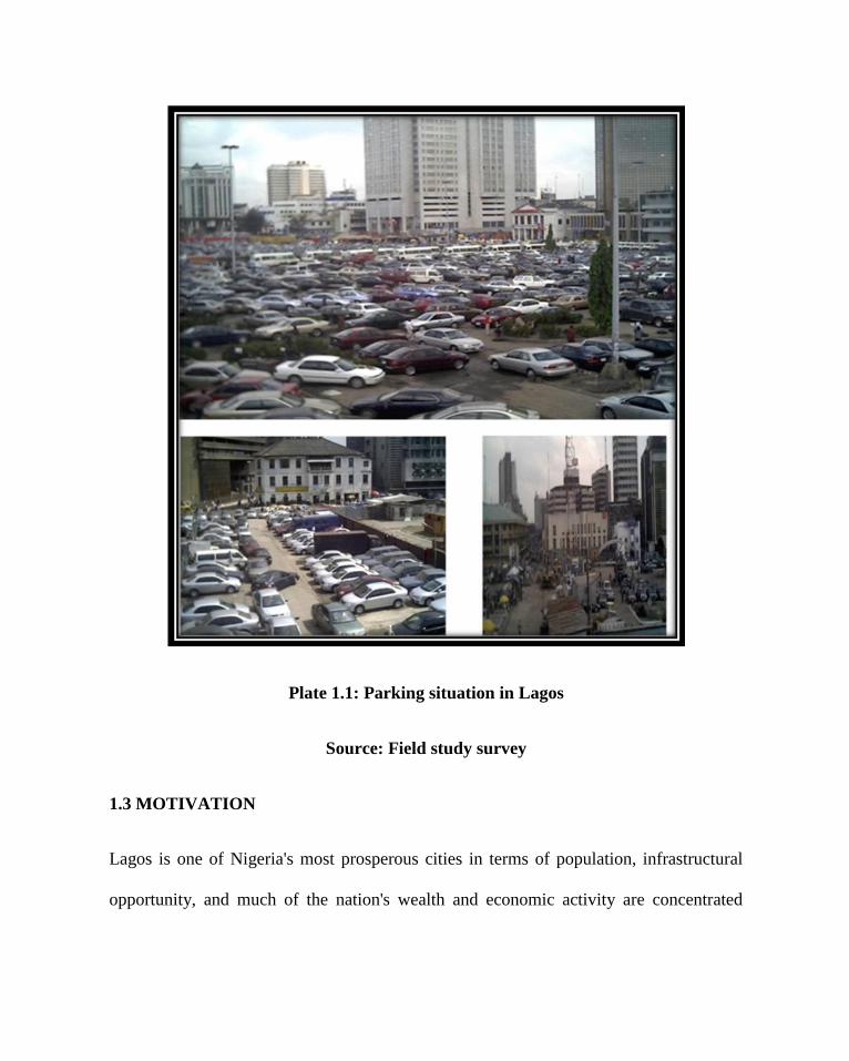
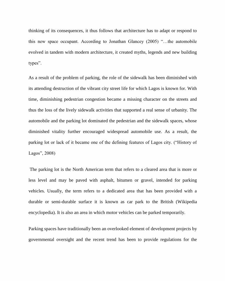
Plate 1.1: Parking situation in Lagos
Source: Field study survey
1.3 MOTIVATION
Lagos is one of Nigeria's most prosperous cities in terms of population, infrastructural
opportunity, and much of the nation's wealth and economic activity are concentrated
there. More than half of Nigeria's industrial capacity is located in Lagos mainland
suburbs, particularly in the Ikeja industrial estate. A wide range of manufactured goods
are produced in the city, including machinery, motor vehicles, electronic equipment,
chemicals, beer, processed food, and textiles. The commercial, financial and business
centre of Lagos and of Nigeria remains the business district of Lagos Island, where most
of the country's largest banks and financial institutions are located.
Because of its importance, the Lagos State Government proposes the conversion of all
open spaces and abandoned buildings on the Central Business District (CBD) of Lagos
Island into shopping malls and multi-storey car parks in order to attract investment into
the Island. (Honourable Oyinlomo Danmole, Special Adviser to the State Governor on
Central Business Districts in the State). The proposal is also meant to restore sanity and
aesthetic beauty of the Island which has, over the years, suffered a high level of
environmental abuse and infrastructural degradation and vandalism by street traders,
urchins and loafers. “It is regrettable that the island; the central business district (CBD)
has no proper car parks befitting her status”. (Honourable Oyinlomo Danmole, Special
Adviser to the State Governor on Central Business Districts in the State)
1.4 AIM AND OBJECTIVES
The aim of this research is to effectively manage space by the design of a multi-level car
parking decks to curb the automobile litter in the high density central cores with

particular reference to Marina-Lagos, in a quest to effectively manage what is left of the
spaces in urban centers.
A study of the traffic situation of the Marina-Lagos including the volume of cars going to
business areas, market and also offices which is quite high is made to provide an insight
into how an architectural solution can be arrived at, so that parking problems can be
greatly reduced.
Furthermore the objectives could be stated as follows:
To create awareness that the traditional urban fabric which was prevalent in the
Lagos central business district has been destroyed.
To design a multi-storey car complex which would cut down the amount of
open land space used as parking through vertical arrangement of parking stalls
in storey above each other.
To make the complex a public building through the proper integration of
ancillary activities this, will ensure the proper functioning of the multi-storey
car complex.
To properly integrate the building structure into the surrounding environs

through its proper articulation and aesthetics, beautifying the streetscape.
To create free space around the building structure this could be landscaped.
To provide a garage that will improve parking system in Marina-Lagos and
relieve the roads of automobile.
To direct the flow of arriving and departing motorist to eliminate conflict and
reduce usage of signboards etc.
To provide a garage that will ensure safety of automobile and their user.
To design an economical viable garage.
To provide a garage that will restore sanity and aesthetic beauty to Lagos state.
To provide a garage that will enhance the effective movement of automobile and
their users.
1.5 SCOPE OF THE PROJECT
The scope of this research shall be restricted to space planning and management in the
design of a multi-storey car complex. The design shall cover a detailed planning proposal
for construction by the Lagos State Government as a part of the ongoing Mega City
project embarked upon for upgrading Lagos State.
The project is based on analysis of the case studies, interviews, journals, questionnaires
etc. The scope of work is based on the population it is intended to serve. Marina (Lagos

island) is the central business district (CBD) serving the banks and offices, the
population of cars are between 1500 to 2000.
As a multi-storey complex, it will serve as a commercial building, public building as well
as a car park generating revenue. Thus the scope shall include: ancillary facilities such as
let-able shops, restaurant, lounge/ relaxation area, cybercafé, mini-garage, and car wash.
Other facilities such as ticketing booths, arrivals, departure, and information counters,
and offices spaces
1.6 RESEARCH METHODOLOGY
Information for this research work shall be obtained by a combination of methods
classified under the descriptive methodology and divided into both the primary and
secondary sources
1.6.1 Primary sources
The primary sources for data include those methods whereby information is gathered
direct from source for this work by the following methods:
A. Interviews: This method covers the collection of information from people directly
involved or affected by the research problem. This is to include a random sample of car
owners who work daily within the Marina district, car park security men who monitor
the cars parked within the car parks and the movement pattern of these cars, local

government officials for Lagos Island who may be able to give out information.
B. Case studies: This involves the on-site collection of data through field survey of how
previous designs have been able to achieve similar solution to this research problem and
the problems they have come across. It also includes the areas of problem study, getting
down to the affected area of the central business district to see how the problem really
affects.
C. Secondary sources
Secondary sources of information shall be from already collected data by other
researchers through books, journals, published and unpublished literatures, and also the
internet.
1.7 ARCHITECTURAL SIGNIFICANCE
The importance of such research work architecturally is the ability of buildings to adapt
to new challenges that increase in technology posses on it. Before now, buildings only
had the function of housing man and his other valuables. Increase in technology and the
advent of the automobile, ushering in the mass use of the automobile to the extent that it
begins to litter the environment, can be solved by adapting our building to house this
mess. This research work would create a framework for the design of buildings that
would house not only man, but the monster he has created for himself in a bid to ease his
activities on the planet, creating the awareness that architecture should adapt to various
changes in function over time, providing solution to environmental problems in the
society.
1.8 PROJECT LIMITATION
The major constraints encountered in the course of this research was refusal of
government and private officials to provide necessary assistance in areas of taking of
photographs and provision of information necessary for the research.
Also, the multi-storey car parks visited had heavy security which discouraged easy and
better study of the building all in the bid to prevent loitering and theft in the complex.
Due to lack of funds, foreign case studies will not be visited to be appreciated first hand.
1.9 SOURCES OF FINANCE FOR THE PROJECT
This project would be financed through a joint venture arrangement. The state
government, local government, other governmental organization and banks such as UBA
bank, Intercontinental bank, Union bank, Wema bank, Eco bank amongst others, would
be major financiers.

CHAPTER TWO
2.1 HISTORY OF AUTOMOBILE
The history of the automobile actually began about 4,000 years ago when the first wheel
was used for transportation in India. In the early 15th century the Portuguese arrived in
China and the interaction of the two cultures led to a variety of new technologies,
including the creation of a wheel that turned under its own power. By the 1600s small
steam-powered engine models had been developed, but it was another century before a
full-sized engine-powered vehicle was created.
In 1769 French Army officer Captain Nicolas-Joseph Cugnot built what has been called
the first automobile. Cugnot’s three-wheeled, steam-powered vehicle carried four
persons. Designed to move artillery pieces, it had a top speed of a little more than 3.2
km/h (2 mph) and had to stop every 20 minutes to build up a fresh head of steam.
As early as 1801 successful but very heavy steam automobiles were introduced in
England. Laws barred them from public roads and forced their owners to run them like
trains on private tracks. In 1802 a steam-powered coach designed by British engineer
Richard Trevithick journeyed more than 160 km (100 mi) from Cornwall to London.
Steam power caught the attention of other vehicle builders. In 1804 American inventor

Oliver Evans built a steam-powered vehicle in Chicago, Illinois. French engineer
Onésiphore Pecqueur built one in 1828. (Microsoft Encarta, 2007)
British inventor Walter Handcock built a series of steam carriages in the mid-1830s that
were used for the first omnibus service in London. By the mid-1800s England had an
extensive network of steam coach lines. Horse-drawn stagecoach companies and the new
railroad companies pressured the British Parliament to approve heavy tolls on steam-
powered road vehicles. The tolls quickly drove the steam coach operators out of business.
During the early 20th century steam cars were popular in the United States. Most famous
was the Stanley Steamer, built by American twin brothers Freelan and Francis Stanley. A
Stanley Steamer established a world land speed record in 1906 of 205.44 km/h (121.573
mph). Manufacturers produced about 125 models of steam-powered automobiles,
including the Stanley, until 1932.
Most automobiles at the turn of the 20th century appeared more or less like horseless
carriages. In 1906 gasoline-powered cars were produced that had a style all their own. In
these new models, a hood covered the front-mounted engine. Two kerosene or acetylene
lamps mounted to the front served as headlights. Cars had fenders that covered the
wheels and step-up platforms called running boards, which helped passengers get in and
out of the vehicle. The passenger compartment was behind the engine. Although drivers

of horse-drawn vehicles usually sat on the right, automotive steering wheels were on the
left in the United States. (Microsoft Encarta, 2007)
In 1903 Henry Ford incorporated the Ford Motor Company, which introduced its first
automobile, the Model A, in that same year. It closely resembled the 1903 Cadillac,
which was hardly surprising since Ford had designed cars the previous year for the
Cadillac Motor Car Company. Ford’s company rolled out new car models each year, and
each model was named with a letter of the alphabet. By 1907, when models R and S
appeared, Ford’s share of the domestic automobile market had soared to 35 percent.
By 1920 more than 8 million Americans owned cars. Major reasons for the surge in
automobile ownership were Ford’s Model T, the assembly-line method of building it, and
the affordability of cars for the ordinary wage earner. (Microsoft Encarta, 2007)

Plate 2.1: Automobiles through the years.
Source: Microsoft Encarta 2007
2.2 HISTORY OF CAR PARKS
The early cars, being objects of ostentation for the rich, dwelled in old carriage houses or
stables which were miniature replicas of the main house as the shelter for automobiles
was not a thing for design consideration. Over time, the carriage house evolved into a
form of its own as the then rich would have it: a wash and waxing shop for their
expensive toys, often with a lowly chauffeur-cum-mechanic living above or by its side
sometimes appearing with a gas pump out at the front (Holtz, 2001).

As middle-class suburban dwellers bought their own cars, their smaller houses
developed wooden or brick garages - detached from the house to avoid dangers that the
new loved machine might pose to the family. This more modest homeowner's garage
might still be built to match the architecture of the parent house. Soon, a more stylish
home for the new vehicle emerged when Frank Lloyd Wright, as enthralled with the
motorcar, brought not only architectural modernity but mobility to one of his Oak Park
homes in the form of a built-in garage and sketched a design for a service station (Holtz,
2001).
A clearer view of the history of public parking in the United States would have to be
broken down to before and after the World Wars I&II.
2.2.1 BEFORE WORLD WAR II
The period between the World War I and II found car parks to be a vital element of the
cityscape. Developed nations such as the United States recorded car parking to have
reduced downtown street area by one third to one half. Against this, the increase in
technology and mass production techniques further increased the number of cars in use
worldwide to an extent whereby parking at the curbs met only a small percentage of the
total parking requirements for the average city. At this point, efforts began to be made to
ban or limit curb parking and to increase off-street parking to relieve congestion and to
house vehicles during the busiest times of the day.

As early as 1917, the first noted commercial car park in the United States was established
by Max Goldberg in Detroit, Michigan, although some attribute this to Herman R.
Schmitt in Dusquense Pennsylvania in 1914 (Jackle, John and Sculle, 2004). During this
period, parking lots were usually vacant lands converted for such use by land owners so
as to finance property taxes, especially in the United States where companies such as the
Ford Motor Company ensured that the motor car was made available to the general
masses. With time and the increase in automobile use, land owners found the business of
parking cars on their properties to be a very profitable one with little or no liabilities
attached. Land owners found that parking lots required little or no site renovation,
maintenance or operating fees. It was also discovered that in some areas, renting a
parking stall on an hourly or daily basis proved to be more advantageous than leasing
square footage in a building on a monthly or yearly basis. The early car parks were so
profitable and easy to manage that owners began tearing down unsuccessful buildings to
pave more surfaces for parking. The parking lot was beginning to assume a key role in
the definition of the city’s landscape.
As the use of motorcars continued to increase in the urban centers, the government began
developing car parks between road lanes and by the sides of the roads in places such as
New York. This solution only solved the problem for the moment, but the increasing car
use soon simply overwhelmed the solution.
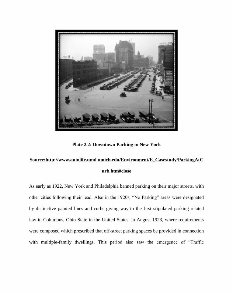
Plate 2.2: Downtown Parking in New York
Source:http://www.autolife.umd.umich.edu/Environment/E_Casestudy/ParkingAtC
urb.htm#close
As early as 1922, New York and Philadelphia banned parking on their major streets, with
other cities following their lead. Also in the 1920s, “No Parking” areas were designated
by distinctive painted lines and curbs giving way to the first stipulated parking related
law in Columbus, Ohio State in the United States, in August 1923, where requirements
were composed which prescribed that off-street parking spaces be provided in connection
with multiple-family dwellings. This period also saw the emergence of “Traffic

engineering” as a profession, and with it came off-street parking’s first appearance in
zoning.
Plate 4 below, probably from the 1930s, shows a new parking system in Detroit: the lane
of cars against the curb to the right is parked, but those cars in the lane next to it must
have the driver at the wheel.
Plate 2.3: Street-side parking in Detroit
Source:http://www.autolife.umd.umich.edu/Environment/E_Casestudy/ParkingAtC
urb.htm#close
More effective was the introduction of the parking meter in Oklahoma City in 1935, with
almost 3,000 towns and cities (world-wide) utilizing them by 1950s. In recent years,
central city parking in the United States has been generally more available than in
European and Asian cities, but the problem has not disappeared. It is compounded by the
fact that not only motorists, but merchants, property owners, commercial fleets, taxis, and
mass transportation all have needs and responsibilities for adequate parking.
By 1925 in the United States, 20% of commuters drove to work in a private automobile.
This increasing statistics of the motorcar led inventors into relentless works on
mechanical solutions to ease the congestion of car parks. The United States Conference
of Cities declared parking, “the most widely discussed and relevant issue in cities today”,
and the House of Tomorrow featured a two-car garage.
(http://www.autolife.umd.umich.edu/Environment/E_Casestudy/ParkingAtCurb.htm#clos
e)
2.2.1.1 The Mechanical Garage
The first mechanical garage in the United States was built in Cincinnati in 1932. It was
designed to accommodate nearly 400 cars and used a converted elevator system to hoist
individual vehicles from a central receiving area to any one of its 24 floors. As soon as
the vehicle reaches the appropriate floor, dollies and/or a live attendant pushed the
vehicle into its parking space. This garage was in constant use until it was shut down and
demolished to make room for new buildings in 1979.
(http://www.roboticparking.com/productline.html).

The advantages of the mechanical garage included the fact that it offered a pollution free
alternative. No cars are running inside, so there are no choking car emissions to have to
deal with inside the garage. Also, because cars do not have to circle around and around
the block looking for spaces, there are less pollution and less traffic from cars driving at
slow paces for extended periods of time. Cars get off the street faster.
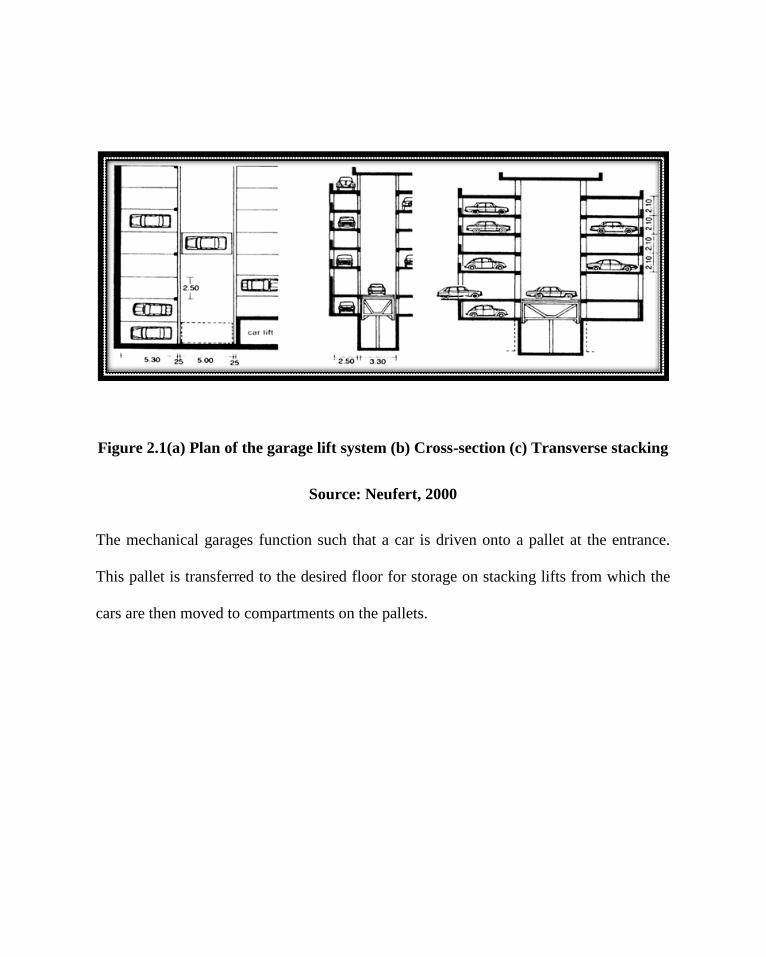
Figure 2.1(a) Plan of the garage lift system (b) Cross-section (c) Transverse stacking
Source: Neufert, 2000
The mechanical garages function such that a car is driven onto a pallet at the entrance.
This pallet is transferred to the desired floor for storage on stacking lifts from which the
cars are then moved to compartments on the pallets.
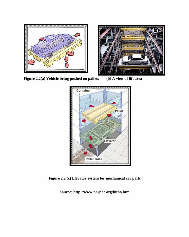
Figure 2.2(a) Vehicle being pushed on pallets (b) A view of lift area
Figure 2.2 (c) Elevator system for mechanical car park
Source: http://www.narpac.org/intho.htm

The mechanical garage idea was not so vast in United States for a long while basically
due to the fact that there was plenty of land and parking spaces, whereas in Europe, Asia
and Japan, where land is so scarce, hundreds of mechanical garages were built between
the mid 1950's and the late 1980's. Most are still in operation. The largest of these
garages, accommodating 849 cars, is an underground garage built by the former Krupp
Manufacturing.
By the mid-1930 the mechanical garage, which seemed so full of promise a decade
earlier, was being replaced by the multi-story “cage garage”. This change was due to the
imperfections of these early technologies, which eventually proved unsatisfactory, as
installation costs were high, mechanical and electrical malfunctions were common, and,
perhaps most damning, these mechanical garages did not satisfy the demand for speedy
service during peak traffic flows (Jackle, John and Sculle, 2004). The principal advantage
of the cage garage was its open deck design. The “Cage Garage” was the first open-deck
parking garage, developed in 1933 by Sam Elliot in Boston, Massachusetts (Jackle, John
and Sculle, 2004). There was no envelope, and subsequently, no ventilation or fire
protection systems. This in turn considerably lowered construction and maintenance
costs, making the cage garage an attractive option for parking developers. The 1930’s
saw two other critical events in parking: the appearance and widespread use of the
parking meter, and a legal construct of parking.

Shortly before the World War II there were vast changes in the way car parks were
viewed in the United States which brought tremendous change to the parking industry.
2.2.2 AFTER WORLD WAR II
With the increased need for speedy economic growth and stability after the world war,
clearly a lot of things changed. The open spaces which were previously used for parking
was no longer adequate to house the large numbers of the automobiles being used by the
city dwellers. A 1981 transit study hypothesized that if an automobile is in use for every
two people, then each automobile in a city might need two off-street parking spaces of
250 square feet per space. This would mean that for every 10,000 people, fifty acres
would be required for parking alone, which adds 15 to 25 percent to urban land
requirements or street space.
By 1946 over 90% of Americans were traveling by car. Downtown parking was in such
demand that it was estimated 30% of traffic during shopping hours was devoted to the
quest for a parking space. The gradual revelation of these facts made the government in
its planning to begin passing into legislation the expansion of the roles of the car and the
parking lot rather than restraining them. In response to the increasing demand, more land
and municipal funds were devoted to parking. By 1948, parking had become the most
important single problem facing the Central Business Districts of large cities and was the
subject of numerous publications.
By 1951 a National Parking Association had been formed in the United States, nearly 200
cities had adopted minimum off-street parking requirements in their zoning, an increase
of over 275% over six years, and a variety of multistory parking types had begun to
develop. The distinguishing feature of the multistory park was its ramp system or vertical
circulation. At this time there were already three primary ramp systems in use: spiral,
continuous and opposed, and modified split level.
2.2.2.1 THE MULTI-STOREY CAR PARK
“A multi-storey car park is a building (or part thereof) which is designed specifically to
be for automobile parking and where there are a number of floors or levels on which
parking takes place. It is essentially a stacked car park.”
(http://en.wikipedia.org/wiki/Parking_garage).
The vertical movement of cars between floors is possible by either of the following
means
Interior ramps - the most common type
Exterior ramps - which may take the form of a circular ramp
Vehicle lifts - the least common
The multi-storey car park is a feature that had already come into existence even before
World War II, but was not so commonly used. The mechanical garage seemed to be the

preferred technology at that period. Due to several failures and maintenance challenges,
the multi-storey car park was chosen as an alternative
The earliest known multi-storey car park was built in 1918. It was built for the Hotel La
Salle in Chicago, IL at 215 West Washington Street in the West Loop area of downtown.
It was designed by Holabird and Roche. The Hotel La Salle was demolished in 1976, but
the parking structure remained because it had been designated as preliminary landmark
status. The Hotel LaSalle multi-storey was demolished in 2005 after failing to receive
landmark status from the city of Chicago. Jupiter Realty Corp. of Chicago is constructing
a 49-storey apartment tower in its place, with construction to begin in September 2007.
Relative economic and domestic stability thrived in the United States during the 1950s
probably due to the stable political and international relations platform that the country
operated from at that period. This made the single family detached home with a two car
garage away from the troubles of the city become a reality for millions – the America
dream, due in part to new suburban infrastructure created through the Federal Highway
Acts of the 1940s and 1950s. One of the most popular of this acts passed in 1956 was
often referred to as “the greatest public works project in history”. This act differed from
its predecessors in terms of the scale. The then President, Dwight Eisenhower, envisioned
broad ribbons of roadway crossing the country and his idea was in complete accord with
many Americans who were coming to value individual mobility as a cornerstone of the

American way of life. This act included the provisions of parking spaces at every
destination off the interstate.
This act was seen to have had tremendous effects in solving the problems of parking in
the United States. It calls for all new buildings to make ample provision for parking space
required for its own uses. At this time automobiles had grown since their introduction at
the turn of the century, necessitating larger stalls, and more maneuvering room. Wide
aisles, ample berths, and convenient footways resulted in greater ease, efficiency and
safety in entering and leaving (Mayer, 2005).
A good comparison can be set between the year 1925 and 1954, the percentage of early
morning commuters in an automobile was 20% in 1925 and doubled to 40% by 1954. In
1946, 12 states had specific provisions in their zoning for off-street parking; by 1953 the
number had grown to 33.
A remarkable development in multi-storey car park was in The Republic of Ireland,
though with a population of just over 4 million, it had almost 1.3 million private cars up
from 800,000 in 1990. The development of multi-storey car parks did not seriously begin
until about 1980, and now currently possesses above 70 purpose-built public multi-storey
car parks which date back to the last 15 years (Keilthy, 2001).
2.2.3 PROLIFERATION OF AUTOMOBILE USE IN NIGERIA
2.2.3.1 Pre-colonial Nigeria
Societies in pre-independence Africa countries have been predominantly rural for the
most part of their history. By the mid-20th
century, most Africa countries began to gain
independence from their colonial masters which led to apparent changes in their social
and economic lives. The emerging independent countries experienced a rapid and
profound reorientation of their social and economic lives that caused attraction towards
cities leading to urbanism. Urbanization was first noticeable in the state capitals and later
in various expanding cities and trade routes.
2.2.3.2 Post Colonial Nigeria
Nigeria has experienced a phenomenal growth in population and urbanization, but its
experience has also been unique in scale, in pervasiveness, and in historical antecedents.
Nigeria became an independent country on October 1, 1960 with her capital in Lagos. It
became a republic on October 1, 1963, thus breaking all the ties with British colonialist.
The “oil boom” of the 1970 and 1980 brought about an unprecedented prosperity and
development of the nation with primary focus being on Lagos State, the then Federal
Capital. There were massive improvements on infrastructural development. New roads
were constructed with bridges linking the Lagos Mainland with the Island to ease

accessibility of people. There were also growing manufacturing industries, large
construction companies, and governmental institutions, along with a great variety of
small business enterprises, many in the informal sector.
These negative effects of transport manifest in different degrees in the urban centers of
Nigeria. Because most Nigerian cities pre-date the automobile, houses and activity space
have to be destroyed to give room for parking lots and right of way for the automobile.
The expansion of roads and the building of flyovers in various parts of metropolitan
Lagos led to the destruction of residential houses and the displacement of many families.
Also in the new Federal Capital territory, a large number of houses were destroyed
recently in Nyanya to give room to the dual carriage way being constructed between
Nyanya and Abuja city. Although in these cases, such displaced persons are relocated
and/or compensated, there is usually a permanent break in friendship that has been
cultivated over a long period of time. Traffic congestion is another major transportation
problem of Nigerian cities. The chaotic situation is observable in virtually all the streets
of metropolitan Lagos. The streets of Ibadan, Abuja, Kano, Kaduna, Onitsha, Aba, and
Port Harcourt depict various levels of traffic congestion. Even the medium urban centres
like Ilorin are beginning to witness congestion problems. The cost of congestion in urban
centres of Nigeria if computed will be enormous. In a study on the contribution of freight
vehicles to congestion problems along Wharf Road in Apapa, Lagos, Ogunsanya (1983a)
estimated that the cost of congestion on that route alone amounted to N22.4 million in
1984 or N3.3 billion at 2002.

Nigeria’s urbanization rate is put at a conservative estimate of 5% (Sada, 1973).
Automobiles have had the most far reaching effects on the physical growth of cities.
They essentially remove the past limitations on urban expansions. Nigerian cities like
other cities in the world are becoming more and more dependent on the use of the
automobile and this, in turn, is responsible for a high proportion of the fuel consumption
in the country. Although the level of private car ownership is still very low, for example
the number of automobiles per 1000 population of Lagos is only 22.8 in 1970 as
compared to 316 and 248 per 1000 population in Washington and Paris respectively
(World Bank, 1975). The rate of growth of automobile use in Nigeria has been
phenomenal. Whereas the rate of growth of population of Lagos between 1960-1970 was
about 7.9% the rate of growth of automobiles was 15.5% in the same period (World
Bank, 1975).
Lagos is an urban complex that embodies tremendous contrasts. As the former national
capital and the major port of one of the largest country in Africa, it is a powerful magnet
for migrants from all over Nigeria. The rapid urban growth which Nigeria has
experienced is well manifested in Lagos, the major parts of which are the product of
modern economic, social and political forces in interaction with traditional culture which
was the factor that distinguished life in the city from that in the countryside.
Consequent upon that, the vast majority of salaried jobs, the increased opportunity to
connect with the rich and powerful, opportunity for great varieties of informal sector

business enterprises, and the excitement of night life that was non-existent in most rural
areas, were some of the factors that made the city lively and attractive. The pull into
Lagos State became increasingly phenomenal that the State has become legendary for its
congestion and other urban problems.
In a bid to keep congestion under control the government in urban centers such as Lagos
began implementing some laws such as the Lagos Traffic Edict that placed bans on
certain types of cars or certain categories of cars plying certain routes in the congested
zone, regulation of parking spaces and amounts charged for it.
CHAPTER THREE
3.0 CASE STUDIES
3.1 MURTALA MOHAMMED DOMESTIC AIRPORT’S MULTI-STOREY
CAR PARK. IKEJA, LAGOS.
3.1.1 Source of Information
Visit to the multi-storey car park, interviews conducted, sketches and photograph taken.
3.1.2 Client
The management is between the Federal Government of Nigeria and Bi-Courtney
Consortium in a Build-Operate-and-Transfer contract with for a period of 35years.

3.1.3 Architect
The multi-storey car park was designed and built by construction giant Stabilini Visioni
in Nigeria and commissioned on the 7th
of April, 2007 by the then president Olusegun
Obasanjo.
Plate 3.1(a) Exterior view of the Murtala Mohammed Airport Multi Storey Car
park
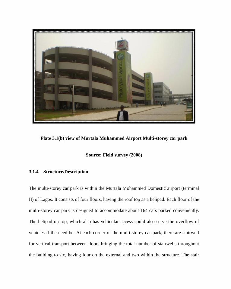
Plate 3.1(b) view of Murtala Muhammed Airport Multi-storey car park
Source: Field survey (2008)
3.1.4 Structure/Description
The multi-storey car park is within the Murtala Mohammed Domestic airport (terminal
II) of Lagos. It consists of four floors, having the roof top as a helipad. Each floor of the
multi-storey car park is designed to accommodate about 164 cars parked conveniently.
The helipad on top, which also has vehicular access could also serve the overflow of
vehicles if the need be. At each corner of the multi-storey car park, there are stairwell
for vertical transport between floors bringing the total number of stairwells throughout
the building to six, having four on the external and two within the structure. The stair

cases have artificial lighting with the use of backup power fluorescent lamps for
security especially at night.
Plate 3.2: Views of Stairwell around the Murtala Muhammed Airport Multi-storey
car park
Source: Field survey (2008)
At every level and on every floor, there are sprinklers which line up the entire soffit.
Each floor has six rows of fire-sprinkler water-piping running its entire length at equal
spacing. The sprinkler discharge outlets are fitted to the pipes at regular intervals of
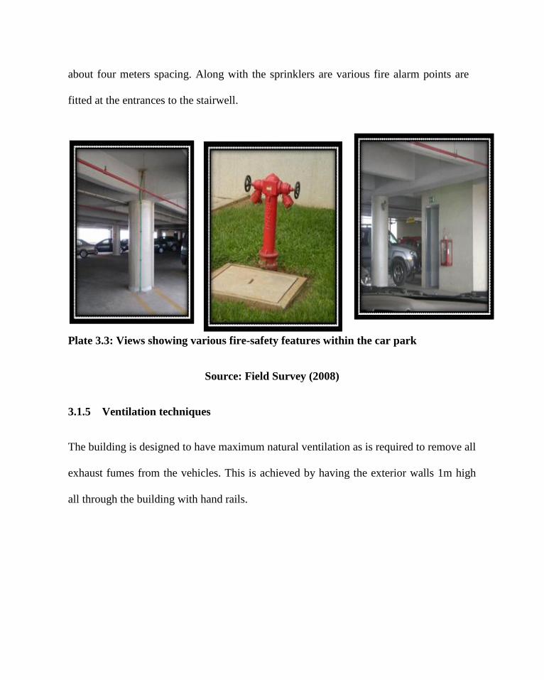
about four meters spacing. Along with the sprinklers are various fire alarm points are
fitted at the entrances to the stairwell.
Plate 3.3: Views showing various fire-safety features within the car park
Source: Field Survey (2008)
3.1.5 Ventilation techniques
The building is designed to have maximum natural ventilation as is required to remove all
exhaust fumes from the vehicles. This is achieved by having the exterior walls 1m high
all through the building with hand rails.
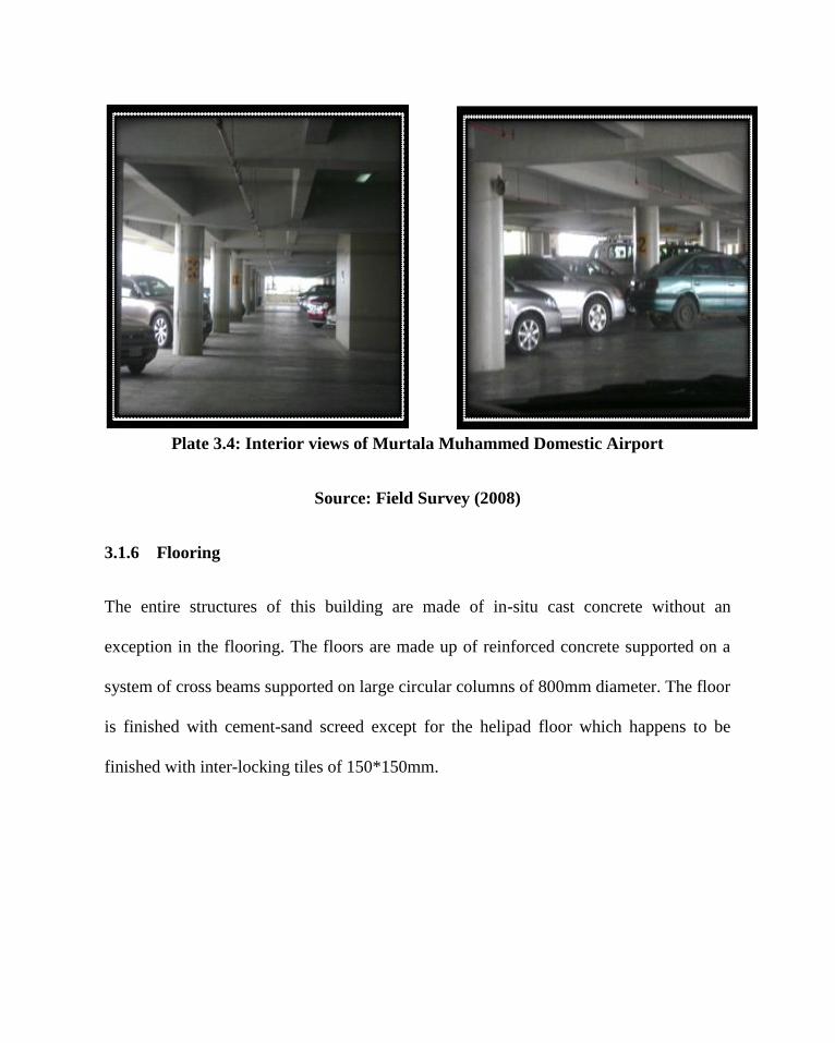
Plate 3.4: Interior views of Murtala Muhammed Domestic Airport
Source: Field Survey (2008)
3.1.6 Flooring
The entire structures of this building are made of in-situ cast concrete without an
exception in the flooring. The floors are made up of reinforced concrete supported on a
system of cross beams supported on large circular columns of 800mm diameter. The floor
is finished with cement-sand screed except for the helipad floor which happens to be
finished with inter-locking tiles of 150*150mm.
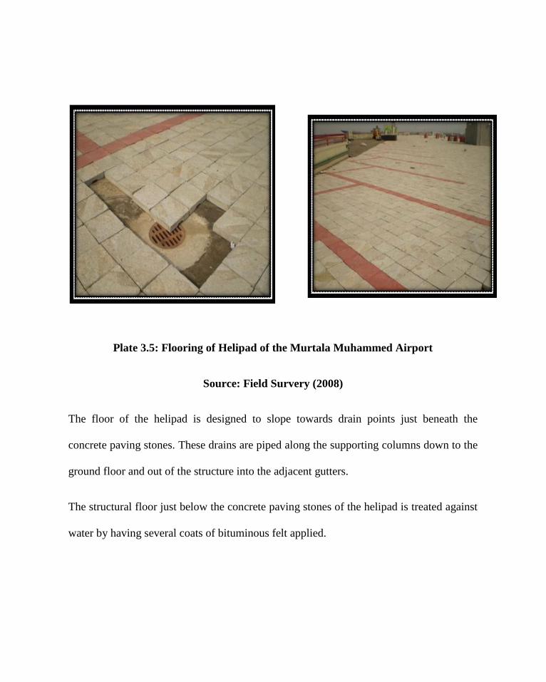
Plate 3.5: Flooring of Helipad of the Murtala Muhammed Airport
Source: Field Survery (2008)
The floor of the helipad is designed to slope towards drain points just beneath the
concrete paving stones. These drains are piped along the supporting columns down to the
ground floor and out of the structure into the adjacent gutters.
The structural floor just below the concrete paving stones of the helipad is treated against
water by having several coats of bituminous felt applied.
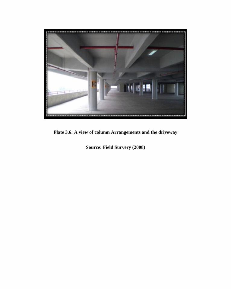
Plate 3.6: A view of column Arrangements and the driveway
Source: Field Survery (2008)

MURTALA MUHAMMED
AIRPORT TERMINAL
ON
E W
AY
ON
E W
AY

Figure 3.1: Site plan sketch plan
Source: Field survey (2008)


Figure 3.2: Typical floor plan sketch plan
Source: Field survey (2008)
3.1.5 MERITS
The ramp at the east and west side of the car park are for entry and exit which
separates traffic and reduces congestion during rush hours.
Sign and direction boards are at every point to ensure that drivers can get
direction easily.
The multi-storey car park is linked to the airport terminal for easy pedestrian
access to and from the airport.
The stair cases are at strategic positions to aid vertical movement.
Payment for parking is efficient. Drivers pay depending on the amount of hours
their automobile will be parked.
Sprinklers are at the soffit of each floor in event of fire outbreak.
The walls are dwarf for free flow of air and lighting
3.1.6 DEMERITS
Lack of ancillary facilities for effective functioning of the car park.
Lack of provision for the disabled.
Separation of the parking stalls for long and short stay users was not considered.

CASE STUDY II
3.2 MEGA PLAZA MULTI STOREY CAR PARK VICTORIA ISLAND,
LAGOS.
3.2.1 Source of Information
Visit to the multi-storey car park, interviews conducted and photograph taken.
3.2.2 Client
Mega Plaza shopping mall
3.2.3 Architect
The multi-storey car park was designed by DHT Architects and completed in 2007.
3.2.4 Structure/Description
The Mega Plaza multi-storey car park is located directly opposite the Mega Plaza
shopping mall on Victoria Island, Lagos. The purpose of the design was to provide
adequate and safe parking spaces for the shoppers while in the mall, a feature which is a
scarce feature with shopping centers in the Lagos environs.

Plate 3.7: Front view of the Mega-Plaza Multi Storey Car park.
Source: Field Survey (2008)
The multi-storey car utilizes a split level ramp system in its design consisting basically of
four floors, with the fifth also designated for parking. The entire structure is basically
concrete and steel, having its structural frame in steel sections and the floors of precast
concrete.
3.2.5 Construction
The main frame work of the multi-storey car park is built in steel sections. Other features
such as the floors, stairwell etc is in concrete, though the steel is the dominant
construction material. The stairwells are located at the corners of the structure. The stair

system is the continuous dogleg revolving around a central load bearing core wall. The
stairwells are open to the air, having hollow tubular steel baluster.
Plate 3.8: Column support for Multi Storey Structure
Source: Field Survey (2008)
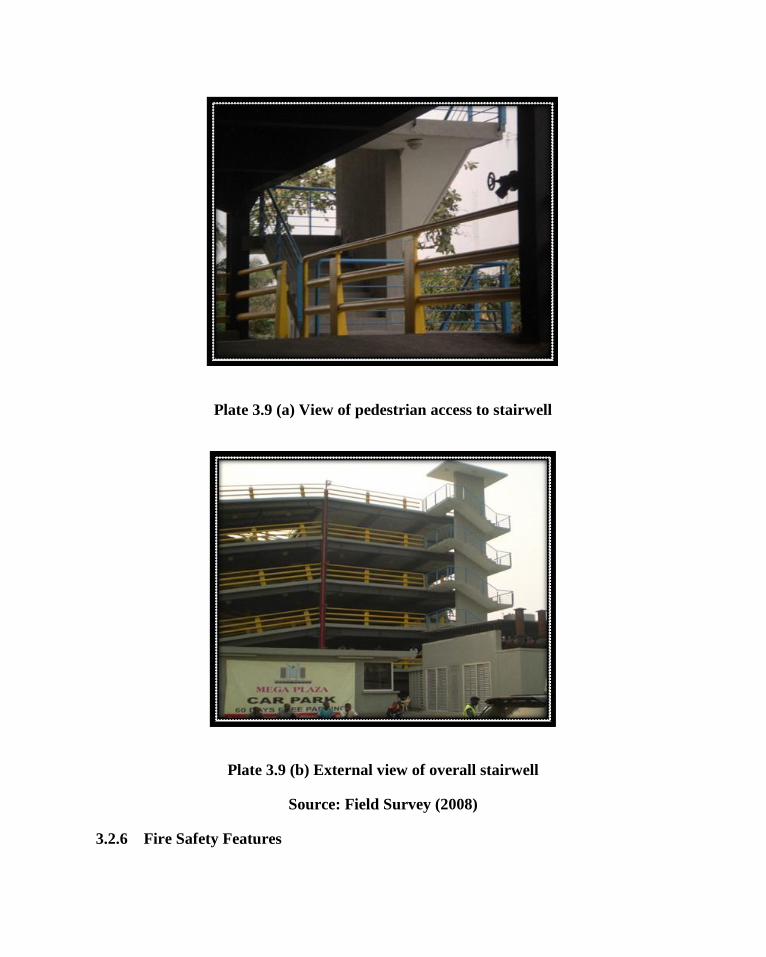
Plate 3.9 (a) View of pedestrian access to stairwell
Plate 3.9 (b) External view of overall stairwell
Source: Field Survey (2008)
3.2.6 Fire Safety Features

The entire structure is designed to have fire safety features. Along the steel stanchions are
fire hydrants attached for high pressure water supply in the case of a fire outbreak. The
stairwells are also well distributed for this reason.
Plate 3.10: View showing the inculcation of fire hydrant pipes along stanchions
Source: Field Survey (2008)
3.2.7 Lighting
The multi-storey car park is open on all sides so that lighting is not a problem except at
areas towards the middle of the building mass. These are taken care of with the use of
mechanical lighting which are regularly distributed all through the building hanging to
the soffit of the floor.

Plate 3.11 (a) Ground floor of parking showing the lighting system
Plate 3.11 (b) Another view showing the lighting system and arrangement
Source: Field Survey (2008)
3.2.8 Merits
The multi-storey car park is well lit and open on all sides.
Sprinklers are at the soffit of each floor in event of fire outbreak.
The stair cases are at strategic positions to aid vertical movement and for
emergency exit.
3.2.9 Demerits
During peak hours, the split ramp system used causes traffic congestion.
Lack of sufficient direction/sign board for better movement of drivers.

FOREIGN CASE STUDY
Case study III
3.3 TRINITY CENTER MULTI-STOREY CAR PARK; GATESHEAD,
NORTH-EAST ENGLAND
3.3.1 Client
E. Alec Colman Investments Ltd (a developer)
3.3.2Architect
The multi-storey car park was designed by Owen Luder in 1962 and opened for
operations in 1969

Plate 3.12(a): Elevational view of the Trinity centre Multi-storey car park
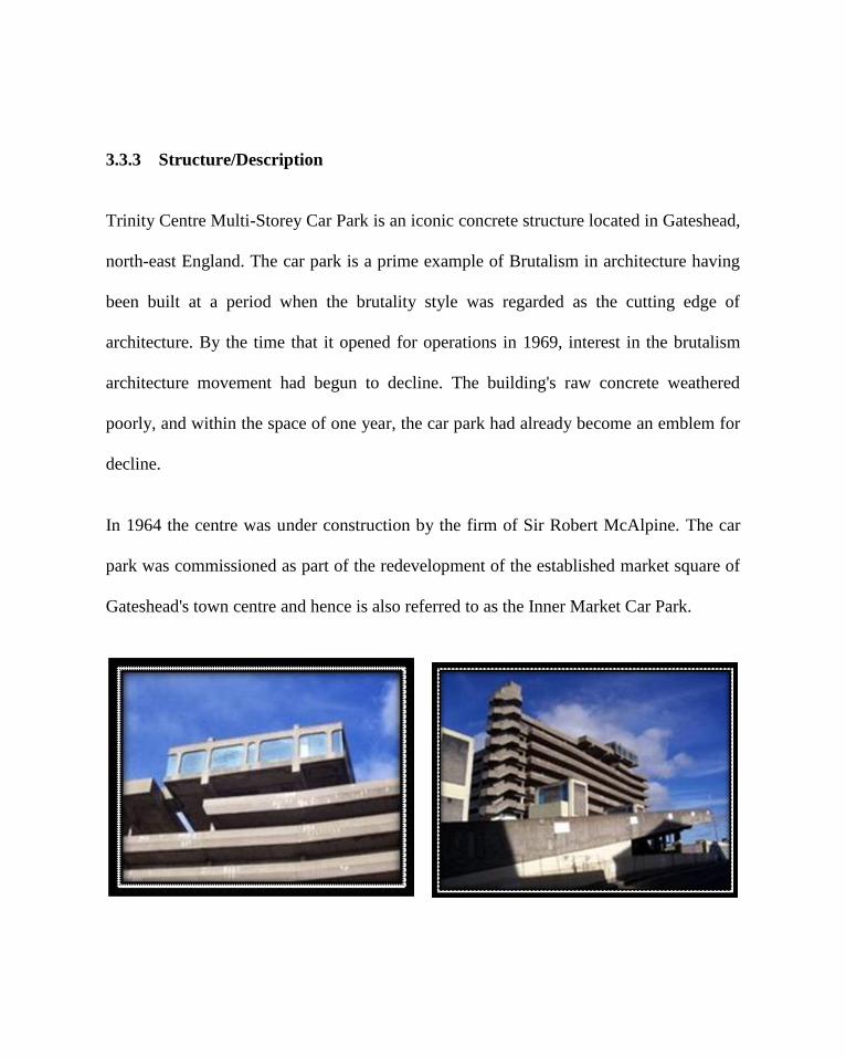
3.3.3 Structure/Description
Trinity Centre Multi-Storey Car Park is an iconic concrete structure located in Gateshead,
north-east England. The car park is a prime example of Brutalism in architecture having
been built at a period when the brutality style was regarded as the cutting edge of
architecture. By the time that it opened for operations in 1969, interest in the brutalism
architecture movement had begun to decline. The building's raw concrete weathered
poorly, and within the space of one year, the car park had already become an emblem for
decline.
In 1964 the centre was under construction by the firm of Sir Robert McAlpine. The car
park was commissioned as part of the redevelopment of the established market square of
Gateshead's town centre and hence is also referred to as the Inner Market Car Park.
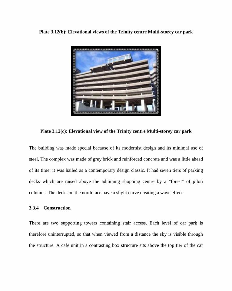
Plate 3.12(b): Elevational views of the Trinity centre Multi-storey car park
Plate 3.12(c): Elevational view of the Trinity centre Multi-storey car park
The building was made special because of its modernist design and its minimal use of
steel. The complex was made of grey brick and reinforced concrete and was a little ahead
of its time; it was hailed as a contemporary design classic. It had seven tiers of parking
decks which are raised above the adjoining shopping centre by a "forest" of piloti
columns. The decks on the north face have a slight curve creating a wave effect.
3.3.4 Construction
There are two supporting towers containing stair access. Each level of car park is
therefore uninterrupted, so that when viewed from a distance the sky is visible through
the structure. A cafe unit in a contrasting box structure sits above the top tier of the car

park connected to the access towers by an expressed glazed 'bridge' and an open
walkway. The cafe has large windows providing views across the Tyne Valley.
Plate 3.13: Interior view of parking bays and stall
Source: www.wikipedia.org

3.3.5 Disabled parking
There are 6 designated disabled bays in this car park. These are located on Level 2 (2no.),
Level 3 (2no.) and Level 4 (2no.). Vehicles displaying a valid disabled blue badge may
park free of charge in these disabled bays.
3.3.6 Stairs and Lifts
Stairs are located at the end side of the entire parking structure running from the 7th
floor
right to the ground. A fully accessible lift is available which operates between floors 1 to
7.
3.3.7 Other facilities
Motorcycles may park free of charge in this car park; There is one lift in operation; There
is CCTV in operation and also on foot security.
3.3.8 Merits
The multi-storey car park has provision for parking of motorcycles.
The security system is efficient
Vertical movement through stair and lift accesses all the floors
3.3.9 Demerits

The landscaping ultimately created an exposed and unattractive shopping precinct
on two levels with poor access.
The roof top cafe failed to find a tenant due to its poor location for business, and
was deemed unsafe and never opened.
Insufficient parking for the disabled.
3.3.10 Conclusion
In recent years the building has been regarded by some as quite an eyesore. This is
mainly due to its poor construction. There have been long standing problems of spalling
of the concrete in places, mainly on the concrete facing of the car park decks and service
towers. This is where the concrete has broken away from the steel reinforcing underneath
it. From time to time, contractors have had to examine the building and carry out patch
repairs to these areas.
At the top of the car park is a 5.500 sqft room which was originally designed as a
restaurant. The space was marketed but never occupied, and was closed to the public
from the buildings completion.
Case study IV
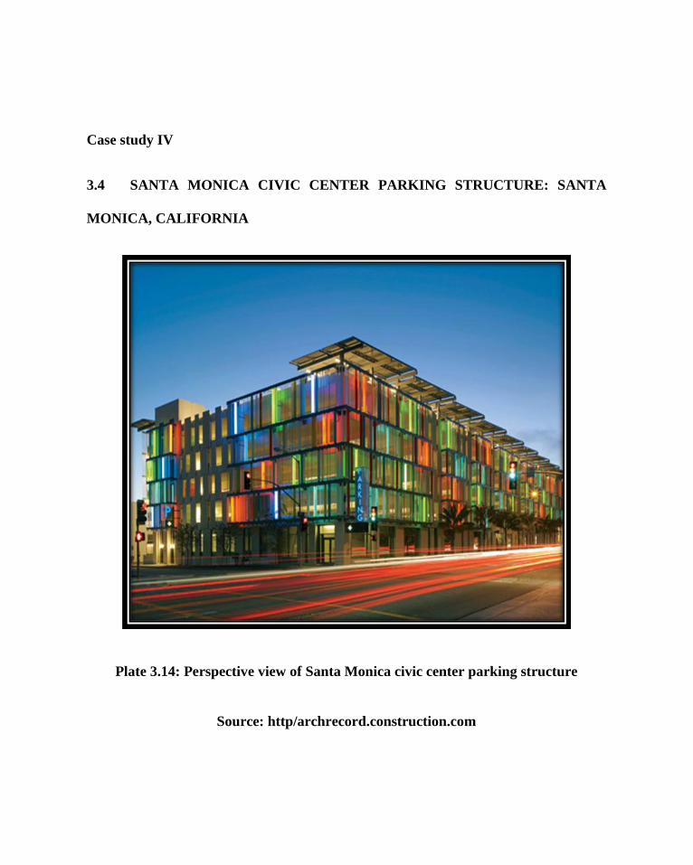
3.4 SANTA MONICA CIVIC CENTER PARKING STRUCTURE: SANTA
MONICA, CALIFORNIA
Plate 3.14: Perspective view of Santa Monica civic center parking structure
Source: http/archrecord.construction.com

3.4.1 Client
Santa Monica's civic center; California.
3.4.2 Architect
Santa Monica's civic center parking structure was designed by Moore Ruble Yudell
Architects & Planners. They developed a lively parking garage that simultaneously
cloaks and celebrates Southern California's car culture.
3.4.3 BACKGROUND
For better or worse, Los Angeles invented car culture. For the late academic Reyner
Banham and his continuing, devoted band of theory-mongers, ostensibly every building,
public space, and fragment of architecture in Los Angeles is really about the car. Moore
Ruble Yudell Architects & Planners' new parking structure for Santa Monica's civic
center is but the latest shout-out to Banham's influential thesis, set forth in 1971 in the
book Los Angeles: The Architecture of Four Ecologies. There is always a new example
to reaffirm Banham; his book is now unanimously understood as the first honest (and
perhaps most gushing) critique of Southern California's freeway culture-because the
trashy, flashy, global architecture culture that has emerged in Los Angeles from the late
1960s onward took the critic seriously.

Plate 3.13: Perspective view of Santa Monica civic center parking structure
Source: http/archrecord.construction.com

Parking garages, generally excluded from the categories of architecture and urbanism,
have typically been bland utilitarian boxes or podiums for superstructures. In a nod to
Venturi, Scott Brown’s super-graphics and decoration sheds, the parking garage for
Frank Gehry’s 1979 Santa Monica Place mall, north of the civic center, presented a scrim
of chain link printed with dim white letters spelling out the mall’s name. Gehry’s chain
link may have been tolerated more than loved, but the parking garage is a landmark, if
not a touchstone for architects pondering such building types.
3.4.4 DESIGN CHALLENGE
Santa Monica wanted this 900-car garage in order to redevelop adjacent land currently
used as surface parking. A new master plan for the civic center placed the garage at the
existing east entrance to the center, so the city, which is well-known in the area for its
aesthetic fussiness, didn’t want to build a concrete box in such a prominent location. The
architects were, in effect, hired to decorate the nearly 300,000-square-foot structure—to
wrap it in visual interest—as well as to tease more use out of what could have been a
dead box by planning 10,000 square feet of street-level retail to enliven the neighborhood
and introducing sustainable design strategies.


Plate 3.15: Perspective of Santa Monica civic center parking structure showing the
side view.
Source: http/archrecord.construction.com

3.4.5 CONSTRUCTION METHOD
Except for the addition of 25 percent fly ash to the cement mix, the 8-storey concrete
structure (two stories are below grade) is entirely conventional. Befitting a firm founded
by the late Charles Moore, the architects designed a porous skin of multicolored,
laminated, U-shaped glass channels that hang off the primary concrete structure and keep
the garage open to fresh air and views. Coupled with ribbed, precast-concrete panels and
stainless-steel mesh on the corner stair towers, the exterior cladding addresses the varied
urban contexts of the four elevations. For example, the west elevation’s glass strikes
green and blue colors for the ocean, while reds, greens, and blues respond to the eastern
freeway side. The designers also solved a long-standing problem in Southern California
by adding a dramatic, cantilevered, 19,200-square-foot, 181-kilowatt installation of solar
photovoltaic on the roof, which also provides shading for the top floor of parking.

Figure 3.3: Site plan of Santa Monica civic center parking structure.
Source: http/archrecord.construction.com

Figure 3.4: Floor plan and south elevation of Santa Monica civic center parking
structure the side
Source: http/archrecord.construction.com
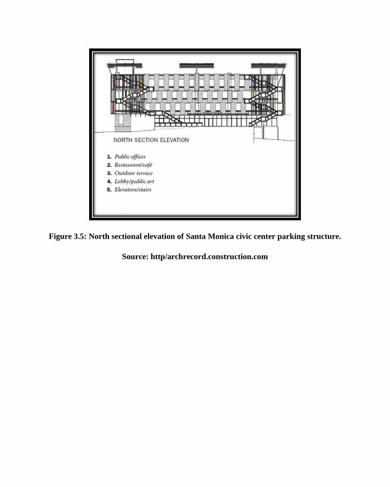
Figure 3.5: North sectional elevation of Santa Monica civic center parking structure.
Source: http/archrecord.construction.com

Figure 3.6: East sectional elevation of Santa Monica civic center parking structure
Source: http/archrecord.construction.com
3.4.6 Merits
The solar photovoltaic system on the roof provides shading for the cars parked on
the topmost floor as shown in figure 3.6.
The designer married the architectural character of the building with the
environment.
3.4.7 Demerits
Ramp circulation is limited and increases traffic congestion.

3.4.8 DEDUCTION FROM CASE STUDY
The above study and analysis of some existing multi-storey car park in Nigeria, U.S.A
and England reveal that they possess facilities that satisfy the multi-storey requirements.
The design of their physical structure also meets the same standard.
An assessment of the existing facilities will serve as a guide to the attainment of the
following standards:
Using a ramp system that is most effective to choose from.
Free flow of traffic: the pedestrian movement will be separate from the vehicular
movement.
Aesthetics of the structure should not be neglected.
Provision of adequate parking for the disabled.
Achievement of natural lighting.
Achievement of adequate natural ventilation.
Zoning of the ancillary facilities without interrupting vehicular movement.
Central positioning of elevators and stair cases in relation to the parking bay, in
such a way that they can be assessed directly from the lounge or lobby.
Creating a natural environment by using element peculiar to the environment.
Maximum attention to fire protection.
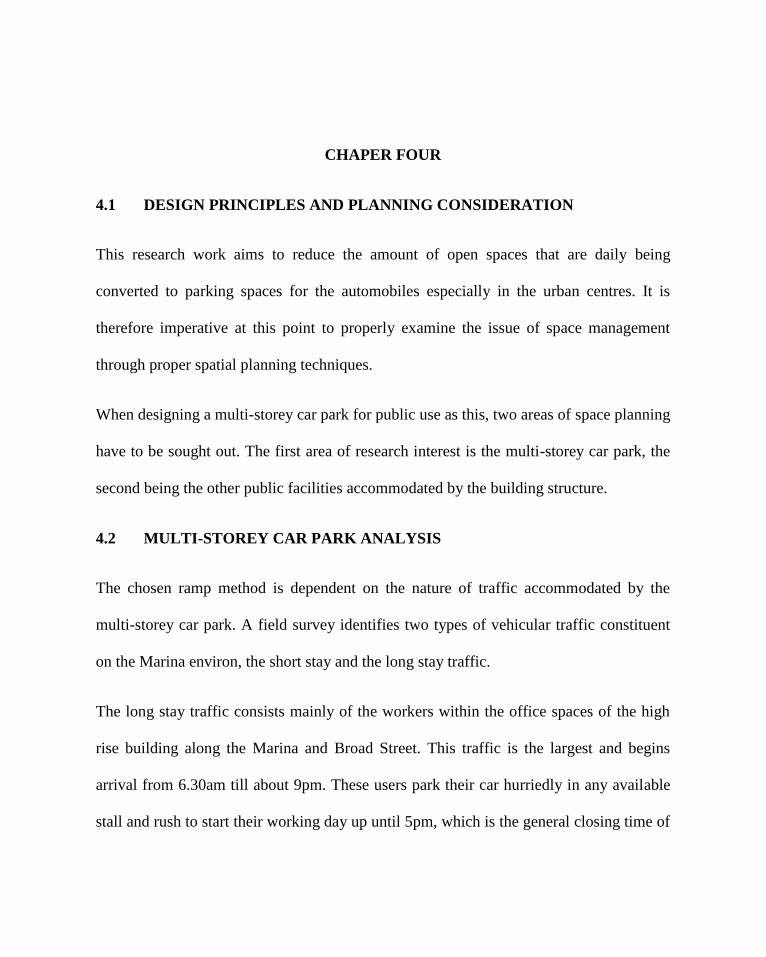
CHAPER FOUR
4.1 DESIGN PRINCIPLES AND PLANNING CONSIDERATION
This research work aims to reduce the amount of open spaces that are daily being
converted to parking spaces for the automobiles especially in the urban centres. It is
therefore imperative at this point to properly examine the issue of space management
through proper spatial planning techniques.
When designing a multi-storey car park for public use as this, two areas of space planning
have to be sought out. The first area of research interest is the multi-storey car park, the
second being the other public facilities accommodated by the building structure.
4.2 MULTI-STOREY CAR PARK ANALYSIS
The chosen ramp method is dependent on the nature of traffic accommodated by the
multi-storey car park. A field survey identifies two types of vehicular traffic constituent
on the Marina environ, the short stay and the long stay traffic.
The long stay traffic consists mainly of the workers within the office spaces of the high
rise building along the Marina and Broad Street. This traffic is the largest and begins
arrival from 6.30am till about 9pm. These users park their car hurriedly in any available
stall and rush to start their working day up until 5pm, which is the general closing time of

most offices on the island. These users are the constituent of the 8am and 5pm rush hour
around the Marina.
The short stay traffic constitutes users who come around the Marina to use facilities such
as banking, consultancy, market shopping including those who come in for corporate
visits and business discussions/transaction. The period of stay of these users is averagely
30minutes at a stretch, but may usually extend to as long as an hour or two at the most for
such cases that involve meetings.
The minimum acceptable plot size for the multi-story parking is 25square meters to allow
for the structure and an economical aisled layout. The activities that require space
utilization in these areas include the following:
The parking stalls
Circulation paths (vehicular and pedestrian)
The ramp (to ascend or descend)
Conveniences
Ticketing
Security stands/offices
4.2.1 THE PARKING STALL
Parking stall should be built to accommodate the larger cars frequently used, although not
necessarily the very largest. Planning in hopes of just medium and compact cars invites

difficulties. The larger cars have an over-all length of 5.8m, over-all width of 2.0mwith a
wide open door projecting 1.9m beyond the over-all width.
A single strip of 0.1m-0.2m wide, can be used to mark the parking stalls. Better results in
centering the car are obtained by using two 0.1m stripes, separated by 0.5m, to mark the
stalls. The stripes, about 5.5m long are joined by a semicircular arc at the incoming end
to form an elongated U.
Figure 4.1 (a) Dimensions of a standard car
Source: Ernst Neufert (2000)
From the above diagram, the minimum parking space requirement for a vehicle could be
deduced as follows:

Figure 4.1 (b) Standard car space requirements
Source: Ernst Neufert (2000)
The minimum space requirement for a standard vehicle to move is 5.0*2.3m. Using this
space requirement for a vehicle, we can then analyze the various forms of parking that are
possible.
It is also necessary to examine the spatial requirement of the large American cars that are
occasionally used on the Nigerian roads including Coaster buses used by various
companies.
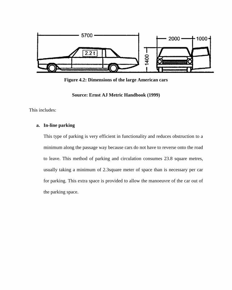
Figure 4.2: Dimensions of the large American cars
Source: Ernst AJ Metric Handbook (1999)
This includes:
a. In-line parking
This type of parking is very efficient in functionality and reduces obstruction to a
minimum along the passage way because cars do not have to reverse onto the road
to leave. This method of parking and circulation consumes 23.8 square metres,
usually taking a minimum of 2.3square meter of space than is necessary per car
for parking. This extra space is provided to allow the manoeuvre of the car out of
the parking space.
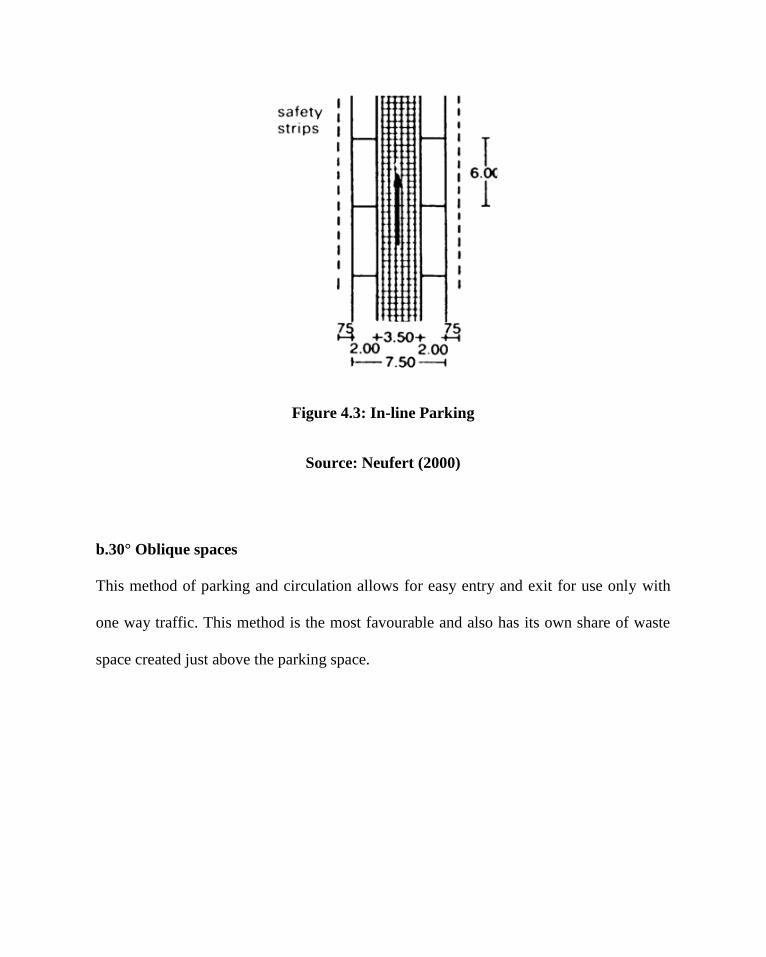
Figure 4.3: In-line Parking
Source: Neufert (2000)
b.30° Oblique spaces
This method of parking and circulation allows for easy entry and exit for use only with
one way traffic. This method is the most favourable and also has its own share of waste
space created just above the parking space.
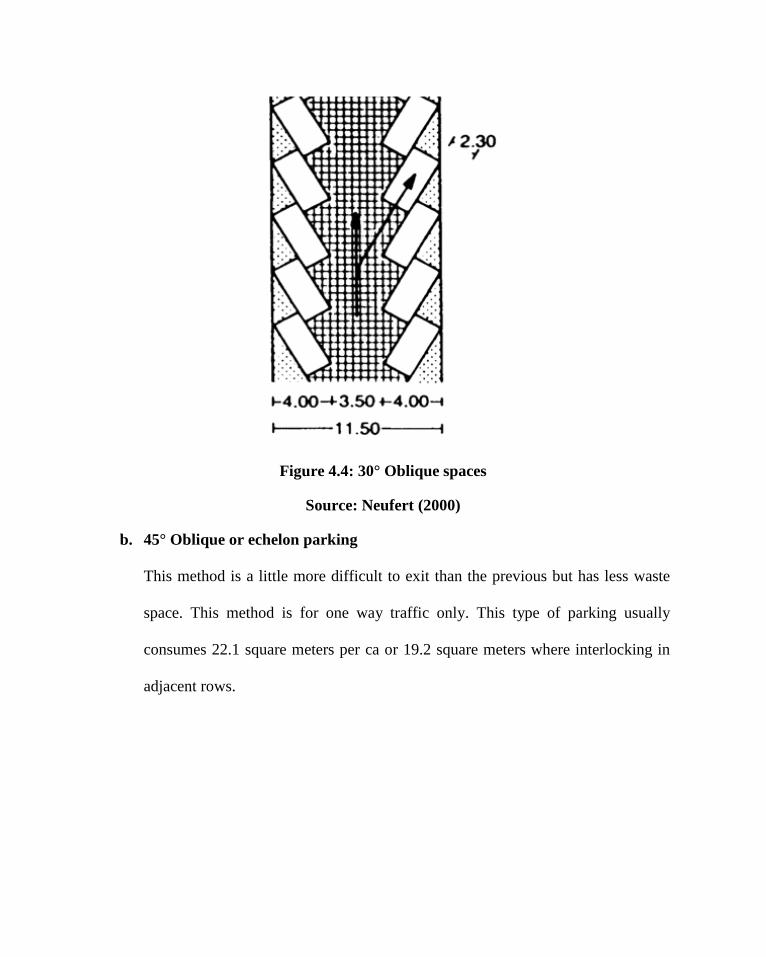
Figure 4.4: 30° Oblique spaces
Source: Neufert (2000)
b. 45° Oblique or echelon parking
This method is a little more difficult to exit than the previous but has less waste
space. This method is for one way traffic only. This type of parking usually
consumes 22.1 square meters per ca or 19.2 square meters where interlocking in
adjacent rows.

Figure 4.5 (a) 45° Oblique spaces
Source: AJ Metric Handbook (1999)
Figure 4.5 (a) 45° Oblique spaces
Source: Neufert (2000)
C. 60° Oblique echelon parking
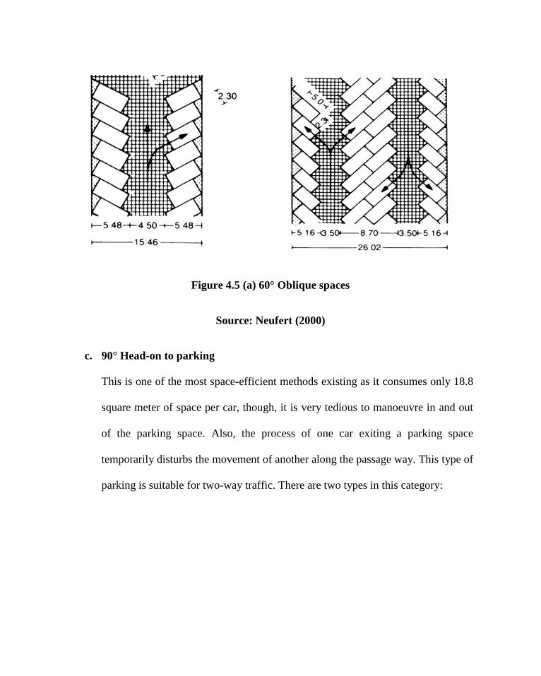
Figure 4.5 (a) 60° Oblique spaces
Source: Neufert (2000)
c. 90° Head-on to parking
This is one of the most space-efficient methods existing as it consumes only 18.8
square meter of space per car, though, it is very tedious to manoeuvre in and out
of the parking space. Also, the process of one car exiting a parking space
temporarily disturbs the movement of another along the passage way. This type of
parking is suitable for two-way traffic. There are two types in this category:

Figure 4.5 (a) 90° Head-on parking
Source: AJ Metric Handbook (1999)
The first category provides a parking space width of 2300mm. This
reduced space allowance consequently affects the width of the two-way
traffic road to allow for adequate manoeuvring. Here, the allowance for
the passage way is 6500mm.

Figure 4.5 (b) 90° Head-on parking with double passageway
Source: Neufert (2000)
The second category provides a parking space of 2500mm width. This increased
space allowance allows for a reduced passageway width of 5500mm while still
supporting adequate circulation and manoeuvring.

Figure 4.5 (c) 90° Head-on parking with minimum space for double passageway
Source: Neufert (2000)

Figure 4.5 (d) 90° Head-on parking with minimum space (extreme use)
Source: Neufert (2000)

d. 45° Angled parking
This type of parking is for one way traffic only.
Figure 4.5 (e) 90° Head-on parking with minimum space for double passageway
Source: Neufert (2000)
The table 4.1 below shows the space requirement to be provided for depending on the
angle of the parking spaces.

Table 4.1 Space requirement for various parking angles
Source: Neufert (2000)
4.2.2 CIRCULATION PATHS

Since space management is of paramount importance in this research work, it is then
necessary to properly analyze the circulation of the vehicles within the building as
circulation is also a space occupant within buildings.
For vehicles, there should be an efficient path around the car park to locate a space, then
to proceed quickly to the exit. Clear signing is required, usually combining ground route
markings and mounted signs.
For pedestrians, the location of exits, whether stairs or lifts should be visible from any
point within the car park. Standard green and white or illuminated signs must be
provided. Space is required around exit positions and pay machines safe from vehicle
flows.
4.2.1 Stairs and Lifts
The number and location of escape stairs is subject to minimum distances from
any point within the car park. They should be of generous width, open balustrade,
well lit (preferably with natural light), ventilated and fitted with glazed doors top
and bottom for user safety. Installation of lifts (average eight person size) is
required if there are two floors or more.
4.2.2 Vehicular circulation
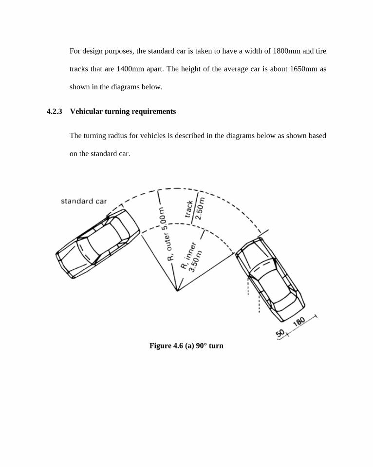
For design purposes, the standard car is taken to have a width of 1800mm and tire
tracks that are 1400mm apart. The height of the average car is about 1650mm as
shown in the diagrams below.
4.2.3 Vehicular turning requirements
The turning radius for vehicles is described in the diagrams below as shown based
on the standard car.
Figure 4.6 (a) 90° turn

Figure 4.6 (b) 360° or U-turn Figure 4.6 (c) 360° turn
Figure 4.6 (d) 3-Point turn
Source: Neufert (2000)
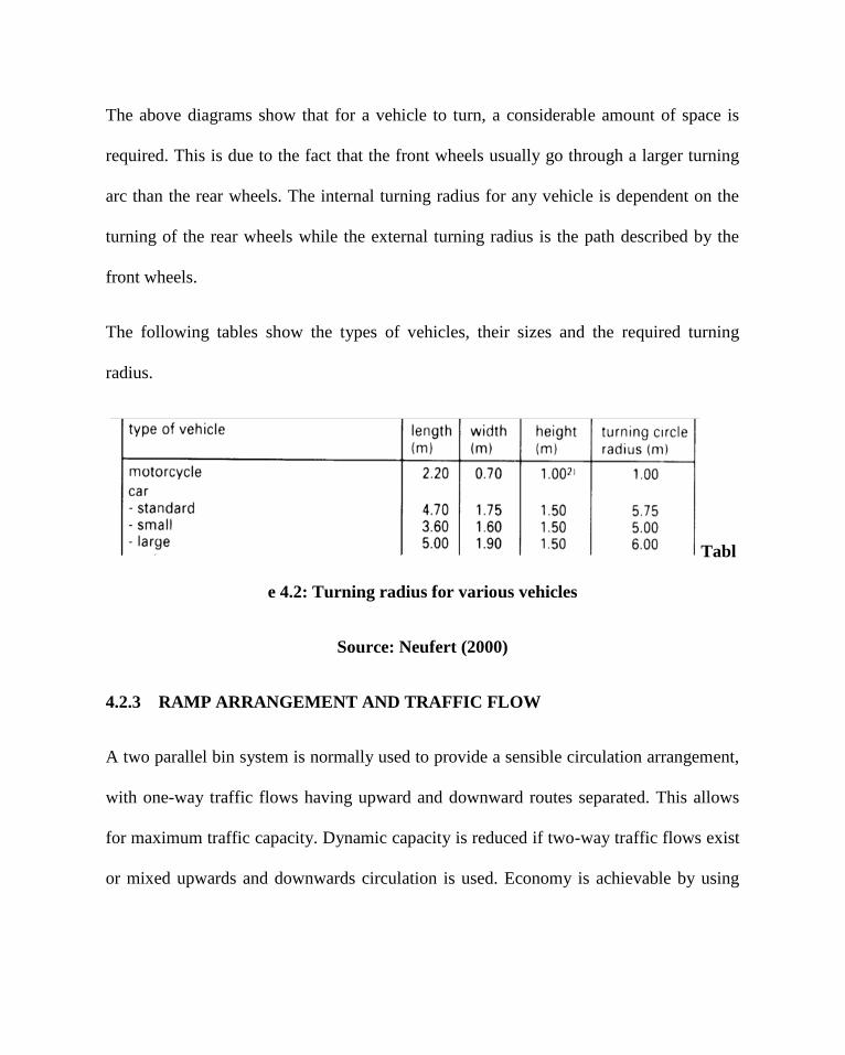
The above diagrams show that for a vehicle to turn, a considerable amount of space is
required. This is due to the fact that the front wheels usually go through a larger turning
arc than the rear wheels. The internal turning radius for any vehicle is dependent on the
turning of the rear wheels while the external turning radius is the path described by the
front wheels.
The following tables show the types of vehicles, their sizes and the required turning
radius.
Tabl
e 4.2: Turning radius for various vehicles
Source: Neufert (2000)
4.2.3 RAMP ARRANGEMENT AND TRAFFIC FLOW
A two parallel bin system is normally used to provide a sensible circulation arrangement,
with one-way traffic flows having upward and downward routes separated. This allows
for maximum traffic capacity. Dynamic capacity is reduced if two-way traffic flows exist
or mixed upwards and downwards circulation is used. Economy is achievable by using

the longest practicable aisle lengths. The downward routes should be short to expedite
exit, with upwards routes devised to give the best possible search patter for vacant stalls.
A number of different inter-floor ramps systems can be used to enable automobile to
transverse the approximate 3.0m elevation between parking levels. Some of these
systems provide separate and exclusive ramps, while others make use of continuous
sloping floors that accommodate both parked vehicles and inter-floor travel.
Ramps may be straight, curved, or a combination. No single ramp system is best for all
applications. The choice should be based on site shape and dimensions and parking
demand characteristics.
Double ramps result in a two-way traffic system. This should only be preferred when
there are extreme “rush hours” in a multi-storey car park, like in office car parks. Using
scissor ramps results in a one-way traffic system on the ramps, though incoming and
outgoing cars are directed along the same driving lane. The scissor ramps should have the
width of two parking spaces for more user friendliness. The longitudinal distance
between bearers and girders will be determined according to the dimensions of the
parking spaces. Normally, this distance corresponds to the width of two parking spaces.
The multi-storey parking in itself may take various design shapes, but basically consist of
a slab and column structure all through. When considering space management, it would
be very necessary to look into the economic width of ramps.

The width of the ramps is worked out according to the width of the parking spaces. For
one-way traffic the ramp will have the width of two parking spaces, for two-way traffic it
is the width of three parking spaces. Split-level parking is the most preferred ramp
system, because it offers the possibility to decrease the ramp length whilst still offering a
normal degree of slope. This guarantees an economical use of the parking space.
Ramp Dimensions in Different Storey Heights:
Figure 4.7 (a) Ramp slope for split level
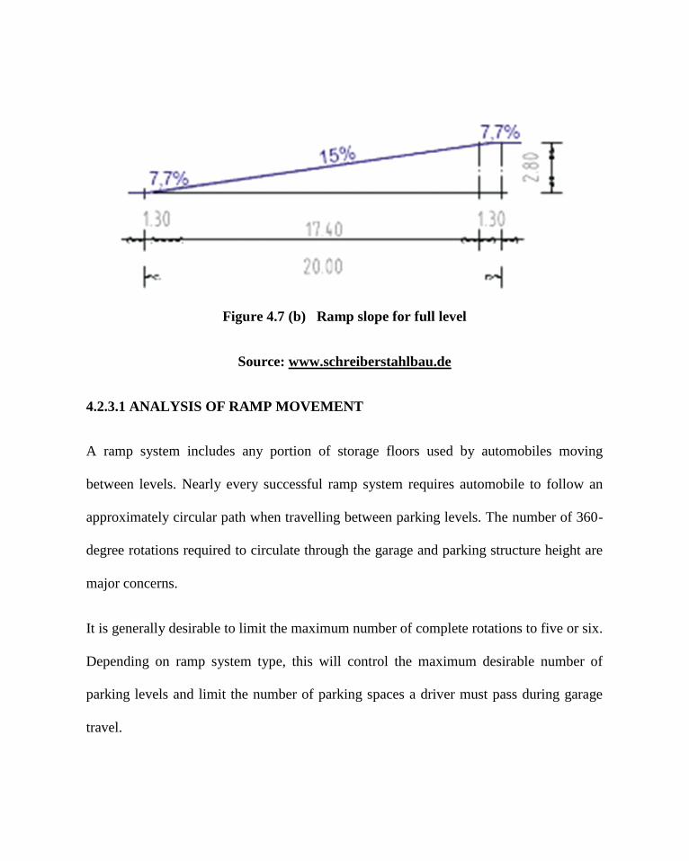
Figure 4.7 (b) Ramp slope for full level
Source: www.schreiberstahlbau.de
4.2.3.1 ANALYSIS OF RAMP MOVEMENT
A ramp system includes any portion of storage floors used by automobiles moving
between levels. Nearly every successful ramp system requires automobile to follow an
approximately circular path when travelling between parking levels. The number of 360-
degree rotations required to circulate through the garage and parking structure height are
major concerns.
It is generally desirable to limit the maximum number of complete rotations to five or six.
Depending on ramp system type, this will control the maximum desirable number of
parking levels and limit the number of parking spaces a driver must pass during garage
travel.

Drivers are sometimes distracted or disturbed by the awareness of the height when
travelling on upper parking levels, a condition that can be accentuated if parking levels
extend higher than adjacent buildings. To reduce driver distraction, parapet walls along
driving ramps should be designed to limit the driver’s view of surroundings outside the
parking structure.
Figure
4.8 (a) Full ramps with no loss of space (b) Spiral ramp car park
(c) Multi-storey structure with full ramps (d) Half-storey ramp car park
(Source: Neufert, 2000, p441)

Above shows various ramp systems for gaining access to different levels in multi-storey
car parks. The gradients of the ramps should generally not exceed 15°-20°. A horizontal
run of more than 5m must be included between an area carrying general traffic and ramps
with more than 5° gradient.
Typical arrangements for multi-storey floors include
4.2.3.1 SPLIT LEVEL LAYOUT
This arrangement is more widely adopted than the rest. It basically consist of two bins
arranged in such a way that adjacent parking levels are separated by half-storey height.
Short interconnecting ramps are use between levels.
Figure 4.9 Split level layout

4.2.3.2a One-Way Traffic Flow
Using scissor ramps will result in a one-way traffic flow on the ramps, though incoming
and outgoing cars are directed along the same driving lane. This is the usual construction.
Figure 4.10a Split level ramps with one way traffic

Figure 4.10b Split level ramps with one way traffic
Source: www.schreiberstahlbau.de
4.2.3.2b Two-way traffic
Double ramps result in a two-way traffic system. This should only be preferred when
there are extreme “rush hours” in a multi-storey car park, like in office car parks.
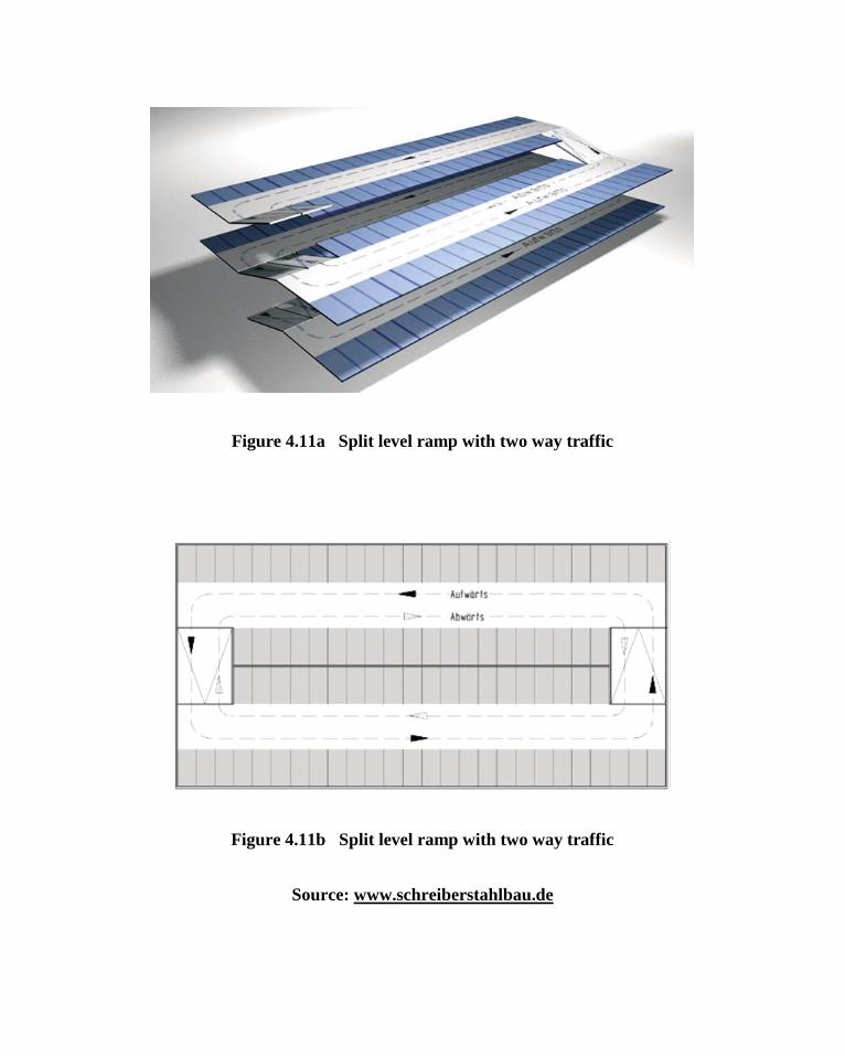
Figure 4.11a Split level ramp with two way traffic
Figure 4.11b Split level ramp with two way traffic
Source: www.schreiberstahlbau.de

4.2.3.2c Separate Traffic Flow
Here, the lanes for incoming and outgoing cars are separated. The number of parking
spaces, along which the incoming cars are led, is high; the traffic flow is simple and
clear.
Figure 4.12a Split level ramp with separated traffic flow
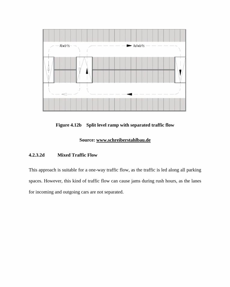
Figure 4.12b Split level ramp with separated traffic flow
Source: www.schreiberstahlbau.de
4.2.3.2d Mixed Traffic Flow
This approach is suitable for a one-way traffic flow, as the traffic is led along all parking
spaces. However, this kind of traffic flow can cause jams during rush hours, as the lanes
for incoming and outgoing cars are not separated.

Figure 4.13 Split level ramp for mixed use
Figure 4.13b Split level ramp for mixed use
Source: www.schreiberstahlbau.de
4.2.4 PARKING FOR THE DISABLED
Wherever public or private parking facilities are to be provided for, appropriate
arrangements for disabled people, as driver or passengers, should be made. At least 5% of
all car parking bays must be reserved for disabled visitors (Sport England, 2002). These
dedicated parking bays must comply with the minimum standards for disabled people.
They must be clearly identified, both on the bay surface and with a vertical sign
immediately adjacent to the bay. Disabled parking bays should be as close as possible to
the place that the user needs to go, and preferably under visual supervision to discourage
misuse by others. Bays should be at least 800mm wider than standard, to permit
manoeuvring of wheelchairs for transfer, and any kerbs should be ramped.
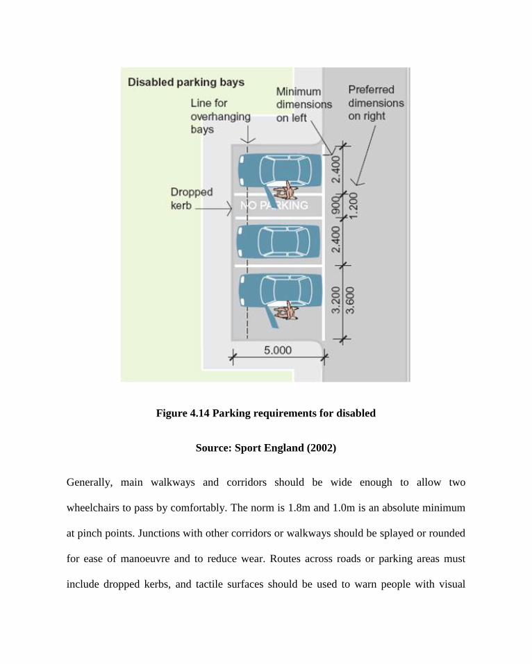
Figure 4.14 Parking requirements for disabled
Source: Sport England (2002)
Generally, main walkways and corridors should be wide enough to allow two
wheelchairs to pass by comfortably. The norm is 1.8m and 1.0m is an absolute minimum
at pinch points. Junctions with other corridors or walkways should be splayed or rounded
for ease of manoeuvre and to reduce wear. Routes across roads or parking areas must
include dropped kerbs, and tactile surfaces should be used to warn people with visual

impairment of impending dangers such as vehicular routes. Walkways should have a
maximum gradient of 1:20 with flat pauses at intervals of no more than 8m. If a walkway
is steeper it must be classified as a ramp. This means that a gradient between 1:20 and
1:15 should have a slip-resistant surface and handrails. A maximum gradient of 1:12 can
be used if the length is not greater than 5m.
Figure 4.15 Drop-off points for disabled
Source: Sport England (2002)
CHAPTER FIVE
5.0 THE SITE
The site for this project is cited according to the requirement for this design and the
available open space available in the area. The Lagos Island is and already congested
area, with scarcely any undeveloped punctuation. This site is an area marked out by the
planning authority for parking spaces and is currently in use.
5.1 GEOGRAPHY OF LAGOS STATE.
The city of Lagos lies in south-western Nigeria, on the Atlantic coast in the Gulf of
Guinea, west of the Niger River delta, located on longitude 3° 24' E and latitude 6° 27' N.
Lagos is the most populous conurbation in Nigeria with more than 8 million people
(Federal Republic of Nigeria Official Gazette May, 2007). Lagos State is bounded in the
North and East by Ogun State of Nigeria, in the West by the Republic of Benin, and in
the South by the Atlantic Ocean. It has four administrative divisions of Ikeja, Ikorodu,
Epe and Badagry. Territorially, Lagos State encompasses an area of 358,862 hectares or
3,577sq.km.
On this stretch of the high-rainfall West African coast, rivers flowing to the sea form
swampy lagoons like Lagos Lagoon behind long coastal sand spits or sand bars. Some

rivers, like Badagry Creek flow parallel to the coast for some distance before finding an
exit through the sand bars to the sea.
5.1.1 CLIMATE
The climate in Lagos is similar to that of the rest of southern Nigeria. There are two rainy
seasons, with the heaviest rains falling from April to July and a weaker rainy season in
October and November. There is a brief relatively dry spell in August and September and
a longer dry season from December to March. Monthly rainfall between May and July
averages over 300 mm (12 in), while in August and September it is down to 75 mm (3
inches) and in January as low as 35 mm (1.5 inches). The main dry season is
accompanied by harmattan winds from the Sahara Desert, which between December and
early February can be quite strong. The average temperature in January is 27°C (79°F)
and for July it is 25°C (77°F). On average the hottest month is March; with a mean
temperature of 29°C (84°F); while July is the coolest month. (BBC - Weather Centre -
World Weather - Average Conditions - Lagos )
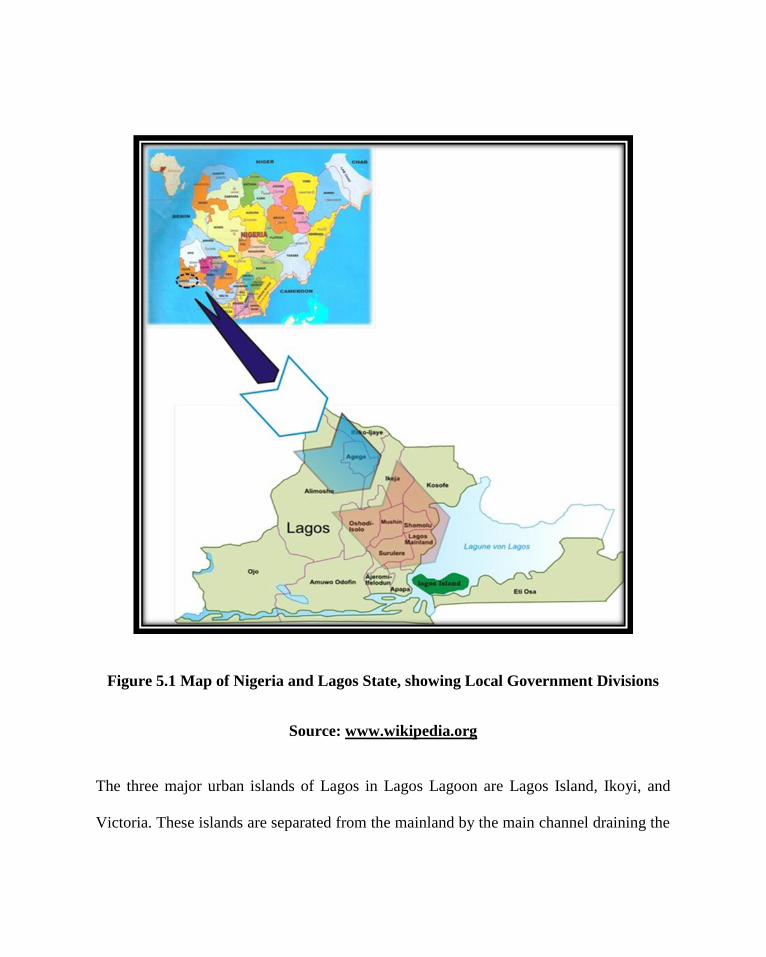
Figure 5.1 Map of Nigeria and Lagos State, showing Local Government Divisions
Source: www.wikipedia.org
The three major urban islands of Lagos in Lagos Lagoon are Lagos Island, Ikoyi, and
Victoria. These islands are separated from the mainland by the main channel draining the
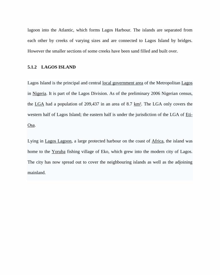
lagoon into the Atlantic, which forms Lagos Harbour. The islands are separated from
each other by creeks of varying sizes and are connected to Lagos Island by bridges.
However the smaller sections of some creeks have been sand filled and built over.
5.1.2 LAGOS ISLAND
Lagos Island is the principal and central local government area of the Metropolitan Lagos
in Nigeria. It is part of the Lagos Division. As of the preliminary 2006 Nigerian census,
the LGA had a population of 209,437 in an area of 8.7 km². The LGA only covers the
western half of Lagos Island; the eastern half is under the jurisdiction of the LGA of Eti-
Osa.
Lying in Lagos Lagoon, a large protected harbour on the coast of Africa, the island was
home to the Yoruba fishing village of Eko, which grew into the modern city of Lagos.
The city has now spread out to cover the neighbouring islands as well as the adjoining
mainland.
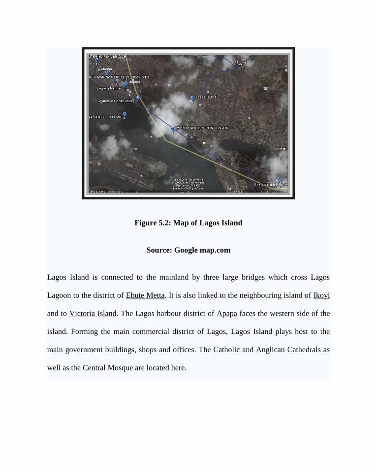
Figure 5.2: Map of Lagos Island
Source: Google map.com
Lagos Island is connected to the mainland by three large bridges which cross Lagos
Lagoon to the district of Ebute Metta. It is also linked to the neighbouring island of Ikoyi
and to Victoria Island. The Lagos harbour district of Apapa faces the western side of the
island. Forming the main commercial district of Lagos, Lagos Island plays host to the
main government buildings, shops and offices. The Catholic and Anglican Cathedrals as
well as the Central Mosque are located here.

Historically, Lagos Island (Isaleko) was home to the Brazilian Quarter of Lagos where
majority of the slave trade returnees from Brazil settled. Several families lived on Broad
street in Marina. (Website: http://www.lagosstate.gov.ng/)
5.2 SITE ANALYSIS
5.2.1 LOCATION
The site is located on the Marina Street by the Lagos lagoon on the Lagos Island. Lagos
Island is the principal and central local government area of the Metropolitan Lagos
covering an area of 8.7 km². The LGA only covers the western half of Lagos Island; the
eastern half is under the jurisdiction of the LGA of Eti-Osa. Forming the main
commercial district of Lagos, Lagos Island plays host to the main government buildings,
shops and offices. The Catholic and Anglican Cathedrals as well as the Central Mosque
are located here.
Figure 5.3: Map of marina
Source: Google map.com
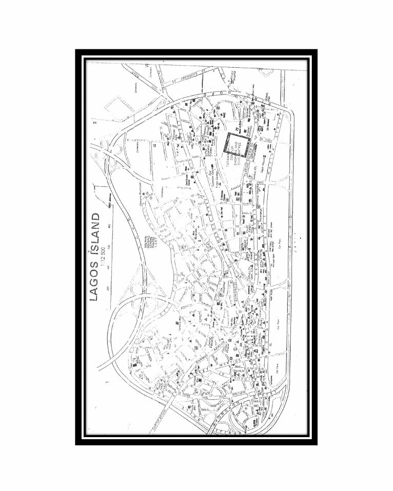

Figure 5.4 Map of Lagos Island
Source: Lagos Island Local Government (2007)

5.2.2 ACCESSIBILITY
The site of the project is opened to Marina Street and has short connecting routes with
Broad Street. Both vehicular and pedestrian movements are profound around the site and
is easily accessible from all the high rise buildings with an average walking time of 4
minutes. Marina street, which connects the site is also open at both ends, one end having
access to the main Ring Road.
Lagos Island is connected to the mainland by three large bridges which cross Lagos
Lagoon to the district of Ebute Metta. It is also linked to the neighbouring island of Ikoyi
and to Victoria Island. The Lagos harbour district of Apapa faces the western side of the
island.
5.2.2.1 HUMAN TRAFFIC
Marina Street is very busy, continuously bustling with high human traffic constantly
moving along the streets. This is because of the vast variety of commercial activities that
takes place here. At peak hours, the sidewalks are maximally utilised by pedestrians,
because of the connection of Marina street to the bus stops and other exit points.

Plate 5.1 View of the busy Marina Street
Source: Field Survey (2008)
5.2.3 DRAINAGE
The site has no natural relief drainage as it is already in steady use and has a generally
flat topography. Though, it has already has some man-made drainages by the sides of the
road.
5.2.4 SOIL TYPE
The soil type on the site is loose lagoon sharp sand and of natural inability to retain water.
This soil has loose grains and generally tiny particles and therefore classified as sandy

soil. Due to the low strength of sandy soils, it would be of necessity to make use of a
good raft foundation or piles for high rise buildings, as the soil would not adequately
support multi-storey structures all by itself.
5.2.5 STREET CHARACTER
All the buildings along the Marina street are high rise with an average of 12 storey. This
character is indicative of a central business district for which this project is perfectly
suited for.
5.2.6 ELECTRICITY AND WATER SUPPLY
The street is well equipped with all electricity facilities, from poles to transformers,
though, due to the erratic supply of electricity in Nigeria and as a need for backup, all
buildings in this area have their own private power generating plant.
5.2.7 ROADSIDE TRADING ACTIVITIES
A broad view down Marina and Broad Street cannot omit the strong presence of roadside
petty traders. These people have found their businesses lucrative – selling goods to the
ever busy office workers, especially after work hours, shortly before they retrieve their
cars around the existing parking facilities.
These traders trade in almost any thing, from clothing to food, stationery, art etc.

Plate 5.2 different view of the busy activities in Marina Street
Source: Field Survey (2008)
5.3 PHYSICAL FEATURES
5.3.1 Temperature
Lagos is a warm place with little change from month to month. It has the warmest months
between February and April and the coolest from July to August.

Nigeria can be classified into four major climatic zones for which Lagos state falls into
zone 4 – Subequatorial south which is a zone of warm humid climate.
Figure 5.5: Map of Nigeria showing the various Climatic zones.
Source: Iloeje (1977)
This comprises areas of mean daily maximum dry bulb temperature during the dry season
exceeds or equal 30°C and relative humidity lies between 70 to 100%. The daily range of
temperature is less than 8°C.
5.3.2 Rainfall
Lagos climate generally has a high average rainfall during the year at 1185mm. Records
over the years have shown that the average rainfall each year fluctuates. Lagos has two
main seasons, the dry season (from November to February) and the wet seasons (from
March to October) when high rainfalls are experienced.

Figure 5.6 Map of Nigeria showing the Rainfall distribution across regions
Source: Iloeje (1977)
5.3.3 Soil type
Generally, Lagos has a sandy soil. This is characterised by loose sand grains and tiny
particles. Some areas have alluvial soils which are as a result of its proximity to the
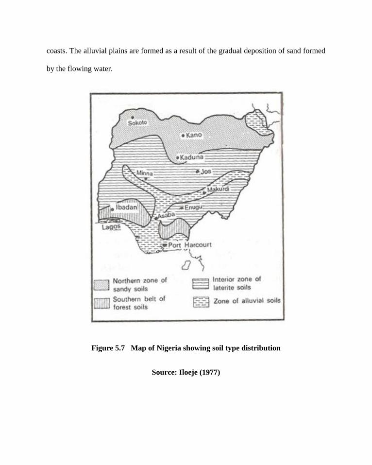
coasts. The alluvial plains are formed as a result of the gradual deposition of sand formed
by the flowing water.
Figure 5.7 Map of Nigeria showing soil type distribution
Source: Iloeje (1977)

Figure 5.8 Climates and Daylight Chart for Lagos, Nigeria
Source:http://www.climate-charts.com/Countries/Nigeria.html
5.3.4 Humidity
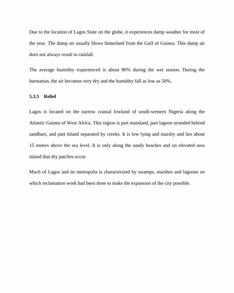
Due to the location of Lagos State on the globe, it experiences damp weather for most of
the year. The damp air usually blows hinterland from the Gulf of Guinea. This damp air
does not always result to rainfall.
The average humidity experienced is about 80% during the wet season. During the
harmattan, the air becomes very dry and the humidity fall as low as 50%.
5.3.5 Relief
Lagos is located on the narrow coastal lowland of south-western Nigeria along the
Atlantic Guinea of West Africa. This region is part mainland, part lagoon stranded behind
sandbars, and part Island separated by creeks. It is low lying and marshy and lies about
15 meters above the sea level. It is only along the sandy beaches and on elevated area
inland that dry patches occur.
Much of Lagos and its metropolis is characterized by swamps, marshes and lagoons on
which reclamation work had been done to make the expansion of the city possible.
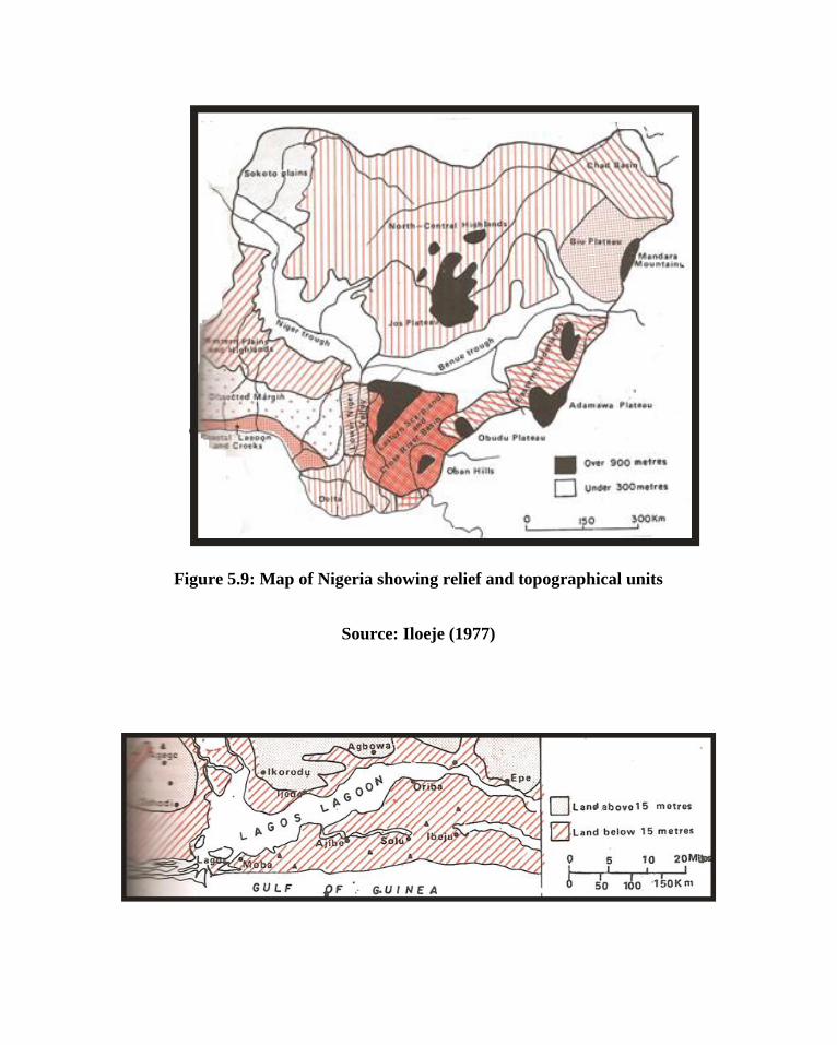
Figure 5.9: Map of Nigeria showing relief and topographical units
Source: Iloeje (1977)
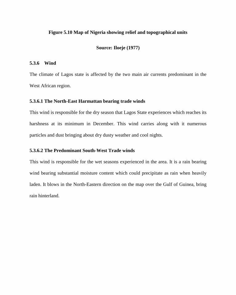
Figure 5.10 Map of Nigeria showing relief and topographical units
Source: Iloeje (1977)
5.3.6 Wind
The climate of Lagos state is affected by the two main air currents predominant in the
West African region.
5.3.6.1 The North-East Harmattan bearing trade winds
This wind is responsible for the dry season that Lagos State experiences which reaches its
harshness at its minimum in December. This wind carries along with it numerous
particles and dust bringing about dry dusty weather and cool nights.
5.3.6.2 The Predominant South-West Trade winds
This wind is responsible for the wet seasons experienced in the area. It is a rain bearing
wind bearing substantial moisture content which could precipitate as rain when heavily
laden. It blows in the North-Eastern direction on the map over the Gulf of Guinea, bring
rain hinterland.


Figure 5.11 Site analysis
Source: Author’s Research (2008)


Figure 5.12 Site Existing Features
Source: Author’s Research (2008)
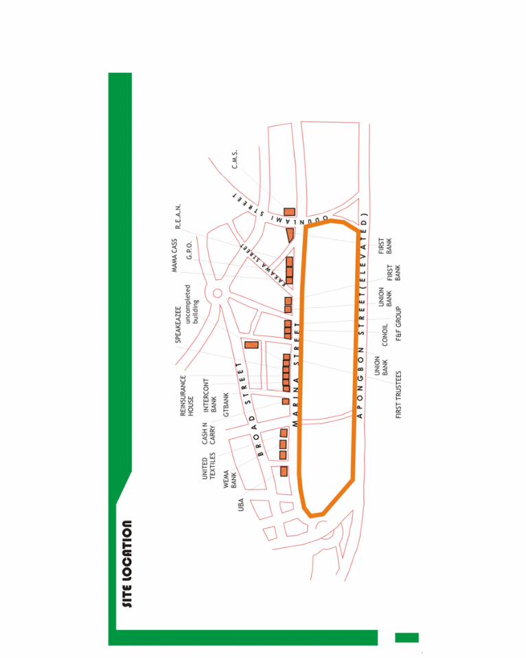

Figure 5.13 Site location and Existing buildings
Source: Author’s Research
CHAPTER SIX
6.0 GENERAL DESIGN CONSIDERATION
As has already been discussed, a good parking system helps to clear the urban spaces of
the indecency and waste of large areas of open land being daily converted to parking
spaces that are not aesthetically pleasing with reduced functional efficiency. The overall
increasing population of Lagos state over the past years, with the attending increase in
business activities within the Lagos Island central business district, basically within high
rise buildings along the Marina and Broad streets led to the execution of certain
measures. Under the United Nations standard of rating, Lagos state is to be classified as a
Megacity with its population of 17,552,942. The United Nations also estimates that at its
present growth rate, Lagos state will be third largest mega city in the world by 2015 after
Tokyo in Japan and Bombay in India.
6.1 CHIOCE OF SITE LOCATION
The Lagos State government after analysing these alarming statistics and with the rate of
decline in the city decided to launch a series of individual city rejuvenation programmes
which are to touch areas such as transportation and urban planning.

Lagos Island, being at the hub of the Lagos economy has grown in population and level
of prosperity over the years to a population of 859,849. The number of business operating
on the island has also seen great increase with the attending increase in the work force
and the need for transportation to and from their work places. This has gradually led to
the inability of the existing car parking spaces to accommodate the car users and the
gradual conversion of large open spaces into car parks creating an ugly urban experience
in these areas.
Attempts have been made previously to begin a multi storey car park projects for the
Marina. In front page publication in the Financial Times of August 30th
2007, the
chairman of the Lagos Island Local Government Council announced that construction
would soon begin on a N300,000,000 'Multi-storey car park' structure on the Marina
projected to accommodate 4500 cars. The announcement associated Messrs Bouygues
Construction with this project, possibly as a turnkey contractor (David Aradeon, 1996).
The duty of the architect that differ him from the engineer is his ability to make his
inventions enhance the social life of the people’s everyday life. As such, it would be very
inappropriate to have a rigid structure just serving one function, but rather versatile to
accommodate facilities that would make life more sociable and functional for human
while meeting its aesthetic demands on the outlook. In serving these, the need for other
public space arises.
6.2 DESIGN REQUIRMENTS

Parking as part of an overall transportation system is one of the crucial issues of our
times. As the number of automobiles increases exponentially, the need to house them in
close proximity creates a challenging design problem. Although car parks can take
many forms as stand-alone or part of a mixed-use structure, self-park or valet, and
automated in urban or rural settings, all car parks should seek to meet the following
basic criteria:
6.2.1 Functional Requirements
The car park or lot must foremost deal with the Functional/Operational need - as in
providing for safe and efficient passage of the automobile. This is a very complex
challenge as automotive, engineering and traffic issues relative to site locations must be
integrated to create the appropriate solution. Therefore designing the parking garage
requires an integrated design approach of many professionals. Parking has often been
reduced to the construction of the most minimal stand-alone structure or parking lot
without human, aesthetic or integrative considerations. This has given parking a poor
public perception and has frequently disrupted existing urban fabric. However, many
architects, engineers, and planners have envisioned and constructed far more complex,
aesthetic, and integrative structures. This should be the goal of good parking design.
The car park should account for the complex spatial needs of the driver and the
automobile:
The size, height, and turning radius of current automobiles as well as past and
future trends of automobile size and statistical quantity must be taken into
account these are called parking geometries.

There are many ramp design configurations and different ones are appropriate
for the primary purpose of the facility to insure that your intended use is
compatible with ramp design.
The streets surrounding the garage and their traffic flow must be taken into
consideration when planning entrances and exits and deciding on ramp designs.
The entrances and exits are very important to the smooth functioning of the
garage, with the type of use again determining the length from the opening and
placement of the entry booths, as well as the quantity of entrances and exits.
The type of equipment and the necessity of a booth and office are also
determined by the garage use.
Optimizing site potential, by choice of site and its relationship to walking,
driving, other transportation linkages and good design opportunities.
The operation and maintenance of a garage is very critical. Revenue control
equipment and other issues related to the smooth functioning of the garage must
be taken into account during the design process.
Provide for appropriate work space for the staff, such as cashier and monitoring
equipment.
Provide an area or room for the storage and maintenance issues. This area
should be heated/air-conditioned and contain a mop sink.
Accommodate technological tools for future upgrades of operational systems
and facility expansion.
Plan for a back up power system.
Ventilation is an issue within some types and some areas of parking garage
design. New technologies are increasing the effectiveness in design and
monitoring of these areas for concern. Natural ventilation is always a good
method however detailed study is required in some areas and types of parking
garage design to determine its effectiveness.
6.2.2 Structural Integration
The efficient integration of structure is crucial to maximum functioning of the garage:
The parking garage is typically an exposed structure and must be designed to
withstand all aspects of environmental conditions.
There are ideal structural bays that allow for maximum number of parking
spaces and flow of automobiles dependent upon site and structure.
Cast in place concrete, pre-cast concrete and structural steel can be used for the
structural design.
Typical construction issues such as natural hazards in the location of
construction apply and compound the solutions in designing a structure that is
completely exposed to the weather and constant movement from automobiles.
Size and length of some structures compound the expansion and contraction
issues already of key importance in garage design.
The surface of the "floor" of the garage is important to slippage issues as one
must always design a garage as a fully exposed building for the safe use by both
the automobile and pedestrian.
Drainage and floor slope is very important, as ponding water can create long
term maintenance problems.
6.2.3 Safety and Security
Safety and security of the people using the garage are of paramount importance:
Open, glass stairwells and glass-backed elevators.
Security devices such as video, audio and emergency buttons that call into the
booth or local police station.
Public telephones
Eliminate potential hiding places, such as under open stairs.
Handicap accessibility with vehicles close to stair and elevator cores having a
direct path to key movement patterns of the garage.
To avoid carbon monoxide build-up, air flow is adequately designed for through
mechanical and/or natural ventilation.
Non-slip floor surface
Design for the points of intersection between man and the automobile for
adequate safety of movement.
Energy efficient lighting is very important in garage safety but can pose
problems with spillage out of the garage onto neighbouring communities. A
balance between day lighting, interior lighting and exterior control can be
addressed in many ways on the exterior design of the façade while providing
adequate lighting within. Lights should be vandal resistant and easy to maintain.

6.2.4 Signs and direction
Color-coding, numbering, visual cues, music, and even machines for marking
your ticket with your exact location to locate your car for easy retrieval
Locate signs in areas where driver can read in a timely fashion.
Clear, simple, and direct messages.
Floor coding can be useful
Signage should locate all major internal pedestrian access points as well as
external major roads and buildings.
6.2.5 Aesthetics
Aesthetics of garage design has become very important to communities across the
country:
Recently garage design has become part of an architectural style of the
surrounding architecture, respecting the language of design and using the design
process.
The historic preservation movement was one of the key issues in garage design
as garages were needed to revitalize dense older urban fabrics without
destroying the architectural context. Many excellent examples can be found
across the country solving these contextual issues.

The Parking garage itself is now also part of the historic preservation movement
as some older existing structures can and should be designated for preservation.
The Parking Facility has played an important role in design evolution
throughout its history often being the leader in many crucial design issues; it is
truly a unique and important civic building. Perhaps one of the most important
design laboratories of the 20th century it has become the gateway to our
buildings and cities.
Maintain the urban street front by having the sidewalk condition of the garage
contain stores or provide a safe and pleasant walk experience.
Using landscaping and changes in architectural materials forms, and scales to
enhance the garage façade along the street. Use landscaping to shied and
enhance parking lot design.
Architecturally breaking down the scale of the large structure along its façade.
Designing beautiful stairs and elevator cores to enhance the community and
walking experience.
6.2.6 Integrated and Mixed-Use Design
Multi-Storey car parks are often connected to other uses:
The garage has always been a mixed-use structure combining and often
connected with all other building types.

Plan for any loading or unloading conditions required by mixed-use, so as not to
interfere with garage traffic.
Separate roofing and structural system for any human-occupied space within
garage.
Provide for simple and well-designed movement systems for pedestrian and
automobiles.
Many garages are combined with almost any use imaginable such as a playing
surface on the roof requiring green architecture, so enjoy the possibilities of
integrating a fully functional structure requiring many technological advances.
Surface parking lots can be designed to become mixed-use plaza spaces.
The garage has often in its history been part of a multi-modal system linking
different forms of transportation.
6.2.7 Environmental Issues
The car in its' early years was the environmental saviour of our cities and towns,
eliminating animal waste and carcasses in our streets, part of the cause of many health
and environmental hazards at the beginning of the century. But as their numbers and use
have increased dramatically they have become part of the current environmental
problems. New fuel sources for the automobile can eliminate these air pollution hazards
and automobile manufacturers are working on the solutions. Parking lots as large areas
of paved surfaces contribute to warming trends in cities and have altered local weather
patterns. Large areas of paving that have absorbed oils, fuels, road salts, and other
materials contribute to problems in water runoff and pollution. Garages and parking lots
need to address these issues exploring porous paving in lots and best practices of water
run-off issues.
6.3 CONSIDERATION BEFORE THE CONSTRUCTION OF MULTI-
STOREY CAR PARKS.
a. Proximity
Annual customer surveys indicate proximity to destination is by far the dominant issue in
the parking decision of users. All other aspects of the car park, including design, are
secondary to convenience, but this is no excuse for poor design.
b. Accessibility
The car park should be easy to find in the street network. The entrances should be located
by main roads where they can be more easily utilised. Where entrances are hidden there
is an absolute requirement for high visibility on-street signage taking motorists from the
street directly to the car park entrance. Similarly for departing cars, signage should lead
them smoothly back to the main streets with clear directions to major landmarks or
destinations to avoid disorientation.
External signage should indicate where the entrance is and once at the entrance the
control system should be self-explanatory. The car park should be easy to enter and
should be clear from the earliest possible point.
c. Navigation and way finding
Navigation of the structure and location of vacant spaces should be easy for all motorists.
Clear internal signage and floor markings directing cars to "parking" are fundamental but
frequently neglected features of new car parks. It is recommended to have fluorescent
lamps as directional aids e.g. along the spine of the decks. They should be installed
lengthways while at crossing points/ramps (min. 3m wide), junctions etc., and they can
be at right angles to the traffic. The biggest challenge here is to convince structural
engineers/developers of the merits of column free construction in car parks. Structural
columns and mass concrete walls make a car park interior into a nightmare for many
drivers
d. Pedestrian circulation
Pedestrian routes, walkways, stairways, lobbies, lifts (min. 2 x 13 person) should all be
easy to follow and use. It is easy to forget that for every car that park in a facility, there
are likely to be twice as many pedestrian movements. These pedestrians are fragile
compared to the cars they arrived in and may have young children, infants in prams or
hyper active teenagers, or they may be older or mobility impaired; returning to their cars,

they may have heavy shopping in bags or trolleys. All of these factors have to be
considered. In half deck designs it is common to have lifts and stairs on one side of the
structure only with the consequence that patrons have to navigate from one half decks to
another and frequently this is done via the vehicle ramps.
e. Lighting
A major issue for pedestrians is the impact of design on their sense of well being and
personal security. It is easy to address many of the facets that impact on this lighting
levels are critical, with a minimum standard of 100 lux at 1m now the norm. Lighting
levels at lobbies and entrances/exit should be a minimum of 250 lux.
f. Safety and security
It is recommended that all doorways be of clear glass so that patrons can see through the
obstacle. Lift lobbies should be enclosed only as a last resort and then with glass filled
walls/doors. Lift doors should be of glass. Stairways accessible to the public should be
wide and bright. All pedestrian routes should be clearly signposted in both directions and
levels should be clearly numbered.
The lobby should be clean, clear and bright with no corners or alcoves where
troublemakers might hide. The lobby should have close contact with the staff office and
be overlooked at all times.

g. Internal finishes
Floors should be tamped or stippled concrete with only pedestrian walkways painted.
Painted floors are impossible to maintain to any high standard. Walls, columns, doors and
ceilings should be painted and decorated to brighten the car park. Walls should be painted
black to about 450mm to camouflage soot marks from car exhausts.
Seek the provision of well located car parking spaces, multi storey car parking being the
preferred option and to ensure that adequate and convenient car parking spaces are
provided
a. To ensure, through price control measures, that the city centre car parking
spaces are for short stay purposes;
b. To reserve suitable locations in the Environs of the City for park and ride
facilities
c. To ensure suitable parking for long-stay;
d. To locate strategically disabled car-parking bays.
h. Pedestrian and ramp edge restraint specification
Restraints should be provided to a height of 1.lm above the highest foothold. This retains
the current requirements for pedestrian guards and ramp guards. These should restrain
1.5kN/m on the balustrade handrail, 1.5kN at any point location, should resist the passage
of a 100mm diameter ball, and be of adequate height to restrain children. The
specification clarifies the need to take account of the attraction for children of climbing
on vehicle restraints. (Jolly, 2001).
i. Stairwell edge protection
The same requirements should apply to stairwell edge protection, as at the edge of the
deck. This recognizes that the risk to pedestrians within stairwells of vehicles or
dislodged masonry falling on them is the same as at the edge of car park decks. (Jolly,
2001).
6.4 DESIGN BRIEF
To design a multi storey car park that would park 2500 cars conveniently and add social
and aesthetic values for the Lagos State Government.
A detailed field study of the existing problems in the Marina area has led to the
development of the need for certain spaces within the multi-storey car park to
accommodate certain activities. These activities include:
MULTI-STOREY CAR PARK
1. The parking stalls
2. Parking stall for the disabled
3. Auto-mechanic workshop
4. Vulcanizer’s workshop/garage
5. Security posts
6. Ticketing areas
7. Stairwell
8. Lifts
9. Ramps
10. Conveniences
PUBLIC AREAS
1. concourse
2. smoker’s lounge
3. periodicals
4. management offices
5. lettable shops and offices
6. restaurant/canteen
7. snack bar
8. drinks bar
9. conveniences
6.4.1 Concourse

This space is to serve those who have to wait for one reason or the other within the car
park. This may be especially for drivers who have to hang around during their work
hours. They could relax and keep busy in these areas instead of hanging around.
6.4.2 Smokers’ lounge
When designing any public building, a place should be kept for smokers. The space
should be well furniture with sofas and should include a bar. It should also have spaces
for board games and pool.
6.4.3 Periodicals
This is an area where people can purchase and read newspapers, magazines and journals.
This space should be designed with shelves and racks to display the sales items and a
lounge for people to sit and read various materials. It should be located around the main
concourse, but sectioned off by glass partitions, giving a through view into the concourse.

6.4.4 Management offices
These are offices to be used by the staffs in charge of the car park facility. These offices
should include a head security office, manager’s office, secretary, asst. Manager, and
maintenance office. Usually, the space requirement for an office ranges from 9.0m2 to
24m2
6.4.5 Lettable shops
These shops are designed to be rented out. They would be designed to have good views
and accessibility from the concourse and outside the building as marketing for the goods
to be sold.
6.4.6 Restaurant/Canteen
Within the existing parking space are small eateries. This serve the drivers who await
their bosses and the bosses during their break and for those who may like to eat after the
day’s work before their drive home.
The restaurant is a very important feature in any public building and should be ideally
located to have a good visual relationship with the public spaces and concourse for the
purposes of self advertisement and convenience. The restaurant would have two sections,
and area that would be serviced by waiters and another which would take the form of a
cafeteria layout, having a servery and ticketing space.

The four seat table arrangement shown below would be used in the restaurant because of
the convenience and ease of movement it affords.
Figure 6.1 Seating analysis for Restaurant
Source: Neufert (2000)

Figure 6.2: Functional layout of a small restaurant
Source: Neufert (2000)
The capacity of a restaurant kitchen is basically dependent on the number of customer
seats, customer expectations and the proportion of raw materials which have to be freshly
prepared. Usually, a restaurant kitchen uses up between 15 – 35% of the overall
restaurant space or more depending on the storage requirement and cooking variety.
Considering a small restaurant with seating capacity of 80, the amount of spaces for
various kitchen functions can be calculated using the table below:

Table 6.1 Analysis of kitchen space requirement

Source: Neufert (2000)
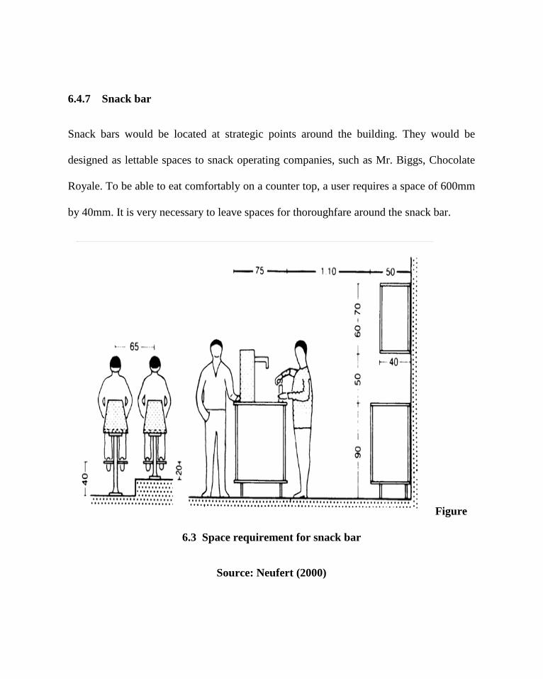
6.4.7 Snack bar
Snack bars would be located at strategic points around the building. They would be
designed as lettable spaces to snack operating companies, such as Mr. Biggs, Chocolate
Royale. To be able to eat comfortably on a counter top, a user requires a space of 600mm
by 40mm. It is very necessary to leave spaces for thoroughfare around the snack bar.
Figure
6.3 Space requirement for snack bar
Source: Neufert (2000)

6.4.8 Drinks bar
These are bars which are to sell alcoholic drinks. They would be located at reserved
areas, not completely open to the concourse. The space requirement for the drinks bar can
be estimated on an almost equal basis to that for the snack bars. This is because of the
similarity in counter top and stool dimensions.
6.4.9 Conveniences
All conveniences would be located at areas with high pedestrian traffic to prevent acts of
crime in and around it.
6.4.10 Parking bays
This is the area marked out within the building where cars are to be parked. Field
estimates require the facility to be able to park above 2,500 cars. The estimated
requirements for disabled people in parking lots is usually 5%, as such 600 parking
spaces would be required to serve the disabled persons.
6.4.11 Security post
These are spaces which are to be designated as points where security personnel would be
positioned. This space is supposed to be at a vantage point visually so as to see a wide
area of the parking. This space should be able to accommodate a chair, a table to write
upon and a hanging rack for coveralls/uniforms.

6.4.12 Stairwells and Lifts
These are spaces designated for vertical movement within the building structure. They
are to be well distributed around the building for ease of movement around. The
stairwells are to be well lighted and open to prevent crimes. Average stair riser height
should not exceed 150mm as the building has mixed users. The building facility would
have rush hour periods on an almost daily basis on various hours and as such, the
stairwells must avoid turn along their lengths. This makes wide straight flight stairs the
most suitable for use. Also, because of the rush hour traffic, the stairs must be wide
enough to be able to accommodate at least three people walking side by side. As shown.

Figure 6.4: Stair Case with Three People Climbing Side-By-Side
Source: Neufert (2000)
6.4.13 Ramps

This is the space which provides vertical transport within the building for the vehicles. It
should slope at about 15% and link directly with from one level to another or an
intermediate level.

6.4.14 Conveniences
This must be located on the ground floor. Avoidance of this space on the upper floors is
generally for security reasons. The location would be along the generally busiest area
where there is constant human activity for safety. Experience over time has shown that
unless the toilets are staffed and closely monitored they become magnets for a wide range
of anti-social activity. A key controlled toilet operated in the way that many petrol
stations do is an option except where it is in a public area.
6.4.15 Lettable shops and Offices
These shop spaces are to accommodate activities that hang along the street. These
activities thrive in this area because of the patronage of the workers who use the vehicles
car parks. Some may want to make a brief shopping or chore immediately after work
each day. It would therefore be very convenient to locate such service and goods, by
creating spaces for them.
6.4.16 Auto-Mechanic workshop
The auto-mechanic workshop normally must be able to cater for at least six vehicles at a
time and requires only a front access. This workshop would be capable of carrying out
day to day maintenance and repairs, including and equivalent of MOT testing, standard
servicing and body repairs. They are not expected to replace engines or crankshafts or do

other heavy repairs and/or body works. Finishes for workshop space must be use robust
and durable floor non-slip surfaces.

SPACE PROGRAMMING
Space description Area (m2) quantity Total (m
2)
Parking stall 22.1 2,375 52,487.5
Disabled parking 25.6 125 3,200
Auto-mechanic 1 132.6
Car wash 1 132.6
Vulcaniser 1 44.2
Security posts 4 8 24
Ticketing
Stairwell 8.64 12 103.68
Ramps 60.9 10 609
Conveniences
Concourse 1 300 300
Smokers’ lounge 28
Periodicals 28
Management offices 12 5 60
Lettable shops 54 10 540

Restaurant/canteen
Dining area
convenience
Kitchen
Preparation area
Wet storage
Dry storage
Day store
Waste disposal
Changing rooms
Dishwashing
Waiters’ area
1.495
300
448.5
180
12
75
3
12
1
18
Snack bar 50 1 50
Drinks bar 50 1 50
TOTAL 69532.98
Table 6.2: space programming table
Source: Authors’ research (2008)
6.5.1 EQUIPMENT AND OPERATIONAL REQUIREMENTS
6.5.1 Close circuit cameras

This is a very important feature in car parks. It helps to monitor the parking areas to help
prevent crimes. Lot crimes are known to be committed in car parks on a daily basis.
Statistics show that the mere presence of CCTV reduces crime by 35%. Cameras would
be mounted at angles which would give a wide range of visibility. All cameras would be
connected to the security office where images are being recorded and stored in safes.
6.5.2 Electronic parking system
The multi-storey car park is going to be designed as an automated parking system. The
automation would be in the ingenious use of electronic systems to inform the users before
entering the parking bays of available car parking spaces available. The system would
also be able to indicate the available parking stall which are vacant and allocate spaces to
coming users. This automation helps to reduce the time usually spent in most car parks
searching for a vacant stall. The user simply identifies the vacant stall and moves straight
on to park.
6.5.3 Electronic ticketing system
The ticketing system to be used would be completely electronic. It would function in
such a way that it calculates the actual time spent on the parking stall and bill the user as
required. This electronic system would also help to check irregular parking by billing
fines from the users or refusing them exits.
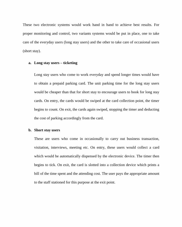
These two electronic systems would work hand in hand to achieve best results. For
proper monitoring and control, two variants systems would be put in place, one to take
care of the everyday users (long stay users) and the other to take care of occasional users
(short stay).
a. Long stay users – ticketing
Long stay users who come to work everyday and spend longer times would have
to obtain a prepaid parking card. The unit parking time for the long stay users
would be cheaper than that for short stay to encourage users to book for long stay
cards. On entry, the cards would be swiped at the card collection point, the timer
begins to count. On exit, the cards again swiped, stopping the timer and deducting
the cost of parking accordingly from the card.
b. Short stay users
These are users who come in occasionally to carry out business transaction,
visitation, interviews, meeting etc. On entry, these users would collect a card
which would be automatically dispensed by the electronic device. The timer then
begins to tick. On exit, the card is slotted into a collection device which prints a
bill of the time spent and the attending cost. The user pays the appropriate amount
to the staff stationed for this purpose at the exit point.
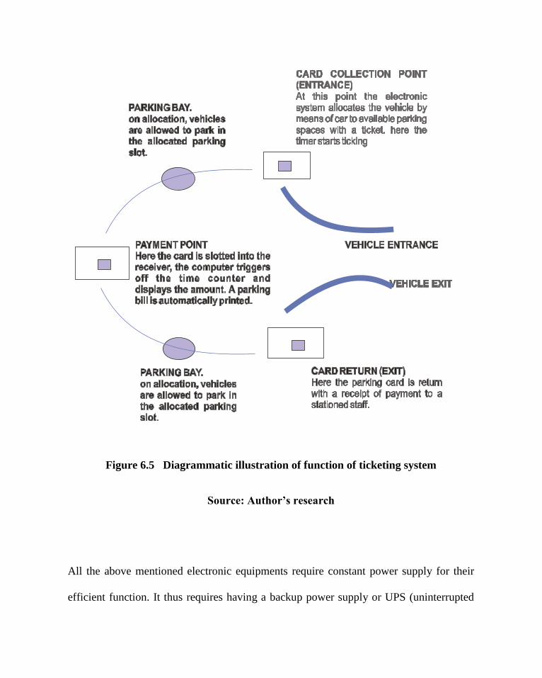
Figure 6.5 Diagrammatic illustration of function of ticketing system
Source: Author’s research
All the above mentioned electronic equipments require constant power supply for their
efficient function. It thus requires having a backup power supply or UPS (uninterrupted

power supply) that would be able to last at least 30minutes. This would help to cover the
periods between switching of power supply from the mains to standby generators and
also help to cater for short periods of technical discrepancies in the power supply.
6.6 PLANNING REGULATIONS
The following planning laws are those relevant for commercial developments from the
Lagos Island Urban and Physical planning department.
The set back for commercial areas are as follows
From front 6m
From sides 6m
From back 3m
For buildings with ground floor area of 1000m2 could go up to heights of 4-5
floors.
Buildings with ground floor area of above 2000m2 could go up to heights of 10
floors.
The ground floor area for all storey buildings should be open for parking.
The set back for any development from the lagoon is 50m

CHAPTER SEVEN
7.0 DESIGN APPROACH
The architecture of any building structure is a complex embodiment of the various
conclusions of different thought process. As such, it is easier to deal with these thought
processes individually and then synthesize them into an overall design. The issue to be
dealt with is single for this design are as follows below.
7.1 SITE SPACE USAGE
Since the aim of the design is space management to free up the amount of land used up as
parking, it would therefore be necessary to know which part of the site is to be utilised for
the purpose of the design and which is to be freed up.
The figure below shows the total amount of space that has been allocated to solve the
parking problems along the Marina Street. The scope of this design shall utilise the space
marked out in the figure below between bordered by Oando petrol station to the West and
the CMS road to the East.

Figure 7.1: Total site area
Source: Lagos Island Local Government

Figure 7.2: Total site area
Source: Lagos Island Local Government
7.2 ZONING

The peculiarity of this design is that it is to cater for humans and most especially
automobile. Consequently, the zoning considerations are in a different perspective. The
site functions are divided into three:
(a) The multi storey car park
(b) Public areas
(c) Ancillary facilities
The zones would be arranged such that the multi-storey car a park is situated at the rear
end of the building. The public area would have the main pedestrian access and would be
situated at the front close to the ancillary facility area of the building to ease accessibility
by pedestrians.

multi-storey car park area
Vehicular access through ramps
pedestrian access
pedestrian access
circulation lobbycirculation lobby
ancillary facilityancillary facility
circulation lobby
Vehicular access through ramps
Vehicular access through ramps
Figure 7.3: Zonal Relationship
Source: Author’s Research

7.3 SPATIAL RELATIONSHIP
The spaces are going to be related in their respective zones as shown in the bubble
diagram below. The spatial relationship would be to enhance the circulation of the
pedestrians within and around the building. The most related spaces are to be closely
linked.
The traffic flow is such that is enhances security of pedestrians within the building.

MULTI-STOREY CAR
PARK
SNACK’S BAR
OFFICES
CAFÉ
RESTAURANT
AUTO MECHANIC
CAR WASH
LETTABLE SHOPS
Figure 7.4: Ancillary facility Bubble diagram
Source: Author’s Research

LONG STAY
ENT.
LONG STAY
LONG STAYLONG STAY
TICKET POINT
SHORT STAY SHORT STAYSTAIRS
EXIT
ANCILLARY FACILITY
ENT.
EXIT
ANCILLARY FACILITY
STAIRS
TICKET POINT
Figure 7.5: Multi storey car park bubble diagram
Source: Author’s Research
7.4 DESIGN PHILOSOPHY
In the process of evolving a design, an approach is taken which must employ a system of
thoughts or underlying set of principles. The utmost purpose of a building is to serve a
function. In addition to function, buildings are designed to create an impression,

expressed through forms. No wonder it is said that every architectural object has a
communicative power. Through symbolism, buildings express their function to the
onlooker. This is important in the design of a multi-storey car park complex since the
building is meant to advertise itself.
While giving the building a communicative ability, the designer applies the programmatic
concept in which he responds to the pragmatic requirements of the multi-storey car park
complex.
7.5 DESIGN CONCEPT
The concept of this design is:
“To enhance smooth circulation of automobile from the access road; (off traffic)
into and out of the complex, back unto the access road in a manner reminiscent of
the ant’s escape when the ant hill is attacked. The ants move out from a core and
move down in different direction; the ant finding its escape through every
possible exit unto level ground again.”
The formulation of this concept is based on the need for ceaseless traffic into the building
and bearing in mind that there are daily rush hours especially after work when there
needs to be a mass exit possibility. The evolution of this concept can be expressed in
sketch as shown.

Figure 7.6: Conceptual formulation
Source: Author’s Research
7.5.1 Evolution of Elevation Form
The form of the elevation is also derived from the functional concept of the design. The
elevation is to be a form in abstraction of the original ‘ants escaping from an ant hill’ idea
in two places.
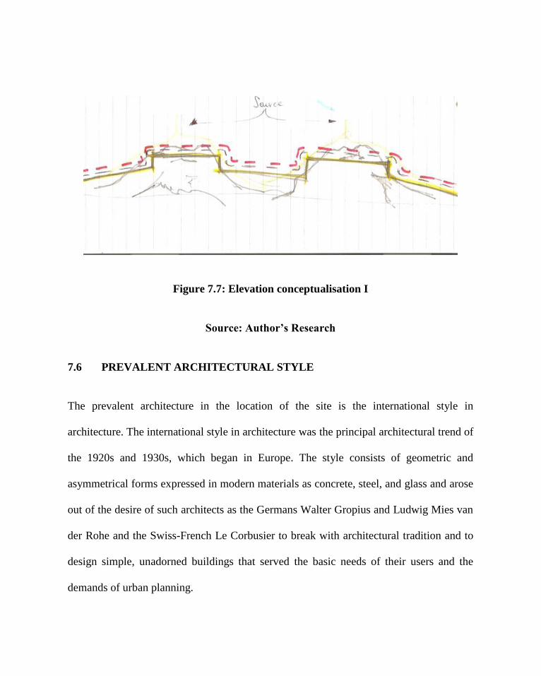
Figure 7.7: Elevation conceptualisation I
Source: Author’s Research
7.6 PREVALENT ARCHITECTURAL STYLE
The prevalent architecture in the location of the site is the international style in
architecture. The international style in architecture was the principal architectural trend of
the 1920s and 1930s, which began in Europe. The style consists of geometric and
asymmetrical forms expressed in modern materials as concrete, steel, and glass and arose
out of the desire of such architects as the Germans Walter Gropius and Ludwig Mies van
der Rohe and the Swiss-French Le Corbusier to break with architectural tradition and to
design simple, unadorned buildings that served the basic needs of their users and the
demands of urban planning.

All buildings along the Marina Street are high rise structures in the international style
with the use of concrete and glass being predominant.
In designing any building form within the vicinity of this project, it is very necessary to
consider styles that would be perfectly integrated into the surrounding in the use of
materials and form.
7.7 STRUCTURE AND GRID PATTERN
A multi storey car park requires a lot of structural details as it is supposed to withstand
very heavy loads during its lifetime without failing.
A careful consideration of various factors leads to the use of a grid of 10.2m * 7.2m. This
grid was arrived at due to the consideration of space between columns and the
accommodation capacity. Using 7.2m from column to column would enable three cars
park conveniently between columns. The grid dimensions were also considered on the
bases of the material use. The material to be used is concrete. Concrete can handle this
dimension structurally only with the use of special floors supported on massive columns
which have already been given allowance for in the grid choice.
7.8 FLOORING
The need to have large span of floors supporting heavy loads develops the need for
special floors. A careful consideration of the various floors leads to the use of double

beam floors. Double beam floors usually have main beams distributing load from beam to
beam and the auxiliary beams which run from beam-end to beam-end of the main beams
to transfer load from the mid-span of the floor to the main beams and onto the columns.
Figure 7.8 Double beam floor
Source: Ching (2001)
7.9 CONSTRUCTION TECHNIQUES AND COST
Construction of a massive building as this is very challenging and expensive. Because of
these, the building is to be designed in modules. The module system is such that every
unit of a module has similar facilities and its own exit points. This enables a phases-by-
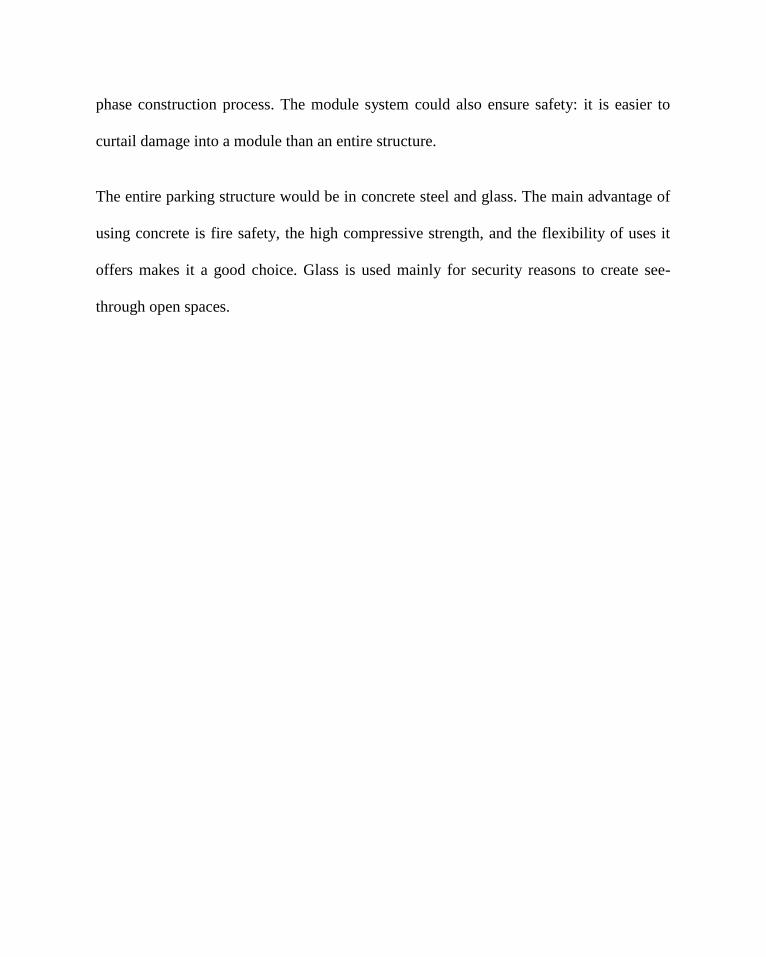
phase construction process. The module system could also ensure safety: it is easier to
curtail damage into a module than an entire structure.
The entire parking structure would be in concrete steel and glass. The main advantage of
using concrete is fire safety, the high compressive strength, and the flexibility of uses it
offers makes it a good choice. Glass is used mainly for security reasons to create see-
through open spaces.

CONCLUSION
The Multi Storey car park complex for Marina, Lagos is a project which has been
embarked upon as an academic exercise but not withstanding its potential for full
execution. As a result, in-depth analysis and study of the project is very essential in order
to get a good grasp of the design and what it entails as well as what is involved.
The study of the existing situation, analysis of the case study, other materials and
professionals brought the realisation of the design. The design is going to successfully
house the mass of cars parked on open ground surfaces along the Marina Street, allowing
for more free open spaces. For the research, it can be seen that multi storey car parks are
so important to urban areas that various governments in foreign countries are beginning
to place legislation on them in the form of standards and requirements they must meet.
It is recommended that in managing the spaces left of our urban areas, a solution to the
parking menace has to be proffered. A way out of this is through the use of multi storey
car parks and parking legislations which will be functional and add to the aesthetics of
the environment.
In conclusion, recognising the peculiarity of Lagos in terms of shortage of land for
expansion purposes and the congestion in terms of housing, shops, markets, and other
land uses competing for limited land space, it is necessary to accept that automobiles
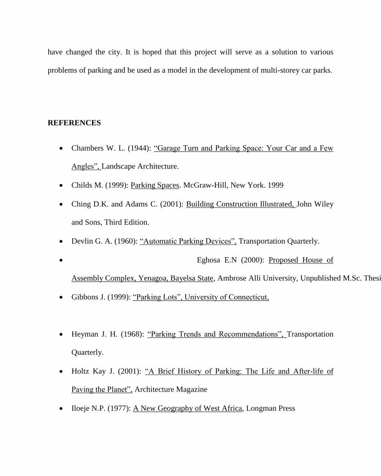
have changed the city. It is hoped that this project will serve as a solution to various
problems of parking and be used as a model in the development of multi-storey car parks.
REFERENCES
Chambers W. L. (1944): “Garage Turn and Parking Space: Your Car and a Few
Angles”, Landscape Architecture.
Childs M. (1999): Parking Spaces. McGraw-Hill, New York. 1999
Ching D.K. and Adams C. (2001): Building Construction Illustrated, John Wiley
and Sons, Third Edition.
Devlin G. A. (1960): “Automatic Parking Devices”, Transportation Quarterly.
Eghosa E.N (2000): Proposed House of
Assembly Complex, Yenagoa, Bayelsa State, Ambrose Alli University, Unpublished M.Sc. Thesis
Gibbons J. (1999): “Parking Lots”, University of Connecticut,
Heyman J. H. (1968): “Parking Trends and Recommendations”, Transportation
Quarterly.
Holtz Kay J. (2001): “A Brief History of Parking: The Life and After-life of
Paving the Planet”, Architecture Magazine
Iloeje N.P. (1977): A New Geography of West Africa, Longman Press
Jackle J.A. and Sculle K. A. (2004): Lots of parking: Land use in a car culture
University of Virginia press.
Kanaan G. and Witheford D. K. (1973): “Parking Lot Design Standards”,
Transportation Quarterly.
Koenig R. O. (1937): “The Economics of the Parking Lot”, The Planners’ Journal.
Kressel S. (2000): “Suburbanization from Within: Are We Retrofitting Our Cities
For Parking Lots?”, Transportation Quarterly.
Langdon P. (2005): “Pave paradise? No, ditch the parking lot”, New Urban News.
Mayer M. R. (2005): Parking Lots: An Investigation of Public Space in the
contemporary American city. Georgia Institute of Technology, Unpublished
M.Sc. Thesis.
McDonald S. S. (2007): “Parking Facilities”, National Institute of Building.
McQuade W. (1960): “Where are the parked cars?”, Architectural Forum
Neufert E & P (2000): Architects’ Data, Blackwell Publishing.
Perkins L.R.R. (1997) “Why Reduce Automobile Dependence”, Livable Cities
Rock M. (1992): “The Automobile and the Environment”, Chelsea House
Publishers
Shoup D. (1997): “The High Cost of Free Parking”, Journal of Planning
Education and Research.
INTERNET

Advameg Inc (2007): “Lagos history”, http://www.city-data.com/world-
cities/Lagos.html
“Bosch multi-storey car park” http://www.messe-stuttgart.de/cms/messegelaende-
parkhaus.0.html?&L=1
Brown J. (2002): Gateshead Car Park, http://mysite.wanadoo-
members.co.uk/owenluder/page5.html
Haag G. (1997): “Robotic Parking - Automated Parking”
http://www.roboticparking.com/productline.html
Omowa, J. (2007). Nigeria: Lagos and the Megacity Dream. all africa.com
retrieved June 30, 2008, from www.allAfrica_com Nigeria Lagos and the
Megacity Dream (Page 1 of 1).html
Automobile. (2007). Microsoft Encarta 2007. Microsoft Corporation.
Parking lot. (2008). Wikipedia encyclopedia. www.wikipedia_com/parking
lot.html
“History of Lagos”,
http://www.lagosstate.gov.ng/c/portal/layout?p_l_id=PUB.1095
Keilthy L. (2002): “Car Park Engineering Design -
Working Together for 'Win-Win' Solutions”,
http://www.parkrite.ie/design2.htm
Litman T. (2006): “Parking Management: Strategies, Evaluation and Planning”, V
Victoria Transport Policy Institute, http://www.vtpi.org/

Litman T. (2006): “Parking Management: Innovative Solutions to Vehicle
Parking Problems”, Planetzen www.planetizen.com/node/19149.
Melosi, M. V. (2007): “The Automobile Shapes The City”, Automobile in
American Life and Society,
http://www.autolife.umd.umich.edu/Environment/E_Casestudy/E_casestudy.htm
Multi-Storey car parks,
http://www.gateshead.gov.uk/Transport%20and%20Streets/Parking/carparks/Car
parks.aspx
http://dspace.dial.pipex.com/town/pipexdsl/o/aouq09/getcarter/list.htm
http://Newcastlephotos.blogspot.com/2007/04/trinity-center-multi-storey-car-
park.html
http://www.asphaltnation.com/Articles/index.html
http://www.concast.ie
http://www.patentstorm.us/patents/5893696-description.html
www.schreiberstahlbau.de
OTHERS
Microsoft Encarta (1997): “International Style”, Microsoft Corporation.
Sport England (1999), “Car Park and Landscape Design”
NARPAC Inc (2007): “The Missing Link in Public Transit: Public Parking”

SITE PLAN
GROUND FLOOR PLAN
TYPICAL 1ST
, 2ND
AND 3RD FLOOR PLAN
ROOF PLAN
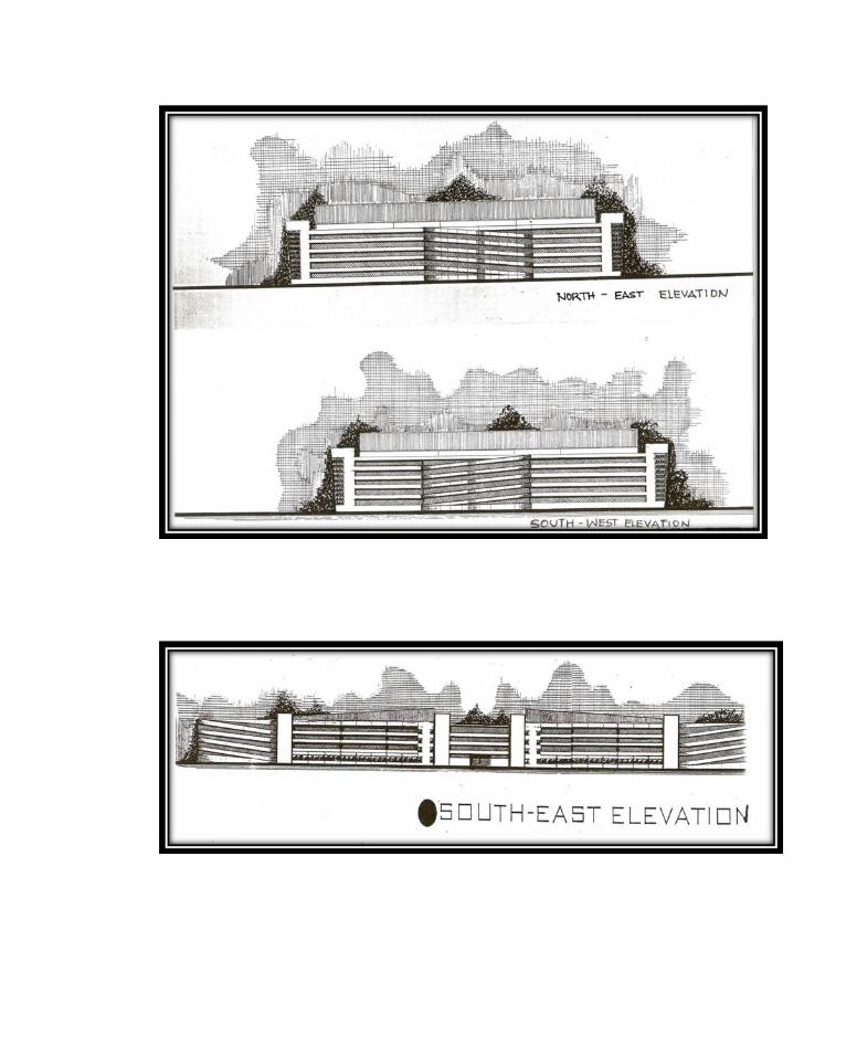

TYPICAL FLOOR PLAN SHOWING ESCAPE ROUTES, WATER
SPRINKLERS AND POSSIBLE CAMERA POSITION.

PERSPECTIVE VIEW