multi-terrain earth landing systems applicable for manned ... · multi-terrain earth landing...
TRANSCRIPT

Multi-Terrain Earth Landing SystemsApplicable for Manned Space Capsules
Edwin L. FasanellaNASA Langley Research CenterEdwin. [email protected]
Abstract
A key element of the President's Vision for Space Exploration is the development of anew space transportation system to replace Shuttle that will enable manned exploration ofthe moon, Mars, and beyond. NASA has tasked the Constellation Program with thedevelopment of this architecture, which includes the Ares launch vehicle and Orionmanned spacecraft. The Orion spacecraft must carry six astronauts and its primarystructure should be reusable, if practical. These requirements led the ConstellationProgram to consider a baseline land landing on return to earth. To assess the landingsystem options for Orion, a review of current operational parachute landing systems suchas those used for the F-111 escape module and the Soyuz is performed. In particular,landing systems with airbags and retrorockets that would enable reusability of the Orioncapsule are investigated. In addition, Apollo tests and analyses conducted in the 1960'sfor both water and land landings are reviewed. Finally, tests and dynamic finite elementsimulations to understand land landings for the Orion spacecraft are also presented.
Introduction
After retiring the Space Shuttle in 2010, NASA plans to replace the Space Shuttle orbiterwith the Orion spacecraft, a capsule that is larger than the Apollo command module withroom for up to six astronauts. Orion will be boosted into orbit by an Ares 1 rocket thatwill use the Space Shuttle Solid Rocket Booster (SRB). The Orion capsule will servicethe International Space Station (ISS), and later versions are planned to travel to the moonand then on to Mars. On return from space, the Orion capsule will descend to earthsuspended from a parachute. Weight constraints are steering the current Orion designtowards water landings, but the design goal is for the Orion crew to "walk away" fromland landings due to a pad abort or for any other nominal land landing. Landing siteterrain is highly variable, with very hard soil at sites such as the dry-lake beds inCalifornia near NASA Dryden and very soft soil at sites such as Carson Sink, Nevada.For a pad or ascent abort from NASA Kennedy Space Center, water is the preferredimpact surface, but if the capsule blows back onto land, the impact surface can vary fromextremely soft dry sand to hard prepared surfaces. Consequently, landing systems forOrion must be designed for multi-terrain impacts.
For a survivable landing, the velocity of a manned vehicle returning from space must bereduced from approximately 18,000 mph for an earth orbit to a landing sink rate of just afew feet per second. This deceleration can be accomplished using a combination ofseveral different technologies, which may include parachutes, airbags, crushable
1
https://ntrs.nasa.gov/search.jsp?R=20090026491 2018-07-10T04:44:02+00:00Z

strictures and retrorockets. Parachutes were used on Apollo and Soyuz, while airbagshave been used on Mars missions, the F-111 fighter jet, and some helicopters. Soyuz alsoused retrorockets. This paper will present a survey of all of these previously flownlanding system technologies and will extract lessons applicable for Orion.
In terms of new landing system work, from 2005 — 2007 NASA's Orion Landing System(LS) Advanced Development Program (ADP) investigated several energy absorbingsystems for land landing, including base-mounted retrorocket systems (St.Vaughan,2007). Concurrently, the ADP began swing testing of full-scale airbag systems on Orionboilerplate test articles at the NASA Langley Landing and Impact Research (LandIR)facility. The airbags are in pairs with a vented main bag for energy absorption and aninner anti-bottoming airbag to prevent ground contact. Although airbag systems withanti-bottoming airbags are somewhat heavier than retrorocket landing systems, airbagsystems can both prevent the structure from contacting the impact surface and reduce theimpact loads during a land landing. This paper will present representative test datagenerated at LandIR of developmental airbag landing systems for the Orion capsule.Simulations of airbag systems onto soft soil and of space capsules into water using thenonlinear dynamic finite element code LS-DYNA (Hallquist, 2006) will also bepresented and discussed. The goal of landing system research is to develop concepts toattenuate impact loads transmitted to the crew to noninjurious levels. Consequently,human tolerance to impact will be discussed in the next section.
Human Tolerance to Impact
In order to design a viable Orion landing system, the limits on occupant accelerationsmust be understood. The accelerations on the seat and occupant in an impact aremeasured in local X, Y, and Z-directions. For an upright seated occupant such as apassenger in a car, the X-axis is horizontal, Z is positive upward, and Y is to the side.Since astronauts are lying on their backs in a supine position, the rearward impact forcefor a flat capsule impact is in the X-direction perpendicular to the spine and is distributedover a large area. To specify the occupant local axis system in terms of the occupant'sbody, the +X-direction is also called an "eyeballs-in" direction. The "eyeballs" move inthe direction opposite to the acceleration vector similar to a bubble in an acceleratedliquid. Colonel John Stapp, a pioneer who rode rocket sleds to detennine humantolerance, sustained peak accelerations over 46 G's for frontal accelerations (-X-direction, eyeballs out) in the early 1950's without sustaining permanent injuries.Colonel Stapp was in an upright seated position. Obviously, an occupant must be wellrestrained to survive such an impact. For acceleration along the spine, the tolerance ismuch lower. For example, an acceleration of 20 G's for 0.1 second is the levelexperienced by crew in ejection seats. From operational experience and human tolerancestudies, it is known that any sustained acceleration of 20 G's or more along the spine canproduce serious injuries including cracked vertebra (Eiband, 1959).
Various models of the seated occupant have been developed including the DynamicResponse Index (DRI), commonly called the Brinkley index after its developer (Brinkleyand Moser, 1989). Brinkley lowered the dynamic response limits for NASA to include
2

-T NUMBER OF NONFATALEJECTIONS
64
62
65
89
33
48
)ENOTES ROCKET CATAPULT
50
40
30
-g
H 10
s
'z zJ 1
Z 0.5aN 0.2
debilitated astronauts (very low). The limits used by the Constellation program for Orionnominal and off nominal landings are shown in Table 1, while the limits from Brinkleyand Moser (1989) are given in Table 2. Note that the dynamic response (DR) levels (low,moderate, and high risk) correspond to an injury risk of about 0.5%, 5%, and 50%,respectively. Operational spinal injury rate for ejections from various military aircraftversus the computed DRI is shown in Figure 1.
X Y ZDR level (eyeball - out, in) (eyeballs right, left) ((eyeballs u , down
DR,, < 0 DR, > 0 DR,. < 0 DR,. > 0 DR- < 0 DR- > 0Very low(nominal)
-22.4 31 -11.8 11.8 -11 13.1
Low(off-nominal) -28 35 -14 14 -13.4 15.2
Table 1. Orion Dynamic Response Limits
DR levelX
(eyeballs out, in)Y
(eyeballs right, left)Z
(eyeballs up, down)DR,. < 0 DR,. > 0 DR,. < 0 DR,. > 0 DR- < 0 DR- > 0
Low (same asNASA spec)
-28 35 -14 14 -13.4 15.2
Moderate -35 40 -17 17 -16.5 18High Risk -46 46 -22 22 -20.4 22.4
Note that if side restraints are used, the DR levels for Y increase to -15 and +15 (Low), -20 and +20 (Moderate) and -30 and +30 (High Risk).
Table 2. Dynamic Response Limits From Brinkley, 1989.
CALCULATED FROMCAnAVER 11ATA
10 la 14 18 Is 20 22 24
DYNAMIC RESPONSE INDEX
Figure 1. Spinal injury rate for operational ejections from military fighters.
3
Impact tolerance studies for aerospace applications generally use modified automotiveanthropomorphic dummies with an added lumbar load cell above the pelvis to physicallymeasure the dynamic load time-history along the spine under impact conditions. Anyload exceeding 1500 pounds is likely to produce spinal injuries in a 50th-percentile male.
Parachute Systems
The most common initial deceleration systems for spacecraft returning to earth fromspace are parachutes. Aircraft-like landing systems are the safest, but require longrunways and skilled pilots, and the wings and wheels constitute about 20 percent of thevehicle weight. A parachute landing system is generally much lighter than wing systemsat 3 - 6 percent of the vehicle weight, but is limited to weights less than 40,000 pounds(Sarigul-Klijn, 2003). For reliability, either backup chutes or multiple chutes are needed.For example, Mears (1993) reported that the parachute failure rate for non-heavypayloads was 0.4% or 4 out of 1000. Although the Mercury, Gemini, and Apolloprograms had some close calls with water impact landings, notably the sinking of GusGrissom's Liberty Bell 7 Mercury capsule due to a faulty explosive hatch and the oneparachute out water impact of Apollo 15 (West, 1973), there were no injuries or fatalities.Unfortunately, the space shuttle orbiter (Columbia) and the land landing Soyuz capsulehave both had fatal earth entries while attempting land landings from space.
To keep the size of parachute systems reasonable, and to optimize the weight of thelanding system, the terminal velocity of most parachute recovery systems isapproximately 25 to 40 ft/s. In addition to the terminal vertical velocity, the parachuteand capsule move horizontally depending on the wind speed. Capsule landing velocitieswith parachute are close to typical survivable crash impact velocities for small aircraftand helicopters; therefore, one can expect that without some type of mitigation for impactloads onto land, capsules with parachutes alone are likely to produce crew injuries onland landing. The Apollo capsule was designed to impact the water with a hang angle(pitch) of 27 degrees. Since the Apollo entered the water pitched at an angle (thus givingit a rounded wedge shape), the capsule acceleration was nominally 10 G's or less for a 30ft/s impact (Jones, 1970). The Apollo spacecraft also had crushable ribs, and the crewseats were attached to an internal pallet with stroking energy absorbers to alleviate off-nominal impacts. However, either a land landing of Apollo in an abort condition or a flat0-degree attitude water impact with one chute out may have resulted in occupant injuries.Since the probability of a pad abort with a land impact was considered to be low, theApollo program accepted those risks.
With the exception of Soyuz and Apollo, there are few manned recovery systems withparachutes that can be used to assess reliability, cost, or effectiveness. Recently Cirrus, amanufacturer of small fixed wing airplanes, developed a solid-rocket-activated parachutethat could be deployed in just a few seconds by the pilot in case of an emergency. Cirrususes a 55-ft diameter single parachute to gently glide down to earth with the entireaircraft underneath. Several successful deployments have occurred since the system wasmade operational in 2000.
4

Operational Airbag Landing Systems
Large external airbags are being considered for the Orion land landing system to reducethe landing loads and to protect the Orion capsule from damage since one of the designconsiderations of the Constellation Program is reusability, if practical. Internalautomotive airbags are deployed in milliseconds and typically use a hot gas generatorsystem for deployment. In contrast, deployment time for external airbag landing systemsis less stringent and can often be tailored as part of the overall system design. The OrionLS ADP was responsible for test and analysis of prototype airbag (and retrorocket)landing systems suitable for Orion. Consequently, these and other airbag energyattenuating systems will be reviewed in the following subsections of this paper.
:Wars Airbag SystemsThe Mars Exploration Rover (MER) missions with rover payloads "Spirit" and"Opportunity" used Vectran airbags that were the same as those used in the 1997Pathfinder mission. These airbags were inflated over several seconds using a gasgenerator system. The MER airbag system consisted of multi-layer spherical airbagsattached together and to the MER with Criss-crossed straps called tendons that resembleda loose net. Vectran is an excellent choice for the airbag fabric since it is more than twiceas strong as Kevlar, performs better at cold temperatures, and is designed to surviveimpacts with rocks without tearing through all the layers. Extensive testing of the airbagswas performed at NASA Glenn Research Center onto a simulated Mars rocky surface atthe expected Mars impact velocity of approximately 60 ft/s. A photograph of a system ofinterconnected spherical airbags set-up for testing is shown in Figure 2. Since theatmosphere of Mars is very thin, a parachute was not sufficient to slow the MERsufficiently for a safe landing even with the airbags. Thus, retrorockets were activated bya ground-sensing device approximately 50 feet above the Martian surface. The vendorthat supplied the MER airbags also supplied generation 1 and 2 airbags for the NASALangley ADP Orion test program.
Figure 2. Airbag testing for the MER Program.
5

F-111 Module AirbagThe first operational aircraft escape system that used a combination of parachutes andairbags for manned landings onto multi-terrain (land or water) was the 3,000 pound crewescape module of the F-111 fighter (Brinkley, 1968). Although the F-111 module is nota space capsule, the technology, hardware, and impact velocities are applicable. Thevertical impact velocity of the F-111 module with parachute was approximately the sameas is estimated for Orion; i.e., 26 ft/s. Note that unlike a space capsule, the F-111occupants in the module are seated upright and not on their backs. The F-111 airbagsystem consisted of a neoprene-coated nylon cloth airbag that weighed almost 3% of thecapsule's weight. Compressed air tanks were used to inflate the airbag. The airbag waslocated on the flat, underside of the capsule and contained blow-out plugs that weredesigned to tailor the amount of energy absorbed. Beginning in the 1980's andcontinuing through the mid-1990's, impact tests of the F-111 crew escape module ontosoil were performed at the LandIR facility in support of the U.S. Air Force (Chambers,2000). During the 15-year period of time, approximately 70 impact tests were performedof the F-111 crew module with different airbag designs. Some of the tests wereconducted onto concrete and some onto a soil surface under a variety of roll, pitch, andyaw angles to represent the range of impact attitudes possible with a parachute landing.
In 1991, twelve F-111 module impact tests were conducted at LaRC. In those tests, thevertical velocity was varied from 23 to 32 ft/s, while the horizontal velocity was variedfrom 0 to 44.5 ft/s. The accelerations on the pilot and copilot seat pan were measured inthe local X, Y, and Z-directions, where X for a flat impact is horizontal, Z is positiveupward, and Y is to the side. The acceleration to the pilot seat in the Z-direction (eyeballsdown) was 15 G's. For combined vertical and longitudinal velocities, the peakaccelerations in the Z-direction were typically larger than the X- and Y-axis accelerationsand were approximately 20 to 30 G's. In addition to the undesirable accelerations, the F-111 parachute with airbag system was prone to produce excessive rebound velocity withundesirable tumbling as illustrated in Figure 3. For Orion, similar accelerations with thecrew on its back would be more tolerable than in the F-1 I1 with the crew seated upright.Although the F-111 airbag was modified many times, its effectiveness was marginal inreducing the impact forces to the crew inside the capsule during land landings. The F-111 was retired in 1996, shortly after the last series of airbag testing was completed.Although many resources were spent on the F-111 impact attenuation system, the designwas never frilly satisfactory as the operational spinal injury rate at over 20 % was higherthan other comparable systems that used ejection seats.
6

f
Th
7 -T-s
Figure 3. Photographs of an impact test of the F-111 crew escape module with airbagattenuation system.
Helicopter External Airbag SystemsStarting in the 1990's, Rafael, a company headquartered in Israel, has been developingmultiple automotive-type (explosive gas-generating) airbags beneath helicopters to limitacceleration to the occupants and to limit damage to the helicopter for survivable crashes(Yosuf, et al, 2006). The US Navy has sponsored some of this development. TheRotorcraft External Airbag Protection System (REAPS) airbags are attached under thefuselage of the rotorcraft, and are designed to moderate the crash impact loads whenimpact either hard soil or water. A proximity sensor used to monitor the distance abovethe impact surface has been one of the primary problems in developing this technology.Also of concern is the ability of automotive type airbags to handle the shear loadsgenerated during landings with high horizontal velocities.
In December 2005, REAPS testing took place near Phoenix, AZ using a Bell 206rotorcraft as the test article. Two drops at impact velocities of 27- and 34-ft/s wereconducted at a maximum gross weight of 3300 lbs. The rotorcraft was equipped with fourAnthropomorphic Test Devices (ATD's); two were 50th-percentile male dummies, onewas a 95th-percentile male dummy, and one was a 5th-percentile female dummy.According to the press release, the passengers were subjected to an impact of less than25G with "absolutely no rebound and secondary impact." If the sensor and activationproblems can be solved, the system shows promise for commercial helicopter use.
Recently, Boeing reported on an external airbag system to protect UAV's in the event ofa crash (Bolukbasi, 2007). In the airbag development program, four airbags wereattached to the skid gear of a MD 530 helicopter, which was used as the test-bed. It wasdetermined that automotive type airbags were not suitable for the application due to theoperating environment. Consequently, polyurethane coated Kevlar fabric was used.
Operational Retrorocket Landing Systems
Retrorockets have been used by the Russians from the beginning of their space programfor land landings. Retrorockets on the RSC Energia Soyuz and the Chinese variantShenzhou have proven to be weight efficient and highly reliable. Apollo-era testing
7
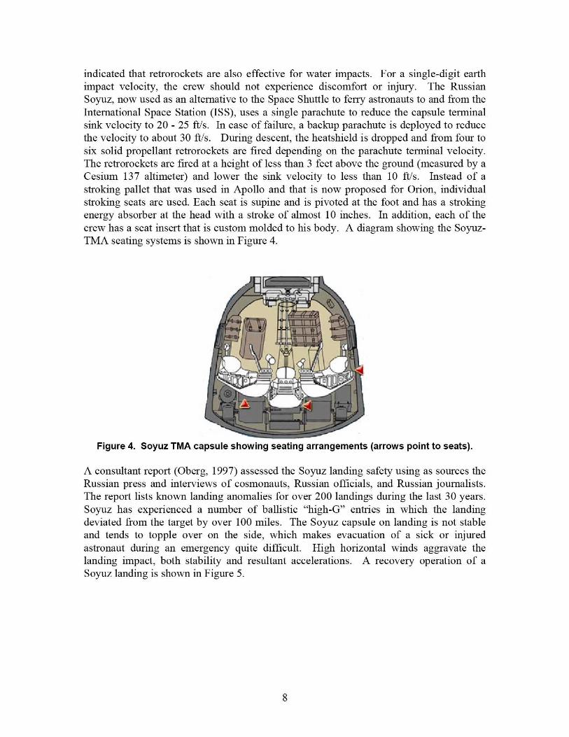
indicated that retrorockets are also effective for water impacts. For a single-digit earthimpact velocity, the crew should not experience discomfort or injury. The RussianSoyuz, now used as an alternative to the Space Shuttle to ferry astronauts to and from theInternational Space Station (ISS), uses a single parachute to reduce the capsule terminalsink velocity to 20 - 25 ft/s. In case of failure, a backup parachute is deployed to reducethe velocity to about 30 ft/s. During descent, the heatshield is dropped and from four tosix solid propellant retrorockets are fired depending on the parachute terminal velocity.The retrorockets are fired at a height of less than 3 feet above the ground (measured by aCesium 137 altimeter) and lower the sink velocity to less than 10 ft/s. Instead of astroking pallet that was used in Apollo and that is now proposed for Orion, individualstroking seats are used. Each seat is supine and is pivoted at the foot and has a strokingenergy absorber at the head with a stroke of almost 10 inches. In addition, each of thecrew has a seat insert that is custom molded to his body. A diagram showing the Soyuz-TMA seating systems is shown in Figure 4.
Figure 4. Soyuz TMA capsule showing seating arrangements (arrows point to seats).
A consultant report (Oberg, 1997) assessed the Soyuz landing safety using as sources theRussian press and interviews of cosmonauts, Russian officials, and Russian journalists.The report lists known landing anomalies for over 200 landings during the last 30 years.Soyuz has experienced a number of ballistic "high-G" entries in which the landingdeviated from the target by over 100 miles. The Soyuz capsule on landing is not stableand tends to topple over on the side, which makes evacuation of a sick or injuredastronaut during an emergency quite difficult. High horizontal winds aggravate thelanding impact, both stability and resultant accelerations. A recovery operation of aSoyuz landing is shown in Figure 5.
8

Figure 5. Recovery of a Soyuz capsule. Note the capsule is on its side.
Other non-man-rated parachute delivery systems, such as those used by the military todeliver cargo, incorporate a confluence-mounted retrorocket. With this system, theretrorocket is deployed with the parachute and is suspended below the parachute abovethe capsule (See Fi gure 6). Such a system was considered for the Constellation ProgramOrion capsule by the prime contractor, but was rejected due to reliability concernsregarding entanglement of the retrorocket during parachute deployment.
Figure 6. Confluence retrorocket system showing rocket blast just before impact.
9

Apollo Experience
Apollo data were investigated to assess options, relative costs, and benefits for the designof a safe Orion landing system. Orion is larger than Apollo, but the shape can be scaledgeometrically. Although the structure of Orion will be quite different, the many tests andanalyses performed for Apollo landings are well worth re-examining. Thus, this reportwill summarize the tests and analyses that were conducted by the Apollo designers for theCommand Module (CM) landings on both water (McGehee, et al, 1959; and Benson,1966) and land (McCullough, et al, 1972). A great deal of work was performed in the1960's, both in full- and sub-scale testing and analysis. The Apollo CM at 11,000-12,000pounds on landing was both lighter and smaller than the current configuration for Orionat 18,000-20,000 pounds. As a first approximation, the accelerations from the Apollotests and analyses can be applied directly to Orion as conservative benchmark data.Pictures of test facilities that were used for water and soil impact testing of full-scaleApollo boilerplates and capsules that closely resembled flight hardware are shown inFigure 7.
(a) North American Aviation (b) Johnson Space Center
Figure 7. Apollo water impact test at North American Aviation and Apollo ground impacttest at what is now Johnson Space Center.
Both test and analysis show a land landing generally produces higher accelerations for agiven impact velocity than water. Soil material properties, unlike water, are highlyvariable with bearing pressures ranging from a few pounds-per-square-inch (psi) tohundreds of psi. Thus, for safe soil landings, either airbags or retrorockets are required toreduce the impact accelerations to less than 10 G's. Using the systems approach outlinedwith a load-limiting seat pallet for off nominal and severe impacts, the accelerationstransmitted to the occupants can be reduced to survivable and hopefully non-injuriouslevels for all but catastrophic failures.
Apollo Land Impact Test ProgramMany of the Apollo reports used scaling in which the acceleration of both the scale modeland the full-size capsule scaled as one. For the acceleration to be scaled as one, the
10

velocity of the scale model must be multiplied by the square root of the scaling factor.Although the Apollo capsule is similar in size to Orion, the dimensions and volumes ofthe Apollo and Orion do not fit the classical scaling laws. However, one canconservatively use Apollo accelerations and apply them to Orion. Scaling laws wouldindicate that the Orion accelerations should be slightly less than Apollo for the sameimpact velocity vector.
Beginning in 1967, a series of Apollo Land Impact tests were conducted at NASAJohnson Space Center (JSC), referred to during Apollo as the Manned Spacecraft Center(MSC), and at NASA Kennedy Space Center (KSC) using both "boiler plate" full-sizetest articles and actual spacecraft capsules. The Apollo capsule did have crushable ribsalong the +Z direction, which is the preferred water impact orientation. These testsprovided a good starting point for an estimate of Orion land impact loads without specialenergy attenuation or retro-rockets. During the Apollo study, 51 "boiler plate" tests wereconducted and six Apollo Command Module tests were performed (McCullough, 1972).Since Apollo was "optimized" for a water impact, the Command Module (CM) hadparachutes attached such that the Z spacecraft axis was pitched down 27.5 degrees (-27.5degrees) with respect to the horizontal velocity. Because the CM could rotate about the"vertical," a roll angle was also specified in the report to define the orientation withrespect to the velocity vector. From Figure 8, note that the CG has a Z-axis offset andthat the crew's feet point in the +Z direction. Thus, a 0-degree roll will be referred to as a"toe-in" impact orientation (see Figure 8). When compared to Apollo, the Orion +Z axisis opposite. If the CM in Figure 8 should roll 180 degrees about the vertical, then theorientation at impact would be called a 180-degree roll or "heel-in" impact.
CENTER OF PARACHUTE X itch = -27.5 deCANOPY SYSTEM p gXG ®i V
"l$ i RISER PLANE: SURFACE GENERATED
YGO' paY RISER CENTERLINE
D AND LOCAL VERTICAL
r 0
D XCM1 T
,
2 G `,
1 '_Z CM vv
Vertical Velocity`'ZCM Horizontal Velocity
YCM
Figure 8. 0-degree roll (toe-in) and -27.5 deg pitch impact of Apollo CM into soil. TheApollo +Z axis points away from the feet while the Orion +Z axis points out of the head.
11
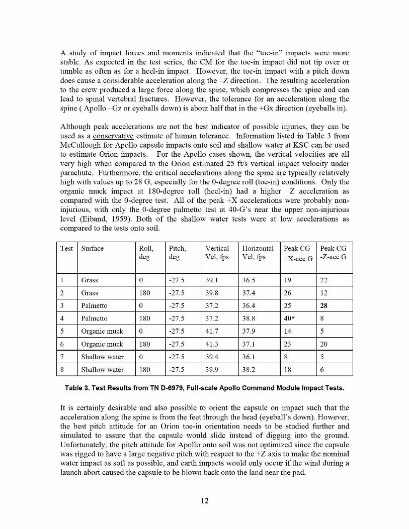
A study of impact forces and moments indicated that the "toe-in" impacts were morestable. As expected in the test series, the CM for the toe-in impact did not tip over ortumble as often as for a heel-in impact. However, the toe-in impact with a pitch downdoes cause a considerable acceleration along the —Z direction. The resulting accelerationto the crew produced a large force along the spine, which compresses the spine and canlead to spinal vertebral fractures. However, the tolerance for an acceleration along thespine ( Apollo —Gz or eyeballs down) is about half that in the +Gx direction (eyeballs in).
Although peak accelerations are not the best indicator of possible injuries, they can beused as a conservative estimate of human tolerance. Information listed in Table 3 fromMcCullough for Apollo capsule impacts onto soil and shallow water at KSC can be usedto estimate Orion impacts. For the Apollo cases shown, the vertical velocities are allvery high when compared to the Orion estimated 25 ft/s vertical impact velocity underparachute. Furthermore, the critical accelerations along the spine are typically relativelyhigh with values up to 28 G, especially for the 0-degree roll (toe-in) conditions. Only theorganic muck impact at 180-degree roll (heel-in) had a higher —Z acceleration ascompared with the 0-degree test. All of the peak +X accelerations were probably non-injurious, with only the 0-degree palmetto test at 40-G's near the upper non-injuriouslevel (Eiband, 1959). Both of the shallow water tests were at low accelerations ascompared to the tests onto soil.
Test Surface Roll,deg
Pitch,deg
VerticalVel, fps
HorizontalVel, fps
Peak CG+X-acc G
Peak CG-Z-acc G
1 Grass 0 -27.5 39.1 36.5 19 22
2 Grass 180 -27.5 39.8 37.4 26 12
3 Palmetto 0 -27.5 37.2 36.4 25 28
4 Palmetto 180 -27.5 37.2 38.8 40* 8
5 Organic muck 0 -27.5 41.7 37.9 14 5
6 Organic muck 180 -27.5 41.3 37.1 23 20
7 Shallow water 0 -27.5 39.4 36.1 8 5
8 Shallow water 180 -27.5 39.9 38.2 18 6
Table 3. Test Results from TN D-6979, Full-scale Apollo Command Module Impact Tests.
It is certainly desirable and also possible to orient the capsule on impact such that theacceleration along the spine is from the feet through the head (eyeball's down). However,the best pitch attitude for an Orion toe-in orientation needs to be studied further andsimulated to assure that the capsule would slide instead of digging into the ground.Unfortunately, the pitch attitude for Apollo onto soil was not optimized since the capsulewas rigged to have a large negative pitch with respect to the +Z axis to make the nominalwater impact as soft as possible, and earth impacts would only occur if the wind during alaunch abort caused the capsule to be blown back onto the land near the pad.
12

3i I 15-i 0-
I 30—© CJ I PAD-
so-X— U°sr°hl°
25 ^ I> ^ IG
xo ^ 1I
D ^
0 f
II
I
a
-5 j C^II D
I1a II
—15 l
II1
30
tv
s
n
4r?
b D
D b
Acce I,G's
Fortunately, some scale model testing was performed for 1/4-scale Apollo capsules ontodry sand in which the pitch attitude and horizontal velocity were varied, but the verticalvelocity was held constant at 30 ft/s (Benson and West, 1965). The 1/4-scale model resultswere scaled up to full scale using Froude scaling laws. Accelerations along the —Zdirection (spine) for pitch angles from -27.5 (defined as toe-in) to +20 (positive definedas heel-in) are shown in Figure 9. The "D" shapes, which are colored light green, weretests for a horizontal velocity of 15 ft/s. As one might expect, a large negative (toe-in)pitch produces a high acceleration along the spine. Since a limit of 10 to 15 G's has beenset along the spine (Z-axis), almost any negative pitch exceeded the limits. The spreadfrom 22-32 G's near -27.5 degrees compares well with the values onto grass (22 G's) andPalmetto (28 G's) reported by McCullough in Table 3. Only the 50 ft/s extremehorizontal velocity produced a peak acceleration above 10 G's for positive heel-in pitch.However, positive heel-in pitch is generally unstable and led to some dramatic tumbling.
H°rI a°nr°I . .I If►lwal
-30° -35° -30° 415° -100 -5° 0° i° 10° 15° 200
Pitch Angle at Impact, degreesFigure 9. Peak accelerations along the Z-axis as a function of capsule pitch for sand
impacts for horizontal velocities up to 50 ft/s. Vertical velocity was constant at 30 ft/s.
13

Apollo Water Landing Test Data and Analysis
The Apollo Command Module was designed for water landings. Accelerations for waterimpact are lower because the stopping distance is much longer than for land landingimpacts. Many studies were performed using both scaled and frill-scale capsules and"boilerplates" comparing test data to analysis (Wilkerson, 1967; and Stubbs, 1967).From test and analyses performed in the 1960's, it was apparent that if the Apollo capsulewas properly pitched for a water landing, the resultant acceleration to the crew could bekept at 10 - 15 G's, or below. The Apollo capsule was rigged onto the parachute riser ata pitch-down attitude of approximately -27 degrees. Figure 10 shows the maximum X-and Z-accelerations for impact tests of 1/4-scale capsules (scaled to dill-scale) conductedat NASA Langley by Stubbs at approximately 30 - 32 ft/s impact velocity into water.The pitch and the horizontal velocity were both varied for this 0-roll (toe-in)configuration. Results for a nominal pitch of -27.5 degrees is shown by the red arrowswith a maximum X-direction acceleration (eyeballs in) less than 10 G's and a maximumZ-acceleration (eyeballs down) less than 5 G's. Solid black symbols were used toindicate those unstable cases at high horizontal velocity where the capsule flipped over inthe water. In water, the heel-in 180-degree roll is more stable than the toe-in 0-roll,which is opposite to land where the 180-degree roll is less stable and leads to tumbling.Also notice that the horizontal velocity has very little effect on the level of the maximumaccelerations for a given pitch.
Maximum Z X Maximum
X- Acceleration, Z-Acceleration,
G's G's
40p 10
630 v^ o+ ^• ^•
O ^ fl 6 ^
Apollo Nominal Pitch 5 ._ e ^, Q20 1 6 ^^_ .
O AQ h d O10 a r
o^, ppti oa
-40 -30 -20 -10 -40 -30 -20 -10
Pitch Angle Pitch Angle
Vertical Velocity - 30 ftis Black symbols Indicate roll-over.Horizontal Velocity
Circles - 0 ftis In contrast to dirt impact, pitch downTriangles - 30 ftls (zero-roll) is less stable than pitch up for1/4 circle - 50 ft/s water Impacts.
Data from NASA M 6-3900
Figure 10. Accelerations for approximately 30 ftts vertical Apollo water impact versuspitch angle. Zero roll, feet pointing in -Z direction.
A summary of test data for simulated Apollo Command Module impact tests into water atnegative pitch angles from 0 to 47 degrees is shown in Figure 11 (Wilkerson, 1967) with
14
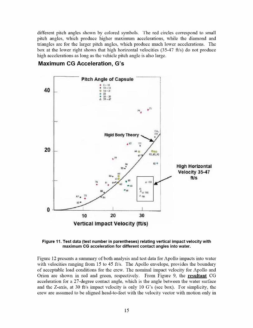
different pitch angles shown by colored symbols. The red circles correspond to smallpitch angles, which produce higher maximum accelerations, while the diamond andtriangles are for the larger pitch angles, which produce much lower accelerations. Thebox at the lower right shows that high horizontal velocities (35-47 ft/s) do not producehigh accelerations as long as the vehicle pitch angle is also large.
Maximum CG Acceleration, G's
Pitch Angle of Capsule
40i x7
a "-.a
MS an
'eAsRigid Body Theory ^. _
•
20
Ke d
aHigh H orizonta lVelocity 35-47
ftis^ ^a Qe+• ^ c wi
e^ * ae bbtFT
r
0 1 I -
110 20 30
Vertica l I mpact Velocity (ftfs)
Figure 11. Test data (test number in parentheses) relating vertical impact velocity withmaximum CG acceleration for different contact angles into water.
Figure 12 presents a summary of both analysis and test data for Apollo impacts into waterwith velocities ranging from 15 to 45 ft/s. The Apollo envelope, provides the boundaryof acceptable load conditions for the crew. The nominal impact velocity for Apollo andOrion are shown in red and green, respectively. From Figure 9, the resultant CGacceleration for a 27-degree contact angle, which is the angle between the water surfaceand the Z-axis, at 30 ft/s impact velocity is only 10 G's (see box). For simplicity, thecrew are assumed to be aligned head-to-feet with the velocity vector with motion only in
15

Ax = AK COs 0
Ar =A, sin 0
V X = V„ COS 9Vz = - V. sin 0
NOMINALApollo Landing
0 - 275 degV M = 30 ttis
Ak 2 10 G'sAx =89 G'sAz = 41 Gs
Z X
feet
b
CEV X and Z-axIs system(Apollo +Z-axis Is -Z-axls CEV)
A401W 4r11NtQ Qen Ql 6t lbcuWuq odaccaplatrta lane tareJalomrr t•^r veycpNQS
/// 3" ih1PGCS BL^u'f,
fwrofi^y,{d+18cLQ ^^arla)
the X-Z plane. In this orientation, the acceleration component in the +X-direction(eyeballs in) is 8.9 G's, while the maximum acceleration is only 4.6 G's in the Z-direction (eyeballs down). These accelerations should be well tolerated. One undesirableaspect of the Apollo water landing was that the capsule was not designed to be activelyrolled to provide an optimum orientation with respect to the crew. One would prefer themaximum Z-acceleration to be eyeballs down, instead of eyeballs up. Obtaining theproper roll orientation at impact is even more important for land landings, especially ifthe retrorockets (or other active attenuation) should fail. Since the Orion is larger andheavier than the Apollo, the data given in Figure 12 can be scaled to find the expectedOrion water impact accelerations. The weight of the Apollo assumed for the curves,shown in Figure 12, was 10,400 pounds. For larger Apollo landing weights, one shouldtake the ratio of 10,400 lbs/actual weight and scale the accelerations shown. Also,Orion's diameter is approximately 1.27 times the diameter of Apollo. For the Apolloaccelerations to apply to the larger Orion, one could multiply the Apollo velocities by thesquare root of the scaling dimension (1.12) to get the equivalent Orion velocity. Or, onecan conservatively use the Apollo accelerations for Orion "as-is" until further testing andanalysis is performed.
704 M1G iP^CG Resultant tta^mf,"t,
Acceleration AR,G's
60 uM1 - asjr:112,21Naeci
soV 35lp: \, I W.7 mlwei
4030 fps
Nominal ApalldVelocity Vr
30
Nominal CEV 25 fp
Velocity V„ <g,`'20 va - a ^o
A. {e.r m^an1Acceleration based onApollo 10,400 lb. weightFor other landing weight, t D v 1s rp.
ta'G n1^a1"'acceleration is tobe scaled by
—_ Curves from+rr anrr to 7 - — ' ^" ^ NASA SP-8046Actuar weight 10 zl1 S] ;D 66
Contact Angle 0 (see diagram)
Figure 12. Resultant CG acceleration as a function of velocity and contact angle for Apollowater impact.
Apollo Land versus IVater Impact
An attempt was made to compare the maximum acceleration components (X- and Z-directions) for Apollo impact tests into water with Apollo impacts onto soil for the same
16

impact conditions. Although Apollo engineers performed hundreds of impact tests, datatime histories were not reported for many of the tests. To perform good comparisons, thetime histories need to be compared. In addition to the maximum acceleration recorded,the durations must be analyzed. Also, the Brinkley dynamic response index, whichprovides a good indication of probability of injury, requires complete acceleration timehistories at the seat location for the X-, Y-, and Z-directions. However, the maximumaccelerations shown in Table 4 do provide some relative indication of severity. Note thatthe Y-axis accelerations are not considered as they were very small in magnitude. FromTable 4, both X- and Z-components of acceleration for impacts into water were small andare colored green. In contrast, all of the accelerations for impacts onto soil at 32 ft/s forboth the X- and Z-directions are above 40 G's. These accelerations along the X-directionmay be barely tolerable; however, the accelerations along the Z-direction at the 40 — 50G's level are almost certain to produce injury. Consequently, these accelerations arecolored red. The time histories for Apollo test 80 into dirt were found in McCullough(1972). These traces were scanned and digitized and input into the Brinkley computermodel to obtain a maximum dynamic response. The limits for the DRI-X (eyeballs in)are 31 for a nominal Orion landing and 35 for off-nominal. The limits for DRI-Z(eyeballs down) are 13.1 for a nominal Orion landing and 15.2 for off-nominal. FromFigure 13, the maximum calculated response for DRI-Z is 15.5, which is above themaximum for an off-nominal landing and would likely produce a moderate probability ofinjury.
Velocity Water Impact Sail Impact
Pitch(down
Horiz
Vert Test MaxAccX
MaxAcc
Z
Test MaxAccX
MaxAccZ
-27.5 0 32 c 80** 40 40
-27.5 0 38 '` 1 9 81 ** 50 50
-27.5 25 32 16** 43 Ar
-27.5 45 32 31*'` 3t: 50
- -l0 0 -23 00' 13- - - 2^-
._' SID a"7-498
TN D-6979 Notes- (1) Very few soil tests under 30 Ns vertical velocity.(21 Very few pitch attitude studies for soil impacts.
TN D-3980 {3) Although 100 1s of tests performed into dirt test matrix is sparse.
Table 4. A Comparison of Apollo Water and Soil Impacts for Similar Impact Conditions.
17
Accel-X, G's (eyeballs in)or DRI
Test 80 Dirt50
40
30
20
10
0
-100 0.01 0.02 0.03 0.04 0.0
Time. sec
DRI—B
z—B - Accel,z
Accel - +Z (eyeballs down)
50
40
30
20
10
0
-10
-0n
sa ivs vertical arop
.................J.1............... ............................ ............................... DRI.-X ..
1
- cce l -x G's
.....................,r^.................................
^ 4f ti
^......... 1 . ...............
... ... ... ... ... .................... .... ... ... ... ... ... .... . .. . .. . .. . .. ... . ....
............................... ........................ ......
1
..........................................1.............1 ......................
rnj
..........................1........................................................
1 `r
f.}
{I+1^,^11^ p U 1^ L ^^ r
_ ... ... .... ... ... ... 1.............. 1{..ti......_........................... 1.
^ 4
Test 80 Dirt
32 M vertical drop
5 0 0.01 0.02 0.03 0.04 0.05
Time, s
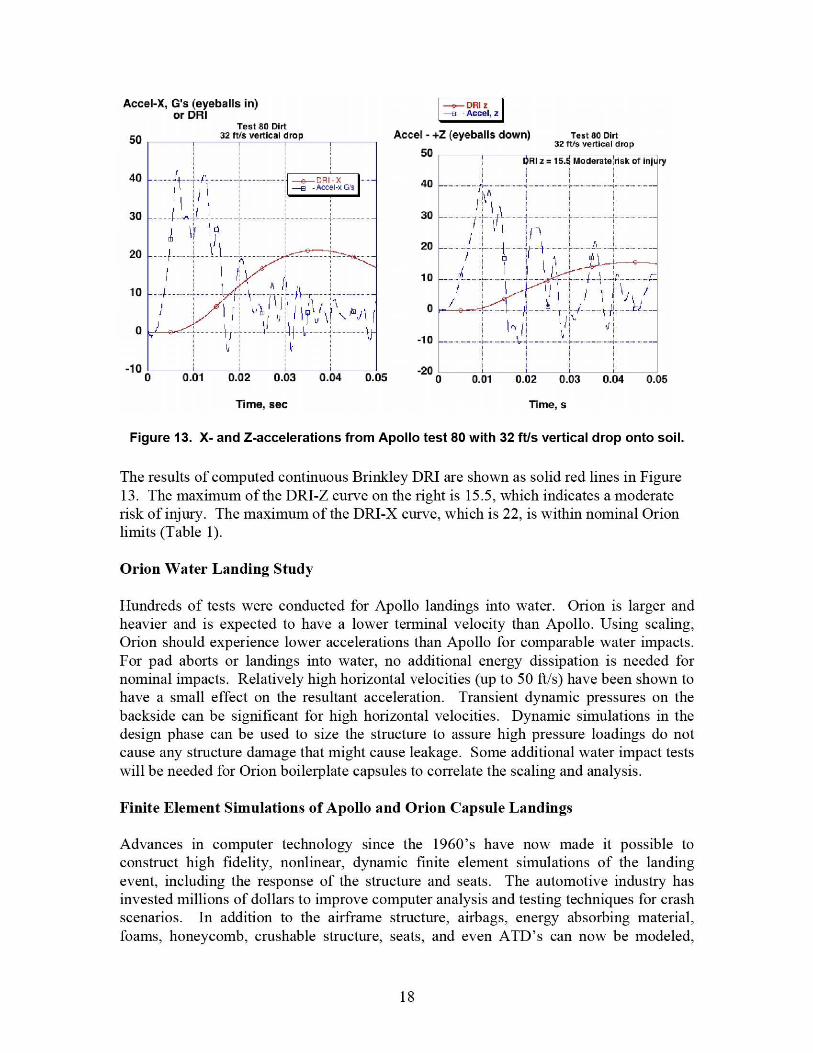
Figure 13. X- and Z-accelerations from Apollo test 80 with 32 ft/s vertical drop onto soil.
The results of computed continuous Brinkley DRI are shown as solid red lines in Figure13. The maximum of the DRI-Z curve on the right is 15.5, which indicates a moderaterisk of injury. The maximum of the DRI-X curve, which is 22, is within nominal Orionlimits (Table 1).
Orion Water Landing Study
Hundreds of tests were conducted for Apollo landings into water. Orion is larger andheavier and is expected to have a lower terminal velocity than Apollo. Using scaling,Orion should experience lower accelerations than Apollo for comparable water impacts.For pad aborts or landings into water, no additional energy dissipation is needed fornominal impacts. Relatively high horizontal velocities (up to 50 ft/s) have been shown tohave a small effect on the resultant acceleration. Transient dynamic pressures on thebackside can be significant for high horizontal velocities. Dynamic simulations in thedesign phase can be used to size the structure to assure high pressure loadings do notcause any structure damage that might cause leakage. Some additional water impact testswill be needed for Orion boilerplate capsules to correlate the scaling and analysis.
Finite Element Simulations of Apollo and Orion Capsule Landings
Advances in computer technology since the 1960's have now made it possible toconstruct high fidelity, nonlinear, dynamic finite element simulations of the landingevent, including the response of the structure and seats. The automotive industry hasinvested millions of dollars to improve computer analysis and testing techniques for crashscenarios. In addition to the airframe stricture, airbags, energy absorbing material,foams, honeycomb, crushable structure, seats, and even ATD's can now be modeled,
18

including important strain-rate effects that were neglected in the past. Considerableresearch has been conducted to develop human injury criteria for impact. Better analysismeans less testing is required. Once validated with test data, the computer codes cangreatly influence the final design.
New capabilities of dynamic finite element codes such as LS-DYNA (Hallquist, 2006)and other spin-offs of publicly developed DYNA31) continue to be developed. Thesecodes can simulate ballistic impacts and explosions, seats, occupants, full-scaleautomobile and airplane impacts, and fluid-structural interactions such as a capsule intowater or soft soil.
Separate simulation efforts will be discussed for water landing and land landing. In theApollo-era, finite element modeling techniques for structural impact were inadequate andtesting was the method of choice for verifying system performance. Currently, during thedesign phase, numerical modeling is the most logical and least expensive approach tostudy the effects of impact on a structure. With the advent of fast inexpensive workstationcomputers, numerical modeling of the impact of a structure into either a hard soil or afluid media such as water can be modeled with explicit nonlinear dynamic codes.Typically, the capsule structure and hard soil is modeled with Lagrangian meshescomposed of deformable elements with associated nodes that move with the element. Afluid such as water is typically modeled using a stationary Eulerian mesh in which thefluid material flows between elements, while conserving mass, momentum, and energy.When using an Eulerian fluid solver, a portion of the air volume above the water mustalso be modeled with an Eulerian mesh to allow the wave to form.
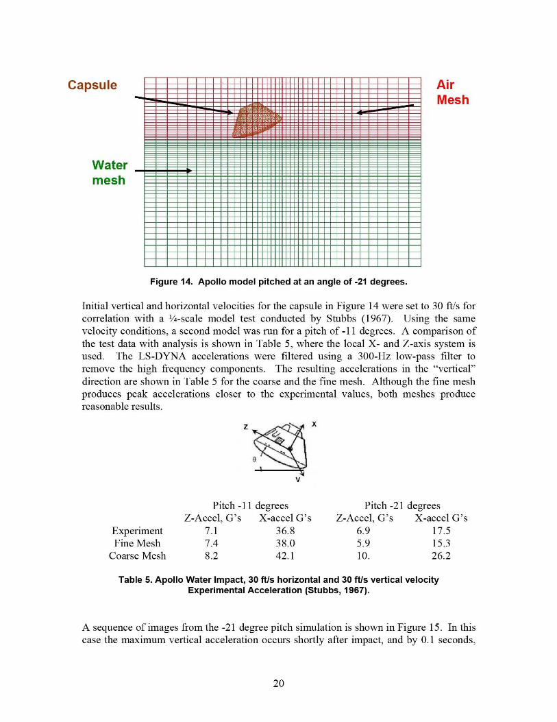
Water Landing Simulations ofApolloVarious schemes are typically used to model the fluid meshes and their interaction withthe structural mesh. In LS-DYNA, the meshes interact by the Arbitrary Lagrangian-Eulerian (ALE) coupling. In the ALE formulation, the Eulerian mesh and the Lagrangianmesh are coupled through an ALE interface surface. Although the Lagrangian andEulerian grid points are separate in the logical space, grid points on the interface surfacecoincide in physical space, and hence the ALE interface moves as the Lagrangianstructure deforms. The deformation of the structure at the ALE interface should berelatively smooth. Note, that smoothness does not require the deformation to be small inmagnitude. The LS-DYNA model of a rigid body Apollo Command Module within anEuler air and water mesh was used for the simulation and is shown in Figure 14. Arelatively coarse mesh with approximately 70,000 elements is shown, but a more refinedmesh with approximately 500,000 elements was also generated. In Apollo nomenclature,this orientation is called the 180-degree roll (heel-in). Orientations of -11, and -38degrees were also generated.
19
Capsule AirMesh
Watermesh
Figure 14. Apollo model pitched at an angle of -21 degrees.
Initial vertical and horizontal velocities for the capsule in Figure 14 were set to 30 ft/s forcorrelation with a 1/4-scale model test conducted by Stubbs (1967). Using the samevelocity conditions, a second model was nun for a pitch of -11 degrees. A comparison ofthe test data with analysis is shown in Table 5, where the local X- and Z-axis system isused. The LS-DYNA accelerations were filtered using a 300-Hz low-pass filter toremove the high frequency components. The resulting accelerations in the "vertical"direction are shown in Table 5 for the coarse and the fine mesh. Although the fine meshproduces peak accelerations closer to the experimental values, both meshes producereasonable results.
Z x
0
v
Pitch -11 degrees Pitch -21 degreesZ-Accel, G's X-accel G's Z-Accel, G's X-accel G's
Experiment 7.1 36.8 6.9 17.5Fine Mesh 7.4 38.0 5.9 15.3
Coarse Mesh 8.2 42.1 10. 26.2
Table 6. Apollo Water Impact, 30 ft/s horizontal and 30 ft/s vertical velocityExperimental Acceleration (Stubbs, 1967).
A sequence of images from the -21 degree pitch simulation is shown in Figure 15. In thiscase the maximum vertical acceleration occurs shortly after impact, and by 0.1 seconds,
20

the vertical acceleration is approximately zero. Meanwhile, the maximum horizontalacceleration occurs around 0.04 seconds and is reduced to approximately 0.5 g by 0.1seconds. Wang (2007) used LS-DYNA to simulate accelerations for a capsule with aflexible heat shield that deforms on water impact and found that the peak accelerationwas greater for a flexible heat shield. This result was confirmed by experimental testdata.
Time = 0
Time = 0.25 sec
Figure 15. LS-DYNA simulation for an Apollo Capsule impact into water at 21-degreespitch for horizontal and vertical velocity components of 30 ft/s.
Soil Impact SimulationsIn contrast to water, which has consistent mechanical properties, the properties of soil arehighly variable, especially for dynamic impacts. The microstructure of the soil, the sizeof the soil particles, and the void between particles or grains are very important. Thebearing pressure of soft soils can be as low as 10 psi, whereas for hard soils, the bearingpressure can be hundreds of psi. In addition, the same soil can behave quite differentlyfor dynamic impacts depending on the moisture content. The pores between the grainscan be filled with either highly compressible air or with water. There are cases fordynamic loading that the media within the pores will carry the majority of the load. Onthe other hand, the strength of coarse soil-materials such as sand and gravel come fromgravitational effects, and the materials essentially have no inherent constitutive law. Forsmall particle size soils, such as clays, constitutive equations do apply.
In LS-DYNA, soil was modeled using the Mats material model, where volumetric yieldis determined by a curve of pressure versus volumetric strain. The yield depends on theconfining pressure. Thus, in the lab, a series of compression tests are conducted eachwith a higher side-wall confining pressure. Once the data are manipulated, the shearfailure criteria in Mats has a pressure dependent failure strength of the form Ao + Alp+AZp' where the A's are coefficients determined from the triaxial test and "p" is the meanstress. If the yield is low, the Mats model gives fluid-like behavior. In the LS-DYNAmodels, a soft soil must be constrained on the sides to prevent flowing under a gravityloading.
Uncertainty in soil behavior prompted the Orion LS ADP to conduct soil testing at theoriginally proposed western landing sites for Orion. Soil at Carson Sink in Nevada was
21

typically quite soft, while the soil at Roger's Lake at Edwards Air Force Base, Californiawas very hard. Soil samples were collected and characterized in a soils laboratory usingthe triaxial compression strength test to generate input for LS-DYNA Mat5 materialmodels. In addition to the soil samples collected at each site, instrumented hemisphericalpenetrometers were dropped at various locations. The peak acceleration from thepenetrometer's acceleration time history is used as a relative indicator of the soil strength.At this point, two soil models have been developed; one for a very soft soil that isrepresentative of a dry unpacked sand that might be present in sand dunes, and the otherfor a relatively hard soil more representative of Edwards. Soft soils such as beach sandand the soils at Carson Sink near Fallon Nevada are ideal for a pure vertical velocity. Acomparison of acceleration time histories from 8-in diameter 20-pound penetrometerdrops from 30 inches with an LS-DYNA soft-soil model developed from data obtainedfrom the Utah Test and Training Range (UTTR) is shown in Figure 16. The soil atUTTR was noted to yield at a pressure of about 10 psi. Notice that the analysis isapproximately in the middle range of the data spread. A typical LS-DYNA penetrometermodel showing the discretization is illustrated in Figure 17. Similar drops onto hard soilat Edwards produced accelerations over 150 G's.
d5
40
35
M 30C
.2! 255V
20
4 15
10
5
0
! I ti -Analysis
^'^`^, -- Test
l ^
^J^i ^^1 ^^l
F^
I, 7frJar f̂ ^ k NN
NI
,
'^^ x11 11^
s FUh^ ^ kt t tS.a
1 + 1 M^1 1 I1 f l IJ 1^ ^. ^^ -^.
0 0.01 0.02 0.03 0.04 0.05
Time, s
Figure 16. Accelerometer traces from a 20 lb penetrometer dropped from 30 inches atFallon compared with LS-DYNA model (red curve).
Figure 17. LS-DYNA model of 20-inch penetrometer impacting onto soil.
22

Vertical Accel, g12 T
10
4
_2 1
.0.1 0 0.1 0.2 0.3 0.4 0.5 0.6
Vert Accei, g's6
5
4
3
2
1
0
_1
_2
Figure 18. Scaled boilerplate capsule model impacting onto soil.
In addition to the penetrometer tests, additional tests were conducted using a scaledboilerplate capsule. These tests were conducted onto soil at the LandIR facility at 58 ft/shorizontal velocity and 5 ft/s vertical velocity. For LS-DYNA modeling, the soil wasassumed to be soft with a 10-psi yield. During the simulations, the rigid body capsulemodel skipped across the soil leaving small craters as shown in Figure 18. Although thecraters were exaggerated over what was observed, the acceleration time history wascomparable as shown in Figure 19.
Time, sec Time,s
Figure 19. Accelerations of model (left) compared with initial test accelerations (right). Thetime is not to the same scale on the two plots.
Airbag Land Landing Simillations for OrionDuring the early design phase of the Orion landing system, concerns arose about airbagperformance on soft soils with relatively high horizontal winds. Of particular concernwas the plowing into the soil that could either shear the airbags from the Orion structureor lead to tumbling. Although a slow turn-over of the Orion capsule is not particularlybad, severe tumbling must be avoided to protect the cre`v from injury and to preventdamage that would prevent reusability. To illustrate turn-over, an LS-DYNA model for acapsule weighing 16,000 pounds with six airbags landing with a horizontal velocity of 40ft/s and a sink speed of 25 ft/s is shown lying on its side in Figure 20. The soil model inthis case was packed sand. Friction is a parameter that can be adjusted in the simulation.If the friction coefficient is lowered from 0.6 to 0.4, then the same model did not topple.However, for a dry unpacked sand with a friction coefficient of 0.4, the capsule modelagain topples for the same initial conditions. Testing will be required to verify thesepreliminary uncorrelated models.
23

Figure 20. Capsule with airbag tumbles for 40 ft/s horizontal velocity with 0.6 frictioncoefficient into soft soil.
Soil material models must be carefully developed and correlated with experiments todetermine the percent of dissipated and recoverable elastic energy in the soil model. Thehysteresis in the unloading curve determines the energy absorbed (dissipated) by the soil,and the portion that leads to rebound of the capsule (elastic energy). Another reason whya water landing produces lower accelerations is that rebound does not occur for mostimpact conditions. Also, the relatively high horizontal velocities for water only have asmall effect on the resultant acceleration.
Passive Energy Attenuating Systems
Although active systems such as retrorockets and airbags are effective and highlyreliable, for additional protection, passive systems such as crushable structure orcrushable foams should be used whenever possible. Similar to sacrificial structure at thefront of an automobile, the volume beneath the pressure vessel should incorporateproperly sized crushable stricture such as foam or honeycomb that will reduce theacceleration to the occupants. A properly designed heatshield can also be an effectivepassive energy absorber. Energy absorbing devices on each seat and/or on the seat palletare being developed for the safety of the crew, especially for off-nominal impacts.
Concluding Remarks
After retiring the Space Shuttle in 2010, NASA plans to replace the Space Shuttle orbiterwith the Orion spacecraft, a capsule that is larger than the Apollo command module withroom for up to six astronauts. Weight constraints are steering the current Orion designtowards water landings, but the design goal is for the Orion crew to "walk away" fromland landings due to a pad abort or for any other land landing. Consequently, landingsystems for Orion must be designed for multi-terrain impacts. Reusability of the capsuleis not a design requirement, but would be desirable.
This paper presented a survey of Apollo landing system design and testing plus anoverview of previously flown landing system technologies that use parachutes. Inparticular, the Soyuz, which uses retrorockets in landing, and the F-111 escape module,which used a large airbag beneath the capsule, were investigated in order to extractlessons applicable for Orion.
24

Finally, this paper presented representative test data generated at the NASA LandIR ofdevelopmental airbag landing systems for the Orion capsule. LS-DYNA simulations ofairbag systems impacting onto soft soil and of space capsules impacting into water werepresented. The primary goal of landing system research is to develop concepts toattenuate impact loads transmitted to the crew to noninjurious levels. Consequently,human tolerance to impact and Orion impact criteria were also discussed.
Safe, reliable, and effective landing system concepts can be developed to protect theOrion crew for impacts onto water, soft soil, and hard soil surfaces. The developmentprocess will be aided through the use of dynamic finite element analysis, new test datagenerated by ongoing experimental programs, and by incorporating lessons learned fromprevious landing systems. As was determined by the Apollo engineers, the simplest,lightest, and most reliable landing for a capsule such as Orion is a water landing. For aland landing, retrorockets appear to offer the lightest and most reliable active system.However, to meet reusability considerations, Orion has advanced airbag technology andhas extended the state of the art. The challenge for airbag systems is to provide earthlanding capability with high reliability and a low weight penalty.
Acknowledgements
The author would like to especially acknowledge the entire ADP staff at NASA Langleyfor providing experimental data and model results and for many discussions on Orionlanding systems. In particular, special thanks go to James Corliss, Barry Bryant, KarenLyle, Karen Jackson, Richard Boitnott, Ralph Buehrle, Robin Hardy, Lisa Jones, SotirisKellas, Brian Mason, Mercedes Reaves, and John Wang. James Brinkley providedinformation on human tolerance that was very helpful. Professor Ala Tablei and JohnWang provided water impact results. In addition, Jerry McCullough, who was the Apolloengineer in charge of soil impact tests, and Apollo astronaut, T. K. Mattingly, providedinsights that could not be found in any report.
References
Benson, Harold E., "Water Impact of the Apollo Spacecraft," AIAA Journal ofSpacecraft, Vol.3, No. 8, pp. 1282-1284, August 1966.
Benson, Harold E. and West, Robert E., "Results of Two One-Quarter Scale ApolloModel Impact Tests Utilizing Different Impact Attenuation Systems," NASA TMX-65129, January 1965.
Brinkley, James W., "Development of Aerospace Escape Systems," Air UniversityReview, July — August, 1968.
Brinkley, J. W., and Moser, S. E., "Development of Acceleration Exposure Limits forAdvanced Escape Systems," AGARD CP-472, April 1989.
Bolukbasi, Akif, "Active Crash Protection Systems for UAVs," American HelicopterSociety Annual Forum 63 Proceedings, Virginia Beach, VA, May 1-3, 2007.
Chambers, J. R., "Partners in Freedom: Contributions of the Langley Research Center to
25

U. S. Military Aircraft of the 1990s," NASA SP-2000-4519, Monographs in AerospaceHistory Number 19, p.61-81,2000.
Eiband, A. Martin, "Human Tolerance to Rapidly Applied Accelerations: A Summary ofthe Literature," NASA Memorandum 5-19-59E, June 1959.
Hallquist, John O., "LS-DYNA Theory Manual," Livermore Software TechnologyCorporation, Livermore, CA, ISBN 0-9778540-0-0, March 2006.
Jones, R. H., "Landing Impact Attenuation for Non-Surface-Planing Landers," NASASP-8046, April 1970.
McGehee, J. R., Hathaway, M. E., and Vaughan, V. L, "Water Landing Characteristics ofa Reentry Capsule," NASA Memo 5-23-59L (1959).
McCullough, J. E., and Lands, Jr., F. F., "Apollo Command Module Land-Impact Tests,"NASA TN D-6979, October 1972.
Mears, Allen K., "Report on the Effects of Parachutes on Risk Mitigation to Third-PartyProperty and Individuals, Futron Corporation, prepared for Office of CommercialSpace Transportation, March 1993.
Obert, James E., "Consultant Report — Soyuz Landing Safety, Soyuz Landing HistoricalReliability Study," www.jamesobera.com/Soyuz.html, March 19, 1997.
Sarigul-Klijn, M. and Sarigul-Klign, N., "Flight Mechanics of Manned Sub-OrbitalReusable Launch Vehicles with Recommendations for Launch and Recovery," AIAA-2003-0909, September 2003.
St. Vaughan, Joshua A., Singh, Gurkirpal, Prakash, Ravi, Frisbee, Robert H. Corliss,James M., and Tutterow, Robin, "Design of a Retro Rocket Earth Landing system forthe Orion Spacecraft," 2007 IEEE Aerospace Conference, March 3-10, 2007, p1-12.
Stubbs, Sandy M., "Dynamic Model Investigation of Water Pressures and AccelerationsEncountered During Landings of the Apollo Spacecraft," NASA TND-3980, Sept. 1967.
Vaughan, Victor L., Jr. and Alfaro-Bou, Emilio, "Impact Dynamics Research Facility forFull-Scale Aircraft Crash Testing." NASA TN D-8179, 1976.
Wang, John T. and Lyle, Karen H., "Simulating Space Capsule Water Landing withExplicit Finite Element Method," 48 th AIAA Structures, Structural Dynamics, andMaterials Conference Proceedings, Hawaii, 2007.
West, Robert B., "Apollo Experience Report — Earth Landing System," NASA TN D-7437, November 1973.
Wilkinson, J.P.D, "Study of Apollo Water Impact," SID 67-498, Volume 4, May 1967.
Yosuf, V., BenMoshe, A., Noyman, Y., Gansman, Bob, and Bradney, Chris, "RotorcraftExternal Airbag Protection System," American Helicopter Society Annual Form 62Proceedings, Phoenix, AZ, May 9-11, 2006.
26