multiband folded loop antenna for smart phones c · pdf filemultiband folded loop antenna for...
TRANSCRIPT
Progress In Electromagnetics Research, PIER 102, 213–226, 2010
MULTIBAND FOLDED LOOP ANTENNA FOR SMARTPHONES
C.-W. Chiu and C.-H. Chang
Department of Electronic EngineeringNational Ilan UniversityIlan 260, Taiwan
Y.-J. Chi
Department of Electrical EngineeringNational Chiao-Tung UniversityHsinchu 350, Taiwan
Abstract—This paper presents a multiband folded loop antennafor smart phone applications. The proposed antenna with asymmetric loop pattern generates four resonance modes in the designbands. The current distributions of the excited resonance modesare analyzed to confirm the mode characteristic. Using a pair oftuning elements near the feed port, the impedance bandwidth isbroadened to cover GSM850/GSM900/DCS/PCS/UMTS bands. Thisresearch performed simulation by a high frequency structure simulator(HFSS) to optimally design the antenna, and a practical structurewas constructed to test. The current study measured the antennaparameters including reflection coefficient, radiation characteristics,peak gain, and radiation efficiency to validate the proposed antenna.
1. INTRODUCTION
The demand for multisystem handset equipment has recently increasedrapidly. The design of a wireless transceiver in a smart phone ora portable device must support multisystem operations. Currently,multiband operation is almost a common standard. Therefore, theantenna embedded in the mobile phone or smart phone must becapable of operating at four or more frequency bands, at least including
Corresponding author: C.-W. Chiu ([email protected]).
214 Chiu, Chang, and Chi
GSM850/900 (824–960MHz), DCS (1710–1880 MHz), PCS (1850–1990MHz), UMTS (1920–2170 MHz). Moreover, internal antennasmust have small size, weight, a low profile and as low cost as possible.
Much effort has been devoted to the multiband internal antennaduring the past decade, such as planar inverted-F antennas (PIFA),inverted-F antennas (IFA), patch antennas and loop antennas [1]. Theconventional PIFA, IFA, and their variants have become popular inmost handsets and portable devices for mobile phone applications.This is mainly due to their miniature size, easy fabrication, and lowcost [2, 3]. To achieve a wide bandwidth in the GSM850/900 band, thesystem ground plane of a PIFA or IFA acts as part of the antenna,thereby improving the bandwidth and gain performance [4–9]. This isnecessary, especially as the mobile device is quite small. However,the current variation due to the device being hand-held and theresulting body proximity effect degrades antenna performance since theresonating currents are spread out over the system ground plane [1, 10].To avoid degrading antenna performance, a printed loop antenna isanother candidate for the mobile phone since the current induced onthe ground plane is small [11–17].
This paper presents a folded loop antenna with multibandcharacteristics for smart phone applications. The proposed antennais mounted on a printed circuit board. The proposed designapplies a pair of rectangular tuning elements near the feed portto adjust resonance modes to cover the mentioned standards:GSM850/GSM900/DCS/PCS/UMTS. The occupied space of thefolded loop antenna measures 60 mm× 10 mm ×8mm. The maincurrent is limited in the closed loop pattern and feed port area so thatthe current on the ground plane is small. Radiation degradation fromthe antenna system is reduced as the human head and hand are in thevicinity [15]. Details of the proposed antenna as well as experimentalresults are shown below.
2. ANTENNA DESIGN
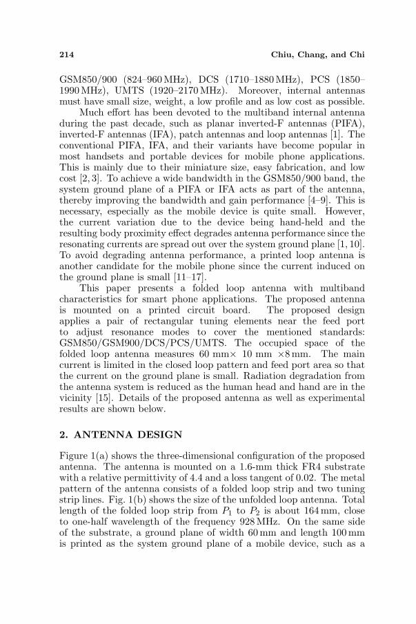
Figure 1(a) shows the three-dimensional configuration of the proposedantenna. The antenna is mounted on a 1.6-mm thick FR4 substratewith a relative permittivity of 4.4 and a loss tangent of 0.02. The metalpattern of the antenna consists of a folded loop strip and two tuningstrip lines. Fig. 1(b) shows the size of the unfolded loop antenna. Totallength of the folded loop strip from P1 to P2 is about 164 mm, closeto one-half wavelength of the frequency 928MHz. On the same sideof the substrate, a ground plane of width 60mm and length 100 mmis printed as the system ground plane of a mobile device, such as a
Progress In Electromagnetics Research, PIER 102, 2010 215
(a)
(b)
Figure 1. Geometry of the proposed antenna: (a) 3D View. (b) Planview of the front-side.
smart phone. To increase electric length and support the folded loop,two tuning strip lines A and B are inserted into the loop. A pair ofrectangular tuning elements is placed near the feed port to broadenthe impedance bandwidth. The antenna is fed by a 50 ohm semi-grid

216 Chiu, Chang, and Chi
0.5 1 1.5 2 2.5 3 3.5
Frequency (GHz)
-30
-25
-20
-15
-10
-5
0
Reflection C
oeeffic
ient (d
B)
original loop
-6dB
1.01
1.66 2.16
3.36
Figure 2. Simulated results of the reflection coefficient for the originalloop pattern.
coaxial cable. The center conductor of the cable launches the signalfrom the left-side strip terminal P1 at the feed point and the outerconductor of the cable is affixed to the right-side strip end P2 whichterminates to the ground plane.
The antenna system has a symmetric loop pattern but anunbalanced feeding scheme. The antenna system generates fourresonance modes below 3.5GHz. Even modes and odd modes can besimultaneously excited on this antenna system. Fig. 2 shows simulationresults for the reflection coefficient without the tuning element andthe tuning strip lines by Ansoft’s HFSS, an EM simulator. The firstresonance at 1.01 GHz is an even mode (one-half wavelength mode)and the third resonance at 2.16 GHz is its higher mode. The secondresonance at 1.66GHz is an odd mode (one-wavelength mode) and thefourth resonance at 3.36 GHz is its higher order mode [17].
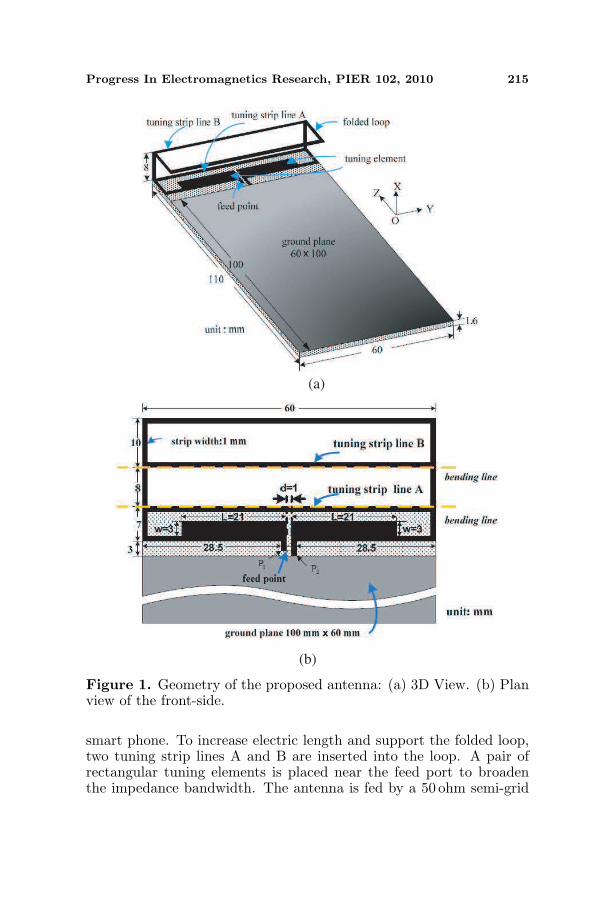
Surface current distributions on the conductor strip confirmthe mode characteristic. Fig. 3 shows the vector surface currentdistributions and current densities on the loop pattern at the fourresonance frequencies 1.01, 1.66, 2.16 and 3.36 GHz, respectively. Thecurrent distributions shown in Figs. 3(a) and (c) are equal in magnitudebut in the opposite direction since the loop pattern is symmetric fromthe side with respect to the line pp′. This behavior implies thatthe unbalanced feeding scheme excites the even modes. The currentdistribution shown in Fig. 3(c) has three nulls so that it is a 1.5-wavelength mode [15]. The currents shown in Figs. 3(b) and (d) showa differential behavior in the feed port. The currents are equal inamplitude and in the same direction respective to qq′. This behaviorexhibits that they are odd modes. They are the traditional one- andtwo-wavelength loop modes [15]. The antenna at the second resonance
Progress In Electromagnetics Research, PIER 102, 2010 217
(a) 1.01 GHz (b) 1.66 GHz
(c) 2.16 GHz (d) 3.36 GHz
Figure 3. Simulated vector current distributions and surface currentdensities.
looks like a differential folded dipole since the currents at 1.66 GHzflow in the same direction for all the strips.
3. BANDWIDTH ENHANCEMENT
To cover the bandwidth for UMTS system application, somebandwidth enhancement techniques must be applied to broaden theimpedance bandwidth in the higher band. The folded antenna is athree-dimensional structure where the strip width is only 1 mm so thatit must have a solid support. To stably support the 3-D antenna,two tuning strip lines A and B are inserted into the loop and bent atthe upper and lower folding corners, as shown in Figs. 1(a) and (b).The main purpose of inserting the tuning strip lines is to increase theelectrical length of resonant frequency at the lower band. Fig. 4 showsthe influence of the strip lines A and B on the reflection coefficient. The

218 Chiu, Chang, and Chi
0.5 2 2.5 3 3.5
Frequency (GHz)
-35
-30
-25
-20
-15
-10
-5
0
Reflection C
oeeffic
ient (d
B)
1.51
Figure 4. Frequency shiftingdown with inserted tuning striplines.
-30
-25
-20
-15
-10
-5
0
0.5 2 2.5 3 3.5
Frequency (GHz)
1.51
Reflection C
oeeffic
ient (d
B)
Figure 5. Simulated results as afunction of the distance d betweenthe pair of tuning elements.
finding shows that the first resonance frequency shifts from 1.01 GHzto 0.86 GHz. The electric length of the one-half wavelength increasessince the input impedance is capacitive in the low band. However,resonant frequency of the one-wavelength differential mode shifts tohigher frequencies because shunting an inductance in the loop patterndecreases the parallel inductance and then reduces total electricallength of the series-resonance loop mode. Adding the tuning strip lineB generates a new resonance mode at the resonant frequency 2.3GHz.The current distribution which has three nulls on the loop pattern issimilar to the distribution shown in Fig. 3(c). The new mode is a 1.5-wavelength mode of the closed loop where the current flows throughthe tuning strip line B.
Although the folded antenna generates three resonance modes inthe higher band, the achieved bandwidth is not wide enough to coverDCS, PCS, and UMTS bands. To obtain better impedance matchingin the higher band, a pair of tuning elements shown in Fig. 1(b) isadhered to the loop strip near the feed port. Investigating the currentdistribution shown in Figs. 3(a) and (b) decides the tuning elementposition. Since the current is strong near the feed port, impedancematching is easier to achieve by placing the tuning element near thisarea. Varying the location d, width w and length L of the tuningelement helps achieve impedance matching over the design bands.Fig. 5 shows the position influence of the tuning element on antennaperformance when the distance d varies from 1 to 13 mm. The positiontuning for the pair of tuning element is controlled by the distance d.The symmetric feature is preserved here and the length L and the widthw are fixed. The finding shows that the position influence is larger in

Progress In Electromagnetics Research, PIER 102, 2010 219
-20
-15
-10
-5
0
0.5 2 2.5 3 3.5
Frequency (GHz)
1.51
Re
fle
ctio
n C
oe
eff
icie
nt
(dB
)
Figure 6. Simulated results as afunction of width w of the tuningelement.
-30
-25
-20
-15
-10
-5
0
0.5 2 2.5 3 3.5
Frequency (GHz)
1.51
Re
fle
ctio
n C
oe
eff
icie
nt
(dB
)
Figure 7. Simulated results as afunction of length L of the tuningelement.
the high band than in the low band. When the tuning element islocated near the middle (d = 1 mm), impedance matching is good forcovering GSM850/GSM900/DCS/PCS/UMTS operation.
This research also conducted a parametric study on the width wand the length L. When the parameter w varies from 2 to 4mm orthe parameter L varies from 16 to 26 mm, other dimensions of theantenna are the same as shown in Fig. 1. Fig. 6 shows the simulationreflection coefficient as a function of width w. The width variation doesnot influence impedance matching in the low band but findings showlarger effects in the higher band. When the width w is fixed as 3mm,the impedances are well matched in the higher band. Fig. 7 shows theeffects of length L on antenna performance. Observations show largereffects on the first resonance mode. The longer the length, the greaterthe bandwidth. When the length is increased to about 21 mm, thebandwidths in the low band and higher band achieve the SWR < 3bandwidth requirement.
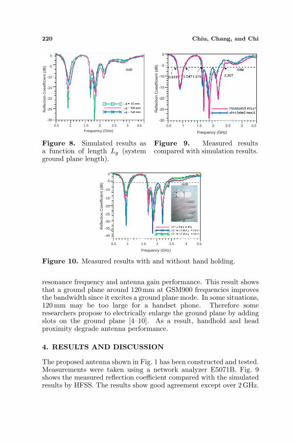
The current work also studies the proposed antenna with differentground-plane lengths Lg. Fig. 8 shows simulated results for length Lg
variations from 80 to 120. The finding shows that the bandwidth ofthe low band becomes broader when length Lg increases. Bandwidthsin the low band for Lg = 80 mm and Lg = 120 mm are 160 MHzand 250 MHz, respectively. The bandwidth for Lg = 80mm is still72% of that for Lg = 100 mm. Center resonance frequency in thelow band is slightly influenced by ground plane length. TraditionalPIFA has a quarter-wavelength shorted patch and a finite groundplane [10]. The ground plane acts as part of a resonator in the lowerband. Ground plane size has strong effect on impedance matching,
220 Chiu, Chang, and Chi
0.5 2 2.5 3 3.5
Frequency (GHz)1.51
-30
-25
-20
-15
-10
-5
0
Ref
lect
ion
Coe
effic
ient
(dB
)
-6dB
Figure 8. Simulated results asa function of length Lg (systemground plane length).
0.5 2 2.5 3 3.5
Frequency (GHz)
1.51
-30
-25
-20
-15
-10
-5
0
Reflection C
oeeffic
ient (d
B)
Figure 9. Measured resultscompared with simulation results.
0.5 2 2.5 3 3.5
Frequency (GHz)
1.51
-30
-25
-20
-15
-10
-5
0
Ref
lect
ion
Coe
effic
ient
(dB
) -6dB
-40
-35
Figure 10. Measured results with and without hand holding.
resonance frequency and antenna gain performance. This result showsthat a ground plane around 120 mm at GSM900 frequencies improvesthe bandwidth since it excites a ground plane mode. In some situations,120mm may be too large for a handset phone. Therefore someresearchers propose to electrically enlarge the ground plane by addingslots on the ground plane [4–10]. As a result, handhold and headproximity degrade antenna performance.
4. RESULTS AND DISCUSSION
The proposed antenna shown in Fig. 1 has been constructed and tested.Measurements were taken using a network analyzer E5071B. Fig. 9shows the measured reflection coefficient compared with the simulatedresults by HFSS. The results show good agreement except over 2GHz.

Progress In Electromagnetics Research, PIER 102, 2010 221
Findings show some differences beyond 2 GHz because of some losseffect on the substrate. The bandwidth achieved with the reflectioncoefficient better than −6 dB is 228 MHz (0.819–1.047 GHz) in thelower band and 718 MHz (1.679–2.397 GHz) in the DCS/PCS/UMTSband. (The internal antenna for general mobile phone applicationsis typically designed based on the bandwidth definition of −6 dBreflection coefficient).
This work also studied the effects of user’s hand-hold on themobile phone with the proposed antenna [11, 18–21]. The distancer from the top edge of the ground plane to the top rim of the user’sthumb portion is about 20mm and 40mm, respectively. Fig. 10 shows
X-Y plane
(a) 860MHz (b) 925MHz
(c) 1795MHz
(d) 1920MHz (e) 2045MHz
Figure 11. Measured radiation patterns at 860 MHz, 925 MHz,1.795GHz, 1.92 GHz, and 2.045 GHz, respectively.
222 Chiu, Chang, and Chi
the measured results when hand-holding the antenna. The figurealso shows the measured results without hand-holding. The smallerfrequency detuning indicates that loop antenna performance is lessdependent on the ground plane. Since the proposed antenna hasbalance features and less currents on the ground plane, the handheldinfluence of the loop antenna on impedance matching is less than thatof the planar inverted-F antenna.
The radiation-pattern and gain measurement were performed inthe anechoic chamber of SGS Ltd., Taiwan. Fig. 11 plots the measuredradiation patterns at 860MHz, 925 MHz, 1.795 GHz, 1.92GHz, and2.045GHz for the proposed antenna. At 925 MHz, the radiationpattern has a dipole-like feature. Findings show more variations forthe radiation pattern in the higher band, since high order modes aregenerated in the higher band. A nearly omni-directional radiationpattern was found on the XY -plane. The feature is very suitable formobile phones.
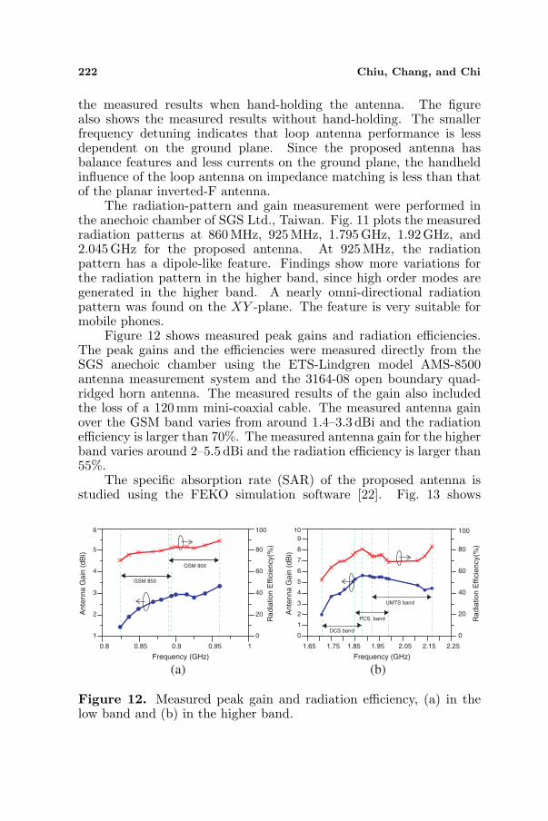
Figure 12 shows measured peak gains and radiation efficiencies.The peak gains and the efficiencies were measured directly from theSGS anechoic chamber using the ETS-Lindgren model AMS-8500antenna measurement system and the 3164-08 open boundary quad-ridged horn antenna. The measured results of the gain also includedthe loss of a 120 mm mini-coaxial cable. The measured antenna gainover the GSM band varies from around 1.4–3.3 dBi and the radiationefficiency is larger than 70%. The measured antenna gain for the higherband varies around 2–5.5 dBi and the radiation efficiency is larger than55%.
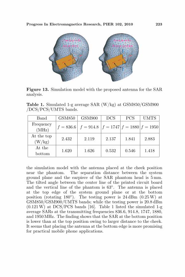
The specific absorption rate (SAR) of the proposed antenna isstudied using the FEKO simulation software [22]. Fig. 13 shows
0.8 0.85 0.9 0.95 1
Frequency (GHz)
1
2
3
4
5
6
An
ten
na
Ga
in (
dB
i)
0
20
40
60
80
100
GSM 850
GSM 900
(a)
1.65 1.75 1.85 1.95 2.05 2.15 2.25
Frequency (GHz)
0
1
2
3
4
5
6
7
8
9
10
An
ten
na
Ga
in (
dB
i)
0
20
40
60
80
100
Ra
dia
tio
n E
ffic
ien
cy(%
)
DCS band
PCS band
UMTS band
(b)
Ra
dia
tio
n E
ffic
ien
cy(%
)
Figure 12. Measured peak gain and radiation efficiency, (a) in thelow band and (b) in the higher band.
Progress In Electromagnetics Research, PIER 102, 2010 223
Figure 13. Simulation model with the proposed antenna for the SARanalysis.
Table 1. Simulated 1-g average SAR (W/kg) at GSM850/GSM900/DCS/PCS/UMTS bands.
Band GSM850 GSM900 DCS PCS UMTSFrequency
(MHz)f = 836.6 f = 914.8 f = 1747 f = 1880 f = 1950
At the top(W/kg)
2.432 2.119 2.137 1.841 2.883
At thebottom
1.620 1.626 0.532 0.546 1.418
the simulation model with the antenna placed at the cheek positionnear the phantom. The separation distance between the systemground plane and the earpiece of the SAR phantom head is 5mm.The tilted angle between the center line of the printed circuit boardand the vertical line of the phantom is 63◦. The antenna is placedat the top edge of the system ground plane or at the bottomposition (rotating 180◦). The testing power is 24 dBm (0.25 W) atGSM850/GSM900/UMTS bands; while the testing power is 20.8 dBm(0.121W) at DCS/PCS bands [16]. Table 1 listed the simulated 1-gaverage SARs at the transmitting frequencies 836.6, 914.8, 1747, 1880,and 1950 MHz. The finding shows that the SAR at the bottom positionis lower than at the top position owing to larger distance to the cheek.It seems that placing the antenna at the bottom edge is more promisingfor practical mobile phone applications.

224 Chiu, Chang, and Chi
5. CONCLUSION
This paper presented a folded loop antenna with five-bandcharacteristics. Four resonance modes are excited on the symmetricloop pattern in the design band. The proposed antenna utilizes apair of tuning elements coated on the printed circuit board to achievewideband performance. The design parameters of the folded loopantenna are optimized using Ansoft’s HFSS software and a practicalstructure is constructed to test. Measured parameters includingreflection coefficient, radiation patterns, peak gain, and radiationefficiency are presented to validate the proposed design. The loopantenna is less dependent on the ground plane so that antennaperformance is less influenced by hand-holding the device and headproximity. The structure is very suitable for portable device and canbe readily integrated in a smart phone.
ACKNOWLEDGMENT
We are grateful to the National Center for High-performanceComputing for the HFSS computer time and use of facilities. Also,the authors would like to thank Mr. Cheng-Chang Chen, Bureau ofStandards, Metrology and Inspection, M.O.E.A, Taiwan, for his helpin the SAR simulation using the FEKO simulation tool.
REFERENCES
1. Morishita, H., Y. Kim, and K. Fujimoto, “Design concept ofantenna for small mobile terminals and the future perspective,”IEEE Transactions on Antennas and Propagation, Vol. 55, No. 5,30–43, Oct. 2002.
2. Chi, Y. J., C. W. Chiu, and S. M. Deng, “Internal quad-bandprinted antenna for PDA phone,” Electronics Letters, Vol. 45,No. 10, 489–491, May 2009.
3. Chiu, C. W. and Y. J. Chi, “Planar hexa-band inverted-F antennafor mobile device applications,” IEEE Antenna and WirelessPropagation Letters, Vol. 8, 1099–1102, 2009.
4. Hossa, R., A. Byndas, and M. E. Bialkowski, “Improvement ofcompact terminal antenna performance by incorporating open-endslots in ground plane,” IEEE Microwave and Wireless ComponentLetters, Vol. 14, No. 6, 283–285, Jun. 2004.
5. Abedin, M. F. and M. Ali, “Modifying the ground plane and itseffect on planar inverted-F antennas (PIFAs) for mobile phone
Progress In Electromagnetics Research, PIER 102, 2010 225
handsets,” IEEE Antennas and Wireless Propagation Letters,Vol. 2, 226–229, 2003.
6. Anguera, J., I. Sanz, A. Sanz, A. Condes, D. Gala, C. Puente,and J. Soler, “Enhancing the performance of handset antennas bymeans of groundplane design,” IEEE International Workshop onAntenna Technology: Small Antennas and Novel Metamaterials(IWAT), 29–32, New York, USA, Mar. 2006.
7. Cabedo, A., J. Anguera, C. Picher, M. Ribo, and C. Puente,“Multi-band handset antenna combining PIFA, slots, and groundplane modes,” IEEE Transactions on Antennas and Propagation,Vol. 57, No. 9, 2526–2533, Sep. 2009.
8. Picher, C., J. Anguera, A. Cabedo, C. Puente, and S. Kahng,“Multiband handset antenna using slots on the ground plane:Considerations to facilitate the integration of the feedingtransmission line,” Progress In Electromagnetics Research C,Vol. 7, 95–109, 2009.
9. Antonino, E., C. A. Suarez, M. Cabedo, and M. Ferrando,“Wideband antenna for mobile terminals based on the handsetPCB Resonance,” Microwave and Optical Technology Letters,Vol. 48, No. 7, 1408–1411, Jul. 2006.
10. Vainikainen, P., J. Ollikainen, O. Kivekas, and K. Kelander,“Resonator-based analysis of the combination of mobile handsetantenna and chassis,” IEEE Transactions on Antennas andPropagation, Vol. 50, No. 10, 1433–1444, Oct. 2002.
11. Morishita, H., H. Furuuchi, and K. Fujimoto, “Performance ofbalanced-fed antenna system for handsets in the vicinity of ahuman head or hand,” IEE Proceedings on Microwave, Antennasand Propagation, Vol. 149, No. 2, 85–91, Apr. 2002.
12. Jung, B., H. Rhyu, Y. J. Lee, F. J. Harackiewwicz, M. J. Park,and B. Lee, “Internal folded loop antenna with tuning notches forGSM/GPS/DCS/PCS mobile handset applications,” Microwaveand Optical Technology Letters, Vol. 48, No. 8, 1501–1504,Aug. 2006.
13. Lin, C. I. and K. L. Wong, “Internal meandered loop antenna forGSM/DCS/PCS multiband operation in a mobile phone with theuser’s hand,” Microwave and Optical Technology Letters, Vol. 49,No. 4, 759–765, Apr. 2007.
14. Chi, Y. W. and K. L. Wong, “Internal compact dual-band printedloop antenna for mobile phone application,” IEEE Transactionson Antennas and Propagation, Vol. 55, No. 5, 1457–1462,May 2007.
15. Wong, K. L. and C. H. Huang, “Printed loop antenna with
226 Chiu, Chang, and Chi
a perpendicular feed for penta-band mobile phone application,”IEEE Transactions on Antennas and Propagation, Vol. 56, No. 7,2138–2141, Jul. 2008.
16. Chi, Y. W. and K. L. Wong, “Compact multiband folded loopchip antenna for small-size mobile phone,” IEEE Transactions onAntennas and Propagation, Vol. 56, No. 12, 3797–3803, Dec. 2008.
17. Chi, Y. J. and C. W. Chiu, “An internal hepta-band printed loopantenna for laptop computer,” Proc. IEEE AP-S Int. Symp.,Jun. 2009.
18. Boyle, K. R., Y. Yuan, and L. P. Lighthart, “Analysis of mobilephone antenna impedance variations with user proximity,” IEEETransactions on Antennas and Propagation, Vol. 55, No. 2, 364–372, Feb. 2007.
19. Huang, T. and K. R. Boyle, “User interaction studies on handsetantennas,” The Second European Conference on Antennas andPropagation, Nov. 2007.
20. Arenas, J. J., J. Anguera, and C. Puente, “Balanced andsingle-ended handset antennas: Free space and human loadingcomparison,” Microwave and Optical Technology Letters, Vol. 51,No. 9, 2248–2254, Sep. 2009.
21. Anguera, J., A. Camps, A. Anduar, and C. Puente, “Enhancingthe robustness of handset antennas to finger loading effects,”Electronics Letters, Vol. 45, No. 15, 770–771, Jul. 2009.
22. FEKO, EM Software & Systems-S.A. (Pty) Ltd (EMSS) [Online].Available: http://www.feko.info.