multifunctional time delay relay
TRANSCRIPT
NOVATEK-ELECTRO LTDintellectual commercial electronics
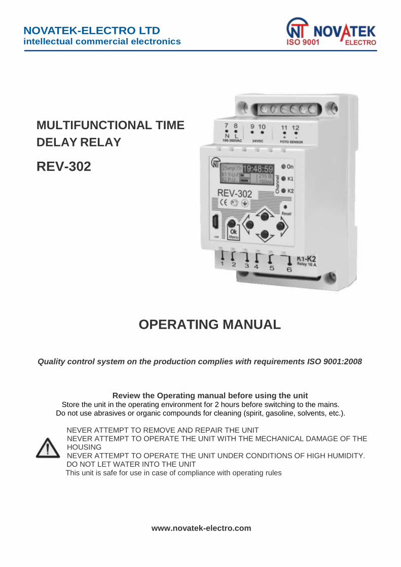
MULTIFUNCTIONAL TIME
DELAY RELAY
REV-302
OPERATING MANUAL
Quality control system on the production complies with requirements ISO 9001:2008
Review the Operating manual before using the unit
Store the unit in the operating environment for 2 hours before switching to the mains. Do not use abrasives or organic compounds for cleaning (spirit, gasoline, solvents, etc.).
NEVER ATTEMPT TO REMOVE AND REPAIR THE UNIT
NEVER ATTEMPT TO OPERATE THE UNIT WITH THE MECHANICAL DAMAGE OF THE HOUSING
NEVER ATTEMPT TO OPERATE THE UNIT UNDER CONDITIONS OF HIGH HUMIDITY. DO NOT LET WATER INTO THE UNIT
This unit is safe for use in case of compliance with operating rules
www.novatek-electro.com
- 2 -
REV-302 NOVATEK-ELECTRO
This manual has been developed as introduction to the design, operating principle, working procedures and settings of the multifunctional REV-302 relay.
1 DESCRIPTION AND OPERATION The REV-302 multi-functional relay is a microprocessor-based programmable device designed to
energize/de-energize one or two loads within user-set time intervals based on the circuit voltage and the external photo sensor luminance.
1.1 GENERAL
The REV-302 specific features: 2 switching contact groups of 16A rated current at 250V switching AC voltage. Power supply: 240V/50Hz AC or 24V DC. Time relay, voltage relay and photo relay combined or independent operation. Flexible contact switching control between the voltage relay, the photo relay and the time relay. 8 independent control programs and capability of swift transfer between them for each contact group. Capability to control both contact groups with a single program. 10 year calendar standalone power supply. Daily, weekly, monthly, and yearly time relay program. Independent events settings for each program. Programmable holiday and day off list option. Specific timer listing execution for days off and holidays. Common internal memory for 5000 independent events distributed between all programs for
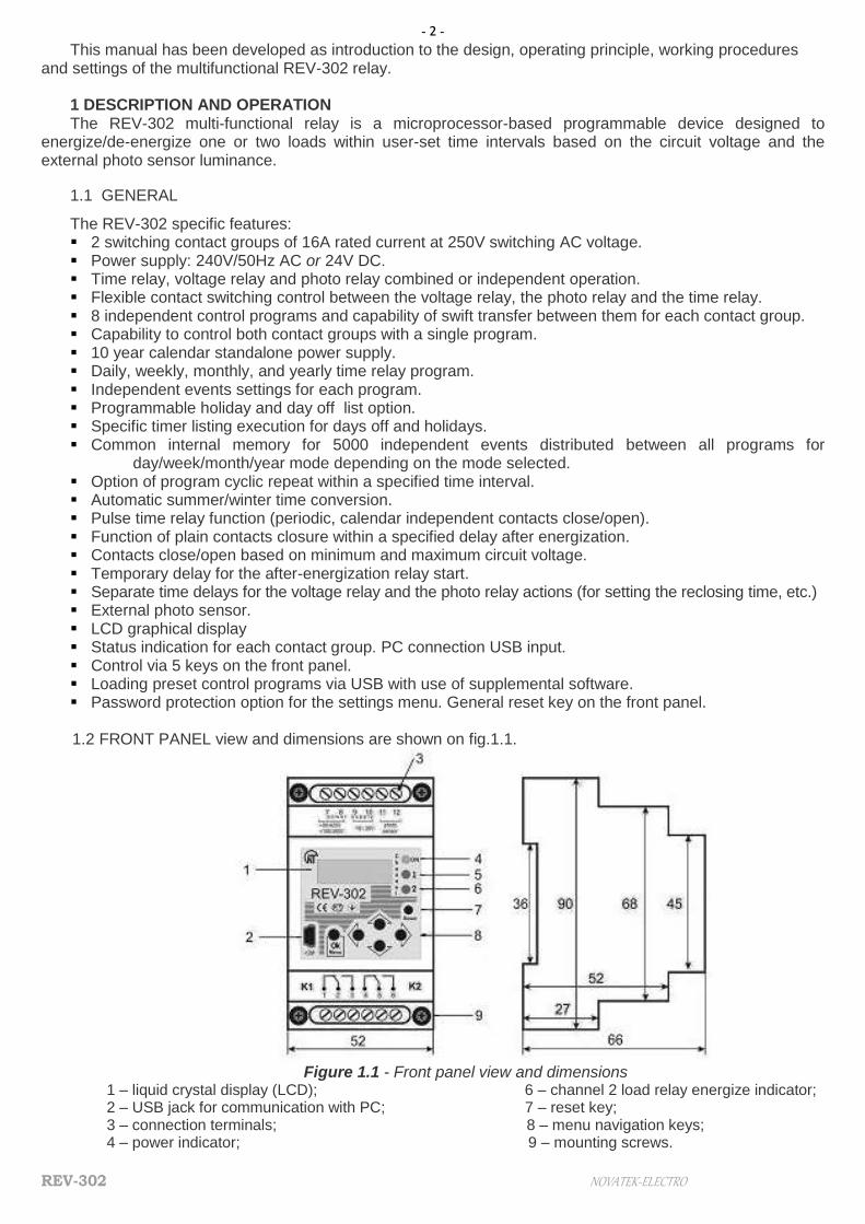
day/week/month/year mode depending on the mode selected. Option of program cyclic repeat within a specified time interval. Automatic summer/winter time conversion. Pulse time relay function (periodic, calendar independent contacts close/open). Function of plain contacts closure within a specified delay after energization. Contacts close/open based on minimum and maximum circuit voltage. Temporary delay for the after-energization relay start. Separate time delays for the voltage relay and the photo relay actions (for setting the reclosing time, etc.) External photo sensor. LCD graphical display Status indication for each contact group. PC connection USB input. Control via 5 keys on the front panel. Loading preset control programs via USB with use of supplemental software. Password protection option for the settings menu. General reset key on the front panel. 1.2 FRONT PANEL view and dimensions are shown on fig.1.1.
Figure 1.1 - Front panel view and dimensions 1 – liquid crystal display (LCD); 6 – channel 2 load relay energize indicator; 2 – USB jack for communication with PC; 7 – reset key; 3 – connection terminals; 8 – menu navigation keys; 4 – power indicator; 9 – mounting screws.

- 3 -
NOVATEK-ELECTRO REV-302
5 – channel 1 load relay energize indicator;
1.3 TECHNICAL BRIEF
Table 1.1 - The basic technical parameters
AC voltage (terminals 7-8), V 90 ÷ 420
DC voltage (terminals 7-8), V 100 ÷ 300
Rated DC voltage (terminals 9-10), V 8 ÷ 30
Supply curcuit frequency range, Hz 50/60
Internal fuse available
Max number of events 5000
Clock error, sec/day, sec, not more then 1
Clock standalone operation, when de-energized, years, no less than 10
Setting accuracy, sec 1
Voltage tripping threshold setting accuracy, V 1
Voltage measurement error, %, not more then 2
Illumination intensity measurement error up to 200 lx, %, not more then 10
Illumination intensity measurement error over 200 lx, %, not more then 20
Minimum time for the time relay contacts switching, sec 0,015
Minimum time for the voltage relay contacts switching, sec 0,035
Minimum time for the photo relay contacts switching, sec 0,1
Voltage lower tripping threshold setting range, Umin,V 90-416, but not more then Umax–dUmax
Voltage upper tripping threshold setting range, Umax,V 94-420, but no less than Umin+dUmin
Min voltage threshold hysteresis dUmin, V 3 ÷ 9
Max voltage threshold hysteresis dUmax, V 3 ÷ 9 Tripping delay for Umin from 0 sec to 19 min 59 sec De-energize tripping delay for Umax* from 0 sec to 19 min 59 sec
Load re-energization delay from 1 sec to 19 min 59 sec
Illumination level settings range, lux 0 ÷ 9999
Illumination level settings hysteresis, lux 0 ÷ 999
Action delay if illumination is lower than the threshold value from 0 sec to 99 min 59 sec
Action delay if illumination is higher than the threshold value from 0 sec to 99 min 59 sec
General delay after re-energization from 0 sec to 99 min 59 sec
Load relay trip indication available
Settings backup in case of circuit and standalone power supply failure available
Data memory, years, no less than 10
Computer connection USB
Photo sensor cable length, m 2
Distance between the device and the photo sensor, m, not more then 20
Event log year / month / week / day
Allowable humidity without condensate, % 70
Protection degree ІР20
Power consumption (under load), VA, not more then 3,0
Weight, kg, not more then 0,200
Dimensions, mm 90 х 52 х 66
Operating temperature range, °C from -20 to +55
Storage temperature, °C from -35 to +70
Quantity of output relays (channels) 2
Number and type of contacts per channel (changeover contacts) 1P
Mounting: standard 35 mm DIN-rail
Mounting position: Any
* For fastest opening it is recommended to leave the parameter at «00 min 00 sec» value.
REV-302 complies with requirements: IEC 60947-1:2004, ІDТ; ІEC 60947-6-2:1992, ІDT; CISPR 11:2004, IDT; IEC 61000-4-2:2001, IDT
- 4 -
REV-302 NOVATEK-ELECTRO
No harmful substances in excess of the maximum permissible concentration is available.
Output contacts specification
сos Max. current at
~ 250 V AC Maximum power
Max. current at U = 24V D.C.
1,0 16 А 4000 VА 16 А
0,4 4 A 1000 VА
Output contacts commutation lifetime: - mechanical life (times) - electrical life 16А, 250V AC, times, no less than - electrical life 16А, 24V DC, times, no less than
- electrical life 4А, 250V AC, (сos = 0,4 ), times, no less than
107
100 thousand 30 thousand
100 thousand
1.4 POWER SUPPLY SOURCES
REV-302 may be powered by a standard 240V/50Hz AC circuit (terminals 7-8) or by a 24V DC source (terminals 9-10). Simultaneous connection of several power supplies is admissible.
In order to provide for the standalone clock operation in case of power voltage loss and to backup the programmed settings a 3.6 V lithium battery is utilized. The battery has 10 year life period.
1.5 PHOTO SENSOR
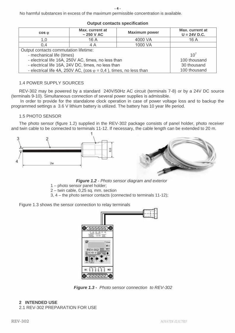
The photo sensor (figure 1.2) supplied in the REV-302 package consists of panel holder, photo receiver and twin cable to be connected to terminals 11-12. If necessary, the cable length can be extended to 20 m.
Figure 1.2 - Photo sensor diagram and exterior
1 – photo sensor panel holder; 2 – twin cable, 0,25 sq. mm. section 3, 4 – the photo sensor contacts (connected to terminals 11-12);
Figure 1.3 shows the sensor connection to relay terminals
Figure 1.3 - Photo sensor connection to REV-302 2 INTENDED USE 2.1 REV-302 PREPARATION FOR USE
- 5 -
NOVATEK-ELECTRO REV-302
2.1.1 Safety All connections must be performed on dead REV-302.
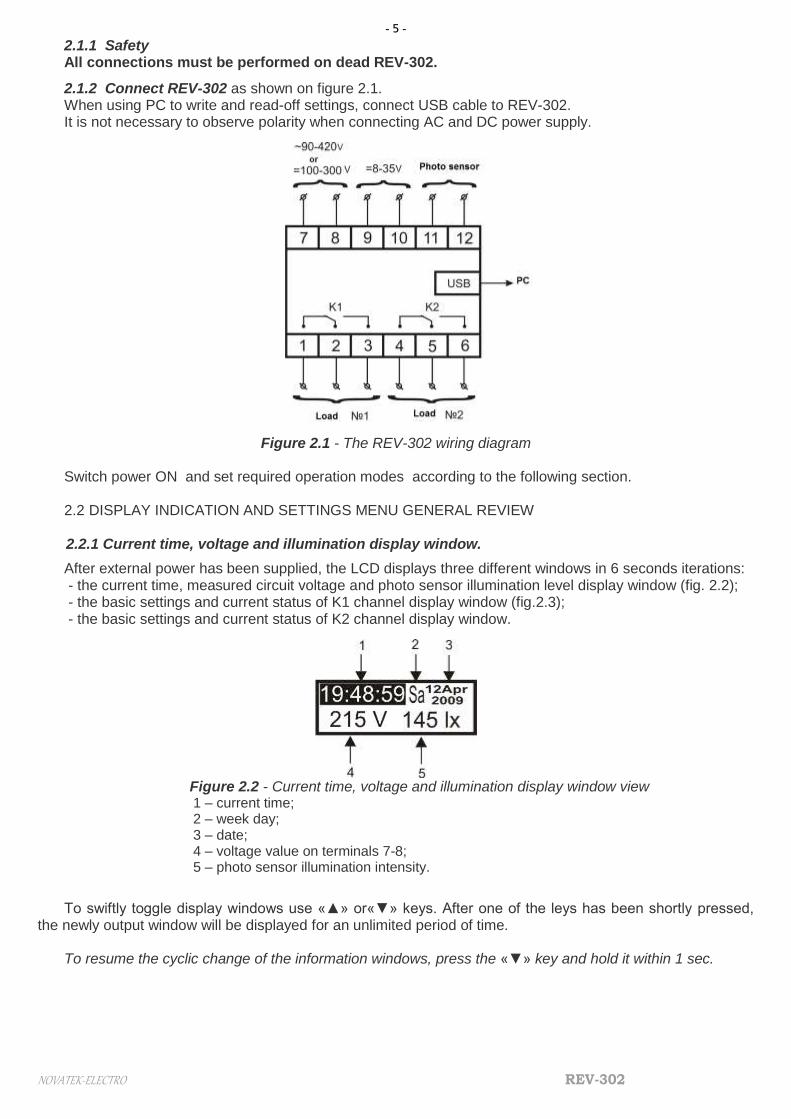
2.1.2 Connect REV-302 as shown on figure 2.1. When using PC to write and read-off settings, connect USB cable to REV-302. It is not necessary to observe polarity when connecting AC and DC power supply.
Figure 2.1 - The REV-302 wiring diagram
Switch power ON and set required operation modes according to the following section.
2.2 DISPLAY INDICATION AND SETTINGS MENU GENERAL REVIEW 2.2.1 Current time, voltage and illumination display window.
After external power has been supplied, the LCD displays three different windows in 6 seconds iterations: - the current time, measured circuit voltage and photo sensor illumination level display window (fig. 2.2); - the basic settings and current status of K1 channel display window (fig.2.3); - the basic settings and current status of K2 channel display window.
Figure 2.2 - Current time, voltage and illumination display window view 1 – current time; 2 – week day; 3 – date; 4 – voltage value on terminals 7-8; 5 – photo sensor illumination intensity.
To swiftly toggle display windows use «▲» or«▼» keys. After one of the leys has been shortly pressed,
the newly output window will be displayed for an unlimited period of time. To resume the cyclic change of the information windows, press the «▼» key and hold it within 1 sec.

- 6 -
REV-302 NOVATEK-ELECTRO
Figure 2.3 - One of the channels status window
1 – the corresponding channel current contacts position; 2 – the displayed channel; 3 – the channel control program (selected in the settings menu); 4 – active relay types for the channel (the relay which controls the contacts position at given moment); 5 – information about the current contacts position or about the upcoming event.
The upper half of the information window, besides the graphical view of the contacts position and the
controlling program number, also displays of the active relays types. For the time relay, more detailed information is supplied in a reduced format, where:
«Y-r» – yearly timer; «M-h» – monthly timer; «W-k» – weekly timer; «Day» – daily timer; «Pls» – pulse time relay; «Smp» – simple timer. If a timer is off, a dash line «----» is displayed in its position. For instance, Fig. 2.4. shows an example of a
display window for channel K1 controlled by P5 program with settings where the weekly time relay and voltage relay are switched on, but the photo relay is off:
Figure 2.4
The relay currently controlling the channel’s contacts is highlighted. Thus, on Fig. 2.3, it is the yearly timer, and on Fig. 2.4 – the weekly timer.
The bottom half of the display gives information either about the current status of the active relay, or about the upcoming event which will lead to the contacts commutation in accordance with the relay priority. The voltage relay has the highest priority; the time relay has the lowest priority. For the pulse timer and the simple timer relay, the time remaining till the event is indicated, for other types of time relays, the day and time of the next upcoming event occurrence are indicated (fig 2.3).If the photo sensor has detected the illumination intensity increase above the threshold level (and the voltage relay is either off or the circuit voltage is within set limits), then the display, accordingly, shows «L<Lthr» or «L>Lthr» with indication of the time left till the commutation moment. Similarly, if the if the voltage relay is on and the circuit voltage passes the threshold values of Umin or Umax, the display shows «U < Umin», «Unorm» or«U > Umax» with indication of the time left till the contacts open (fig. 2.4), if the voltage is not within normal limits, or till the control transfer to other type relays if the voltage has returned to within set limits.
2.2.2 Settings menu
To enter settings menu, press «Menu/OK» key. If the menu is password protected, the display screen will look as shown on figure 2.5.
Figure 2.5 - Password prompt
Use «◄» and «►» keys to select cursor position, and the «▲» and «▼» keys – to enter numbers. To confirm password press «Menu/OK».
The first settings menu looks as follows:

- 7 -
NOVATEK-ELECTRO REV-302
Figure 2.6 - Settings menu
1 – title of the root item in the menu; 2 – one of the menu items; 3 – menu item number within current group; 4 – total number of items within current group;
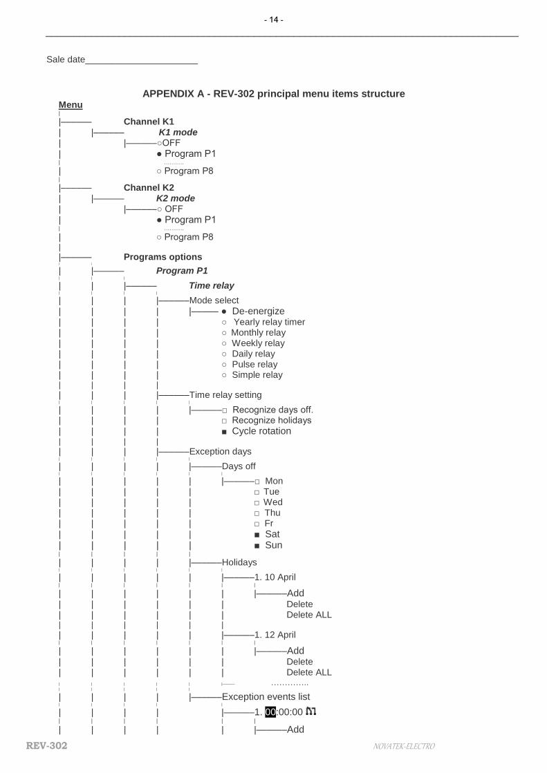
Use «▲» and «▼» keys to toggle the menu. To select the current menu item, press «►» key. To return to the previous menu item, press «◄» key. To exit the menu, press «◄» key several times in turn. 2.2.2.1 Structure of the principal menu elements in a tree view is presented in Appendix A. The upper
menu level contains the following items: ● K1 mode – allows selecting the controlling program number for К1 channel. ● K2 mode – the same for К2 channel. ● Programs options – the menu branch for setting the control program options, each containing Time
relay, Voltage relay, Photo relay items, that are covered in detail in the following chapter. ● Settings – allows setting common delay for the device startup after the external power supply:
● Time – current time of device setting. ● Date – editing of date. ● Year – editing of year. ● Summer time – ON/OFF the account of passing to daylight saving time in the last Sundays of
March and October. ● Delay – setting of general delay before the beginning of device work on the adjusted programs after
energising. ● Timer Precision – correction of device clock motion. It is necessary to specify, how seconds must be
compensated (to add or subtract) for the indicated number of twenty-four hours ● Voltage correction – let to correct of voltage which measuring on terminals 7-8. ● Illumination correction - let to correct of illumination which measuring by photo sensor
● Control – contains the items memory control and safety device: ● Clear memory – removes all events in all control programs lists. ● Device reset – resets all settings, both of the device and control programs to default values. The reset
does no change the password, the time settings and the event lists. ● Menu password – toggles on/off the menu entry password prompt ● New password – change current menu password.
● Information – contains the following items: ● Total number of events – events number created in all programs / as much as possible of events
number. ● Program version – current program version of device is represented.
2.3 USING REV-302
The REV-302 multifunctional relay has two channels: K1 and K2. Each of the Kx channels (where x is the channel number, 1 or 2) controls one electromagnetic relay with a group of switching terminals in accordance with one of the selected programs Px (where x is the program number: 1 to 8), the programs are configured separately or loaded from PC via USB port. Configuring a number of several programs in advance allows saving time for changing channel operation modes in the future.
Each Px program (and, accordingly, the channel Kx it controls) may be configured to operate either in three independent modes: time relay, voltage relay and photo-relay, or in four combined modes (time relay and voltage relay, time relay and photo-relay, voltage relay and photo-relay, time relay and voltage relay and photo-relay).
2.3.1 Time relay
To set up the time relay of one of the control programs Px, perform the following menu sequence: Menu ► Programs options ► Px program► Time relay. Here you can find the following menu items: ● Select mode – contains the following list of modes, one of which may include the time relay: ● Switch off – allows to completely switchg off time relay in the current control program with saving of all
settings and event lists. ● Yearly time relay – yearly event list execution mode.

- 8 -
REV-302 NOVATEK-ELECTRO
● Monthly time relay – monthly event list execution mode. ● Weekly time relay – weekly event list execution mode. ● Daily time relay – daily event list execution mode. ● Pulse time relay – the mode, where the relay contacts close and open at certain intervals after the
system energizing or the settings menu exit. ●Simple time relay – the mode, where the relay contacts close after a certain time interval after the
system energizing or the settings menu exit. ● Time relay settings – contains menu items that allow fine tuning the time relay:
● Observe days off – the setting refers only to calendar type timers (i.e. yearly, monthly, weekly, and daily), and for days off foresees an exceptional event list in place of the currently set list for the specified timer.
● Observe holidays – the setting refers only to calendar type timers, and for holidays (the holidays list is made up separately) foresees an exceptional event list in place of the currently set list for the specified timer.
● Cyclic rotation – indicates whether the mode event list will be executed once within a selected time interval, or will be repeated in cycles.
Please, see an example. Figure 2.7 presents a situation when P1 is set up as a daily timer in single-action mode (i.e. the checkmark in the “Cyclic rotation” setting is not checked) with five events, each of them successively closing and opening the contacts of the controlled K2 channel. The upper graph shows the planned events in the list of daily events, the lower graph indicates the channel contacts physical status. REV-302 was started at the moment t1=4:00, and as within the interval between t0 and t1 any load activating events are not present, the channel contacts will close when the time for event#1 comes (t2=8:00). The last event in the day is event #5 (t6= 22:00) which leaves the contacts closed until either power supply is turned off or a new program is loaded.
Figure 2.8 shows the same example, but the daily relay is in cyclic mode (i.e. the “Cyclic rotation” checkmark is checked). Unlike figure 2.7 at the moment of REV-302 start (t1=4:00) the time relay take into account the last status the contacts had to be in before power-off. As there are no events between t0 and t1, the time relay relies onto the last day event #5 (t6= 22:00), according to which the contacts close. From the beginning of the next day the sequence of events is repeated.
Figure 2.7 - Timer list single-action execution mode based on the daily timer example
P1
P1

- 9 -
NOVATEK-ELECTRO REV-302
Figure 2.8 - Timer list cyclic-action execution mode based on the daily timer example ●Exception days – contains menu items that allow choosing days off make holidays list and exception
events list, i.e. such events that will be executed on days off and holidays instead of the standard events list, if the corresponding items in the time relay settings have been selected (see previous paragraph):
● Days off – allows selecting days that will be considered days off. ● Holidays – contains the holiday list (empty by default) for the current control program. In order to add new
holiday to the list press «►» key and select “Add” item from the drop-down menu. Now the date and the month can be entered with use of the arrow keys. To exit the editor without saving changes, press «◄» key when in the leftmost item position (or just press «◄» key several times). To save the edited menu item, press « OK » key. After several list items have been created, they can be toggled with «▲» and «▼» keys. Total number of items in the list and the number of the displayed item are indicated in the upper right corner of the screen. A displayed list item can be deleted by selection of “Delete” item in the context menu. To clear all list , select “Delete ALL”.
Similar rules are valid for all editable lists of the device. ● List of exceptional events – contains list of events that will be executed only on days off and on
holidays. For every event it is necessary to specify the time and the contacts state, to which the controlled channel contacts will be transferred on the time specified.
● Yearly events (list) – current program year timer event list. It is executed if the corresponding program operation mode has been selected in the mode selection menu (see above).
● Monthly events (list) – the monthly timer event list. ● Weekly events (list) – the weekly timer event list. ● Daily events (list) – the daily timer event list.
2.3.1.1. Pulse time relay– contains the following pulse relay settings: ● Delay – indicates the time that assigns the pulse relay phase shift, within which the program-controlled
channel contacts will stay open after energizing or exiting the settings menu (before start of the cyclic operations execution).
● Contacts closed – time, for which the program-controlled channel contacts close after the preliminary delay (previous menu item) or the open contacts period (next menu item).
● Contacts open – time, for which the program-controlled channel contacts open after the closed contacts period (previous menu item).
2.3.1.2 Simple time relay – consists of one item only, where the delay is assigned, upon expiration of
which after the system energizing or the settings menu exit, the program-controlled channel contacts will be closed.
2.3.2 Voltage relay
The voltage relay within each Px program, if it is on, monitors the voltage on terminals 7-8. If the voltage falls below the Umin threshold or exceeds the Umax threshold, then, after the set time, the contacts of the Pх program controlled Кх channel will be opened regardless of the active time relay or the photo relay settings.
The control will be handed over to the time relay or the photo relay after the assigned restart time, upon return of the circuit voltage (U) to the range of
(Umin + dUmin) < U < (Umax – dUmax),
where dUmin and dUmax are the tolerance zones assigned (from 3 to 9 V) in the settings, which allow to remove false contact commutations in case of insignificant voltage fluctuations near the Umin and Umax thresholds.
ATTENTION! CONNECTION OF REV-302 TO THE COMPUTER BY MEANS OF CABLE USB, IN CERTAIN CASES, CAN BRING THE ADDITIONAL ERROR IN RESULTS OF VOLTAGE MEASUREMENT.
For normal operation of the block of the relay of tension the device has to be disconnected from the computer.
To set up the voltage relay of one of the control programs Px, perform the following menu sequence: Menu ► Programs options ► Px program► Voltage relay, which contains the following menu items: ● Mode – allows switching the voltage relay on or off within the current control program. ● Umin – sets up the bottom working range threshold with the dUmin positive tolerance zone. ● Umax – sets up the upper working range threshold with the dUmax negative tolerance zone. ● U < Umin – setting the time delay before the program controlled channel contacts are opened in case of
low circuit voltage. ● Unorm – setting of the time delay effective before the control over the program controlled channel
contacts is transferred to the time relay or the photo relay in case circuit voltage is restored to normal. ● U < Umin – setting the time delay before the program controlled channel contacts are opened in case of
high circuit voltage.
- 10 -
REV-302 NOVATEK-ELECTRO
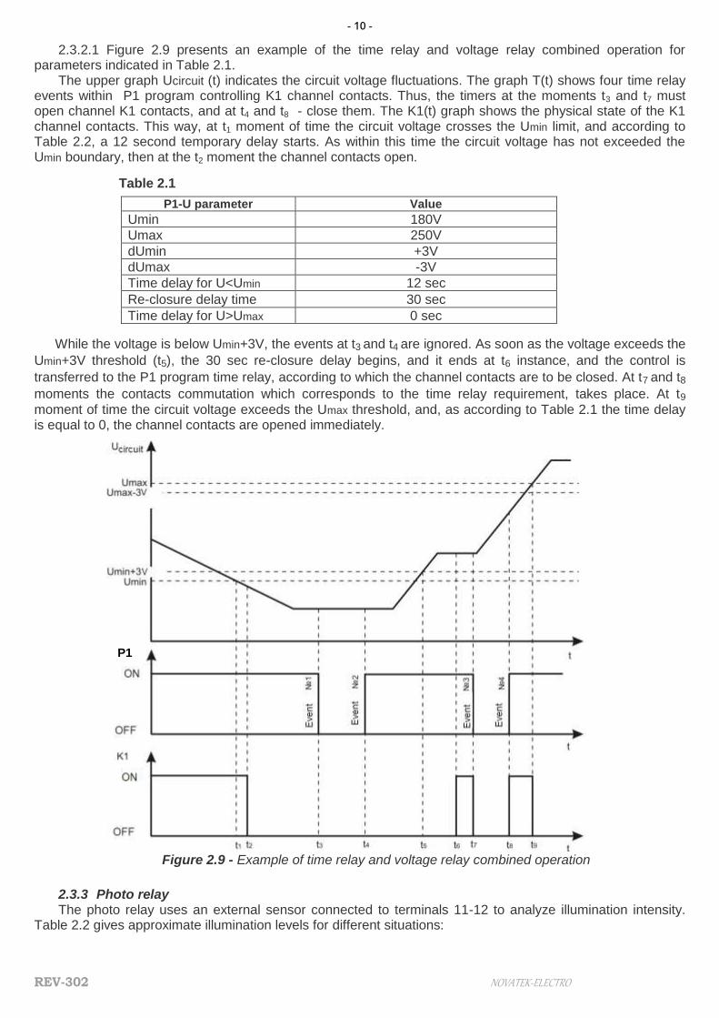
2.3.2.1 Figure 2.9 presents an example of the time relay and voltage relay combined operation for parameters indicated in Table 2.1.
The upper graph Ucircuit (t) indicates the circuit voltage fluctuations. The graph T(t) shows four time relay events within P1 program controlling K1 channel contacts. Thus, the timers at the moments t3 and t7 must open channel K1 contacts, and at t4 and t8 - close them. The K1(t) graph shows the physical state of the K1 channel contacts. This way, at t1 moment of time the circuit voltage crosses the Umin limit, and according to Table 2.2, a 12 second temporary delay starts. As within this time the circuit voltage has not exceeded the Umin boundary, then at the t2 moment the channel contacts open.
Table 2.1
P1-U parameter Value
Umin 180V
Umax 250V
dUmin +3V
dUmax -3V
Time delay for U<Umin 12 sec
Re-closure delay time 30 sec
Time delay for U>Umax 0 sec
While the voltage is below Umin+3V, the events at t3 and t4 are ignored. As soon as the voltage exceeds the
Umin+3V threshold (t5), the 30 sec re-closure delay begins, and it ends at t6 instance, and the control is
transferred to the P1 program time relay, according to which the channel contacts are to be closed. At t7 and t8
moments the contacts commutation which corresponds to the time relay requirement, takes place. At t9
moment of time the circuit voltage exceeds the Umax threshold, and, as according to Table 2.1 the time delay is equal to 0, the channel contacts are opened immediately.
Figure 2.9 - Example of time relay and voltage relay combined operation
2.3.3 Photo relay The photo relay uses an external sensor connected to terminals 11-12 to analyze illumination intensity.
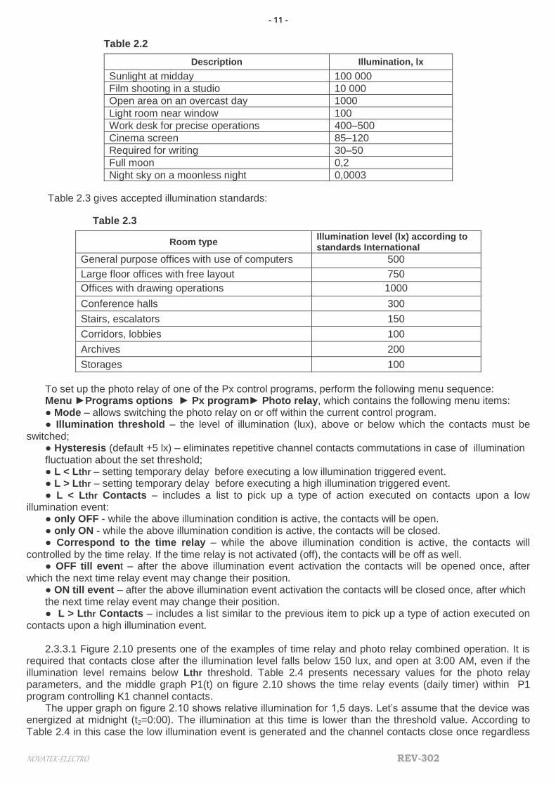
Table 2.2 gives approximate illumination levels for different situations:
P1
- 11 -
NOVATEK-ELECTRO REV-302
Table 2.2
Description Illumination, lx
Sunlight at midday 100 000
Film shooting in a studio 10 000
Open area on an overcast day 1000
Light room near window 100
Work desk for precise operations 400–500
Cinema screen 85–120
Required for writing 30–50
Full moon 0,2
Night sky on a moonless night 0,0003
Table 2.3 gives accepted illumination standards:
Table 2.3
Room type Illumination level (lx) according to standards International
General purpose offices with use of computers 500
Large floor offices with free layout 750
Offices with drawing operations 1000
Conference halls 300
Stairs, escalators 150
Corridors, lobbies 100
Archives 200
Storages 100
To set up the photo relay of one of the Px control programs, perform the following menu sequence: Menu ►Programs options ► Px program► Photo relay, which contains the following menu items: ● Mode – allows switching the photo relay on or off within the current control program. ● Illumination threshold – the level of illumination (lux), above or below which the contacts must be
switched; ● Hysteresis (default +5 lx) – eliminates repetitive channel contacts commutations in case of illumination fluctuation about the set threshold; ● L < Lthr – setting temporary delay before executing a low illumination triggered event. ● L > Lthr – setting temporary delay before executing a high illumination triggered event. ● L < Lthr Contacts – includes a list to pick up a type of action executed on contacts upon a low
illumination event: ● only OFF - while the above illumination condition is active, the contacts will be open. ● only ON - while the above illumination condition is active, the contacts will be closed. ● Correspond to the time relay – while the above illumination condition is active, the contacts will
controlled by the time relay. If the time relay is not activated (off), the contacts will be off as well. ● OFF till event – after the above illumination event activation the contacts will be opened once, after
which the next time relay event may change their position. ● ON till event – after the above illumination event activation the contacts will be closed once, after which the next time relay event may change their position. ● L > Lthr Contacts – includes a list similar to the previous item to pick up a type of action executed on
contacts upon a high illumination event. 2.3.3.1 Figure 2.10 presents one of the examples of time relay and photo relay combined operation. It is
required that contacts close after the illumination level falls below 150 lux, and open at 3:00 AM, even if the illumination level remains below Lthr threshold. Table 2.4 presents necessary values for the photo relay parameters, and the middle graph P1(t) on figure 2.10 shows the time relay events (daily timer) within P1 program controlling K1 channel contacts.
The upper graph on figure 2.10 shows relative illumination for 1,5 days. Let’s assume that the device was energized at midnight (t2=0:00). The illumination at this time is lower than the threshold value. According to Table 2.4 in this case the low illumination event is generated and the channel contacts close once regardless

- 12 -
REV-302 NOVATEK-ELECTRO
thr
P1
of the time relay current status, after which they transfer to waiting for the next event form the time relay or the photo relay. At the t1(3:00) time instance event #1 takes place, which transfers the contacts to the open position. At the t2 (3:30) time moment the illumination exceeds the threshold and the contacts control is handed over back to the photo relay, which according to the settings from Table 2.4 rigidly opens the contacts until the illumination falls below the threshold value. That is why when at the t3(17:00) time instance event #2 takes place, which must close the contacts, it does not happen. The contacts close once only when illumination falls below Lthr threshold at t4(18:26) time instance, after which the contacts may be closed either by a time relay event or by illumination surpassing the Lthr threshold, which actually takes place at t5(2:46).
Table 2.4
P1-F parameter Value
Illumination threshold 150 lux
Hysteresis +5 lux
Contacts state below the illumination threshold ON till event
Contacts state above the illumination threshold only OFF
Temp. delay below the illumination threshold 0 sec
Temp. delay above the illumination threshold 0 sec
Figure 2.10 - Example of time relay and photo relay combined operation 2.3.4 Software
Setting up REV-302 via special software brings the following advantages: - graphic representation of all device parameters; - quick toggling between parameters and possibility to edit them globally; - option of saving the device settings images to file on the PC hard drive, which allows creating different
device configurations and quickly load them when necessary, etc.; The latest software version can be downloaded from www.novatek-electro.com. website. To work with
the software use the dynamic prompt and explanations.
3 PACKAGE CONTENTS
REV-302 device……………………………………………………………………….1 pc. Photo sensor with connection cable…………………………………………………1 pc. CCP-USB2-AM5P-6 cable or similar……………………………………………….. 1 pc. Operating manual …………………………………………………………………… 1 pc. Packing………………………………………………………………………………… 1 pc.
- 13 -
NOVATEK-ELECTRO REV-302
4 MAINTENANCE 4.1 SAFETY
During maintenance operations, REV-302 power supply must be disconnected. The unit is not intended for operation under vibrations or shocks. Do not allow any water on the contacts of the connecting blocks or inner elements of the unit. Do not use the unit in corrosive environments with the air containing acids, alkalis, oils, etc. 4.2 MAINTENANCE SCHEDULE Recommended maintenance schedule – semiannually. Maintenance scheduled operations consist of visual observation, during which wiring connection to
REV-302 terminals is checked, casing integrity check for cracking and chipping.
5 PERIOD OF SERVICE AND STORAGE, AND MANUFACTURER’S WARRANTY 5.1 Service life is 10 years. Refer to the manufacturer upon the expire of the service life. 5.2 Warranty period is 36 month upon the day of sale. The manufacturer shall repair the unit, in the compliance with the operating manual by the user, within the warranty
period.
REV-302 is not subject to the warranty service in the following cases: expiry of the warranty period; availability of mechanical damages; attempts to open and repair ; traces of moisture attack or in the presence
of foreign items inside the unit. 5.3 Warranty service is provided in the place of purchase. 5.4 The manufacturer's warranty does not cover compensation for direct or indirect losses associated with the
unit transportation to the place of purchase or manufacturer’s plant. 5.5 Post-warranty service shall be provided by the manufacturer.
6 TRANSPORTATION Transportation of REV-302 in package may be effected by any type of transport according to the
transportation rules and regulations valid for such mode transportation. During transportation, shipping and storing in a warehouse REV-302 must be protected form blows,
shocks and moisture.
- 14 -
REV-302 NOVATEK-ELECTRO
____________________________________________________________________________________
Sale date______________________
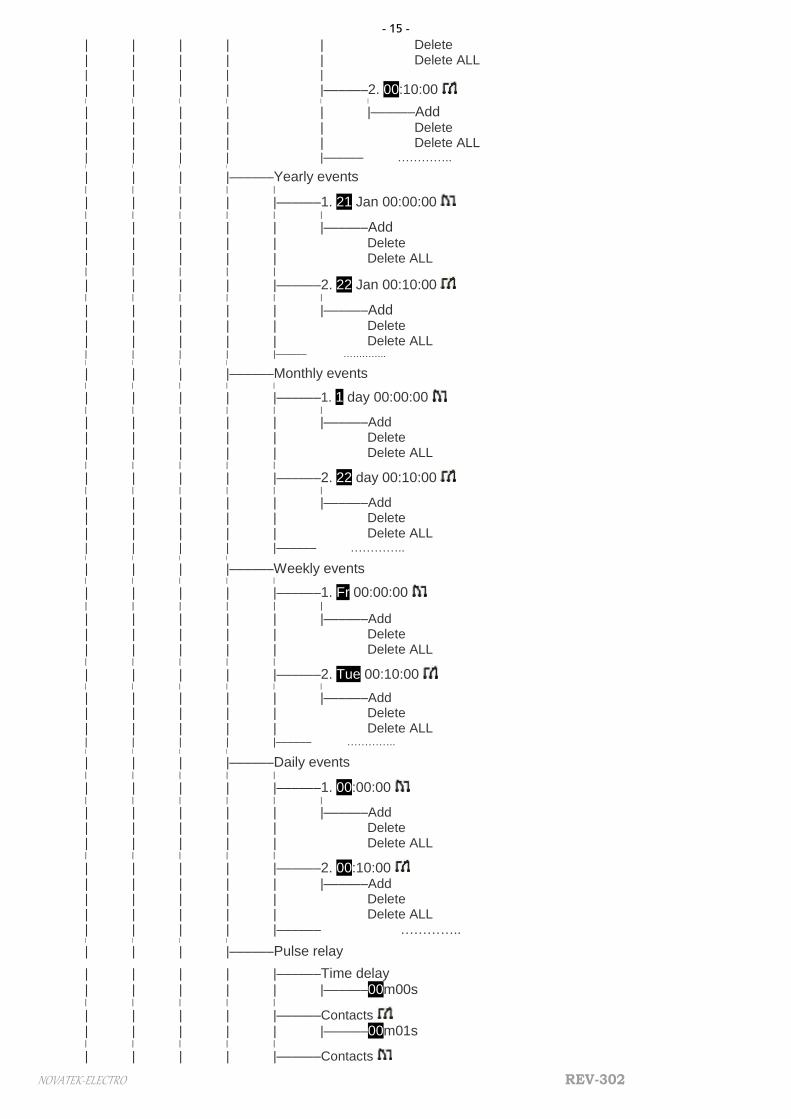
APPENDIX A - REV-302 principal menu items structure Menu |
|–––––– Channel K1 | |–––––– K1 mode | |––––––○OFF
| ● Program P1 | ………..
| ○ Program P8 |
|–––––– Channel K2 | |–––––– K2 mode | |––––––○ OFF
| ● Program P1 | ………..
| ○ Program P8 |
|–––––– Programs options | |
| |–––––– Program P1 | | |
| | |–––––– Time relay | | | |
| | | |––––––Mode select
| | | | |––––– ● De-energize | | | | ○ Yearly relay timer | | | | ○ Monthly relay | | | | ○ Weekly relay | | | | ○ Daily relay | | | | ○ Pulse relay | | | | ○ Simple relay | | | |
| | | |––––––Time relay setting | | | | |
| | | | |––––––□ Recognize days off. | | | | □ Recognize holidays
| | | | ■ Cycle rotation | | | |
| | | |––––––Exception days | | | | |
| | | | |––––––Days off | | | | | |
| | | | | |––––––□ Mon | | | | | □ Tue | | | | | □ Wed | | | | | □ Thu | | | | | □ Fr
| | | | | ■ Sat | | | | | ■ Sun | | | | |
| | | | |––––––Holidays | | | | | |
| | | | | |––––––1. 10 April | | | | | | |
| | | | | | |––––––Add
| | | | | | Delete | | | | | | Delete ALL | | | | | |
| | | | | |––––––1. 12 April | | | | | | |
| | | | | | |––––––Add
| | | | | | Delete | | | | | | Delete ALL | | | | | |–––––– …………..
| | | | |
| | | | |––––––Exception events list | | | | |
| | | | |––––––1. 00:00:00 | | | | | |
| | | | | |––––––Add
- 15 -
NOVATEK-ELECTRO REV-302
| | | | | Delete | | | | | Delete ALL | | | | |
| | | | |––––––2. 00:10:00 | | | | | |
| | | | | |––––––Add | | | | | Delete | | | | | Delete ALL | | | | |–––––– ………….. | | | |
| | | |––––––Yearly events | | | | |
| | | | |––––––1. 21 Jan 00:00:00 | | | | | |
| | | | | |––––––Add
| | | | | Delete | | | | | Delete ALL | | | | |
| | | | |––––––2. 22 Jan 00:10:00 | | | | | |
| | | | | |––––––Add | | | | | Delete | | | | | Delete ALL | | | | |–––––– ………….. | | | |
| | | |––––––Monthly events | | | | |
| | | | |––––––1. 1 day 00:00:00 | | | | | |
| | | | | |––––––Add | | | | | Delete | | | | | Delete ALL | | | | |
| | | | |––––––2. 22 day 00:10:00 | | | | | |
| | | | | |––––––Add | | | | | Delete | | | | | Delete ALL | | | | |–––––– ………….. | | | |
| | | |––––––Weekly events | | | | |
| | | | |––––––1. Fr 00:00:00 | | | | | |
| | | | | |––––––Add | | | | | Delete | | | | | Delete ALL | | | | |
| | | | |––––––2. Tue 00:10:00 | | | | | |
| | | | | |––––––Add | | | | | Delete | | | | | Delete ALL | | | | |–––––– ………….. | | | |
| | | |––––––Daily events | | | | |
| | | | |––––––1. 00:00:00 | | | | | |
| | | | | |––––––Add | | | | | Delete | | | | | Delete ALL | | | | |
| | | | |––––––2. 00:10:00 | | | | | |––––––Add | | | | | Delete | | | | | Delete ALL | | | | |–––––– ………….. | | | |
| | | |––––––Pulse relay
| | | | |––––––Time delay | | | | | |––––––00m00s | | | | |
| | | | |––––––Contacts
| | | | | |––––––00m01s | | | | |
| | | | |––––––Contacts
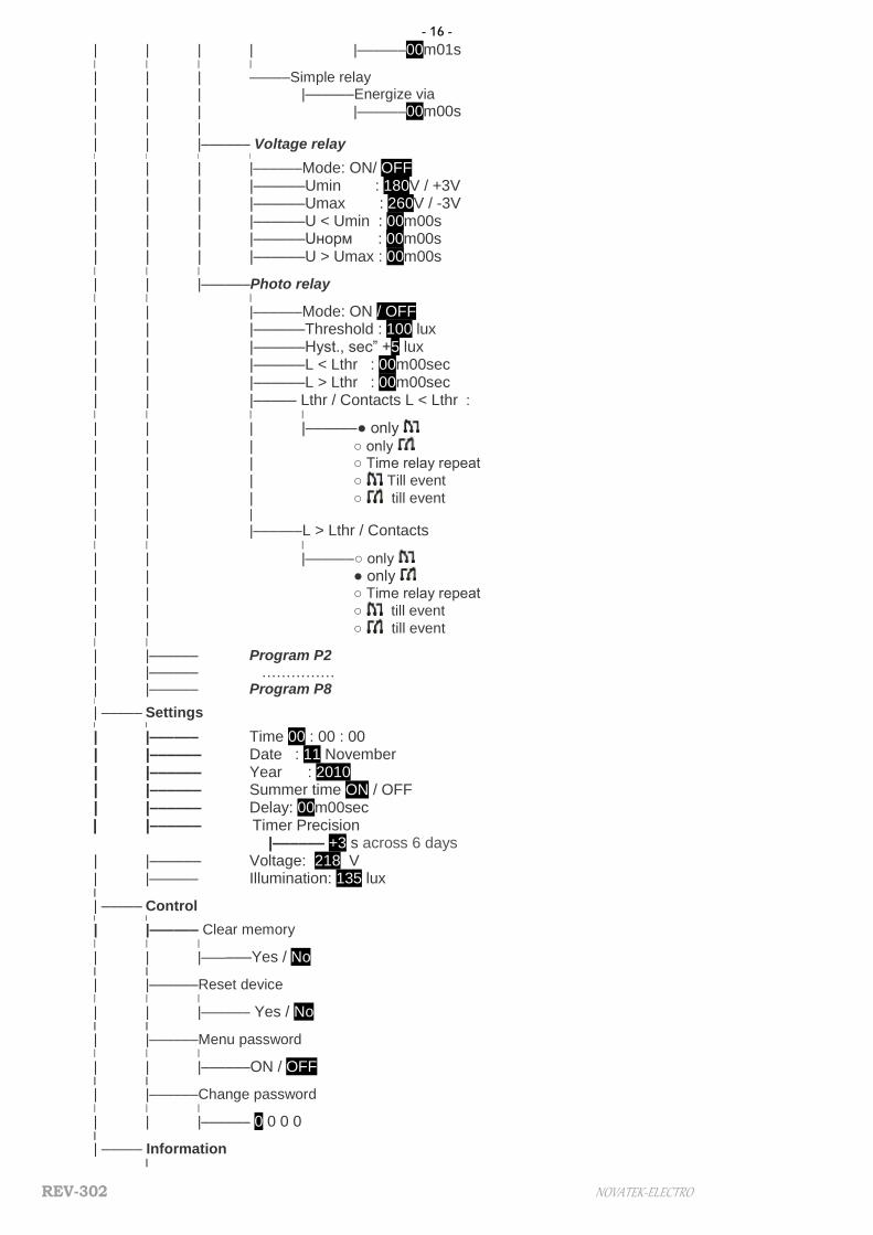
- 16 -
REV-302 NOVATEK-ELECTRO
| | | | |––––––00m01s | | | |
| | | –––––Simple relay | | | |––––––Energize via
| | | |––––––00m00s | | |
| | |–––––– Voltage relay | | | |
| | | |––––––Mode: ON/ OFF | | | |––––––Umin : 180V / +3V | | | |––––––Umax : 260V / -3V | | | |––––––U < Umin : 00m00s | | | |––––––Uнорм : 00m00s | | | |––––––U > Umax : 00m00s | | |
| | |––––––Photo relay | | |
| | |––––––Mode: ON / OFF | | |––––––Threshold : 100 lux | | |––––––Hyst., sec” +5 lux | | |––––––L < Lthr : 00m00sec | | |––––––L > Lthr : 00m00sec | | |––––– Lthr / Contacts L < Lthr : | | | |
| | | |––––––● only
| | | ○ only | | | ○ Time relay repeat
| | | ○ Till event
| | | ○ till event | | |
| | |––––––L > Lthr / Contacts | | |
| | |––––––○ only
| | ● only | | ○ Time relay repeat
| | ○ till event
| | ○ till event | |
| |–––––– Program P2 | |–––––– …………… | |–––––– Program P8
|
| ––––– Settings | |
| |–––––– Time 00 : 00 : 00 | |–––––– Date : 11 November | |–––––– Year : 2010 | |–––––– Summer time ON / OFF | |–––––– Delay: 00m00sec | |–––––– Timer Precision |–––––– +3 s across 6 days | |–––––– Voltage: 218 V | |–––––– Illumination: 135 lux |
| ––––– Control | |
| |–––––– Clear memory | | |
| | |––––––Yes / No | |
| |––––––Reset device | | |
| | |–––––– Yes / No | |
| |––––––Menu password | | |
| | |––––––ON / OFF | |
| |––––––Change password | | |
| | |–––––– 0 0 0 0 |
| ––––– Information |

- 17 -
NOVATEK-ELECTRO REV-302
|––––––events of 0/5000 |
|––––––Program version v1.2