multimedia broadcast-multi cast service pd
TRANSCRIPT

RAN
MBMS Parameter Description
Issue 01
Date 2009-03-30
Huawei Technologies Co., Ltd. provides customers with comprehensive technical support and service. For
Huawei Proprietary and Confidential Copyright © Huawei Technologies Co.,
Ltd

any assistance, please contact our local office or company headquarters.
Huawei Technologies Co., Ltd.
Address: Huawei Industrial Base
Bantian, Longgang
Shenzhen 518129
People's Republic of China
Website: http://www.huawei.com
Email: [email protected]
Copyright © Huawei Technologies Co., Ltd. 2009. All rights reserved.
No part of this document may be reproduced or transmitted in any form or by any means without prior written consent of Huawei Technologies Co., Ltd.
Trademarks and Permissions
and other Huawei trademarks are trademarks of Huawei Technologies Co., Ltd.
All other trademarks and trade names mentioned in this document are the property of their respective holders.
Notice
The information in this document is subject to change without notice. Every effort has been made in the preparation of this document to ensure accuracy of the contents, but all statements, information, and recommendations in this document do not constitute the warranty of any kind, express or implied.
Huawei Proprietary and Confidential Copyright © Huawei Technologies Co.,
Ltd

RANMBMS Parameter Description
About This Document
About This Document
Author
Prepared by Wang Hongwei Date 2008-10-22
Edited by Cheng Xiaoli Date 2008-12-09
Reviewed by - -
Translated by Ye Qinyan Date 2008-12-20
Tested by Han Zhe Date 2009-01-10
Approved by Duan Zhongyi Date 2009-03-30
Issue 01 (2009-03-30) Huawei Proprietary and Confidential Copyright © Huawei Technologies Co.,
Ltd
iii

RANMBMS Parameter Description
Contents
Contents
1 Change History...........................................................................1-3
2 Introduction to MBMS.................................................................2-3
3 MBMS Principles.........................................................................3-33.1 MBMS Architecture and Operation Overview...............................................................................................3-3
3.1.1 MBMS Architecture..............................................................................................................................3-3
3.1.2 MBMS Operating Modes......................................................................................................................3-3
3.1.3 MBMS Data Transfer Modes................................................................................................................3-3
3.1.4 MBMS User Service Types...................................................................................................................3-3
3.2 MBMS Channel Structures.............................................................................................................................3-3
3.2.1 MBMS Logical Channels......................................................................................................................3-3
3.2.2 MBMS Transport Channels...................................................................................................................3-3
3.2.3 MBMS Physical Channels....................................................................................................................3-3
3.3 Basic MBMS Service Provision Process........................................................................................................3-3
3.3.1 Overview of MBMS Service Provision Process...................................................................................3-3
3.3.2 MBMS Session Start Procedure............................................................................................................3-3
3.3.3 MBMS Notification...............................................................................................................................3-3
3.3.4 MBMS Session Stop Procedure............................................................................................................3-3
3.4 MBMS Key Functions....................................................................................................................................3-3
3.4.1 MBMS UTRAN Signaling Flows.........................................................................................................3-3
3.4.2 Selective and Soft Combining...............................................................................................................3-3
3.4.3 Frequency Layer Convergence and Dispersion....................................................................................3-3
3.4.4 Iub Transmission Optimization.............................................................................................................3-3
3.4.5 Counting Procedure...............................................................................................................................3-3
3.4.6 MBMS Over Iur....................................................................................................................................3-3
4 MBMS RRM Algorithms................................................................4-34.1 MBMS Transfer Mode Selection....................................................................................................................4-3
4.1.1 Static PtM Mode....................................................................................................................................4-3
4.1.2 Static PtP Mode.....................................................................................................................................4-3
4.1.3 Enhanced PtM Mode.............................................................................................................................4-3
4.1.4 Dynamic PtP/PtM Mode.......................................................................................................................4-3
4.2 MBMS Dynamic Power Setting in PtM Mode...............................................................................................4-3
4.3 MBMS Admission Control.............................................................................................................................4-3
Issue 01 (2009-03-30) Huawei Proprietary and Confidential Copyright © Huawei Technologies Co.,
Ltd
v

RANMBMS Parameter Description
Contents
4.3.1 Power Admission...................................................................................................................................4-3
4.3.2 Code Admission....................................................................................................................................4-3
4.3.3 Iub and Credit Admission......................................................................................................................4-3
4.4 MBMS Pre-emption Control..........................................................................................................................4-3
5 Impact of MBMS on Other Features..............................................5-35.1 Impact of MBMS on Admission and Pre-emption Control............................................................................5-3
5.2 MBMS Related Actions in LDR.....................................................................................................................5-3
5.3 MBMS Related Actions in OLC.....................................................................................................................5-3
6 MBMS Parameters.......................................................................6-36.1 Description.....................................................................................................................................................6-3
6.2 Values and Ranges..........................................................................................................................................6-3
7 Reference Documents.................................................................7-3
Issue 01 (2009-03-30) Huawei Proprietary and Confidential Copyright © Huawei Technologies Co.,
Ltd
vi

RANMBMS Parameter Description
Error! Use the Home tab to apply 标题 1 to the text that you want to appear here.Error! Use the Home
tab to apply 标题 1 to the text that you want to appear here.
1 Change History
The change history provides information on the changes in different document versions.
Document and Product Versions
Document Version RAN Version
01 (2009-03-30) 11.0
Draft (2009-03-10) 11.0
Draft (2009-01-15) 11.0
This document is based on the BSC6810 and 3900 series NodeBs.
The available time of each feature is subject to the RAN product roadmap.
There are two types of changes, which are defined as follows:
Feature change: refers to the change in the MBMS feature.
Editorial change: refers to the change in the information that was inappropriately described or the addition of the information that was not described in the earlier version.
01 (2009-03-30)
This is the document for the first commercial release of RAN11.0.
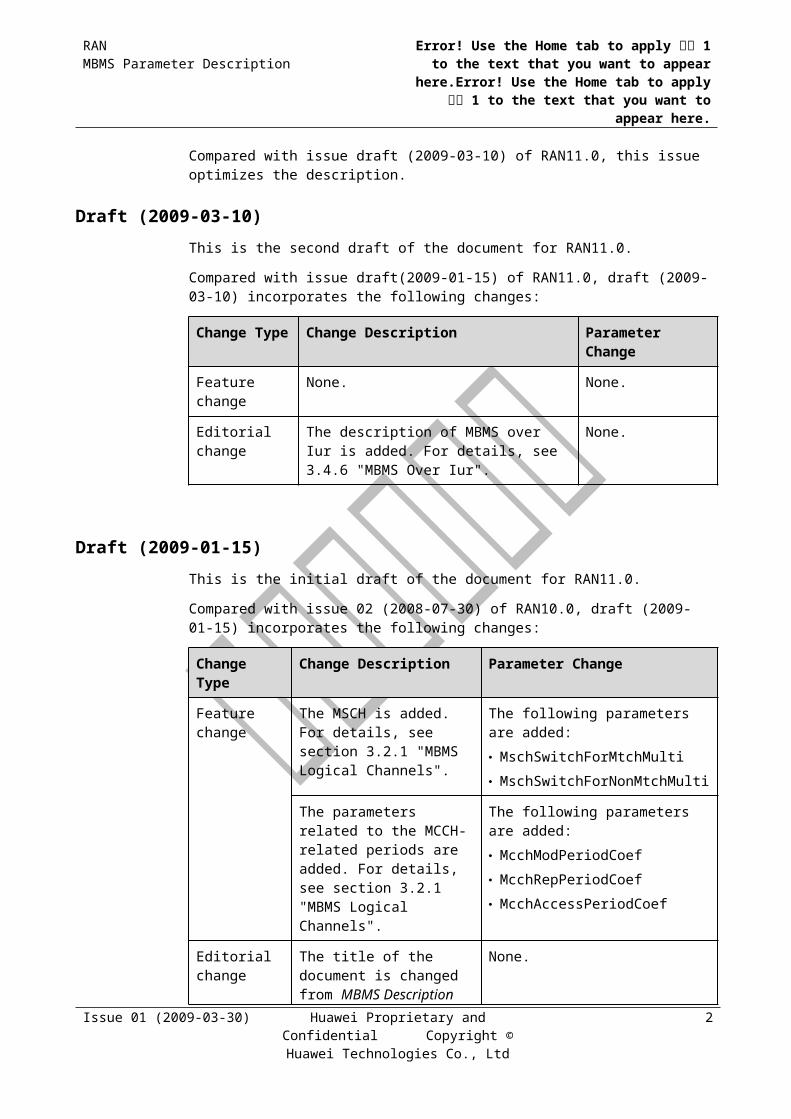
Compared with issue draft (2009-03-10) of RAN11.0, this issue optimizes the description.
Draft (2009-03-10)
This is the second draft of the document for RAN11.0.
Compared with issue draft(2009-01-15) of RAN11.0, draft (2009-03-10) incorporates the following changes:
Issue 01 (2009-03-30) Huawei Proprietary and Confidential Copyright © Huawei Technologies Co.,
Ltd
1
RANMBMS Parameter Description
Error! Use the Home tab to apply 标题 1 to the text that you want to appear here.Error! Use the Home
tab to apply 标题 1 to the text that you want to appear here.
Change Type
Change Description Parameter Change
Feature change None. None.
Editorial change The description of MBMS over Iur is added. For details, see 3.4.6 "MBMS Over Iur".
None.
Draft (2009-01-15)
This is the initial draft of the document for RAN11.0.
Compared with issue 02 (2008-07-30) of RAN10.0, draft (2009-01-15) incorporates the following changes:
Change Type
Change Description Parameter Change
Feature change The MSCH is added. For details, see section 3.2.1 "MBMS Logical Channels".
The following parameters are added: MschSwitchForMtchMulti MschSwitchForNonMtchMulti
The parameters related to the MCCH-related periods are added. For details, see section 3.2.1 "MBMS Logical Channels".
The following parameters are added: McchModPeriodCoef McchRepPeriodCoef McchAccessPeriodCoef
Editorial change
The title of the document is changed from MBMS Description to MBMS Parameter Description.
Parameter names are replaced with parameter IDs.
None.
Issue 01 (2009-03-30) Huawei Proprietary and Confidential Copyright © Huawei Technologies Co.,
Ltd
2

RANMBMS Parameter Description
Error! Use the Home tab to apply 标题 1 to the text that you want to appear here.Error! Use the Home
tab to apply 标题 1 to the text that you want to appear here.
2 Introduction to MBMS
The Multimedia Broadcast Multicast Service (MBMS) feature provides unidirectional point-to-multipoint multimedia services. It allows data to be transmitted from one source to multiple destinations.
In traditional mobile networks, the Cell Broadcast Service (CBS), known as a type of message service, enables the transmission of a small amount of low-bit-rate data to all the UEs in the cell. With the rapid development of the Internet, services that feature a large data volume, long duration, and high delay sensitivity are emerging.
For better utilization of the mobile network resources, the 3GPP protocol standardizes the MBMS feature. With the MBMS, a mobile network can provide point-to-multipoint services from one data source to multiple UEs. The MBMS aims to share network resources and improve network resource utilization, especially the utilization of resources on the Uu interface. The MBMS specified in the 3GPP R6 allows both low-bit-rate text messages and high-speed multimedia services to be transmitted in the form of broadcast or multicast, which identifies trend of mobile data in the future.
According to 3GPP, MBMS supports services of two operating modes: broadcast and multicast. Huawei product supports only broadcast and enhanced broadcast.
The Type of Service of MBMS includes streaming service and background service.
Intended Audience
This document is intended for:
System operators who need a general understanding of MBMS.
Personnel working on Huawei products or systems.
Impact Impact on system performance
To support MBMS, specific channels must be set up in the cell, which will consume part of the power, code, credit, and transmission resources.
Impact on other features
The MBMS may impact on load control. For detailed information about the impact of MBMS on the other features, see chapter 5 "Impact of MBMS on Other Features".
Issue 01 (2009-03-30) Huawei Proprietary and Confidential Copyright © Huawei Technologies Co.,
Ltd
1

RANMBMS Parameter Description
Error! Use the Home tab to apply 标题 1 to the text that you want to appear here.Error! Use the Home
tab to apply 标题 1 to the text that you want to appear here.
Network Elements Involved
Table 2-1 lists the Network Elements (NEs) involved in the MBMS feature.
Table 2-1 NEs involved in the MBMS feature
UE NodeB RNC MSC Server
MGW SGSN GGSN BM-SC
HLR
√ √ √ – – √ √ √ –
NOTE – : not involved √: involved
UE = User Equipment, RNC = Radio Network Controller, MSC Server = Mobile Service Switching Center Server, MGW = Media Gateway, SGSN = Serving GPRS Support Node, GGSN = Gateway GPRS Support Node, BM-SC = Broadcast Multicast Service Centre, HLR = Home Location Register
Issue 01 (2009-03-30) Huawei Proprietary and Confidential Copyright © Huawei Technologies Co.,
Ltd
2

RANMBMS Parameter Description
Error! Use the Home tab to apply 标题 1 to the text that you want to appear here.Error! Use the Home
tab to apply 标题 1 to the text that you want to appear here.
3 MBMS Principles
This chapter has the following contents:
MBMS Architecture and Operation Overview
MBMS Channel Structures
Basic MBMS Service Provision Process
MBMS Key Function
3.1 MBMS Architecture and Operation Overview
This section describes the architecture, operating modes, data transfer modes, and user service types of the MBMS.
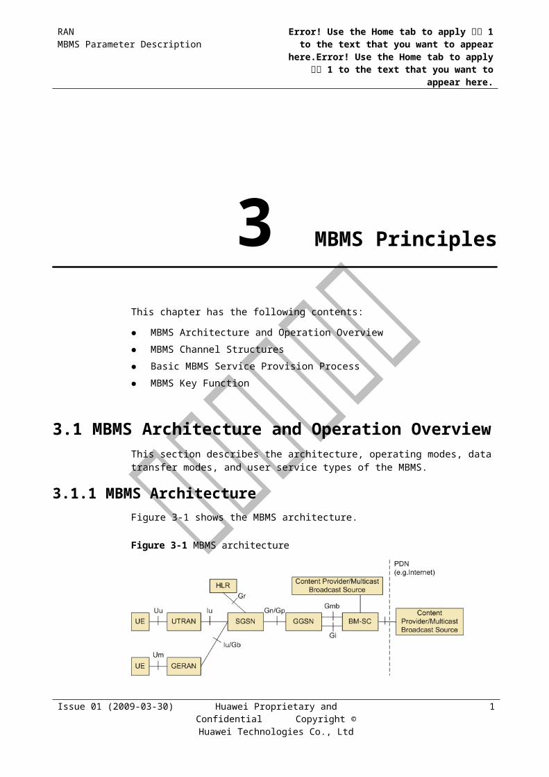
3.1.1 MBMS ArchitectureFigure 3-1 shows the MBMS architecture.
Figure 3-1 MBMS architecture
The MBMS helps to utilize the resources in the Radio Access Network (RAN) and the Core Network (CN), especially on the Uu interface.
Issue 01 (2009-03-30) Huawei Proprietary and Confidential Copyright © Huawei Technologies Co.,
Ltd
1
RANMBMS Parameter Description
Error! Use the Home tab to apply 标题 1 to the text that you want to appear here.Error! Use the Home
tab to apply 标题 1 to the text that you want to appear here.
To implement the MBMS, new features are introduced to both the existing 3GPP-compliant NEs and the added NEs. The added NEs such as Broadcast Multicast Service Center (BM-SC) provide functions related to the MBMS user management.
The functions of the UE and of the existing NEs such as GGSN, SGSN, and UTRAN are expanded to support the MBMS.
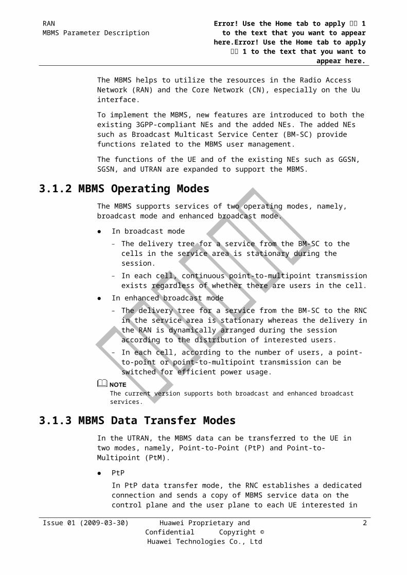
3.1.2 MBMS Operating ModesThe MBMS supports services of two operating modes, namely, broadcast mode and enhanced broadcast mode.
In broadcast mode
− The delivery tree for a service from the BM-SC to the cells in the service area is stationary during the session.
− In each cell, continuous point-to-multipoint transmission exists regardless of whether there are users in the cell.
In enhanced broadcast mode
− The delivery tree for a service from the BM-SC to the RNC in the service area is stationary whereas the delivery in the RAN is dynamically arranged during the session according to the distribution of interested users.
− In each cell, according to the number of users, a point-to-point or point-to-multipoint transmission can be switched for efficient power usage.
The current version supports both broadcast and enhanced broadcast services.
3.1.3 MBMS Data Transfer ModesIn the UTRAN, the MBMS data can be transferred to the UE in two modes, namely, Point-to-Point (PtP) and Point-to-Multipoint (PtM).
PtP
In PtP data transfer mode, the RNC establishes a dedicated connection and sends a copy of MBMS service data on the control plane and the user plane to each UE interested in the service. The PtP data transfer mode applies only to the enhanced broadcast mode.
PtM
In PtM data transfer mode, the MBMS service data on the control plane and the user plane is transferred on common channels. UEs interested in the service in a cell share the same copy of data. The PtM data transfer mode applies to the broadcast and enhanced broadcast modes.
For an MBMS service, the transfer mode can be different in different cells.
3.1.4 MBMS User Service TypesThe MBMS user services are of the following types:
Streaming service
The streaming service carries continuous data flow for streaming media (audio and video).
Background service
Issue 01 (2009-03-30) Huawei Proprietary and Confidential Copyright © Huawei Technologies Co.,
Ltd
2
RANMBMS Parameter Description
Error! Use the Home tab to apply 标题 1 to the text that you want to appear here.Error! Use the Home
tab to apply 标题 1 to the text that you want to appear here.
The background service carries binary data or files on MBMS channels. Background services require high reliability, that is, all data must be correctly received.
The type of the service carried by the corresponding MBMS channel can be set through the ServiceType parameter.
3.2 MBMS Channel StructuresThis section describes the logical channels, transport channels, and physical channels related to the MBMS feature.
3.2.1 MBMS Logical ChannelsDifferent channels are used as MBMS logical channels depending on the specific transfer mode.
In PtP mode, DCCH and DTCH are used to carry MBMS control plane and user plane information, respectively.
In PtM mode, several new MBMS specific logical channels are introduced to carry MBMS control plane and user plane information, including the MBMS point-to-multipoint Control Channel (MCCH) and MBMS point-to-multipoint Traffic Channel (MTCH).
MCCHThe MCCH transfers the downlink point-to-multipoint control plane data between the network and the UE in idle mode or the RRC connected mode. In each cell enabled with MBMS, only one MCCH exists. The MCCH is mapped to the FACH in the SCCPCH as indicated in System Information Block Type 5/Type 6 on the BCCH. In Huawei RAN11.0, the MCCH occupies a dedicated SCCPCH, that is, MCCH cannot be multiplexed with other logical channels on the same SCCPCH.
The following types of information are transmitted on the MCCH:
MBMS access information
MBMS general information
MBMS modified service information
MBMS unmodified service information
MBMS common PtM RB information
MBMS current cell PtM RB information
MBMS neighboring cell PtM RB information
The MCCH transmission has the following characteristics:
The MCCH information other than the MBMS access information is periodically sent according to the repetition period. The repetition period is specified by the McchRepPeriodCoef parameter.
The MCCH information other than the MBMS access information remains unchanged in a modification period and is repeated for a modification period. A modification period contains many repetition periods. The modification period is specified by the
Issue 01 (2009-03-30) Huawei Proprietary and Confidential Copyright © Huawei Technologies Co.,
Ltd
3

RANMBMS Parameter Description
Error! Use the Home tab to apply 标题 1 to the text that you want to appear here.Error! Use the Home
tab to apply 标题 1 to the text that you want to appear here.
McchModPeriodCoef parameter. The MCCH information other than the MBMS access information can change only at the start of a modification period.
The access information period is specified by the McchAccessPeriodCoef parameter. The transmissions of the MBMS access information message within a modification period need not have the same content.
Figure 3-1shows the relations among the MCCH information periods. The colors in Figure 3-2 denote different MCCH information.
Figure 3-1 Relations among the MCCH information periods
MTCHThe MTCH transfers the downlink point-to-multipoint user plane data between the network and the UE in idle mode or RRC connected mode. The MTCH is mapped to the FACH in the SCCPCH indicated by the MCCH.
In Huawei RAN11.0, a maximum of four MTCHs can be mapped onto one FACH; only one FACH can be mapped onto one SCCPCH carrying the MTCH. The FACH and SCCPCH carrying the MTCH cannot be shared by other types of logical channels.
MSCHThe MBMS point-to-multipoint Scheduling Channel (MSCH) transfers the downlink point-to-multipoint service transmission scheduling data between the RAN and the UE. By referring to the scheduling data on the MSCH, the UE need not receive the data continuously on the MTCH, thus saving the power of the UE. The MSCH is mapped onto the SCCPCH carrying the MTCH; only one MSCH can be mapped onto each SCCPCH carrying the MTCH.
Issue 01 (2009-03-30) Huawei Proprietary and Confidential Copyright © Huawei Technologies Co.,
Ltd
4

RANMBMS Parameter Description
Error! Use the Home tab to apply 标题 1 to the text that you want to appear here.Error! Use the Home
tab to apply 标题 1 to the text that you want to appear here.
Figure 3-1 Relations between the MSCH scheduling information and MTCH data blocks
The scheduling information is sent on the MSCH periodically according to the scheduling period. The start time of the scheduling period is called scheduling time. The MSCH sends the scheduling message to the UE at each scheduling time to indicate the data transmission (start time and duration) on the MTCH that is multiplexed onto the same SCCPCH as the MSCH during the next scheduling period. In this way, the UE needs to receive the data only when the corresponding MTCH starts to send data. At other times, the UE does not need to monitor the MTCH, thus saving the power of the UE.
When multiple MTCHs are multiplexed onto the same SCCPCH, using the MSCH helps to save the power. When only one MTCH is carried on the SCCPCH, using the MSCH helps to save the power only if the data on the MTCH is discontinuous (for example, during downloading); otherwise, the using of the MSCH is a waste of resources.
In Huawei RAN11.0, the following parameters are provided to determine whether the MSCH is used:
MschSwitchForMtchMulti is provided to determine whether the MSCH is used for the SCCPCH that carries the MTCH.
MschSwitchForNonMtchMulti is provided to determine whether the MSCH is used for the SCCPCH that does not carry the MTCH.
3.2.2 MBMS Transport ChannelsDifferent channels are used as MBMS transport channels depending on the specific transfer mode.
In PtP mode, DCCH and DTCH are mapped onto DCH or HS-DSCH. The criterion for choosing DCH or HS-DSCH as their bearer is the same as the criterion for choosing DCH or HS-DSCH as the bearer for other services. For detailed information, see the Radio Bearers Parameter Description.
In PtM mode, the MCCH and MTCH are mapped onto FACH.
Issue 01 (2009-03-30) Huawei Proprietary and Confidential Copyright © Huawei Technologies Co.,
Ltd
5

RANMBMS Parameter Description
Error! Use the Home tab to apply 标题 1 to the text that you want to appear here.Error! Use the Home
tab to apply 标题 1 to the text that you want to appear here.
3.2.3 MBMS Physical ChannelsDifferent channels are used as MBMS physical channels depending on the specific transfer mode.
In PtP mode, DPCH or HS-PDSCH is used as the MBMS physical channel.
In PtM mode, SCCPCH is used as the MBMS physical channel.
In addition, a new physical channel, namely the MBMS Notification Indicator Channel (MICH), is used for MBMS Notification.
MICHThe MBMS notification uses the MICH to enable the UE to monitor the DRX on the MCCH. The function of the MICH is similar to that of the PICH. The MICH is a fixed-rate physical channel with a spreading factor (SF) of 256 and is always associated with the SCCPCH to which an MCCH is mapped.
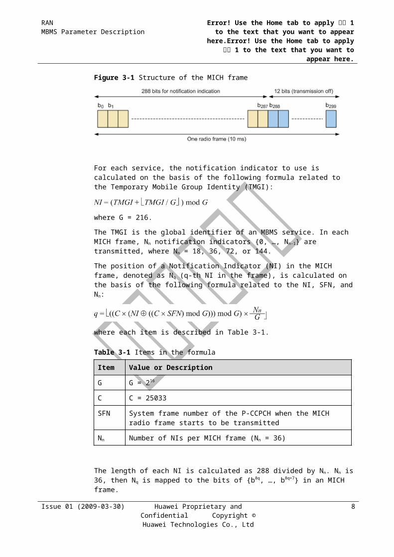
Figure 3-4 shows the frame structure of the MICH. One MICH radio frame at the length of 10 ms consists of 300 bits (b0, b1, …, b299), where the first 288 bits (b0, b1, …, b287) are used to carry notification indicators. The remaining 12 bits are neutral.
Figure 3-1 Structure of the MICH frame
For each service, the notification indicator to use is calculated on the basis of the following formula related to the Temporary Mobile Group Identity (TMGI):
where G = 216.
The TMGI is the global identifier of an MBMS service. In each MICH frame, Nn notification indicators {0, …, Nn-1} are transmitted, where Nn = 18, 36, 72, or 144.
The position of a Notification Indicator (NI) in the MICH frame, denoted as Nq (q-th NI in the frame), is calculated on the basis of the following formula related to the NI, SFN, and Nn:
where each item is described in Table 3-1.
Table 3-1 Items in the formula
Item Value or Description
G G = 216
Issue 01 (2009-03-30) Huawei Proprietary and Confidential Copyright © Huawei Technologies Co.,
Ltd
6

RANMBMS Parameter Description
Error! Use the Home tab to apply 标题 1 to the text that you want to appear here.Error! Use the Home
tab to apply 标题 1 to the text that you want to appear here.
Item Value or Description
C C = 25033
SFN System frame number of the P-CCPCH when the MICH radio frame starts to be transmitted
Nn Number of NIs per MICH frame (Nn = 36)
The length of each NI is calculated as 288 divided by Nn. Nn is 36, then Nq is mapped to the bits of {b8q, …, b8q+7} in an MICH frame.
The set of NI transmitted over the Iub interface indicates all the higher-layer NI values. For these values, the NI on the MICH should be set to 1 during the corresponding modification period and all the other NIs should be set to 0. Therefore, the previous formula should be used in the NodeB for every MICH frame to associate the NI with Nq.
Timing for Physical Channels
Figure 3-1 shows the radio frame timing of the MICH and the MCCH.
Figure 3-1 Radio frame timing of the MICH and the MCCH
The radio frames of the SCCPCH carrying MCCH can be transmitted 7680 chips after all the radio frames of the MICH are transmitted.
3.3 Basic MBMS Service Provision ProcessThis section describes the basic process of MBMS service.
3.3.1 Overview of MBMS Service Provision ProcessDepending on transmission requirements, the basic process of MBMS services can be performed repeatedly and the procedures for service announcement and MBMS notification can be performed together with the other procedures. This facilitates the access of UEs that have not received related services. Figure 3-1 shows the basic provision process of MBMS services.
Issue 01 (2009-03-30) Huawei Proprietary and Confidential Copyright © Huawei Technologies Co.,
Ltd
7

RANMBMS Parameter Description
Error! Use the Home tab to apply 标题 1 to the text that you want to appear here.Error! Use the Home
tab to apply 标题 1 to the text that you want to appear here.
Figure 3-1 Basic provision process of MBMS services
Service Announcement
Service announcement procedure announces the MBMS service information such as the IP multicast address and the other related parameters such as the service start time.
The service information can be announced in multiple ways, such as SMS cell broadcast, MBMS broadcast, PUSH mechanism (WAP, SMS-PP, and MMS), and URL (HTTP and FTP).
Session Start
Session start is the point at which the BM-SC is ready to send data. Session start information triggers the setup of bearer resources for sending MBMS data. For detailed information about session start process, see section 3.3.2 "MBMS Session Start Procedure".
MBMS Notification
MBMS notification informs the UE about the forthcoming and ongoing MBMS data transfer. For detailed information about MBMS notification, see section 3.3.3 "MBMS Notification".
Data Transfer
Data transfer is the phase when the BM-SC transfers MBMS data to the UE.
Session Stop
Session stop is the point at which the BM-SC determines that the MBMS data transfer is completed and the bearer resources are released. For detailed information on session stop process, see section 3.3.4 "MBMS Session Stop Procedure".
3.3.2 MBMS Session Start ProcedureThe BM-SC initiates the session start procedure before sending data. The procedure is performed to activate all the necessary bearer resources in the network for MBMS data transfer and notify the interested UE of the impending start of data transfer.
Issue 01 (2009-03-30) Huawei Proprietary and Confidential Copyright © Huawei Technologies Co.,
Ltd
8
RANMBMS Parameter Description
Error! Use the Home tab to apply 标题 1 to the text that you want to appear here.Error! Use the Home
tab to apply 标题 1 to the text that you want to appear here.
During this procedure, session attributes such as QoS, MBMS service area, estimated session duration, operating mode, and the MBMS data transfer start time are given from the BM-SC to the GGSNs, SGSNs and the RNCs in the MBMS service area. Figure 3-1 shows the MBMS session start procedure.
The MBMS service area can be specified by the CnOpIndex and MbmsSaId parameters by running the ADD MBMSSA command.
Figure 3-1 MBMS session start procedure
As shown in Figure 3-1, the session start procedure is performed as follows:
Step 1 The BM-SC sends a Session Start Request message to indicate the impending start of the data transfer and provide the session attributes such as TMGI, QoS, MBMS Service Area, estimated session duration, operating mode and a list of downstream nodes for the GGSN. The GGSN creates an MBMS Bearer Context (MBC), stores the session attributes and the list of downstream nodes in the MBC, sets the state attribute of its MBC to Active, and then sends a Session Start Response message to the BM-SC.
Step 2 The GGSN sends an MBMS Session Start Request message that contains the session attributes such as TMGI, QoS, MBMS service area, estimated session duration, and operating mode to the SGSNs listed in the MBC created in step 1. The SGSN creates an MBC, stores the session attributes in the MBC, sets the state attribute of its MBC to Active, and then responds with an MBMS Session Start Response message providing the TEID for the bearer plane that the GGSN uses to forward the MBMS data.
Step 3 The SGSN sends an MBMS Session Start Request message that contains the session attributes such as TMGI, QoS, MBMS service area, estimated session duration, and operating mode to each RNC that is connected to this SGSN. The RNC serving the MBMS service area creates an MSC, stores the session attributes in the MSC, sets the state attribute of its MSC, and then responds with an MBMS Session Start Response message providing the TEID for the Iu bearer plane that the SGSN uses to forward the MBMS data.
Step 4 The RNC that has created the MBMS Service Context chooses the transfer mode and establishes radio bearers according to the operating mode of the service and the algorithms
Issue 01 (2009-03-30) Huawei Proprietary and Confidential Copyright © Huawei Technologies Co.,
Ltd
9

RANMBMS Parameter Description
Error! Use the Home tab to apply 标题 1 to the text that you want to appear here.Error! Use the Home
tab to apply 标题 1 to the text that you want to appear here.
described in section 4.1 "MBMS Transfer Mode Selection" in each cell within the MBMS service area for the transfer of MBMS data to the interested UE.
----End
3.3.3 MBMS NotificationIn the MBMS notification procedure, the UE is notified of the change in the MBMS service through the MCCH.
The MBMS notification indicator corresponding to a specific MBMS service is sent continuously on the MICH during the entire modification period after the initial change is made in the MCCH information related to the service. Figure 3-1 shows the MICH timing related to the modification period.
Figure 3-1 MICH timing related to the modification period
When detecting the MBMS notification indication, the UE that is interested in the associated services reads MBMS Modified Service Information from the MCCH at the beginning of the next modification period.
The UE that is receiving MBMS services from the MTCH should receive MBMS Modified Service Information at the beginning of each modification period.
The MBMS Modified Service Information indicates the ID of an MBMS service whose MCCH information is modified at that modification period. If the MBMS Modified Service Information indicates the MBMS service ID activated by the UE, the UE reads the rest of the MCCH information.
3.3.4 MBMS Session Stop ProcedureThe BM-SC initiates the MBMS session stop procedure when deciding to stop the session.
The BM-SC sets the state attribute of its MBC to Standby. The related radio resources on the GGSN, SGSN, and RNC are released. Figure 3-1 shows the MBMS session stop procedure.
Issue 01 (2009-03-30) Huawei Proprietary and Confidential Copyright © Huawei Technologies Co.,
Ltd
10

RANMBMS Parameter Description
Error! Use the Home tab to apply 标题 1 to the text that you want to appear here.Error! Use the Home
tab to apply 标题 1 to the text that you want to appear here.
Figure 3-1 MBMS session stop procedure
As shown in Figure 3-1, the MBMS session stop procedure is performed as follows:
Step 1 The BM-SC sends a Session Stop Request message to indicate that the MBMS session is terminated and the bearer plane resources can be released. The BM-SC sets the state attribute of its MBC to Standby. The GGSN sends a Session Stop Response message to the BM-SC.
Step 2 The GGSN sends an MBMS Session Stop Request message to all SGSNs that have a session established with the GGSN, releases the corresponding bearer plane resources towards these SGSNs, and releases the MBC. The SGSN sends a Session Stop Response message to the GGSN.
Step 3 The SGSN releases the TEID and bearer plane resources of the affected MBMS, sends an MB9MS Session Stop Request message to all RNCs that have a session established with the SGSN, and releases the MBC. The RNC sends a Session Stop Response message to the SGSN.
Step 4 The RNC releases the affected radio and Iu resources and the MSC.
----End
3.4 MBMS Key FunctionsThis section describes the key functions of the MBMS service.
Issue 01 (2009-03-30) Huawei Proprietary and Confidential Copyright © Huawei Technologies Co.,
Ltd
11

RANMBMS Parameter Description
Error! Use the Home tab to apply 标题 1 to the text that you want to appear here.Error! Use the Home
tab to apply 标题 1 to the text that you want to appear here.
3.4.1 MBMS UTRAN Signaling Flows
MBMS Modified/Unmodified Service Information
Figure 3-1 Signaling flow of MBMS service information
In this procedure, the UE is notified of all MBMS services information in the cell.
The MBMS Modified/Unmodified Service Information message should be periodically sent on the MCCH to support MBMS mobility. In a modification period, if a service state has been changed compared with the state in the previous modification period, the information of the service is included in MBMS Modified Service Information. Otherwise, the information of the service is included in MBMS Unmodified Service Information.
The message contains the following information:
MBMS service ID
Service state indication such as PtM reception, PtP reception, counting indication, and so on.
MBMS PtM RB Information
Figure 3-1 Signaling flow of MBMS PtM RB information
This procedure is only intended for PtM transfer. The MBMS PtM RB information is periodically sent on the MCCH to support MBMS mobility.
The MBMS Common PtM RB Information message aims to notify the UE of the PtM RB configuration information that may be common between different MBMS services, applicable in the current or neighboring cells.
Issue 01 (2009-03-30) Huawei Proprietary and Confidential Copyright © Huawei Technologies Co.,
Ltd
12

RANMBMS Parameter Description
Error! Use the Home tab to apply 标题 1 to the text that you want to appear here.Error! Use the Home
tab to apply 标题 1 to the text that you want to appear here.
The MBMS Current Cell PtM RB Information message aims to notify the UE of the MTCH bearer information for services in PtM mode in the cell such as transport channel and physical channel information.
The MBMS Neighboring Cell PtM RB Information message aims to notify the UE of the MTCH configuration in the neighboring cell(s) so that the UE may perform selective or soft combining.
MBMS Access Information
Figure 3-1 Signaling flow of MBMS access information
This procedure is used to handle the MBMS UE in idle mode. This procedure is effective only for enhanced broadcast services.
The purpose of this procedure is for the RNC to inform the UE interested in a particular service of the potential need to make an MBMS counting response by initiating the establishment of an RRC connection. The MBMS Access Information is transmitted during counting and re-counting on the MCCH.
For each service that counting is required, the MBMS Access Information includes the MBMS service identifier and probability factor which is intended to control the uplink load according to simultaneous RRC Connection Requests. In every access information period, the UE draws a random number uniformly distributed in the range between 0% and 100%. The UE responds to the (re)counting only when the number is lower than the probability factor.
In Huawei RAN11.0, the probability factor may be changed on the basis of the repetition period during the counting. If no user responds to the counting in a repetition period, the probability factor is multiplied by two in the next repetition period. If some users respond to the counting, the probability factor keeps unchanged.
Issue 01 (2009-03-30) Huawei Proprietary and Confidential Copyright © Huawei Technologies Co.,
Ltd
13

RANMBMS Parameter Description
Error! Use the Home tab to apply 标题 1 to the text that you want to appear here.Error! Use the Home
tab to apply 标题 1 to the text that you want to appear here.
MBMS General Information
Figure 3-1 Signaling flow of MBMS General Information
In this procedure, the UE is notified of the general MBMS configuration in the cell, such as MBMS frequency layer information and MICH configuration.
The MBMS General Information message should be periodically sent on the MCCH to support MBMS mobility. The message contents do not change within a modification period.
MBMS Modification Request
Figure 3-1 Signaling flow of MBMS Modification Request
This procedure applies only to enhanced broadcast services.
This message can be sent by the UEs in URA_PCH, CELL_PCH, CELL_FACH or CELL_DCH state. The purpose of this procedure is to enable the UE to inform the RNC of MBMS service(s) selected by the user when the list of MBMS selected services in the UE has been modified, that is, the user has activated or deactivated some MBMS service(s).
MBMS Service Request
The MBMS service request procedure is used by a UE to request MBMS PtP reception. The procedure can be used when the MBMS is of enhanced broadcast mode and the transfer mode is PtP.
Issue 01 (2009-03-30) Huawei Proprietary and Confidential Copyright © Huawei Technologies Co.,
Ltd
14

RANMBMS Parameter Description
Error! Use the Home tab to apply 标题 1 to the text that you want to appear here.Error! Use the Home
tab to apply 标题 1 to the text that you want to appear here.
Figure 3-1 MBMS request procedure
As shown in Figure 3-1, the MBMS request procedure is performed as follows:
Step 1 An RRC connection is established if it does not exist.
Step 2 The UE sends a Service Request message to the SGSN for requesting MBMS PtP reception. The Service Type indicates "MBMS broadcast service reception". The message also triggers the establishment of a dedicated Iu signaling connection for the UE if it does not exist.
Step 3 The SGSN may perform the security functions.
Step 4 The SGSN provides the RAN with the IMSI of the UE.
Step 5 The RNC establishes the necessary radio resources for the transfer of MBMS data to the interested UE.
Step 6 When PtP transmission of an MBMS service is active for a UE, the RNC supervises the Iu signaling connection. The RNC keeps the dedicated Iu signaling connection during MBMS PtP reception even when there is no dedicated Iu activity for this UE. When the RNC determines that it does not need to keep the dedicated Iu signaling connection anymore, it initiates a normal Iu release request towards the SGSN. The SGSN does not release the Iu signaling connection until it receives a request from the RNC.
----End
3.4.2 Selective and Soft CombiningSelective and soft combining are enhanced features of receiving MBMS data in PtM mode to improve the receiving sensitivity at the UE side.
Issue 01 (2009-03-30) Huawei Proprietary and Confidential Copyright © Huawei Technologies Co.,
Ltd
15

RANMBMS Parameter Description
Error! Use the Home tab to apply 标题 1 to the text that you want to appear here.Error! Use the Home
tab to apply 标题 1 to the text that you want to appear here.
Selective Combining
Figure 3-1 shows the procedure of selective combining.
Figure 3-1 Procedure of selective combining
The RNC sends the same MBMS data in PtM mode on the SCCPCHs of different cells at the same time. The UE receives and decodes the MBMS data from multiple links simultaneously. In the RLC layer, the UE selects the transport block from one radio link according to the Cyclic Redundancy Check (CRC) results and the RLC PDU sequence number.
Soft Combining
As shown in Figure 3-1, soft combining is performed when different NodeBs are synchronized within the soft combining receiving window (1 TTI + 1 timeslot) of the UE. In this case, the data domain of the combined SCCPCHs is the same.
Issue 01 (2009-03-30) Huawei Proprietary and Confidential Copyright © Huawei Technologies Co.,
Ltd
16

RANMBMS Parameter Description
Error! Use the Home tab to apply 标题 1 to the text that you want to appear here.Error! Use the Home
tab to apply 标题 1 to the text that you want to appear here.
Figure 3-1 Procedure of soft combining
During the Transmission Timing Interval (TTI) to be soft combined, the UE receiver combines signals from different cells either when the RAKE receives signals or before channel decoding (for example, after the RAKE receives the signals).
When a cell supports the UE to perform selective or soft combining from the cell and its neighboring cell(s), the UTRAN sends the MBMS Neighboring Cell PtM RB Information message in the cell. This message contains the MTCH information of the neighboring cells that can be combined. When receiving the message, the UE can receive the MTCH of neighboring cells without reading their MCCHs.
The current version supports data transmission synchronization between cells that meet the requirement of soft combining and are within the scope of one RNC. Selective or soft combining from cells under different RNCs is not supported because different RNCs segment and encapsulate the data blocks separately, which results in data blocks received from different cells being not combinable.
3.4.3 Frequency Layer Convergence and DispersionThe frequency layer convergence and dispersion functions can be performed in case of multiple-frequency network.
Frequency Layer Convergence
If the Frequency Layer Convergence (FLC) function is enabled, when a UE begins to receive an MBMS service, the UE preferentially reselects the frequency layer on which the MBMS service is intended to be transmitted according to the UTRAN indication.
The Preferred Layer (PL) is indicated in each MBMS service. The UTRAN can have multiple PLs. The PL in each MBMS service is determined by the Radio Resource Management
Issue 01 (2009-03-30) Huawei Proprietary and Confidential Copyright © Huawei Technologies Co.,
Ltd
17

RANMBMS Parameter Description
Error! Use the Home tab to apply 标题 1 to the text that you want to appear here.Error! Use the Home
tab to apply 标题 1 to the text that you want to appear here.
(RRM). Therefore, the same MBMS service can be located at different PLs in different parts of the service area.
To enable the FLC in PtM mode, set the parameter FlcAlgoSwitch to ON by running the ADD CELLMCCH command.
To enable the FLC in PtP mode, set the MBMS_FLC_SWITCH of SrnsrSwitch parameter to ON by running the SET CORRMALGOSWITCH command.
Frequency Layer Dispersion
If the Frequency Layer Dispersion (FLD) function is enabled, when a UE stops an MBMS service, the UE reselects the cells with different frequency according to the UTRAN indication, and decides whether the FLD needs to be used for each MBMS session. FLD can prevent the UEs from camping on a single cell.
Upon the receipt of the FLC information on the MCCH, the UE may reselect another frequency. The UE stores the original frequency. When the MBMS session stops, the UE may attempt to return to the original frequency.
The FLD is applicable only when the UE is in idle mode, or in URA_PCH, CELL_PCH, or CELL_FACH state.
The FLD only indicates whether the reselection is required on the network side; whether the UE will take action depends on the implementation of the FLD.
3.4.4 Iub Transmission OptimizationIn the pre-R7 specification of 3GPP, each transport channel has a dedicated Iub transport bearer that is established and released along with the associated transport channel.
The enhanced features in the 3GPP R7 specification allow multiple transport channels to be mapped on a common Iub transport bearer. Thus, the Iub bandwidth for MBMS is saved. With this improvement, the RNC can send only a copy of data for each Iub for the PtM transmission of an MBMS session. Then, the data is copied within the NodeB and distributed to each MTCH that bears the service, as illustrated in Figure 3-1.
Figure 3-1 Effect of Iub transmission optimization
This feature is always enabled in the current version.
Issue 01 (2009-03-30) Huawei Proprietary and Confidential Copyright © Huawei Technologies Co.,
Ltd
18

RANMBMS Parameter Description
Error! Use the Home tab to apply 标题 1 to the text that you want to appear here.Error! Use the Home
tab to apply 标题 1 to the text that you want to appear here.
3.4.5 Counting ProcedureMBMS counting is used to determine the optimum transfer mode, that is, PtP or PtM, for a given service. The procedure applies only to enhanced MBMS broadcast services.
The counting procedure is also available only in cells for which the parameter MBMS transfer mode (MbmsTransMode) is set to ENHANCEDPTM or DYNAMIC as described in section 4.1 "MBMS Transfer Mode Selection". The counting is performed in each cell within the corresponding MBMS service area.
In the phase of session start for a service, the RNC initiates the counting procedure to determine the initial transfer mode for the service. During a PtM MBMS session, the RNC will periodically perform the counting procedure based on the recounting period (RecountingPeriod) to check whether the PtM is still the optimal transfer mode. This procedure is called recounting.
UEs in URA_PCH, CELL_PCH, CELL_FACH, or CELL_DCH state always send MBMS Modification Request to the RNC to indicate the service(s) currently the user have selected, thus the network always has the updated knowledge of MBMS services selected by UEs in RRC connected state. Therefore, the (re)counting procedure only applies to UEs in idle state.
The RNC may trigger (re)counting for a given service by using MBMS notification mechanism as described in section 3.3.3 "MBMS Notification" to indicate that the concerned service needs counting. UEs in idle mode and have interest in the concerned service will obtain the MBMS Access Information on MCCH and attempt to respond to counting.
The counting procedure lasts until the criteria for stopping counting as described in section 4.1 "MBMS Transfer Mode Selection" is fulfilled or the duration of the counting reaches the up limit counting time(UpLimitCountingTime).
3.4.6 MBMS Over IurHuawei RAN11.0 supports the inter-RNC mobility management, including the handover from the cell under one RNC to the PtP or PtM cell under another RNC.
When the UE that receives the MBMS data in PtP mode moves to the PtP cell under another RNC:
− If the Iur interface exists, the soft handover over Iur is triggered directly.
− If the Iur interface does not exist, the relocation with hard handover is triggered directly.
When the UE that receives the MBMS data in PtP mode moves to the PtM cell under another RNC:
− If the Iur interface exists, the SRNC notifies the UE that the transfer mode has changed. Then, the UE releases the PtP connection and then receives the MBMS services in PtM mode.
− If the Iur interface does not exist, first the relocation with hard handover is triggered directly, and then the SRNC notifies the UE that the transfer mode has changed. Then, the UE releases the PtP connection and then receives the MBMS services in PtM mode.
When the UE in CELL_FACH, CELL_PCH, or URA_PCH state that receives the MBMS data in PtM mode moves to the PtP cell under another RNC:
− If the Iur interface exists, the RRC connection is released directly, which enables the UE to initiate a connection request again in the PtP cell.
Issue 01 (2009-03-30) Huawei Proprietary and Confidential Copyright © Huawei Technologies Co.,
Ltd
19

RANMBMS Parameter Description
Error! Use the Home tab to apply 标题 1 to the text that you want to appear here.Error! Use the Home
tab to apply 标题 1 to the text that you want to appear here.
− If the Iur interface does not exist, the UE directly initiates the connection request in the PtP cell.
When the UE in CELL_FACH, CELL_PCH, or URA_PCH state that receives the MBMS data moves to the PtM cell under another RNC:
− If the Iur interface exists, the RRC connection is released directly, which enables the UE to initiate a connection request again in the PtM cell.
− If the Iur interface does not exist, the UE directly receives the MBMS data in the PtM cell.
Huawei RAN11.0 supports the transfer of the MBMS Channel Type Indication message over the Iur interface. Thus, the transfer mode information of the cell under the DRNC cell is dynamically sent to the SRNC, which enables the SRNC to freely hand over UEs over the Iur interface between the PtP and PtM cells under the DRNC.
For detailed information about the MBMS Channel Type Indication functions and the MBMS over Iur process, see 3GPP TS 25.433 and 3GPP TS 25.931.
Issue 01 (2009-03-30) Huawei Proprietary and Confidential Copyright © Huawei Technologies Co.,
Ltd
20

RANMBMS Parameter Description
Error! Use the Home tab to apply 标题 1 to the text that you want to appear here.Error! Use the Home
tab to apply 标题 1 to the text that you want to appear here.
4 MBMS RRM Algorithms
4.1 MBMS Transfer Mode SelectionThe MBMS transfer mode selection algorithm makes the MBMS transfer mode selection more flexible and efficient, and ensures both high QoS and optimal resource utilization.
There are four options for the algorithm of MBMS transfer mode (MbmsTransMode) selection:
PtM: static PtM mode
PtP: static PtP mode
ENHANCEDPTM: enhanced PtM mode
DYNAMIC: dynamic PtP/PtM mode
These options apply to the enhanced broadcast services only, whereas for the broadcast services, the PtM transmission is always used on the Uu interface.
4.1.1 Static PtM ModeIn this mode, the PtM transmission will always be used, regardless of how many users receive the given service in the cell. The counting procedure is not performed during the session and the MBMS services are always carried on the FACH.
4.1.2 Static PtP ModeIn this mode, the PtP transmission will always be used, regardless of how many users receive the given service in the cell. The counting procedure is not performed during the session and the MBMS services can be carried on the DCH or the HS-DSCH, depending on the same strategy as for other services. For the detailed information about the strategy, see Radio Bearer Parameter Description.
4.1.3 Enhanced PtM ModeIn this mode, the PtM transmission will be used if at least one user is interested in the given service. If no user is interested in the given service, then data is not transmitted in the cell. The procedure of the algorithm is as follows:
Step 1 In the start phase of the session, the RNC initiates an initial counting procedure according to "Counting Procedure". For a cell, if at least one user responds to the counting, the counting
Issue 01 (2009-03-30) Huawei Proprietary and Confidential Copyright © Huawei Technologies Co.,
Ltd
1

RANMBMS Parameter Description
Error! Use the Home tab to apply 标题 1 to the text that you want to appear here.Error! Use the Home
tab to apply 标题 1 to the text that you want to appear here.
procedure is terminated and the transfer mode in the cell will be set to PtM. If no user responds to the counting, the transfer mode is set to PtP.
Step 2 For the cells in PtP mode, if the RNC receives the MBMS PtP receiving request as described in MBMS Service Request in section 3.4.1 "MBMS UTRAN Signaling Flows", or MBMS Modification Request message in which the UE indicates the selection of the service concerned, the RNC immediately changes the transfer mode to PtM and starts transmitting the given service on the radio interface.
Step 3 For the cells in PtM mode, in every recounting period, if the RNC does not know any UEs that receive the service, the RNC initiates the recounting procedure. If at least one UE responds to the counting, the transfer mode remains PtM. If no UE responds to the counting, the transfer mode is changed to PtP.
In this algorithm, the network never transmits service data through the PtP bearer, even when the transfer mode is set to PtP. The indication of PtP on the MCCH is only used to trigger the MBMS PtP service request procedure so that the network detects in this cell the UE that is interested in the service and then starts the PtM transmission immediately.
----End
4.1.4 Dynamic PtP/PtM ModeHuawei RAN11.0 introduces advanced algorithms in dynamic PtP or PtM mode, which ensures both high QoS and efficient network resource utilization.
Dual counting thresholds
The transfer mode switching between PtP and PtM requires the UE to release the old RBs and establish the new RB. This may temporarily interrupt the service reception. To prevent frequent transfer mode switching in a cell, the transfer mode selection uses the following dual counting thresholds:
− The parameter NCountingThd is used for the initial counting or the recounting. If the number of counted UEs(contains the UEs in RRC connected mode) is lower than the value of NCountingThd, the transfer mode is set to PtP; otherwise, the transfer mode is set to PtM.
− The parameter NPtpToPtmOffset is used for services in PtP mode to determine whether switching to PtM mode is required according to the number of PtP reception requests from UEs. If the number of users that request PtP reception for the given service in the cell is lower than the value of NCountingThd plus NPtpToPtmOffset, the transfer mode is kept as PtP; otherwise, the transfer mode is set to PtM.
Issue 01 (2009-03-30) Huawei Proprietary and Confidential Copyright © Huawei Technologies Co.,
Ltd
2

RANMBMS Parameter Description
Error! Use the Home tab to apply 标题 1 to the text that you want to appear here.Error! Use the Home
tab to apply 标题 1 to the text that you want to appear here.
Figure 4-1 Thresholds for the transfer mode switching between PtP and PtM
In Huawei RAN11.0 implementation, switching from PtP to PtM is time-triggered rather than event-triggered. In the case of PtP transmission, the network checks the number of UEs that have a dedicated link for the given service and decides whether to switch the transfer mode only at the time point of recounting. The PtP service link request from a UE will not trigger the transfer mode switching from PtP to PtM before the next recounting session.
XOffset for users in connected mode during PtM transmission
Excessive recounting may have some negative impacts that may increase the uplink traffic load and interrupt the PtM reception of UEs that cannot read the MTCH in CELL_DCH state.
The UEs in connected mode will always indicate the selected services to the network; therefore, if there are already enough UEs in connected mode, the network does not need to initiate the recounting procedure on the Uu interface. This will mitigate the negative impacts of recounting.
The basic principle of (re)counting algorithm in dynamic PtP/PtM mode is as follows:
When the number of UEs in RRC connected mode is greater than the value of NCountingThd plus XOffset during the (re)counting, the (re)counting procedure is stoped. Then, even some UEs are connected to or disconnected from the network, the PtM mode is maintained and the (re)counting is not triggered as long as the number of UEs in connected mode is greater than the value of NCountingThd.The procedure of the algorithm is as follows:
− If the transfer mode is set to PtP, the RNC always knows the exact number of UEs that receive the service in the cell.
− During the initial counting or recounting, the counting procedure will last until the number of UEs in RRC connected mode reaches the value of NCountingThd plus XOffset. The UEs in RRC connected mode include UEs in CELL_DCH, CELL_FACH, or CELL_PCH state for other services and UEs that respond to (re)counting. After (re)counting, the UEs that respond to the (re)counting will be kept in CELL_PCH state and UEs in RRC connected states for other services will be kept in their original states.
Assistant PtM transmission
Issue 01 (2009-03-30) Huawei Proprietary and Confidential Copyright © Huawei Technologies Co.,
Ltd
3

RANMBMS Parameter Description
Error! Use the Home tab to apply 标题 1 to the text that you want to appear here.Error! Use the Home
tab to apply 标题 1 to the text that you want to appear here.
As selective combining and soft combining can improve the quality of service reception, especially for the UEs at the cell edge, a lightly loaded cell can switch the transfer mode to PtM to assist its neighboring PtM cell(s). The details of the algorithm are as follows:
− A cell has a configurable MBMS neighboring cell (MbmsNCellInd) group, which is a subset of its intra-frequency neighboring cells.
− For the cell not in basic congestion, it will stay in PtM mode regardless of the (re)counting result if at least one cell in its MBMS neighboring cell group transmits the given service in PtM mode. Otherwise, the transfer mode will be determined by the (re)counting result of the cell.
− For the cell in basic congestion status, the transfer mode will be determined by the (re)counting result of the cell.
Note that a cell that is performing assistant PtM transmission will not trigger the assistant PtM transmission in its neighboring cells.
4.2 MBMS Dynamic Power Setting in PtM ModeThere is no power control for the SCCPCH as for the DCH; therefore, MTCH power is always set high enough to guarantee a good coverage in the whole cell, especially at the cell edge. Also, selective and soft combining enable the UE to combine several MTCHs from different cells. This improves the receiver sensitivity significantly. As a result, the required Ec/Io for each path is decreased while the target Block Error Rate (BLER) keeps unchanged.
Huawei RAN11.0 supports dynamic MTCH power adjustment for a cell according to the transfer modes of its neighboring cells. The procedure for dynamic MTCH power adjustment is as follows:
One specific threshold is introduced, that is, CombNCellPercent, which represents a percentage of intra-frequency neighboring cells in PtM mode among all the intra-frequency neighboring cells of the cell.
For a cell, if the proportion of neighboring PtM cells exceeds the value of CombNCellPercent, the normal power of the corresponding MTCH will be decreased by a soft combination power offset which equals 5 dB.
Otherwise, the power of the corresponding MTCH will be set to the normal value.
4.3 MBMS Admission Control
4.3.1 Power AdmissionTwo power values are set for each MBMS service:
Maximum FACH transmit power, which is set by FachMaxPower.
Minimum FACH transmit power, which is calculated as follows:
Issue 01 (2009-03-30) Huawei Proprietary and Confidential Copyright © Huawei Technologies Co.,
Ltd
4
RANMBMS Parameter Description
Error! Use the Home tab to apply 标题 1 to the text that you want to appear here.Error! Use the Home
tab to apply 标题 1 to the text that you want to appear here.
Table 4-1 Variables in the formula
Variable
Description Related Parameter
PMinFACHTx Minimum FACH transmit power. None
PMaxFACHTx Maximum FACH transmit power. FachMaxPower
C0 The least coverage rate of the MTCH with RAB priority 0, namely the highest priority.
MtchMinPerc0
C15 The least coverage rate of the MTCH with RAB priority 15, namely the lowest priority.
MtchMinPerc15
L RAB priority of the MBMS service None
In the power admission phase, the power for an MBMS service is determined as follows:
If the current cell is not in basic congestion status, the maximum FACH transmit power of the service is always used to make an admission decision.
If the current cell is in basic congestion status and the RAB priority value of the service is higher than the value of MbmsDecPowerRabThd, that is, the service has lower priority, the minimum FACH transmit power is used to make an admission decision; if the RAB priority value of the service is equal to or smaller than the value of MbmsDecPowerRabThd, that is, the service has higher priority, the maximum FACH transmit power is used.
In Huawei RAN11.0, two thresholds are introduced to control the power consumption of MBMS services in a cell:
MTCH maximal power threshold: If the ratio of power occupied by all MTCHs to the total DL transmit power of the cell reaches or exceeds this threshold, more power will not be allocated for MTCHs in the cell. The MTCH maximal power threshold can be set through the MtchMaxPwr parameter.
MTCH reserved power threshold: If the proportion of power occupied by all MTCHs to the total DL transmit power of the cell is equal to or lower than this threshold, the existing MTCHs cannot be pre-empted by other services regardless of the service priority. The MTCH reserved power threshold can be set through the MtchRsvPwr parameter.
The principles of power admission for MBMS services are as follows:
MBMS PtP RB admission:
The call admission control (CAC) algorithm applied to the request of MBMS PtP RB is the same as that applied to other services. For details about the CAC algorithm, see the Load Control Parameter Description.
MBMS PtM RB admission:
− If the total MTCH power in the cell exceeds the MTCH Maximal Power Threshold, then the request for setting up a new MTCH is rejected, regardless of the current cell load.
− Otherwise, the power admission of a new MTCH applies the CAC algorithm.
Issue 01 (2009-03-30) Huawei Proprietary and Confidential Copyright © Huawei Technologies Co.,
Ltd
5

RANMBMS Parameter Description
Error! Use the Home tab to apply 标题 1 to the text that you want to appear here.Error! Use the Home
tab to apply 标题 1 to the text that you want to appear here.
4.3.2 Code AdmissionIn Huawei RAN11.0, two thresholds are introduced to control the code occupation of MBMS services in a cell:
MTCH Maximal SF Threshold: If the number of codes occupied by all MTCHs reaches or exceeds this threshold, more codes will not be allocated for MTCH in the cell. The MTCH maximal SF threshold can be set through the MtchMaxSf parameter.
MTCH Reserved SF Threshold: If the number of codes occupied by all MTCHs is equal to or less than this threshold, the existing MTCHs cannot be pre-empted by other services regardless of the service priority. The MTCH reserved SF threshold can be set through the MtchRsvSf parameter.
The codes allocated to MBMS PtM RBs are not necessarily required to be continuous.
The principles of code admission for MBMS services are as follows:
MBMS PtP RB admission:
The CAC algorithm applied to the request of MBMS PtP RB is the same as that applied to other services.
MBMS PtM RB admission:
− If the number of MTCH codes in the cell exceeds the MTCH Maximal SF Threshold, then the request for setting up a new MTCH is rejected, regardless of the current cell load.
− If the number of MTCH codes in the cell does not exceed the MTCH Maximal SF Threshold, the code admission of a new MTCH complies with the CAC algorithm.
4.3.3 Iub and Credit AdmissionThe Iub and credit admission criterion applied to the request of MBMS PtP/PtM RB is the same as that applied to other services.
4.4 MBMS Pre-emption ControlFor a given MBMS service, all the PtP and PtM RBs inherit the same RAB parameters in the MBMS Session Start Request message sent from CN to RNC.
Huawei RAN11.0 introduces three switches to facilitate QoS control differentiation between PtP RBs and PtM RBs with the same service. Table 4-2 describes the parameters related to MBMS pre-emption control.
Table 4-1 Parameters related to MBMS pre-emption control
Parameter Description
PtmPreemptSwitch Indicates whether MBMS PtM RBs can pre-empt other RBs (including MBMS PtP/PtM RBs and non-MBMS RBs).
PtmStrmPasiSwitch Indicates whether MBMS PtM streaming RBs can be pre-empted by other RBs (including MBMS PtP/PtM RBs and non-MBMS RBs).
Issue 01 (2009-03-30) Huawei Proprietary and Confidential Copyright © Huawei Technologies Co.,
Ltd
6

RANMBMS Parameter Description
Error! Use the Home tab to apply 标题 1 to the text that you want to appear here.Error! Use the Home
tab to apply 标题 1 to the text that you want to appear here.
Parameter Description
PtmNullStrmPasiSwitch Indicates whether MBMS PtM non-streaming RBs can be pre-empted by other RBs (including MBMS PtP/PtM RBs and non-MBMS RBs).
These switches together with RAB parameters, namely, Pre-emption Capability and Pre-emption Vulnerability, determine the actual pre-emption attributes of the MBMS PtP and PtM RBs.Table 4-2, Table 4-3, and Table 4-4 describe the combinations of these parameters.
Table 4-2 Pre-emption capability control
PtmPreemptSwitch
Pre-emption Capability
Can MBMS PtM RBs Pre-empt Other RBs?
Can MBMS PtP RBs Pre-empt Other RBs?
ON May trigger pre-emption
Yes Yes
ON Shall not trigger pre-emption
No No
OFF May trigger pre-emption
No Yes
OFF Shall not trigger pre-emption
No No
Table 4-3 Pre-emption vulnerability control for PtM streaming services
PtmStrmPasiSwitch
Pre-emption Vulnerability
Can MBMS PtM Streaming RBs Be Pre-empted by Other RBs?
Can MBMS PtP Streaming RBs Be Pre-empted by Other RBs?
ON Can be pre-empted Yes Yes
ON Cannot be pre-empted
No No
OFF Can be pre-empted No Yes
OFF Cannot be pre-empted
No No
Issue 01 (2009-03-30) Huawei Proprietary and Confidential Copyright © Huawei Technologies Co.,
Ltd
7

RANMBMS Parameter Description
Error! Use the Home tab to apply 标题 1 to the text that you want to appear here.Error! Use the Home
tab to apply 标题 1 to the text that you want to appear here.
Table 4-4 Pre-emption vulnerability control for PtM non-streaming services
PtmNullStrmPasiSwitch
Pre-emption Vulnerability
Can MBMS PtM Non-Streaming RB Be Pre-empted by Other RBs?
Can MBMS PtP Non-Streaming RB Be Pre-empted by Other RBs?
ON Can be pre-empted
Yes Yes
ON Cannot be pre-empted
No No
OFF Can be pre-empted
No Yes
OFF Cannot be pre-empted
No No
The pre-emption criterion takes the following factors into consideration:
Four thresholds for power and code allocation control of MBMS services.
Pre-emption Capability and Vulnerability Control (PCVC) for the MBMS.
RAB priority, that is, allocation retention priority (ARP) and traffic class (TC).
Table 4-5 describes the detailed pre-emption criterion.
Table 4-5 Pre-emption criterion
Cases of resources occupation by PtM RBs
Pre-emption caused by new PtM RB request
Pre-emption caused by new PtP/non-MBMS RB request
Can PtM RB pre-empt Other PtM RB?
Can PtM RB pre-empt PtP/non-MBMS RB?
Can PtP/non-MBMS RB pre-empt PtM RB?
Can PtP/non-MBMS RB pre-empt Other PtP/non-MBMS RB?
Treserv ed
Tmax
When the power and codes consumed by the MBMS PtM RBs in a cell do not exceed the MTCH Reserved Power Threshold and MTCH Reserved SF Threshold respectively
No Yes, based on PCVC and RAB priority.
No Yes, based on PCVC and RAB priority.
Issue 01 (2009-03-30) Huawei Proprietary and Confidential Copyright © Huawei Technologies Co.,
Ltd
8

RANMBMS Parameter Description
Error! Use the Home tab to apply 标题 1 to the text that you want to appear here.Error! Use the Home
tab to apply 标题 1 to the text that you want to appear here.
Cases of resources occupation by PtM RBs
Pre-emption caused by new PtM RB request
Pre-emption caused by new PtP/non-MBMS RB request
Can PtM RB pre-empt Other PtM RB?
Can PtM RB pre-empt PtP/non-MBMS RB?
Can PtP/non-MBMS RB pre-empt PtM RB?
Can PtP/non-MBMS RB pre-empt Other PtP/non-MBMS RB?
Treserv ed
Tmax
When the power and codes consumed by the MBMS PtM RBs in a cell do not exceed the MTCH Maximal Power Threshold and MTCH Maximal SF Threshold respectively
And when either of the power or codes consumed by the MBMS PtM RBs exceeds the MTCH Reserved Power Threshold or MTCH Reserved SF Threshold respectively
Yes, based on PCVC and RAB priority.
Yes, based on PCVC and RAB priority.
Yes, based on PCVC and RAB priority.
Yes, based on PCVC and RAB priority.
Treserv ed
Tmax
When either of the power or codes consumed by the MBMS PtM RBs in a cell exceeds the MTCH Maximal Power Threshold or MTCH Maximal SF Threshold respectively
Yes, based on PCVC and RAB priority.
No Yes, based on PCVC and RAB priority.
Yes, based on PCVC and RAB priority.
Different actions will be taken when the pre-emptions caused by different RBs fail:
In the case that the new MBMS PtM RB fails in pre-emption, the RNC will periodically re-attempt to establish the RB if the RB is triggered by session start, or the RNC will keep the transfer mode of corresponding service as PtP if the RB is triggered by switching from PtP to PtM.
In the case that the new MBMS PtP RB fails in pre-emption, the RNC will indicate the MBMS-required UE action as none on the MCCH for PunishTime to prevent the UE from re-attempting to request the PtP RB.
Issue 01 (2009-03-30) Huawei Proprietary and Confidential Copyright © Huawei Technologies Co.,
Ltd
9

RANMBMS Parameter Description
Error! Use the Home tab to apply 标题 1 to the text that you want to appear here.Error! Use the Home
tab to apply 标题 1 to the text that you want to appear here.
5 Impact of MBMS on Other
Features
5.1 Impact of MBMS on Admission and Pre-emption Control
MBMS services have different criteria of admission and pre-emption control, as opposed to other services. Also, MBMS has impacts on the pre-emption control for other services. For detailed information, see section 4.3 "MBMS Admission Control" and section 4.4 "MBMS Pre-emption Control".
5.2 MBMS Related Actions in LDRThe action of MBMS power reduction added to Load Reshuffling (LDR) is described as follows:
The RNC sorts all MBMS services in the cell whose RAB priority values are higher than MBMS descend power RAB threshold (MbmsDecPowerRabThd), that is, the services have lower priorities. The RAB priority values are arranged in descending order. The RNC selects the first service in the list that works with its Max FACH Transmit Power and reduces the power of the service to its Min FACH Transmit Power. After that, the action ends.
For the MBMS PtP RBs, only code reshuffling action can be performed.
5.3 MBMS Related Actions in OLCThe MBMS PtP/PtM RBs can be released during Overload Control (OLC). For details, see the Load Control Parameter Description.
The MBMS PtP RBs cannot be chosen to restrict the Transport Format (TF) or switch to the common channel.
Issue 01 (2009-03-30) Huawei Proprietary and Confidential Copyright © Huawei Technologies Co.,
Ltd
1
RANMBMS Parameter Description
Error! Use the Home tab to apply 标题 1 to the text that you want to appear here.Error! Use the Home
tab to apply 标题 1 to the text that you want to appear here.
6 MBMS Parameters
6.1 Description
Table 6-1 MBMS parameter description
Parameter ID Description
CNOPERATORINDEX
Cn Operator Index.
CombNCellPercent For a PTM service, if the ratio of the intra-frequency cells where the service is transmitted in PTM mode to the intra-frequency cells of a cell reaches the percentage specified by this parameter, the cell has gains in combining. Then, the power of the FACH carrying the service in the cell decreases by [PARA]SoftCombPwrOffset[/PARA].
NCountingThd When the number of UEs responding to counting/recounting is greater than or equal to this threshold, the PTM mode is applied to data transmission. Otherwise, the PTP mode is used. Note that the number of UEs includes the number of connected mode UEs. A larger value of this parameter leads to a higher probability of using PTP transmission on the network. Power control is available for PTP transmission, and thus the power consumption in PTP mode is lower than that in PTM mode. In PTP mode, however, the quantities of code, CE, and other transmission resources increase with the number of users. Therefore, the setting of this parameter should take into consideration various resources, especially bottleneck resources of operators. The value of this parameter should not be too large.
FachMaxPower This parameter specifies the maximum power of the FACH.
FlcAlgoSwitch Switch of the FLC algorithm. The FLC is a mandatory algorithm used in the multi-frequency network to guarantee that UEs camping on other frequencies can reselect the current frequency to receive the MBMS service. Therefore, the switch is on by default.
MbmsDecPowerRabThd
When the priority of the RAB of MBMS services exceeds this threshold, reconfigure the MBMS power to the minimum power. The lower the parameter value is, the bigger the scope for selecting the MBMS services is, the more cell load is decreased, the more effect there is on the MBMS service. At the same time, the cell overload is significantly decreased while the impact on the MBMS services becomes bigger. The higher the parameter value is, the smaller the scope for selecting the MBMS services is, the less cell load is decreased, the more effect there is on the MBMS services, and the quality of
Issue 01 (2009-03-30) Huawei Proprietary and Confidential Copyright © Huawei Technologies Co.,
Ltd
1

RANMBMS Parameter Description
Error! Use the Home tab to apply 标题 1 to the text that you want to appear here.Error! Use the Home
tab to apply 标题 1 to the text that you want to appear here.
Parameter ID Description
services with high priority, however, can be guaranteed. The MBMS service at each rate is set on the basis of two power levels. The power set for an MBMS service is determined according to cell load during the service access. In addition, the FACH power of the MBMS service must be decreased as required in the duration of cell congestion. Some services with high priority, for example the disaster pre-alert, however, do not need the coverage shrink caused by cell load. In such a case, you can adjust the service priority threshold to protect the services with high priority against the impact of the service access failure and the load control algorithm.
MbmsNCellInd It is an indicator of MBMS neighboring cell.
MbmsSaId MBMS SA ID. For detailed information of this parameter, refer to the 3GPP 25.346.
MbmsTransMode This parameter specifies the transport mode of MBMS services. The point-to-multipoint (PTM), point-to-point (PTP), and enhanced PTM (ENHANCEDPTM) modes are static or semi-static transport modes. They are relatively simple and have little impact on the MBMS service and the network performance. The dynamic mode (DYNAMIC) is complicated. In dynamic mode, transition between PTP and PTM modes is performed dynamically to balance the quality of service and the network resource utilization. The network periodically changes the transport mode based on the number of users and the status of neighboring cells. These activities have an impact on the reception of the MBMS service, and the MBMS user might experience service disruption when the user moves across the border between PTP cell and PTM cell. Therefore, the dynamic mode has a relatively great impact on the MBMS service and the network performance. For details of this parameter, refer to the 3GPP TS 25.346.
MtchMinPerc15 This parameter specifies the minimum coverage percentage of the MTCH corresponding to the RAB priority of 15. When the cell load is high, the RNC configures low power for the MBMS service so as to avoid worsening congestion in the cell and improve the setup success rate of the MBMS service. This low power, however, should cover the minimum coverage area of the MBMS service. The minimum coverage area is set to a certain percentage of the coverage area associated with the maximum transmit power of the FACH. To fulfill service differentiation, services of different priorities have different minimum coverage areas. A larger value of this parameter leads to a larger guaranteed coverage area of the MBMS service in the case of heavy load in the cell. For details of this parameter, refer to the 3GPP TS 25.346.
MtchMinPerc0 This parameter specifies the minimum coverage percentage of the MTCH corresponding to the RAB priority of 0. When the cell load is high, the RNC configures low power for the MBMS service so as to avoid worsening congestion in the cell and improve the setup success rate of the MBMS service. This low power, however, should cover the minimum coverage area of the MBMS service. The minimum coverage area is set to a certain percentage of the coverage area associated with the maximum transmit power of the FACH. To fulfill service differentiation, services of different priorities have different minimum coverage areas. A larger value of this parameter leads to a larger guaranteed coverage area of the MBMS service in the case of heavy load in the cell. For details of this parameter, refer to the 3GPP TS 25.346.
PtmNullStrmPasiSwitch
This parameter specifies whether MBMS PTM non-streaming bearers can be pre-empted by other MBMS PTM bearers or non-MBMS bearers. If this parameter is set to ON, a PTM non-streaming bearer might be pre-empted by an MBMS bearer of a higher priority or a non-MBMS bearer in the case of congestion. Thus, the MBMS service is disrupted, which has a relatively great impact because the PTM bearer serves more than
Issue 01 (2009-03-30) Huawei Proprietary and Confidential Copyright © Huawei Technologies Co.,
Ltd
2

RANMBMS Parameter Description
Error! Use the Home tab to apply 标题 1 to the text that you want to appear here.Error! Use the Home
tab to apply 标题 1 to the text that you want to appear here.
Parameter ID Description
one user.
PtmPreemptSwitch This parameter specifies whether MBMS PTM streaming bearers can pre-empt other MBMS PTM bearers and non-MBMS bearers. If this parameter is set to ON, pre-emption is triggered when PTM streaming bearer admission fails. That is, a lower-priority MBMS bearer or a non-MBMS bearer is released. Thus, the ongoing service is disrupted and call drop even occurs.
PtmStrmPasiSwitch
This parameter specifies whether MBMS PTM streaming bearers can be pre-empted by other MBMS PTM bearers or non-MBMS bearers. If this parameter is set to ON, a PTM streaming bearer might be pre-empted by an MBMS bearer of a higher priority or a non-MBMS bearer in the case of congestion. Thus, the MBMS service is disrupted, which has a relatively great impact because the PTM bearer serves more than one user.
NPtpToPtmOffset This parameter specifies the NPTP-PTM offset. During recounting in PTP mode, if the number of PTP users is larger than or equal to NPTP-PTM, the transmission mode transits to PTM. The value of NPTP-PTM = [PARA]NcountingThd[/PARA] + [PARA]NPtpToPtmOffset[/PARA]. The transition between PTP and PTM affects user experience. Thus, to minimize ping-pong effect, the transition between PTP and PTM uses a threshold other than [PARA]NcountingThd[/PARA]. The two thresholds are used only to avoid ping-pong effect, so the difference between the two should not be too large. Because the value of [PARA]NcountingThd[/PARA] is small, it is recommended that the default value of this parameter be used.
RecountingPeriod This parameter specifies the interval between recounting operations.
UpLimitCountingTime
This parameter specifies the coefficient of the maximum duration of each counting. The maximum duration is MCCH modification period multiplied by this parameter.
XOffset This parameter specifies the X offset for connected mode. For a PTM service in a cell, X UEs that receive this service need to retain in connected mode, so as to reduce triggering of counting on the Uu interface during recounting. The value of X = [PARA]NCountingThd[/PARA] + [PARA] XOffset[/PARA].
MtchMaxPwr Maximum power limit of all the MTCHs. This parameter is a limit to the maximum bearing of the MBMS PTM bearing.
MtchRsvPwr Available guarantee power of all the MTCHs.
MtchMaxSf Maximum code limit of all the MTCHs. This parameter is a limit to the maximum bearing of the MBMS PTM bearing.
MtchRsvSf Available guarantee codes of all the MTCHs. This parameter is a protection for the MBMS PTM bearing.
MschSwitchForMtchMulti
"ON" denotes supporting Msch for mtchmultiplexed sccpch;"OFF" denotes not supporting Msch for mtchmultiplexed sccpch.
MschSwitchForNonMtchMulti
"ON" denotes supporting Msch for nonmtchmultiplexed sccpch;"OFF" denotes not supporting Msch for nonmtchmultiplexed sccpch.
McchModPeriodCoef
This parameter specifies the coefficient of modification period of the MCCH.
McchRepPeriodCo This parameter specifies the coefficient of repetition period of the MCCH.
Issue 01 (2009-03-30) Huawei Proprietary and Confidential Copyright © Huawei Technologies Co.,
Ltd
3

RANMBMS Parameter Description
Error! Use the Home tab to apply 标题 1 to the text that you want to appear here.Error! Use the Home
tab to apply 标题 1 to the text that you want to appear here.
Parameter ID Description
ef
McchAccessPeriodCoef
This parameter specifies the coefficient of access period of the MCCH.
6.2 Values and Ranges
Table 6-1 MBMS parameter values and parameter ranges
Parameter ID
Default Value
GUI Value Range
Actual Value Range
Unit MML Command NE
CNOPERATORINDEX
- 0~3 0 to 3 None ACT LICENSE(Optional)
RNC
CombNCellPercent
- 0~100 0~1,step: 0.01 percent SET RNCMBMSPARA(Optional)
RNC
NCountingThd
4(ADD SAMBMSPARA,ADD CELLMBMSPARA) -(SET RNCMBMSPARA)
2~10 2~10 None ADD CELLMBMSPARA(Optional)ADD SAMBMSPARA(Optional)SET RNCMBMSPARA(Optional)
RNC
FachMaxPower
10(ADD CELLMBMSFACH)-(SET MSCHFACH,SET MBMSFACH)
-350~150 -35~15, step: 0.1
dB ADD CELLMBMSFACH(Optional)SET MBMSFACH(Optional)SET MSCHFACH(Optional)
RNC
FlcAlgoSwitch
ON OFF(OFF), ON(ON)
OFF, ON None ADD CELLMCCH(Optional)
RNC
MbmsDecPowerRabThd
1 1~15 1~15 None ADD CELLLDR(Optional)
RNC
MbmsNCellInd
TRUE FALSE, TRUE
FALSE,TRUE None ADD INTRAFREQNCELL(Optional)
RNC
MbmsSaId - 0~65535 0~65535 None ADD CELLMBMSSA(Manda
RNC
Issue 01 (2009-03-30) Huawei Proprietary and Confidential Copyright © Huawei Technologies Co.,
Ltd
4

RANMBMS Parameter Description
Error! Use the Home tab to apply 标题 1 to the text that you want to appear here.Error! Use the Home
tab to apply 标题 1 to the text that you want to appear here.
Parameter ID
Default Value
GUI Value Range
Actual Value Range
Unit MML Command NE
tory)ADD MBMSSA(Mandatory)ADD SAMBMSPARA(Mandatory)
MbmsTransMode
PTM(ADD SAMBMSPARA,ADD CELLMBMSPARA) -(SET RNCMBMSPARA)
PTM, PTP, ENHANCEDPTM, DYNAMIC
PTM, PTP, ENHANCEDPTM, DYNAMIC
None ADD CELLMBMSPARA(Optional)ADD SAMBMSPARA(Optional)SET RNCMBMSPARA(Optional)
RNC
MtchMinPerc15
50(ADD CELLMBMSFACH) -(SET MBMSFACH)
0~100 0~1, step: 0.01 percent ADD CELLMBMSFACH(Optional)SET MBMSFACH(Optional)
RNC
MtchMinPerc0
80(ADD CELLMBMSFACH) -(SET MBMSFACH)
0~100 0~1, step: 0.01 percent ADD CELLMBMSFACH(Optional)SET MBMSFACH(Optional)
RNC
PtmNullStrmPasiSwitch
- ON, OFF ON, OFF None SET RNCMBMSPARA(Optional)
RNC
PtmPreemptSwitch
- ON, OFF ON, OFF None SET RNCMBMSPARA(Optional)
RNC
PtmStrmPasiSwitch
- ON, OFF ON, OFF None SET RNCMBMSPARA(Optional)
RNC
NPtpToPtmOffset
3(ADD SAMBMSPARA,ADD CELLMBMSPARA) -(SET RNCMBMSPARA)
1~5 1~5 None ADD CELLMBMSPARA(Optional)ADD SAMBMSPARA(Optional)SET RNCMBMSPARA(Optional)
RNC
RecountingP - 1~360 10~3600, step: s SET RNC
Issue 01 (2009-03-30) Huawei Proprietary and Confidential Copyright © Huawei Technologies Co.,
Ltd
5

RANMBMS Parameter Description
Error! Use the Home tab to apply 标题 1 to the text that you want to appear here.Error! Use the Home
tab to apply 标题 1 to the text that you want to appear here.
Parameter ID
Default Value
GUI Value Range
Actual Value Range
Unit MML Command NE
eriod 10 RNCMBMSPARA(Optional)
UpLimitCountingTime
- 2~20 2~20 None SET RNCMBMSPARA(Optional)
RNC
XOffset - 1~5 1~5 None SET RNCMBMSPARA(Optional)
RNC
MtchMaxPwr
60 0~100 0~1, step:0.01 None ADD CELLCAC(Optional)
RNC
MtchRsvPwr 20 0~100 0~1, step:0.01 None ADD CELLCAC(Optional)
RNC
MtchMaxSf 40 0~63 0~63 None ADD CELLCAC(Optional)
RNC
MtchRsvSf 16 0~63 0~63 None ADD CELLCAC(Optional)
RNC
MschSwitchForMtchMulti
- OFF(OFF), ON(ON)
OFF, ON None SET MBMSSWITCH(Optional)
RNC
MschSwitchForNonMtchMulti
- OFF(OFF), ON(ON)
OFF, ON None SET MBMSSWITCH(Optional)
RNC
McchModPeriodCoef
- 7~10 7~10 None SET MCCHPERIODCOEF(Optional)
RNC
McchRepPeriodCoef
- 0~3 0~3 None SET MCCHPERIODCOEF(Optional)
RNC
McchAccessPeriodCoef
- 0~3 0~3 None SET MCCHPERIODCOEF(Optional)
RNC
The Default Value column is valid for only the optional parameters.
The "-" symbol indicates no default value.
Issue 01 (2009-03-30) Huawei Proprietary and Confidential Copyright © Huawei Technologies Co.,
Ltd
6

RANMBMS Parameter Description
Error! Use the Home tab to apply 标题 1 to the text that you want to appear here.Error! Use the Home
tab to apply 标题 1 to the text that you want to appear here.
7 Reference Documents
The following lists the reference documents related to the feature:
1. 3GPP TS 22.146, "Multimedia Broadcast/Multicast Service"
2. 3GPP TS 22.246, "Multimedia Broadcast/Multicast Service (MBMS) user services"
3. 3GPP TS 23.246, "Multimedia Broadcast/Multicast Service (MBMS); Architecture and functional description"
4. 3GPP TS 25.346, "Introduction of the Multimedia Broadcast Multicast Service (MBMS) in the Radio Access Network (RAN)"
5. 3GPP TS 25.803, "S-CCPCH performance for MBMS"
6. 3GPP TS 25.304, "User Equipment (UE) procedures in idle mode and procedures for cell reselection in connected mode"
7. 3GPP TS 25.331, "Radio Resource Control (RRC) Protocol Specification"
8. Basic Feature Description of Huawei UMTS RAN11.0 V1.5
9. Optional Feature Description of Huawei UMTS RAN11.0 V1.5
10. Load Control Parameter Description
11. Radio Bearers Parameter Description
Issue 01 (2009-03-30) Huawei Proprietary and Confidential Copyright © Huawei Technologies Co.,
Ltd
1