mxq series - smc株式会社ca01.smcworld.com/catalog/en/actuator/mxq-a-e/6-2-2-p...symmetric type...
TRANSCRIPT

Functional optionsAdjuster optionsSymmetric type
High precision, compact designHigh precision, compact design
Recirculating linear guideRecirculating linear guide
Improved load resistanceImproved load resistance
As Z-axis for picking and placing
Application examplesFor positioning pallets on a conveyor
Model
MXQ12-30MXS12-30
Repeatability Dimensions
Parallelism
0.035
0.2
Height tolerance
±0.08
±0.2
Width
46
50
Height
30
32
Overall length
86
80
Comparison of MXQ and MXSComparison of MXQ and MXS (mm)
With stroke adjuster With buffer mechanism
With end lock
Axial piping type
With shock absorber
Integration of the guide rail and the table.Uses a recirculating linear guide for high rigidity and high precision.Air slide table for precision assembly processes.
Integration of the guide rail and the table.Uses a recirculating linear guide for high rigidity and high precision.Air slide table for precision assembly processes.
Load resistance against sudden and excessive external forces is nearly three times greater than the MXS series.
Improved mounting repeatability of the workpiece and bodyImproved mounting repeatability of the workpiece and bodyMachining of positioning hole
Improved strength of the end plateImproved strength of the end plateEnd plate uses extra super duralumin. (Except the one with buffer)
Wide type linear guide block body made of martensitic stainless steelWide type linear guide block body made of martensitic stainless steel
Symmetric type is also standardized.Symmetric type is also standardized.Available for all optionsAvailable for all options
Wide variety of optionsWide variety of optionsAdjuster option and function option can be combined.Adjuster option and function option can be combined.
Auto switch mounting grooves designed for safetyAuto switch mounting grooves designed for safetyAn installed auto switch in the groove of the housing body is flush with the surface.An installed auto switch in the groove of the housing body is flush with the surface.
MXQ Series
Air Slide Table
ø6, ø8, ø12, ø16, ø20, ø25
RoHS
215
MXH
MXS
MXQ
MXQ
MXF
MXW
MXJ
MXP
MXY
MTS
D-
-X
MXQ

216
With Buffer Mechanism With End Lock
Axial Piping TypeApplication Example
Buffer mechanism in operational condition
Normal condition
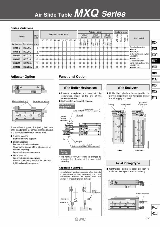
Series Variations
Locked
MXQ6L
MXQ8L
MXQ12L
MXQ16L
MXQ20L
MXQ25L
MXQ 6
MXQ 8
MXQ12
MXQ16
MXQ20
MXQ25
Standard type Symmetric type
Model
10 20 30 40 50 75 100 125 150
Rubberstopper
Shock absorber
Metalstopper
Adjuster optionStandard stroke (mm)
Auto switch
(mm)
6
8
12
16
20
25
Lock pistonSpring
Unlocked
Cylinder airsupply port
Speed controller
Functional OptionAdjuster Option
Air Slide Table MXQ Series
Bore size
Ext
ensi
onen
dR
etra
ctio
n en
dBo
th e
nds
Ext
ensi
onen
dR
etra
ctio
nen
dBo
th e
nds
Ext
ensi
onen
dR
etra
ctio
nen
dBo
th e
nds
Functional option
With
buf
fer
With
end l
ock
Axi
alpi
ping
type
Reed auto switch• D-A9• D-A9VSolid state auto switch• D-M9• D-M9V2-color indicator solid state auto switch• D-M9W• D-M9WV
Adjuster at extension end Retraction end adjuster
Rubber stopper Standard stroke adjuster
Shock absorber For use in harsh conditions. Absorbs the impact at the stroke end for smooth stopping. Improved stopping accuracy.
Metal stopper Improved stopping accuracy. Without cushioning function for use with light loads and low speeds.
Three different types of adjusting bolt have been standardized for front end rear and double end adjusters and cushion mechanisms.
Protects workpieces and tools, etc., by eliminating impact at the end of the extension stroke.
Buffer unit is auto switch capable.
Auto switchNormally OFF ∗ON is buffer in operation.( )
Bufferstroke
Magnet
Magnet
Auto switchNormally ON∗OFF is buffer in operation.( )
∗ The normally ON/OFF setting is changed by changing the direction of the auto switch mounting.
In workpiece insertion processes when there is a problem such as faulty positioning, the buffer mechanism absorbs the shock from the workpiece impact to prevent damage.
Air gripper
Workpiece
NG
Buffermechanism
Holds the cylinder’s home position to prevent dropping of the workpiece even if the air supply is cut off.
Centralized piping in axial direction to maintain clear space around the body.
217
MXH
MXS
MXQ
MXQ
MXF
MXW
MXJ
MXP
MXY
MTS
D-
-X
MXQ
Model Selection Step Formula/Data Selection Example
Operating Conditions
Kinetic Energy
Load Factor
3-1 Load Factor of Load Mass
3-2 Load Factor of the Static Moment
3-3 Load Factor of Dynamic Moment
3-4 Sum of the Load Factors
1
2
3
L2+A
5
L3
L1
MXQ Series
Model Selection
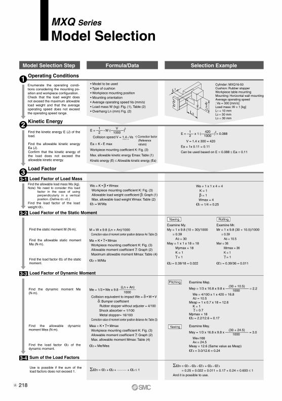
Enumerate the operating condi-tions considering the mounting po-sition and workpiece configuration.Check that the load weight does not exceed the maximum allowable load weight and that the average operating speed does not exceed the operating speed range.
• Model to be used• Type of cushion• Workpiece mounting position• Mounting orientation • Average operating speed Va (mm/s)• Load mass W (kg): Fig. (1), Table (2)• Overhang Ln (mm) Fig. (2)
Cylinder: MXQ16-50Cushion: Rubber stopperWorkpiece table mountingMounting: Horizontal wall mountingAverage operating speed: Va = 300 [mm/s]Load mass: W = 1 [kg]L1 = 10 mm L2 = 30 mm L3 = 30 mm
Find the kinetic energy E (J) of the load.
Find the allowable kinetic energy Ea (J).Confirm that the kinetic energy of the load does not exceed the allowable kinetic energy.
Ea = K • E max
1 V 2E = —— • W (————) 2 1000 Collision speed V = 1.4 • Va —— ∗
Workpiece mounting coefficient K: Fig. (3)
Max. allowable kinetic energy Emax: Table (1)
Kinetic energy (E) ≤ Allowable kinetic energy (Ea)
∗) Correction factor (Reference values)
1 420 2E = —— x 1 (————) = 0.088 2 1000
V = 1.4 x 300 = 420
Ea = 1x 0.11 = 0.11
Can be used based on E = 0.088 ≤ Ea = 0.11
Find the allowable load mass Wa (kg).Note) No need to consider this load
factor in the case of using perpendicularly in a vertical position. (Define α1 =0.)
Find the load factor of the load weight α1.
Wa = K • β • Wmax Workpiece mounting coefficient K: Fig. (3) Allowable load weight coefficient β: Graph (1) Max. allowable load weight Wmax: Table (2)α1 = W/Wa
Wa = 1 x 1 x 4 = 4 K = 1 β = 1 Wmax = 4α1 = 1/4 = 0.25
Find the static moment M (N·m).
Find the allowable static moment Ma (N·m).
Find the load factor α2 of the static moment.
M = W x 9.8 (Ln + An)/1000 Correction value of moment center position distance An: Table (3)
Ma = K • γ • Mmax Workpiece mounting coefficient K: Fig. (3) Allowable moment coefficient γ: Graph (2) Maximum allowable moment Mmax: Table (4)
α2 = M/Ma
Examine My.My = 1 x 9.8 (10 + 30)/1000 = 0.39 A3 = 30May = 1 x 1 x 18 = 18 Mymax = 18 K = 1 γ = 1
α2 = 0.39/18 = 0.022
RollingYawing
Examine Mr.Mr = 1 x 9.8 (30 + 10.5)/1000 = 0.39 A6 = 10.5Mar = 36 Mrmax = 36 K = 1 γ = 1
α'2 = 0.39/36 = 0.011
Find the dynamic moment Me (N·m).
Find the allowable dynamic moment Mea (N·m).
Find the load factor α3 of the dynamic moment.
(Ln + An)Me = 1/3 • We x 9.8 ————— 1000 Collision equivalent to impact We = δ • W • V δ: Bumper coefficient Rubber stopper without adjuster = 4/100 Shock absorber = 1/100 Metal stopper= 16/100 Correction value of moment center position distance An: Table (3)
Mea = K • γ • Mmax Workpiece mounting coefficient K: Fig. (3) Allowable moment coefficient γ: Graph (2) Max. allowable moment Mmax: Table (4)
α3 = Me/Mea
Examine Mep. (30 + 10.5)Mep = 1/3 x 16.8 x 9.8 x ——————— = 2.2 1000 We = 4/100 x 1 x 420 = 16.8 A2 = 10.5Meap = 1 x 0.7 x 18 = 12.6 K = 1 γ = 0.7Mpmax = 18α3 = 2.2/12.6 = 0.17
Examine Mey. (30 + 24.5)Mey = 1/3 x 16.8 x 9.8 x ——————— = 3.0 1000 We=168 A4 = 24.5Meay = 12.6 (Same value as Meap)α'3 = 3.0/12.6 = 0.24
Pitching
Yawing
Use is possible if the sum of the load factors does not exceed 1. Σαn = α1 + α2 + ·········· + αn ≤ 1
Σαn = α1 + α2 + α'2 + α3 + α'3 = 0.25 + 0.022 + 0.011 + 0.17 + 0.24 = 0.693 ≤ 1And it is possible to use.
218A
SymbolAn (n = 1 to 6)EEmaxLn (n = 1 to 3)M (Mp, My, Mr)Ma (Map, May, Mar)Me (Mep, Mey)Mea (Meap, Meay)Mmax (Mpmax, Mymax, Mrmax)V
DefinitionCorrection value of moment center position distanceKinetic energyAllowable kinetic energyOverhangStatic moment (Pitch, Yaw, Roll)Allowable static moment (Pitch, Yaw, Roll)Dynamic moment (Pitch, Yaw) Allowable dynamic moment (Pitch, Yaw) Maximum allowable moment (Pitch, Yaw, Roll)Collision speed
Symbol
MXQ 6MXQ 8MXQ12MXQ16MXQ20MXQ25
Model10 1.42.04.7
13 19 32
1.0
0.7
0.5
0.4
0.3
0.2
50 100 200 300 500 700
1.0
0.7
0.5
0.4
0.3
0.2
50 100 200 300 500 700
MXQ 6MXQ 8MXQ12MXQ16MXQ20MXQ25
Model
1014.516.521 27 29.535.5
Correction value of moment center position distance (Refer to Figure (2).)
MXQ 6MXQ 8MXQ12MXQ16MXQ20MXQ25
Model
0.612469
MXQ 6MXQ 8MXQ12MXQ16MXQ20MXQ25
ModelAllowable kinetic energy
Without adjusterRubber stopper
0.0180.0270.0550.11 0.16 0.24
Maximum allowable load mass
W
W
K = 1
K = 0.6
W
Mp
L1 A1
W
Mp
L1 A2
Mep
A2
L3
Mey
L2A
4
W
My
L2 A3
W
My
L2 A4
W
Mr
L3 A5
W
Mr
L3 A6
0.0180.0270.0550.11 0.16 0.24
Shock absorber—
0.0540.11 0.22 0.32 0.48
Metal stopper0.0090.0130.0270.0550.0800.12
Adjuster option
A1, A3
Stroke (mm) A2 A4 A5 A6
2014.516.521 27 29.535.5
3014.518.521 27 29.535.5
4018.520.525 27 29.535.5
5018.528 25 30 33.543
75—
28.534 33 37.543
100——
34 42.553.550
125———
42.555 64
150————
56.564
6 7 9
10.514 16.5
13.516 19.524.530 37
13.516 19.524.530 37
6 7 9
10.514 16.5
Stroke (mm)20 1.42.04.7
13 19 32
30 1.42.84.7
13 19 32
40 2.83.77.2
13 19 32
50 2.87.97.2
18 27 52
75 — 7.9
15 23 36 52
100——15428478
125———
42 84 140
150————
84 140
10 3.55.1
11 31 47 81
20 3.55.1
11 31 47 81
30 3.56.0
11 31 47 81
40 5.16.9
13 31 47 81
50 5.17.4
13 36 57
110
75 — 7.4
14 41 66
110
100—— 14 41 75130
125——— 41 75130
150———— 75130
Pitch/Yaw moment: Mpmax/MymaxStroke (mm)
Roll moment: Mrmax
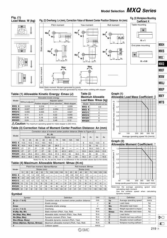
Caution The maximum operating speed for metal stopper is 200 mm/s.
Fig. (1) Load Mass: W (kg) Fig. (2) Overhang: Ln (mm), Correction Value of Moment Center Position Distance: An (mm)
Pitch moment Yaw moment Roll moment
Fig. (3) Workpiece Mounting Coefficient: K
Table mounting
End plate mounting
Sta
tic m
omen
tD
ynam
ic m
omen
t
Note) Static moment: Moment generated by gravity Dynamic moment: Moment generated by impact when colliding with stopper
Table (1) Allowable Kinetic Energy: Emax (J) Table (2)Maximum Allowable Load Mass: Wmax (kg)
Table (3) Correction Value of Moment Center Position Distance: An (mm)
Note) For A2, A4, A5 and A6, there is no difference in the corrected values due to the stroke.
Table (4) Maximum Allowable Moment: Mmax (N·m)
Unitmm
JJ
mmN·mN·mN·mN·mN·m
mm/s
SymbolVaWWaWeWmaxαβγK
DefinitionAverage operating speedLoad massAllowable load massWeight equivalent to impactMax. allowable load massLoad factorAllowable load mass coefficientAllowable moment coefficientWorkpiece mounting coefficient
Unitmm/s
kgkgkgkg————
Graph (1) Allowable Load Mass Coefficient: β
Allo
wab
le lo
ad m
ass
coef
ficie
nt: β
Average operating speed Va (mm/s)
Graph (2) Allowable Moment Coefficient: γ
Allo
wab
le m
omen
t coe
ffici
ent:
γ
Average operating speed Va (mm/s) Collision speed V (mm/s)
Note) Use the average operating speed when calculating static moment.Use the collision speed when calculating dynamic moment.
Model Selection MXQ Series
W
W
W
W
219
MXH
MXS
MXQ
MXQ
MXF
MXW
MXJ
MXP
MXY
MTS
D-
-X
MXQ
A
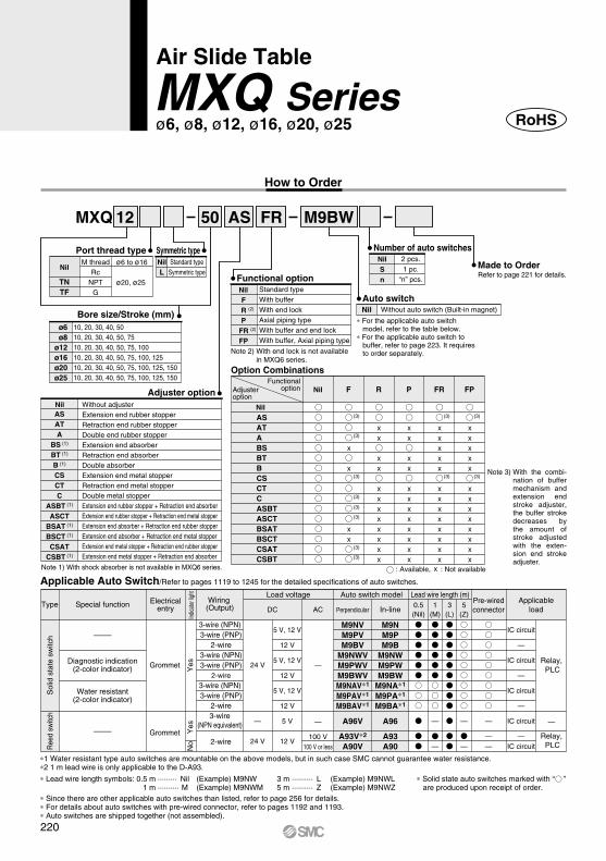
How to Order
ø6ø8
ø12ø16ø20ø25
MXQ 12 50 M9BWAS FR
NilL
Symmetric typePort thread type
Nil
TNTF
M threadRc
NPTG
ø6 to ø16
ø20, ø25
Without adjusterExtension end rubber stopperRetraction end rubber stopperDouble end rubber stopperExtension end absorberRetraction end absorberDouble absorberExtension end metal stopperRetraction end metal stopperDouble metal stopperExtension end rubber stopper + Retraction end absorberExtension end rubber stopper + Retraction end metal stopperExtension end absorber + Retraction end rubber stopperExtension end absorber + Retraction end metal stopperExtension end metal stopper + Retraction end rubber stopperExtension end metal stopper + Retraction end absorber
Nil
Refer to page 221 for details.
Nil
Nil F R P FR FP
Option Combinations
ASATABSBTBCSCTCASBTASCTBSATBSCTCSATCSBT
Functional option
A96V
A93V∗2
A90V
M9NVM9PVM9BV
M9NWVM9PWVM9BWVM9NAV∗1
M9PAV∗1
M9BAV∗1
A96
A93A90
M9NM9PM9B
M9NWM9PWM9BW
M9NA∗1
M9PA∗1
M9BA∗1
Type Special function
—
24 V
24 V
3-wire (NPN) 3-wire (PNP)
2-wire3-wire (NPN)3-wire (PNP)
2-wire3-wire (NPN) 3-wire (PNP)
2-wire
Load voltage
DC AC
Auto switch model Lead wire length (m)
Perpendicular In-line0.5(Nil)
5(Z)
—
100 V100 V or less
—
—
——
—
—
1(M)
—
—
IC circuit
—IC circuit
IC circuit
—
IC circuit
—
IC circuit
—
——
—
5 V
12 V
5 V, 12 V
12 V
5 V, 12 V
12 V
5 V, 12 V
12 V
3(L)
Standard typeSymmetric type
Bore size/Stroke (mm)10, 20, 30, 40, 5010, 20, 30, 40, 50, 7510, 20, 30, 40, 50, 75, 10010, 20, 30, 40, 50, 75, 100, 12510, 20, 30, 40, 50, 75, 100, 125, 15010, 20, 30, 40, 50, 75, 100, 125, 150
Adjuster option
ASATA
BS (1)
BT (1)
B (1)
CSCTC
ASBT (1)
ASCTBSAT (1)
BSCT (1)
CSATCSBT (1)
Note 1) With shock absorber is not available in MXQ6 series.
Number of auto switches2 pcs.1 pc.
“n” pcs.
NilSn
Made to Order
Auto switchNil Without auto switch (Built-in magnet)
∗ For the applicable auto switch model, refer to the table below.
∗ For the applicable auto switch to buffer, refer to page 223. It requires to order separately.
Standard typeWith bufferWith end lockAxial piping typeWith buffer and end lockWith buffer, Axial piping type
NilF
R (2)
P FR (2)
FP
Adjusteroption
Functionaloption
Note 3) With the combi-nation of buffer mechanism and extension end stroke adjuster, the buffer stroke decreases by the amount of stroke adjusted with the exten-sion end stroke adjuster.
: Available, : Not available
Applicable Auto Switch/Refer to pages 1119 to 1245 for the detailed specifications of auto switches.
Electricalentry
Ree
d sw
itch
Sol
id s
tate
sw
itch
Diagnostic indication(2-color indicator)
Water resistant(2-color indicator)
Grommet
Grommet Yes
No
Yes
Indic
ator
light
Wiring (Output)
3-wire(NPN equivalent)
2-wire
Pre-wiredconnector
Applicableload
Relay, PLC
Relay, PLC
∗ Lead wire length symbols: 0.5 m ········· Nil (Example) M9NW1 m ·········· M (Example) M9NWM
3 m ·········· L (Example) M9NWL5 m ·········· Z (Example) M9NWZ
∗1 Water resistant type auto switches are mountable on the above models, but in such case SMC cannot guarantee water resistance.∗2 1 m lead wire is only applicable to the D-A93.
∗ Solid state auto switches marked with “ ” are produced upon receipt of order.
∗ Since there are other applicable auto switches than listed, refer to page 256 for details.∗ For details about auto switches with pre-wired connector, refer to pages 1192 and 1193.∗ Auto switches are shipped together (not assembled).
Air Slide Table
MXQ Seriesø6, ø8, ø12, ø16, ø20, ø25
(3) (3) (3)
(3) (3)
(3)
(3)
(3)
(3)
(3)
(3)
(3)
RoHS
Note 2) With end lock is not available in MXQ6 series.
220
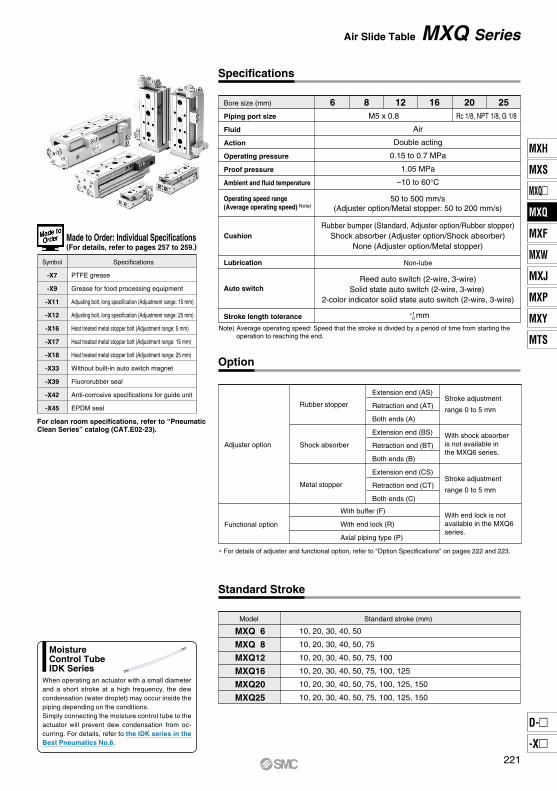
Bore size (mm)
Piping port size
Fluid
Action
Operating pressure
Proof pressure
Ambient and fluid temperature
Specifications
Air
Double acting
0.15 to 0.7 MPa
1.05 MPa
–10 to 60°C
50 to 500 mm/s(Adjuster option/Metal stopper: 50 to 200 mm/s)
Rubber bumper (Standard, Adjuster option/Rubber stopper)Shock absorber (Adjuster option/Shock absorber)
None (Adjuster option/Metal stopper)
Non-lube
Reed auto switch (2-wire, 3-wire)Solid state auto switch (2-wire, 3-wire)
2-color indicator solid state auto switch (2-wire, 3-wire)
mm
M5 x 0.8
Operating speed range (Average operating speed) Note)
MXQ 6
MXQ 8
MXQ12
MXQ16
MXQ20
MXQ25
Standard Stroke
Standard stroke (mm)
10, 20, 30, 40, 50
10, 20, 30, 40, 50, 75
10, 20, 30, 40, 50, 75, 100
10, 20, 30, 40, 50, 75, 100, 125
10, 20, 30, 40, 50, 75, 100, 125, 150
10, 20, 30, 40, 50, 75, 100, 125, 150
Cushion
Lubrication
Auto switch
Stroke length tolerance
6 8 12 16 20 25Rc 1/8, NPT 1/8, G 1/8
Adjuster option
Option
Extension end (AS)
Retraction end (AT)
Both ends (A)
Extension end (BS)
Retraction end (BT)
Both ends (B)
Extension end (CS)
Retraction end (CT)
Both ends (C)
Rubber stopper
Shock absorber
Metal stopper
Functional option
With buffer (F)
With end lock (R)
Axial piping type (P)
Stroke adjustment
range 0 to 5 mm
With shock absorber is not available in the MXQ6 series.
Stroke adjustment
range 0 to 5 mm
With end lock is not available in the MXQ6 series.
Model
Symbol Specifications
PTFE grease
Grease for food processing equipment
Adjusting bolt, long specification (Adjustment range: 15 mm)
Adjusting bolt, long specification (Adjustment range: 25 mm)
Heat treated metal stopper bolt (Adjustment range: 5 mm)
Heat treated metal stopper bolt (Adjustment range: 15 mm)
Heat treated metal stopper bolt (Adjustment range: 25 mm)
Without built-in auto switch magnet
Fluororubber seal
Anti-corrosive specifications for guide unit
EPDM seal
-X7
-X9
-X11
-X12
-X16
-X17
-X18
-X33
-X39
-X42
-X45
+1 0
Made to Order: Individual Specifications(For details, refer to pages 257 to 259.)
For clean room specifications, refer to “Pneumatic Clean Series” catalog (CAT.E02-23).
∗ For details of adjuster and functional option, refer to “Option Specifications” on pages 222 and 223.
Air Slide Table MXQ Series
Note) Average operating speed: Speed that the stroke is divided by a period of time from starting the operation to reaching the end.
MoistureControl TubeIDK Series
When operating an actuator with a small diameter and a short stroke at a high frequency, the dew condensation (water droplet) may occur inside the piping depending on the conditions.Simply connecting the moisture control tube to the actuator will prevent dew condensation from oc-curring. For details, refer to the IDK series in the Best Pneumatics No.6.
221
MXH
MXS
MXQ
MXQ
MXF
MXW
MXJ
MXP
MXY
MTS
D-
-X
MXQ

Symmetric type
Adjustment rangeNil
-X11-X12
MXQ
5 mm15 mm25 mm
6812162025
12 X11AS
Standard
Semi-standard
ø6ø8
ø12ø16ø20ø25
Theoretical Output
0.2
11
8
20
15
45
34
80
60
126
94
196
151
Bore size (mm)
Rod size(mm)
Piston area(mm2)
Operating direction
Operating pressure (MPa)
6
8
12
16
3
4
6
8
OUT
IN
57
42
OUT
IN
101
75
OUT
IN
226
170
OUT
IN
402
302
0.3
17
13
30
23
68
51
121
91
188
141
295
227
0.4
23
17
40
30
90
68
161
121
251
188
393
302
0.5
29
21
51
38
113
85
201
151
314
236
491
378
0.6
34
25
61
45
136
102
241
181
377
283
589
454
0.7
40
29
71
53
158
119
281
211
440
330
687
529
MXQ 6MXQ 8MXQ12MXQ16MXQ20MXQ25
Model
Standard stroke (mm)
20 10
25 12
OUT
IN
628
471
OUT
IN
982
756
INOUT
Additional weight of adjuster option
10
100
140
335
595
1085
1725
20
120
170
340
600
1085
1725
30
140
210
380
660
1085
1725
40
180
250
450
725
1180
1925
50
200
315
480
820
1380
2370
75
—
385
645
980
1720
2715
100
—
—
735
1240
2310
3395
125
—
—
—
1390
2600
4235
150
—
—
—
—
2890
4680
6
10
25
45
80
130
5
10
23
40
65
110
25
35
70
105
130
200
—
40
100
160
310
560
How to Order Stroke Adjuster (Accessory)
Weight
L
NilL
ASATBSBTCSCT
Stroke adjustment range
Option Specifications
—
30
47
75
170
220
—
23
30
53
120
140
10
23
35
60
115
180
5
10
23
40
65
110
The dual rod ensures an output twice that of current cylinders. (N)
Note) Theoretical output (N) = Pressure (MPa) x Piston area (mm2)
Rubber stopper
Extension end Retraction end
Shock absorber
Extension end Retraction end
Metal stopper
Extension end Retraction end
(g)
Axial piping type(S: Stroke (mm))
With end lock
With buffer
Extra for option
13 + 0.2 S
26 + 0.2 S
43 + 0.2 S
55 + 0.2 S
166 + 0.5 S
240 + 0.5 S
Stroke Adjustment Range of Adjuster Option (Identical for extension and retraction ends)
Type
Rubber stopper
With shock absorber
Metal stopper
0 to 5 mm
Refer to the dimensions on page 252.
0 to 5 mm
∗ Optional wide adjustment range adjuster are available with rubber stopper and metal stopper.
Adjuster optionExtension endRetraction endExtension endRetraction endExtension endRetraction end
Rubberstopper
Shock absorber
Metalstopper
Standard typeSymmetric type
Applicable bore sizeNote 1) -X12 (adjusting range: 25 mm) is not available in the MXQ6 series.Note 2) -X11 and -X12 are not available with shock absorber.Note 3) With Shock absorber is not available in the MXQ6 series.Note 4) For dimensions, refer to pages 250 to 254. For the symmetric type, refer to the external dimensions symmetrically. (Symmetric type is what the direction of the adjusting bolt is reversed.)
MXQ Series
222

Table Accuracy
MXQ6
Shock Absorber Specifications
Model MXQ6
6
3
6
MXQ8
8
5
8
MXQ12
12
10
13
MXQ16
16
13
17
MXQ20
20
17
25
MXQ25
25
21
29
5 10
Model MXQ8
8
25
MXQ12
12
60
MXQ16
16
110
MXQ20
20
160
MXQ25
25
250
50 to 500 mm/s
RB0805
MXQ8
0.98
5
80
245
1.96
3.83
15
RB0806
MXQ12
RB1007
MXQ16
RB1411
MXQ20
RB1412
MXQ25
2.94
6
80
245
1.96
4.22
15
5.88
7
50 to 500
70
422
–10 to 60
4.22
6.86
25
14.7
11
45
814
6.86
15.30
65
19.6
12
45
814
6.86
15.98
65
With End Lock Specifications
Buffer Mechanism Specifications
Applicable Auto Switch to Buffer
–4 to 0
MXQ8
–4 to 0
MXQ12
–6 to 0
MXQ16
–10 to 0
MXQ20
–12 to 0
MXQ25
–14 to 0
MXQ 6
MXQ 8
MXQ12
MXQ16
MXQ20
MXQ25
10
0.025
0.025
0.03
0.035
0.04
0.045
20
0.03
0.03
0.03
0.035
0.04
0.045
30
0.035
0.035
0.035
0.04
0.04
0.045
40
0.04
0.04
0.04
0.045
0.045
0.05
50
0.045
0.055
0.045
0.05
0.055
0.06
75
—
0.065
0.065
0.065
0.07
0.07
100
—
—
0.075
0.08
0.095
0.09
125
—
—
—
0.095
0.105
0.115
150
—
—
—
—
0.125
0.125
0.06
0.04
0.02
0 50 100 150
Shock absorber model
Applicable slide table
Max. energy absorption (J)
Stroke absorption (mm)
Max. collision speed (mm/s)
Max. operating frequency (cycle/min)
Max. allowable thrust (N)
Ambient temperature range (°C)
Spring force (N)
Weight (g)
Extended
Retracted
Note) The shock absorber service life is different from that of the MXQ cylinder depending on operating conditions. Refer to the RB Series Specific Product Precautions for the replacement period.
Bore size (mm)
Piston speed
Holding force (N)
Note) For caution on end lock, refer to page 263.
Bore size (mm)
Piston speed
Buffer stroke (mm)
Bufferstrokeload (N)
Strokeat 0 (mm)Maximumstroke
50 to 500 mm/s (Horizontal mounting 50 to 300 mm/s)
Note 1) For caution on handling the one with buffer mechanism, refer to page 263.
Note 2) The buffer stroke decreases by the amount of stroke adjusted with the extension end stroke adjuster.
Type model
D-M9BV
D-M9NV
D-M9PV
Solid state switch
Specifications
With light, 2-wire
With light, 3-wire, Output: NPN
With light, 3-wire, Output: PNP
Electrical entry direction
Vertical
∗ The auto switch for buffer must be ordered separately.
Model
B side parallelism to A side
B side traveling parallelism to A side
C side perpendicularity to A side
M dimension tolerance
W dimension tolerance
Radial internal clearance (µm)
Refer to Table (1).
Refer to Graph (1).
0.05 mm
±0.08 mm (±0.1 mm) ∗1
±0.1 mm
∗1) ±0.1 mm for 75 mm or longer stroke
Table (1) B Side Parallelism to A Side (mm)
(mm)
ModelStroke (mm)
Graph (1) B Side Traveling Parallelism to A Side
Tra
velin
g pa
ralle
lism
(m
m)
Stroke (mm)
Traveling parallelism:The amount of deflection on a dial gauge when the table travels a full stroke with the body secured on a reference base surface.
CB
A
Radialclearance
M
W
Air Slide Table MXQ Series
223
MXH
MXS
MXQ
MXQ
MXF
MXW
MXJ
MXP
MXY
MTS
D-
-X
MXQ
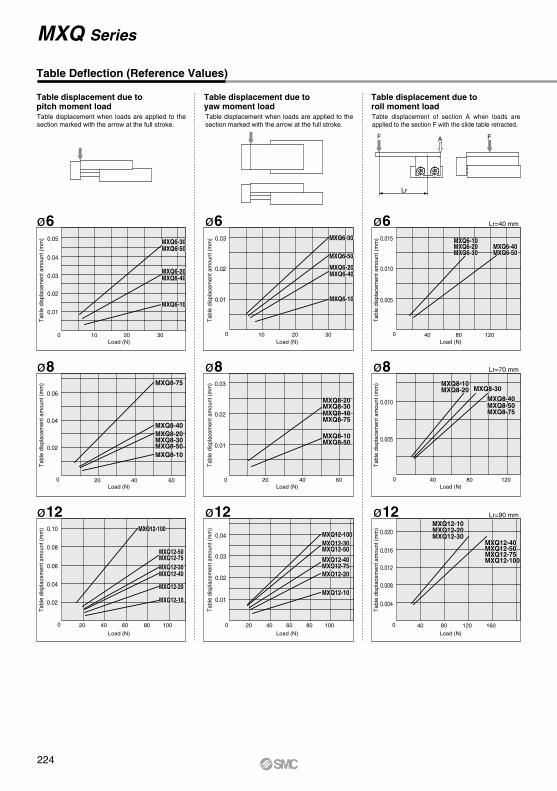
Table Deflection (Reference Values)
Lr=40 mm
Lr=70 mm
Lr=90 mm
0.03
0.02
0.01
10 20 30
20 40 60
0.03
0.02
0.01
20 40 60 80 100
0.01
0.02
0.03
0.04
0.03
0.02
0.01
10 20 30
0.04
0.02
20 40 60
0.04
0.06
20 40 60 80 100
0.10
0.02
0.04
0.06
0.08
0.015
0.010
40 80 120
0.005
0.010
40 80 120
0.005
0.012
0.008
120
0.016
0.004
0.020
16040 80
0
0
0
0
0
0
0
0
0
ø8
ø12
ø6
ø8
ø12
ø6
ø8
ø12
F A
Lr
F
MXQ6-10
MXQ6-20
MXQ6-30MXQ6-50
MXQ6-40
MXQ6-10
MXQ6-20
MXQ6-30MXQ6-50
MXQ6-40
MXQ6-10
MXQ6-20
MXQ6-30
MXQ6-50
MXQ6-40
MXQ6-10
MXQ6-20
MXQ6-30
MXQ6-50
MXQ6-40
MXQ6-10MXQ6-20MXQ6-30 MXQ6-50
MXQ6-40MXQ6-10MXQ6-20MXQ6-30 MXQ6-50
MXQ6-40
MXQ12-10
MXQ12-30
MXQ12-20
MXQ12-50
MXQ12-40
MXQ12-75
MXQ12-100
MXQ12-10
MXQ12-30
MXQ12-20
MXQ12-50
MXQ12-40
MXQ12-75
MXQ12-100
MXQ12-75
MXQ12-10
MXQ12-40
MXQ12-20
MXQ12-30MXQ12-100
MXQ12-50
MXQ12-75
MXQ12-10
MXQ12-40
MXQ12-20
MXQ12-30MXQ12-100
MXQ12-50
MXQ12-100MXQ12-75MXQ12-50MXQ12-40
MXQ12-30MXQ12-20MXQ12-10
MXQ12-100MXQ12-75MXQ12-50MXQ12-40
MXQ12-30MXQ12-20MXQ12-10
MXQ8-20
MXQ8-10
MXQ8-30MXQ8-40
MXQ8-50
MXQ8-75
MXQ8-20
MXQ8-10
MXQ8-30MXQ8-40
MXQ8-50
MXQ8-75MXQ8-75
MXQ8-10MXQ8-20 MXQ8-30
MXQ8-50MXQ8-40
MXQ8-75
MXQ8-10MXQ8-20 MXQ8-30
MXQ8-50MXQ8-40
ø60.05
MXQ8-10
MXQ8-30
MXQ8-75
MXQ8-20MXQ8-40
MXQ8-50MXQ8-10
MXQ8-30
MXQ8-75
MXQ8-20MXQ8-40
MXQ8-50
Table displacement due topitch moment loadTable displacement when loads are applied to the section marked with the arrow at the full stroke.
Table displacement due toyaw moment loadTable displacement when loads are applied to the section marked with the arrow at the full stroke.
Table displacement due toroll moment loadTable displacement of section A when loads are applied to the section F with the slide table retracted.
Tab
le d
ispl
acem
ent a
mou
nt (
mm
)
Tab
le d
ispl
acem
ent a
mou
nt (
mm
)
Tab
le d
ispl
acem
ent a
mou
nt (
mm
)
Tab
le d
ispl
acem
ent a
mou
nt (
mm
)
Tab
le d
ispl
acem
ent a
mou
nt (
mm
)
Tab
le d
ispl
acem
ent a
mou
nt (
mm
)
Tab
le d
ispl
acem
ent a
mou
nt (
mm
)
Tab
le d
ispl
acem
ent a
mou
nt (
mm
)
Tab
le d
ispl
acem
ent a
mou
nt (
mm
)
Load (N) Load (N) Load (N)
Load (N) Load (N) Load (N)
Load (N) Load (N) Load (N)
MXQ Series
224
Lr=120 mm
Lr=160 mm
Lr=200 mm
0.06
0.04
0.02
50 100 200
100 200 300
0.06
0.04
0.02
100 200 300 400 500
0.04
0.06
0.08
0.10
0.08
0.04
50 100 200
0.04
100 200 300
0.08
0.12
100 200 300 400 500
0.12
0.04
0.08
0.04
0.03
100 200 300
0.02
0.04
100 200 300
0.02
0.04
0.02
600
0.06
0.08
800200 400
0
0
0
0
0
0
0
0
0
ø20
ø25
ø16
ø20
ø25
ø16
ø20
ø25
ø160.12
F A
Lr
F
MXQ16-100MXQ16-125
MXQ16-75MXQ16-20MXQ16-30
MXQ16-10
MXQ16-40
MXQ16-50
MXQ16-100MXQ16-125
MXQ16-75MXQ16-20MXQ16-30
MXQ16-10
MXQ16-40
MXQ16-50
MXQ25-100MXQ25-125MXQ25-150
MXQ25- 50MXQ25- 75
MXQ25- 10MXQ25- 20MXQ25- 30MXQ25- 40 MXQ25-100
MXQ25-125MXQ25-150
MXQ25- 50MXQ25- 75
MXQ25- 10MXQ25- 20MXQ25- 30MXQ25- 40
MXQ16-30
MXQ16-50
MXQ16-20
MXQ16-10
MXQ16-40
MXQ16-75MXQ16-100MXQ16-125
MXQ16-30
MXQ16-50
MXQ16-20
MXQ16-10
MXQ16-40
MXQ16-75MXQ16-100MXQ16-125
MXQ16-10
MXQ16-20
MXQ16-100MXQ16-30
MXQ16-50
MXQ16-75MXQ16-40
MXQ16-125
MXQ16-10
MXQ16-20
MXQ16-100MXQ16-30
MXQ16-50
MXQ16-75MXQ16-40
MXQ16-125
MXQ20-10
MXQ20-50
MXQ20-125
MXQ20-20
MXQ20-75MXQ20-30
MXQ20-150
MXQ20-40
MXQ20-100
MXQ20-10
MXQ20-50
MXQ20-125
MXQ20-20
MXQ20-75MXQ20-30
MXQ20-150
MXQ20-40
MXQ20-100
MXQ25-10
MXQ25-30MXQ25-50MXQ25-125
MXQ25-150MXQ25-100
MXQ25-75
MXQ25-20
MXQ25-40
MXQ25-10
MXQ25-30MXQ25-50MXQ25-125
MXQ25-150MXQ25-100
MXQ25-75
MXQ25-20
MXQ25-40
MXQ25-10
MXQ20-125MXQ20-150
MXQ20-50
MXQ20-10
MXQ20-30
MXQ20-20
MXQ20-100
MXQ20-40MXQ20-75
MXQ20-125MXQ20-150
MXQ20-50
MXQ20-10
MXQ20-30
MXQ20-20
MXQ20-100
MXQ20-40MXQ20-75
150 150
0.01
400
0.06
400 500 600
0.08
MXQ25-125MXQ25-100MXQ25-75
MXQ25-150
MXQ25-50
MXQ25-20
MXQ25-40
MXQ25-30MXQ25-125MXQ25-100MXQ25-75
MXQ25-150
MXQ25-50
MXQ25-20
MXQ25-40
MXQ25-30
0.02
MXQ20-100MXQ20-125MXQ20-150
MXQ20-10MXQ20-20MXQ20-30
MXQ20-50MXQ20-75
MXQ20-40 MXQ20-100MXQ20-125MXQ20-150
MXQ20-10MXQ20-20MXQ20-30
MXQ20-50MXQ20-75
MXQ20-40
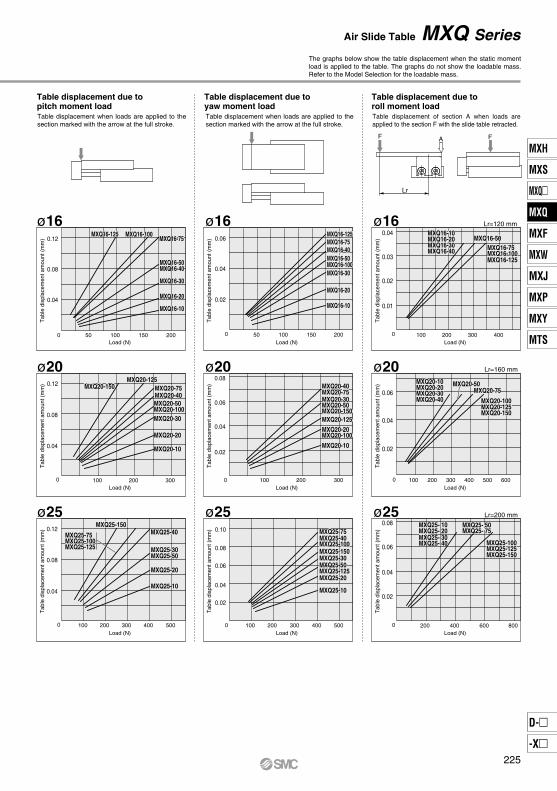
The graphs below show the table displacement when the static moment load is applied to the table. The graphs do not show the loadable mass. Refer to the Model Selection for the loadable mass.
Table displacement due topitch moment loadTable displacement when loads are applied to the section marked with the arrow at the full stroke.
Table displacement due toyaw moment loadTable displacement when loads are applied to the section marked with the arrow at the full stroke.
Table displacement due toroll moment loadTable displacement of section A when loads are applied to the section F with the slide table retracted.
Tab
le d
ispl
acem
ent a
mou
nt (
mm
)
Load (N)
Tab
le d
ispl
acem
ent a
mou
nt (
mm
)
Load (N)
Tab
le d
ispl
acem
ent a
mou
nt (
mm
)
Load (N)
Tab
le d
ispl
acem
ent a
mou
nt (
mm
)
Load (N)
Tab
le d
ispl
acem
ent a
mou
nt (
mm
)
Load (N)
Tab
le d
ispl
acem
ent a
mou
nt (
mm
)
Load (N)
Tab
le d
ispl
acem
ent a
mou
nt (
mm
)
Load (N)
Tab
le d
ispl
acem
ent a
mou
nt (
mm
)
Load (N)
Tab
le d
ispl
acem
ent a
mou
nt (
mm
)
Load (N)
Air Slide Table MXQ Series
225
MXH
MXS
MXQ
MXQ
MXF
MXW
MXJ
MXP
MXY
MTS
D-
-X
MXQ
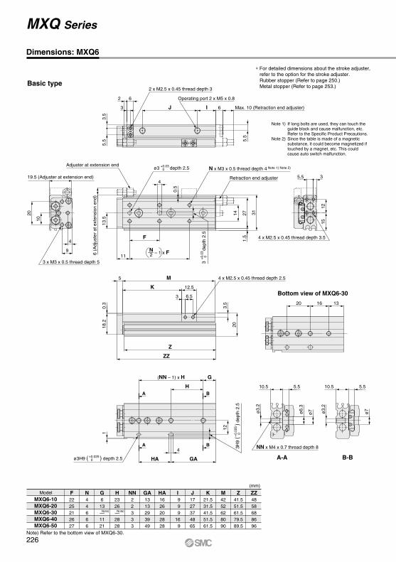
Dimensions: MXQ6
Model F2225212627
N44666
G6
13—1121
H2326—2828
NN22333
I 9 9 916 9
J1727374865
K21.531.541.551.561.5
Z41.551.561.579.589.5
M4252628090
ZZ4858688696
MXQ6-10MXQ6-20MXQ6-30MXQ6-40MXQ6-50
Basic type
(mm)
GA1313293949
HA1626202828
∗ For detailed dimensions about the stroke adjuster, refer to the option for the stroke adjuster.Rubber stopper (Refer to page 250.)Metal stopper (Refer to page 253.)
Note 1) If long bolts are used, they can touch the guide block and cause malfunction, etc.
Refer to the Specific Product Precautions.Note 2) Since the table is made of a magnetic
substance, it could become magnetized if touched by a magnet, etc. This could cause auto switch malfunction.
Note)Note)
Note) Refer to the bottom view of MXQ6-30.
4 x M2.5 x 0.45 thread depth 3.5
Bottom view of MXQ6-30
B
B
A
A
ø3H9 ( ) depth 2.5+0.0250
ø3 depth 2.5+0.030
Operating port 2 x M5 x 0.8
2 x M2.5 x 0.45 thread depth 3
3 x M3 x 0.5 thread depth 5
NN x M4 x 0.7 thread depth 8
A-A
4 x M2.5 x 0.45 thread depth 2.5
1512
35.5
B-B
Adjuster at extension end
Retraction end adjuster
ø7
10.5
ø3.
2
5.5
20 16 13
4
HA GA
H
G(NN – 1) x H
5 M
ZZ
Z
0.3
18.2
20
11
3
d
epth
2.5
+0.
030
4
F
13.5
3.5
5.5
3 IJ
5.5
4
9
20
10
ø7
10.5 5.5
ø3.
2
2 6
0.5
1.5
14 27 31
3 6.5
12.5K
3.5
1
12
6 (A
djus
ter
at e
xten
sion
end
)
Max. 10 (Retraction end adjuster)6
19.5 (Adjuster at extension end)
ø6.
3
N x M3 x 0.5 thread depth 4 Note 1) Note 2)
2N – 1 x F
3H9
(
)
dept
h 2.
5+
0.02
50
MXQ Series
226

With buffer (ø6): MXQ6-F
∗ Other dimensions are the same as basic type.
Axial piping type (ø6): MXQ6-P
∗ Other dimensions are the same as basic type.
3 x M3 x 0.5 thread depth 5
28
0.3
19.2
22
8
1630
4
8
Operating port 2 x M5 x 0.8
12.5
12
6.3
26
12
5.5
Air Slide Table MXQ Series
227
MXH
MXS
MXQ
MXQ
MXF
MXW
MXJ
MXP
MXY
MTS
D-
-X
MXQ
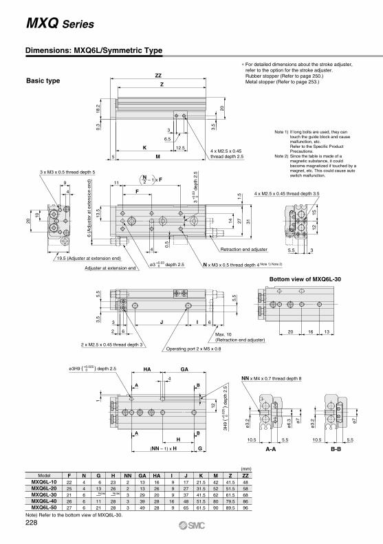
Dimensions: MXQ6L/Symmetric Type
Model F2225212627
N44666
G 613—1121
H2326—2828
NN22333
I 9 9 916 9
J1727374865
K21.531.541.551.561.5
Z41.551.561.579.589.5
M4252628090
ZZ4858688696
MXQ6L-10MXQ6L-20MXQ6L-30MXQ6L-40MXQ6L-50
Basic type
(mm)
GA1313293949
HA1626202828
∗ For detailed dimensions about the stroke adjuster, refer to the option for the stroke adjuster.Rubber stopper (Refer to page 250.)Metal stopper (Refer to page 253.)
Note 1) If long bolts are used, they can touch the guide block and cause malfunction, etc.
Refer to the Specific Product Precautions.
Note 2) Since the table is made of a magnetic substance, it could become magnetized if touched by a magnet, etc. This could cause auto switch malfunction.
Bottom view of MXQ6L-30
B
B
A
A
N x M3 x 0.5 thread depth 4 Note 1) Note 2)
Operating port 2 x M5 x 0.82 x M2.5 x 0.45 thread depth 3
NN x M4 x 0.7 thread depth 8
A-A
4 x M2.5 x 0.45 thread depth 2.5
B-B
Retraction end adjuster
Adjuster at extension end
3 x M3 x 0.5 thread depth 5
4 x M2.5 x 0.45 thread depth 3.5
ø7
10.5
ø3.
2
5.5
20 16 13
4
HA GA
H
G (NN – 1) x H
5 M
ZZ
Z
0.3
18.2 20
4
F
3.5
5.5
3 IJ
5.5
ø7
10.5 5.5
ø3.
2
2 6
0.5
1.5
14 27 31
3
6.5
12.5K
3.5
1
12
6 (A
djus
ter
at e
xten
sion
end
)
Max. 10(Retraction end adjuster)
6
11
13.5
4
9
20
10
ø6.
3
3
d
epth
2.5
+0.
030
19.5 (Adjuster at extension end)
2N – 1 x F
ø3 depth 2.5+0.030
Note) Note)
ø3H9 ( ) depth 2.5+0.0250
3H9
(
)
dept
h 2.
5+
0.02
50
MXQ Series
1512
35.5
Note) Refer to the bottom view of MXQ6L-30.
228
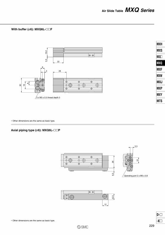
∗ Other dimensions are the same as basic type.
With buffer (ø6): MXQ6L-F
∗ Other dimensions are the same as basic type.
3 x M3 x 0.5 thread depth 5
28
0.3
19.2
22
8
1630
4
8
Operating port 2 x M5 x 0.8
12.5
12
6.3
26
12
5.5
Axial piping type (ø6): MXQ6L-P
Air Slide Table MXQ Series
229
MXH
MXS
MXQ
MXQ
MXF
MXW
MXJ
MXP
MXY
MTS
D-
-X
MXQ

Dimensions: MXQ8
Model F252526324650
N446666
G 714— 8 831
H2528—312930
NN223344
I111012141312
J 1728405278
105
K23.533.543.553.563.588.5
Z 45.5 55.5 69.5 83.5108.5134.5
M 46 56 70 84109135
ZZ 53 63 77 91116142
MXQ8-10MXQ8-20MXQ8-30MXQ8-40MXQ8-50MXQ8-75
Basic type
(mm)
GA131429393761
HA192827315860
NA444488
KA————
82.5112.5
∗ For detailed dimensions about the stroke adjuster, refer to the option for the stroke adjuster.Rubber stopper (Refer to page 250.)Metal stopper (Refer to page 253.)
Note 1) If long bolts are used, they can touch the guide block and cause malfunction, etc.
Refer to the Specific Product Precautions.Note 2) Since the table is made of a magnetic
substance, it could become magnetized if touched by a magnet, etc. This could cause auto switch malfunction.
Note) Refer to the bottom view of MXQ8-30.
Note) Note)
NN x M4 x 0.7 thread depth 8
A-A B-B
B
BA
A
2 x M3 x 0.5 thread depth 4 Operating port 2 x M5 x 0.8
N x M3 x 0.5 thread depth 4.5 Note 1) Note 2)
3 x M4 x 0.7 thread depth 6
Bottom view of MXQ8-30
NA x M3 x 0.5 thread depth 3.5
Adjuster at extension end
Retraction end adjuster
ø3.
2
ø7
12.512.5
ø3.
2
ø6.
5
ø7
5.7 5.7
ZZ
Z
6 M
23
0.3
21.2
4
14
H
G
HA GA
(NN – 1) x H
0.7
12
F
46.
53.5 IJ
6.5
4
16
24
5
10
12
27 23 6
2 7
16 321
36
3.8 7
14.6K
3.8 7
14.6KA
4
18 Max. 11 (Retraction end adjuster)
22.5 (Adjuster at extension end)
6.5
(Adj
uste
r at
ext
ensi
on e
nd)
ø3 depth 3+0.030
3
d
epth
3+
0.03
04 x M3 x 0.5 thread depth 4
2N – 1 x F
ø3H9 ( ) depth 3+0.0250
3H9
(
)
dept
h 3
+0.
025
0
MXQ Series
6.5 3.5
1715
230
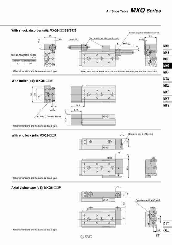
Extension end20
Retraction end20
Stroke Adjustable Range(mm)
∗ Other dimensions are the same as basic type. Note) Note that the top of the shock absorber unit will be higher than that of the table.
With buffer (ø8): MXQ8-F
∗ Other dimensions are the same as basic type.
With end lock (ø8): MXQ8-R
∗ Other dimensions are the same as basic type.
Axial piping type (ø8): MXQ8-P
∗ Other dimensions are the same as basic type.
Shock absorber at extension end
Shock absorber at retraction end
25
2 Note)11
.5 Max. 23
8 Max. 32
1
2 Note) 25
3 x M4 x 0.7 thread depth 6
28.5
0.3
22.2
22.5
12
2434
5
10
Operating port 2 x M5 x 0.8
17.5
4
340
.5
16
Operating port 2 x M5 x 0.8
15
6.5
316.
314
12
14.5
With shock absorber (ø8): MXQ8-BS/BT/B
Air Slide Table MXQ Series
231
MXH
MXS
MXQ
MXQ
MXF
MXW
MXJ
MXP
MXY
MTS
D-
-X
MXQ
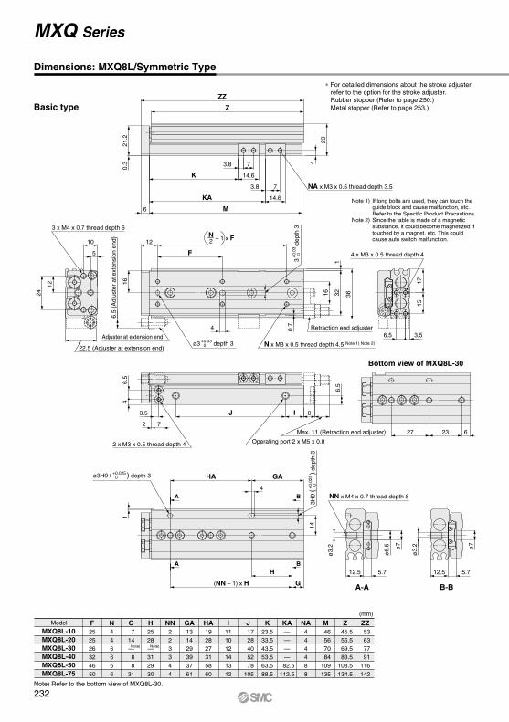
Dimensions: MXQ8L/Symmetric Type
Model F252526324650
N446666
G 714— 8 831
H2528—312930
NN223344
I111012141312
J 1728405278
105
K23.533.543.553.563.588.5
Z 45.5 55.5 69.5 83.5108.5134.5
M 46 56 70 84109135
ZZ 53 63 77 91116142
MXQ8L-10MXQ8L-20MXQ8L-30MXQ8L-40MXQ8L-50MXQ8L-75
Basic type
(mm)
GA131429393761
HA192827315860
NA444488
KA————
82.5112.5
∗ For detailed dimensions about the stroke adjuster, refer to the option for the stroke adjuster.Rubber stopper (Refer to page 250.)Metal stopper (Refer to page 253.)
Note 1) If long bolts are used, they can touch the guide block and cause malfunction, etc.
Refer to the Specific Product Precautions.Note 2) Since the table is made of a magnetic
substance, it could become magnetized if touched by a magnet, etc. This could cause auto switch malfunction.
Note)Note)
Note) Refer to the bottom view of MXQ8L-30.
NN x M4 x 0.7 thread depth 8
A-A B-B
B
BA
A
2 x M3 x 0.5 thread depth 4 Operating port 2 x M5 x 0.8
N x M3 x 0.5 thread depth 4.5 Note 1) Note 2)
3 x M4 x 0.7 thread depth 6
Bottom view of MXQ8L-30
NA x M3 x 0.5 thread depth 3.5
Adjuster at extension end
Retraction end adjuster
ø3.
2 ø7
12.512.5
ø3.
2
ø6.
5 ø7
5.7 5.7
ZZ
Z
6 M
23
0.3
21.2
4
14
H
G
HA GA
(NN – 1) x H
0.7
12
F
46.
5
3.5 IJ
6.5
4
16
24
5
10
12
27 23 62 7
16 321
36
3.8 7
14.6K
3.8 7
14.6KA
4
1
8
Max. 11 (Retraction end adjuster)
22.5 (Adjuster at extension end)
6.5
(Adj
uste
r at
ext
ensi
on e
nd)
3
d
epth
3+
0.03
0 4 x M3 x 0.5 thread depth 4
2N – 1 x F
ø3 depth 3+0.030
ø3H9 ( ) depth 3+0.0250
3H9
(
)
dept
h 3
+0.
025
0
MXQ Series
6.5 3.5
1715
232

Extension end20
Retraction end20
Axial piping type (ø8): MXQ8L-P
Stroke Adjustable Range(mm)
∗ Other dimensions are the same as basic type. Note) Note that the top of the shock absorber unit will be higher than that of the table.
∗ Other dimensions are the same as basic type.
∗ Other dimensions are the same as basic type.
∗ Other dimensions are the same as basic type.
Shock absorber at extension end
Shock absorber at retraction end
25
2 Note)
11.5 Max. 23
8 Max. 32 1
2 Note)
25
3 x M4 x 0.7 thread depth 6
28.5
0.3
22.2
22.5
2434
5
10
12
Operating port 2 x M5 x 0.8
17.5
4
340
.5
16
Operating port 2 x M5 x 0.8
15
6.5
316.
314
12
14.5
With shock absorber (ø8): MXQ8L-BS/BT/B
With buffer (ø8): MXQ8L-F
With end lock (ø8): MXQ8L-R
Air Slide Table MXQ Series
233
MXH
MXS
MXQ
MXQ
MXF
MXW
MXJ
MXP
MXY
MTS
D-
-X
MXQ
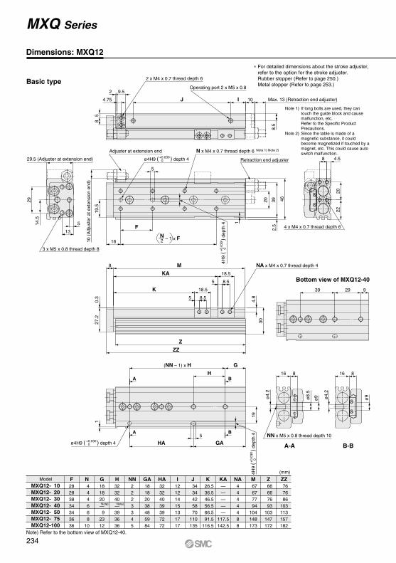
Dimensions: MXQ12
Model F28283834343636
N 4 4 4 6 6 810
G181820— 92312
H323240—393636
NN2223345
I12121415131717
J 3434425870
110135
K 26.5 36.5 46.5 56.5 66.5 91.5116.5
Z 66 66 76 93103147172
M 67 67 77 94104148173
ZZ 76 76 86103113157182
MXQ12- 10MXQ12- 20MXQ12- 30MXQ12- 40MXQ12- 50MXQ12- 75MXQ12-100
(mm)
GA18182038485984
HA32324039397272
NA4444488
KA—————
117.5142.5
Basic type
∗ For detailed dimensions about the stroke adjuster, refer to the option for the stroke adjuster.Rubber stopper (Refer to page 250.)Metal stopper (Refer to page 253.)
Note 1) If long bolts are used, they can touch the guide block and cause malfunction, etc.
Refer to the Specific Product Precautions.
Note 2) Since the table is made of a magnetic substance, it could become magnetized if touched by a magnet, etc. This could cause auto switch malfunction.
Note)Note)
Note) Refer to the bottom view of MXQ12-40.
B-BA-A
NN x M5 x 0.8 thread depth 10A
A
B
B
3 x M5 x 0.8 thread depth 8
Operating port 2 x M5 x 0.8
2 x M4 x 0.7 thread depth 6
N x M4 x 0.7 thread depth 6 Note 1) Note 2)
Bottom view of MXQ12-40
NA x M4 x 0.7 thread depth 4
4 x M4 x 0.7 thread depth 6
Adjuster at extension end
Retraction end adjuster
27.2
0.3
308 M
Z
ZZ
16 8
ø4.
2
ø9
16 8
5
HA GA
13
5
29
4.75
8.5
58
J I
16
F
G(NN – 1) x H
H
ø4.
2
ø9ø8.
5
939 29
5
19.5
14.5
2 9.5
1
2.5
20 39 46
5 8.5
18.5K
5 8.5
18.5KA
4.8
19
1
29.5 (Adjuster at extension end)
10 (
Adj
uste
r at
ext
ensi
on e
nd)
10 Max. 13 (Retraction end adjuster)
2N – 1 x F
ø4H9 ( ) depth 4+0.0300
4H9
(
)
dept
h 4
+0.
030
0
ø4H9 ( ) depth 4+0.0300
4H9
(
)
dept
h 4
+0.
030
0
MXQ Series
2220
4.58
234
Extension end18
Retraction end18
Stroke Adjustable Range(mm)
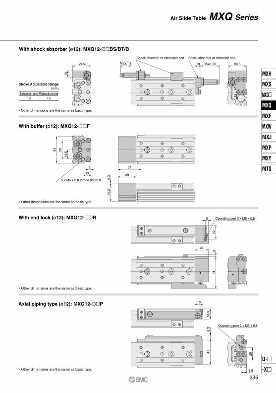
∗ Other dimensions are the same as basic type.
With buffer (ø12): MXQ12-F
∗ Other dimensions are the same as basic type.
With end lock (ø12): MXQ12-R
∗ Other dimensions are the same as basic type.
∗ Other dimensions are the same as basic type.
Axial piping type (ø12): MXQ12-P
Shock absorber at extension end Shock absorber at retraction end
29.510
Max. 18 10 Max. 30 29.5
3 x M5 x 0.8 thread depth 8
37
13
5
29
14.5
0.3
29.2
29
43
Operating port 2 x M5 x 0.8522
351
22
Operating port 2 x M5 x 0.8
416.
3
13
16.5
20
8.5
With shock absorber (ø12): MXQ12-BS/BT/B
Air Slide Table MXQ Series
235
MXH
MXS
MXQ
MXQ
MXF
MXW
MXJ
MXP
MXY
MTS
D-
-X
MXQ

Dimensions: MXQ12L/Symmetric Type
Model F28283834343636
N 4 4 4 6 6 810
G181820— 92312
H323240—393636
NN2223345
I12121415131717
J 3434425870
110135
K 26.5 36.5 46.5 56.5 66.5 91.5116.5
Z 66 66 76 93103147172
M 67 67 77 94104148173
ZZ 76 76 86103113157182
MXQ12L- 10MXQ12L- 20MXQ12L- 30MXQ12L- 40MXQ12L- 50MXQ12L- 75MXQ12L-100
(mm)
GA18182038485984
HA32324039397272
NA4444488
KA—————
117.5142.5
Basic type
∗ For detailed dimensions about the stroke adjuster, refer to the option for the stroke adjuster.Rubber stopper (Refer to page 250.)Metal stopper (Refer to page 253.)
Note 1) If long bolts are used, they can touch the guide block and cause malfunction, etc.
Refer to the Specific Product Precautions.Note 2) Since the table is made of a magnetic substance,
it could become magnetized if touched by a magnet, etc. This could cause auto switch malfunction.
Note)Note)
Note) Refer to the bottom view of MXQ12L-40.
B-BA-A
NN x M5 x 0.8 thread depth 10A
A
B
B
3 x M5 x 0.8 thread depth 8
Operating port 2 x M5 x 0.82 x M4 x 0.7 thread depth 6
N x M4 x 0.7thread depth 6 Note 1) Note 2)
Bottom view of MXQ12L-40
NA x M4 x 0.7 thread depth 4
4 x M4 x 0.7 thread depth 6
Adjuster at extension end Retraction end adjuster
27.2
0.3
30
8 M
Z
ZZ
16 8
ø4.
2 ø9
16 8
5
HA GA
13
5
29
4.75
8.5
58
J I
16
F
G(NN – 1) x H
H
ø4.
2 ø9
ø8.
5
939 29
5
19.5
14.5
2 9.5
1
2.5
20 39 46
5 8.5
18.5K
5 8.5
18.5KA
4.8
19
1
29.5 (Adjuster at extension end)
10 (
Adj
uste
r at
ext
ensi
on e
nd)
10
Max. 13 (Retraction end adjuster)
2N – 1 x F
ø4H9 ( ) depth 4+0.0300
4H9
(
)
dept
h 4
+0.
030
0
ø4H9 ( ) depth 4+0.0300
4H9
(
)
dept
h 4
+0.
030
0
MXQ Series
2220
4.58
236

Extension end18
Retraction end18
With shock absorber (ø12): MXQ12L-BS/BT/B
Stroke Adjustable Range(mm)
∗ Other dimensions are the same as basic type.
∗ Other dimensions are the same as basic type.
∗ Other dimensions are the same as basic type.
∗ Other dimensions are the same as basic type.
With buffer (ø12): MXQ12L-F
With end lock (ø12): MXQ12L-R
Axial piping type (ø12): MXQ12L-P
Shock absorber at extension end
Shock absorber at retraction end
29.5
10
Max. 18 10 Max. 30 29.5
3 x M5 x 0.8 thread depth 8
37
13
5
29
14.5
0.3
29.2
29
43
Operating port 2 x M5 x 0.85
223
51
22
Operating port 2 x M5 x 0.8
416.
3
13
16.5
20
8.5
Air Slide Table MXQ Series
237
MXH
MXS
MXQ
MXQ
MXF
MXW
MXJ
MXP
MXY
MTS
D-
-X
MXQ
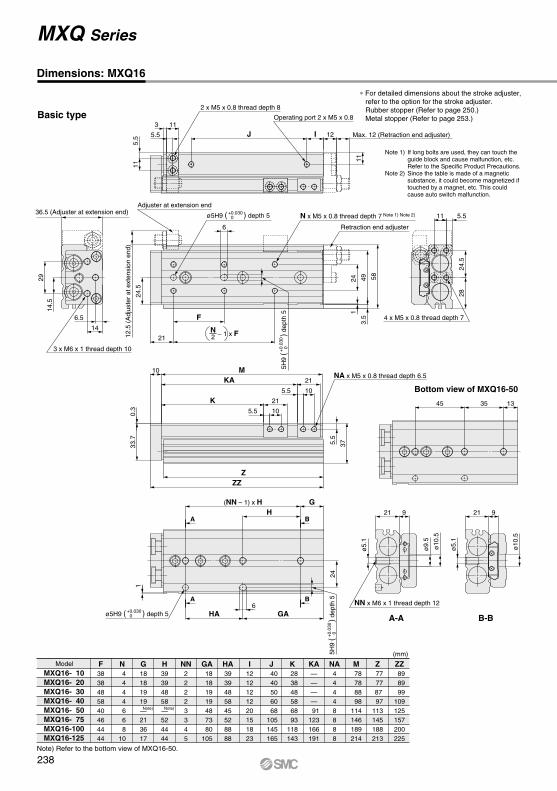
Dimensions: MXQ16
Model F3838485840464444
N 4 4 4 4 6 6 810
G18181919—213617
H39394858—524444
NN22223345
I1212121220151823
J 40
40 50 60 68105145165
K 28 38 48 58 68 93118143
Z 77 77 87 97113145188213
M 78 78 88 98114146189214
ZZ 89 89 99109125157200225
MXQ16- 10MXQ16- 20MXQ16- 30MXQ16- 40MXQ16- 50MXQ16- 75MXQ16-100MXQ16-125
(mm)
GA 18 18 19 19 48 73 80105
HA3939485845528888
NA44448888
KA————
91123166191
Basic type
∗ For detailed dimensions about the stroke adjuster, refer to the option for the stroke adjuster.Rubber stopper (Refer to page 250.)Metal stopper (Refer to page 253.)
Note 1) If long bolts are used, they can touch the guide block and cause malfunction, etc.
Refer to the Specific Product Precautions.Note 2) Since the table is made of a magnetic
substance, it could become magnetized if touched by a magnet, etc. This could cause auto switch malfunction.
Note)Note)
Note) Refer to the bottom view of MXQ16-50.
A-A
3 x M6 x 1 thread depth 10
4 x M5 x 0.8 thread depth 7
Operating port 2 x M5 x 0.8
2 x M5 x 0.8 thread depth 8
N x M5 x 0.8 thread depth 7 Note 1) Note 2) 5.5
2824
.5
11
Bottom view of MXQ16-50
NN x M6 x 1 thread depth 12
B-B
NA x M5 x 0.8 thread depth 6.5
Adjuster at extension end
Retraction end adjuster
14
6.5
14.5
29
5.511
J I
11
21
F
6
10 M
0.3
33.7
37
ZZZ
6HA
ø5.
1
ø9.
5
ø10
.5
21 9
G(NN – 1) x HH
5.5
GA
133545
24
24.5
ø5.
1
ø10
.521 9
3 11
124
3.5
49 58
5.5 10
21
5.5 10
21
K
KA
5.5
112 Max. 12 (Retraction end adjuster)
36.5 (Adjuster at extension end)
12.5
(A
djus
ter
at e
xten
sion
end
)
A
A
B
B
ø5H9 ( ) depth 5+0.0300
5H9
(
)
dept
h 5
+0.
030
0
2N – 1 x F
ø5H9 ( ) depth 5+0.0300
5H9
(
)
dept
h 5
+0.
030
0
MXQ Series
238
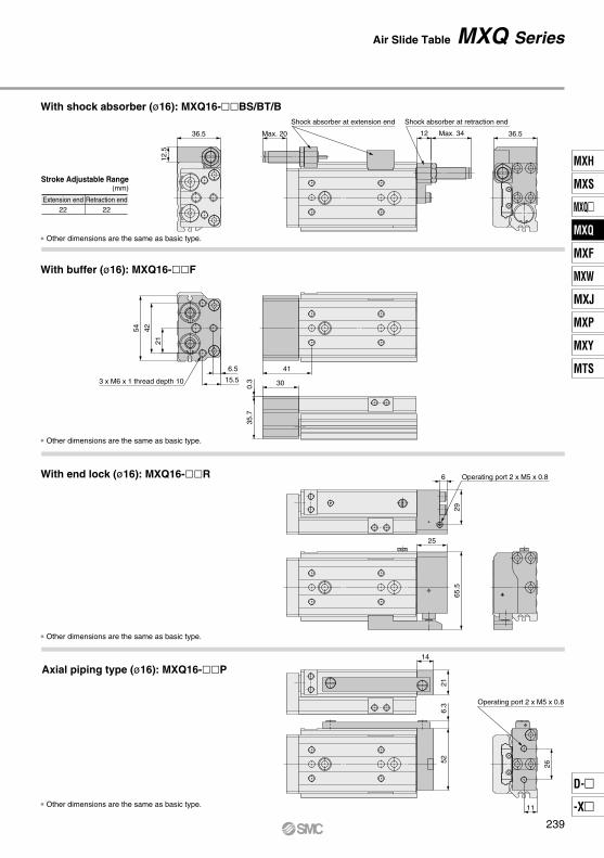
Extension end22
Retraction end22
Stroke Adjustable Range(mm)
∗ Other dimensions are the same as basic type.
∗ Other dimensions are the same as basic type.
∗ Other dimensions are the same as basic type.
∗ Other dimensions are the same as basic type.
With buffer (ø16): MXQ16-F
With end lock (ø16): MXQ16-R
Axial piping type (ø16): MXQ16-P
Shock absorber at extension end Shock absorber at retraction end
36.5
12.5
Max. 20 12 Max. 34 36.5
3 x M6 x 1 thread depth 10 300.3
35.7
6.5
15.5
21
4254
41
Operating port 2 x M5 x 0.86
2965
.5
25
Operating port 2 x M5 x 0.8
26
11
526.
321
14
With shock absorber (ø16): MXQ16-BS/BT/B
Air Slide Table MXQ Series
239
MXH
MXS
MXQ
MXQ
MXF
MXW
MXJ
MXP
MXY
MTS
D-
-X
MXQ

A-A
3 x M6 x 1 thread depth 10
Operating port 2 x M5 x 0.82 x M5 x 0.8 thread depth 8
N x M5 x 0.8 thread depth 7 Note 1) Note 2)
Bottom view of MXQ16L-50
NN x M6 x 1 thread depth 12
B-B
NA x M5 x 0.8 thread depth 6.5
Adjuster at extension end
Retraction end adjuster
146.5
14.5
29
5.5
11
J I
11
21
F
6
10 M
0.3
33.7 37
ZZZ
6
HA
ø5.
1
ø9.
5
ø10
.5
21 9
G(NN − 1) x HH
5.5
GA
133545
24
24.5
ø5.
1
ø10
.5
21 9
3 11
124
3.5
49 58
5.5 10
21
5.5 10
21
K
KA
5.5
1
12
Max. 12 (Retraction end adjuster)
36.5 (Adjuster at extension end)
12.5
(A
djus
ter
at e
xten
sion
end
)
ø5H9 ( ) depth 5+0.030 0
ø5H9 ( ) depth 5+0.030 0
A
A
B
B
Model F3838485840464444
N 4 4 4 4 6 6 810
G18181919—213617
H39394858—524444
NN22223345
I1212121220151823
J 40
40 50 60 68105145165
K 28 38 48 58 68 93118143
Z 77 77 87 97113145188213
M 78 78 88 98114146189214
ZZ 89 89 99109125157200225
MXQ16L- 10MXQ16L- 20MXQ16L- 30MXQ16L- 40MXQ16L- 50MXQ16L- 75MXQ16L-100MXQ16L-125
Basic type
(mm)
GA 18 18 19 19 48 73 80105
HA3939485845528888
NA44448888
∗ For detailed dimensions about the stroke adjuster,refer to the option for the stroke adjuster.Rubber stopper (Refer to page 250.)Metal stopper (Refer to page 253.)
KA————
91123166191
Note)
Note) Refer to the bottom view of MXQ16L-50.
Note)
Note 1) If long bolts are used, they can touch the guide block and cause malfunction, etc.Refer to the Specific Product Precautions.
Note 2) Since the table is made of a magnetic substance, it could become magnetized if touched by a magnet, etc. This could cause auto switch malfunction.
5.5
2824
.5
11
4 x M5 x 0.8 thread depth 7
MXQ Series
Dimensions: MXQ16L/Symmetric Type
5H9
(
)
dept
h 5
+0.0
30 0
5H9
(
)
dept
h 5
+0.0
30 0
2N – 1 x F
240

Shock absorber at extension end Shock absorber at retraction end
36.5
12.5
Max. 20 12 Max. 34 36.5
3 x M6 x 1 thread depth 10 30
0.3
35.7
6.5
15.5
21
4254
41
Operating port 2 x M5 x 0.86
2965
.5
25
Operating port 2 x M5 x 0.8
26
11
526.
321
14
∗ Other dimensions are the same as basic type.
∗ Other dimensions are the same as basic type.
With shock absorber (ø16): MXQ16L-BS/BT/B
With buffer (ø16): MXQ16L-F
∗ Other dimensions are the same as basic type.
With end lock (ø16): MXQ16L-R
∗ Other dimensions are the same as basic type.
Axial piping type (ø16): MXQ16L-P
Extension end22
Retraction end22
Stroke Adjustable Range(mm)
Air Slide Table MXQ Series
241
MXH
MXS
MXQ
MXQ
MXF
MXW
MXJ
MXP
MXY
MTS
D-
-X
MXQ
Bottom view of MXQ20-50
B-B
N x M5 x 0.8 thread depth 9.5 Note 1) Note 2)
3 x M6 x 1 thread depth 13
A-A
NN x M6 x 1 thread depth 12
NA x M6 x 1 thread depth 6
Adjuster at extension end
Retraction end adjuster
26 10.5
ø5.
1
ø11
6
2746
0.5
41.5
13
6
F
M
ZZZ
GAHA
HG
30
1248 36
(NN − 1) x H
18
7
35
17.5
26 10.5
ø5.
1
ø9.
5
ø11
1.5
30
360 70
6.5 12
25K6.5 12
25KA
6.5
1.5
29
45.5 (Adjuster at extension end)
14.5
(A
djus
ter
at e
xten
sion
end
)
BA
A B
Operating port 2 x Rc 1/8 (NPT 1/8, G 1/8)
2 x M6 x 1 thread depth 7
14
J I6.
513
.52.5 13
13 Max. 14 (Retraction end adjuster)6.5
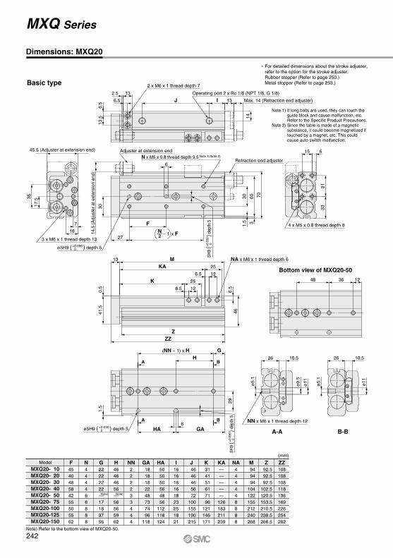
Model F454048584255505562
N444466888
G22222222—17183756
H46464656—56565962
NN222233444
I161616161823251821
J 46
46 46 56 72100155190215
K 31 41 51 61 71 96121146171
Z 92.5 92.5 92.5102.5120.5153.5210.5238.5266.5
M 94 94 94104122155212240268
ZZ108108108118136169226254282
MXQ20- 10MXQ20- 20MXQ20- 30MXQ20- 40MXQ20- 50MXQ20- 75MXQ20-100MXQ20-125MXQ20-150
Basic type
(mm)
GA 18 18 18 22 48 73 74 96118
HA 50
50 50 56 48 56112118124
NA444448888
KA—————
126183211239
Note)
Note) Refer to the bottom view of MXQ20-50.
Note)
3331
615
4 x M5 x 0.8 thread depth 8
MXQ Series
Dimensions: MXQ20
∗ For detailed dimensions about the stroke adjuster,refer to the option for the stroke adjuster.Rubber stopper (Refer to page 250.)Metal stopper (Refer to page 253.)
Note 1) If long bolts are used, they can touch the guide block and cause malfunction, etc.Refer to the Specific Product Precautions.
Note 2) Since the table is made of a magnetic substance, it could become magnetized if touched by a magnet, etc. This could cause auto switch malfunction.
ø5H9 ( ) depth 5+0.030 0
ø5H9 ( ) depth 5+0.030 0
5H9
(
)
dept
h 5
+0.0
30 0
5H9
(
)
dept
h 5
+0.0
30 0
2N – 1 x F
242
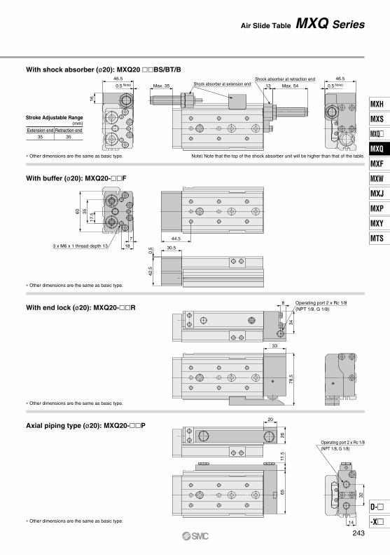
Shock absorber at extension endShock absorber at retraction end
0.5 Note)
46.5
16Max. 35 13 Max. 54 0.5 Note)
46.5
3 x M6 x 1 thread depth 13
44.57
18
17.53560
30.5
0.5
42.5
Operating port 2 x Rc 1/8(NPT 1/8, G 1/8)
78.5
33
34
8
Operating port 2 x Rc 1/8(NPT 1/8, G 1/8)
14
32
26
20
11.5
65
∗ Other dimensions are the same as basic type.
∗ Other dimensions are the same as basic type.
With shock absorber (ø20): MXQ20 BS/BT/B
With buffer (ø20): MXQ20-F
∗ Other dimensions are the same as basic type.
With end lock (ø20): MXQ20-R
∗ Other dimensions are the same as basic type.
Axial piping type (ø20): MXQ20-P
Extension end35
Retraction end35
Stroke Adjustable Range(mm)
Note) Note that the top of the shock absorber unit will be higher than that of the table.
Air Slide Table MXQ Series
243
MXH
MXS
MXQ
MXQ
MXF
MXW
MXJ
MXP
MXY
MTS
D-
-X
MXQ

Dimensions: MXQ20L/Symmetric Type
Model F454048584255505562
N444466888
G22222222—17183756
H46464656—56565962
NN222233444
I161616161823251821
J 46
46 46 56 72100155190215
K 31 41 51 61 71 96121146171
Z 92.5 92.5 92.5102.5120.5153.5210.5238.5266.5
M 94 94 94104122155212240268
ZZ108108108118136169226254282
MXQ20L- 10MXQ20L- 20MXQ20L- 30MXQ20L- 40MXQ20L- 50MXQ20L- 75MXQ20L-100MXQ20L-125MXQ20L-150
Basic type
(mm)
GA 18 18 18 22 48 73 74 96118
HA 50
50 50 56 48 56112118124
NA444448888
KA—————
126183211239
∗ For detailed dimensions about the stroke adjuster, refer to the option for the stroke adjuster.Rubber stopper (Refer to page 250.)Metal stopper (Refer to page 253.)
Note 1) If long bolts are used, they can touch the guide block and cause malfunction, etc.
Refer to the Specific Product Precautions.Note 2) Since the table is made of a magnetic substance,
it could become magnetized if touched by a magnet, etc. This could cause auto switch malfunction.
Note)Note)
Note) Refer to the bottom view of MXQ20L-50.
Bottom view of MXQ20L-50
B-B
Operating port 2 x Rc 1/8 (NPT 1/8, G 1/8)
N x M5 x 0.8 thread depth 9.5 Note 1) Note 2)
2 x M6 x 1 thread depth 7
4 x M5 x 0.8 thread depth 8
3 x M6 x 1 thread depth 13
A-A
NN x M6 x 1 thread depth 12
NA x M6 x 1 thread depth 6
Adjuster at extension end
Retraction end adjuster
26 10.5
ø5.
1
ø11
146
27
46
0.5
41.5
13
6
J I
F
M
ZZZ
GAHA
HG
30
1248 36
(NN – 1) x H
6.5
13.5
18
7
35
17.5
26 10.5
ø5.
1
ø9.
5
ø11
2.5 13
1.5
30
360 70
6.5 12
25K6.5 12
25KA
6.5
1.5
29
13
Max. 14 (Retraction end adjuster)
45.5 (Adjuster at extension end)
14.5
(A
djus
ter
at e
xten
sion
end
)
6.5
A B
A B
ø5H9 ( ) depth 5+0.0300
2N – 1 x F
MXQ Series
3331
615
ø5H9 ( ) depth 5+0.0300 5H
9 (
) de
pth
5+0
.030
05H
9 (
) de
pth
5+0
.030
0
244
Extension end35
Retraction end35
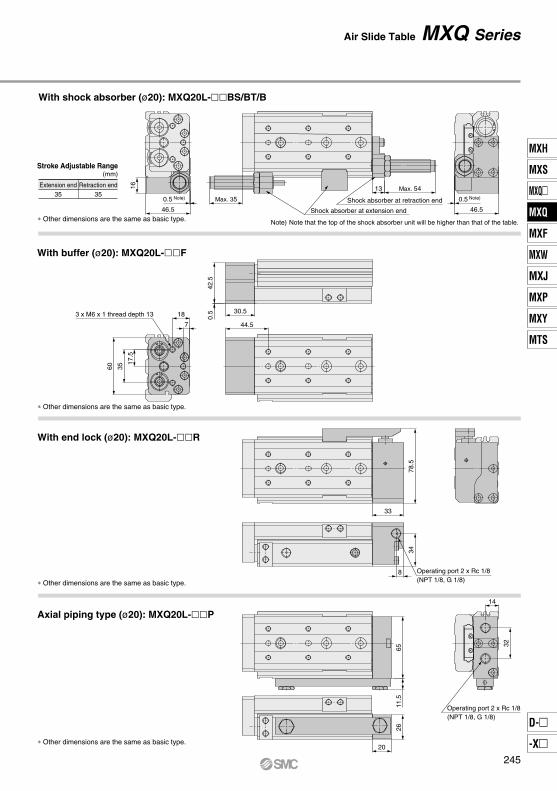
With shock absorber (ø20): MXQ20L-BS/BT/B
Stroke Adjustable Range(mm)
∗ Other dimensions are the same as basic type.
∗ Other dimensions are the same as basic type.
∗ Other dimensions are the same as basic type.
∗ Other dimensions are the same as basic type.
Note) Note that the top of the shock absorber unit will be higher than that of the table.
3 x M6 x 1 thread depth 13
44.57
18
17.5
3560
30.5
0.5
42.5
With buffer (ø20): MXQ20L-F
With end lock (ø20): MXQ20L-R
Axial piping type (ø20): MXQ20L-P
Shock absorber at extension end
Shock absorber at retraction end0.5 Note)
46.5
16
Max. 35
13 Max. 54
0.5 Note)
46.5
Operating port 2 x Rc 1/8 (NPT 1/8, G 1/8)
78.5
33
34
8
Operating port 2 x Rc 1/8 (NPT 1/8, G 1/8)
14
32
26
20
11.5
65
Air Slide Table MXQ Series
245
MXH
MXS
MXQ
MXQ
MXF
MXW
MXJ
MXP
MXY
MTS
D-
-X
MXQ
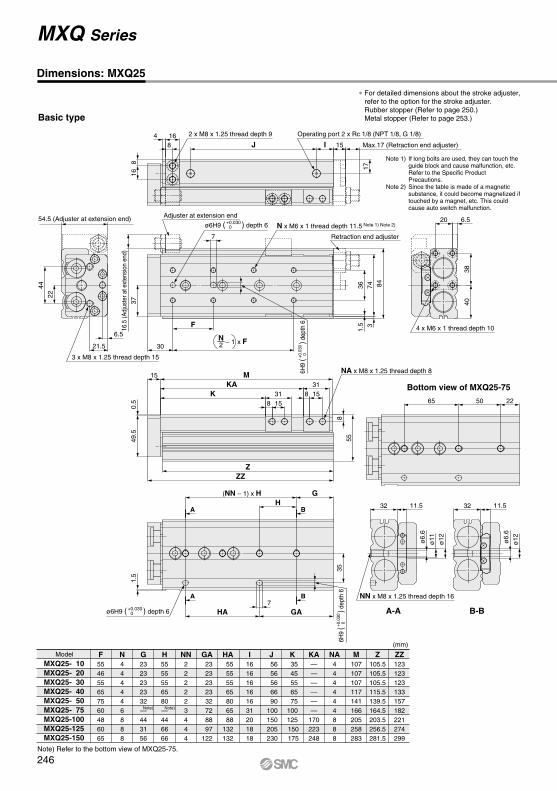
Dimensions: MXQ25
Model F554655657560486065
N444446888
G2323232332—443156
H5555556580—446666
NN222223444
I161616161631201818
J 56
56 56 66 90100150205230
K 35 45 55 65 75100125 150 175
Z105.5105.5105.5115.5139.5164.5203.5256.5281.5
M107107107117141166205258283
ZZ123123123133157182221274299
MXQ25- 10MXQ25- 20MXQ25- 30MXQ25- 40MXQ25- 50MXQ25- 75MXQ25-100MXQ25-125MXQ25-150
Basic type
(mm)
GA 23 23 23 23 32 72 88 97122
HA 55 55 55 65 80 65 88132132
NA444444888
KA——————
170223248
∗ For detailed dimensions about the stroke adjuster, refer to the option for the stroke adjuster.Rubber stopper (Refer to page 250.)Metal stopper (Refer to page 253.)
Note 1) If long bolts are used, they can touch the guide block and cause malfunction, etc.
Refer to the Specific Product Precautions.
Note 2) Since the table is made of a magnetic substance, it could become magnetized if touched by a magnet, etc. This could cause auto switch malfunction.
Note) Refer to the bottom view of MXQ25-75.
B-BA-A
Bottom view of MXQ25-75
4 x M6 x 1 thread depth 10
2 x M8 x 1.25 thread depth 9
N x M6 x 1 thread depth 11.5 Note 1) Note 2)
3 x M8 x 1.25 thread depth 15
Operating port 2 x Rc 1/8 (NPT 1/8, G 1/8)
NA x M8 x 1.25 thread depth 8
NN x M8 x 1.25 thread depth 16
Adjuster at extension end
Retraction end adjuster
21.5
6.5
4422
30
7
ø12
32 11.5
ZZZ
15 M
0.5
49.5
55
7HA GA
G (NN – 1) x HH
816
J I
F
225065
8
17
37
ø6.
6
ø11
ø12
32 11.5
ø6.
6
4 16
1.5 3
36 74 84
8 1531K 8 15
31KA
835
1.5
15 Max.17 (Retraction end adjuster)
54.5 (Adjuster at extension end)
16.5
(Adj
uste
r at e
xten
sion
end
)
A
A B
B
2N – 1 x F
Note)Note)
MXQ Series
4038
6.520ø6H9 ( ) depth 6+0.030
0
ø6H9 ( ) depth 6+0.0300
6H9
(
)
dept
h 6
+0.0
300
6H9
(
)
dept
h 6
+0.0
300
246
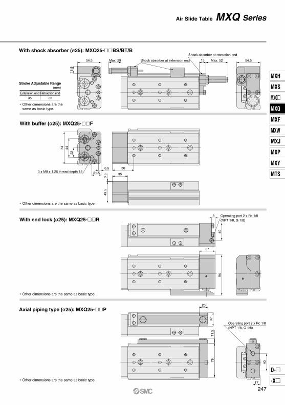
Extension end35
Retraction end35
With shock absorber (ø25): MXQ25-BS/BT/B
Stroke Adjustable Range(mm)
∗ Other dimensions are the same as basic type.
∗ Other dimensions are the same as basic type.
∗ Other dimensions are the same as basic type.
∗ Other dimensions are the same as basic type.
With buffer (ø25): MXQ25-F
With end lock (ø25): MXQ25-R
Axial piping type (ø25): MXQ25-P
Shock absorber at extension end
Shock absorber at retraction end
54.5
16.5
Max. 29 15 Max. 52 54.5
3 x M8 x 1.25 thread depth 1550
35
0.5
49.5
6.521.5
224474
Operating port 2 x Rc 1/8 (NPT 1/8, G 1/8)
408
37
94
Operating port 2 x Rc 1/8 (NPT 1/8, G 1/8)
17
407911
.532
20
Air Slide Table MXQ Series
247
MXH
MXS
MXQ
MXQ
MXF
MXW
MXJ
MXP
MXY
MTS
D-
-X
MXQ

Dimensions: MXQ25L/Symmetric Type
Model F554655657560486065
N444446888
G2323232332—443156
H5555556580—446666
NN222223444
I161616161631201818
J 56
56 56 66 90100150205230
K 35 45 55 65 75100125 150 175
Z105.5105.5105.5115.5139.5164.5203.5256.5281.5
M107107107117141166205258283
ZZ123123123133157182221274299
MXQ25L- 10MXQ25L- 20MXQ25L- 30MXQ25L- 40MXQ25L- 50MXQ25L- 75MXQ25L-100MXQ25L-125MXQ25L-150
(mm)
GA 23 23 23 23 32 72 88 97122
HA 55 55 55 65 80 65 88132132
NA444444888
KA——————
170223248
Basic type
∗ For detailed dimensions about the stroke adjuster, refer to the option for the stroke adjuster.Rubber stopper (Refer to page 250.)Metal stopper (Refer to page 253.)
Note 1) If long bolts are used, they can touch the guide block and cause malfunction, etc.
Refer to the Specific Product Precautions.Note 2) Since the table is made of a magnetic substance,
it could become magnetized if touched by a magnet, etc. This could cause auto switch malfunction.
Note) Refer to the bottom view of MXQ25L-75.
Note)Note)
B-BA-A
Bottom view of MXQ25L-75
4 x M6 x 1 thread depth 10
2 x M8 x 1.25 thread depth 9
N x M6 x 1 thread depth 11.5 Note 1) Note 2)
3 x M8 x 1.25 thread depth 15
Operating port 2 x Rc 1/8 (NPT 1/8, G 1/8)
NA x M8 x 1.25 thread depth 8
NN x M8 x 1.25 thread depth 16
Adjuster at extension end
Retraction end adjuster
21.56.5
4422
30
7
ø12
32 11.5
ZZZ
15 M
0.5
49.5 55
7HA GA
G (NN – 1) x HH
816
J I
F
225065
8
17
37
ø6.
6
ø11
ø12
32 11.5
ø6.
6
4 16
1.5
336 74 84
8 1531K 8 15
31KA
835
1.5
15
Max. 17 (Retraction end adjuster)
54.5 (Adjuster at extension end)
16.5
(Adj
uste
r at e
xten
sion
end
)
A
A
B
B
2N – 1 x F
MXQ Series
4038
6.520ø6H9 ( ) depth 6+0.0300
ø6H9 ( ) depth 6+0.0300
6H9
(
)
dept
h 6
+0.
030
0
6H9
(
)
dept
h 6
+0.0
300
248

Extension end35
Retraction end35
Stroke Adjustable Range(mm)
∗ Other dimensions are the same as basic type.
∗ Other dimensions are the same as basic type.
∗ Other dimensions are the same as basic type.
∗ Other dimensions are the same as basic type.
With buffer (ø25): MXQ25L-F
With end lock (ø25): MXQ25L-R
Axial piping type (ø25): MXQ25L-P
Shock absorber at extension end Shock absorber at retraction end
54.5
16.5
Max. 29 15 Max. 52 54.5
3 x M8 x 1.25 thread depth 15
50
35
0.5
49.5
6.521.5
224474
Operating port 2 x Rc 1/8 (NPT 1/8, G 1/8)
40
8
37
94
With shock absorber (ø25): MXQ25L-BS/BT/B
Operating port 2 x Rc 1/8 (NPT 1/8, G 1/8)
17
407911
.532
20
Air Slide Table MXQ Series
249
MXH
MXS
MXQ
MXQ
MXF
MXW
MXJ
MXP
MXY
MTS
D-
-X
MXQ

External Dimensions of Adjuster
Extension End
Applicable size
MXQ 6 (L)
MXQ 8 (L)
MXQ12 (L)
MXQ16 (L)
MXQ20 (L)
MXQ25 (L)
Model
MXQ-AS 6 (L)
MXQ-AS 6 (L)-X11
MXQ-AS 8 (L)
MXQ-AS 8( L)-X11
MXQ-AS 8 (L)-X12
MXQ-AS12 (L)
MXQ-AS12 (L)-X11
MXQ-AS12 (L)-X12
MXQ-AS16 (L)
MXQ-AS16 (L)-X11
MXQ-AS16 (L)-X12
MXQ-AS20 (L)
MXQ-AS20 (L)-X11
MXQ-AS20 (L)-X12
MXQ-AS25 (L)
MXQ-AS25 (L)-X11
MXQ-AS25 (L)-X12
5
15
5
15
25
5
15
25
5
15
25
5
15
25
5
15
25
Strokeadjustment range
(mm)
Body mounting section Table mounting section
A
6
7
9.5
11
13
16
Retraction End
Applicable size
MXQ 6 (L)
MXQ 8 (L)
MXQ12 (L)
MXQ16 (L)
MXQ20 (L)
MXQ25 (L)
Model
MXQ-AT 6 (L)
MXQ-AT 6 (L)-X11
MXQ-AT 8 (L)
MXQ-AT 8 (L)-X11
MXQ-AT 8 (L)-X12
MXQ-AT12 (L)
MXQ-AT12 (L)-X11
MXQ-AT12 (L)-X12
MXQ-AT16 (L)
MXQ-AT16 (L)-X11
MXQ-AT16 (L)-X12
MXQ-AT20 (L)
MXQ-AT20 (L)-X11
MXQ-AT20 (L)-X12
5
15
5
15
25
5
15
25
5
15
25
5
15
25
5
15
25
Strokeadjustment range
(mm)
B C F G M
M5 x 0.8
M6 x 1
M8 x 1
M10 x 1
M12 x 1.25
M14 x 1.5
P ∗1)
M2.5 x 6
M3 x 8
M4 x 12
M5 x 16
M6 x 16
M8 x 18
H J K Q ∗1)
M2.5 x 8
M3 x 10
M4 x 12
M5 x 16
M6 x 16
M8 x 18
16.5
26.5
19.5
29.5
39.5
23.5
33.5
43.5
24.5
34.5
44.5
27.5
37.5
47.5
32.5
42.5
52.5
D
A
17.5
21
28
33.5
41
49
B C F G H J K ∗1) ED
M5 x 0.8
M6 x 1
M8 x 1
M10 x 1
M12 x 1.25
M14 x 1.5
M2.5 x 6
M3 x 8
M4 x 10
M5 x 12
M5 x 14
M6 x 18
E
19
22
29
36
45
54
8
9
14
17
20
22
7
7.5
11
13.5
16
18
7
8
12
14
17
19
2.5
3
4
5
6
6
12.5
14.6
18.5
21
25
31
6
7
10.5
13
16
17
8.3
9.8
12.7
15
18
20
MXQ-AT25 (L)
MXQ-AT25 (L)-X11
MXQ-AT25 (L)-X12
19
22
29
35.5
44.5
53.5
10.5
12.5
16
20
25
31
8
10
16
17
23
28
16.5
26.5
19.5
29.5
39.5
23.5
33.5
43.5
24.5
34.5
44.5
27.5
37.5
47.5
32.5
42.5
52.5
6
8
10
12
13
15
7
8
12
14
17
19
2.5
3
4
5
6
6
H
J
Q
K
AB
E
P
M
G
D
F
C
E
J
F
BC
DH
G
AK
Rubber Stopper (AS/AT)
Body mounting section
Table mounting section
∗1) Size of hexagon socket head cap screw∗2) It is also available in the symmetric type. For “How to Order”, refer to page 222. Dimensions are the same as standard type.
∗1) Size of hexagon socket head cap screw∗2) It is also available in the symmetric type. For “How to Order”, refer to page 222. Dimensions are the same as standard type.
MXQ Series
250

Dimensions of Adjusting Bolt/Rubber Stopper
MXQ
5 mm15 mm25 mm
6812162025
ø6ø8ø12ø16ø20ø25
12 X11
How to Order Adjusting Bolt/Rubber Stopper
Applicablesize
MXQ 6 (L)
MXQ 8 (L)
MXQ12 (L)
MXQ16 (L)
MXQ20 (L)
MXQ25 (L)
Model
MXQ-A627
MXQ-A627-X11
MXQ-A827
MXQ-A827-X11
MXQ-A827-X12
MXQ-A1227
MXQ-A1227-X11
MXQ-A1227-X12
MXQ-A1627
MXQ-A1627-X11
MXQ-A1627-X12
MXQ-A2027
MXQ-A2027-X11
MXQ-A2027-X12
MXQ-A2527
MXQ-A2527-X11
MXQ-A2527-X12
5
15
5
15
25
5
15
25
5
15
25
5
15
25
5
15
25
Strokeadjustment range
(mm)A B
2.5
3
4
5
6
6
C
716.5
26.5
19.5
29.5
39.5
23.5
33.5
43.5
24.5
34.5
44.5
27.5
37.5
47.5
32.5
42.5
52.5
8
12
14
17
19
MD
3.5
4
4
4
5
6
M5 x 0.8
M6 x 1
M8 x 1
M10 x 1
M12 x 1.25
M14 x 1.5
A 27
B D C
A
M
Applicable bore sizeAdjustment rangeNil
-X11-X12
∗ -X12 (adjusting range: 25 mm) is not available in the MXQ6 series.∗ For dimensions, refer to the figure above. ∗ Symmetric type is also the same.
Air Slide Table MXQ Series
251
MXH
MXS
MXQ
MXQ
MXF
MXW
MXJ
MXP
MXY
MTS
D-
-X
MXQ

Extension End
Applicable size
MXQ 8 (L)MXQ12 (L)MXQ16 (L)MXQ20 (L)MXQ25 (L)
Model
MXQ-BS 8 (L)
MXQ-BS12 (L)
MXQ-BS16 (L)
MXQ-BS20 (L)
MXQ-BS25 (L)
Body mounting section Table mounting section
A
Retraction End
MXQ 8 (L)MXQ12 (L)MXQ16 (L)MXQ20 (L)MXQ25 (L)
Model
MXQ-BT 8 (L)
MXQ-BT12 (L)
MXQ-BT16 (L)
MXQ-BT20 (L)
MXQ-BT25 (L)
20
18
22
35
35
B C F G MM8 x 1
M8 x 1
M10 x 1
M14 x 1.5
M14 x 1.5
P *1)
M3 x 12
M4 x 12
M5 x 16
M6 x 18
M8 x 18
H J K Q ∗1)
M3 x 12
M4 x 12
M5 x 16
M6 x 20
M8 x 20
D
A B C E1 G H J K ∗1) ED
M8 x 1
M8 x 1
M10 x 1
M14 x 1.5
M14 x 1.5
Body mounting section Table mounting section
E
23
28
33.5
43
49
24.5
29
35.5
46
53.5
12.5
16
20
26
31
14
16
17
25
28
40.8
40.8
46.7
67.3
67.3
5
6
7
11
12
F
8
10
12
13
15
12
12
14
19
19
1.4
1.4
1.4
12
12
M3 x 8
M4 x 10
M5 x 12
M5 x 14
M6 x 18
20
18
22
35
35
7
9.5
11
13
16
24.5
29
36
46
54
14
14
17
22
22
12.5
11
13.5
17.5
18
LE140.8
40.8
46.7
67.3
67.3
5
6
7
11
12
12
12
14
19
19
1.4
1.4
1.4
12
12
16.6
20.5
23
27
33
8
11
13.5
17
19
12
13
16
22
22
14.6
18.5
21
25
31
MXQ-BT20 (L)MXQ-BT25 (L)
H
MXQ-BT 8 (L)MXQ-BT12 (L)MXQ-BT16 (L)
MXQ-BS 8 (L)MXQ-BS12 (L)MXQ-BS16 (L)
MXQ-BS20 (L)MXQ-BS25 (L)
G
D
F
C
G
P
M
E E1
B
A
Q
J
H
L
K
J
EF
E1D
AK
H
BC
G
External Dimensions of Adjuster
With Shock Absorber (BS/BT)
Strokeadjustment range
(mm)
∗1) Size of hexagon socket head cap screw∗2) It is also available in the symmetric type. For “How to Order”, refer to page 222. Dimensions are the same as standard type.
Applicable size
Strokeadjustment range
(mm)
∗1) Size of hexagon socket head cap screw∗2) It is also available in the symmetric type. For “How to Order”, refer to page 222. Dimensions are the same as standard type.
MXQ Series
252
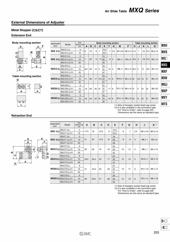
External Dimensions of Adjuster
Extension End
MXQ 6 (L)
MXQ 8 (L)
MXQ12 (L)
MXQ16 (L)
MXQ20 (L)
MXQ25 (L)
MXQ-CS 6 (L)
MXQ-CS 6 (L)-X11
MXQ-CS 8 (L)
MXQ-CS 8 (L)-X11
MXQ-CS 8 (L)-X12
MXQ-CS12 (L)
MXQ-CS12 (L)-X11
MXQ-CS12 (L)-X12
MXQ-CS16 (L)
MXQ-CS16 (L)-X11
MXQ-CS16 (L)-X12
MXQ-CS20 (L)
MXQ-CS20 (L)-X11
MXQ-CS20 (L)-X12
MXQ-CS25 (L)
MXQ-CS25 (L)-X11
MXQ-CS25 (L)-X12
5
15
5
15
25
5
15
25
5
15
25
5
15
25
5
15
25
Body mounting section Table mounting section
A
6
7
9.5
11
13
16
Retraction End
MXQ 6 (L)
MXQ 8 (L)
MXQ12 (L)
MXQ16 (L)
MXQ20 (L)
MXQ25 (L)
MXQ-CT 6 (L)
MXQ-CT 6 (L)-X11
MXQ-CT 8 (L)
MXQ-CT 8 (L)-X11
MXQ-CT 8 (L)-X12
MXQ-CT12 (L)
MXQ-CT12 (L)-X11
MXQ-CT12 (L)-X12
MXQ-CT16 (L)
MXQ-CT16 (L)-X11
MXQ-CT16 (L)-X12
MXQ-CT20 (L)
MXQ-CT20 (L)-X11
MXQ-CT20 (L)-X12
5
15
5
15
25
5
15
25
5
15
25
5
15
25
5
15
25
B C F G M
M5 x 0.8
M6 x 1
M8 x 1
M10 x 1
M12 x 1.25
M14 x 1.5
M2.5 x 6
M3 x 8
M4 x 12
M5 x 16
M6 x 16
M8 x 18
H J K
M2.5 x 8
M3 x 10
M4 x 12
M5 x 16
M6 x 20
M8 x 20
15.5
25.5
18
28
38
22
32
42
23
33
43
27
37
47
30
40
50
D
A
17.5
21
28
33.5
41
49
B C F G H JED
M5 x 0.8
M6 x 1
M8 x 1
M10 x 1
M12 x 1.25
M14 x 1.5
M2.5 x 6
M3 x 8
M4 x 10
M5 x 12
M5 x 14
M6 x 18
E
19
22
29
36
45
54
8
9
14
17
20
22
7
7.5
11
13.5
16
18
7
8
12
14
17
19
2.5
3
4
5
6
6
14.5
16.6
20.5
23
27
33
7
8
11
13.5
17
19
8.3
9.8
13
16
22
22
MXQ-CT25 (L)
MXQ-CT25 (L)-X11
MXQ-CT25 (L)-X12
19
22
29
35.5
44.5
53.5
10.5
12.5
16
20
25
31
8
10
16
17
23
28
15.5
25.5
18
28
38
22
32
42
23
33
43
27
37
47
30
40
50
6
8
10
12
13
15
7
8
12
14
17
19
2.5
3
4
5
6
6
L
12.5
14.6
18.5
21
25
31
AB
E
P
M
G
D
F
C
E
J
F
BC
DH
G
AK
Q
J
H
L
K
Metal Stopper (CS/CT)
Body mounting section
Table mounting section
Applicablesize
ModelStroke
adjustment range(mm) P ∗1) Q ∗1)
∗1) Size of hexagon socket head cap screw∗2) It is also available in the symmetric type. For “How to Order”, refer to page 222. Dimensions are the same as standard type.
Applicablesize
ModelStroke
adjustment range(mm)
K ∗1)
∗1) Size of hexagon socket head cap screw∗2) It is also available in the symmetric type. For “How to Order”, refer to page 222. Dimensions are the same as standard type.
Air Slide Table MXQ Series
253
MXH
MXS
MXQ
MXQ
MXF
MXW
MXJ
MXP
MXY
MTS
D-
-X
MXQ
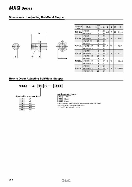
Dimensions of Adjusting Bolt/Metal Stopper
MXQ
5 mm15 mm25 mm
6812162025
ø6ø8ø12ø16ø20ø25
12 X11
MXQ 6 (L)
MXQ 8 (L)
MXQ12 (L)
MXQ16 (L)
MXQ20 (L)
MXQ25 (L)
MXQ-A638
MXQ-A638-X11
MXQ-A838
MXQ-A838-X11
MXQ-A838-X12
MXQ-A1238
MXQ-A1238-X11
MXQ-A1238-X12
MXQ-A1638
MXQ-A1638-X11
MXQ-A1638-X12
MXQ-A2038
MXQ-A2038-X11
MXQ-A2038-X12
MXQ-A2538
MXQ-A2538-X11
MXQ-A2538-X12
5
15
5
15
25
5
15
25
5
15
25
5
15
25
5
15
25
A B
2.5
3
4
5
6
6
C
715.5
25.5
18
28
38
22
32
42
23
33
43
27
37
47
30
40
50
8
12
14
17
19
MD
3.5
4
4
4
5
6
M5 x 0.8
M6 x 1
M8 x 1
M10 x 1
M12 x 1.25
M14 x 1.5
A 38
C
A
DMB
How to Order Adjusting Bolt/Metal Stopper
Applicablesize
ModelStroke
adjustment range(mm)
Applicable bore sizeAdjustment rangeNil
-X11-X12
∗ -X12 (adjusting range: 25 mm) is not available in the MXQ6 series.∗ For dimensions, refer to the figure above. ∗ Symmetric type is also the same.
MXQ Series
254
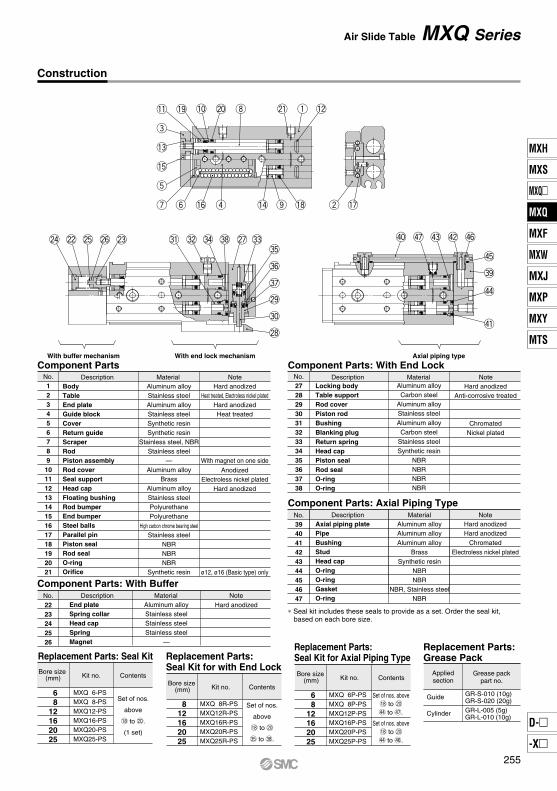
wu y
t
!6 r !4 !8o
!5
!3
e
!1 !9 !0 @0 i @1 q !2
!7
@4 @2 @5 @6 @3 #1 #2 #4 #8 @7 #3#5
#6
#7
@9
#0
@8
$0 $7 $3 $2 $6
$5
#9
$4
$1
Construction
DescriptionBodyTable End plateGuide blockCoverReturn guideScraperRodPiston assembly Rod coverSeal supportHead capFloating bushingRod bumperEnd bumperSteel ballsParallel pinPiston sealRod sealO-ringOrifice
No.123456789101112131415161718192021
Aluminum alloyStainless steelAluminum alloyStainless steelSynthetic resinSynthetic resin
Stainless steel, NBRStainless steel
—Aluminum alloy
BrassAluminum alloyStainless steelPolyurethanePolyurethane
High carbon chrome bearing steel
Stainless steelNBRNBRNBR
Synthetic resin
MaterialHard anodized
Heat treated, Electroless nickel platedHard anodizedHeat treated
With magnet on one side
AnodizedElectroless nickel plated
Hard anodized
ø12, ø16 (Basic type) only
Note
Component Parts
No.2223242526
DescriptionEnd plateSpring collarHead capSpringMagnet
Aluminum alloyStainless steelStainless steelStainless steel
—
Material NoteHard anodized
Component Parts: With Buffer
Replacement Parts: Seal Kit
68
12162025
Bore size (mm)
No.272829303132333435363738
DescriptionLocking bodyTable support Rod coverPiston rodBushingBlanking plug Return springHead capPiston sealRod sealO-ringO-ring
Aluminum alloyCarbon steel
Aluminum alloyStainless steelAluminum alloyCarbon steel
Stainless steelSynthetic resin
NBRNBRNBRNBR
MaterialHard anodized
Anti-corrosive treated
ChromatedNickel plated
Note
Component Parts: With End Lock
No.394041424344454647
DescriptionAxial piping plate PipeBushingStudHead capO-ringO-ringGasketO-ring
Aluminum alloyAluminum alloyAluminum alloy
BrassSynthetic resin
NBRNBR
NBR, Stainless steelNBR
MaterialHard anodizedHard anodized
ChromatedElectroless nickel plated
Note
Component Parts: Axial Piping Type
Kit no.
MXQ 6-PSMXQ 8-PSMXQ12-PSMXQ16-PSMXQ20-PSMXQ25-PS
Contents
68
12162025
MXQ 6P-PSMXQ 8P-PSMXQ12P-PSMXQ16P-PSMXQ20P-PSMXQ25P-PS
812162025
MXQ 8R-PSMXQ12R-PSMXQ16R-PSMXQ20R-PSMXQ25R-PS
Grease packpart no.
GR-S-010 (10g)GR-S-020 (20g)GR-L-005 (5g)GR-L-010 (10g)
Appliedsection
Guide
Cylinder
Replacement Parts: Seal Kit for with End Lock
Bore size (mm) Kit no. Contents
Bore size (mm) Kit no. Contents
Replacement Parts:Seal Kit for Axial Piping Type
Replacement Parts:Grease Pack
∗ Seal kit includes these seals to provide as a set. Order the seal kit, based on each bore size.
Air Slide Table MXQ Series
With buffer mechanism With end lock mechanism Axial piping type
Set of nos.
above
!8 to @0.
(1 set)
Set of nos. above!8 to @0
$4 to $7.
Set of nos. above!8 to @0
$4 to $6.
Set of nos.
above
!8 to @0
#5 to #8.
255
MXH
MXS
MXQ
MXQ
MXF
MXW
MXJ
MXP
MXY
MTS
D-
-X
MXQ

Auto Switch Proper Mounting Position (Detection at Stroke End)
MXQ6MXQ8MXQ12MXQ16MXQ20MXQ25
6
7.5
11.5
16.5
19
22
Reed Auto Switch: D-A90, D-A93, D-A96, D-A90V, D-A93V, D-A96V
10
5.5
8
24.5
30.5
43.5
52.5
20
5.5
8
14.5
20.5
33.5
42.5
30
5.5
12
14.5
20.5
23.5
32.5
125
—
—
—
51.5
74.5
88.5
75
—
32
40.5
33.5
39.5
46.5
100
—
—
40.5
51.5
71.5
60.5
Stroke
BStroke
EModel A
40
13.5
16
21.5
20.5
33.5
32.5
50
13.5
31
21.5
26.5
31.5
46.5
150
—
—
—
—
77.5
88.5
10
20 30 125
—
—
—
75
—
100
—
—
40 50 150
—
—
—
—
MXQ6
MXQ8
MXQ12
MXQ16
MXQ20
MXQ25
10
11.5
15.5
20.5
23
27
Solid State Auto Switch: D-M9B, D-M9N, D-M9P, D-M9BW, D-M9NW, D-M9PW, D-M9A
10
9.5
12
28.5
34.5
47.5
56.5
20
9.5
12
18.5
24.5
37.5
46.5
30
9.5
16
18.5
24.5
27.5
36.5
125
—
—
—
55.5
78.5
92.5
75
—
36
44.5
37.5
43.5
50.5
100
—
—
44.5
55.5
75.5
64.5
Stroke
BStroke
EModel A
40
17.5
20
25.5
24.5
37.5
36.5
50
17.5
35
25.5
30.5
35.5
50.5
150
—
—
—
—
81.5
92.5
10 20 30 12575
—
10040 50 150
Solid State Auto Switch: D-M9BV, D-M9NV, D-M9PV, D-M9BWV, D-M9NWV, D-M9PWV, D-M9AV
3.5(1)6
(3.5)22.5(20)28.5(26)41.5(39)50.5(48)
3.5(1)6
(3.5)12.5(10)18.5(16)31.5(29)40.5(38)
3.5(1)10
(7.5)12.5(10)18.5(16)21.5(19)30.5(28)
11.5(9)14
(11.5)19.5(17)18.5(16)31.5(29)30.5(28)
11.5(9)29
(26.5)19.5(17)24.5(22)29.5(27)44.5(42)
30(27.5)38.5(36)31.5(29)37.5(35)44.5(42)
38.5(36)49.5(47)69.5(67)58.5(56)
49.5(47)72.5(70)86.5(84)
77.5(75)77.5(75)
–0.5
2
18.5
24.5
37.5
46.5
–0.5
2
8.5
14.5
27.5
36.5
–0.5
6
8.5
14.5
17.5
26.5
7.5
10
15.5
14.5
27.5
26.5
7.5
25
15.5
20.5
25.5
40.5
26
34.5
27.5
33.5
40.5
A E
B
Caution
MXQ6MXQ8MXQ12MXQ16MXQ20MXQ25
10
11.5
15.5
20.5
23
27
10
9.5
12
28.5
34.5
47.5
56.5
20
9.5
12
18.5
24.5
37.5
46.5
30
9.5
16
18.5
24.5
27.5
36.5
125
—
—
—
55.5
78.5
92.5
75
—
36
44.5
37.5
43.5
50.5
100
—
—
44.5
55.5
75.5
64.5
Stroke
BStroke
EModel A
40
17.5
20
25.5
24.5
37.5
36.5
50
17.5
35
25.5
30.5
35.5
50.5
150
—
—
—
—
81.5
92.5
10
1.5
4
20.5
26.5
39.5
48.5
20
1.5
4
10.5
16.5
29.5
38.5
30
1.5
8
10.5
16.5
19.5
28.5
125
—
—
—
47.5
70.5
84.5
75
—
28
36.5
29.5
35.5
42.5
100
—
—
36.5
47.5
67.5
56.5
40
9.5
12
17.5
16.5
19.5
28.5
50
9.5
27
17.5
22.5
27.5
42.5
150
—
—
—
—
75.5
75.5
Auto Switch Mounting Operating Range
D-A9, A9VD-M9, M9VD-M9W, M9WVD-M9A, M9AV
Operating range
64.5
2.5
85
2.5
126
3
167
4
208
4.5
259
5
Auto switch model
Tightening Torque of Auto Switch Mounting Screw
Auto switch model Tightening torque
0.10 to 0.20
0.05 to 0.15
D-A9(V)D-M9(V)D-M9W(V)D-M9A, M9AV
(N·m)
Auto Switch Mounting Tool• When tightening the auto switch mounting screw (included with
auto switch), use a watchmaker’s screwdriver with a handle about 5 to 6 mm in diameter.
Tightening Torque
∗ ( ): Denotes D-A93.
StrokeE (D-M9AV)
Note) Adjust the auto switch after confirming the operating conditions in the actual setting.
∗ Since the operating range is provided as a guideline including hysteresis, it cannot be guaranteed (assuming approximately ±30% dispersion). It may vary substantially depending on an ambient environment.
Auto switch
Watchmaker’s screwdriver
Auto switch mounting screw(included with auto switch)
—
—
—
—
73.5
73.5
—
—
—
45.5
68.5
82.5
—
—
34.5
45.5
65.5
54.5
StrokeE (D-M9A)
10 20 30 12575 10040 50 150
Applicable bore size
(mm)
–2.5
0
16.5
22.5
35.5
44.5
–2.5
0
6.5
12.5
25.5
34.5
–2.5
4
6.5
12.5
15.5
24.5
5.5
8
13.5
12.5
25.5
24.5
5.5
23
13.5
18.5
23.5
38.5
—
24
32.5
25.5
31.5
38.5
—
—
32.5
43.5
63.5
52.5
—
—
—
43.5
66.5
80.5
—
—
—
—
71.5
71.5
10
–0.5
2
18.5
24.5
37.5
46.5
20
–0.5
2
8.5
14.5
27.5
36.5
30
–0.5
6
8.5
14.5
17.5
26.5
125
—
—
—
45.5
68.5
82.5
75
—
26
34.5
27.5
33.5
40.5
100
—
—
34.5
45.5
65.5
54.5
40
7.5
10
15.5
14.5
17.5
26.5
50
7.5
25
15.5
20.5
25.5
40.5
150
—
—
—
—
73.5
73.5
MXQ Series
Auto Switch Mounting
Other than the applicable auto switches listed in “How to Order”, the following auto switches can be mounted.
∗ Normally closed (NC = b contact) solid state auto switches (D-F9G/F9H types) and solid state auto switch D-F8 are also available. Refer to pages 1136 and 1137 for details.
256

Food
Non-food zoneCan be mounted
Container
Food zoneCannot be mountedSplash zone
Can be mounted
Max. CAA
Max. B
For forward-facing end
For backward-facing end
Max. CAA
Max. B
For forward-facing end
For backward-facing end
To reduce wear on the metal stopper, heat treated chrome molybdenum steel (SCM435) is used for the stroke adjustment screw.The average adjusting stroke range was extended from 5 mm to 15 mm with a long adjusting bolt.
MXQ X17
Heat treated metal stopper bolt(Adjustment range: 15 mm)
Standard model no.
Symbol
Heat Treated Metal Stopper Bolt (Adjustment range: 15 mm)4 -X17
Model
(mm)
A25.5
28
32
33
37
40
B10
9.5
8.5
6
4
1
C24.5
27
31
32
36
39
Dimensions
To reduce wear on the metal stopper, heat treated chrome molybdenum steel (SCM435) is used for the stroke adjustment screw.The average adjusting stroke range was extended from 5 mm to 25 mm with a long adjusting bolt.
MXQ X18
Heat treated metal stopper bolt(Adjustment range: 25 mm)
Standard model no.
Model
(mm)
A38
42
43
47
50
B19.5
18.5
16
14
11
C37
41
42
46
49
Dimensions
Symbol
Heat Treated Metal Stopper Bolt (Adjustment range: 25 mm)5 -X18
SpecificationsPTFE grease
6, 8, 12, 16, 20, 25
Type
Bore size (mm)
MXQ X7
PTFE grease is used for all parts that grease is applied.
PTFE grease
∗ Specifications and dimensions other than the above are the same as the standard type.
Standard model no.
Symbol
PTFE Grease1 -X7
MXQ X9
Grease for food processing equipment is used for all parts that grease is applied.
Grease for food processing equipment
Standard model no.
Symbol
Grease for Food Processing Equipment2 -X9
SpecificationsHeat treated metal stopper bolt
6, 8, 12, 16, 20, 25
50 to 200 mm/s
None
0 to 5 mm
Type
Bore size (mm)
Speed range
Cushion
Stroke adjustment
MXQ X16
Heat treated metal stopper bolt
∗ Specifications and dimensions other than the above are the same as the standard type.
Standard model no.
Symbol
Heat Treated Metal Stopper Bolt (Adjustment range: 5 mm)3 -X16
To reduce wear on the metal stopper, heat treated chrome molybdenum steel (SCM435) is used for the stroke adjustment screw.
∗ -X18 is not available for the MXQ6.
MXQ6(L)MXQ8(L)MXQ12(L)MXQ16(L)MXQ20(L)MXQ25(L)
MXQ8(L)MXQ12(L)MXQ16(L)MXQ20(L)MXQ25(L)
SpecificationsGrease for food processing equipment (NSF-H1certified)/Aluminum complex soap base grease
6, 8, 12, 16, 20, 25
Type
Bore size (mm)
∗ Specifications and dimensions other than the above are the same as the standard type.
PrecautionsWarning
Be aware that smoking cigarettes, etc. after your hands have come into contact with the grease used in this cylinder can create a gas that is hazardous to humans.
Caution
<Cannot be mounted>Food zone···Food may directly contact with
this cylinder, and is treated as food products.<Can be mounted>Splash zone···Food may directly contact with
this cylinder, but is not treated as food products.
Non-food zone···This cylinder does not directly contact food.
Do not use this cylinder in a food-related environment.
MXQ SeriesMade to Order: Individual SpecificationsPlease contact SMC for detailed dimensions, specifications and lead times.
257
MXH
MXS
MXQ
MXQ
MXF
MXW
MXJ
MXP
MXY
MTS
D-
-X
MXQ
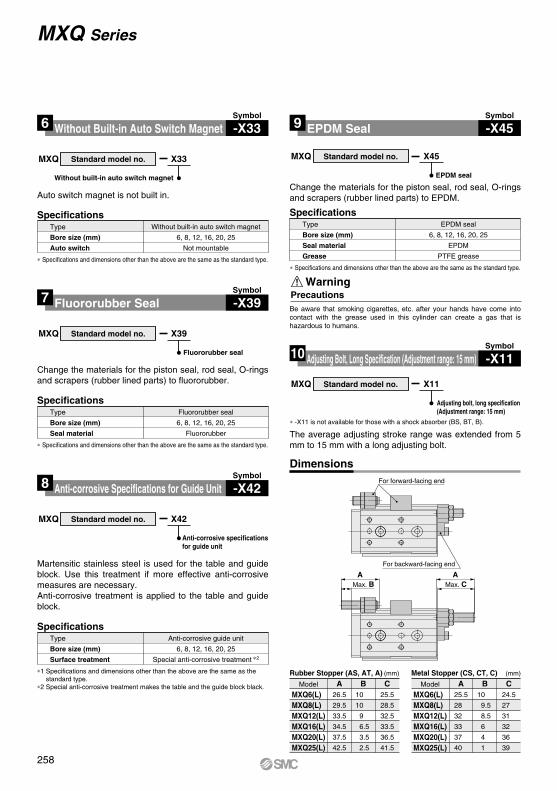
Max. CAA
Max. B
For forward-facing end
For backward-facing end
SpecificationsWithout built-in auto switch magnet
6, 8, 12, 16, 20, 25
Not mountable
Type
Bore size (mm)
Auto switch
MXQ X33
Without built-in auto switch magnet
∗ Specifications and dimensions other than the above are the same as the standard type.
Standard model no.
Symbol
Without Built-in Auto Switch Magnet6 -X33
Auto switch magnet is not built in.
SpecificationsEPDM seal
6, 8, 12, 16, 20, 25
EPDM
PTFE grease
Type
Bore size (mm)
Seal material
Grease
MXQ X45
EPDM seal
∗ Specifications and dimensions other than the above are the same as the standard type.
Standard model no.
Symbol
EPDM Seal9 -X45
Change the materials for the piston seal, rod seal, O-rings and scrapers (rubber lined parts) to EPDM.
SpecificationsFluororubber seal
6, 8, 12, 16, 20, 25
Fluororubber
Type
Bore size (mm)
Seal material
MXQ X39
Fluororubber seal
∗ Specifications and dimensions other than the above are the same as the standard type.
Standard model no.
Symbol
Fluororubber Seal7 -X39
Change the materials for the piston seal, rod seal, O-rings and scrapers (rubber lined parts) to fluororubber.
SpecificationsAnti-corrosive guide unit
6, 8, 12, 16, 20, 25
Special anti-corrosive treatment ∗2
Type
Bore size (mm)
Surface treatment
MXQ X42
Anti-corrosive specifications for guide unit
Standard model no.
Symbol
Anti-corrosive Specifications for Guide Unit8 -X42
Martensitic stainless steel is used for the table and guide block. Use this treatment if more effective anti-corrosive measures are necessary.Anti-corrosive treatment is applied to the table and guide block.
∗ -X11 is not available for those with a shock absorber (BS, BT, B).
The average adjusting stroke range was extended from 5 mm to 15 mm with a long adjusting bolt.
MXQ X11
Adjusting bolt, long specification(Adjustment range: 15 mm)
Standard model no.
Symbol
Adjusting Bolt, Long Specification (Adjustment range: 15 mm)10 -X11
Model
MXQ6(L)MXQ8(L)MXQ12(L)MXQ16(L)MXQ20(L)MXQ25(L)
(mm)
A26.5
29.5
33.5
34.5
37.5
42.5
B10
10
9
6.5
3.5
2.5
C25.5
28.5
32.5
33.5
36.5
41.5
Dimensions
Rubber Stopper (AS, AT, A)Model
MXQ6(L)MXQ8(L)MXQ12(L)MXQ16(L)MXQ20(L)MXQ25(L)
(mm)
A25.5
28
32
33
37
40
B10
9.5
8.5
6
4
1
C24.5
27
31
32
36
39
Metal Stopper (CS, CT, C)
PrecautionsWarning
Be aware that smoking cigarettes, etc. after your hands have come into contact with the grease used in this cylinder can create a gas that is hazardous to humans.
MXQ Series
∗1 Specifications and dimensions other than the above are the same as the standard type.
∗2 Special anti-corrosive treatment makes the table and the guide block black.
258

Max. CAA
Max. B
For forward-facing end
For backward-facing end
∗ -X12 is not available for the MXQ6.∗ -X12 is not available for those with a shock absorber (BS, BT, B).
The average adjusting stroke range was extended from 5 mm to 25 mm with a long adjusting bolt.
MXQ X12
Adjusting bolt, long specification(Adjustment range: 25 mm)
Standard model no.
Symbol
Adjusting Bolt, Long Specification (Adjustment range: 25 mm)11 -X12
Model
MXQ8(L)MXQ12(L)MXQ16(L)MXQ20(L)MXQ25(L)
(mm)
A39.5
43.5
44.5
47.5
52.5
B20
19
16.5
13.5
12.5
C38.5
42.5
43.5
46.5
51.5
Dimensions
Rubber Stopper (AS, AT, A)Model
MXQ8(L)MXQ12(L)MXQ16(L)MXQ20(L)MXQ25(L)
(mm)
A38
42
43
47
50
B19.5
18.5
16
14
11
C37
41
42
46
49
Metal Stopper (CS, CT, C)
Made to Order: Individual Specifications MXQ Series
259
MXH
MXS
MXQ
MXQ
MXF
MXW
MXJ
MXP
MXY
MTS
D-
-X
MXQ
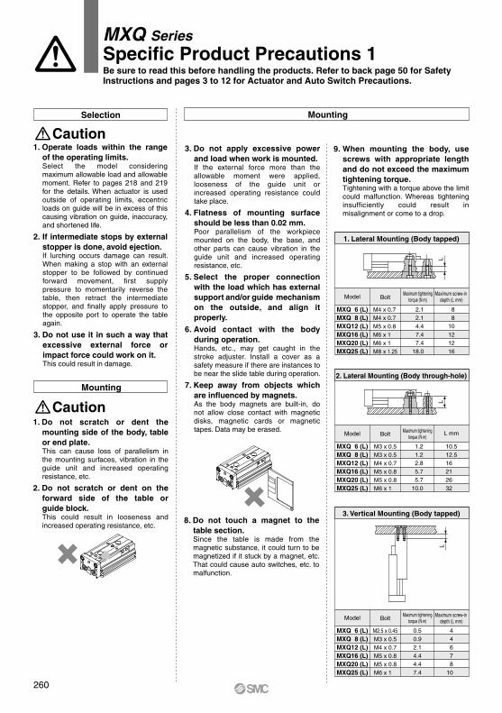
MountingSelection
Caution
Model
MXQ 6 (L)MXQ 8 (L)MXQ12 (L)MXQ16 (L)MXQ20 (L)MXQ25 (L)
Bolt
M4 x 0.7M4 x 0.7M5 x 0.8M6 x 1M6 x 1M8 x 1.25
2.1 2.1 4.4 7.4 7.418.0
8 810121216
1. Lateral Mounting (Body tapped)
Model
MXQ 6 (L)MXQ 8 (L)MXQ12 (L)MXQ16 (L)MXQ20 (L)MXQ25 (L)
Bolt
M3 x 0.5M3 x 0.5M4 x 0.7M5 x 0.8M5 x 0.8M6 x 1
1.2 1.2 2.8 5.7 5.710.0
10.512.516212632
2. Lateral Mounting (Body through-hole)
Model
MXQ 6 (L)MXQ 8 (L)MXQ12 (L)MXQ16 (L)MXQ20 (L)MXQ25 (L)
Bolt
M2.5 x 0.45M3 x 0.5M4 x 0.7M5 x 0.8M5 x 0.8M6 x 1
0.50.92.14.44.47.4
44678
10
3. Vertical Mounting (Body tapped)
LL
Caution
L
Mounting
1. Operate loads within the range of the operating limits.Select the model considering maximum allowable load and allowable moment. Refer to pages 218 and 219 for the details. When actuator is used outside of operating limits, eccentric loads on guide will be in excess of this causing vibration on guide, inaccuracy, and shortened life.
2. If intermediate stops by external stopper is done, avoid ejection.If lurching occurs damage can result. When making a stop with an external stopper to be followed by continued forward movement, first supply pressure to momentarily reverse the table, then retract the intermediate stopper, and finally apply pressure to the opposite port to operate the table again.
3. Do not use it in such a way that excessive external force or impact force could work on it.This could result in damage.
1. Do not scratch or dent the mounting side of the body, table or end plate.This can cause loss of parallelism in the mounting surfaces, vibration in the guide unit and increased operating resistance, etc.
2. Do not scratch or dent on the forward side of the table or guide block.This could result in looseness and increased operating resistance, etc.
3. Do not apply excessive power and load when work is mounted.If the external force more than the allowable moment were applied, looseness of the guide unit or increased operating resistance could take place.
4. Flatness of mounting surface should be less than 0.02 mm.Poor parallelism of the workpiece mounted on the body, the base, and other parts can cause vibration in the guide unit and increased operating resistance, etc.
5. Select the proper connection with the load which has external support and/or guide mechanism on the outside, and align it properly.
6. Avoid contact with the body during operation.Hands, etc., may get caught in the stroke adjuster. Install a cover as a safety measure if there are instances to be near the slide table during operation.
7. Keep away from objects which are influenced by magnets.As the body magnets are built-in, do not allow close contact with magnetic disks, magnetic cards or magnetic tapes. Data may be erased.
8. Do not touch a magnet to the table section.Since the table is made from the magnetic substance, it could turn to be magnetized if it stuck by a magnet, etc. That could cause auto switches, etc. to malfunction.
9. When mounting the body, use screws with appropriate length and do not exceed the maximum tightening torque.Tightening with a torque above the limit could malfunction. Whereas tightening insufficiently could result in misalignment or come to a drop.
Maximum tighteningtorque (N·m)
Maximum screw-in depth (L mm)
Maximum tighteningtorque (N·m)
Maximum screw-in depth (L mm)
MXQ SeriesSpecific Product Precautions 1Be sure to read this before handling the products. Refer to back page 50 for Safety Instructions and pages 3 to 12 for Actuator and Auto Switch Precautions.
L mmMaximum tighteningtorque (N·m)
260
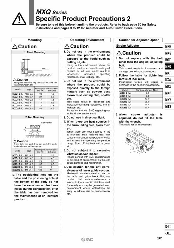
Mounting Operating Environment
CautionCaution
MXQ 6 (L)MXQ 8 (L)MXQ12 (L)MXQ16 (L)MXQ20 (L)MXQ25 (L)
M3 x 0.5M4 x 0.7M5 x 0.8M6 x 1M6 x 1M8 x 1.25
0.9 2.1 4.4 7.4 7.418.0
4.5 5.5 7.5 9.512.514.5
1. Front Mounting
MXQ 6 (L)MXQ 8 (L)MXQ12 (L)MXQ16 (L)MXQ20 (L)MXQ25 (L)
M3 x 0.5M3 x 0.5M4 x 0.7M5 x 0.8M5 x 0.8M6 x 1
1.2 1.2 2.8 5.7 5.710.0
3.5 4.3 5.5 6.5 9 11
2. Top Mounting
ModelMXQ 6 (L)MXQ 8 (L)MXQ12 (L)MXQ16 (L)MXQ20 (L)MXQ25 (L)
Tightening torque (N·m) 3.0 5.012.525.043.069.0
Caution for Adjuster Option
Caution
Stroke Adjuster
L
CautionIf long bolts are used, they can touch the table and cause malfunction, etc.
Model BoltMaximum tightening
torque (N·m)Maximum screw-in
depth (L mm)
If long bolts are used, they can touch the guide block and cause malfunction, etc.
Caution
Model BoltMaximum tightening
torque (N·m)Maximum screw-in
depth (L mm)
10. The positioning hole on the table and the positioning hole at the bottom of the body do not have the same center. Use these holes during reinstallation after the table has been removed for the maintenance of an identical product.
1. Do not use in the environment, where the product could be exposed to the liquid such as cutting oil, etc.Using in the environment where the product could be exposed to cutting oil, coolant or oil, etc. could result in looseness, increased operating resistance, or air leakage, etc.
2. Do not use in the environment, where the product could be exposed directly to the foreign matters such as powder dust, blown dust, cutting chip, spatter etc.This could result in looseness and increased operating resistance, and air leakage, etc.Please consult with SMC regarding use in this kind of environment.
3. Do not use in direct sunlight.4. When there are heat sources in
the surrounding area, block them off.When there are heat sources in the surrounding area, radiated heat may cause the product’s temperature to rise and exceed the operating temperature range. Block off the heat with a cover, etc.
5. Do not subject it to excessive vibration and/or impact.Please consult with SMC regarding use in this kind of environment, as this can cause damage and malfunction.
6. Use caution for the anti-corro-siveness of linear guide section.Martensitic stainless steel is used for the table and guide block. But, use caution that anti-corrosiveness is inferior to the austenitic stainless steel. Especially, rust may be generated in an environment where waterdrops are likely to adhere due to condensation, etc.
1. Do not replace with the bolt other than the original adjusting bolt.This could result in looseness and damage due to impact forces, etc.
2. Follow the table for tightening torque of lock nuts.Insufficient torque will cause a decrease in the positioning accuracy.
3. When stroke adjuster is adjusted, do not hit the table with the wrench.This could result in looseness.
L
Guide block
MXQ SeriesSpecific Product Precautions 2Be sure to read this before handling the products. Refer to back page 50 for Safety Instructions and pages 3 to 12 for Actuator and Auto Switch Precautions.
261
MXH
MXS
MXQ
MXQ
MXF
MXW
MXJ
MXP
MXY
MTS
D-
-X
MXQ

CautionRubber Stopper
Caution on Mounting Adjuster Option
CautionShock Absorber
Model
MXQ 6 (L)MXQ 8 (L)MXQ12 (L)MXQ16 (L)MXQ20 (L)MXQ25 (L)
0.5 0.9 2.1 4.4 7.018.0
M2.5 x 6M3 x 8M4 x 12M5 x 16M6 x 16M8 x 18
M2.5 x 8M3 x 10M4 x 12M5 x 16M6 x 16M8 x 18
Stroke adjuster at extension end (AS) Stroke adjuster at retraction end (AT)Body mounting section Table mounting section
M2.5 x 6M3 x 8
M4 x 10M5 x 12M5 x 14M6 x 18
Thread size Tightening torque (N·m) Thread size Tightening torque (N·m) Thread size Tightening torque (N·m) 0.5 0.9 2.1 4.4 7.018.0
0.50.92.14.44.47.0
Model
MXQ 6 (L)MXQ 8 (L)MXQ12 (L)MXQ16 (L)MXQ20 (L)MXQ25 (L)
0.5 0.9 2.1 4.4 7.018.0
M2.5 x 6M3 x 8M4 x 12M5 x 16M6 x 16M8 x 18
M2.5 x 8M3 x 10M4 x 12M5 x 16M6 x 20M8 x 20
Stroke adjuster at extension end (CS) Stroke adjuster at retraction end (CT)Body mounting section Table mounting section
M2.5 x 6M3 x 8M4 x 10M5 x 12M5 x 14M6 x 18
0.5 0.9 2.1 4.4 7.018.0
0.50.92.14.44.47.0
Model
MXQ 8 (L)MXQ12 (L)MXQ16 (L)MXQ20 (L)MXQ25 (L)
0.9 2.1 4.4 7.018.0
M3 x 12M4 x 12M5 x 16M6 x 18M8 x 18
M3 x 12M4 x 12M5 x 16M6 x 20M8 x 20
Shock absorber at extension end (BS) Shock absorber at retraction end (BT)Body mounting section Table mounting section
M3 x 8M4 x 10M5 x 12M5 x 14M6 x 18
0.9 2.1 4.4 7.018.0
0.92.14.44.47.0
CautionMetal Stopper
Caution
With Shock Absorber
Caution on Adjuster Option
Applicable size
MXQ 8 (L)MXQ12 (L)
Tightening torque (N·m)
1.67
3.14
10.8MXQ20 (L)MXQ25 (L)
MXQ16 (L)
Applicable sizeMXQ 8 (L)MXQ12 (L)MXQ16 (L)MXQ20 (L)MXQ25 (L)
Shock absorber modelRB0805RB0806RB1007RB1411RB1412
1. Allowable operating cycle under the specifications set in this catalog is shown below.1.2 million cycles RB082 million cycles RB10 to RB14
Note) Specified service life (suitable replacement period) is the value at room temperature (20 to 25°C). The period may vary depending on the temperature and other conditions. In some cases the absorber may need to be replaced before the allowable operating cycle above.
Caution
Service Life and ReplacementPeriod of Shock Absorber
1. Do not rotate the screw set on bottom of shock absorber.This is not an adjusting screw. Turning it could cause oil leakage.
2. Do not scratch the exposed portion of the piston rod.Durability could be degraded and lead to return defect.
Turning thebottom screw is not allowed.Piston rod
Damage is not allowed.
3. Shock absorber is considered a consumable component. When energy absorption is decreased, replace it.
1. Use caution that the length of the bolts for mounting on the body and the bolts for the table is different from each other in some models. Stroke adjuster at extension end (AS) of MXQ6 and 8 has the different length of a hexagon socket head cap screw for mounting on the body and on the table. Use sufficient care for mounting. If assembled by making an error in length, it could cause looseness or lead to malfunction.
2. Follow the table below for tightening torque of mounting bolts.Insufficient torque will cause a decrease in the positioning accuracy and lead to malfunction.
1. Use caution that the length of the bolts for mounting on the body and the bolts for the table is different from each other in some models. Shock absorber at extension end (BS) for MXQ20 and 25 has the different length of a hexagon socket head cap screw for mounting on the body and on the table. Use sufficient care for mounting. If assembled by making an error in length, it could cause looseness or lead to malfunction.
2. Follow the table below for tightening torque of mounting bolts.Insufficient torque will cause a decrease in the positioning accuracy and lead to malfunction.
Thread size Tightening torque (N·m) Thread size Tightening torque (N·m) Thread size Tightening torque (N·m)
1. Use caution that the length of the bolts for mounting on the body and the bolts for the table is different from each other in some models. Stroke adjuster at extension end (CS) of MXQ6, 8, 20 and 25 has the different length of a hexagon socket head cap screw for mounting on the body and on the table. Use sufficient care for mounting. If assembled by making an error in length, it could cause looseness or lead to malfunction.
2. Follow the table below for tightening torque of mounting bolts.Insufficient torque will cause a decrease in the positioning accuracy and lead to malfunction.
Thread size Tightening torque (N·m) Thread size Tightening torque (N·m) Thread size Tightening torque (N·m)
MXQ SeriesSpecific Product Precautions 3Be sure to read this before handling the products. Refer to back page 50 for Safety Instructions and pages 3 to 12 for Actuator and Auto Switch Precautions.
262

Caution
With End Lock
Caution on Handling Functional Option
How to Unlock the End Lock∗ Before proceeding, make sure that there is no residual air pressure.
(1) Push down the lock piston pin.(2) Slide the table forward.
Caution
With Buffer Mechanism
ModelMXQ 6 (L)MXQ 8 (L)MXQ12 (L)MXQ16 (L)MXQ20 (L)MXQ25 (L)
A2
2.545
5.510
B
3
W
Caution on Handling Symmetric Type
Caution
A
B
(2)
(1)
1. Use 2 position, 4 or 5 port solenoid valves.A malfunction may occur with a control circuit that exhausts from both ports, such as exhaust center 3 position valves.
Recommended pneumatic circuit
Air slide table
2. Be sure to use meter-out speed control valves.If it is used in meter-in speed control or without a speed controller, it may result in malfunction.
3. When releasing the end lock manually, be sure that air pressure is released.If the end lock is unlocked while the air pressure still remains, it will lead to damage a workpiece, etc. due to unexpected lurching.
1. It must be oriented as shown below.In horizontal operation, the buffer may travel the stroke length and activate the auto switch depending on the load and the speed. Therefore, adjust the speed according to the load.
2. Auto switch with buffer function: Refer to the following table for the proper mounting positions for detection at stroke end.
Normally OFFdetection
Normally ONdetection
∗ Adjust the auto switch position according to the load and the speed.
(mm)
1. Maintain a minimum spacing of at least 3 mm if standard type and symmetric type are used side by side.It malfunctions if standard type and symmetric type are used close side by side.
Vertical use
Horizontal use
Allow a space of 3 mm or more for a side by side mounting.
MXQ SeriesSpecific Product Precautions 4Be sure to read this before handling the products. Refer to back page 50 for Safety Instructions and pages 3 to 12 for Actuator and Auto Switch Precautions.
263
MXH
MXS
MXQ
MXQ
MXF
MXW
MXJ
MXP
MXY
MTS
D-
-X
MXQ