my latest fata airframe design research project current status overview 17th february 2017
TRANSCRIPT

Mr. Geoffrey Allen Wardle. MSc. MSc. FATA Wing Design Trade Study 2012-2019
FUTURE ADVANCED TECHNOLOGY AIRCRAFT (FATA) AIRFRAME
DEVELOPMENT STUDY PROGRESS OVERVIEW PRESENTATION.
By Mr. GEOFFREY ALLEN WARDLE. MSc. MSc. C.Eng. Snr MAIAA.
1

Mr. Geoffrey Allen Wardle. MSc. MSc. FATA Wing Design Trade Study 2012-2019
2
This is an overview covering my current private design trade studies into the incorporation of new
structural technologies and manufacturing processes into a future transport wing design, and the
incorporation of mission adaptive wing (MAW) technology for per review through the AIAA
This study has been undertaken after my 13 years at BAE SYSTEMS MA&I, in airframe design
development as a Senior Design Engineer, and my Cranfield University MSc in Aircraft Engineering
completed in 2007(part-time), and was commenced in 2012 and I aim to complete it at the end of
2019. This utilises knowledge and skills bases developed throughout my career in aerospace,
academic studies and new research material I have studied, to produce a report and paper
exploring the limits to which an airframe research project can be perused using a virtual tool set,
and how the results can be presented for future research and manufacturing. The toolsets used are
Catia V5.R20 for design / analysis / kinematics / manufacturing simulation: PATRAN / NASTRAN for
analysis of composite structures: AeroDYNAMIC™ for analysis of aircraft OML / Structural Loads /
performance. This work will also form the basis for a PhD proposal, it is the product of my own
research, and has not in any part been produced or conceptualised during my employment with
BAE SYSTEMS or company which is any part thereof.
Sections which are defined as in work Sections 14 through 17 will be presented on completion as
the overview is updated and in depth studies of some supporting sections will be moved to the
capability maintenance supporting presentations, and referenced as such.
This structured overview should be read in conjunction with the following LinkedIn presentations: -
(1) My Composite Design Capability Maintenance Examples: (2) New Metallic Design and FEA
Capability Maintenance Examples: (3) New Kinematics and Aircraft Assembly Robotics Study.
Overview of my current research activities in aircraft design for the FATA paper.

Mr. Geoffrey Allen Wardle. MSc. MSc. FATA Wing Design Trade Study 2012-2019
Section 1:- Overview of the FATA airframe design development study.
Section 2:- Benefits of Z- direction reinforcement in composite laminates:
Section 3:- PRSEUS Structural element design and processing:
Section 4:- Overall loading on transport aircraft primary structures:
Section 5:- Structural design philosophies employed in the design of wing components:
Section 6:- Roll and layout of large aircraft wing structural members:
Section 7:- The design and structural layout of FATA wing:
Section 8:- The design and structural layout of the FATA fuselage (in work):
Section 9:- The design and structural layout of the FATA empennage (in work):
Section 10:- Assembly of baseline aircraft wing torsion box structural members:
Section 11:- Robotic assembly in the development of the Baseline wing (see also Robotic Kinematic for
FATA wing Study LinkedIn presentation):
Section 12:- Integration of baseline and developed aircraft main landing gear:
Section 13:- Integration of baseline and future concept engines:
Section 14:- FATA baseline airframe structural analysis and component sizing (in work):
Section 15:- FATA baseline airframe systems integration (in work):
Section 15:- FATA PRSEUS developed airframe structural layout and sizing analysis (in work):
Section 16:- FATA PRSEUS developed airframe systems integration (in work):
Section 17:- FATA MAW control surface integration (in work).
ONLY WORK FROM REFERENCED STUDIES MAY BE REPRODUCED WITHOUT EXPRESS PERMISSION
OF MYSELF AND THE AIAA.
3
Contents of this FATA study overview presentation.

Mr. Geoffrey Allen Wardle. MSc. MSc. FATA Wing Design Trade Study 2012-2019
Currently I am conducting a conceptual design research into the application the Future Integrated
Structure (FIS) technology PRSEUS (using NASA/TM-2009-215955 (ref 1) and NASA/CR-2011-
216880 (ref 2), as my starting point) and mission adaptive flight control surfaces, to future large
transport aircraft, as detailed in charts 1 to 5, chart 6 shows the projected baseline operational
profile used in loads and fuel tank sizing calculations. This is a technical report for per review
through the AIAA, future PRSEUS studies and the work breakdown are shown in charts 7,8,9.
The reference baseline aircraft selected is for a CFC twin engine 250-300 seat class aircraft design
of conventional configuration. Table 1 presents design data and figure 1(a) illustrates the
configuration of the Baseline FATA aircraft, and figure 1(b) shows the supercritical airfoil selected
the FATA aircraft. This conventional design using the current materials technology shown in figure
2, and will be compared with an improved baseline design incorporating PRSEUS (FIS) technology
figures 5, 6, 7 and 8, and Mission Adaptive Wing MAW Control surfaces, figures 9 and 10, to be
designed using Catia V5.R20, to determine the structural / weight / and aerodynamic benefits at the
trade study level and finally more advanced aircraft design configurations will be used to determine
future potential applications. The study consists of three phases:- (1) The overall airframe
configuration design and parametric analysis using both classical analysis and the Jet306 /
AeroDYNAMIC V2.08 analysis tool set based on my Cranfield MSc: (2) The second is major
structural wing component layout of the airframe initial structure with preliminary systems
integration, and using Cranfield University methods and Catia V5.R20 GSA for structural sizing. (3)
The final design study for both versions of the wing reference and new build will consist of
parametric analysis, initial optimisation and structural layout and analysis and constitutes a
feasibility study proposal to determine the benefits, and constraints on such an application.
Section 1:- Overview of the FATA airframe design development study.
4

Mr. Geoffrey Allen Wardle. MSc. MSc. FATA Wing Design Trade Study 2012-2019
IMPERIAL DATA. METRIC DATA.
Wing Span (ft / in) 231 / 3.3 Wing Span (m) 70.52
Length (ft / in) 240/88 Length (m) 75.88
Wing Area (sq ft) 4,375.49 Wing Area (sq m) 406.481
Fuselage diameter (in) 235.83 Fuselage diameter (m) 5.99
Wing sweep angle 35° Wing sweep angle 35°
Fuselage Length (ft /in) 244 / 3.8 Fuselage Length 74.47
Engine number / type 2 X RR Trent XWB Engine number / type 2 X RR Trent XWB
T-O thrust (lb) 83,000 T-O thrust (kN) 369.0
Max weight (lb) 590,829 Max weight (tonnes) 268.9
Max Landing (lb) 451,940 Max Landing (tonnes) 205.0
Max speed (mph) 391 Max speed (km/h) 630
Mach No 0.89 Mach No 0.89
Range at OWE (miles) 9,631 Range at OWE (km) 15,500
Cruise Altitude (ft) 45,000 Cruise Altitude (m) 13,716
5
Table 1:- Baseline Aircraft Data for the AIAA study (highlighted data used for baseline).

Mr. Geoffrey Allen Wardle. MSc. MSc. FATA Wing Design Trade Study 2012-2019
Figure 1(a):- Overall configuration and dimensions of the FATA baseline aircraft.
70.52m (231ft 3.3in) Code F
18.34m (60ft 7in)
11.51m (37ft 1.6in)
30.58m (100ft 3.8in)
75.87m (248ft 1.3in) Code E
74.47m (244ft 3.8in)
34.45m (113ft 2.4in)
75.27m (246ft 10.7in)
Fuselage sized for
twin aisle 9 abreast
2 LD-3 containers
5.99m (235.85in) Section on „A‟
„A‟
„A‟
17.85m
(58ft 4.6in)
6

Mr. Geoffrey Allen Wardle. MSc. MSc. FATA Wing Design Trade Study 2012-2019
7
Figure 1(b):- Aerofoil profile selection based on C-17 transport.
Figure 2a/b:- Flow fields around 1(a) conventional aerofoil 1(b) supercritical aerofoil.
Figure 2(a) Figure 2(b)
Figure 2(c):- Sketches of root NASA SC(2) 0414 and tip NASA SC(2) 0410 aerofoil profiles.

Mr. Geoffrey Allen Wardle. MSc. MSc. FATA Wing Design Trade Study 2012-2019
8
AL/Li Alloy
CFRP MONOLITIC
CFRP SANDWICH
TITANIUM
QUARTZ GLASS
By weight percentage.
Composites 50%
Titanium 15%
Steel 10%
Other 5%
AIRBUS A350-900 XWB Airframe.
BOEING 787-8 Airframe.
Figure 2:- Materials utilization on current generation commercial airframes.
Mr. Geoffrey Allen Wardle. MSc. MSc. FATA Wing Design Trade Study 2012-2019
My current research activities in aircraft design for the FATA project.
Aircraft design studies are a detailed and iterative procedure involving a variety of theoretical and
empirical equations and complex parametric studies. Although aircraft specifications are built
around the basic requirements of payload, range and performance, the design process also
involves meeting overall criteria in terms of, for example, take-off weights, airport constraints,
maintainability and operating cost.
The main issues come from the interdependency of all of the design variables involved, in
particular the dependency relationship between wing area, engine thrust, and take-off weight which
are complex and often require an initial study of existing aircraft designs to get a first impression of
the practicality of the proposed design, this is the process adopted by myself in designing the
reference wing based upon the most recent fielded technology. An aircraft design trade study can
be considered to two phases:- the initial „first approximation‟ methodology: followed by „parametric
analysis‟ stages, although in practice the process is more iterative than purely sequential. Table 2
shows the basic steps to generate configuration data for AeroDYNAMIC MDO toolset, with some
general rules of thumb, based on concept design experience.
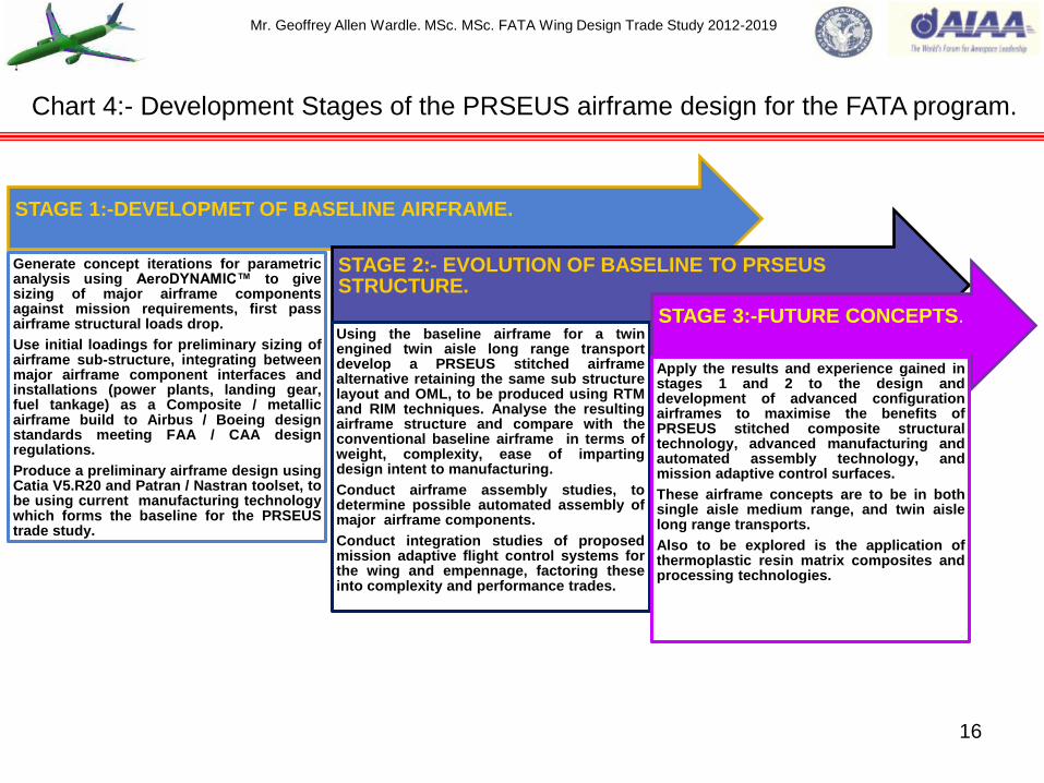
Chart 4 illustrates the development stages, for evaluation the Baseline, PRSEUS airframes and
future concepts employing this technology. The AeroDYNAMIC™ toolset was used to produce
parametric study plots showing the bounds of the design which fitted the chosen design criteria and
are incorporated in the full study paper.
9
Mr. Geoffrey Allen Wardle. MSc. MSc. FATA Wing Design Trade Study 2012-2019
Requirements Cascade.
Starting with the customer needs, Top Level Aircraft Requirements (TLAR) are formulated
e.g.:- Number of passengers / seats: Weight target: Cargo / baggage payload: Range: etc.
These requirements were broken down into requirements for the Major Airframe Components
of the aircraft Top Level Structural Requirements Studies (TLSRS) e.g. for:-
Fuselage:
Wing:
Empennage:
Systems.
These were further broken down to Section Level Requirements (SLR) for each structural
component e.g. for:-
Skins:
Stringers:
Floor Beams.
All of these are governed by Design Principles and Standards for which for commercial aircraft I
have researched the AIAA ARC :- (Reference Structural Design Principles and Systems
Installation Design Principles). For Airbus there are the RSDP which are Design Principles
for airframe structural design, and SIDP which are Design Principles for designing and
integrating aircraft systems.
10
My requirements research breakdown for the FATA aircraft design project.
Mr. Geoffrey Allen Wardle. MSc. MSc. FATA Wing Design Trade Study 2012-2019
11
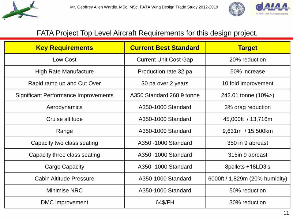
FATA Project Top Level Aircraft Requirements for this design project.
Key Requirements Current Best Standard Target
Low Cost Current Unit Cost Gap 20% reduction
High Rate Manufacture Production rate 32 pa 50% increase
Rapid ramp up and Cut Over 30 pa over 2 years 10 fold improvement
Significant Performance Improvements A350 Standard 268.9 tonne 242.01 tonne (10%>)
Aerodynamics A350-1000 Standard 3% drag reduction
Cruise altitude A350-1000 Standard 45,000ft / 13,716m
Range A350-1000 Standard 9,631m / 15,500km
Capacity two class seating A350 -1000 Standard 350 in 9 abreast
Capacity three class seating A350 -1000 Standard 315in 9 abreast
Cargo Capacity A350 -1000 Standard 8pallets +18LD3‟s
Cabin Altitude Pressure A350-1000 Standard 6000ft / 1,829m (20% humidity)
Minimise NRC A350-1000 Standard 50% reduction
DMC improvement 64$/FH 30% reduction

Mr. Geoffrey Allen Wardle. MSc. MSc. FATA Wing Design Trade Study 2012-2019
12
Table 2:- Example of the „first approximation‟ methodology used in the FATA study.
Estimated parameter. Basic relationship. Rule of thumb.
(1) Estimate wing loading
W/S.
W/S = 0.5 pV² C˪ (in the
„approach‟ condition).
Approach speed lies between 1.45 and 1.62 Vstall.
Approach C˪ lies between C˪max /2.04 and C˪max /2.72
(2) Check C˪ in cruise. C˪ = 0.98(W/S) /q
Where q = 0.5 pV² .
C˪ generally lies between 0.44 and 0.5
(3) Check gust response
at cruise speed.
Gust response parameter
α1wb .AR / (W/S)
α1wb is the wing body lift curve slope obtained from
data sheets.
(4) Estimate size. Must comply with take-off
and climb performance.
The aircraft type considered i.e. long range transport
have engines sized for top of the climb requirements.
(5) Estimate take-off wing
loading and T/W ratio as
a function of C˪V2
s =kM²g²/(SwT. C˪V2 )
1.7< C˪max < 2.2 and 1.18< C˪V2 <1.53
(6) Check the capability
to climb (gust control) at
initial cruise altitude.
17< L/D < 21 in the cruise for most civil airliners.
(7) Estimate take-off
mass.
MTO = ME + MPAL + Mf 0.46< OEM / MTOM <0.57

Mr. Geoffrey Allen Wardle. MSc. MSc. FATA Wing Design Trade Study 2012-2019
13
Chart 1:- My current research activity for aircraft design trade studies FATA project.
The development and application of
advanced structural concepts, and
mission adaptive control surfaces to
commercial aircraft. Estimated at:-
6,240hrs (15 hour weeks over 8 years)
Work book 1:- Composite airframe design
and manufacture incorporating Catia
V5.R20. (exercises vertical tail fighter a/c
design / commercial aircraft vertical tail
design) COMPLETED.
Work book 2:- FEA using Catia V5.R20.
(exercises airframe structural component
design and analysis) COMPLETED.
Work book 3:- Control surface kinematics
Catia V5.R20. (exercises airframe flap
deployment analysis) COMPLETED.
Major structural layout:- Based on
Cranfield MSc Aircraft Engineering
modules using Catia V5.R20 as tool
set.
Defining airframe study concept:- MSc
Aircraft Engineering modules using
Catia V5.R20 as tool set and
AeroDYNAMIC V3 MSc / BAE skills
sets.
Major structural loads analysis and
component sizing:- Based on Cranfield
MSc Aircraft Engineering modules using
Catia V5.R20 as tool set.

Mr. Geoffrey Allen Wardle. MSc. MSc. FATA Wing Design Trade Study 2012-2019
14
DETERMINE AIRFRAME CONFIGURATION.
DEVELOP BASELINE STRUCTURAL LAYOUT
Wing size, sub structure layout, control surface
layout, interfaces and LG / fuel tankage integration.
Fuselage diameter, internal structural layout plus
cutouts, and structural interfaces with the wing,
empennage and LG.
Empennage size, structural internal layout, control surface layout and
sizing, interfaces with surfaces and fuselage.
DETERMINE STRUCTURAL LOADING AND LOAD
PATHS
Structural sizing of all major airframe components.
Detailed structural analysis of selected
airframe components.
Chart 2:- Activity dependency for the design trade studies of the FATA airframe.

Mr. Geoffrey Allen Wardle. MSc. MSc. FATA Wing Design Trade Study 2012-2019
15
Chart 3:- Phases of the FATA airframe PRSEUS design trade study program.
Work book 1:- Composite airframe design
Work book 2:- GSA airframe design
Phase 1:- Baseline composite / metallic wing
box, and wing / fuselage and empennage
layout design structural component sizing.
Baseline composite and metallic wing /
fuselage / empennage design structural /
weight analysis.
Work book 3:- Control surface kinematic
design analysis and sizing.
Phase 2:- Advanced concept composite
PRSEUS wing / fuselage and empennage
layout design structural component sizing.
Phase 1:- Baseline control surface design,
structural sizing and operational analysis.
Advanced FATA concept composite PRSEUS
Airframe design Wing: Fuselage: Empennage
conduct structural / weight analysis.
Phase 3:- FATA concept full composite
PRSEUS Airframe layout, Landing gear,
and MAW control surface integration,
design structural component sizing and
weight analysis.
Phase 2:- MAW control surface design
trades, structural sizing, weight and
operational analysis.
Mr. Geoffrey Allen Wardle. MSc. MSc. FATA Wing Design Trade Study 2012-2019
STAGE 1:-DEVELOPMET OF BASELINE AIRFRAME.
Generate concept iterations for parametric analysis using AeroDYNAMIC™ to give sizing of major airframe components against mission requirements, first pass airframe structural loads drop.
Use initial loadings for preliminary sizing of airframe sub-structure, integrating between major airframe component interfaces and installations (power plants, landing gear, fuel tankage) as a Composite / metallic airframe build to Airbus / Boeing design standards meeting FAA / CAA design regulations.
Produce a preliminary airframe design using Catia V5.R20 and Patran / Nastran toolset, to be using current manufacturing technology which forms the baseline for the PRSEUS trade study.
STAGE 2:- EVOLUTION OF BASELINE TO PRSEUS STRUCTURE.
Using the baseline airframe for a twin engined twin aisle long range transport develop a PRSEUS stitched airframe alternative retaining the same sub structure layout and OML, to be produced using RTM and RIM techniques. Analyse the resulting airframe structure and compare with the conventional baseline airframe in terms of weight, complexity, ease of imparting design intent to manufacturing.
Conduct airframe assembly studies, to determine possible automated assembly of major airframe components.
Conduct integration studies of proposed mission adaptive flight control systems for the wing and empennage, factoring these into complexity and performance trades.
STAGE 3:-FUTURE CONCEPTS.
Apply the results and experience gained in stages 1 and 2 to the design and development of advanced configuration airframes to maximise the benefits of PRSEUS stitched composite structural technology, advanced manufacturing and automated assembly technology, and mission adaptive control surfaces.
These airframe concepts are to be in both single aisle medium range, and twin aisle long range transports.
Also to be explored is the application of thermoplastic resin matrix composites and processing technologies.
16
Chart 4:- Development Stages of the PRSEUS airframe design for the FATA program.

Mr. Geoffrey Allen Wardle. MSc. MSc. FATA Wing Design Trade Study 2012-2019
17
Chart 5:- Design Trade Study Project Milestones for the FATA Project.
0% 10% 20% 30% 40% 50% 60% 70% 80% 90% 100%
2011
2012
2013
2014
2015
2016
2017
2018
2019
MILESTONE % COMPLETED.
PR
OJ
EC
T Y
EA
R.
ADVANCED AIRFRAME CONCEPT DESIGN STUDY MILESTONES.
Phase 3
Phase 2
Phase 1
Workbook 3
Workbook 2
Workbook 1
Mr. Geoffrey Allen Wardle. MSc. MSc. FATA Wing Design Trade Study 2012-2019
18
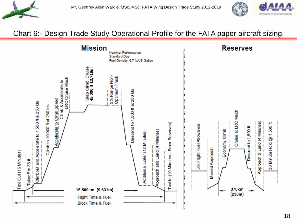
Chart 6:- Design Trade Study Operational Profile for the FATA paper aircraft sizing.
15,500km (9,631m) 370km
(230m)
45,0
00 f
t 13,7
16m

Mr. Geoffrey Allen Wardle. MSc. MSc. FATA Wing Design Trade Study 2012-2019
19
Chart 7:- My Future Advanced Technology Baseline Aircraft “Tube and Wing” 2030.
Composite Wings and
Empennage applied PRSEUS
stitched composite
technology.
All electric control system with
MAW technology and advanced
EHA actuation system.
Hybrid Laminar Flow
Control on wing
upper surface.
Composite Fuselage
applied PRSEUS stitched
composite stringers.
Natural Laminar
Flow on nacelles.
Advanced
Engines.
Variable Trailing
Edge Camber.
Wing aspect ratio >10.
Riblets on fuselage.
Hybrid Laminar Flow Control
on Vertical and Horizontal tails .
SOFC/GT Hybrid APU.
Positive control winglets.
HT Thermoplastic
composite engine pylons.
Thermoplastic composite
fuselage frames.
Thermoplastic composite
Belly Fairing.
Mr. Geoffrey Allen Wardle. MSc. MSc. FATA Wing Design Trade Study 2012-2019
20
PRSEUS stitched
composite technology
empennage 2016-2018.
PRSEUS stitched composite
technology wing in work
2013-2017.
Automated Assembly of wing
structure fall 2016-2017.
Thermoplastic composite
fuselage frames 2017-2019.
Positive control winglets
2016-2017.
Composite Fuselage applied
PRSEUS stitched composite
stringers 2017-2019.
Thermoplastic composite
Belly Fairing 2017-2019. HT Thermoplastic
composite engine pylons
proposed fall 2016-2018.
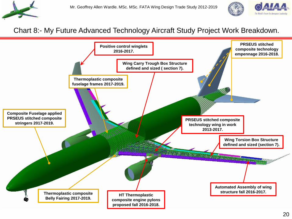
Chart 8:- My Future Advanced Technology Aircraft Study Project Work Breakdown.
Wing Carry Trough Box Structure
defined and sized ( section 7).
Wing Torsion Box Structure
defined and sized (section 7).

Mr. Geoffrey Allen Wardle. MSc. MSc. FATA Wing Design Trade Study 2012-2019
21
Chart 9:- My Future Advanced Technology Aircraft Fuselage Study Baseline .
Composite Fuselage applied
PRSEUS stitched composite
stringers 2017-2019.
Thermoplastic composite
fuselage frames 2017-2019.
Stringer Co-Bonded to Skin.
Clip PPS Thermoplastic Matrix composite with quasi-isotopic layup
Frame CFRP prepreg.
80mm
120mm
Frame lay up [30º/90º/-30º]
with 0º reinforcement.
The proposed fuselage PRSEUS and thermoplastic application design and structural
development will use either Airbus or Boeing composite fuselage structural design
philosophies as the baseline against which PRSEUS improvements will be assessed.
AIRBUS:- A350 XWB
Boeing:- B787

Mr. Geoffrey Allen Wardle. MSc. MSc. FATA Wing Design Trade Study 2012-2019
Conventional laminated two-dimensional composites are not suitable for applications where trough
thickness stresses may exceed the (low) tensile strength of the matrix (or matrix / fibre bond) and in
addition, to provide residual strength after anticipated impact events, two–dimensional laminates
must therefore be made thicker than required for meeting strength requirements. The resulting
penalties of increased structural weight and cost provide impetus for the development of more
damage-resistant and tolerant composite materials and structures. Considerable improvements in
damage resistance can be made using tougher thermoset or thermoplastic matrices together with
optimized fibre / matrix bond strength. However, this approach can involve significant costs, and the
improvement that can be realized are limited. There are also limits to the acceptable fibre / matrix
bond strength because high bond strength can lead to increased notch-sensitivity.
An alternative and potentially more efficient means of increasing damage resistance and through-
thickness strength is to develop a fibre architecture in which a proportion of fibers in the composite
are orientated in the z-direction. This fibre architecture can be obtained, for example, by three-
dimensional weaving or three-dimensional breading.
However a much simpler approach is to apply reinforcement to a conventional two-dimensional
fibre configuration by stitching: although, this dose not provide all of the benefits of a full three-
dimensional architecture. In all of these approaches, a three dimensional preform produced first
and converted into a composite by either RTM / VARTM, or CAPRI (see later in this presentation).
Even without the benefits of three-dimensional reinforcement, the preform approach has the
important advantage that it is a comparatively low-cost method of manufacturing composite
components compared with conventional laminating procedures based on pre-preg.
22
Section 2:- The structural benefits of 3-D stitched and pinned composites.

Mr. Geoffrey Allen Wardle. MSc. MSc. FATA Wing Design Trade Study 2012-2019
23
The structural benefits of 3-D stitched and pinned composites over conventional laminates.
(a) Lock stitch (b) Modified Lock stich (c) Chain stitch
Needle
Thread
Bobbin
Thread
Needle
Thread
Bobbin
Thread
Figure 3:-Schematic diagram of three commonly used stitches for 3-D reinforcement.
Indeed, preforms for resin transfer molding (RTM) and other liquid molding techniques are often
produced from a two dimensional fibre configuration by stitching or knitting.
Stitching:- This is best applied using an industrial-grade sewing machine where two separate
yarns are used. For stitching composites, the yarns are generally aramid (Kevlar), although other
yarns such as glass, carbon, and nylon have also been used. A needle is used to perforate a pre-
preg layup or fabric preform, enabling the insertion of a high–tensile-strength yarn in the thickness
direction. In the case of the PRSEUS process a Vectran thread impregnated with epoxy resin is
used. The yarn, normally referred to as the needle yarn, is inserted from the top of the layup /
preform, which is held in place using a presser foot. When the yarn reaches the bottom of the
layup / preform it is caught by another yarn, called the bobbin yarn, before it re-enters the layup /
preform as the needle is withdrawn from the layup / preform, thus forming a full stich. The layup /
preform, is then advanced a set distance between the presser foot and a roller mechanism before
the needle is used to apply the next stitch. This process is repeated to form a row of stitches.
Figure 3 shows the various types of stitches commonly used to create z-direction reinforcement.

Mr. Geoffrey Allen Wardle. MSc. MSc. FATA Wing Design Trade Study 2012-2019
Among the three stitches shown in figure 3, the modified lock stitch in which the crossover knot
between the bobbin and needle threads is positioned at either laminate surface, to minimize in-
plane fibre distortion is considered the best, and is the preferred method. Apart from improving z-
direction properties, stitching serves as an effective means of assembling preforms of dry two-
dimensional tape or cloth, for example, attaching stringers to skin preforms, that can then be
consolidated using liquid molding.
Mechanical Properties Improvements: - (1) Out-of-Plane properties are significantly improved by
stitching, increasing the interlaminar delamination resistance for fibre reinforced plastic laminates
under mode I (tensile loading KIC) and to a lesser extent mode II (shear loading KIIC) loadings. In
order achieve this, the stiches need to remain intact for a short distance behind the crack front and
restrict any effort to extend the delamination crack. With such enhanced fracture toughness stitched
laminates have better resistance to delamination cracking under low energy, high energy and
ballistic impacts as well as under dynamic loading by explosive blast effects. Stitched laminates
also possess higher post-impact residual mechanical properties than non-stitched laminates.
Studies (ref 6) have shown that the effectiveness of stitching for improving residual strength is
dependent on factors such as the stitch density, stitch type, and stitch thread. Although the best
improvement in compression post impact strength has been found in relatively thick laminates, and
though similar improvements in residual strength have been observed in toughened matrix
laminates the latter is two to three times more expensive than stitching. Stitching also improves
shear lap joint strength under both static and cyclic loading, largely due to reducing the peel
stresses. Stitching can delay the initiation of disbonds and provide load transfer even after bond line
failure. Stitching is also effective in suppressing delamination due to free edge effects. 24
The structural benefits of 3-D stitched and pinned composites over conventional laminates.

Mr. Geoffrey Allen Wardle. MSc. MSc. FATA Wing Design Trade Study 2012-2019
(2) In-Plane properties of a two dimensional composite laminate can also be affected by stitching,
due the introduction of defects in the final laminate during needle insertion or as a result of
presence of the stitch yarn in the laminate. These defects may occur in various forms including
broken fibres, resin-rich regions, and fine scale resin cracking. Fibre misalignment however
appears to have the greatest detrimental effect on mechanical properties, particularly under in
plane tensile and compressive loading.
In order to keep defects resulting from stitching to a minimum, careful selection and control of the
stitching parameters (including:- yarn diameter: yarn tension: yarn material: stitch density: etc.), are
essential. Analysis of the effects of stitching on in-plane material properties of two dimensional
composite laminates in general have been somewhat inconclusive (ref 6), with studies showing that
stiffness and strength of the composites under tensile and compressive loadings can be either
degraded, unchanged, or improved with stitching, depending on the type of composite, the stitching
parameter, and the loading condition. The improvements in tensile and compressive stiffness have
been attributed to the increase in fibre / volume fraction that results from a compaction of the in-
plane fibres by stitching. The enhancement in compressive strength is attributed to the suppression
of delamination's. The stiffness in tension and compression is mainly degraded when in-plane fibres
are misaligned by the presence of the stitching yarn in their path. Premature compressive failure
can result from the stitching being too taut, which in turn can cause excessive crimping of the in-
plane fibres. Conversely, insufficient tension on the stitching yarn can cause the stitches to buckle
under consolidation pressures and render them ineffective as a reinforcement in the thickness
direction, which was the original intention. Tensile strength however is normally degraded due to
fibre fractures arising from damage inflicted by the stitching needle. 25
The structural benefits of 3-D stitched and pinned composites over conventional laminates.

Mr. Geoffrey Allen Wardle. MSc. MSc. FATA Wing Design Trade Study 2012-2019
Enhancements of tensile strength, which has been observed, is attributed to an increase in fibre /
volume fraction resulting from compaction of the in-plane fibres by the stitching. The in-plane
fatigue performance is also considered to be degraded due to the same failure mechanisms
responsible for degradation of their corresponding static properties.
Finally, it appears that the flexural and interlaminar shear strengths of two-dimensional laminates
may also be degraded, unchanged, or improved with stitching. In general, the conflicting effects of
stitching, in increasing fibre content and suppressing delamination, on one hand, and introducing
misalignment and damage to in-plane fibres on the other, are possibly responsible for the reported
behaviors.
Z-Pinning:- This is a simple method of applying three-dimensional reinforcement with several
benefits over stitching. However, unlike stitching, z-pinning cannot be used to make preforms and
therefore is included here for completeness. In the z-pinning process, thin rods are inserted at right
angles into a two-dimensional carbon / epoxy composite laminate, either before or during
consolidation. The z-rods can be metallic, usually titanium, or composite, usually carbon / epoxy,
and these are typically between 0.25mm (0.0098 inch) and 0.5mm (0.0197 inch) in diameter.
These rods are held with the required pattern and density in a collapsible foam block that provides
lateral support, this prevents the rods from buckling during insertion and allows a large number of
rods to be inserted in one operation. The z-rods are typically driven into the two-dimensional
composite by one of two methods as shown in figure 4. The first method (figure 4(a)) involves
placing the z-rod laden foam on top of an uncured pre-preg and autoclave curing. During the cure,
the combination of heat and pressure compacts the collapsible foam layer, driving the rods
orthogonally into the composite. 26
The structural benefits of 3-D stitched and pinned composites over conventional laminates.

Mr. Geoffrey Allen Wardle. MSc. MSc. FATA Wing Design Trade Study 2012-2019
When curing is completed, the residual foam preform is then removed and discarded, and the z-
rods sitting proud of the surface of the cured laminate are sheared away using a sharp knife.
The second method uses a purpose built ultrasonic insertion transducer to drive the z-rods into the
two-dimensional composite and is shown schematically in figure 4(b). This is a two stage process,
and during the first stage the preform is only partially compacted using the ultrasonic insertion
transducer, and thus the z-rods are not fully inserted. The residual foam is then removed, and a
second insertion stage is carried out with the ultrasonic insertion transducer making a second pass
to complete the insertion of the z-rods. If the z-rods are not flush with the part surface, the excess is
sheared away. In principle, the part to be z-pinned could take on any shape provided there is an
appropriate ultrasonic insertion transducer. Research indicates that the ultrasonic insertion
technique can be used to insert metallic pins into cured composites for the repair of delamination's,
although a considerable amount of additional damage to the parent material results and further
trade studies are required to determine its true viability.
Of the two z-pinning insertion methods the vacuum bag method is more suitable when a large or
relatively flat and unobstructed area is to be z-pinned. The ultrasonic method is more suitable for z-
pinning localized or difficult to access areas by configuring and shaping an appropriate ultrasonic
insertion transducer.
Mechanical Properties Improvements: - (1) Out-of-Plane properties indicate a significant
improvement in both mode I (tensile loading KIC) and mode II (shear loading KIIC) fracture
toughness, achieved through z-pinning based on published data, which would translate into
superior damage resistance and tolerance, as well as improved skin stiffener pull out properties. 27
The structural benefits of 3-D stitched and pinned composites over conventional laminates.

Mr. Geoffrey Allen Wardle. MSc. MSc. FATA Wing Design Trade Study 2012-2019
28
Figure 4 (a)/(b):- Z-Pinning process an alternative to stitching.
TOOL
Vacuum Bag
Prepreg Composite
Z-Fibre Preform
TOOL
PRESSURE
TOOL
Remove & Discard Foam
Cure Z-Pinned Composite
Stage 1:- Place Z-Fibre Preform on top of Prepreg and then enclose in vacuum
bag.
Stage 2:- Standard cycle or debulk cycle, heat and pressure compact preform
foam, forcing the Z-pins into the Prepreg composite.
Stage 3:- Remove compacted preform foam and discard Finish with cured Z-
pinned composite.
Figure 4(a). Figure 4(b).
Remove Used
Preform
Uncured Composite
Z-Fiber Preform
Ultrasonic Insertion Transducer
(a) Primary insertion stage and residual preform removal.
(b) Secondary insertion stage.
Mr. Geoffrey Allen Wardle. MSc. MSc. FATA Wing Design Trade Study 2012-2019
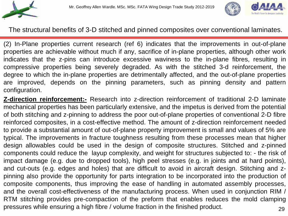
(2) In-Plane properties current research (ref 6) indicates that the improvements in out-of-plane
properties are achievable without much if any, sacrifice of in-plane properties, although other work
indicates that the z-pins can introduce excessive waviness to the in-plane fibres, resulting in
compressive properties being severely degraded. As with the stitched 3-d reinforcement, the
degree to which the in-plane properties are detrimentally affected, and the out-of-plane properties
are improved, depends on the pinning parameters, such as pinning density and pattern
configuration.
Z-direction reinforcement:- Research into z-direction reinforcement of traditional 2-D laminate
mechanical properties has been particularly extensive, and the impetus is derived from the potential
of both stitching and z-pinning to address the poor out-of-plane properties of conventional 2-D fibre
reinforced composites, in a cost-effective method. The amount of z-direction reinforcement needed
to provide a substantial amount of out-of-plane property improvement is small and values of 5% are
typical. The improvements in fracture toughness resulting from these processes mean that higher
design allowables could be used in the design of composite structures. Stitched and z-pinned
components could reduce the layup complexity, and weight for structures subjected to: - the risk of
impact damage (e.g. due to dropped tools), high peel stresses (e.g. in joints and at hard points),
and cut-outs (e.g. edges and holes) that are difficult to avoid in aircraft design. Stitching and z-
pinning also provide the opportunity for parts integration to be incorporated into the production of
composite components, thus improving the ease of handling in automated assembly processes,
and the overall cost-effectiveness of the manufacturing process. When used in conjunction RIM /
RTM stitching provides pre-compaction of the preform that enables reduces the mold clamping
pressures while ensuring a high fibre / volume fraction in the finished product.
29
The structural benefits of 3-D stitched and pinned composites over conventional laminates.

Mr. Geoffrey Allen Wardle. MSc. MSc. FATA Wing Design Trade Study 2012-2019
30
The PRSEUS structural concept illustrated in figures 5-7 is seen as the answer to the HWB
fuselage pressure and bending load issues that have held back the development of this aircraft
type. This study proposes to examine the feasibility of using the same structural concept to reduce
the wing rib structure and composite skin thickness / weight in a large transport aircraft wing.
As conceived in NASA/CR-2011-216880, the PRSEUS panels were designed as a bi-directionally
stiffened panel design, to resist loading where the span wise wing bending are carried by the frame
members (like skin / stiffeners on a conventional transport wing), and the longitudinal (fuselage
bending loads in a HWB aircraft), and pressure loads being carried by the stringers figure 5. Could
a similar concept be used to take the bending, torque, and fuel pressure loads in a conventional
wing? Based on the NASA sponsored Boeing stitched / RFI wing demonstrator program of 1997,
which produced 28m (92ft) structure 25% lighter and 20% cheaper than an equivalent aluminium
structure the answer would appear to be yes.
The highly integrated nature of PRSEUS is evidenced by figure 6 which shows the structural
assembly of dry warp-knit fabric, precured rods, foam core materials, which are then stitched
together to create the optimum structural geometry. Load path continuity at the stringer – frame
intersection is maintained in both directions. The 0º fiber dominated pultruded rod increases local
strength / stability of the stringer section while simultaneously shifting the neutral axis away from
the skin to enhance overall panel bending capability. Stringer elements are placed directly on the
IML (Inner Mold Line), skin surface and are designed to take advantage of carbon fiber tailoring by
placing bending and shear – conductive layups where they are most effective. The stitching is used
to suppress out-of-plane failure modes, which enables a higher degree of tailoring than would be
possible using conventional laminated materials.
Section 3:- PRSEUS Structural element design and processing.
Mr. Geoffrey Allen Wardle. MSc. MSc. FATA Wing Design Trade Study 2012-2019
31
Figure 5:- Examples of the PRSEUS airframe technology explored.

Mr. Geoffrey Allen Wardle. MSc. MSc. FATA Wing Design Trade Study 2012-2019
The currently PRSEUS for HWB airframe design with its continuous load paths higher notch design
properties, and larger allowable damage levels represents a substantially improved level of
performance beyond that which would be possible using unstitched materials and designs.
In addition to the enhanced structural performance, the PRSEUS fabrication approach is ideally
suited to compound curvatures as may be found in advanced transport concepts. The self
supporting stitched preform assembly feature that can be fabricated without exacting tolerances
and then accurately net molded in a single oven-cure operation using high precision OML (Outer
Mold Line) tooling is a major enabler in low cost fabrication. Since all of the materials in the stitched
assembly figure 6, are dry, there is no out-time or autoclave limitations as in a prepreg system,
which can restrict the size of an assembly as it must be cured within a limited processing envelope.
Resin infusion is accomplished using a soft-tooled fabrication method where bagging film conforms
to the IML, surface of the preform geometry and seals against a rigid OML tool, this eliminating the
costly internal tooling that would be required to form net-molded details. The manufacture of
multiple PRSEUS panels for the NASA/CR-2011-216880 program validated this feature of the
concept, and demonstrated that the self supporting preform that eliminates interior mold tooling is
feasible for application to the geometry of the HWB airframe. Boeing and NASA have used this type
of technology in a stitched wing in the 1990‟s figure 6 insert, and in all 8 C-17 landing gear doors.
The dimensions of the NASA test articles and the ply layups are shown in figure 7 and my
developed PRSEUS wing stringers for this FATA wing project are shown in figures 8/9 (NB analysis
under baseline loading has enabled a reduction in flange size over previous iteration from 172mm
to 120mm), the lock stitch stitching machine, and assembly is shown in figures 10/11.
32
PRSEUS Structural element design derived from NASA/CR-2011-216880.

Mr. Geoffrey Allen Wardle. MSc. MSc. FATA Wing Design Trade Study 2012-2019
33
Figure 6:- The PRSEUS Structural concept used based on NASA/CR-2011-216880.

Mr. Geoffrey Allen Wardle. MSc. MSc. FATA Wing Design Trade Study 2012-2019
34
Figure 7:- PRSEUS Structural element dimensions in mm based NASA/TM-2009-215955.
Rohacell
foam core
(b) NASA Test Frame stiffener
(a) NASA Rod stiffener
All detailed parts were constructed from AS4 standard modulus
227,526,981kPa (33,000,000 lb/in²) carbon fibers and DMS 2436
Type 1 Class 72 (grade A) Hexflow VRM 34 epoxy resin.
Rods were Toray unidirectional T800 fibres with a matrix of 3900-
2B resin.
The preforms were stitched together using a 1200 denier Vectran
thread, and infused with a DMS2479 Type 2 Class 1 (VRM-34)
epoxy resin (dimensions in mm).
Ply orientations:- Pultruded rod 0º :
Each stack : - 7 Plies in +45º / -45º / 0º / 90º / 0º / -45º /+45º pattern
knitted together. Percent by fiber area weight (44/44/12) using
(0º/45º/90º) nomenclature.
The NASA test box layout was 152.4mm stringer pitch and 508mm
frame pitch, analysis conducted using PS SHELL / MAT2 smeared
properties locally sized using HyperSizer as true skin-stringer
geometries this will be used for comparison with Catia V5 baseline
FATA stringer assembly / NASTRAN 2000 modeling.
31.75mm 37.85mm
86.36mm
152.4mm
Test Skin.
101.6mm
12.7mm
152.4mm
Mr. Geoffrey Allen Wardle. MSc. MSc. FATA Wing Design Trade Study 2012-2019
35
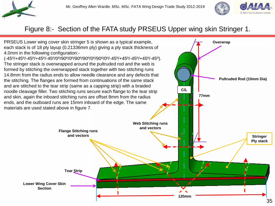
Figure 8:- Section of the FATA study PRSEUS Upper wing skin Stringer 1.
Pultruded Rod (10mm Dia)
Web Stitching runs
and vectors
Overwrap
C/L
77mm
120mm
Tear Strip
Flange Stitching runs
and vectors Stringer
Ply stack
Lower Wing Cover Skin
Section
PRSEUS Lower wing cover skin stringer 5 is shown as a typical example,
each stack is of 18 ply layup (0.21336mm ply) giving a ply stack thickness of
4.0mm in the following configuration:-
(-45º/+45º/-45º/+45º/-45º/0º/90º/0º/90º/90º/0º/90º/0º/-45º/+45º/-45º/+45º/-45º).
The stringer stack is overwrapped around the pultruded rod and the web is
formed by stitching the overwrapped stack together with two stitching runs
14.8mm from the radius ends to allow needle clearance and any defects that
the stitching. The flanges are formed from continuations of the same stack
and are stitched to the tear strip (same as a capping strip) with a braided
noodle cleavage filler. Two stitching runs secure each flange to the tear strip
and skin, again the inboard stitching runs are offset 8mm from the radius
ends, and the outboard runs are 15mm inboard of the edge. The same
materials are used stated above in figure 7.

Mr. Geoffrey Allen Wardle. MSc. MSc. FATA Wing Design Trade Study 2012-2019
36
Figure 9:- Section of the FATA Study PRSEUS Coaming Stringer.
Pultruded Rod (10mm Dia)
Lower Wing Cover Skin Section
126mm
Web Stitching runs
and vectors
Tear Strip
Flange Stitching runs
and vectors
120mm
Stringer
Ply stack
The PRSEUS Coaming Stringers have an 18 ply stack layup of 0.21336mm
ply giving a thickness of 4.0mm, in the following configuration:-
(-45º/+45º/-45º/+45º/-45º/0º/90º/0º/90º/90º/0º/90º/0º/-45º/+45º/-45º/+45º/-45º).
Flange Stitching runs are angled at 45º inboard, and normal to the flange
surface outboard. All other features and materials as other main stringers see
figure 8.
C/L
Overwrap

Mr. Geoffrey Allen Wardle. MSc. MSc. FATA Wing Design Trade Study 2012-2019
37
Figure 10:- RS 545 and RS 543 Lock stitching machines proposed for the FATA stringers.
Figure 10(a):- The RS 545 Lock stitching machine mounted on a KUKA
robot used in a KL 500 robot sewing workstation by Eurocopter to
stitch I – beam webs. Reference KSL Composites Europe 2014 VDMA
forum.
Figure 10(b):- Detailed view of the stitching head proposed
for the two rows of stitching on PRSEUS stringer webs.
Figure 10(d):- Detailed view of the stitching head proposed
for the two rows of stitching on PRSEUS stringer flanges. Figure 10(c):- The RS 545 Lock stitching machine mounted on a KUKA
robot used in a KL 500 robot sewing workstation by Eurocopter to
stitch I – beam flanges.
Mr. Geoffrey Allen Wardle. MSc. MSc. FATA Wing Design Trade Study 2012-2019
38
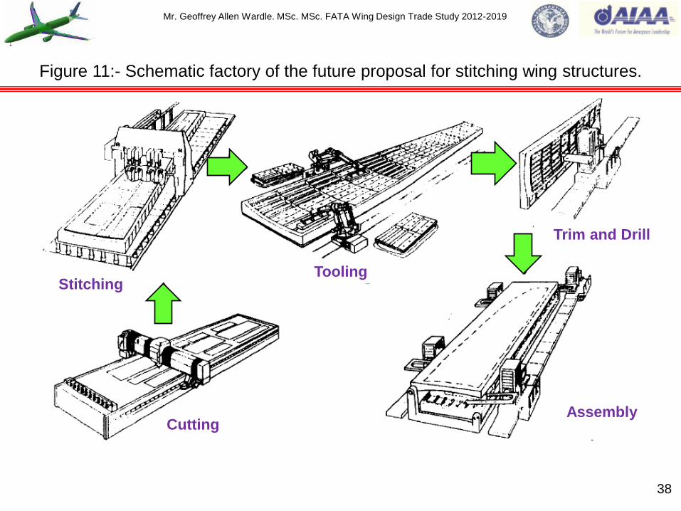
Figure 11:- Schematic factory of the future proposal for stitching wing structures.
Stitching
Cutting
Tooling
Assembly
Trim and Drill

Mr. Geoffrey Allen Wardle. MSc. MSc. FATA Wing Design Trade Study 2012-2019
Vacuum Assisted Resin Transfer Moulding:- The Vacuum Assisted RTM process is a single-
sided tooling process, and involves laying a dry fibre preform onto a mould, then placing a
permeable membrane on top of the preform, and finally vacuum bagging the assembly. Inlet and
exit feed tubes are positioned through the bag, and a vacuum is pulled at the exit to infuse the
preform. The resin will quickly flow trough the permeable material across the surface, resulting in a
combination of in-plane and through thickness flow and allowing rapid infusion times. The
permeable material is usually a large open area woven cloth or plastic grid. Commercial “shade-
cloth” is often used for this process. In foam cored sandwich structures, the resin can be
transported through grooves and holes machined in the core, eliminating the need for other
distribution media. The VARTM process results in lower fibre / volume fractions than RTM because
the preform is subjected to vacuum compaction only. However for the PRSEUS process this is
addressed by stitching the preform before layup as shown in figure 12(a), and in additional soft
tooling (bagging aides) are also used figure 12(b) and in the Boeing Controlled Atmospheric
Pressure Resin Infusion process figure 12(c), resin infusion takes place in a walk in oven at 60°C,
and following injection the assembly is then cured at 93°C for five hours, and then finally with the
vacuum bag removed post cured for two hours at 176°C with a final CNC machining to remove
excess material. The full process is documented in NASA/CR-2011-216880. The main advantages
of the CAPRI process over conventional VARTM is increased performance for airframe standard
parts, and over RTM reduced tooling costs and production of larger components, and over
conventional processing the elimination of a specialist autoclave. The full process and
manufacturability using this process will be a major focus of this project, and figures 13 and 14
show current PRSEUS structures and NASA‟s road map for development.
PRSEUS component post assembly processing overview.
39

Mr. Geoffrey Allen Wardle. MSc. MSc. FATA Wing Design Trade Study 2012-2019
40
Figure 12:- Boeing Controlled Atmospheric Pressure Resin Infusion (CAPRI) process.
Fig 12(b):- Soft tooling (bagging aids) installation over stiffeners.
Fig 12(a):- Robotic stitching of dry preform assembly.
Fig 12(c):- Vacuum bag installation over dry preform assembly.

Mr. Geoffrey Allen Wardle. MSc. MSc. FATA Wing Design Trade Study 2012-2019
41
Figure 13:- NASA‟s PRSEUS (CAPRI process) Development Roadmap.

Mr. Geoffrey Allen Wardle. MSc. MSc. FATA Wing Design Trade Study 2012-2019
42
Figure 14:- NASA / Boeing Block development of PRSEUS Structures to achieve TRL.
Mr. Geoffrey Allen Wardle. MSc. MSc. FATA Wing Design Trade Study 2012-2019
43
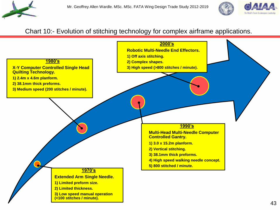
1970‟s
Extended Arm Single Needle.
1) Limited preform size.
2) Limited thickness.
3) Low speed manual operation (<100 stitches / minute).
1980‟s
X-Y Computer Controlled Single Head Quilting Technology.
1) 2.4m x 4.6m planform.
2) 38.1mm thick preforms.
3) Medium speed (200 stitches / minute).
1990‟s
Multi-Head Multi-Needle Computer Controlled Gantry.
1) 3.0 x 15.2m planform.
2) Vertical stitching.
3) 38.1mm thick preforms.
4) High speed walking needle concept.
5) 800 stitched / minute.
2000‟s
Robotic Multi-Needle End Effectors.
1) Off axis stitching.
2) Complex shapes.
3) High speed (>800 stitches / minute).
Chart 10:- Evolution of stitching technology for complex airframe applications.

Mr. Geoffrey Allen Wardle. MSc. MSc. FATA Wing Design Trade Study 2012-2019
Chart 11:- NASA / Boeing Building Block Methodology for PRSEUS Structures TRL.
44
Based on this Boeing Technology Readiness
Level (TRL) Diagram the PRSEUS structure
manufacturing technology is currently at TRL-
5 for primary structures and TRL-6/7 for
secondary structures see also figure 14.
NOTE:- PROSESSING AND PROCESS VARIABILITY CAN HAVE A SIGNIFICANT IMPACT ON
STRUCTURAL PERFORMANCE.

Mr. Geoffrey Allen Wardle. MSc. MSc. FATA Wing Design Trade Study 2012-2019
Overall loading on lifting surfaces:- Figure 15 illustrates the symmetrical flight case forces and
moments to be considered in wing structural design. The structural role of the wing includes the
following (ref 4):-
The transmission of lift the force, which is balanced at the root by the air loads on the fuselage
and the stabilizer and by the inertial loads:
The collection of the chord-wise air loads and the loads from control surfaces and high-lift device
hinges and the transfer of them to the main span-wise beam structure, which has to be achieved
by a series of chord-wise beams and gives rise to a torque on the span-wise structure as well as
contributing to the span-wise bending of the wing:
The transfer to the main beam of the local inertia loads from the wing mounted powerplants, and
retracted main landing gear units:
The reaction of landing loads from the main landing gear units:
The pressure and inertia loads from integral fuel tanks and fuel:
The provision of adequate torsional stiffness of the wing in order to satisfy the aeroelastic
requirements:
The reaction of wing and landing gear drag loads and possibly, thrust loads in the plane of the
wing.
Figures 16(a) through (c) illustrate Symmetric:- span-wise, chord-wise, and fuselage loading.
Figures 17(a) through (d) illustrate Asymmetric (roll):- span-wise, fuselage torque, and fuselage
sideslip and yaw loading, and figure 14(a) and (b) illustrates overall ground loading. Figure 15
illustrates overall fuselage loading 45
Section 4:- Overall loading on the aircraft primary structures.

Mr. Geoffrey Allen Wardle. MSc. MSc. FATA Wing Design Trade Study 2012-2019
46
Figure 15:- Overall loading on the aircraft wing surfaces.
Lw
Dw Lc
T
R
S
D
Wing inertias (structural / fuel) – relieve
all vertical and in-plane effects. Main landing gear.
R= Vertical – wing vertical shear, moment, torque.
D= Drag – wing in-plane shear, moment, torque.
S= Side – wing vertical moment.
Lw= Wing lift – wing vertical shear, moment, torque.
Lc= Control /high-lift devices – wing vertical shear, moment, torque.
Dw= Wing drag – wing in –plane shear, moment.
T = Thrust – wing in – plane shear, moment, torque.

Mr. Geoffrey Allen Wardle. MSc. MSc. FATA Wing Design Trade Study 2012-2019
Symmetric flight cases:- Figure 16(a) illustrates the loading and corresponding form of the shear
force diagram across the wing of a twin engined low wing commercial airliner configuration similar
to the baseline study aircraft. Symmetric wing lift is relieved by the inertia of the structure, engines,
systems and fuel (see section 6). The overall loading on the wing is reacted at the side of the
fuselage at the wing root joint, and the bending moment is constant across the fuselage.
The loads on a typical chord-wise wing section are illustrated in figure 16(b), the sum of the
moments of the forces about a given chord-wise reference point yields the torque at that section,
and the integration of the local values of the torque across the span of the wing yields the overall
torque diagram.
Finally figure 16(c) illustrates the loading and the basic form of the shear force diagram along the
length of the fuselage of a twin engined low wing commercial airliner similar to the baseline study
aircraft. The shear force and bending moment due to the horizontal air-load are relived along the
fuselage by the transitional and rotational inertia effects. The net fuselage bending moment at the
fore and aft centre of gravity (c.g.) position is balanced by the sum of the wing torques at the sides
of the fuselage.
Asymmetric flight case:- The asymmetric flight cases are more complex than the symmetric
cases. A simplified example is the instantaneous application of aileron control on a wing having no
initial lift results in an asymmetric loading case, although in practice there is no true symmetry
between the up-rising and down-lowering ailerons. A more usual case is when the ailerons are
applied as the aircraft is in steady level flight as shown in figure 13(a).
47
Overall loading on the aircraft primary structures (continued).

Mr. Geoffrey Allen Wardle. MSc. MSc. FATA Wing Design Trade Study 2012-2019
Figure 16(a):- Symmetric span – wise loading steady level flight condition.
48
Horizontal stabilizer load.
Span-wise airload. Net distributed span-wise load.
Fuselage reactions.
Powerplant inertia. Powerplant inertia.
Span-wise inertia load. Span-wise inertia load.
SHEAR FORCE DIAGRAM.

Mr. Geoffrey Allen Wardle. MSc. MSc. FATA Wing Design Trade Study 2012-2019
49
Powerplant weight.
Thrust -T
Aerodynamic moment - M
Control / Flap moment.
Aerodynamic Lift - L
Aerodynamic Drag - D
Control Force.
Control surface drag.
Wing structural systems
and fuel weight.
Figure 16(b):- Symmetric loading chord – wise torques on the aircraft wing.

Mr. Geoffrey Allen Wardle. MSc. MSc. FATA Wing Design Trade Study 2012-2019
50
Figure 16(c):- Symmetric flight case fuselage loading.
Thrust.
Drag.
Horizontal stabilizer airload.
Aerodynamic moment from wing.
Wing lift. Fuselage lift.
Centre of gravity.
Fuselage reaction.
Aircraft inertia.
Fuselage reaction
Stabilizer load
SHEAR FORCE DIAGRAM.

Mr. Geoffrey Allen Wardle. MSc. MSc. FATA Wing Design Trade Study 2012-2019
Asymmetric flight case (continued):- The initial steady level flight condition will have a symmetric
loading as shown in figure 16(a). The aileron and the consequent roll effects are approximately anti-
symmetric in form figure 17(a). Figure 17(b) shows the shear force distribution due to this anti-
symmetric condition as well as the overall result of combining it with the symmetric diagram. In a
general rolling motion the couple resulting from the application of the aileron is balanced both by
the acceleration effect of the roll inertia and the aerodynamic effect due to the rate of roll (ref:-4).
The torque loading on the rear fuselage as a consequence of the application of the rudder control to
cause a sideslip motion is shown in figure 17(c). The torque due to the fin side load is increased by
the effect of asymmetric distribution of the trimming load on the horizontal stabilizer.
Figure 17(d) shows the plan view of the fuselage, illustrating how the fin side load is reacted by side
forces along the fuselage. The lateral bending along the fuselage is relived by sideslip and yaw
inertial effects and the net value at the wing root is balanced by wing aerodynamic forces and yaw
inertia. The torque on the fuselage is mainly reacted by the rolling inertia of the wing group.
Fuselage cyclic pressure loading is also very important and is considered in fuselage loadings later
in this study.
Ground loading cases:- The ground loading cases unlike the flight cases occur from local ground
forces. The take - off case is effectively a static balance of the aircraft weight by the vertical loads
on the nose – and main – wheels. However, the landing cases are not static in that even after the
wheels have made contact with the ground there is a translational motion of the centre of gravity of
the aircraft, as well as a rotation in pitch and, possibly, roll. It is also usual for the wing to be
providing lift at the time of wheel contact with the runway. Figures 18(a) and (b) illustrate the nature
of the landing gear span-wise loading, and the longitudinal loading.
Overall loading on the aircraft primary structures (continued).
51

Mr. Geoffrey Allen Wardle. MSc. MSc. FATA Wing Design Trade Study 2012-2019
52
Figure 17(a):- Asymmetric (roll) span – wise loading flight condition.
Force due to aileron
application.
Net wing load in steady level flight.
Load due to rate of rotation in roll (roll damping).
Fuselage reactions – balance net
vertical force and rolling moment.
Resultant force and moment at fuselage Net moment is the difference of aileron, roll rate, and inertia effects.
Force due to aileron
application.

Mr. Geoffrey Allen Wardle. MSc. MSc. FATA Wing Design Trade Study 2012-2019
53
Figure 17(b):- Asymmetric (roll) span – wise loading flight condition shear force diagrams.
Aircraft C/L
Powerplant inertia. Anti-symmetric load.
Aircraft C/L
Fuselage reaction.
Overall.

Mr. Geoffrey Allen Wardle. MSc. MSc. FATA Wing Design Trade Study 2012-2019
54
Reacting fuselage side
load (balanced by inertia
and wing-body air-load.
Fin side load.
Asymmetrical trim load on horizontal tail.
Reacting fuselage torque (balanced
mainly by wing rolling inertia.
Aircraft C/L
Figure 17(c):- Asymmetric loading flight condition fuselage torque.

Mr. Geoffrey Allen Wardle. MSc. MSc. FATA Wing Design Trade Study 2012-2019
55
Figure 17(d):- Loading on the fuselage (sideslip, yaw and pressure).
Resultant side force – balanced by lateral (horizontal) inertia.
Fuselage side air-load (distributed along fuselage length.
Fin side load.
Moment at centre of gravity due to side loads –
balanced by yawing (rotational) inertia.
Cabin Pressurisation creates cyclic hoop tensile
stresses in the fuselage skin.
P
A
A
Section view on A

Mr. Geoffrey Allen Wardle. MSc. MSc. FATA Wing Design Trade Study 2012-2019
Ground loading cases (continued):- The various forces and moments are balanced in the same
way as those arising in the flight cases, that is primarily by inertial effects. For this reason here the
ground contact forces are regarded as applied loads rather than as reacting forces.
Overall loading on the fuselage:- The loading determining the design of the fuselage is shown in
figure 19. The roles of the fuselage includes the following:-
Provision of a pressurized (in commercial aircraft) envelope and structural support for the
payload (passengers and freight) and crew. The skin thickness required to limit hoop tensile
stresses to acceptable values is given by:- tp = ∆ρR / σρ Where:- ∆ρ is the maximum working differential
pressure: R is the local radius of the shell : and σρ is the allowable tensile working stress.
To react landing gear, pressurization (in commercial aircraft), and powerplant loads when these
items are located on, or within the fuselage, the nose gear being always present.
To transmit the control and trimming loads from the stabilizing / control surfaces to the centre of
the aircraft, and to provide support and volume for equipment and systems.
These requirements imply that to perform its structural role the fuselage has to be a longitudinal
beam loaded both vertically and laterally, it also has to react torsion and local concentrated loads,
the provision of a pressurized envelope implies a cylindrical encapsulated construction, with
pressure bulkheads. Therefore a conventional commercial airliner fuselage of circular cross section,
cabin floor, and cargo bay floor, with pressurized cabin, and external powerplants is the baseline
FATA airframe.
56
Overall loading on the aircraft primary structures (continued).

Mr. Geoffrey Allen Wardle. MSc. MSc. FATA Wing Design Trade Study 2012-2019
57
Figure 18(a):- Ground loading span – wise.
S
Ground vertical loads = R R R
Ground side loads = S
Resultant force and moment at fuselage.
Net wing load.
Fuselage reaction to balance vertical and side loads and rolling moment
due to side load – balanced by roll, vertical and horizontal inertias.

Mr. Geoffrey Allen Wardle. MSc. MSc. FATA Wing Design Trade Study 2012-2019
58
Ground vertical loads = R R
D Ground drag loads = D
Fuselage vertical force – reacted
by vertical (translational) inertia.
Fuselage bending moment – reacted
by pitch (rotational) inertia.
Overall lift and weight in balance.
Figure 18(b):- Ground loading longitudinal.
Mr. Geoffrey Allen Wardle. MSc. MSc. FATA Wing Design Trade Study 2012-2019
59
Figure 19:- Overall loading on the fuselage.
LF
LT
D
R
S
D
R
S
Main landing gear.
Nose landing gear.
LF = Fin load – fuselage horizontal shear, moment, torque:
LT = Tail load – fuselage vertical shear, moment, torque.
R = Vertical - fuselage vertical shear moment:
D = Drag – fuselage vertical shear moment:
S = Side – fuselage horizontal shear, moment, torque.
Cabin Pressurisation creates cyclic hoop tensile stresses in the fuselage skin.
P

Mr. Geoffrey Allen Wardle. MSc. MSc. FATA Wing Design Trade Study 2012-2019
Aircraft structures fall into 3 categories which are as follows:-
Class 1:- structural component the failure of which will result in structural collapse; loss of control;
failure of motive power, injury or fatality (to any occupant); loss of safe operation of the aircraft.
Class 2:- Stresses components but not Class1.
Class 3:- Unstressed or lightly stresses component which is neither Class 1 or 2.
Structural integrity is defined as the capability of the structure to exceed applied design loading
throughout its operational life, and the selection of a design philosophy to achieve this from the start
of the design process is extremely important as this selection impacts on:- airframe weight;
maintainability; service life; and any future role change of the airframe. The approaches available to
the designer are:- Static Strength; Safe Life; Failsafe; Damage Tolerance; and Fatigue Life, the last
four of which, are expanded below (ref:-4). See tables 3 through 5 for FATA candidate materials
selection.
(a) Safe Life:- The important criterion in this approach is the time before a „crack or flaw‟ is initiated
and the subsequent time before it grows to critical length. It can be seen from a typical S-N
curve that low levels of stress at high frequency of application theoretically do not cause any
fatigue damage. However it is necessary to allow for them, possibly by introducing a stress
factor such that effectively damage dose not occur.
(b) Fail-safe:- In this approach the dominate factors are the crack growth rate and the provision of
structural redundancy in conjunction with appropriate structural inspection provision.
60
Section 5:- Structural design philosophy of airframe structural components.

Mr. Geoffrey Allen Wardle. MSc. MSc. FATA Wing Design Trade Study 2012-2019
There are several ways of ensuring that fail safety is achieved:-
i. By introducing secondary, stand-by components which only function is in the event of a
failure of the primary load path, to carry the load. This may consist of a tongue or a stop
which is normally just clear of the mating component. A mass penalty may be implied but in
same circumstances it is possible to use the secondary items in another role, for example
the need for a double pane assembly on cabin windows for thermal insulation purposes.
ii. By dividing a given load path into a number of separate members so that in the event of the
failure of one of them the rest can react the applied load. An example of this is the use of
several span wise planks in the tension surface of metallic wing boxes. When the load path
is designed to take advantage of the material strength the use of three separate items
enables any two remaining after one has failed to carry the full limit load under ultimate
stress. In some instances the „get home‟ consideration may enable a less severe approach
to be adopted.
iii. By design for slow crack growth such that in the event of crack initiation there is no danger
of a catastrophic failure before it is detected and repaired.
c) Damage tolerant:- With this philosophy it becomes necessary to distinguish between
components that can be inspected and those that cannot. Effectively either the fail-safe or
safe-life approaches are then applied, respectively, in conjunction with design for slow crack
growth and crack stopping (e.g. panel braking web stiffeners).
61
Structural design philosophy of airframe structural components.
Mr. Geoffrey Allen Wardle. MSc. MSc. FATA Wing Design Trade Study 2012-2019
A. Safe-life and Fail–safe design processes (see Chart 11):- There is a commonality in the design
process for the safe –life and fail-safe concepts. The material to be used for the structure must
be selected with consideration of the critical requirements for crack initiation or crack growth
rate, as most relevant, together with the operating environment. A vital consideration for fail-
safe design is the provision of the alternative load paths, possibly together with crack
containment or crack arresting features. When these decisions have been made it is possible to
complete the design of the individual components of the structure and to define the
environmental protection necessary.
In the case of the safe-life concept the life inclusive of appropriate life factor follows directly
from the time taken initiation of the first crack to failure. Inspection is needed to monitor crack
growth. In the fail-safe concept the life is determined by the structure possessing adequate
residual strength subsequent to the development and growth of cracks.
In both cases it essential to demonstrate by testing, where possible on a complete specimen of
the airframe, that the design assumptions and calculations are justified. Further, in fail-safe
design it is necessary to inspect the structure at regular, appropriate intervals to ensure that any
developing cracks do not reach the critical length and are repaired before they do so.
As the design process is critically dependent upon assumed fatigue loading it is desirable, if not
essential, to carry out load monitoring throughout the operational life of the airframe. This is
used either to confirm the predicted life, or where necessary, to modify the allowable
operational life.
62
Structural design philosophy application processes.

Mr. Geoffrey Allen Wardle. MSc. MSc. FATA Wing Design Trade Study 2012-2019
63
Safe-Life.
Crack Initiation time.
Fail-Safe.
Crack growth rate.
Provision of redundancies.
Crack containment.
Environment.
Material: Component Design:
Corrosion protection: Testing.
Life. Residual strength.
In service load monitoring.
Chart 11:- Application of Safe-life and Fail-safe structural design philosophies.
Mr. Geoffrey Allen Wardle. MSc. MSc. FATA Wing Design Trade Study 2012-2019
B. Damage Tolerant Design process (see Chart 12):- The damage tolerant approach commences
with the assumption that cracks or faults are present in the airframe as manufactured.
Experience suggests that these vary in length from 0.1mm to as much as 1.5mm.
Those items of the structure which may be readily inspected can be designed by selecting an
appropriate material and then applying essentially a fail-safe approach. The working stress
level must be selected and used in conjunction with crack stopping features to ensure that any
developing cracks grow slowly. Inspection periods must be established to give several
opportunities for a crack to be discovered before it attains a critical length.
When it is not possible to inspect a particular component it is essential to design for slow–crack
growth and ensure that the time for the initial length to reach its critical failure value is greater
than the required life of the whole structure. Since this approach is less satisfactory than that
applied to parts that can be inspected it is desirable to develop the design of the airframe such
that inspection is possible, wherever this can be arranged. As with safe-life and fail-safe
philosophies testing is needed to give confidence in the design calculations. Likewise, in-service
load monitoring is highly desirable for the same reason. This design philosophy is employed on
this project using techniques from ref:-4, JAR 25, and data sheets, MSc F&DT module notes.
C. Fatigue-life Design process (see Chart 13):- The first stage in the fatigue-life approach is the
definition of the relevant fatigue loads and the determination of the response of the aircraft
structure to these loads. The analysis for this follows that for limit load conditions, which
enables the loading on individual components of the airframe to be determined, and the
airframe structural response to be assed and the best design philosophy to be applied. 64
Structural design philosophy application processes.

Mr. Geoffrey Allen Wardle. MSc. MSc. FATA Wing Design Trade Study 2012-2019
Chart 12:- Application of the Damage Tolerance structural design philosophy.
Damage Tolerant.
Crack in structure as manufactured.
Is the component inspectable?
Yes. No.
Fail-safe approach.
Slow crack growth.
Crack arrest features.
Inspection periods.
Crack growth to initiate
failure to be more than
service life.
Testing.
In service load monitoring (FTI / G monitors / SHM). 65

Mr. Geoffrey Allen Wardle. MSc. MSc. FATA Wing Design Trade Study 2012-2019
66
Chart 13:- Application of the Fatigue-life structural design philosophy.
Fatigue-life.
Aircraft structural response.
Fatigue load spectra.
Design philosophy selection.
Damage Tolerant. Safe-Life. Fail-Safe.
Mr. Geoffrey Allen Wardle. MSc. MSc. FATA Wing Design Trade Study 2012-2019
Fatigue Design Requirements:- The emphasis of the requirements specified to ensure the integrity
of the airframe design under fatigue loading is on the methods of analysis and the means of
determination of a satisfactory fatigue life. Only in the United States military code is there a
specification of a magnitude and frequency of repeated loading and this is outlined below. Loading
conditions for all categories of aircraft are discussed below.
1) Civil transport aircraft JAR 25.571:- This standard outlines the basic requirements for fatigue
evaluation and damage tolerance design of transport aircraft. The paragraph outlines the
general requirements for the analysis and the extent of the calculations. Amplification of the
details is given in the associated „acceptable methods of compliance‟ given in JAR 25.ACJ
25.571.
2) UK Military Aircraft:- The basic requirements for fatigue analysis and life evaluation are
specified in Def Stan 00970 Chapter 201. This covers techniques for allowing for variances in
the data as well as overall requirements and the philosophy to be adopted. Detail requirements
of the frequency and magnitude of the repeated loading are given in the particular specification
for the aircraft.
3) US Military Aircraft:- The United States military aircraft stipulations are to be found in three
separate documents:- In MIL-A-8866A the emphasis is on the detail of the required magnitude
and frequency of the repeated loading rather than on analysis the data covers;- maneuver;
gust; ground and pressurization conditions for fighter, attack, trainer, bomber, patrol, utility and
transport aircraft. 67
Structural design fatigue requirements for design philosophy application.

Mr. Geoffrey Allen Wardle. MSc. MSc. FATA Wing Design Trade Study 2012-2019
MIL-A-8867 prescribes the ground testing to be undertaken as part of the demonstration of the
life of the airframe. The final document the is MIL-8868 paragraph 3.4 and 3.5 which stipulate
the information to be provided in the form of reports outlining the analysis and testing
undertaken to substantiate the life of the airframe.
The types of repeated airframe load data required for design against fatigue and to apply in the
selected component design philosophy are outlined below.
1) Symmetric manoeuvre case:- Extensive information is available in relation to symmetric
manoeuvres of both military and civil aircraft, e.g. Van Dijk and Jonge‟s work which outlines a
fatigue spectrum obtained from flying experience of fighter / attack aircraft which is known as
the FALSTAFF spectrum, based on the maximum value of peak stress (s) and loading
frequency (n) the peak stress selected being the Input Parameter.
2) Asymmetric manoeuvre case:- Fatigue loading data for asymmetric manoeuvre loading is
sparse, and these originate from the roll and yaw controls, the texts of Taylor derives data from
early jet fighter experience. As for civil aircraft it has been determined that atmospheric
turbulence is of much greater significance.
3) Atmospheric turbulence:- Fatigue loading due to encounters with discrete gusting or the effect
of continuous turbulence is of importance for all classes of aircraft, but especially for those
where operational role does not demand substantial manoeuvring in flight. ESDU data sheets
69023 (Average gust frequency for Subsonic Transport Aircraft (ESDU International plc. May
1989) is used in this study.
68
Structural design fatigue requirements for design philosophy application.

Mr. Geoffrey Allen Wardle. MSc. MSc. FATA Wing Design Trade Study 2012-2019
There are two main types of turbulence which are:- (a)Symmetric Vertical Turbulence, and
(b)Lateral Turbulence.
a) Symmetric Vertical Turbulence:- where gust magnitude is a function of both flight altitude and
terrain over which the aircraft is flying, e.g. low level penetration bombing missions B-1B,
Tornado, and B-52H, where there are more up gusts than down, these are allowed for by
using correction factors.
b) Lateral Turbulence:- there is less information on the frequency and magnitude of lateral
turbulence for aircraft but it has been suggested that at altitudes below about 3km the
frequency of a given magnitude is some 10-15% greater than those of the corresponding
vertical condition.
4) Landing gear loads:- these fall into three categories;- (a) loads due to ground manoeuvring e.g.
taxiing; (b) the effects of the unevenness of the ground surface e.g. unpaved runways, rough
field poor condition runways, major consideration in troop / cargo military transports, and
forward based CAS aircraft; (c) landing impact conditions. The texts of Howe (ref:-4): Niu: and
MIL-A-8866A are employed in this project.
5) Buffeting Turbulence:- Flow over the aircraft may break down at local points and give rise to
buffeting. This induces a relatively high – frequency variation in the aerodynamic loads,
possibly resulting in the fatigue of local airframe components such as metallic skin panels.
6) Acoustic Noise Turbulence:- local high frequency vibration or flow field loading, and ESDU Data
sheets 75021 and 89041 were used in this project.
69
Structural design fatigue requirements for design philosophy application.

Mr. Geoffrey Allen Wardle. MSc. MSc. FATA Wing Design Trade Study 2012-2019
Materials Code ρ
Kg/m
E
GPa
σe
MPa kht khc kdt kdc kθ
Carbon /
Epoxy. 3501/6 QI 1605.44 67 736 0.61 0.65 0.55 0.38 0.83
Carbon /
Epoxy. 3501/6 O 1605.44 80 880 0.55 0.62 0.55 0.38 0.83
Ti Alloy Ti6Al4V 4428.8 110 902 0.94 0.94 0.20 0.94 1.00
Al/Li Alloy 8090 T3X 2530 80 329 0.94 0.94 0.39 0.94 0.90
Al Alloy 7075 T76 2768 72 483 0.94 0.94 0.29 0.94 0.90
Al Alloy 2024 T351 2768 72 325 0.94 0.94 0.31 0.94 0.90
70
3
Table 3(a):- Materials Properties of FATA wing / empennage materials (Ref.6).

Mr. Geoffrey Allen Wardle. MSc. MSc. FATA Wing Design Trade Study 2012-2019
Table 3(b):- Materials Properties for FATA fuselage materials (Ref.22).
Property. Unidirectional Tape /Slit Tape. Plain Weave Fabric.
Thickness per ply 0.15mm 0.25mm
Density (ρ) 1790kg/m 1570kg/m
Longitudinal modulus E1 (GPa) 137.3 62.6
Transverse modulus E2 (GPa) 7.8 59.3
In-plain Shear modulus G12 (GPa) 5.23 4.6
Poisson's ratio V12 0.36 0.062
Longitudinal tensile strength F1t (MPa) 2057 621
Transverse tensile strength F2t (MPa) 46.9 594
Longitudinal compressive strength F1c (MPa) 1610 760
Transference compressive strength F2c (MPa) 207 707
In-plain shear strength F6 (MPa) 135 125
Standard Width ATL* 460mm / AFP* 12.5mm 1600 mm
71 *ATL= Automated Tape Laying : AFP = Automated Fibre Placement.
3 3

Mr. Geoffrey Allen Wardle. MSc. MSc. FATA Wing Design Trade Study 2012-2019
Category. Failure Mode. Weight Ratio (W2 / W1)
1 Tensile strength. ρ2 / ρ1 σe1/σe2 [kth1/ kth2 kθ1/kθ2]
2 Compressive strength. ρ2 /ρ1 σe1/σe2 [kch1/kch2 kθ1/kθ2]
3 Crippling ρ2 / ρ1 [Es1 σe1 / Es2 σe2]
4 Compression surface column and crippling ρ2/ρ1 [Es1 Et1 σe1/Es2 Et2 σe2]
5 Buckling compression and shear ρ2 /ρ1 [E1 / E2]
6 Aeroelastic stiffness ρ2/ρ1 E1/E2
7 Durability and damage tolerance ρ2/ρ1 [kd1kθ1/kd2kθ2]
72
Table 4:- Weight Ratio Equations for Various Failure Categories (based on Ref.6).
0.25
0.2
1/3

Mr. Geoffrey Allen Wardle. MSc. MSc. FATA Wing Design Trade Study 2012-2019
Material Code
Weight Ratio (S1/S2) (ρ2/ρ1)
Cat 1 Cat 2 Cat 3 Cat 5 Cat 6 Cat 7(a) Cat 7(b)
Carbon /
epoxy 3501/6QI 0.4 0.4 0.5 0.4 0.6 0.2 0.7
Carbon /
epoxy 3501/6O 0.4 0.3 0.4 0.4 0.5 0.1 0.6
Titanium Ti6Al4V 0.5 0.5 1.1 1.0 1.0 0.8 0.5
Aluminium /
Lithium 8090T3X 0.9 0.9 0.9 0.9 0.8 0.7 0.9
Aluminium
alloy 7075 T76 0.7 0.7 0.9 0.9 1.0 0.7 0.7
Aluminium
alloy 2024 T3 1.0 1.0 1.0 1.0 1.0 1.0 1.0
73
Table 5:- Weight Ratios for Airframe Materials for Various Failure Categories (Ref.6).
n

Mr. Geoffrey Allen Wardle. MSc. MSc. FATA Wing Design Trade Study 2012-2019
74
The structural layout of the reference wing, and evolved wing based on the following fundamentals,
the wing has structurally to be both a span-wise and chord-wise beam and posses adequate
torsional stiffness and therefore be able to react the loads outlined in the previous slides. Figure 20
illustrates the control surfaces on the wing of the FATA subsonic composite transport aircraft, and
shows how the numerous leading and trailing edge devices occupy a significant portion of the
chord. The consequence of this is that only approximately half of the chord is available for the span-
wise beam of the torsion box, however it is the deepest portion and this is preferable for both
bending and torsion.
The primary load direction is well defined and is span-wise and therefore wings are good
candidates for the application of carbon – fibre composites providing the overall size is such that it
can be built with the minimum number of joints.
The primary wing box components of the baseline wing as is common with large transport aircraft
are:- the wing skin covers which form the lifting surface and transmit wing bending and torsion
loads, and these are stabilized with span-wise stringers to inhibit cover skin buckling, the stringers
reduce cover skin thickness requirements and hence cover weight as outlined below, (either CFC or
metallics are used for cover skins e.g. A380 uses 7449 and 7055 Al upper skins and 2024 and 2026
Al lower skins): the front and rear spars which in conjunction with the stringer stiffened skin transmit
bending and torsion loads, and consist of a web to react vertical shear loads, and edge flanges to
react the wing bending loads (and can be CFC or metallic e.g. A380 uses 7085 and 7040 Al for
spars: and ribs which maintain the aerodynamic shape of the wing cross-section, and structurally
transmit local loads chord-wise across to the span-wise torsion box, the ribs stabilize the spars and
skins in span-wise bending. In this study CFC cover skins / spars / and some ribs is the baseline.
Section 6:- Roll and layout of large aircraft wing structural members.

Mr. Geoffrey Allen Wardle. MSc. MSc. FATA Wing Design Trade Study 2012-2019
75
Figure 20:- Control surface layout of the FATA composite transport aircraft.
Six Outboard Leading edge slats.
Droop nose Leading edge slat.
Two Inboard
Spoilers with
droop function.
Five Inboard
Spoilers with
droop function.
Outboard Flap
single pivot.
Inboard Flap
single pivot.
All Speed Aileron.
Low Speed Aileron.
Rudder.
(Planform area 15m²)
Port Elevator
(Planform area 10 .18m²)
Stbd Elevator.
(Planform area 10.18m²)

Mr. Geoffrey Allen Wardle. MSc. MSc. FATA Wing Design Trade Study 2012-2019
76
COVER SKINS: - The covers form the lifting surface of the wing box and are subjected to span-
wise bending flight loads, the upper wing cover is subjected to primary compression loads, and
lower wing cover is subjected to primary tension loads. The upper wing covers are also subjected to
aerodynamic suction and fuel tank pressures, and both covers are subjected to chord-wise shear
due to the aerodynamic moment on the wing torsion box. Composite wing cover skins shown in
figure 21 can be aeroelastically tailored using: - 0º plies to react span-wise bending: 45º and -45º
plies to react chord-wise shear: and 90º plies to react aerodynamic suction and internal fuel tank
pressures, theses cover skins are monolithic structures and not cored. Combined with co-bonded
stringers, this produces much stronger yet lighter covers which are not susceptible to corrosion and
fatigue like metallic skins. The production method of these cover skins is by Fiber Placement:-
which is a hybrid of filament winding and automated tape laying, the machine configuration is
similar to filament winding and the material form is similar to tape laying, this computer controlled
process uses a prepreg Tow or Slit material form to layup non-geodesic shapes e.g. convex and
concave surfaces, and enables in-place compaction of laminate, however maximum cut angle and
minimum tape width and minimum tape length impact on design process. The wing cover skin
weight in large transports, can be reduced by applying different ply transition solutions to the drop
off zones as shown in figure 22(a) and (b), maintaining the design standard 1:20 ramps in the
direction of principal stress (span-wise), and using 1:10 ramps in the transverse (chord-wise)
direction, as shown for the FATA wing covers, this requires stress approval based on analysis.
Because the wing chord depth of the transport aircraft considered exceeds 11.8” to reduce
monolithic cover skin weight and inhibit buckling co-bonded CFRP stiffeners are used as detailed
below and shown in figures 23, 24, and 25.
Roll and layout of large aircraft wing structural members ( CFC cover skins).

Mr. Geoffrey Allen Wardle. MSc. MSc. FATA Wing Design Trade Study 2012-2019
Figure 21(a):- Fibre Orientation Requirements for CFC Wing Skins / covers.
Tension Bottom Wing Cover Skin.
Compression Top Wing Cover Skin.
0º Plies are to react the wings spanwise bending.
The 4 Primary Ply Orientations Used for Wing Skin Structural Plies.
77
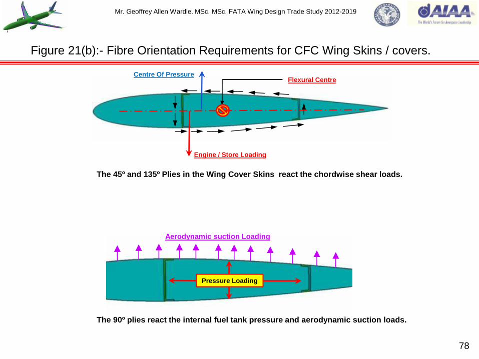
Mr. Geoffrey Allen Wardle. MSc. MSc. FATA Wing Design Trade Study 2012-2019
Figure 21(b):- Fibre Orientation Requirements for CFC Wing Skins / covers.
78
Centre Of Pressure
Engine / Store Loading
Flexural Centre
The 90º plies react the internal fuel tank pressure and aerodynamic suction loads.
The 45º and 135º Plies in the Wing Cover Skins react the chordwise shear loads.
Pressure Loading
Aerodynamic suction Loading

Mr. Geoffrey Allen Wardle. MSc. MSc. FATA Wing Design Trade Study 2012-2019
Fig 22(a):- FATA Structural Ply Thickness Zones Upper Wing Cover Skin R.6.1
79
PLY LEGEND.
This Legend gives the thickness
of plies in each orientation.
“t”
0º
90º
45º
135º
FWD
IN BD
24.0
6.0
3.0
7.5
7.5
24 mm
20.0
4.0
3.0
6.5
6.5
16.0
4.0
3.0
4.5
4.5
16 mm
12.0
3.0
2.0
3.5
3.5
12 mm
10.0
3.0
2.0
2.5
2.5
10 mm
8.0
3.0
1.0
2.0
2.0
8 mm
6.0
2.0
1.0
1.5
1.5
6 mm
20 mm
PLY DROP OFFS: - 1:20 SPANWISE / 1:10 CHORDWISE.
(For FATA study un-symmetrical ply drop off e.g. 1:20 in direction
of principal stress and 1:10 in the transverse direction for weight
reduction).
Outer OML Skin Ply.
See also figure 28 for lightening strike
protection and figures 29 and 30 for BVID
protection.
6.0
2.0
1.0
1.5
1.5
6 mm

Mr. Geoffrey Allen Wardle. MSc. MSc. FATA Wing Design Trade Study 2012-2019
Fig 22(b):- FATA Structural Ply Thickness Zones Lower Wing Cover Skin R.6.1
80
PLY DROP OFFS: - 1:20 SPANWISE / 1:10 CHORDWISE.
(For FATA study un-symmetrical ply drop off e.g. 1:20 in direction
of principal stress and 1:10 in the transverse direction for weight
reduction).
15 mm
10 mm
10 mm
20 mm
20 mm
15 mm
10 mm
6 mm
6 mm
8 mm
6 mm
6.0
2.0
1.0
1.5
1.5
6.0
2.0
1.0
1.5
1.5
“t”
0º
90º
45º
135º
PLY LEGEND.
8.0
4.0
1.0
1.5
1.5
6.0
2.0
1.0
1.5
1.5
10.0
3.0
2.0
2.5
2.5
10.0
3.0
2.0
2.5
2.5
10.0
3.0
2.0
2.5
2.5
15.0
4.0
2.0
4.5
4.5
15.0
4.0
2.0
4.5
4.5
20.0
4.0
3.0
6.5
6.5
20.0
4.0
3.0
6.5
6.5
This Legend gives the thickness
of plies in each orientation.
FWD
OUT BD
Outer OML Skin Ply.
10 mm
10.0
3.0
2.0
2.5
2.5

Mr. Geoffrey Allen Wardle. MSc. MSc. FATA Wing Design Trade Study 2012-2019
81
Fig 23:- FATA Transport aircraft upper cover skin stringer layout to inhibited skin buckling.
Fig 23(b) Upper Cover Skin Stringer Close up of area „A‟.
Fig 23(a) FATA Upper Cover Skin Stringer layout.
„A‟
As a Rule of Thumb:- The mass of the skins / covers is in the order of
twice that of the sub-structure. Therefore for transports and bombers
with deep wing cross-sections, stiffeners are used bonded to the
internal skin surface as shown in fig 23(a) for the FATA wing skins.
Where the wing chord thickness is much greater than 11.8 inches.
Figure 23(b) shows a close up of the stringers which are co-bonded „I‟
section and are of constant web depth through thickness zones with
ramped upper flanges. For the RRSEUS Stringer configuration a
variable web depth will be used over the zones.
Constant web height I - section stringers better in
compression (Tear strip peel plies omitted for clarity).
1:20 Skin Zone Transition
Ramps in the direction of
principle stress.

Mr. Geoffrey Allen Wardle. MSc. MSc. FATA Wing Design Trade Study 2012-2019
Composite cover skin stringer types: -
“L” Section Stiffeners:- are typically used as “panel barkers” and are usually mechanically
attached to skin panels. “L” stiffeners are fabricated on IML tooling with a semi-rigid caul
sheet, often fiberglass, on the OML surface to produce a smooth finish and reduce radius thin
out.
“Z” Section Stiffeners:- are usually mechanically attached to the skin panel and are typically
used to provide additional stiffness for out-of-plane loading. “Z” sections may be fabricated
by the RTM or hand-laid methods.
“I” Section Stiffeners:- are typically used as axial load carrying members on a panel
subjected to compression loading. “I” sections are fabricated by laying up two channel
sections onto mandrels and placing them back-to-back. A minimum of two tooling holes (one
at each end) is typically required to align the mandrels. Two radius fillers (“noodles” or
“cleavage filler”) are placed in the triangular voids between the back-to-back channels. On
one of the two flat sections of the stiffener a “capping strip” is used to tie the two flanges
together. The flanges on the cap side should have a draft (91º ± 1º) to ease mandrel removal
post cure. All “I”- beam flanges should have sufficient width to allow mechanical attached
repair.
“T” Section Stiffeners:- are a simplified version of the “I” section stiffener. “T” sections may
be used as either axial load carrying members or as panel breakers. “T” sections stiffeners
may be used as a lower cost alternative to “I” sections if the panel is designed as a tension
field application and the magnitude of reverse (compression) load is relatively small.
82
Roll and layout of large aircraft wing structural members (CFC cover skins).

Mr. Geoffrey Allen Wardle. MSc. MSc. FATA Wing Design Trade Study 2012-2019
83
Figure 24:- Composite stringer selection based on design experience.
“I” Section Stringer (used as axial load carrying
members on panel under compression loading).
Channel
sections Capping
strips
Cleavage
fillers
“T” Section Stringer (used as axial load carrying
members on panel under tension loading).
Capping strip
Cleavage filler
Channel
sections
“Z” Section Stringer (mechanically attached to
provide additional stiffness for out of plane
loading).
“L” Section Stringer (bonded or
mechanically attached panel breaker).
Mr. Geoffrey Allen Wardle. MSc. MSc. FATA Wing Design Trade Study 2012-2019
Composite wing cover skin stringer radius fillers (noodles):-
Radius fillers are necessary in T - and I – type composite stiffeners and spars. See figure 24
(previous slide) for a 2-D depiction of radius / cleavage fillers. There are several types of filler
material that have been used in previous design studies including:- rolled unidirectional prepreg (of
the same fiber / resin as the structure); adhesives; 3-D woven preforms; groups of individual tows
placed in the volume; and cut quasi-isotropic laminate sections. Experimentation has shown the
how effective these have been and a brief summary is as follows:-
Resin / adhesive noodles – Poor
Tow noodles – Fair
Braided noodle – Good
Braided “T” preform - Good to Excellent.
If rolled prepreg is used, ensure that the volume of the material to be rolled is a close match with
the cavity to be filled and consider using a forming tool to shape the noodle to near final
configuration. Also, it has been found that using a layer of softening adhesive rolled with the noodle
prepreg material will help alleviate cracking due to thermal mismatch between the noodle and the
surrounding material.
The capping strips are bonded in place using BSL322, supported film adhesive to give
constant/minimum glue line thickness of 0.005” per ply, 2 plies max typically. Figure 25 and 26
show how peel stresses and manufacturing weight can be reduced in stringer design. Figures 27(a)
and (b) shows the FATA lower cover skin stringer arrangement and special considerations for the
inspection cut outs, either side of which coaming stringers are installed.
Roll and layout of large aircraft wing structural members (CFC cover skins).
84

Mr. Geoffrey Allen Wardle. MSc. MSc. FATA Wing Design Trade Study 2012-2019
85
Figure 25:- Composite Stringer design based on design / test experience.
Distribution of peel stress in a basic co-bonded stringer subjected
to vertical load validated through „T‟- Pull testing, which can be
modified through redesigning the flange toe as shown.
8.5 N/mm²
Square Edge flange toe.
Radius Edge flange toe.
7.5 N/mm²
30º Chamfer flange toe
(selected for Prime
baseline FATA).
5 N/mm²
4 N/mm²
6º Chamfer flange toe strip
(selected for Developed
PRSEUS FATA). 1 N/mm²
6º Chamfer flange toe and capping.
TRADE STUDY.
REDUCTION OF PEEL STRESS
AT TOE OF FLANGE.
REDUCTION IN STRINGER
MASS.
INCREASED MANUFACTURING
COSTS.
ISSUES WITH REPAIR /
FASTENERS.

Mr. Geoffrey Allen Wardle. MSc. MSc. FATA Wing Design Trade Study 2012-2019
Fig 26(a)/(b):- Support of Joggles in CFC spars in structural assemblies.
Joggle is supported by a GRP tapered packer.
SHIM Packer
a) TYPICAL BONDED
ASSEMBLY Anti – peel fasteners
Utilize the ability to taper the feet of adjoining members this simplifies the
geometry of the joggle example CFC stringers and CFC ribs.
b) TYPICALASSEMBLY OF
PRE-CURED DETAILS
86

Mr. Geoffrey Allen Wardle. MSc. MSc. FATA Wing Design Trade Study 2012-2019
Co-Curing:- This is generally considered to be the primary joining method for joining
composite components the joint is achieved by the fusion of the resin system where two (or
more) uncured parts are joined together during an autoclave cure cycle. This method minimises
the risk of bondline contamination generally attributed to post curing operations and poor
surface preparation. But can require complex internal conformal tooling for component support.
Co-Bonding:- The joint is achieved by curing an adhesive layer added between a co-cured
laminate and one or more un-cured details. This also requires conformal tooling and as with co-
curing the bond is formed during the autoclave cycle, this method was used on Eurofighter
Typhoon wing spars which were co-bonded to the lower wing cover skins, and proposed for the
F-35B VT lower skin stringers in SWAT trade studies, and is used to bond the wing cover skin
stringers for large transport aircraft see section 7. Care must taken to ensure the cleanliness of
the pre-cured laminate during assembly prior to the bonding process.
Secondary Bonding:- This process involves the joining of two or more pre-cured detail
parts to form an assembly. The process is dependent upon the cleaning of the mating faces
(which will have undergone NDT inspection and machining operations). The variability of a
secondary bonded joint is further compounded where „two part mix paste adhesives‟ are
employed. Generally speaking, this is not a recommended process for use primary structural
applications.
Design options for stringer adhesive bonded joints detailed in WB1.
87

Mr. Geoffrey Allen Wardle. MSc. MSc. FATA Wing Design Trade Study 2012-2019
Fig 27(a):- FATA lower cover skin with co – bonded coaming stringer layout and ports.
Lower cover skin access cut-outs ports require local coaming stringers
on each side to compensate for the reduced stringer number, these have
a higher moment of inertia and smaller cross sectional area to absorb
local axial loads due to the ports.
The stringers next to the local coaming stringers on each
side need to have larger cross sectional areas to absorb a
portion of the coaming stringer load.
Stringers on the lower wing skin cover are of T- section
which are better panels under tension loading. (Tear –
strip peel plies omitted for clarity).
1:20 Skin Zone
Transition Ramps
in the direction of
principle stress.
88
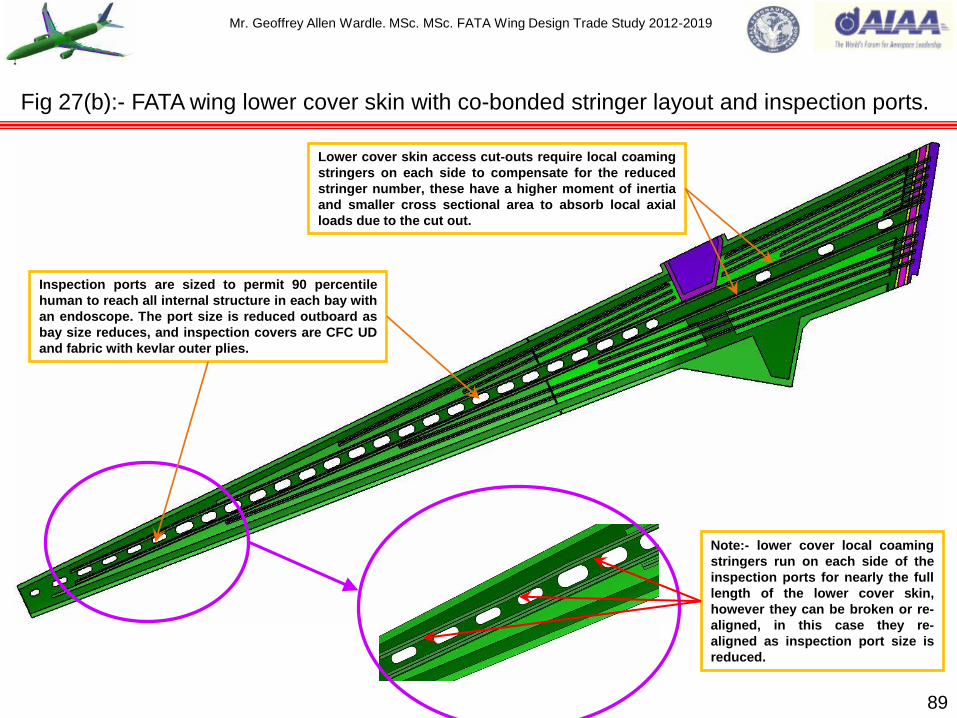
Mr. Geoffrey Allen Wardle. MSc. MSc. FATA Wing Design Trade Study 2012-2019
89
Fig 27(b):- FATA wing lower cover skin with co-bonded stringer layout and inspection ports.
Note:- lower cover local coaming
stringers run on each side of the
inspection ports for nearly the full
length of the lower cover skin,
however they can be broken or re-
aligned, in this case they re-
aligned as inspection port size is
reduced.
Inspection ports are sized to permit 90 percentile
human to reach all internal structure in each bay with
an endoscope. The port size is reduced outboard as
bay size reduces, and inspection covers are CFC UD
and fabric with kevlar outer plies.
Lower cover skin access cut-outs require local coaming
stringers on each side to compensate for the reduced
stringer number, these have a higher moment of inertia
and smaller cross sectional area to absorb local axial
loads due to the cut out.

Mr. Geoffrey Allen Wardle. MSc. MSc. FATA Wing Design Trade Study 2012-2019
To maintain the aerodynamic smoothness of the external surface Outer Mold Line, of the composite
wing cover skins, the surface is always laid on the tooling face and non-structural surface ply is
added at the tool interface, to ensure smooth OML surface.
CFRP Composite are poor conducting materials and have a significantly lower conductivity than
aluminium alloys, therefore the effects of lightening strikes are an issue in composite airframe
component design and a major issue for airworthiness certification of the airframe. The severity of
the electrical charge profile depends on whether the structure is in a zone of direct initial
attachment, a “swept” zone of repeated attachments or in an area through which the current is
being conducted. The aircraft can be divided into three lightening strike zones and these zones for
the aircraft with wing mounted engines is shown in figure 28(a)/(b), and can be defined as follows:-
Zone 1:- Surface of the aircraft for which there is a high probability of direct lightening flash
attachment or exit: Zone 1A- Initial attachment point with low probability of flash hang-on, such
as the nose: Zone 1B- Initial attachment point with high probability of flash hang on, such as a
tail cone.
Zone 2:- Surface of the aircraft across which there is a high probability of a lightening flash
being swept by airflow from a Zone 1 point of direct flash attachment: Zone 2A- A swept-stroke
zone with low probability of flash hang-on, e.g. a wing mid-span: Zone 2B- A swept-stroke zone
with high probability of flash hang-on, such as the wing trailing edge.
Zone 3:- Zone 3 includes all of the aircraft areas other than those covered by Zone 1 and Zone
2 regions. In Zone 3 there is a low probability of any direct attachment of the lightening flash arc,
but these areas may carry substantial current by direct conduction between some Zone1or Zone
2 pairs.
Reference wing box layout key structural members (CFC cover skins).
90

Mr. Geoffrey Allen Wardle. MSc. MSc. FATA Wing Design Trade Study 2012-2019
Zone 3 Indirect effects.
Zone 2 Swept stroke.
Zone 1 Direct strike.
Lightening Strike
Zones on an
aircraft with wing
mounted engines.
Figure 28(a):- Lightening strike risks to composite wing structures with podded engines.
91

Mr. Geoffrey Allen Wardle. MSc. MSc. FATA Wing Design Trade Study 2012-2019
92
Figure 28(b):- Lightening strike risks to composite podded engine aircraft structures.
Zone 1 Direct strike. Zone 1 Direct strike.
Zone 1 Direct strike.
Zone 1 Direct strike.
Zone 2 Swept stroke.
Zone 2 Swept stroke.
Zone 2 Swept stroke.
Zone 2 Swept stroke.
Zone 3 Indirect effects.
Zone 2 Swept stroke.
Zone 3 Indirect effects.
Zone 1 Direct strike.
Zone Key.
Zone 3 Indirect effects.

Mr. Geoffrey Allen Wardle. MSc. MSc. FATA Wing Design Trade Study 2012-2019
93
Lightening effects can be divided into direct effects and indirect effects:-
Direct Effects: - Any physical damage to the aircraft and / or electrical / electronic systems due
to the direct attachment of the lightening channel. This includes tearing, bending, burning,
vaporization or blasting of aircraft surfaces / structures and damage to electrical / electronic
systems.
Indirect Effects: - Voltage and / or current transients induced by lightening in aircraft electrical
wiring which can produce upset and or damage to components within electrical / electronic
systems.
The areas requiring protection in this study are:-
1) Non-conductive composites (e.g. Kevlar, Quartz, fiberglass etc.):
Do not conduct electricity:
Puncture danger when not protected.
2) Advanced composites skins and structures:
Generally non-conductive except for carbon reinforced composites:
Carbon fibre laminates have some electrical conductivity, but still have puncture danger for skin
thickness less than 3.81mm.
3) Adhesively bonded joints:
Usually do not conduct electricity:
Arcing of lightening in or around adhesive and resultant pressure can cause disbonding.
Reference wing box layout key structural members (CFC cover skins).

Mr. Geoffrey Allen Wardle. MSc. MSc. FATA Wing Design Trade Study 2012-2019
4) Anti-corrosion finishes:
Most of them are non-conductive:
Alodine finishes, while less durable, do conduct electricity.
5) Fastened joints:
External fastener heads attract lightening:
Usually the main path of lightening transmission between components:
Even the use of primers and wet sealants will not prevent the transfer of electric current from
hardware to structure.
6) Painted Skins:
The slight insulating effect of paint confines the lightening strike to a localized area so the that
the resulting damage is intensified:
Lightening strikes unpainted composite surfaces in a scattered fashion causing little damage to
thicker laminates.
7) Integral fuel tanks:
Dangers are melt-trough of fasteners or arc plasma blow between fasteners and the resulting
combustion of fuel vapors in the tanks.
Methods of lightening strike protection for composite aircraft wing structures have been developed
and are illustrated in figure 29(a)/(b), these range from layers of aluminium foil on EAP wing, to the
sophisticated copper mesh and fastener insulations used on Eurofighter Typhoon, and the Boeing
787 transport, and the latter will be employed in this study (see also ref 5). 94
Roll and layout of large aircraft wing structural members (cover skins).
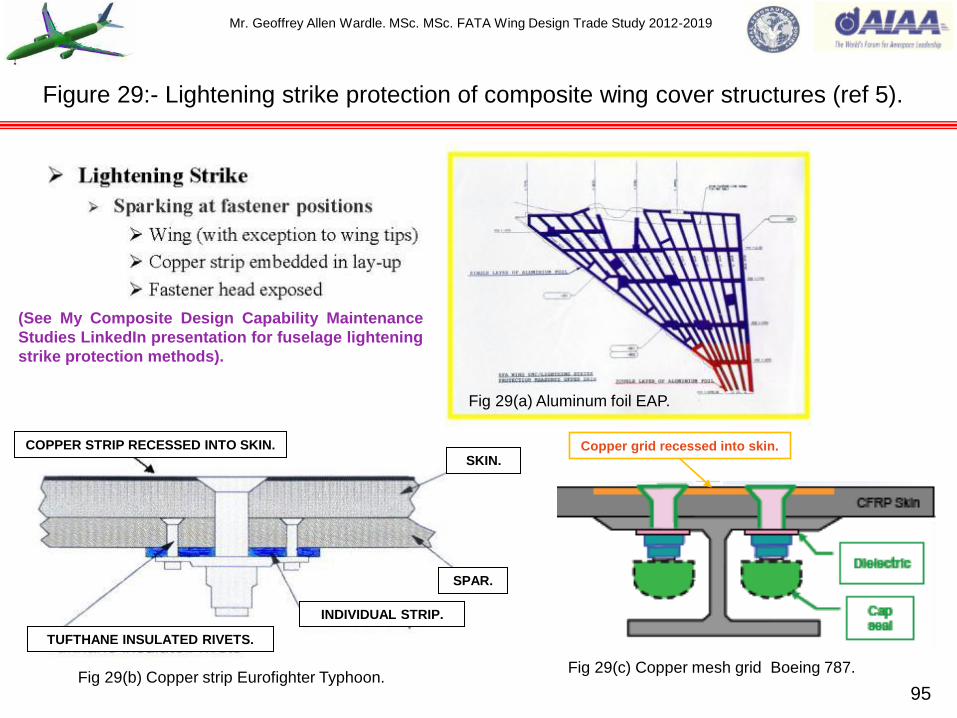
Mr. Geoffrey Allen Wardle. MSc. MSc. FATA Wing Design Trade Study 2012-2019
95
Figure 29:- Lightening strike protection of composite wing cover structures (ref 5).
Copper grid recessed into skin.
Fig 29(a) Aluminum foil EAP.
Fig 29(b) Copper strip Eurofighter Typhoon. Fig 29(c) Copper mesh grid Boeing 787.
COPPER STRIP RECESSED INTO SKIN.
TUFTHANE INSULATED RIVETS.
INDIVIDUAL STRIP.
SKIN.
SPAR.
(See My Composite Design Capability Maintenance
Studies LinkedIn presentation for fuselage lightening
strike protection methods).

Mr. Geoffrey Allen Wardle. MSc. MSc. FATA Wing Design Trade Study 2012-2019
96
Figure 29:- Lightening strike protection of composite fuselages ( A350 and B-787) cont.
Electrical network following frames and floorgrid.
Grounding
Bonding
Voltage
HIRF Protection
CFRP
Lightening Direct Protection:
CFRP + Metallic Mesh.
Figure 29(e) Airbus A350 system.
The Boeing 787 employs
Inter-Woven Wire Fabric
(IWWF) Lightening strike
protection.
Figure 29(d) Boeing B787 system.
* FATA uses an Electro Mesh™ IWWF lightening strike protection.

Mr. Geoffrey Allen Wardle. MSc. MSc. FATA Wing Design Trade Study 2012-2019
Impact damage:- Impact damage in composite airframe components is a major concern of
designers and airworthiness regulators. This is due to the sensitivity of theses materials to quite
modest levels of impact, even when the damage is almost visually undetectable. Detailed
descriptions of impact damage mechanisms and the influence of mechanical damage on residual
strength can be found in ref 6. Horizontal, upwardly facing surfaces are the most prone to hail
damage and should be designed to be at least resistant to impacts in the order of 1.7J (This is a
worst case energy level with a 1% probability of being exceeded by hail conditions). Surfaces
exposed to maintenance work are generally designed to be tolerant to impacts resulting from tool
drops (see figure 30(a)/(b)/(c)). Monolithic laminates are more damage resistant than honeycomb
structures, due to their increased compliance, however if the impact occurs over a hard point such
as above a stiffener or frame, the damage may be more severe, and if the joint is bonded, the
formation of a disbond is possible. The key is to design to the known threat and incorporate surface
plies such as Kevlar or S2 glass cloth see figure 31. Airworthiness authorities categories impact
damage by ease of visibility to the naked eye, rather than by the energy of the impact: - BVID
barely visible impact damage and VID visible impact damage are the use to define impact damage.
Current BVID damage tolerance criterion employed on the B787 is to design for a BVID damage to
a depth of 0.01” to 0.02” which could be caused by a tool drop on the wing, and missed in a general
surface inspection should not grow significantly to potentially dangerous structural damage, before
it is detected at the regular major inspection interval. This has been demonstrated through a
building block test program, and the wing structures so inflicted have maintained integrity at Design
Ultimate Load (DUL). These design criteria are critical airworthiness clearances ACJ 25.603 and
FAA AC20.107A (Composite Aircraft Structures) a full treatment is given below.
97
Roll and layout of large aircraft wing structural members (CFC cover skins).

Mr. Geoffrey Allen Wardle. MSc. MSc. FATA Wing Design Trade Study 2012-2019
From practical experience damage to composite structures due to accidental damage on the flight
line or weather damage cannot be eliminated, therefore composite airframe structures must be
designed with adequate reserves to function safely after damage i.e. be damage tolerant.
Designing for damage tolerance includes selecting damage resistant materials (in particular matrix
resin systems), identifying sources and types of damage, knowledge of damage propagation
mechanisms, and criticality of damage. Damage tolerance in composite airframes depends on
details such as ply layup, frame / rib and stringer pitch attachment details, crack arrest features,
structural redundancy etc. By understanding damage and being able to predict the growth rate, as
well as being able to detect critical damage enables the designer to design a structure that can
withstand given levels of damage that can be detected within regular inspection intervals.
Chart 14 (ref 21) categorises the types of damage which can occur to a composite airframe into
five categories of damage severity as detailed below:-
Category 1:- is allowable damage that may go undetected by scheduled inspections which
includes;- classical low energy BVID; allowable manufacturing defects; and in service damage
which dose not result in degradation of the ultimate load carrying capacity over a reliable
service life of the airframe.
Category 2:- is defined as damage that can be reliably detected by scheduled or directed
inspections. Typical examples of this type being;- visible impact damage; deep scratches;
detectable delamination or disbonding; the resulting residual strength of the composite structure
resulting from this damage must be significantly above the limit load level for the chosen
inspection interval.
98
Classification of impact damage by severity for composite aircraft structures.

Mr. Geoffrey Allen Wardle. MSc. MSc. FATA Wing Design Trade Study 2012-2019
99
Chart 14:- Design load levels vs damage severity for composite aircraft structures.
Design
Load
Level
1.5 Factor
of Safety.
Ultimate
Limit
~ Maximum load
per lifetime.
Continued
safe flight.
Allowable
Damage Limit
(ADL)
Critical Damage
Threshold
(CDT)
Increasing Damage Severity.
Category 1 Damage:- BVID:
Designed for Mfg damage.
Category 2 Damage:- VID: requiring
repair per normal inspection process.
Category 3 Damage:- Obvious damage
found first few flights after occurring:
requiring immediate repair.
Category 4 Damage:- Discrete
damage obvious to flight crew :
requiring repair post flight.
Category 5 Damage:-
Anomalous damage not
covered in design but known
to operations: requiring
immediate repair.

Mr. Geoffrey Allen Wardle. MSc. MSc. FATA Wing Design Trade Study 2012-2019
Category 3:- is damage detectable within a few operational flights by ramp servicing personnel
this would include;- large visual impact damage; damage easily detected by a pre-flight walk
around or drone visual inspection. The design of the airframe to meet Category 3 damage
requires features that provide a sufficient damage tolerance capability that it retains limit load
levels for a short time detection interval.
Category 4:- is discrete damage known to the pilot that limits flight manoeuvres;- this includes
damage due to bird strike; tyre-burst; or sever in-flight hail. This requires sufficient damage
tolerance in the airframe to complete the flight.
Category 5:- is severe damage of the airframe caused by ground or flight conditions not
covered by design criteria this my include;- severe impact with a ground vehicle with an aircraft
fuselage; flight overload condition; in-flight loss of a component e.g. control surface; hard
landings; or blunt impacts. The criticality of this category is highlighted by the fact that there are
no clear visual prior indicators of damage.
Often impacts with ground vehicles can generate Category 2 or 3 damage, which must be
managed with a Certification process i.e. using substantiated scheduled inspections for detection,
and immediate repair action when detected. Alternatively such an impact may result in Category 5,
damage which must be reported and repaired immediately, although this category is outside the
immediate aircraft design Certification process the need to report such damage is identified in
documents such as AMC 20-29. Therefore the boundaries between Category 2/3 and Category 5
damage should be clearly understood. 100
Classification of impact damage by severity for composite aircraft structures.
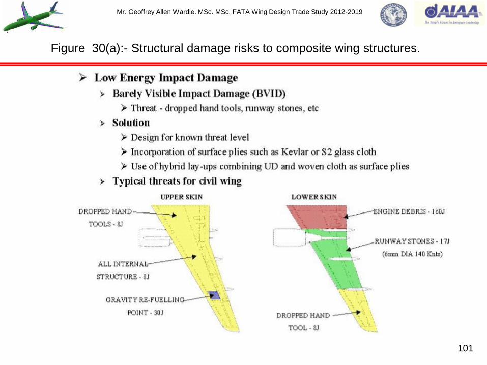
Mr. Geoffrey Allen Wardle. MSc. MSc. FATA Wing Design Trade Study 2012-2019
101
Figure 30(a):- Structural damage risks to composite wing structures.

Mr. Geoffrey Allen Wardle. MSc. MSc. FATA Wing Design Trade Study 2012-2019
102
Figure 30(b):- Structural damage risks to composite fuselage structures.
Cut-out skin reinforcement:-
20:1 ply dropoff ramps
Heavy skin around door special
criteria to resist ramp rash.
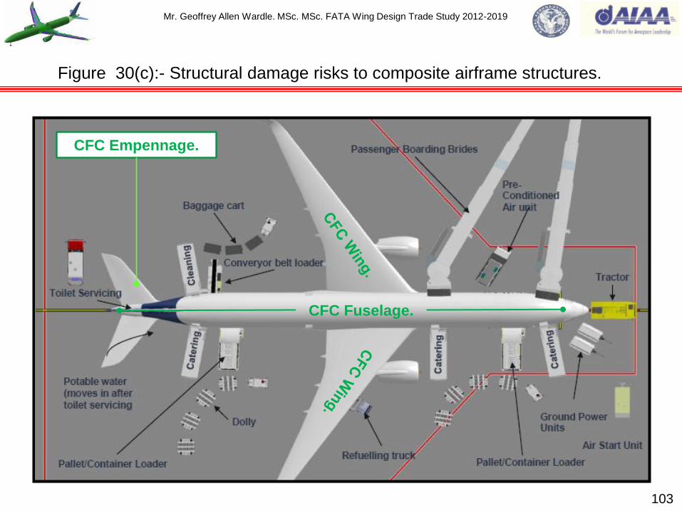
Mr. Geoffrey Allen Wardle. MSc. MSc. FATA Wing Design Trade Study 2012-2019
103
Figure 30(c):- Structural damage risks to composite airframe structures.
CFC Fuselage.
CFC Empennage.

Mr. Geoffrey Allen Wardle. MSc. MSc. FATA Wing Design Trade Study 2012-2019
Figure 31:- Woven Cloth Classifications and surface ply BVID protection options trades.
104

Mr. Geoffrey Allen Wardle. MSc. MSc. FATA Wing Design Trade Study 2012-2019
WING SPARS: - The spars in conjunction with the covers transmit the bending and torsion loads of
the wing box, and typically consists of a web to react vertical shear, and end flanges or caps to
react the bending moment. In modern transports there are two full span spars, and a third stub
spare in wide chord wings to take engine aft pylon mount loads from the pylon drag strut as in the
case of the A300, A330, A340, and A380, and these spars are currently produced as high speed
machined aluminium structures. However the latest generation of large airliners e.g. the Airbus
A350 and Boeing 787 families use composite spars produced by fiber placement as C - sections
laid on INAVR tooling as shown in figure 32, and are typically 88% 45º / -45º ply orientation to react
the vertical shear loads, in the deflected wing case, the outer ply acts in tension supporting the
inner ply which in compression as shown in figure 33, because the fibers are strong in tension but
comparatively weak in compression. The spars can be C section or I section consisting of back to
back co-bonded C-sections, and for this study the baseline reference wing spars are C sections,
and consists of three sub-sections design, due to the size of component based on autoclave
processing route constraints. Although 0° plies are generally omitted from the spar design 90° plies
are employed in approximately 12% of the spar lay-up as shown in figure 34, where there are
bolted joints, tooling hole sites, to react pressure differentials at fuel tank boundaries, and spar
section splicing, figures 35 to 37 show preliminary outboard wing spar design, and figure 38 shows
a spar splice joint concept and 39 shows the outboard spar assembly. The chord-wise location of
the spars is restricted by the numerous leading and trailing edge devices that occupy a significant
portion of the wing chord as shown in figure 20. Generally the front spar should be as far forward as
possible, subject to: - (a) The local wing depth being adequate to enable vertical shear loads to be
reacted efficiently: (b) Adequate nose chord space for leading edge devices and their operating
mechanisms, and de-icing systems. 105
Roll and layout of large aircraft wing structural members (CFC wing spars).

Mr. Geoffrey Allen Wardle. MSc. MSc. FATA Wing Design Trade Study 2012-2019
Therefore the front spar of a two-spar wing torsion box is usually located in the region of 12-18% of
local wing chord.
In two spar modern transport wings the rear spar should be as far aft as possible being limited to
being in front of the trailing edge flaps, control surfaces, and spoilers, and their operating
mechanisms. Thus the rear spar is typically at 55-70% of the chord.
Any intermediate spars are usually spaced uniformly across the chord-wise section except where a
particular pick-up point is required for a powerplant as in the case of the A300, A330/A340/A380,
and the B-747, and auxiliary spars are used to support main landing gear attachment and some
trailing edge surfaces.
Although there have been cases where the width of the structural torsion box has been limited to
give rise to high working stresses in the distributed flanges, and consequent good structural
efficiency, this is achieved at the expense of potential fuel volume. This approach therefore has not
been adopted in these trade studies as the wing is to be employed as a primary integral fuel tank,
and in general for a transport aircraft the opportunity should always be taken to maximize the
potential fuel volume for future growth development.
Spar location should not be stepped in plan layout as this gives rise to offset load paths, but a
change of sweep angle at a major rib position is acceptable.
Returning briefly to metallic ribs, current practice is to integrally machine them from aluminium alloy
rolled or forged plate, this method of construction gives weight savings at reasonable cost over
fabricated construction. Each section of spar has a continuous horizontal stringer crack stopper
introduced approximately 1/3 of the way up the shear web from the predominantly tension flange. 106
Roll and layout of large aircraft wing structural members (CFC wing spars).

Mr. Geoffrey Allen Wardle. MSc. MSc. FATA Wing Design Trade Study 2012-2019
107
Figure 32:- Airbus A350 Composite spar manufacture and assembly.
CFRP Spar C section with apertures for control surface guide rails.
Wing torsion box section with “C” section spars, ribs, and edge control
surface attachment fixtures.
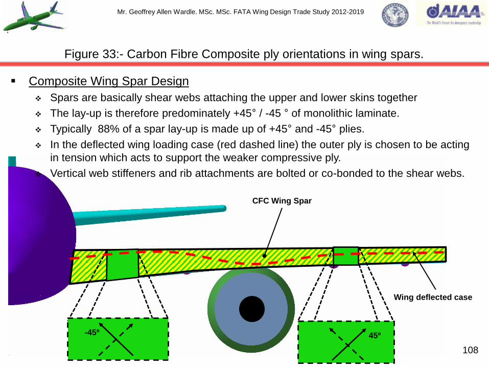
Mr. Geoffrey Allen Wardle. MSc. MSc. FATA Wing Design Trade Study 2012-2019
108
Figure 33:- Carbon Fibre Composite ply orientations in wing spars.
-45º 45º
Composite Wing Spar Design
Spars are basically shear webs attaching the upper and lower skins together
The lay-up is therefore predominately +45° / -45 ° of monolithic laminate.
Typically 88% of a spar lay-up is made up of +45° and -45° plies.
In the deflected wing loading case (red dashed line) the outer ply is chosen to be acting
in tension which acts to support the weaker compressive ply.
Vertical web stiffeners and rib attachments are bolted or co-bonded to the shear webs.
Wing deflected case
CFC Wing Spar

Mr. Geoffrey Allen Wardle. MSc. MSc. FATA Wing Design Trade Study 2012-2019
109
Figure 34:- Carbon Fibre Composite ply orientations in wing spars continued.
90º Plies to react pressure
differentials at fuel tank
boundaries.
90º Plies locally in way of
bolted joints.
Composite Wing Spar Design
0o Plies are generally omitted from spar lay-up however, 90o plies are
added in typically 12% of spar lay-up

Mr. Geoffrey Allen Wardle. MSc. MSc. FATA Wing Design Trade Study 2012-2019
Figure 35:- FATA Outboard Port and Stbd LE CFC Wing Spar and Symmetrical Tool.
Symmetry cut plane.
Port Outboard Leading Edge Spar.
Starboard (Stbd) Outboard Leading Edge Spar.
Two part hollow Outboard Leading
Edge Spar Symmetrical tool with
internal temperature control.
120mm Spar Cut and Trim
Zone to MEP (20mm).
60mm transition zones.
Tool extraction
direction.
Wing
Outboard.
N.B.:-Slat track guide rail cut-outs post lay up activity with
assembly tool hole drilling at extremities rib 35 and splice locations.
(N.B.:- Stbd drill breakout class cloth zones omitted for clarity).
Sacrificial Ply Zone.
Sacrificial Ply Zone.
UP
FWD
OUT BD
Boundary dimensions.
Total spar length = 6.80m :
IB flange to flange height = 0.475m:
OB flange to flange height = 0.407m:
Flange width 224mm 22mm (⅞”) dia bolts in two rows.
110

Mr. Geoffrey Allen Wardle. MSc. MSc. FATA Wing Design Trade Study 2012-2019
Figure 36:- FATA Outboard Port CFC Wing Spar as layup and finished part (preliminary).
10mm Thick Zone.
(46 plies)
7mm Zone
(32 plies)
4mm Zone
(18 Plies)
1:20 Transition zone
(3mm x 60mm)
1:20 Transition zone
(3mm x 60mm)
Slat 7 track guide rail cut-outs.
Fig 30(a) As fibre-placed.
Fig 30(b) As post finishing.
4mm Thick Zone
(18 Plies)
7mm Thick Zone
(32 plies)
10mm Thick Zone.
(46 plies)
Drill breakout Glass Cloth on IML
and OML for spar splice joint.
Drill breakout Glass Cloth on IML for Rib Post
Attachment and tooling holes.
Drill breakout Glass Cloth for track ribs and guide rail
can attachment both IML and OML faces.
Glass Cloth shown in white for clarity.
UP FWD
OUT BD
Tooling Hole
12.7 mm dam
Tooling Hole
12.7 mm dam
Slat track guide rail cut-outs post lay up activity with assembly
tool hole drilling at extremities rib 35 and splice locations. 111

Mr. Geoffrey Allen Wardle. MSc. MSc. FATA Wing Design Trade Study 2012-2019
Figure 37:- FATA Outboard Port / Stbd CFC Wing Spar preliminary part layup.
Zone (1):- 4mm THK 18 plies see Table 6(a)
Zone (2):- 7mmTHK 32 plies see Table 6(b)
Zone (3):- 10mmTHK 46 plies see Table 6(c) (parts 1 and 2)
14ply symmetrical drop
14ply symmetrical drop 112
Based on Carbon / Epoxy 3501/6 QI unidirectional composite tape
material with a ply thickness of 0.21336mm (see table 6(a),6(b),and 6(c)).
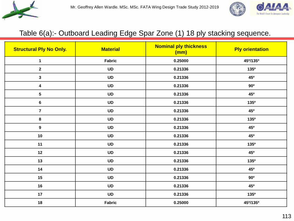
Mr. Geoffrey Allen Wardle. MSc. MSc. FATA Wing Design Trade Study 2012-2019
Structural Ply No Only. Material Nominal ply thickness
(mm) Ply orientation
1 Fabric 0.25000 45º/135º
2 UD 0.21336 135º
3 UD 0.21336 45º
4 UD 0.21336 90º
5 UD 0.21336 45º
6 UD 0.21336 135º
7 UD 0.21336 45º
8 UD 0.21336 135º
9 UD 0.21336 45º
10 UD 0.21336 45º
11 UD 0.21336 135º
12 UD 0.21336 45º
13 UD 0.21336 135º
14 UD 0.21336 45º
15 UD 0.21336 90º
16 UD 0.21336 45º
17 UD 0.21336 135º
18 Fabric 0.25000 45º/135º
113
Table 6(a):- Outboard Leading Edge Spar Zone (1) 18 ply stacking sequence.
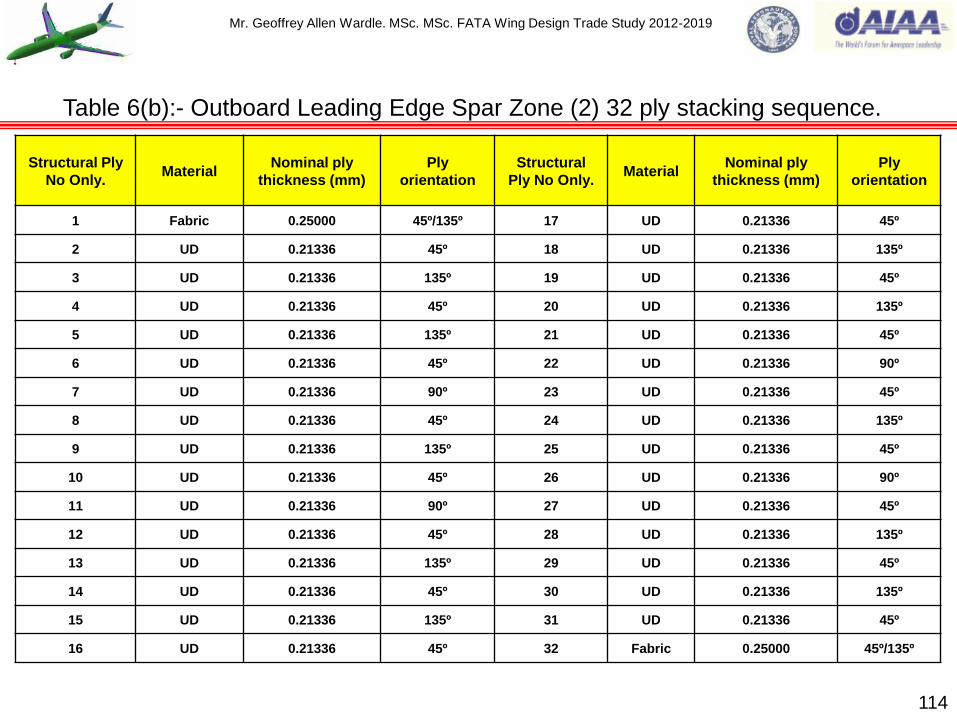
Mr. Geoffrey Allen Wardle. MSc. MSc. FATA Wing Design Trade Study 2012-2019
Structural Ply
No Only. Material
Nominal ply
thickness (mm)
Ply
orientation
Structural
Ply No Only. Material
Nominal ply
thickness (mm)
Ply
orientation
1 Fabric 0.25000 45º/135º 17 UD 0.21336 45º
2 UD 0.21336 45º 18 UD 0.21336 135º
3 UD 0.21336 135º 19 UD 0.21336 45º
4 UD 0.21336 45º 20 UD 0.21336 135º
5 UD 0.21336 135º 21 UD 0.21336 45º
6 UD 0.21336 45º 22 UD 0.21336 90º
7 UD 0.21336 90º 23 UD 0.21336 45º
8 UD 0.21336 45º 24 UD 0.21336 135º
9 UD 0.21336 135º 25 UD 0.21336 45º
10 UD 0.21336 45º 26 UD 0.21336 90º
11 UD 0.21336 90º 27 UD 0.21336 45º
12 UD 0.21336 45º 28 UD 0.21336 135º
13 UD 0.21336 135º 29 UD 0.21336 45º
14 UD 0.21336 45º 30 UD 0.21336 135º
15 UD 0.21336 135º 31 UD 0.21336 45º
16 UD 0.21336 45º 32 Fabric 0.25000 45º/135º
114
Table 6(b):- Outboard Leading Edge Spar Zone (2) 32 ply stacking sequence.

Mr. Geoffrey Allen Wardle. MSc. MSc. FATA Wing Design Trade Study 2012-2019
Structural Ply No Only. Material Nominal ply thickness (mm) Ply orientation
1 Fabric 0.25000 45º/135º
2 UD 0.21336 135º
3 UD 0.21336 45º
4 UD 0.21336 135º
5 UD 0.21336 45º
6 UD 0.21336 135º
7 UD 0.21336 45º
8 UD 0.21336 135º
9 UD 0.21336 45º
10 UD 0.21336 135º
11 UD 0.21336 45º
12 UD 0.21336 135º
13 UD 0.21336 45º
14 UD 0.21336 90º
15 UD 0.21336 45º
16 UD 0.21336 135º
17 UD 0.21336 45º
18 UD 0.21336 90º
19 UD 0.21336 45º
20 UD 0.21336 135º
21 UD 0.21336 45º
22 UD 0.21336 135º
23 UD 0.21336 45º
115
Table 6(c):- Outboard Leading Edge Spar Zone (3) 46 ply stacking sequence (part 1).

Mr. Geoffrey Allen Wardle. MSc. MSc. FATA Wing Design Trade Study 2012-2019
Structural Ply No Only. Material Nominal ply thickness (mm) Ply orientation
24 UD 0.21336 45º
25 UD 0.21336 135º
26 UD 0.21336 45º
27 UD 0.21336 135º
28 UD 0.21336 45º
29 UD 0.21336 90º
30 UD 0.21336 45º
31 UD 0.21336 135º
32 UD 0.21336 45º
33 UD 0.21336 90º
34 UD 0.21336 45º
35 UD 0.21336 135º
36 UD 0.21336 45º
37 UD 0.21336 135º
38 UD 0.21336 40º
39 UD 0.21336 135º
40 UD 0.21336 45º
41 UD 0.21336 135º
42 UD 0.21336 45º
43 UD 0.21336 135º
44 UD 0.21336 45º
45 UD 0.21336 135º
46 Fabric 0.25000 45º/135º
116
Table 6(c):- Outboard Leading Edge Spar Zone (3) 46 ply stacking sequence (part 2).

Mr. Geoffrey Allen Wardle. MSc. MSc. FATA Wing Design Trade Study 2012-2019
117
Proposed C section wing spar section splice joint design methodology.
Due to the ± 5% thickness control limitations on composite parts the spar splice joints will have to
be multi component adjustable assemblies. Using a mirrored internal female tool on which port and
starboard spar sets are formed by fibre placement and then split on the long axis. Sacrificial plies
will be used on the external mating surfaces and machined back using the methods shown in
figures 64 and 65. Although this adds a further manufacturing stage it would reduce joint complexity
and weight. The material will be choice will be Titanium alloy Ti 6Al 4V. Full joint design is shown in
figure 38 (a) through (d) and proposed installation shown in figures 38 (e) and (f) (notional sizing
6mm thk on initial analysis). Figures 39(a) and 39(b) show the outboard to mid leading edge spar
assembly.
The concept is for a two part assembly the insert section mounted on the IML spar web and flange
faces and the doubler mounted on the spar web OML, the web attachment being made with 30 Hi-
Lok Ti alloy PAN head bolts for a high shear strength joint, with head washers, mounted OML to
IML through pre-drilled holes in both the insert section and the doubler plate, three vertical rows are
used each side of the splice, because the end fasteners will load up first and hence yield early. The
spars currently would be pilot drilled with final holes drilled on assembly, post machining of their
sacrificial ply zones. Interface sealant would for the whole assembly will be Polysulphide (PRC) as
per figure 70 for tank sealing. The flange to spar and cover skin joint is made using two rows of
NAS 1221 Ti alloy Countersunk bolts, and domed (flange IML) bonded anchor nuts with dielectric
seals beneath the nut plate as per figure 29(c) for lightening strike protection. The wing cover skins
would also be tailored to carry the balance of the flange shear loads from the splice joint. Currently
the flange holes would be pilot drilled for drill on assembly as per spar flange drilling in tooling, the
rib post would be pilot drilled for drill on assembly.

Mr. Geoffrey Allen Wardle. MSc. MSc. FATA Wing Design Trade Study 2012-2019
118
Figure 38(a) (b) (c) (d):- Proposed C section wing spar section splice joint.
A
2 x rows of NAS 1221, 22mm (⅞”) Countersunk Ti Flange bolts.
6 x rows of Hi-Lok, 22mm (⅞”) PAN head Ti Web bolts. Fig 38 (a) Inboard Front (View on B)
Integral rib post
Fig 38(b) Top (View on A)
B
Fig 38 (d) Doubler (View on C)
C
3d to edge of spar TYP.
2d to edge of part TYP.
3 x vertical rows of Hi-
Lok, 22mm (⅞”) PAN
head Ti Web bolts
each side of splice
(pre-drilled).
3d to edge of spar TYP.
2d to edge of part TYP.
Fig 38 (c) ISO Splice plate.
2.5d to edge of part TYP.

Mr. Geoffrey Allen Wardle. MSc. MSc. FATA Wing Design Trade Study 2012-2019
Figure 38 (e) (f):- Proposed C section wing spar section splice joint methodology.
Fig 38(e):- Outboard Leading Edge Splice
plate assembly looking on IML.
Fig 38(f):- Outboard Leading Edge Splice
plate assembly looking on OML.
Splice plate pre drilled installed with integral rib
post (flange drilled on assembly).
Leading Edge Spar Mind Section
Joint (sacrificial ply zone).
Leading Edge Spar
Outboard Section Joint
(sacrificial ply zone).
Top cover skin tailored to react
OML flange shear loads.
Bottom cover skin tailored to react
OML flange shear loads.
Leading Edge Spar
Outboard Section Joint
(sacrificial ply zone).
Leading Edge Spar Mind Section
Joint (sacrificial ply zone).
Splice doubler pre drilled installed.
FWD
UP
OUT BD
OUT BD
UP
AFT
119

Mr. Geoffrey Allen Wardle. MSc. MSc. FATA Wing Design Trade Study 2012-2019
120
Figure 39(a):- FATA Outboard Port / Stbd CFC Wing Spar assembly.
Port Mid Section
Leading Edge Spar.
Port Outboard Section
Leading Edge Spar.
Ti alloy Rib Post 29
Ti alloy Rib Post 30
Ti alloy Rib Post 31
Ti alloy Rib Post 32 Ti alloy Rib Post 33 Ti alloy Rib Post 34
Assembly proposal.
Spar section is to be mounted in jig tool with
pre drilled web fastener holes for rib posts
based on CAD (Catia model). Rib posts with
web pre drilled web fastener holes are then
individually mounted in place with a robot end
effector gripping the rib web, whilst an other
end effector tool insets the bolts IML to OML,
and attaches the collars to complete assembly.
Flange fastener hole would be drilled in
assembly as per the AWBA (see My Robot
Kinematics Presentation LinkedIn).

Mr. Geoffrey Allen Wardle. MSc. MSc. FATA Wing Design Trade Study 2012-2019
121
Figure 39(b):- FATA Outboard Port / Stbd CFC Wing Spar assembly.
Pre-drilled web fastener
holes 22mm (⅞”).
Flange fastener holes
drilled on assembly
22mm (⅞”).
Initial sizing 6mm
web / flange 4mm
rib landing web.
OB Leading Edge Ti Rib Post Typical.
OB Leading Edge section to Mid
Leading Edge section Splice joint. Port Outboard Section
Leading Edge Spar.
UP
FWD
IN BD

Mr. Geoffrey Allen Wardle. MSc. MSc. FATA Wing Design Trade Study 2012-2019
WING RIBS:- The ribs, an example is shown in figure 40, maintain the determined aerodynamic
shape of the wing cross-section (chord), limit the length of skin stringers or integrally stiffened
panels to an efficient column compressive strength, and to structurally transmit chord-wise loads
across the span-wise torsion box. Hinges and supports for secondary lifting surfaces, flight controls,
are located at the ends of relevant ribs. Ribs also provide attachment points for main landing gear,
powerplants, and act as fuel tank boundaries. Overall the ribs stabilize the spars and skins in span-
wise bending.
The applied loads the ribs distribute are mainly distributed surface air loads and / or fuel loads
which require relatively light internal ribs to carry trough or transfer these loads to the main spar
structures. The loads carried by the ribs are as follows: - (1) The primary loads acting on the rib are
the external air loads which they transfer to the spars: (2) Inertia loads e.g. fuel, structure,
equipment, etc.: (3) Crushing loads due to flexure bending, when the wing box is subjected to
bending loads, the bending of the box as a whole tends to produce inward acting loads on the wing
ribs figure 40(d), and since the inward acting loads are oppositely directed on the tension and
compression side they tend to compress the ribs: (4) Redistributes concentrated loads such as
from an engine pylon, or undercarriage loads to wing spars and cover skins: (5) Supports members
such as cover skin – stringer panels in compression and shear: (6) Diagonal tension loads from the
cover skin – when the wing skin wrinkles in a diagonal tension field the ribs act as compression
members: (7) Loads from changes in cross section e.g. cut outs, dihedral changes, or taper
changes.
122
Roll and layout of large aircraft wing structural members (wing ribs).
Mr. Geoffrey Allen Wardle. MSc. MSc. FATA Wing Design Trade Study 2012-2019
Rib construction for large transports fall into three types and this off course influences the way in
which they distribute the external loads and reaction forces categorized above, the three types of
metallic construction are:- (a) Truss type: (b) Shear web type: (c) Webs stiffened ribs with fuel
transfer holes (shown in figures 40(a) and 40(c) is the FATA baseline Al/Li Rib 12).
The way in which the rib structure resists the external loads and reaction forces the rib is subjected
to is dependent on the construction methods employed as outlined below:-
In the truss rib construction distributed external loads and reaction forces are applied as
concentrated loads at the joints and the structure can be analysed as a simple truss. The outer
members on which the distributed loads are relied upon to transfer these loads, in shear, to the
points where they can then be considered as concentrated loads. These outer members are
therefore subjected to combined bending and compression or bending and tension, structural
analysis of one such rib is given in Workbook 2.
Shear web rib construction is usually employed in to either distribute the concentrated loads,
such as the engine pylon or main landing gear, or to distribute fuel tank bulkhead boundary
pressure loads to the shear beams.
Web with lightening hole and stiffener construction are used to resist bending moments by the
rib cap members and shear by the web.
Simple beam structural analysis can be applied to ribs design checking the following:- Shear in the
web, or axial loads in the truss members: Rib cap bending loads: Shear attachment to the spars
and wing cover skins: Tension attachment of the wing cover skins: Crushing loads: Shear load
effects from local cut outs: Fuel pressure loads which are normal to the rib plane. 123
Roll and layout of large aircraft wing structural members (Al Li wing ribs).

Mr. Geoffrey Allen Wardle. MSc. MSc. FATA Wing Design Trade Study 2012-2019
Figure 40(a) / (b):- Inner Metallic rib 12 design for FATA aircraft baseline study in Al/Li.
124
Fig 36(a):- Advanced metallic aircraft rib 12, for the FATA baseline study
using the methodology employed in the B787 and for composite wing
skins with CFRP „I‟ stringers using the contour of the rib flange for
attaching both skin and bonded stringer to the rib (stressing for FATA
baseline ribs sizing is in work this model uses nominal sizing).
FWD
UP
IN BD
Fig 40(b):- Boeing 787 metallic rib with „I‟ stiffeners.
Leading edge spar bath tub attachment.
Ventilation holes.
Fwd Mass Flow Fuel Transfer
Hole with web reinforcement.
Aft Mass Flow Fuel Transfer Hole
with web reinforcement.
Low Level Fuel Transfer Hole
with web reinforcement.
Low Level Fuel Transfer Holes
with web reinforcement typical.
Trailing edge spar bath tub attachment .
Shear load web stiffeners
typical.
Fuel Transfer System
Penetration Holes with
web reinforcement.
Web panel breakers
typical.
Low Level Fuel Transfer Hole
with web reinforcement.
Initial design weight in Al/Li = 78.581kg.

Mr. Geoffrey Allen Wardle. MSc. MSc. FATA Wing Design Trade Study 2012-2019
125
Figure 40(c) / (d):- Inner Metallic rib design for FATA baseline study in Al/Li.
Fig 40(d):- Wing crushing loads due to flexure bending.
Leading edge spar. Wing top cover skin.
Wing bottom cover skin.
Wing bottom skin stringers.
Fwd coaming skin stringer.
Low level fuel
Transfer Hole.
Aft fuel drain.
Fwd ventilation. Aft ventilation.
Fig 40(c):- Metallic Al/Li Rib 12 installed in FATA wing view looking outboard.
(N.B. Low level fuel transfer holes and ventilation holes double as tooling holes
sizing and location of all ventilation and fuel transfer holes is based on TSM-08).
Trailing edge spar. Wing top skin stringers.
Fwd fuel drain.
Low level fuel
Transfer Holes.
Mr. Geoffrey Allen Wardle. MSc. MSc. FATA Wing Design Trade Study 2012-2019
Both the FATA Prime baseline, and the Developed PRSEUS FATA wing, employ carbon fibre
composite ribs at 11 locations, figures 41and 42 illustrate the basic rules for interface strategy.
In the case of the FATA Prime baseline wing CFC ribs shown in figures 43, and 44 they have
top and bottom flanges, with an integral trailing edge spar cleat and a leading edge tab, the web
is stiffened with integral pad-up zones to add buckling resistance under compressive loading,
the webs have standard fuel transfer and vent holes. Both top and bottom flanges of the rib are
bolted to the upper and lower wing cover skins through the stringer flanges with tolerance
compensation, and these flanges are joggled to allow for the interface with stringer flange toes
and fitted with packers (see figure 25) these are manufactured on an open male tool and Spring
In will be addressed with mould compression and process control based on statistical analysis.
A variation to this configuration is shown in figures 45 and 46 where fully tapered co-bonded
stringer flange toes are employed reducing peel stress further and eliminating the joggle
feature.
In the case of the Developed PRSEUS FATA wing CFC ribs shown in figures 47 to 51, they
have a top flange only with a separate stitched bottom integrated flange which is bolted to the
rib web as a proposed method of arresting delamination growth in the lower wing skin in the
same way as the stitched stringers concept, which has been successfully demonstrated through
the joint NASA / Boeing technology demonstration program (reference 2). This structural
assembly concept has the additional advantage of eliminating the need to joggle the rib bottom
flange to accommodate the stringer feet reducing the risk of over dimensioning the tolerance
chain and the effects of laminate thickness variations, and is aligned with LOCOMACH research
(reference 19).
126
Roll and layout of large aircraft wing structural members (CFC wing ribs).

Mr. Geoffrey Allen Wardle. MSc. MSc. FATA Wing Design Trade Study 2012-2019
127
Figure 41:- Basic rules of interface design strategy FATA composite structure.
1) Design critical joining areas to
permit elastic gap closure during
assembly.
2) Avoid over dimension in the flange
design.
3) Ensure that laminate thickness
variations are not critical for the
tolerance chain.
(1)
(2)
(3)

Mr. Geoffrey Allen Wardle. MSc. MSc. FATA Wing Design Trade Study 2012-2019
128
Figure 42:- Geometric accuracy strategy FATA composite rib structures.
SPRING IN
SCATTER
SHRINKAGE
As covered in reference 10, the major issues influencing the ability to
control and maintain the geometrical accuracy of production composite
components are:- Spring In component deformation: Spring In Scatter:
and Part thickness Shrinkage. Tooling design to reduce these effects is
detailed in reference 10 section 4.
In order to determine the extent of these problems for the individual ribs
the Pheno-numerical strategy to predict Process Induced Deformation
developed in reference 18 is proposed using:- Simulation of systematic
“Spring In” deformation for the planned processing operation, and for the
“Spring In scatter” using statistical identification of scatter sensitive
production parameters. The shrinkage phenomenon will be dealt with by
experimental identification of modified Coefficient of Thermal Expansion
CTE and process sensitivity.
The desired outcomes of the application of the PRSEUS integrated rib lower flange concept are:-
an improvement in composite rib interface strategy for wing box assembly: comparable component
geometrical accuracy to Al Li wing ribs: structural weight reduction: and reduced manufacturing
costs.
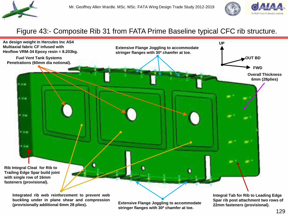
Mr. Geoffrey Allen Wardle. MSc. MSc. FATA Wing Design Trade Study 2012-2019
129
Figure 43:- Composite Rib 31 from FATA Prime Baseline typical CFC rib structure.
UP
FWD
OUT BD
Overall Thickness
6mm (28plies)
Rib Integral Cleat for Rib to
Trailing Edge Spar build joint
with single row of 16mm
fasteners (provisional).
Extensive Flange Joggling to accommodate
stringer flanges with 30º chamfer at toe.
Integrated rib web reinforcement to prevent web
buckling under in plane shear and compression
(provisionally additional 6mm 28 plies). Extensive Flange Joggling to accommodate
stringer flanges with 30º chamfer at toe.
Integral Tab for Rib to Leading Edge
Spar rib post attachment two rows of
22mm fasteners (provisional).
Fuel Vent Tank Systems
Penetrations (60mm dia notional).
As design weight in Hercules Inc AS4
Multiaxial fabric CF infused with
Hexflow VRM-34 Epoxy resin = 8.203kg.

Mr. Geoffrey Allen Wardle. MSc. MSc. FATA Wing Design Trade Study 2012-2019
130
Figure 44:- Composite Rib 31 from FATA Prime Baseline typical CFC rib assembly.
(N.B.:- As with the metallic ribs the effort is made to use the low level fuel transfer holes
and ventilation holes as assembly tooling holes.)
Aft Low level fuel
transfer hole.
Wing Bottom Cover Skin.
Leading Edge
CFC spar.
Trailing Edge
CFC spar.
Wing Top Cover Skin. Aft ventilation hole.
Fwd Low level fuel
transfer hole. Mid Low level fuel
transfer hole.
Aft ventilation.
Leading Edge
Ti Rib Post.
Fwd ventilation.
Aft fuel drain.
Top Cover Skin Co-bonded Stringers.
Fwd Coaming Skin Co- bonded
Stringer.
Aft Coaming Skin Co-bonded
Stringer.
Fwd fuel drain.
Figure 44(b):- Aft Coaming Skin Stringer showing
glass packer zones typical for all stringers.
Glass packers
UP
FWD
Fwd ventilation hole.
Top Cover Skin 20mm fasteners.
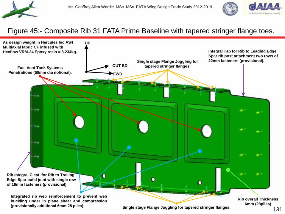
Mr. Geoffrey Allen Wardle. MSc. MSc. FATA Wing Design Trade Study 2012-2019
131
Figure 45:- Composite Rib 31 FATA Prime Baseline with tapered stringer flange toes.
UP
FWD
OUT BD Single stage Flange Joggling for
tapered stringer flanges.
Rib Integral Cleat for Rib to Trailing
Edge Spar build joint with single row
of 16mm fasteners (provisional).
Integrated rib web reinforcement to prevent web
buckling under in plane shear and compression
(provisionally additional 6mm 28 plies). Single stage Flange Joggling for tapered stringer flanges.
Fuel Vent Tank Systems
Penetrations (60mm dia notional).
Rib overall Thickness
6mm (28plies)
Integral Tab for Rib to Leading Edge
Spar rib post attachment two rows of
22mm fasteners (provisional).
As design weight in Hercules Inc AS4
Multiaxial fabric CF infused with
Hexflow VRM-34 Epoxy resin = 8.234kg.

Mr. Geoffrey Allen Wardle. MSc. MSc. FATA Wing Design Trade Study 2012-2019
132
Figure 46:- Composite Rib 31 FATA Baseline with tapered stringer toe rib assembly.
Aft ventilation.
Aft ventilation hole.
Fwd ventilation hole.
Top Cover Skin Co-bonded Stringers.
Fwd ventilation.
Trailing Edge
CFC spar.
Aft fuel drain.
Aft Low level fuel
transfer hole. Mid Low level fuel
transfer hole. Fwd Low level
fuel transfer hole. Aft Bottom Cover Skin Co-
bonded Coaming Stringer. Fwd Bottom Cover Skin Co-
bonded Coaming Stringer.
Leading Edge
Ti Rib Post.
Leading Edge
CFC spar.
Wing Top Cover Skin.
Wing Bottom Cover Skin.
UP
FWD
Figure 46(b):- Tapered Skin Stringer, note
packers required under bonded anchor nuts
Typical.
(N.B.:- As with the metallic ribs the effort is made to use the low level fuel transfer
holes and ventilation holes as assembly tooling holes.)
Fwd fuel drain.
Top Cover Skin 20mm fasteners.
Mr. Geoffrey Allen Wardle. MSc. MSc. FATA Wing Design Trade Study 2012-2019
Proposed assembly methodology for Stitched Split Rib 31 subsequent integration into the PRSEUS
tapered stringers / skin assembly is shown below in figures 48 to 50 follows these procedural
stages:-
1) Production of the Rib Integral Flange / Web unit comprises the bonding of two C-section
preforms, a cleavage filler and a tear strip into one unit using tack adhesive film as shown in
figure 48(a). The resulting unit then has the stringer cut-outs and low-level fuel transfer holes
removed, following this the unit is mounted in the stitching tool and the web is stitched with two
rows of 1200 Denier thread infused with Vectran DMS 2479 Type 2 Class 1 VRM epoxy resin,
as shown in figure 48(b). The resulting unit can then be mounted and attached in place on the
Lower Wing Cover Skin, after the PRSEUS lower skin Stringers have been attached figure
48(c) all in the dry condition.
2) The Rib Integral Flange / Web unit when mounted over the stringers is stitched into position
using four rows of 1200 Denier thread infused with Vectran DMS 2479 Type 2 Class 1 VRM
epoxy resin, as shown in figure 49 the inboard stitching rows are angled at 45º so that
additional interlocking is achieved below the web on the Lower Wing Cover Skin OML this aides
the distribution of loads in the Web area. The complete Lower Wing Cover Skin mounted on the
OML tool and bagged is then infused with DMS 2436 Type 2 Class 72 (grade A) Hexflow epoxy
resin using the Boeing CAPRI vacuum assisted resin infusion process, and cured.
3) The Upper Rib section swung into place having been inserted between the leading and trailing
edge spars and is bolted to the Leading Edge Rib Post and integral rib cleat is bolted to the
trailing edge spar. The resulting assembly is bolted to the Rib Integral Flange / Web Unit as
shown in figure 50. 133
Roll and layout of large aircraft wing structural members (CFC wing ribs).

Mr. Geoffrey Allen Wardle. MSc. MSc. FATA Wing Design Trade Study 2012-2019
134
Figure 47:- Composite Rib 31 FATA Split Rib, with PRSEUS tapered stringers.
As design weight in Hercules Inc AS4 Multiaxial fabric
CF infused with Hexflow VRM-34 Epoxy resin = 7.22kg.
UP
FWD
OUT BD Fuel Vent Tank Systems
Penetrations (60mm dia notional).
Rib Integral Cleat for Rib to Trailing
Edge Spar build joint with single row
of 16mm fasteners (provisional).
Single stage Flange Joggling for
tapered stringer flanges.
Integral Tab for Rib to Leading Edge
Spar rib post attachment two rows of
22mm fasteners (provisional).
Integrated rib web reinforcement to prevent web
buckling under in plane shear and compression
(provisionally additional 6mm 28 plies).
Rib overall Thickness
6mm (28plies)
Reduced cutout width for PRSEUS
Cover Skin Stringers.
Flange attachment fasteners 14mm (provisional).

Mr. Geoffrey Allen Wardle. MSc. MSc. FATA Wing Design Trade Study 2012-2019
135
Figure 48:- Composite Rib 31 Stitched Integral Flange / Web Preform assembly.
Tare Strip
(1.5mm)
Figure 48(a)
J-preform
(4mm)
J-preform
(4mm)
Cleavage filler Tack adhesive film
Two rows of web stitching on three zones.
(Modified lock type)
Aft Coaming Stringer Cut-out
Figure 48(b)
Low level fuel transfer holes.
Figure 48(c)
Aft Coaming Stringer Section
Fwd Coaming Stringer Section
Section of lower cover skin
(representative)
Fwd Coaming Stringer Cut-out

Mr. Geoffrey Allen Wardle. MSc. MSc. FATA Wing Design Trade Study 2012-2019
136
Figure 49:- Composite Rib 31 Stitched Integral flange and PRSEUS Coaming stringers.
Figure 49(a) Side view on (B)
Figure 49(b) Plan view
Figure 49(c) Front view on (A)
(Coaming Stringers omitted for clarity.)
(A)
(B) Aft Coaming Stringer Section Fwd Coaming Stringer Section
Flange to Lower Cover Skin Stitching 4 rows 2 per side on all three zones
( Modified Lock type.)
Two rows of web stitching on three zones.
(Modified lock type) Stitching Vectors
OUT BD
FWD

Mr. Geoffrey Allen Wardle. MSc. MSc. FATA Wing Design Trade Study 2012-2019
137
Figure 50:- Proposed Rib 31/ Flange / Stringer and Spar unit assembly sequence.
(A) :- Post mounting and stitching operations on the PRSEUS Coaming Preform Stringers to
the Lower Wing Cover Skin, the Integral Rib Flange / Web Preform section is mounted and
stitched in place and the resulting assembly is infused with Hexflow VRM-34 Epoxy Resin
using the Boeing CAPRI vacuum assisted resin infusion process.
(B) :- The Rib Post is Bolted on to the Leading Edge Spar, and Split Rib Top
section is inserted between the Leading and Trailing Edge spars and rotated
into position forming with the other ribs the complete build unit.
Lower Wing Cover Skin
section.
Aft Coaming Stringer Section
Fwd Coaming Stringer Section
Integral Rib Flange / Web Preform
Section.
(C) :- The complete Outboard Wing Integral Structure
Build Unit is lowered into the Lower Wing Cover Skin,
and bolted into place, post systems integration with
the Mid Wing Integral Structure Build Unit the Upper
Wing Cover Skin with PRSEUS stringers attached
can be lowered in place on to the assembly and
bolted into place.
Trailing Edge Spar section.
Leading Edge Spar section.
Rib 31 top section. Rib 31 Post.

Mr. Geoffrey Allen Wardle. MSc. MSc. FATA Wing Design Trade Study 2012-2019
138
Figure 51:- Composite Rib 31 FATA Prime with PRSEUS tapered stringer assembly.
Trailing Edge
CFC spar.
UP
FWD
Leading Edge
CFC spar.
Wing Top Cover Skin.
Wing Bottom Cover Skin.
Leading Edge
Ti Rib Post.
Fwd Bottom Cover Skin PRSEUS
Coaming Stringer. Aft Bottom Cover Skin PRSEUS
Coaming Stringer.
Fwd Low level
fuel transfer hole. Mid Low level
fuel transfer hole.
Aft Low level fuel
transfer hole.
Aft fuel drain.
Top Cover Skin PRSEUS Stringers. Top Cover Skin 20mm fasteners.
Aft ventilation. Aft ventilation hole. Fwd
ventilation.
Fwd ventilation hole.
Fwd fuel
drain.

Mr. Geoffrey Allen Wardle. MSc. MSc. FATA Wing Design Trade Study 2012-2019
The rib alignment and rib spacing has to be established at an early stage in the preliminary design
phase, since the weight of the ribs contributes significantly to the total wing box structural weight,
therefore rib layout configurations were run through the AeroDYNAMIC™ MDO toolkit at the start of
the wing design process. It is advantageous to select a lager rib spacing; equal structural weight it
leads to cost savings and less fatigue risks. The rib spacing will increase with the depth of the wing
box, hence considering the typical wing which is tapered in planform and depth, the optimum wing
structure would have a variable rib spacing with the maximum spacing inboard and minimum
spacing outboard.
The wing rib arrangement outside the root interface is critical for designing the compression
structural stability of the wing box members especially the upper cover skin, and the rib spacing is
as important as the root joint design, ideally the rib spacing should be determined to ensure
adequate overall buckling support to the distributed flanges, and this requirement gives the
maximum theoretical pitch of the ribs. However other practical considerations are likely to
determine the actual rib locations such as:- (a) Hinge positions for control surfaces and attachment
/ operating points for flaps, slats, and spoilers: (b) Attachment locations of powerplants and landing
gear structure (and stores for military derivative airframes P-8 etc.): (c) The need to prevent or
postpone skin local shear or compression buckling, as opposed to overall buckling: (d) Ends of
integral fuel tanks where a closing rib is required.
For the swept wing configuration there are two main options for rib alignment which are:- (1) In the
direction of flight shown in figure 52(a) and: (2) Orthogonal to the rear spar direction shown in figure
52(b). 139
Roll and layout of large aircraft wing structural members (wing ribs).

Mr. Geoffrey Allen Wardle. MSc. MSc. FATA Wing Design Trade Study 2012-2019
140
Figure 52:- Rib layout options for large swept wing aircraft.
Fig 52(a) Ribs laid out in direction of flight. Fig 52(b) Ribs laid perpendicular to the rear spar.
Front spar.
Rear spar.
Auxiliary spar.
Ribs.
Front spar.
Rear spar.
Auxiliary spar.
Ribs.
Front spar.
Rear spar. Auxiliary spar.
Transition
Rib.
Fig 52(c) Ribs laid in hybrid fan from line of flight to perpendicular to rear spar.
Perpendicular
Ribs.
Fight line
Rib.

Mr. Geoffrey Allen Wardle. MSc. MSc. FATA Wing Design Trade Study 2012-2019
While the direction of flight alignment for the ribs, option 1 (figure 52(a)) gives greater torsional
stiffness, but the ribs are heavier, connections are more complex, and in general the disadvantages
outweigh the stiffness gains. The orthogonal direction alignment of the ribs, option 2 (figure 52(b))
with the ribs at right angles to the rear spar is more satisfactory in facilitating hinge pick-ups, but
they cause layout issues in the root regions. It is possible to overcome these issues by fanning the
ribs so that the alignment changes from perpendicular to the spars outboard portion of the wing to
stream-wise over the inboard portion of the wing, (with the special exceptions for powerplant
mounting ribs which are best located in the fight direction), as shown in figure 52(c), and it was this
hybrid configuration which gave the best MDO analysis results and was selected for the baseline
wing configuration.
FIXED SECONDARY STRUCTURE:- A fixed leading edge is usually stiffened by a large number of
closely pitched ribs, span-wise members being absent. Providing care is taken in the detail design
of the skin attachments it is possible to arrange for little span-wise end loading to be diffused into
the leading edge and hence avoid buckling of the relatively light structure. Therefore these are
usually in short span-wise sections. The incorporation of thermal de-icing system, this is
traditionally performed using hot bleed air from the engines ducted along the wings leading edge
via a “piccolo” tube, with the spent air being exhausted through holes in the lower surface of the
wing or slat. However new systems like that developed for the Boeing 787 use an electro-thermal
system made up of several electrically heated elements contained within a sprayed metal matrix
bonded to the inside of the leading edges by a polymer composite material and can be energised
simultaneously or sequentially fig 53, and would be more compatible with NAW leading edges. 141
Rib alignment and fixed secondary wing structures.
Mr. Geoffrey Allen Wardle. MSc. MSc. FATA Wing Design Trade Study 2012-2019
In addition to the anti-icing system major influences on the detail design of the leading edge
structure are the installation of high lift slats and other devices driven by EHA‟s as shown in figure
53(a) and 53(b), as well as bird strike protection. The A350 Droop nose leading edge figure 53(a)
installed inboard of the engine, reduces low speed drag thus reducing engine thrust requirements,
and also reduces control surface noise.
Installation also affects the trailing edge structure where much depends on the type of flaps, flap
gear, controls and systems. It is best aerodynamically to keep the upper surface as complete and
smooth as possible, therefore where possible spoilers should be incorporated in the region above
flaps or hinged doors provided for ease of access. There are many types of trailing edge flaps used
to increase the maximum lift coefficient of the wing to shorten aircraft take-off and landing
distances. The design flap systems is more complex than leading edge systems and poses very
challenging design issues to be covered in this design study. The flap applied to the trailing edge of
a wing cross section usually takes up 25-35% of the chord length, and for some special mission
requirements this can rise to as high as nearly 40%. The determination of the flap chord length is
also a function of wing box structural stiffness and strength requirements as well as the volume
required for the wing fuel tank requirements to achieve the aircrafts performance requirements.
Therefore trade studies to investigate trailing edge requirements for the reference and advanced
wing were conducted before freezing the final configuration. Figure 53(c) illustrates the typical
trailing edge arrangement control arrangement. New innovations in flap design are being
incorporated on the Airbus A350 XWB an example being the Drooped Hinge Flap as an alternative
to the Fowler Flap, which has the benefits of being able to be used as both a high lift device and in
flight adaption of the cruise wing shape figure 55. 142
Rib alignment and fixed secondary wing structures.

Mr. Geoffrey Allen Wardle. MSc. MSc. FATA Wing Design Trade Study 2012-2019
143
Figure 53:- Control surface arrangement on large swept wing aircraft.
Fig 53(c) B787 trailing edge control surfaces.
Fig 53(a) A350 Droop nose leading edge,
driven by Electro-Hydrostatic Actuators
(EHA‟s) with EBHA‟s.
Fig 53(b) A350 Control surface general arrangement. Fig 53(d) B787 leading edge ice protection.
Mr. Geoffrey Allen Wardle. MSc. MSc. FATA Wing Design Trade Study 2012-2019
As the baseline aircraft is conceived as an all electric aircraft using only electric power for all of the
systems for control surface actuation, as is the case on the Boeing 787, and in the Airbus A350
family, although the A350 also has an emergency backup hydraulic actuation system as per figure
53(a). This replaces the former massive hydraulic systems of other aircraft, which required several
miles of high-pressure piping, the costly non-inflammable hydraulic fluids, large and heavy linear
and rotary actuators, and the very large number of spool valves, seals, accumulators and other
auxiliary devices which comprise a conventional hydraulic control actuation system. This reduces
the weight and complexity of the flight control actuation system, with the additional impact on the
engine of the removal of the need for engine driven pumps and engine mounted accessory
gearboxes. To generate aircraft electrical power a Rolls Royce proposal to use shaft-mounted
starter generators, starting the engine and interchanging energy between shafts of the proposed
triple-shaft engine in flight, also driving PM machines off the Low Pressure fan is a possibility where
emergency power could be extracted when the engine is windmilling.
In place of the hydraulic system the FATA baseline wing incorporates an extensive direct-current
electrical system reflecting the current state of the art employing fault tolerant 270DCV electrical
power generation systems. The actual actuation system was a choice between the Electro-
Mechanical Actuation System (EMAS), or the Electro-Hydrostatic Actuators (EHA‟s), the EMAS
usually requires a speed reducing gearbox and although these can be quite light it is viewed as
adding to the overall complexity of the system, therefore EHA‟s have been selected for this baseline
technology study, where electric power drives a self-contained hydraulic actuator. The baseline
sized EHA‟s and their applications are shown in figures 54(a) and (b) and the Low Speed Aileron
EHA actuator integration to the outboard trailing edge spar is shown in figures 54(c). 144
Rib alignment and fixed secondary wing structures.

Mr. Geoffrey Allen Wardle. MSc. MSc. FATA Wing Design Trade Study 2012-2019
Height = 0.28m.
Weight = 8.01kg (est.)
145
Height = 0.86m.
Weight = 29.0kg (est.)
Figure 54(a)(b):- Control surface actuators proposed for baseline FATA wing study.
Figure 54(a): - EHA actuator for flap actuation
(used in structural sizing). Source authors
private collection.
Figure 54(b): - EHA actuator for leading edge
slat and aileron actuation (used in structural
sizing). Source authors private collection.

Mr. Geoffrey Allen Wardle. MSc. MSc. FATA Wing Design Trade Study 2012-2019
14mm Thick Zone
(66 Plies)
10mm Thick Zone
(46 Plies)
6mm Thick Zone
(28 Plies)
1:20 Transition Zone
(4 x 80mm )
1:20 Transition Zone
(4 x 80mm )
UP
FWD
OUTBD
EHA Actuator Supports Hinge Ribs
Figure 38(g): Outboard Trailing Edge Spar.
EHA Support Brace 1
Datum‟s
Low Speed Aileron
Hinge Rib 1 Datum
Aileron Attachment Pin CL
Low Speed Aileron
Hinge Rib 2 Datum
EHA Support Brace 2
Datum‟s
Aileron
Attachment Pin CL Aileron
Attachment Pin CL
EHA Drive Lines
FWD
INBD
UP
146
Figure 54(c):- Trailing edge outboard spar actuator supports and hinge ribs datum's.

Mr. Geoffrey Allen Wardle. MSc. MSc. FATA Wing Design Trade Study 2012-2019
147
Figure 55:- Current advanced control surface on the A350 large swept wing aircraft.
Figure 55 shows the Advanced Drooped Hinge Flap of the Airbus A350 XWB which replaces the
current flap tracks or linkages. This is a multifunction trailing edge flap system which can be
integrated for use as a high lift device and for in flight adaption of cruise wing shape.
The ADHF significantly improves
High-lift efficiency without increasing
weight and complexity, yielding load
alleviation and cruise efficiency
enhancements.

Mr. Geoffrey Allen Wardle. MSc. MSc. FATA Wing Design Trade Study 2012-2019
148
Figure 56:- Examples of the types of mission adaptive wing technology explored.
For the FATA evolved wing design the application of the
MAW technologies shown in figure 41 will be explored , the
possible benefits of mission adaptive wing technology are:-
1) Enhanced performance:
2) Fuel savings:
3) Drag reduction:
4) Noise reduction:
5) Weight reduction:
6) Reliability:
7) Gust load alleviation:
8) Ease of integration:
9) Reduced wing bending moment :
10) Cost effectiveness.
(ref 3)

Mr. Geoffrey Allen Wardle. MSc. MSc. FATA Wing Design Trade Study 2012-2019
Starting with the wing, the major drivers in the baseline wing structural design considered in this
study are: - Front and rear spar locations: Main undercarriage location to be aft of the Centre of
Gravity (C of G) and its sizing, weight, and actuation system: Engine pylon installation and
mounting: Flying control surface actuator and mounting positions: Fuel tank boundaries and system
couplings employed and systems installation to ensure there is no trapped fuel within the wing
structure: The rib layout to support load transfer and structural stability of the wing box: Materials
selection and manufacturing and assembly methods e.g. single point bonding for CFC wing
structures.
The major parameters of wing definition as follows: - Size: Aspect Ratio: Sweep angle: Taper Ratio: Wing Loading and Thickness, which are derived from: - (1) LE = wing leading edge sweep angle:
(2) A = wing planform area: (3) Ĉ = Mean Aerodynamic Chord: (4) Cr = Root Chord: (5) Ct = Tip
Chord: (6) t / c = Thickness chord ratio: (7) b = Span = 2 x s (where s = semi-span): (8) S = wing area: (9) yMAC = the y station of the Mean Aerodynamic Chord (10) Xac = aerodynamic centre of
pressure in the x axis mapped on the MAC.
For the baseline wing: - the Aspect Ratio from b² / S = 10.15: the MAC Ĉ length = 5.89m (259”) and yMAC = 15.14m (596”) (from graphical evaluation number 1 in figure 57): LE = 35º: A = 406.481m²
(4,375ft²): Cr = 13.97m (550”): Ct = 3.81m (150”): t / c = 0.27: b = 64.76m (2,549.5”): and S =
413.02m² (640,199 inch²): the Centre of Gravity (number 2 in figure 57) was determined as 35%
root chord this allows for fuselage length growth (as per reference 4) = 4.89m (192.5”): taper ratio λ
= Ct / Cr = 0.27. The initial estimated wing loading is 10,309kN/m² (124.6lbs/ft²) within 82.7kN/m² (1lb/ft²) of published figures for the Airbus A350: Xac = 12.07m (475”). See figure 57 for MAC,
aerodynamic centre of pressure, and C of G mapping on the reference wing. 149
Section 7:- The design and structural layout of the FATA wing.

Mr. Geoffrey Allen Wardle. MSc. MSc. FATA Wing Design Trade Study 2012-2019
150
Figure 57:- My baseline aircraft reference wing graphical determination of MAC.
1
Croot
13.97m
(550”)
Croot
13.97m
(550”)
Ctip 3.81m
(150”)
Ctip 3.81m (150”)
b/2 32.37m (1274.5”)
MAC (Ĉ) length 5.89m (232”)
50% Chord reference wing.
100% Chord reference wing 7.69m (303”).
2
Diagonal Construction Line.
Aircraft Centre Line
CL.
yMAC (Ĉ) 15.14m (596”)
Aerodynamic centre of a subsonic swept wing is
approximately located at Xac = yMAC tan LE+ 0.25MAC
the value = 12.07m (475”) in X from reference wing tip.
3
3
Engine Pylon Centre Line.
35º

Mr. Geoffrey Allen Wardle. MSc. MSc. FATA Wing Design Trade Study 2012-2019
The important parameters in long range transport aircraft wing design are:-
The Aspect Ratio (b²/S): - Increased Aspect Ratio gives improved Lift and Drag and a greater
Lift curve slope, and for subsonic transports AR values between 8-10 are considered typical.
For initial design purposes an Aspect Ratio from historical data can be used, but trade studies
using MDO toolsets are needed for definitive values. Selecting a higher value AR has beneficial
effects at high altitude cruise to give greater range and endurance, and when usable take-off
incidence is restricted by ground clearance, however this is not the case for tactical military
aircraft in low altitude high-speed flight where profile drag is the dominant factor. Historically the
Aspect Ratio has been used as a primary indicator of wing efficiency based on the square of
the wing span divided by the wing reference area. In fact the AR could be used to estimate
subsonic Lift / Drag where Lift and Drag are most directly affected by the wing span and wetted
area but for one major problem i.e. drag at subsonic speeds is composed of two parts:-
“Induced“ drag caused by the generation of lift and therefore primarily a function of the wing
span: and “Zero-lift” or “Parasitic” drag which is not related to lift but is primarily skin-friction
drag, and as such is directly proportional to the total surface area of the aircraft exposed
(“wetted”) to the air. Therefore the ratio of the wetted area of the full aircraft to the reference
wing area ( Swet / Sref ) can be used along with the aspect ratio as a more reliable early estimate
of L/D, as the wetted-area ratio is clearly dependent on the actual configuration layout. This
suggests a new parameter “Wetted Aspect Ratio” which is defined as the wingspan squared
divided by the total aircraft wetted area. This is very similar to the aspect ratio except that it
considers total wetted area instead of the wing reference area. AeroDYNAMIC™ MDO toolset
enables this to be done within its design module and compared against the Catia V5 model. 151
The design and structural layout of the FATA wing.

Mr. Geoffrey Allen Wardle. MSc. MSc. FATA Wing Design Trade Study 2012-2019
The leading edge sweep angle LE: - The greater the sweep angle the higher the lift dependent
drag and requires increased roll control for cross wind take-offs. However, it delays drag rise „M‟
and reduces the lift curve slope. For commercial transports the leading edge sweep angle
ranges between 28º to 35º with the A350 being at the top of this range and this was adopted for
the baseline study wing as a result of AeroDYNAMIC analysis for high altitude cruise at Mach
0.89 at 39,000ft (11,887.2m).
Taper ratio Ct / Cr: - Taper transfers load from the tip towards the root, thus increasing the
likelihood of tip stall (which gives wing droop and pitch up on a swept wing). For swept wing
increased taper gives lower trailing edge sweep, which enhances the effectiveness of trailing
edge flaps and controls (giving reduced take-off and landing speeds and improving
controllability in cross winds), the taper ratio selected for the baseline wing was 0.27 based on
AeroDYNAMIC analysis.
Thickness: - Thick section wings incur a Profile Drag Penalty. Increasing thickness dose
however, give increased maximum lift, eases mechanisation of flaps and slats, generates a
lighter structure and presents a greater internal volume for fuel carriage.
Camber: - Camber is added to enhance lift. It is however detrimental at low speeds.
High Lift Devices: - There are of primary benefit on thin swept wings at supersonic speeds,
although high lift leading edge slats are used by most subsonic transports, and are incorporated
into the baseline wing design as described below.
Winglets:- Described below see figure 58, which reduce induced drag.
152
The design and structural layout of the FATA wing.

Mr. Geoffrey Allen Wardle. MSc. MSc. FATA Wing Design Trade Study 2012-2019
153
Figure 58:- Examples of Winglet devices for modern single and wide body aircraft
Figure 58(a):- Boeing 737MAX wingtip
device increases efficiency by:-
Combining rake tip technology with a dual
feather winglet concept:
Reduces fuel burn up to an additional
1.5%:
Fits within current airport single-aisle gate
constraints:
Validated by wind tunnel testing.
Figure 58(b):- Airbus A350-900 wingtip device
increases efficiency by:-
Raked saber winglet of advanced composite
manufacture:
Reduces fuel burn by reducing induced drag:
Fits within current airport wide body gate
constraints:
Validated by wind tunnel testing and flight
testing.

Mr. Geoffrey Allen Wardle. MSc. MSc. FATA Wing Design Trade Study 2012-2019
Winglets.
A variety of devices have been used on aircraft to reduce induced drag figure 58 shows two of the
latest such devices for the Boeing 737 Max single-aisle transport figure 58(a), and for the Airbus
A350 XWB wide-body transport figure 58(b). These devises inhibit the formation of wing tip vortices
and therefore reduce downwash and induced drag.
A similar effect could be achieved by extending the wing to increase its span and aspect ratio ,
however, the increased lift far out at the end of the wing will increase the bending moment at the
wing root and create greater loads on the wing root structure, requiring larger and heavier wing root
fittings and skins.
The winglet only increases the wing span slightly and therefore achieves the increase in aspect
ratio without significantly increasing the wing root structural loading. The winglet configuration
selected for the baseline wing study is based on the saber design for the A350 XWB made from
epoxy carbon fibre composite, with an internally co-bonded Waffle structure preforms (see figure
58(c) below), in the blade where the depth is less than 4” (100mm to 75mm), the root section being
CFC spars, based on GKN Aerospace technology shown in figure 58(d) on the next slide.
154
Bondline.
Figure 58(c) Proposed internal structure of baseline winglets.
The design and structural layout of the FATA wing.

Mr. Geoffrey Allen Wardle. MSc. MSc. FATA Wing Design Trade Study 2012-2019
155
Figure 58(d):- Examples of Winglet devices for modern single and wide body aircraft.
One possible option for FATA winglet construction based on GKN Aerospace STeM
research see reference

Mr. Geoffrey Allen Wardle. MSc. MSc. FATA Wing Design Trade Study 2012-2019
Higher wing spans improve aerodynamic efficiency and reduce fuel burn as demonstrated in the
Boeing / NASA Subsonic Ultra Green Aircraft Research (SUGAR) Super Refined SUGAR aircraft
study (ref 12), amongst others, however high span wings crate airport compatibility issues in terms
of gate space / footprint and minimum spacing. Although to some extent this can be alleviated by
the adoption of a Code E wing with a winglet as discussed above a solution for very high span
wings is to incorporate a wing fold to a Code F wing (ref 13) figure 59(a), maintaining performance
of the high span wing whilst being able to meet gate requirements, and this has been proposed by
Boeing to meet current airport requirements for the 777-9. This solution was previously proposed
for the 777-200 but was found to be an over complex solution, and was not adopted, however as
can be seen from figure 59(b) the amount of wing to be folded is considerably less and does not
include any control surfaces so should be lighter and much less complex. Figure 59(c) gives an
early indication of the proposed hinge line and drive mechanism.
Such a folding wing tip has the following system safety and functional requirements:- (1) The wing
tip is designed and tested to the same requirements as flight critical control surfaces that is it will
have redundant load paths; can be isolated in flight; in failure mode is latched and locked : (2) The
tip will take 20 seconds to reach a pilot commanded position, from the position input from the pilot:
(3) With the tips folded (up) the aircraft can withstand Cat 1 hurricane winds (74 - 95mph) without
ground support equipment (GSE) installed or hydraulic power: (4) It must be possible to conduct
pre-flight control checks and de-icing with the wing tips in any position: (5) The pilot must be able to
determine the folding wing tip status without external input from either ground crew or the control
tower staff. These requirements will be met by the Boeing 777-9 wing tips. 156
The design and structural layout of the FATA wing.

Mr. Geoffrey Allen Wardle. MSc. MSc. FATA Wing Design Trade Study 2012-2019
157
Figure 59(a): - Advantages of the application of a wing fold for high span wings.
*The trade between weight and complexity against fuel burn
savings will be an interesting future trade study.

Mr. Geoffrey Allen Wardle. MSc. MSc. FATA Wing Design Trade Study 2012-2019
158
Figure 59(b): - Early proposals for the wing tip fold on the 777-9 code F wing.

Mr. Geoffrey Allen Wardle. MSc. MSc. FATA Wing Design Trade Study 2012-2019
159
Figure 59(c): - Early proposals for the wing tip hinge and actuator layout.

Mr. Geoffrey Allen Wardle. MSc. MSc. FATA Wing Design Trade Study 2012-2019
Leading and trailing edge device integration:- The integration of leading and trailing edge
devices requires that the following criteria must be considered:- Leading Edge devices are subject
to bird strike and the actual Leading Edge must be replaceable: Erosion protection of the Leading
Edge must be considered: All devices must be bonded for EMC and lightening strike protection see
figures 28 and 29: Selection and retention of bearings is critical: Actuation must allow for wing
deflection: Clearance checks are required between inboard and outboard flaps during deployment
especially if the hinge line is kinked: Trade studies will be required to determine the optimum
method of actuation, and for sealed versus non-sealed gaps at the interface with the wing torsion
box.
For trailing edge flaps on swept wings a real difficulty arises when the effective hinge-line is swept.
It is possible to arrange the geometry so that the flap is deployed at right angles to the hinge line,
that is, along circular arcs on the conical surface. This often implies that any external hinge
brackets or tracks are positioned across the airflow with a consequent drag penalty. Alternatively a
swept flap may be moved along the line of on elliptical paths described on the surface of a circular
cone, which leads to complex geometry. (The deployment of the outboard single pivot flap is to be
validated using the Catia V5 Kinematic Simulation following the principles of Kevin Beyer and Lee
Krueger presentation „Design Validation Through Kinematic Simulation: Airplane Flap Design‟
presented at the PLM Conference 2010 Las Vegas Nevada USA).
Leading edge slats move out on circular arc tracks, which are usually attached to the slat, with the
support rollers being mounted in the fixed leading edge structure. Most designs use a short length
of slat located on two attachments, with actuation also usually at the track position, often by means
of leavers, or rack and pinion gears driven by EHA‟s. 160
The design and structural layout of the FATA wing.
Mr. Geoffrey Allen Wardle. MSc. MSc. FATA Wing Design Trade Study 2012-2019
The base line aircraft wing control surfaces as shown in figure 60 on the port exposed wing surface,
consisting of the following:- One Inboard Slat: Six Outboard Slats: One Inboard Flap: One Outboard
Flap: Three Inboard Spoilers: Four Outboard Spoilers: One Flaperon: One All Speed Aileron: and
One Low Speed Aileron and these were duplicated on the starboard wing. These control surfaces
were sized using classical methodology from reference 4 and outputs from AeroDYNAMIC™ MDO
toolset, these are initial evaluations and are subject to revision as the project progresses the first
pass sizings in surface area are given below.
Trailing Edge Surfaces:-
Inboard Flap = 6.118m² (9482in²): Spoiler Inboard (1) = 2.02m² (3135in²): Spoiler Inboard (2) = 2.02m²
(3135in²) :
Outboard Flap = 8.597m² (13324in²): Spoiler Outboard (1) = 1.71m² (2644in²): Spoiler Outboard (2) = 1.71m²
(2643in²): Spoiler Outboard (3) = 1.71m² (2642in²): Spoiler Outboard (4) = 1.70m² (2641in²): Spoiler Outboard
(5) = 1.70m² (2640in²).
All Speed Aileron = 4.07m² (6310in²): Low Speed Aileron = 4.07m² (6305in²).
Leading Edge Surfaces:-
Inboard Slat = 6.282m² (9737in²).
Outboard Slat (1) = 3.361m² (5209in²): Outboard Slat (2) = 3.336m² (5170in²): Outboard Slat (3) = 3.310m²
(5130in²): Outboard Slat (4) = 3.284m² (5089in²): Outboard Slat (5) = 3.258m² (5049in²): Outboard Slat (6) =
3.232m² (5008in²).
The final structural sizing was conducted after freezing of the control surface sizing:- wing semi
span = 32.37m (106ft 2in), root chord = 13.97m (45ft 10in), tip chord = 3.81m (12ft 6in), semi span
area = 226.291m² (2,435.78ft²).
161
Layout of FATA aircraft wing flight control surfaces.

Mr. Geoffrey Allen Wardle. MSc. MSc. FATA Wing Design Trade Study 2012-2019
162
Figure 60:- My baseline aircraft wing flight control surface layout model.
Six Outboard Leading edge slats.
Engine Center Thrust line.
Wing Carry
Trough Box
Attachment
Joint line.
Low Speed Aileron.
All Speed Aileron.
1 2
Outboard Flap
single pivot.
Inboard Flap
single pivot.
Two Inboard
Spoilers with
droop function.
Five Inboard
Spoilers with
droop function.
Droop nose Leading edge slat.
Note: - Three flap track fairings, one on the inboard flap,
and two on the outboard flap.
Mr. Geoffrey Allen Wardle. MSc. MSc. FATA Wing Design Trade Study 2012-2019
Wing torsion box layout is shown in figures 61(a),(b),(c) and constitutes a datum structural layout of
the primary structure. This has the best performance over the AeroDYNAMIC simulation mission
and is the Prime Baseline Wing and will be carried forward to structural detailed layout, and detailed
part sizing, with conventional materials. The Prime Baseline Wing will be reconfigured for PRSEUS
based stitched structure technology, as the Advanced Baseline Wing, for comparison with the
Prime Baseline, in teams of weight, structural integrity, manufacture, and assembly. Figure 62
illustrates what the datum surfaces represent for metallic and composite structures.
Baseline wing structural components:- Leading edge spar:- 35.826m (117.54ft) divided into 3
sections:- inboard spar 12.11m (39.73ft): mid spar 17.04m (55.92ft): outboard spar 6.68m (21.92ft):
C-section carbon fibre epoxy resin fibre placed monolithic construction with sacrificial plies for
interface control of the titanium splice joints and fittings of bolted assembly.
Trailing edge spar:- 33.31m (109.28ft) divided into 3 sections:- inboard spar 9.49m (31.14ft): mid
spar 17.11m (56.14ft): outboard spar 6.70m (21.98ft): C-section carbon fibre epoxy resin fibre
placed monolithic construction with sacrificial plies titanium splice joints and fittings of bolted
assembly.
Centre Spar:- 9.07m (29.77ft) single unit C-section carbon fibre epoxy resin fibre placed monolithic
construction with sacrificial plies and titanium fittings.
Ribs:- 37 in total:- 1 stub rib to support engine pylon fwd attachment, 25 Al li ribs, plus 11 CFRP ribs
with integral leading edge cleats.
Auxiliary Gear Spar:- Ti double sided 5 axis machining „I’- section integral stiffeners 7.64m
(25.07ft).
163
Datum layout of baseline aircraft wing torsion box structural members.

Mr. Geoffrey Allen Wardle. MSc. MSc. FATA Wing Design Trade Study 2012-2019
Figure 61(a):- Baseline wing torsion box key datum layout structure model R.4.
Wing Torsion Box Structure with transparency applied to top cover skin
to show spar, revised rib, and revised stringer layout.
All stringers I – section
co-bonded to the skin.
Ti I-section Gear
auxiliary spar.
Three monolithic Carbon Fibre
Epoxy Resin C-section Spars.
Upper cover skin monolithic
Carbon Fibre Epoxy Resin.
(Transparent for structure view)
Slat track ribs currently machined
but possible candidate for AM.
Engine Center Thrust Line with wing box main rib
on thrust line for pylon fwd attachment plate and
additional firewall L/E ribs Ti and Ti engine fire
wall on spar and upper cover.
Slat track ribs currently machined
but possible candidate for AM.
Carbon Fibre Epoxy Resin
ribs with integral Leading
edge cleat (green)
Al Li monolithic ribs
(dark blue).
Ti I-section MLG
Kick spar.
164

Mr. Geoffrey Allen Wardle. MSc. MSc. FATA Wing Design Trade Study 2012-2019
165
Figure 61(b):- Baseline wing torsion box key datum layout structure model R.4.
Lower Wing Torsion Box Structure with top cover skin and stringers
removed for clarity to show spar, revised rib, revised inspection cut
outs and revised stringer layout.
Inner Spar section
(Leading Edge).
Lower cover skin monolithic
Carbon Fibre Epoxy Resin.
Lower cover skin access cut-outs require local coaming stringers
on each side to compensate for the reduced stringer number,
these have a higher moment of inertia and smaller cross sectional
area to absorb local axial loads due to the cut out.
Outer Spar section
(Leading Edge).
Outer Spar section
(Trailing Edge).
Rib attached by countersunk
bolts through skin and to
anchor nuts bonded to the rib
internal flange surface.
30º Chamfered edges to
reduce toe peel stresses.
All stringers I – section
co-bonded to the skin.
Mid Spar section
(Leading Edge).
Inner Spar section
(Trailing Edge).
Ti I-section Gear
auxiliary spar. Mid Spar section
(Trailing Edge).
Coaming stringers.
Inspection cut outs.
Carbon Fibre Epoxy Resin
ribs with integral Leading
edge cleat (green)
Al Li alloy ribs (dark blue).
Co-bonded Wing cover skin stringer design chamfered edges
to reduce peel stresses (see also figs 25, 40, and 47).
Intermediate Spar
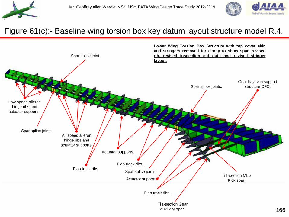
Mr. Geoffrey Allen Wardle. MSc. MSc. FATA Wing Design Trade Study 2012-2019
166
Figure 61(c):- Baseline wing torsion box key datum layout structure model R.4.
Spar splice joints.
Low speed aileron
hinge ribs and
actuator supports.
Spar splice joints.
All speed aileron
hinge ribs and
actuator supports.
Lower Wing Torsion Box Structure with top cover skin
and stringers removed for clarity to show spar, revised
rib, revised inspection cut outs and revised stringer
layout.
Flap track ribs.
Spar splice joint.
Spar splice joints.
Actuator supports.
Flap track ribs.
Ti I-section Gear
auxiliary spar.
Gear bay skin support
structure CFC.
Flap track ribs.
Actuator support. Ti I-section MLG
Kick spar.

Mr. Geoffrey Allen Wardle. MSc. MSc. FATA Wing Design Trade Study 2012-2019
(1):- Metallic ‘I’- beam also applies to
CFRP „I’- section (back to back „C‟
sections).
(2):- Metallic „C‟- section. (3):- CFRP „C‟- section.
Datum plane / surface
In middle of web.
Datum plane / surface
On tool face of web.
Datum plane / surface
On tool face of web.
167
Figure 62:- Key datum's in the layout structure models.
Key datum models show datum positions upon which actual detailed structure will be located when
sized this slide is intended for non / new designers and shows what the model datum‟s represent.

Mr. Geoffrey Allen Wardle. MSc. MSc. FATA Wing Design Trade Study 2012-2019
The wing carry through box layout is shown in figures 63(a), (b), and (c). The following structural
layout has been used:-
Spars:- CFRP monolithic laminate C section with co-bonded web stiffeners (shown in dark
green):
Skins:- CFRP monolithic laminate (shown in green), with 11 top and 11 bottom spanwise
tapered flange „I’ section CFRP solid laminate stiffeners with tapered flanges (shown in dark
green) on developed airframe these are PRSEUS stringers:
The seven internal upper and seven lower chordwise Al/Li load beams (dark blue) to which are
attached 56 angled CFC tube struts (shown in light blue) and 21 vertical CFC tube struts
(shown in orange), The Tube Struts are produced from unidirectional tape automated cross-ply
wound around a foam core, and subsequently is autoclave cured, with Ti alloy embedded
fittings:
The root ribs are currently Al/Li alloy (shown in dark blue), but there is the option to change this
to CFC for the evolved FATA wing depending on further structural analysis:
The seven over wing floor beams are „I’ section CFRP solid laminate which are co-bonded to
the top WCTB and MLGB cover skins, and have splice attachments at each end, also shown in
figure 63 is the port / starboard Al/Li trap panel.
The Wing Carry Trough Box to Fuselage attachments which are Ti alloy machining's attached
to the Root Ribs and leading /trailing edge Spars and to the CFC Fuselage frames:
Keel Beam is a CFC box beam made by RTM, a secondary support keel runs through the
MLGB and supports the APU fuel line and bracketing.
168
Structural layout of baseline aircraft wing carry through box initial sizing.

Mr. Geoffrey Allen Wardle. MSc. MSc. FATA Wing Design Trade Study 2012-2019
169
Figure 63(a):- My FATA baseline wing carry through box full structural model R.6.
Titanium alloy Root Rib to Fuselage Interface
beam attachments (7-off Port /7-off Stbd).
I section Carbon Fibre Epoxy Composite Over-wing
Floor beams (7-off WCTB and 7-off MLGB)
WCTB top CFC Cover Skin. MLGB CFC Cover Skin.
Main Landing Gear Bay
Main Landing Gear Bay
pressure bulkhead Al/Li.
Cargo Bay closure bulkhead Al/Li.
Trap panels Port and Starboard Al/Li. Port / Stbd Al Li Root ribs.
WCTB tank closure
seal caps Ti alloy.
UP
FWD
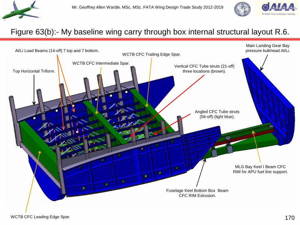
Mr. Geoffrey Allen Wardle. MSc. MSc. FATA Wing Design Trade Study 2012-2019
170
Figure 63(b):- My baseline wing carry through box internal structural layout R.6.
Al/Li Load Beams (14-off) 7 top and 7 bottom.
WCTB CFC Leading Edge Spar.
WCTB CFC Intermediate Spar.
WCTB CFC Trailing Edge Spar.
Top Horizontal Triform.
Vertical CFC Tube struts (21-off)
three locations (brown).
Angled CFC Tube struts
(56-off) (light blue).
MLG Bay Keel I Beam CFC
RIM for APU fuel line support.
Fuselage Keel Bottom Box Beam
CFC RIM Extrusion.
Main Landing Gear Bay
pressure bulkhead Al/Li.

Mr. Geoffrey Allen Wardle. MSc. MSc. FATA Wing Design Trade Study 2012-2019
171
Figure 63(c):- My baseline wing carry through box structural layout R.6.
WCTB CFC Cover co-bonded Skin stiffeners
(22off) 11 on top skin and 11on bottom skin.
MLGB CFC Cover Skin.
WCTB top CFC Cover Skin.
WCTB Bottom CFC Cover Skin.
Bottom Horizontal Triforms.
Cargo Bay trailing edge spar
closure bulkhead Al/Li.
MLG Bay Keel I Beam CFC RIM
for APU fuel line support.
APU fuel line support brackets.
Main Landing Gear Bay
pressure bulkhead Al/Li.
Fuselage Keel Bottom Box Beam
CFC RIM Extrusion.
APU Fuel line.
Mr. Geoffrey Allen Wardle. MSc. MSc. FATA Wing Design Trade Study 2012-2019
The careful arrangement of the wing fuel tank layout (see figure 64(a) and (b) for the initial FATA
baseline wing), from the initial design stages of a commercial aircraft can result in a lighter
structural weight through bending moment relief. The fuel management system is an important
consideration in the structural design of an aircraft, and in addition to the wing tankage the wing
carry through box is also usually a fuel tank.
The way in which the tank fuel tank layout and fuel management in commercial aircraft wings
influences wing bending moment relief is shown by the three cases considered in figure 64(c)
below, i.e. the weight of fuel in the tanks acts down at its centre of gravity (c.g.), thus creating a
downward bending moment which is counter to the lifting upwards bending moment at the root, and
these downwards bending moments are subtracted from the root lift bending moment to obtain the
final root bending moment.
Case A (figure 64(c)):- In this case there are two wing fuel tanks, and by feeding first from the
inboard tank and subsequently from the outboard tank, a fuel weight wing bending moment
relief corresponding to track A is obtained:
Case B (figure 64(c)):- In this case there are also two wing fuel tanks however the inboard
tank is much longer than the inboard tank in case A. Therefore its c.g. remains further
outboard and the fuel weight wing bending moment relief corresponding to track B is obtained:
Case C (figure 64(c)):- In this case there are three wing fuel tanks and by feeding first from the
root tank, next from the mid wing tank, and finally the outboard tank, a wing bending moment
relief corresponding to track C is obtained, which is of the highest magnitude. This latter case
has been selected for the FATA baseline wing box. 172
Wing fuel tank layout effect on bending moment relief.

Mr. Geoffrey Allen Wardle. MSc. MSc. FATA Wing Design Trade Study 2012-2019
173
Main inboard fuel tank
Main mid wing fuel tank.
Outboard reserve fuel tank, and surge and tip vent tanks.
Main fuel tanks are shown with nominal off set for skin
thickness (light blue, and pink) the initial estimated
total maximum capacity of all tanks is 95,500lts
(21,007 Imperial gallons) estimated from volume
envelope.
Figure 64(a):- My baseline FATA wing torsion box initial fuel tank layout.

Mr. Geoffrey Allen Wardle. MSc. MSc. FATA Wing Design Trade Study 2012-2019
174
Figure 64(b):- My baseline FATA initial wing fuel tank layout overview.
Wing Carry Through
Box fuel tank
Port Mid Wing fuel tank
Stbd Mid Wing fuel tank
Port Inboard Wing fuel tank Port Inboard Wing fuel tank
Port Outboard reserve fuel tank,
and surge and tip vent tanks.
Port Outboard reserve fuel tank,
and surge and tip vent tanks.

Mr. Geoffrey Allen Wardle. MSc. MSc. FATA Wing Design Trade Study 2012-2019
175
Root Tip
CASE (A)
Inboard fuel tank Outboard fuel tank
Root Tip
CASE (B)
Inboard fuel tank Outboard fuel tank
Root Tip
CASE (C)
Inboard fuel tank Mid wing fuel tank
Outboard fuel tank
Tip Root
WIN
G B
EN
DIN
G M
OM
EN
T R
EL
IEF
.
CASE (A)
CASE (B)
CASE (C)
Figure 64(c):- Fuel tank layout for maximum bending moment relief.

Mr. Geoffrey Allen Wardle. MSc. MSc. FATA Wing Design Trade Study 2012-2019
The wing root joint design is one of the most critical areas of the aircraft structure, especially for
fatigue considerations of a long life structure. The joint for the Prime Baseline Wing will be carried
over for the Advanced Baseline Wing and then will be re-evaluated for the Future Concept Wings.
The types of joint available for fixed swept wing large transports are outlined table 7 below, and the
option which has been selected as the design solution has been skin splice joints across the root rib
flanges and splice plates attachments for the spars as shown in figure 66(a) through (c).
Table 7:- Wing Root fixed joints.
176
The wing torsion box to wing carry through box root fitting.
JOINT TYPE. ADVANTAGES. DISADVANTAGES.
Spliced plates. Widely used due to its light weight and
more reliable and inherently fail-safe
nature.
Higher cost, and manufacturing and
fitting issues, the latter of which could
be reduced with cover skin sacrificial
plies.
Tension bolts. Less manufacturing, easy to assemble
and remove and inspect, common on
fighter aircraft
Heavy weight penalty.
Discrete lug fittings with shear
bolts.
As for tension bolts and I have greater
experience with designing this type,
common on fighter aircraft.
Heavy weight penalty.
Combinations of tension bolts / or
lug fittings, and spliced plates
Reliable and inherently fail-safe feature,
and less manufacturing and fitting
issues.
Heavy weight penalty.
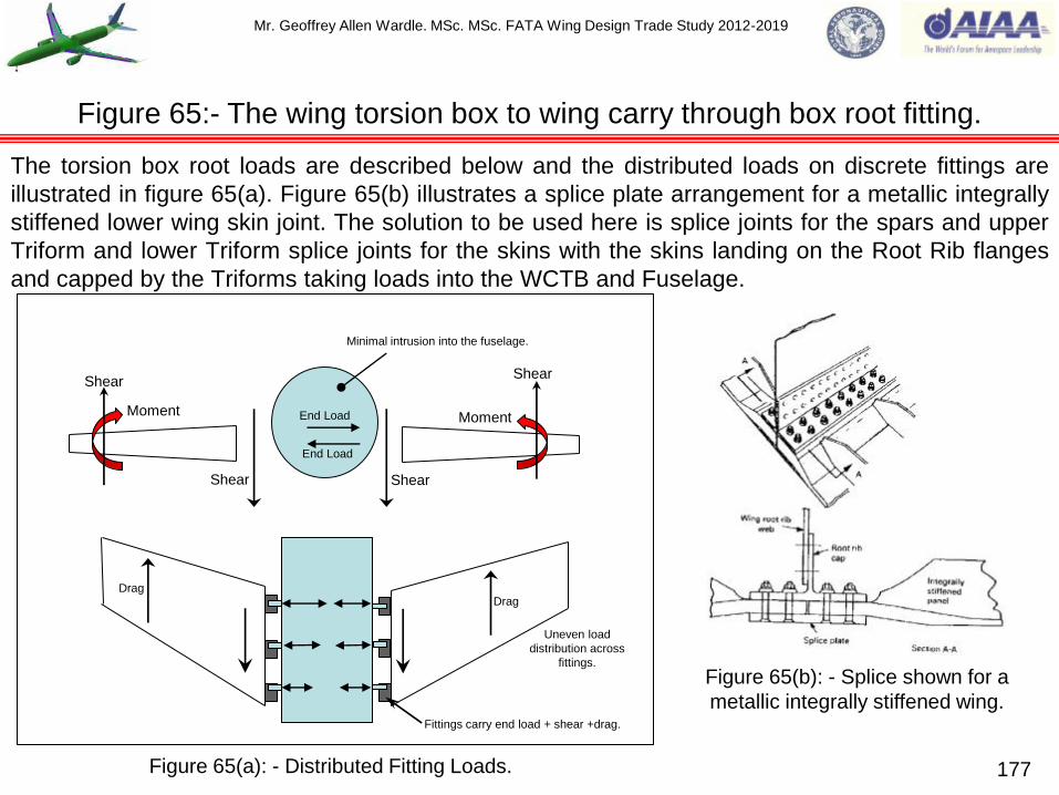
Mr. Geoffrey Allen Wardle. MSc. MSc. FATA Wing Design Trade Study 2012-2019
The torsion box root loads are described below and the distributed loads on discrete fittings are
illustrated in figure 65(a). Figure 65(b) illustrates a splice plate arrangement for a metallic integrally
stiffened lower wing skin joint. The solution to be used here is splice joints for the spars and upper
Triform and lower Triform splice joints for the skins with the skins landing on the Root Rib flanges
and capped by the Triforms taking loads into the WCTB and Fuselage.
177
Figure 65:- The wing torsion box to wing carry through box root fitting.
Shear Shear
Shear Shear
Moment Moment End Load
End Load
Minimal intrusion into the fuselage.
Drag Drag
Uneven load
distribution across
fittings.
Fittings carry end load + shear +drag.
Figure 65(a): - Distributed Fitting Loads.
Figure 65(b): - Splice shown for a
metallic integrally stiffened wing.

Mr. Geoffrey Allen Wardle. MSc. MSc. FATA Wing Design Trade Study 2012-2019
178
Figure 66(a):- The wing carry through box root rib integration.
Wing Carry Through Box Top Cover
Skin (floor beams omitted for clarity).
Wing Torsion Box Cover
Skin Sections Spliced to
Root Rib by Triforms.
Top Horizontal Triform.
Bottom Horizontal Triform. IB wing Leading Edge
Spar Spliced to Root Rib.
IB wing Intermediate Spar
Spliced to Root Rib.
IB wing Trailing Edge Spar
Spliced to Root Rib.
Port Root Rib.
Wing Carry Through Box Root Rib to Fuselage Frame attachments
bolted to Root Rib inboard face and to frames.
IN BD
FWD
UP

Mr. Geoffrey Allen Wardle. MSc. MSc. FATA Wing Design Trade Study 2012-2019
Figure 66(b):- Component assembly of the wing root splice (Port and Stbd).
Top Horizontal Triform.
Bottom Horizontal Triform
Port Root Rib.
Port Rib Crown
Sealing Strips.
Wing Carry Through Box
Leading Edge Spar.
Wing Carry Through Box
Intermediate Spar.
Wing Carry Through Box
Trailing Edge Spar.
IB wing Leading Edge
Spar end section.
IB wing Intermediate Spar
end section.
IB wing Trailing Edge Spar
end section.
LE Spar OB
Splice Plate.
LE Spar IB Splice
Bathtub.
IM Spar IB Splice
Bathtub.
IM Spar OB
Splice Bathtub.
TE Spar IB Splice
Bathtub.
TE Spar OB
Splice Plate.
UP
IN BD
179

Mr. Geoffrey Allen Wardle. MSc. MSc. FATA Wing Design Trade Study 2012-2019
180
Figure 66(c):- Component assembly of the wing root splice (Port and Stbd).
Wing Carry Through Box Root Rib
to Fuselage Frame attachments.
Port Rib Crown
Sealing Strips.
Wing Carry Through Box Root Rib
to Fuselage Frame attachments.
IB wing Trailing Edge Spar end section.
TE Spar IB
Splice Plate.
TE Spar OB
Splice Plate.
Top Horizontal Triform lands on both cover skins and bolts through rib flange and crown.
Bottom Horizontal Triform lands on
both skins and bolts through flange.
UP
OUT BD
Port Root Rib.

Mr. Geoffrey Allen Wardle. MSc. MSc. FATA Wing Design Trade Study 2012-2019
The FATA Fuselage Baseline will use the skin panel structural layout of the Airbus A350 as the
initial structural starting point as the longitudinal joints participate in the fuselages bending
resistance and therefore imparts superior bending strength, and each panel can be optimised for
its specific design case as shown in figure 67(a), these panels being as long as practical to
minimise the number of circumferential joints. Although this is a more complex manufacturing
option than the Boeing 787 barrel option which allows a single process to be used throughout, as
shown in figure 67(b). The Airbus system offers greater compatibility with FATA Prime fuselage
PRSEUS stitched stringer manufacturing technology, although the noes and tail are barrel sections
as shown in figure 67(c), figure 67(d) shows initial cabin window sizing.
The FATA Fuselage Baseline frame stations and build joints are shown in figure 68(a):- Section
11/12 to Section 13/14 joint is at Frame 25: Section 13/14 to Section 15 joint is at Frame 52:
Section 15 to Section 16/18 is at Frame 91: Section 16/18 to Section 19 join is at Frame 118: and
the Section 19 to Section 19.1 joint is at Frame 135. The build joint philosophy selected for the
FATA Fuselage Baseline was the Airbus style lap joint with a splice strip located on frames, as
shown in figure 68(c). This was adopted in preference to the Boeing butt joint with splice strap
located between frames as shown in figure 68(b) which although easier to inspect and maintain but
was not see to enable the direct coupling for high loads that Airbus style lap joint ensures. The
FATA Fuselage Baseline frame design concept adopted the Boeing full depth bolted Z – section
frames mounted over co-bonded hat stringers as shown in figure 68(d), this offered lower
complexity and weight over the Airbus clip based philosophy, more closely resembling the FATA
Fuselage Prime build for analysis, with full depth frames. Table 8 gives a comparison of frame and
stringer types and pitches from which the FATA baseline values were derived.
181
Section 8:- The design and structural layout of the FATA fuselage.

Mr. Geoffrey Allen Wardle. MSc. MSc. FATA Wing Design Trade Study 2012-2019
Figure 67(a):- Design philosophies for composite fuselages ( A350 XWB).
182
A350 Design philosophy:- In order to reduce the operating costs and
environmental impact through reduced fuel burn the airbus A350 adopted the use
of a four composite panel layout for the fuselage skins in the areas shown above.
The key attributes of this layout:-
The skin panels are as long as possible to reduce the number of
circumferential joints:
The longitudinal joints participate in the fuselage resistance to bending hence
increasing bending strength:
Each panel can be optimised for its design case:
Significant weight reductions can be achieved by this design philosophy.
13m 20m 14m
Side panels.
Top panel.
Keel panel.
Port Side panel.

Mr. Geoffrey Allen Wardle. MSc. MSc. FATA Wing Design Trade Study 2012-2019
Figure 67(b):- Design philosophies for composite fuselages ( B-787).
Contoured section. Constant section. Nose section.
Section 48. Section 47. Section 46. Section 44 / 45. Section 43. Section 41.
Fwd body joint. Aft body joint. Centre section
joints.
Aft section joint.
Boeing 787 Design philosophy:- Multiple filament wound barrel sections with major circumferential
splice joints between sections 41 to 43, and 46 to 47. These barrel sections allow a single
manufacturing process to be applied to constant, contoured, and nose sections of the fuselage.
Resitting hoop stresses better than metallics, this allows higher cabin pressures, and larger
windows. 183

Mr. Geoffrey Allen Wardle. MSc. MSc. FATA Wing Design Trade Study 2012-2019
Figure 67(c):- FATA Fuselage design showing frame stations and build joints.
C25 C52
Section 11/12
C91
Section 13/14
C118 C135
Section 15 Section 16/18 Section 19
Section 19.1
FWD Fuselage Centre Fuselage AFT Fuselage
Ground Line
Radome.
Nose Landing Gear.
Frame 20 FWD
Pressure Bulkhead
(*Flat design).
Frame 20 Fwd Pressure Bulkhead being of Flat
design, reacts the pressure loads in bending
and will be machined from with a grid of vertical
and horizontal support beams.
FWD Body Mate Joint.
FWD Centre Body Mate Joint.
Wing Carry
Through Box.
AFT Centre Body Mate Joint.
Main Landing Gear.
Aft Body Mate Joint.
Frame 124 AFT Pressure Bulkhead
(*Curved Membrane design).
Frame 124 Aft Pressure Bulkhead being of Curved Membrane
design, reacts the pressure loads in tension and will have radial
and annular crack stoppers. These are lighter than the flat design,
and provisionally a stitched CFC membrane similar to the A380 aft
bulkhead is proposed.
CFC Barrel
section
CFC Barrel
section
4 CFC Panel
section
4 CFC Panel
section 4 CFC Panel
section
184

Mr. Geoffrey Allen Wardle. MSc. MSc. FATA Wing Design Trade Study 2012-2019
Figure 67(d):- FATA Fuselage cabin window showing sizing and spacing.
540mm
508mm
305mm
Proposed cabin window size is 508mm high
by 305mm wide viewing area, with a frame of
51mm. The proposed separation is 540mm
and the fuselage skin thickness in the window
band will increase to 4.25mm (based on initial
calculations).
51mm
51mm
185

Mr. Geoffrey Allen Wardle. MSc. MSc. FATA Wing Design Trade Study 2012-2019
186
Figure 68(a):- FATA Fuselage design showing fuselage build and panel joints.
Fwd CFC Barrel Section
(B787 example).
Aft CFC Barrel Section
(A350 example).
Section 15 CFC Keel Panel
(A350 example).
Section 13/14 Crown panel:-
Area = 68.051m²: Length = 12.792m
Section 15 Crown panel:-
Area = 110.074m²: Length = 20.645m
Section 16/18 Crown panel:-
Area = 74.569m²: Length = 14.391m
Port Section 13/14 Side panel:-
Area = 39.176m²: Length = 12.792m
Port Section 15 Side panel:-
Area = 63.635m²: Length = 20.645m
Port Section 16/18 Side panel:-
Area = 47.865m²: Length = 14.391m
Section 13/14 Keel panel:-
Area = 87.734m²: Length = 12.792m
Section 15 Keel panel:-
Area = 92.423m²: Length = 20.645m
Section 16/18 Keel panel:-
Area = 94.923m²: Length = 14.391m
Analysis will be of Section 15 Panels initially. (*Note Port and Stbd side panel dimensions are identical).

Mr. Geoffrey Allen Wardle. MSc. MSc. FATA Wing Design Trade Study 2012-2019
187
Figure 68(b)(c):- FATA Fuselage baseline build joint concept options (reference:-20).
MID SECTION SKIN
FWD SECTION SKIN
SPLICE STRAP
STRINGER
SPLICE ANGLE
SPLICE FILLER
SPLICE C-CHANNEL
Figure 68(b):- Example Butt-Joint with splice
strap located between frames, therefore this
type of build joint can be easily inspected and
maintained.
PANEL
STRINGER
BUTT-STRAP
DOUBLER
STRINGER COUPLING (U-SECTION)
FRAME CLIP WITH STABILIZER
ON STRINGER COUPLING
FRAME CLIP ON BUTT-STRAP
Z- CROSS SECTION FRAME
Figure 68(c):- Example Lap-Joint with splice strap
located on frames, enables direct coupling for high
loads but is more of a challenge to inspect.
Fwd Fuse Mid Fuse

Mr. Geoffrey Allen Wardle. MSc. MSc. FATA Wing Design Trade Study 2012-2019
188
Ω-Stringer Co-Bonded to Skin.
Clip PPS Thermoplastic Matrix composite with quasi-isotopic layup
Frame CFRP prepreg.
120mm
Z- Frame lay up [30º/90º/-30º]
with 0º reinforcement.
80mm
Airbus A350 Co-Bonded CFC Ω-Stringers. Boeing 787 Co-cured CFC Hat-Stringers.
Figure 68(d):- FATA Fuselage baseline frame / stringer concept options (reference:- 20).
Airbus A350 Bolted Z- Frame assembly. Boeing 787 Bolted Z-Frame assembly.
Mr. Geoffrey Allen Wardle. MSc. MSc. FATA Wing Design Trade Study 2012-2019
Considering the actual lay out of the FATA fuselage baseline structure it is a combination of both
Boeing and Airbus philosophies as described above.
In the case of the Airbus A350 all of the fuselage panels (except the cockpit cabin see figures 2 and
66(a)) are CFC as are stringers, window frames, clips, and doors, with hybrid door frames
structures consisting of CFC and titanium alloy. Depending on the location on the fuselage the
stringers are either Ω (shown in figure 68(d) note extended flanges for frame clip attachment) or T
profile and these are produced separately to the skin panels, and subsequently co-bonded on to the
panels. As shown in figure 68(d) the frames are attached by a mixture of thermoplastic clips and
special fasteners and are not bonded to the stringers or skin panels. Based on the difference in
fuselage length between the A350-900 XWB and the A350-1000 XWB fuselages which is 7m and
the reported difference in frame number of 11 frames the frame pitch can be estimated as 635mm.
Also the CFC window frames are of L – section profile but have the same strength as the heavier
traditional metal T - section frames (reference 20). From released photographs and presentations
from Airbus (reference 8) the Ω-section stringer pitch is estimated at ~ 230mm .
The Boeing 787 series are 50% CFC by airframe weight figure 2 shows the structural breakdown,
as with the A350 the 787 fuselage has Titanium alloy / CFC hybrid door frames as shown in figure
30(b). The construction modules of the fuselage are complete barrel sections as shown in figures
67(b) and 68(d), and reportedly (reference 20) each barrel section contains 80 hat /Ω-section
stringers, where the constant section is 5.46m (Airbus data) so the stringer pitch would be
~214mm. The average frame pitch on the B787 based on public data is between 574mm and
610mm and the latter figure is taken as the most representative.
189
The design and structural layout of the FATA fuselage (continued).

Mr. Geoffrey Allen Wardle. MSc. MSc. FATA Wing Design Trade Study 2012-2019
190
Table 8:- Comparison of FATA Fuselage frame / stringer layout with current aircraft.
Aircraft
type.
Fuselage
diameter (m)
Skin
material
Frame
material
Frame
profile
Frame
pitch (mm)
Stringer
material
Stringer
profile
Stringer
pitch (mm)
A320 3.96 Aluminium
alloy Aluminium Z 533 Aluminium Z ~150
A330 /
A340 5.64
Aluminium
alloy Aluminium Z 533 Aluminium Z ~220
A350 5.96 Composite Composite Z, L 635 Composite Ω, T ~230
A380 Width 7.14
Height 8.47 Aluminium
Glare Aluminium J 635 Aluminium Z ~210
B737 3.76 Aluminium
alloy Aluminium Z 508 Aluminium Ω 152-178
B747 6.40 Aluminium
alloy Aluminium Z, C 508 Aluminium Ω, Z 203-254
B777 6.20 Aluminium
alloy Aluminium Z 508 Aluminium Z ~230
B787 5.46 Composite Composite Z 610 Composite Ω ~214
FATA
Baseline 5.99 Composite Composite Z 533 Composite Ω 250

Mr. Geoffrey Allen Wardle. MSc. MSc. FATA Wing Design Trade Study 2012-2019
Based on the historical data in table 7 the FATA fuselage structural layout, for analysis using
AeroDYNAMIC™ and following data was used:-
Materials:- By weight, 50% of the latest large commercial transports are CFC namely the A350 and
B787 series, and the fuselage structure is predominantly CFC skin, stringers, and frames, with
Titanium / CFC hybrid door frames. Previous Airbus and Boeing CS-25 fuselage structures have
been metallic comprising of aluminium skins, frames, and stringers. The materials selected for the
FATA baseline fuselage was Cytec industries unidirectional tape X840 Z60 12K, and plain weave
fabric X840 Z60 PW, for skin, frames, and stringers and the provisional thickness and ply layups
are shown in Tables 8(a) through 8(c) the initial skin thickness was 2.9mm.
Geometry:- Frame cross-sections have generally been Z-section or C-section with a height of 85 -
100mm, with a thickness of 2 - 3mm, and a flange width of 25mm:
Stringers have been Z-section with a height of 30mm, with a thickness of 2mm, and a flange width
of approximately 15mm:
CFC Omega - profile stringers (current designs) have a height of 25 – 35mm, a thickness of 1.5 –
2.0mm, and a head width of 25mm and a flange width of 100 – 130mm:
Skin thicknesses dependant on location is reported to be between 1.0mm and 2.6mm thick.
Frame pitch from table 7 ranges 475.2 mm to 533.4mm with some extending this to 610mm to
635mm. A frame pitch of 533mm was selected FATA baseline fuselage although conservative this
was for direct comparison with the FATA PRSEUS Prime fuselage.
Stringer pitch ranges from 150mm to 254mm. A stringer pitch of 250mm was used for FATA. The
structural ply lay up tables for these components are given in table 9(a) through (c).
191
The design and structural layout of the FATA fuselage (continued).

Mr. Geoffrey Allen Wardle. MSc. MSc. FATA Wing Design Trade Study 2012-2019
Structural Ply No Only. Material Nominal ply thickness
(mm) Ply orientation
1 Fabric 0.25 0º/90º
2 UD 0.15 0º
3 UD 0.15 45º
4 UD 0.15 90º
5 UD 0.15 135º
6 UD 0.15 0º
7 UD 0.15 45º
8 UD 0.15 90º
9 UD 0.15 135º
10 UD 0.15 135º
11 UD 0.15 90º
12 UD 0.15 45º
13 UD 0.15 0º
14 UD 0.15 135º
15 UD 0.15 90º
16 UD 0.15 45º
17 UD 0.15 0º
18 Fabric 0.25 0º/90º
192
Table 9(a):- Initial proposed FATA Fuselage 2.9mm thick skin ply stacking sequence.
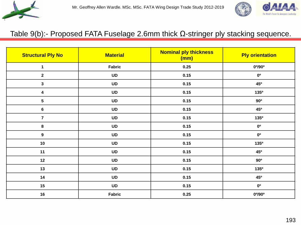
Mr. Geoffrey Allen Wardle. MSc. MSc. FATA Wing Design Trade Study 2012-2019
193
Table 9(b):- Proposed FATA Fuselage 2.6mm thick Ω-stringer ply stacking sequence.
Structural Ply No Material Nominal ply thickness
(mm) Ply orientation
1 Fabric 0.25 0º/90º
2 UD 0.15 0º
3 UD 0.15 45º
4 UD 0.15 135º
5 UD 0.15 90º
6 UD 0.15 45º
7 UD 0.15 135º
8 UD 0.15 0º
9 UD 0.15 0º
10 UD 0.15 135º
11 UD 0.15 45º
12 UD 0.15 90º
13 UD 0.15 135º
14 UD 0.15 45º
15 UD 0.15 0º
16 Fabric 0.25 0º/90º

Mr. Geoffrey Allen Wardle. MSc. MSc. FATA Wing Design Trade Study 2012-2019
194
Table 9(c):- Proposed FATA Fuselage 3mm thick Z-frame ply stacking sequence.
Structural Ply No Material Nominal ply thickness
(mm) Ply orientation
1 Fabric 0.25 ±45º
2 Fabric 0.25 0º/90º
3 Fabric 0.25 ±45º
4 Fabric 0.25 0º/90º
5 Fabric 0.25 ±45º
6 Fabric 0.25 0º/90º
7 Fabric 0.25 0º/90º
8 Fabric 0.25 ±45º
9 Fabric 0.25 0º/90º
10 Fabric 0.25 ±45º
11 Fabric 0.25 0º/90º
12 Fabric 0.25 ±45º

Mr. Geoffrey Allen Wardle. MSc. MSc. FATA Wing Design Trade Study 2012-2019
FATA Baseline Vertical tail design.
The vertical tail presents a set of design issues which are different from those of the wing, or
horizontal tail and theses are be itemised below:-
a) It is not unusual for the vertical tail of a large transport to be integrally attached to (but still
removable from) the rear fuselage, the leading and trailing edge spars of the vertical tail being
attached to dedicated fuselage frames. A root integration plate is built into the vertical tail to
coincide with the upper surface of the fuselage and is used to transmit the vertical tail root skin
shear loads directly into the fuselage skin, this is the case with the Boeing 787 and 777 CFC
vertical tails which use a tension fitting plate to interface with the fuselage with attachment to
this plate at the VT torsion box leading and trailing edge spars. Vertical tail span-wise bending
results in a fuselage torsion. In some cases it is logical to incline the rear spar bulkhead to
continue the line of the rear spar of the vertical tail torsion box, as this is usually at the end of
the fuselage well aft of the rear pressure bulkhead, although no current airliner produced by
either Airbus or Boeing has adopted this layout. All of the current large Airbus and Boeing
passenger aircraft, based on published data from literature surveys and examination of aircraft
cutaways attaching the rear spar to perpendicular frames. The front spar and any intermediate
attachments to frames are also made to perpendicular frame stations within the aft fuselage
Section 19, with the transition being made at the Vertical Tail root rib or integration plate in the
case of the B-777 , and B-787, shown in figure 69(a)ii The structural layout is generally the
same format as the wing with front and rear spars and ribs forming the vertical tail torsion box,
with additional rudder hinge ribs and auxiliary front spar to support de-icing equipment and
other systems in the vertical tail leading edge fairing.
195
Section 9:- The design and structural layout of FATA empennage.

Mr. Geoffrey Allen Wardle. MSc. MSc. FATA Wing Design Trade Study 2012-2019
196
Figure 69(a):- FATA Vertical tail showing fuselage attachment design philosophy.
Figure 69(a)i:- Airbus A350 XWB Vertical tail to
fuselage attachment philosophy i.e. leading edge and
trailing edge star attachment lugs (Flight International
and Airbus gallery). Rudder is CFC and Nomex
honeycomb skins with aluminium ribs. Figure 69(a)ii:- Boeing 777 and 787 Vertical tail to fuselage
attachment philosophy i.e. Tension fixtures and integration
plate (Flight International and Boeing gallery). Rubber is CFC
and Nomex honeycomb skins with aluminium ribs.

Mr. Geoffrey Allen Wardle. MSc. MSc. FATA Wing Design Trade Study 2012-2019
b) Alternatively the vertical tail is designed to be readily detached as in the case of fighter aircraft
and modern large transports, in this case attachment is through a system of lugs attached to
the leading edge and trailing edge spars as shown for the Airbus A350 in figure 69(a)i. The
vertical attachment lugs are arranged in both lateral and fore and aft directions so that in
addition to vertical loads they react side and drag loads. The normal layout being that the lugs
attached to the leading edge spar arranged laterally and react the vertical and drag loads, and
the lugs attached to the trailing edge spar are arranged in the fore and aft direction and react
the vertical and side loads. This lug attachment philosophy was selected for the FATA vertical
tail which is attached at the leading edge and trailing edge spars with lateral and fore and aft
lugs to perpendicular fuselage frames.
c) The rudder attachment to the vertical tail is invariably supported by a number of discrete hinges
and number and location of these hinges depends on the length and weight of the rudder, and
the other major points to consider in rudder attachment design are as follows:-
i. The bending distortion of the control surface relative to the fixed vertical tail must be limited
so that the nose of the control does not foul the fixed shroud:
ii. The control hinge loads and the resulting shear forces and bending moments should be
equalized as far as possible:
iii. Structural failure of a single hinge should be tolerated unless each hinge is of fail-safe
design and can tolerate cracking in one load path.
197
The design and structural layout of FATA empennage (continued).

Mr. Geoffrey Allen Wardle. MSc. MSc. FATA Wing Design Trade Study 2012-2019
198
Figure 69(b):- FATA Vertical tail showing internal structural layout key datum positions.
Fwd Attachment Frame interface:- two
lateral lugs the Leading Edge spar root.
Aft Fuselage
barrel section.
Mid Attachment Frame interface:- two Fore
and Aft lugs on the Mid spar root.
Aft Attachment Frame interface:- two Fore
and Aft lugs on the Trailing Edge spar root.
Triplex rudder
EHA actuators.
CFC Stringers.
CFC Leading Edge Spar.
CFC Vertical Tail Leading
Edge box with Al/Li Ribs.
CFC Mid (Intermediate) Spar.
CFC Trailing Edge Spar.
Al/Li alloy all Ribs.
Rudder CFC Honeycomb
skins with Al/Li ribs .
Figure 69(b)i:- VT / Frame interface.
FWD
Figure 69(b)ii:- VT internal layout
Port skin and stringers removed.
UP
CFC Skins. Vertical Tail Pf Area = 35.36m²
Rudder Pf Area = 15.00m²

Mr. Geoffrey Allen Wardle. MSc. MSc. FATA Wing Design Trade Study 2012-2019
These points suggest the use of a relatively large number of discrete hinges but there are
issues associated with this solution. There is the obvious issues of high assembly complexity
and maintenance, and hinge alignment difficulties. Additionally the loads likely to be induced in
the rudder by the distortion under load of the vertical tail to which it is attached may be
significant. These problems do not arise if only two hinge points are used as any span-wise
distortion or misalignment can be accommodated by designing one of the hinges so that it can
rotate about a vertical axis a so called „floating‟ hinge. When more than two hinges are used
this „floating‟ hinge concept cannot fully overcome the problems. However it is possible to
design the control surface so that it is flexible in bending and indeed the more hinges there are
the easier this is to accomplish. One hinge must always be capable of reacting side loads in the
plane of the control surface, the hinges being supported near to the aft extremities of the
vertical tail ribs. For the initial internal structural layout concept the FATA Baseline Vertical Tail
the rudder attachment layout of the Airbus A330 was used as a starting point for analysis using
AeroDYNAMIC™ of loads and detailed structural analysis.
FATA Baseline Horizontal tail design.
When the horizontal tail is constructed as a single component across the centreline of the aircraft
the basic structural requirements are the very similar to the wing see above. Therefore to address
this the concept structure was designed as two spar multi rib torsion box, with two actuator
positions for the elevator on the Port and Stbd Horizontal Tail Planes figure 70(b), this is similar to
the Airbus A350 WXB, and A330. The Boeing 787 takes a different approach with the horizontal tail
torsion box being multi spar construction. The all moving FATA horizontal tail is attached to the
fuselage by the fwd Screw Jack actuator fitting and aft pivot lugs figure 70(a).
199
The design and structural layout of FATA empennage (continued).

Mr. Geoffrey Allen Wardle. MSc. MSc. FATA Wing Design Trade Study 2012-2019
200
Figure 70(a):- FATA Horizontal tail showing internal and interface design philosophy.
Figure 70(a):- Airbus A350 XWB Horizontal tail to fuselage attachment philosophy i.e. stiffened centre box is attached to
the screw jack actuator at the front, and at trailing edge is attachment with two pivot outer lugs. The same basic layout is
used by Boeing (Flight International and Airbus gallery). Elevators are constructed of CFC skinned Nomex honeycomb
skin panels with aluminium ribs, and mesh instead of electrical bonding straps.
Port Lug Stbd Lug
HT Composite leading edge spars.

Mr. Geoffrey Allen Wardle. MSc. MSc. FATA Wing Design Trade Study 2012-2019
201
Figure 70(b):- FATA Horizontal tail showing internal structure key datum positions.
CFC Leading Edge Spar.
CFC Trailing Edge Spar.
View on arrow „B‟ of Jack Screw
actuator attachment lug.
A
CFC Torsion Box Skins.
View on arrow „A‟ of Port and
Stbd HT Pivot lugs.
B
CFC Horizontal Tail Leading
Edge box with Al/Li Ribs.
CFC Horizontal Tail
Leading Edge box
with Al/Li Ribs.
Al/Li alloy all Ribs.
Out-BD Elevator
EHA actuator.
In-BD Elevator
EHA actuator.
Elevators CFC Honeycomb
skins with Al/Li ribs.
CFC Stringers.
Four-part Hard Back.
Stiffened CFC Centre Box.
FWD
UP
PORT
Port or Stbd Horizontal Tail Pf Area = 23.49m²
Port or Stbd Elevator Pf Area = 10.18m²

Mr. Geoffrey Allen Wardle. MSc. MSc. FATA Wing Design Trade Study 2012-2019
Type-2 assembly:- Current metallic aircraft assembly is a Type-2 process in that it requires precise
fixtures and jigs to support the metallic components in build, and the majority of these jigs and
fixtures are specific to the airframe model and configuration, therefore the manufacture has to rely
on a relatively long production run to for the tooling to be economic. The reason for this, is that it
would be prohibitively expensive to attempt to make large and temperature sensitive – sensitive
structures to tolerances as small as 3x10 on a relative basis, and such fine tolerances are
required to reduce locked in stresses. The resultant structures are relatively stiff compared to the
component parts so small deformations can usually be eliminated by bending the structure,
however this induces local stresses which detract from the flight load carrying capabilities of the
assembly and therefore should be avoided where ever possible.
Boeing seeks to avoid such stresses by building structural components with multiple slip joints by
ensuring that there is empty space at maximum material condition in many joint conditions. These
spaces are filled by peel-apart metallic shims until the gap is small enough to be safely pulled
together with fasteners.
Airbus seeks to avoid such stresses by making their structural components through high precision
5 axis NC machining (see career presentation), which produces a very accurate part that only
requires occasional application of liquid shim (this methodology is also used in UK military aircraft I
have worked on).
Type-1 assembly:- Bridges and skyscrapers are classed as Type-1 assembles as their materials
are thick section and rugged, and they are assembled from hole pattern features, although hole
filling requirements are not as critical as for aircraft and the materials are less temperature
sensitive, and there is not the same need to conserve weight. 202
-4
Section 10:- Airframe structural assembly philosophies.
Mr. Geoffrey Allen Wardle. MSc. MSc. FATA Wing Design Trade Study 2012-2019
Therefore bridges and sky scrapers constitute Type-1 assemblies in that they are assembled by
joining of their component parts rapidly at their features without dedicated single use tooling.
Given the costs and the number of non-added value operations involved in airframe assembly the
direction of assembly research in this design trade study will be focused on reducing the amount of
manual labour and the specificity of the fixtures required to assemble the wing torsion box and wing
carry through box. The weight of the components in theses structures will still need require support
to avoid collapse in assembly, so fixture-like structures will still be necessary but they might not
need to be as accurate or as specific as they are now, lessons learnt from the Mantis UAS field
assembly will be used to modularize these structures into a kit form facilitating autonomous
assembly, of major build units. Three major research activates will be perused in common with
other current research these are:- (1) move towards new composite manufacturing and assembly
methods using preforms and RIM and sacrificial plies: (2) the broad attempt to move aircraft
structures from Type-2 to Type-1 assembly: (3) autonomous assembly.
Activities (1) and (3) are covered in some detail in the latter sections of this research status update,
so here I will briefly cover activity (2).
Develop aircraft structures for Type-1 assembly:- If aircraft parts can be made to net size and
shape with assembly fixtures incorporated in them then they could be tacked together to achieve
the desired final assembly dimensions and relationships just by joining these features (as was
achieved with the Terrasoar light UAS wing / boom assembly). Then they could be given their final
assembly fasteners as before. The savings would arise from the elimination accurate and specific
fixtures.
203
Assembly of baseline aircraft wing torsion box structural members (cont.).
Mr. Geoffrey Allen Wardle. MSc. MSc. FATA Wing Design Trade Study 2012-2019
While progress has been made in this area it is not felt possible to pre-drill every fastener hole as is
done in building and bridge construction. The holes in aircraft construction must be essentially
exactly opposite each other or the fastener cannot fill the hole causing fretting which leads to hole
elongation, corrosion and fatigue, because the fastener will wobble when exposed to oscillating
shear loads normal to its axis rapidly enlarging the hole until to can carry no load at all. The only
current method to achieve many holes that are exactly opposite each other is to match drill on
assembly when the parts are clamped together in their correct relative position. The focus of
attention of current research in this area is therefore on tack fastening to create mates that pass the
dimensional location constraints between the parts, and achieving this would create Type-1 aircraft
assembly. The work I intend to undertake in this area is to identify which critical fastener locations
could become tack fasteners and to look at additional features which could be designed in for a
Lego type build solution.
Figure 71 on the next two slides illustrates proposed join concepts for the rib to leading and trailing
edge spars here there are two possible innovations:- One is the integral cleat shown in figure 71(c)
which would remove the need for additional spar / rib cleating reducing parts count and assembly
time, although the possibility of a resin rich area at the bend must be considered, I have designed
an actual rib based on my key datum model and the current loads drop figures 43 to 47. The other
innovation is the composite post which would be produced from back to back RTM moldings I am in
the process of conducting drape trials and calculations for the flow required to realistically mold
such articles, woven cloth would be used in preference to UD ply to reduce the risk of fibre-wash,
this would then be co-bonded into the Leading edge spar.
204
Assembly of baseline aircraft wing torsion box structural members (cont.).

Mr. Geoffrey Allen Wardle. MSc. MSc. FATA Wing Design Trade Study 2012-2019
205
Figure 71:- Metallic rib build joints selected for assembly of the baseline wing.
Ti Rib post.
Fig 71(a):- Dry Bay Al rib Bathtub nested into CFC Trailing Edge Spar joints.
* Based on 2 countersunk x 1.25” diameter fasteners + 0.06” clearance.
** Based on diameter of Eddie bolt installation tool and footprint of clickbond
nutplate.
Top wing cover skin.
Bottom wing cover skin.
Rear spar.
Bonded anchor nuts.
* 2.5 d
**
Wing rib to spar bathtub.
Fig 71(b):- Rib to Leading Edge Spar post joints.
*Based on 3 x fasteners.
This joint employs a rib attachment post mounted in the spar
for the rib tab to land on which could be bonded or bolted in
place although shown here as a Ti fitting a CFC co-bonded
post is to be studied.
Front spar.
Wing rib to spar tab.
*
2d+1.5mm
4d

Mr. Geoffrey Allen Wardle. MSc. MSc. FATA Wing Design Trade Study 2012-2019
206
Figure 71:- Composite rib build joints selected for assembly of the baseline wing.
Top wing cover skin.
Fig 71(c) CFC Rib to CFC Trailing Edge integral cleat joints.
Integral cleat removes the need for cleated joint reducing parts count
and easing assembly this is a concept for illustrative purposes an
actual rib design will be included in the next update.
Bottom wing cover skin.
Front spar.
Wing rib to spar tab.
CFC Rib post. 3-d 2.5-d
6-d
Fig 71(d) CFC Rib to CFC Leading Edge Spar post joints.
Rib tab attachment bolted to co-bonded RTM integral spar post
joints composed of two back to back filled C sections.
Wing rib to spar integral cleat.
Rear spar.
Bolted through Rear spar web.
4d
3d edge of cleat
Mr. Geoffrey Allen Wardle. MSc. MSc. FATA Wing Design Trade Study 2012-2019
Before proceeding with the conventional baseline design, it is important to consider the
advantages and disadvantages of both bolted and bonded construction methods and the impact
of corrosion on composite assemblies.
The advantages of bolted assembly are:-
1)Reduced surface preparation:
2)Ability to disassemble the structure for repair:
3)Ease of inspection.
The disadvantages of bolted assembly are:-
1)High stress concentrations:
2)Weight penalties incurred by ply build ups, and fasteners:
3)Cost and time in producing the bolt holes, and inspection for delamination's:
4)Assembly time.
Corresponding issues for bonded assembly are set out below.
The advantages of bonded assembly are:-
1)Low stress concentrations:
2)Small weight penalty:
3)Aerodynamically smooth.
207
Composite structural assembly joint design and corrosion.

Mr. Geoffrey Allen Wardle. MSc. MSc. FATA Wing Design Trade Study 2012-2019
Composite structural assembly joint design and corrosion (continued).
The disadvantages of bonded assembly are:-
1) Disassembly, in most cases some part of a bonded structural assembly will need to be bolted
instead of bonded to permit access for repair and inspection. An example is the Typhoon
wing structure where the bottom skin is co-bonded to the structural spars, and top skin is
bolted to the same spars, permitting access from one side:
2) Surface preparation, and bond line inspection for porosity even in co-bonded joints using C-
scan ultrasonic inspection, resulting increased costs and time:
3) Need to design for bolted repair access:
4) Environmental degradation due to water absorption leading to degradation in hot / wet
condition, solvent attack:
5) Need for increased qualification testing effort to establish design allowables.
In the case of the baseline wing configuration both bolted and co bonded construction will be
selected primarily because of the requirement to quickly, inspect, repair, or replace damaged
structural components within a first line servicing environment. In the assembly models bolt
datum positions are shown as points and vectors, as was the practice within BAE Systems MA&I,
and for this level of study only selected detail fastener models will be created.
208

Mr. Geoffrey Allen Wardle. MSc. MSc. FATA Wing Design Trade Study 2012-2019
Co-Curing:- This is generally considered to be the primary joining method for joining
composite components the joint is achieved by the fusion of the resin system where two (or
more) uncured parts are joined together during an autoclave cure cycle. This method minimises
the risk of bondline contamination generally attributed to post curing operations and poor
surface preparation. But can require complex internal conformal tooling for component support.
Co-Bonding:- The joint is achieved by curing an adhesive layer added between a co-cured
laminate and one or more un-cured details. This also requires conformal tooling as shown in
figure 72, and as with co-curing the bond is formed during the autoclave cycle, this method was
used on Eurofighter Typhoon wing spars which were co-bonded to the lower wing cover skins,
and proposed for the F-35B VT lower skin stringers in SWAT trade studies. Care must taken to
ensure the cleanliness of the pre-cured laminate during assembly prior to the bonding process.
Secondary Bonding:- This process involves the joining of two or more pre-cured detail
parts to form an assembly. The process is dependent upon the cleaning of the mating faces
(which will have undergone NDT inspection and machining operations). The variability of a
secondary bonded joint is further compounded where „two part mix paste adhesives‟ are
employed. Generally speaking, this is not a recommended process for use primary structural
applications.
Design considerations for adhesive bonded joints.
209

Mr. Geoffrey Allen Wardle. MSc. MSc. FATA Wing Design Trade Study 2012-2019
UN-CURED „Z‟ & „C‟
SPAR ELEMENTS
„FILM‟ ADHESIVE
(BSL.322)
„CLEAVAGE‟ FILLED WITH
UN-CURED CFC WEDGE
RELEASE AGENT
PRE-CURED
CFC SKINS
UN-CURED „Z‟ & „C‟
SPAR ELEMENTS
CONFORMABLE TOOLING SHOWN AS:-
Figure 72:- Co-Bonded composite spar manufacture.
210

Mr. Geoffrey Allen Wardle. MSc. MSc. FATA Wing Design Trade Study 2012-2019
Composite bolted joint design rules:-
1) Design for bolt bearing mode of failure:
2) Counter sink (CSK) depth should not exceed 2/3 of the laminate thinness if required fill
laminate artificially with syntactic core (if design rules permit e.g. not permitted for USN, or
USMC):
3) Minimum bolt pitch is 4D for sealed structures such as fuel tanks, and 6D for non sealed
structures (where D is the bolt diameter) figure 73:
4) Use only Titanium alloy or stainless steel fasteners to minimise corrosion risk:
5) Use a single row of fasteners for non sealed structures and a double row for sealed
structures such as fuel tanks see figure 74 next slide:
6) Minimum fastener edge distances are:-
3-D in the direction of the principal load path see figure 73:
2.5-D transverse to the principal load path see figure 73:
211
Composite structural assembly joint design and corrosion (continued).
Figure 73:- Fastener edge distances.
2.5xD 3.0xD
4.0 x D

Mr. Geoffrey Allen Wardle. MSc. MSc. FATA Wing Design Trade Study 2012-2019
212
Figure 74:- Corrosion / leek prevention methods for carbon fibre structures.
Prevent moisture ingress:
Prevent electrical contact between CFC and Al alloy:
Anodise, Prime and Paint all Al alloy parts:
Seal in accordance with Project specifications.
Corrosion / leak prevention (fuel tank) example.
Titanium Alloy Fasteners
(NOT cadmium plated)
Dipped prior to assembly.
Al alloy Rib
CFC Spar
Polysulphide
Sealant (PRC)
- FUEL TANK -
- CFC SKIN -
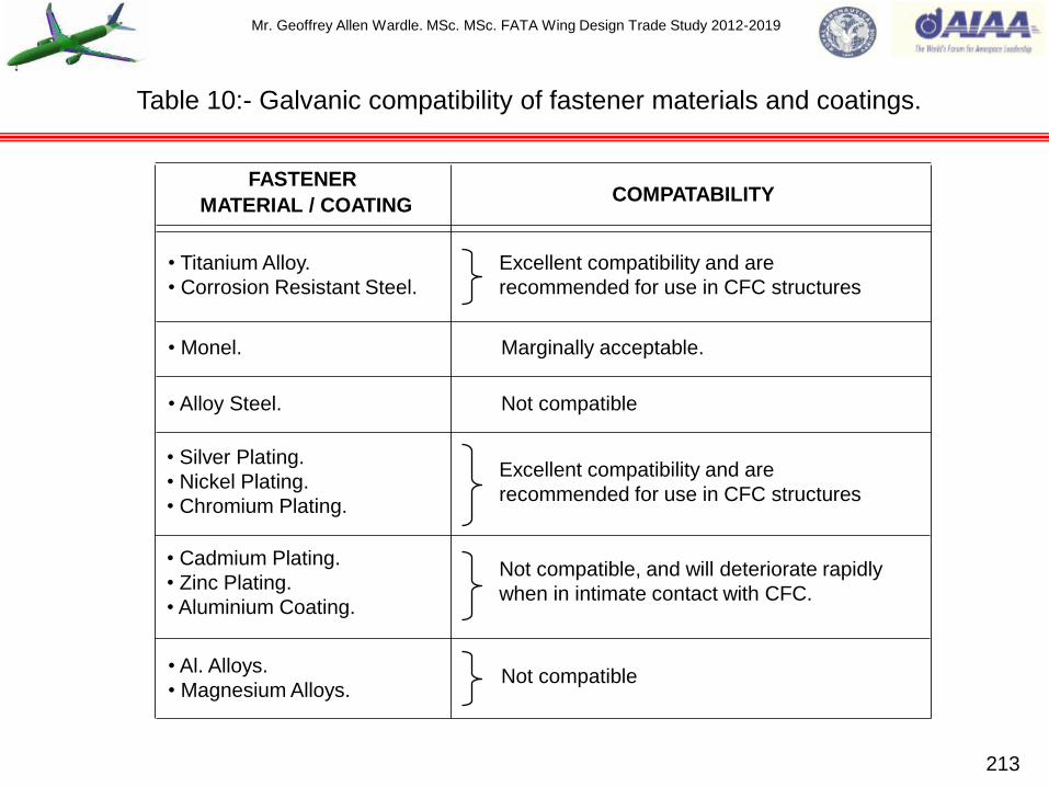
Mr. Geoffrey Allen Wardle. MSc. MSc. FATA Wing Design Trade Study 2012-2019
213
FASTENER
MATERIAL / COATING COMPATABILITY
• Monel. Marginally acceptable.
• Alloy Steel.
• Silver Plating.
• Nickel Plating.
• Chromium Plating.
Excellent compatibility and are
recommended for use in CFC structures
• Cadmium Plating.
• Zinc Plating.
• Aluminium Coating.
Not compatible, and will deteriorate rapidly
when in intimate contact with CFC.
• Titanium Alloy.
• Corrosion Resistant Steel.
Excellent compatibility and are
recommended for use in CFC structures
• Al. Alloys.
• Magnesium Alloys.
Not compatible
Not compatible
Table 10:- Galvanic compatibility of fastener materials and coatings.
Mr. Geoffrey Allen Wardle. MSc. MSc. FATA Wing Design Trade Study 2012-2019
214
The use of carbon composites in conjunction with metallic materials is a critical design
factor :-
Improper interfacing can cause serious corrosion :
Problem for metals e.g. Fasteners see table 10 above:
This corrosion problem is due to the difference in electrical potential between some of the
materials widely employed in the aircraft industry, and carbon:
When in contact with carbon and in the presence of moisture (electrolyte), anodic materials
will corrode sacrificially (galvanic corrosion).
Corrosion prevention methods:-
1) Prevent moisture ingress:
2) Prevent electrical contact carbon / metal:
3) Anodise aluminium parts:
4) Seal in accordance with project specifications:
5) Protective ply of inert cloth (glass) between contact surfaces extending 1” beyond edge on
metal part, and protective sealant (Polysulphide) „Interfay‟ see figure 75 on next slide.
Corrosion due to the galvanic compatibility of materials and coatings.

Mr. Geoffrey Allen Wardle. MSc. MSc. FATA Wing Design Trade Study 2012-2019
215
Figure 75:- Corrosion prevention methods for carbon fibre structures.
EPOXIDE PRIMER (15 to 25 Microns THICK)*
ANODIC TREATMENT*
Pu. VARNISH or EPOXIDE PAINT FINISH (ONE COAT)*
Al ALLOY COMPONENT
POLYSULPHIDE „INTERFAY‟ SELANT
EPOXIDE PRIMER**
GRP (As required as a „Drill
Breakout‟ material.)**
CARBON FIBRE COMPOSITE
* = Applied over the entire Al component.
** = Applied over the entire CFC
component – or a minimum of 5mm
beyond the contact area.
Mr. Geoffrey Allen Wardle. MSc. MSc. FATA Wing Design Trade Study 2012-2019
216
1) Stress concentrations exert a dominant influence on the magnitude of the allowable design
tensile stresses. Generally, only 20-50% of the basic laminate ultimate tensile strength is
developed in a mechanical joint:
2) Mechanically fastened joints should be designed so that the critical failure mode is in bearing,
rather than shear out or tension, so that catastrophic failure is prevented. To achieve this an
edge distance to fastener diameter ratio (e/D), and a side distance to fastener diameter ratio
(s/D) relatively greater than those for metallic materials is required, (see figure 73 above). At
relatively low e/D and s/D ratios, failure of the joint occurs in shear out at the ends, or in tension
at the net section. Considerable concentration of stress develops at the hole, and the average
stresses at the net section at failure are but a fraction of the basic tensile strength of the
laminate:
3) Multiple rows of fasteners are recommended for unsymmetrical joints, such as shear lap joints,
to minimize bending induced by eccentric loading:
4) Local reinforcement of unsymmetrical joints by arbitrarily increasing laminate thickness is to be
avoided because the resulting eccentricity can give rise to greater bending stress which
negates the increase in material thickness:
5) Since stress concentrations and eccentricity effects cannot be calculated with a consistent
degree of accuracy, it is advisable to verify all critical joint designs by testing of a representative
sample joint.
Composite structural mechanically fastened joint design guidelines.

Mr. Geoffrey Allen Wardle. MSc. MSc. FATA Wing Design Trade Study 2012-2019
217
6) If a laminate is dominated by 0° fibers with few 90° fibers it is most likely to fail by shear out,
unlike metals, in which shear out resistance can be increased by placing the hole further from
the edge, laminates are weakened by fastener holes regardless of distance from the edge.
Reinforcing plies at 90° to the load direction helps prevent both shear out and cleavage failures:
Use larger fastener edge distances than with aluminum design, e.g. e/D >3: Use a minimum of
40% of ± 45° plies (for their influence on bearing stress at failure: Use a minimum of 10% of 90°
plies.
7) Net tension failure is influenced by the tensile strength of the fibers at fastened joints, which is
maximized when the fastener spacing is approximately four times the fastener diameter (see
figure 68 above). Smaller spacing's result in the cutting of too many fibers, while larger
spacing‟s result in bearing failures in which the material is compressed by excessive pressure
caused by a small bearing area: Use minimum fastener spacing as shown in figure 73 with 5D
spacing between parallel rows of fasteners: Pad up to reduce net section stresses.
8) To avoid fastener pull-through from progressive crushing / bearing failure:- Design joint as
critical in bearing: Use pad up: Use a minimum of 40% of ± 45° plies: Use washer under collar
or wide bearing head fasteners: Use tension protruding heads when possible.
9) To avoid shear failure:- Use large diameter fasteners: Use higher shear strength fasteners:
Never use a design in which failure will occur in shear.
Composite structural mechanically fastened joint design guidelines (continued).
Mr. Geoffrey Allen Wardle. MSc. MSc. FATA Wing Design Trade Study 2012-2019
10) Use two row joints when possible, as the low ductility of advanced composite material confines
most of the load transfer to the outer rows of fasteners.
11) The choice of optimum layup pattern for maximized fastener strength is simplified by the
experimentally established fact that quasi – isotropic patterns (0°/±45°/90°), or (0°/45°/90°/-45°)
are close to optimum, in practice this reduces experimental costs and simplifies analysis and
design of most fastened joints.
12) The effects of eccentricities on joints:- if eccentricities exist in a joint, the moment produced
must be resisted by the adjacent structures: eccentrically loaded fasteners patterns may
produce excessive stresses if eccentricity is not considered.
13) Mixed fastener types should not be used, i.e. it is not allowed to use both permanent fasteners
and removable fasteners in combination on the same joint, this is due to the better fit of the
permanent fasteners, which would result in the removable fasteners not picking up their
proportionate share of the load until the permanent fasteners have deflected enough to take up
clearance of the removable fasteners in their holes.
14) Do not use a long string of fasteners in a splice joint, because the end fasteners will load up first
and hence yield early. Therefore use three or four fasteners per side as the upper limit unless a
carefully tapered, thoroughly analyzed splice is used (wherever possible use a double shear
splice).
218
Composite structural mechanically fastened joint design guidelines (continued).

Mr. Geoffrey Allen Wardle. MSc. MSc. FATA Wing Design Trade Study 2012-2019
15) Use tension head fasteners for all applications (because potentially high bearing stress under
the fastener head cause failure). Shear head fasteners may be used in special applications.
16) Where local buildup is required for fastener bearing strength, total layup should be at least 40%
± 45° plies.
17) Installation of fasteners wet with corrosion inhibitor may be required in some cases.
18) Use of large diameter fasteners in thicker composite assemblies (for example to transfer critical
joint loads, fastener diameters should be about equal to the laminate thickness) to avoid peak
bearing stress due to fastener bending. Fastener bending is much more significant for
composites than for metals, because composite are thicker for a given load, and more sensitive
to non-uniform bearing stresses due to brittle failure modes.
19) N.B. the best fastened joints can barely exceed half the strength of unnotched laminate.
20) Peak hoop tension stress around fastener holes is roughly equal to average bearing stress.
21) Fastener bearing strength is sensitive to through - the – thickness clamping force of laminates it
is highest for a 30% / 60% /10% (0º/± 45°/90°) ply lay up stack, and much lower for
50%/40%/10% (0º/± 45°/90°) ply lay up stack.
22) Production tolerance build ups:- proper tolerances should be determined with manufacturing to
minimize the need for shimming: shim allowance should be called out on engineering drawings:
N.B. since production tolerances can easily be exceeded in the thickness tolerance, fastener
grip length can be adversely affected.
219
Composite structural mechanically fastened joint design guidelines (continued).

Mr. Geoffrey Allen Wardle. MSc. MSc. FATA Wing Design Trade Study 2012-2019
Shims are used in airframe production to control structural assembly and to maintain aerodynamic
contour and / or structural alignment. With composite joints the allowable unshimmed gaps are only
¼ as large as those for an similar metallic structural joints. Therefore, the assembly of composites
generally require more extensive use of shims than comparable metal components.
Engineering can reduce both cost and waste by controlling shim usage through design and
specifications. Design can control where to shim: what the shim taper and thickness should be:
what gap to allow: and whether the gap should be shimmed or pulled up with fasteners.
Shim materials currently available are:-
1)Solid shims:- titanium: stainless steel: precured composite laminates: etc.
2)Laminated (or peelable) shims with a laminate thickness of about 0.003” (0.0762mm) ±0.0003”
(0.00762mm)
Laminated titanium shims:
Laminated stainless steel shims:
Laminated Kapton shims.
3)Moldable shim, which is a cast – in – place plastic designed for use in filling mismatches between
metal or composite parts. It can be used at any location to produce custom mating molded surfaces
examples are given in the reference works given in the end of this report.
220
Composite structural mechanically fastened joint design shim guidelines.
Mr. Geoffrey Allen Wardle. MSc. MSc. FATA Wing Design Trade Study 2012-2019
Align fibres to principle load direction:
The lay-up ply orientations must be balanced about the mid-plane (neutral axis) of the laminate,
as so to avoid distortion during cure:
Outer plies shall be mutually perpendicular to improve resistance to barely visible impact
damage:
Overlaps and butting of plies:- (a) U/D, no overlaps, butt joint or up to 2mm gap: (b) Woven
cloth, no gaps or butt joints, 15mm overlap:
No more than 4 plies (0.125mm per ply) of a single orientation in one stack within a laminate:
A maximum of 67% of any one orientation shall exist at any position in the laminate:
4 plies separation of coincident ply joints rule (ply stagger rules):
Changes in the laminate thickness should occur evenly with a taper rate of 1 in 20 in the
principal load direction. This can be reduced to 1 in 10 in the traverse direction:
All ply drop-offs to be internal and interleaved with full plies:
Internal corner radii of channels:- (a) „t‟ < 2.5mm, radius = 2t or 3.0mm whichever is greater: (b)
„t‟ 2.5mm, radius = 5.0mm
While co-curing honeycomb sandwich panels, beware of ply quilting during cure over the core
area, need for core stabilisation and reduced cure pressures.
Minimum skin thickness over honeycomb sandwich panels to prevent moisture ingress to be
respected (typically 1mm for UD and 1.5 for cloth). Use of surface films on thin skin panels such
as Tedlar can be considered.
Composite ply layup guidelines applied to FATA wing based BAE Systems MA&I practice.
221

Mr. Geoffrey Allen Wardle. MSc. MSc. FATA Wing Design Trade Study 2012-2019
In the proceeding slides I have referred to the use of sacrificial plies to ensure build tolerances are
met in composite skin and spar joint assembly. In this section I will give a brief outline of them and
their design requirements which will be applied in the design of composite structure in this project
As discussed above carbon fibre composites are fabricated using individual plies in orientations
defined by engineering to specific thicknesses in order to carry the design loads. Due to parent
material thickness variation for the raw material as well as those introduced as part of the post
layup cure process, the resulting laminate product will have varying thickness. Therefore in order
attain a specific thickness to aid assembly and meet aerodynamic OML mismatch requirements a
procedure has been adopted to predict the amount of variation expected in the structural laminate.
A sufficient amount of sacrificial plies are added to the laminate at the interface location to the
substructure to compensate for the expected variation. Finally, the thickness is machined to the
specific desired thickness without infringing into the structural plies.
In the fabrication of a laminate, a “buffer or waviness layer” is used to isolate the structural plies
from the sacrificial machining as shown in figure 76(a). This buffer or witness ply is designed to
provide a visual indicator to manufacturing of machining through the sacrificial plies and into the
structural plies. The specific buffer layer on the laminate is dependent on the laminate material and
will be issues in project guidelines. Considerations must also be given to laminate thickness
changes i.e. ramped ply-drop areas, and the locating accuracy of ply-drops must be compensated
with sacrificial plies in the footprint of the substructure. The assembly process of mating the skin to
the substructure adds the positioning accuracies of the locating holes to require a designed in gap
at these ply-drop ramps.
222
Composite sacrificial plies for assembly tolerance control.

Mr. Geoffrey Allen Wardle. MSc. MSc. FATA Wing Design Trade Study 2012-2019
223
Figure 76:- Sacrificial ply design to meet assembly requirements.
Skin OML
Figure 76(a):- CFC sacrificial incorporation in ply lay up to meet assembly tolerance.
Substrate finish coating
Machined Shim
Faying Sealant
Machined Sacrificial Plies
Adhesive /Fabric Buffer (Witness) Layer
Laminate finish coating
Structural Plies
Fibermat
OML
Figure 76(b):- CFC laminate thickness constituents to meet assembly tolerance.
Machined Shim
Faying Sealant
Machined Sacrificial Plies
Laminate finish coating
Adhesive /Fabric Buffer (Witness) Layer Structural Plies OML Plies
Substructure OML
Machined Skin IML
Nominal
Laminate
Thickness

Mr. Geoffrey Allen Wardle. MSc. MSc. FATA Wing Design Trade Study 2012-2019
The following design details need to be considered prior to computation of the sacrificial ply
thickness (see figure 76(b)): -
1. Determine the buffer layer material thickness:- (a) Fiberglass ply scrim: (b) Adhesive, use cured
thickness or carrier thickness if any.
2. Determine the corrosion barrier thickness and type:- e.g. Fiberglass: Polysulfide with glass
carrier: or Polysulfide alone: Substrate and laminate Surface finish with faying sealant.
3. Determine which finish to apply:- Determine primer / paint to be applied to skin / door / cover
IML if the land is in a fuel bay: Apply secondarily bonded corrosion barrier if applicable and then
Paint / Primer after IML machining: Paint / Primer is added after IML machining or the corrosion
protection layer.
4. Determine other details in the laminate:- Determine land width to allow for ply drops in sacrificial
plies: Plan where there may and may not be overlaps in sacrificial or structural ply layers
(overlap splices will count as additional thickness in the laminate in local areas): Determine
Slopes for Ramps (recommended 10:1 minimum ramp for ply drop and 5:1 minimum ramp for
joggles): Determine land width to allow for ply drops in sacrificial plies.
The composite laminate and the MSP (machined sacrificial plies) have a Nominal thickness which
is used to calculate the laminate IML and the substructure OML surface (figure 77). Both the
laminate and the MSP also need a minimum “before-machined” thickness which compensates for
thickness and machining variation. The following two steps must be taken to determine the laminate
IML.
224
Composite sacrificial plies for assembly tolerance control.
Mr. Geoffrey Allen Wardle. MSc. MSc. FATA Wing Design Trade Study 2012-2019
Step 1:- Determine the Total Laminate Thickness at the lands where the Composite skin is
attached to the substructure. Laminates within the substructure footprint must include an additional
layer of sacrificial plies to account for manufacturing and assembly tolerances. For constant
thickness laminates, the Total Laminate thickness = Structural Ply thickness + OML fibermat plies +
lightening strike ply + a Buffer ply and / or film thickness + Sacrificial Ply thickness + a corrosion
barrier (as applicable) + finish primer / paint.
Step 2:- Determine Ply Ramps. To avoid machining into the structural plies, design the ramp to be
machined in the maximum material condition (MMC) (+0.150” to +0.200”) location. However, if the
ramp exists in the least material condition (LMC) (-0.150” to -0.200”) location, there must be
sufficient sacrificial plies on the ramp to produce a machined ramp slope.
N.B.:- If the plies are placed by hand with a ply projector, location, ply projector and ply pack
trim tolerances must be accounted for.
Also note the thickness of sacrificial plies on a constant laminate section will be less than the
thickness at the top of a ramp which has to account for ply drop location accuracies.
225
Composite sacrificial plies for assembly tolerance control (Workbook 1).

Mr. Geoffrey Allen Wardle. MSc. MSc. FATA Wing Design Trade Study 2012-2019
Figure 77:- CFC laminate thickness constituents in a Taper Region.
226
Fibermat OML Layer OML Surface
Machined IML
Structural Plies
Buffer
(Witness)
Layer
Sacrificial Ply Thickness
Sacrificial Ply Thickness
Top of Ramp Thickness
Bottom of Ramp Thickness
Corrosion Protection
Ramp Offset Distance = (Ply Location Accuracy) /2+ Ply Drop
Depth x Tan (Slope). Example:- Ply Location Accuracy = 0.300”:
Ply Drop Depth = 13 x 0.0083 + 0.002 = 0.1099. Hence Ramp
Offset Distance = 0.300” / 2 + 0.1099” x 1/10 = 0.161”

Mr. Geoffrey Allen Wardle. MSc. MSc. FATA Wing Design Trade Study 2012-2019
Faced with ballooning order backlogs for airframes, and an ever increasing demand for a shorter
development and build cycle times for future aircraft as well as current models, aerospace
manufactures and automation system suppliers are exploring new ways to automate a broader
range of aircraft manufacturing processes beyond drilling and filling. The objective of this section is
to incorporate the work of the Kinematics and Aircraft Assembly Robotics studies by applying the
modeling techniques developed in the Kinematics studies to the design of assembly robots,
assembly fixtures, and the human builder to study the automated assembly of airframe wings in
support of my private Future Advanced Technology Aircraft study. These robot designs will be used
to asses: - assembly clearances, space envelopes with human interactions, fixtures, and individual
part features required for structural assembly and systems installation using the FATA outboard
wing section as an example structure.
Within the limits of Catia V5.R20 Kinematic modeling (which include the inability to combine the
simulation of sub-mechanisms in to a single larger mechanism, which means that the entire robot
mechanism will have to be modeled as a single large mechanism), to model full sized ABB
IRB4400, and ABB IRB6650S robots figure 78(a), from datasheet and surface model dimensions,
simulating their functional space envelopes in combination with the human builder in assembly
activities required for the baseline and developed wings of the FATA aircraft project. Path
simulations and tracker simulations will be undertaken to ensure that line of sight is preserved
between the robots optical sensors and a simulated Leica laser tracker (modeled from catalogue
data, see section 3 of this presentation ). Studies will also address the behaviour of the robots
under load conditions to determine deflections using GSA, leading to placement errors. This work is
focused on establishing a Type-1 feature based assembly methodology for the FATA wing project.
227
Section 11:- Robotic assembly in the development of the Baseline wing.

Mr. Geoffrey Allen Wardle. MSc. MSc. FATA Wing Design Trade Study 2012-2019
228
Fig 78(a):- ABB IRB 4400/60 and ABB IRB6650S articulated arm Robots.
ABB IRB6650S_90 Robot.
ABB IRB4400/60 Robot. Male Human Builder
(Jerry).
Female Human
Builder (Betty).

Mr. Geoffrey Allen Wardle. MSc. MSc. FATA Wing Design Trade Study 2012-2019
229
(B) Arm
axis
+96º /-70º
(A) Arm
axis
65º/-60º
(C) ± 165º
axis Rotation
(B) Arm
axis
+96º /-70º
(D) ± 200º
axis Wrist
(E) ± 120º
axis Bend
(P) ± 400º
axis Turn
Fig 78(b):- Axis movements / working range of ABB IRB 4400/60 articulated arm Robot.
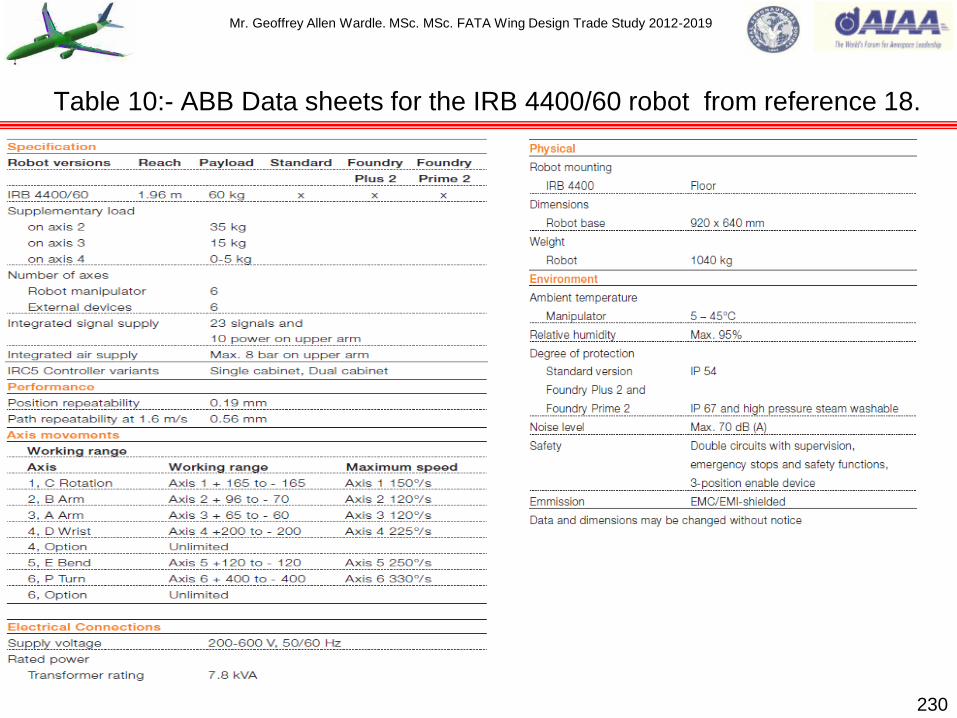
Mr. Geoffrey Allen Wardle. MSc. MSc. FATA Wing Design Trade Study 2012-2019
230
Table 10:- ABB Data sheets for the IRB 4400/60 robot from reference 18.

Mr. Geoffrey Allen Wardle. MSc. MSc. FATA Wing Design Trade Study 2012-2019
Robots by functions, fall into four basic categories:-
1)Pick and Place (PNP) this is the simplest of robots and its function is to pick up a part and move it
to another location. Typical applications include machine loading and unloading and general
materials handling tasks:
2)Point to Point (PTP) some which are similar to PNP robots, in that they move material from one
location to another, hence point to point, however it can move to literally hundreds of points in
sequence. At each point sophisticated PTP robots can stop and perform an action such as spot
welding, gluing, drilling, deburring, or a similar task:
3)Continuous path (CP) robot also moves from point to point but the path it takes is critical. This is
because it performs its task while it is moving. Paint spraying, seam welding, cutting and inspection
are typical applications of this type:
4)Robotic assembly (RA) articulated arm robot shown figure 78(b) is the most sophisticated robot
type of all and combines the path control of CP robots with the precision of machine tools. RA often
work faster than PNP and perform smaller, smoother and more intricate motions than CP robots.
A full description and definition of the proposed automated assembly study will be released in as
my full Kinematics and Aircraft Assembly Robotics Study by the middle of 2017. However currently I
have produced overview of industry development projects and a SCARA (selective compliance
assembly robot arm) kinematic model Human manikin and started interface studies (which can be
demonstrated at interview), which are covered in the accompanying presentation Kinematics and
Airframe Assembly Robotics Study (posted on my LinkedIn profile).
231
Robotic assembly in the development of the Baseline wing (continued).
Mr. Geoffrey Allen Wardle. MSc. MSc. FATA Wing Design Trade Study 2012-2019
The landing gear loads and reactions are the largest local on the aircraft structure, and therefore
transmitting such large local loads into the semi-monocoque structure of the wing box requires
extensive local reinforcement. Since the landing gear loads are large, there can be severe weight
penalties in the use of indeterminate structural load paths. An indeterminate structure is one in
which a given load may be reacted by more than one load path with the distribution being subject to
the relative total stiffness of these paths. In practice the manner in which the members share the
load can be determined but only when the design is finalized, and often overlapping assumptions
are made of the load paths which results in an over deigned heavy structure.
Often the gear loads can be spread out so as to keep the local reinforcement to a minimum, in the
case of the FATA as with the A350 family of aircraft the use of carbon fibre reinforced plastic
(CFRP) required a reduced point loading to reduce the amount of structural reinforcement required
in the aft spar. So as shown in figures 79(a), 79(b) for FATA a double side-stay landing gear was
developed similar to the Messier-Dowty A350 configuration where the aft side-stay is attached to
the auxiliary spar (or gear kick beam), thus reducing the reinforcement weight for the aft CFRP
spar. The support structure in the wing is designed to higher loads than the gear itself to ensure
that in the event of impact the gear will break off cleanly with the wing and not precipitate a fuel
tank rupture. The installation of the landing gear aft of the wing carry through box is shown in figure
79(c) and the requirement is for a 4.1m fuselage bay. For this study the landing gear loads are
developed using the methods in references 4 and 7.
232
Section 12:- Integration of baseline and developed aircraft nose and main landing gear.

Mr. Geoffrey Allen Wardle. MSc. MSc. FATA Wing Design Trade Study 2012-2019
233
Figure 79(a)/(b):- FATA Nose and Main landing gear used in for the design study.
Aft Stay
Figure 79(a) Sized Nose landing gear general
arrangement for integration in the FATA Design
Study.
Figure 79(b) Sized Port Main landing
gear general arrangement for integration
in the FATA Design Study.
FWD
FWD
Fwd Stay
Sliding piston
Main Fitting
Upper Torque Link
Lower Torque Link
Bogie Unit
Attachment fore
and aft pintle
Upper Drag Stay
Lower Drag Stay
Main Fitting
Steering
Assembly
Upper Torque Link
Lower Torque Link
Retraction Actuator Fwd Stay
Lock
Note:- Although Landing Gear Wheels and Struts have been sized these are not detail designs.
Lateral pintle

Mr. Geoffrey Allen Wardle. MSc. MSc. FATA Wing Design Trade Study 2012-2019
234
Figure 79(c):- FATA Main Landing Gear Installation checks in 4.43m bay.
4 wheel bogie MLG Installation check
(view from below).
FWD
OUT BD
UP UP OUT BD
FWD
4 wheel bogie MLG installation Section 15 Keel
panel kinematics clash check (view from below).

Mr. Geoffrey Allen Wardle. MSc. MSc. FATA Wing Design Trade Study 2012-2019
Section 13:- Integration of baseline and future concept engines.
The engine installation used on the baseline and developed aircraft in this study is in the standard
form of an under-wing nacelle pod, which for current designs has least effect on the aerodynamic
characteristics of the wing. For jet engines the wing nacelle pod mounting is the preferred option,
freeing more space in the wing to be used for integral fuel tanks, and imposing a torsional moment
on the wing which is desirable to offset wing wash-out at high angles of attack, and under
accelerating flight conditions. The thrust and inertia loading on the engine and the air loading on its
attached structure are carried back to the aircraft structure via the engine mounts. The engine and
support structure will react loads in any direction as Px (thrust), Py (side loads), Pz (vertical loads)
and the three corresponding moments Mx, My, and Mz as shown in figure 80(a). The nacelle,
nacelle strut, and engine mounts are designed to the ultimate load factors given in reference 7 for
this preliminary design study.
The pylon options for mounting the under-wing nacelle pod are shown in figures 80(b),(c),(d), where
the engines are supported by box beams of aluminium, titanium, or steel construction. The pylon is
attached to the wing front spar and lower skin panel with pylon loads distributed to the wing
structure in such a manner that wing box secondary deformation is minimized. In figure 80(b) the
pylon bulkheads take the engine loads onto the wing box and the pylon is attached to the front spar
by the pylon upper longeron, utilizing a rear drag strut to transfer the pylon lower longeron loads to
a point between the front and rear spar requiring skin reinforcement and not favored for this study.
In figure 80(c) the pylon is a box beam design and although this design puts more weight into the
pylon it saves weight in the wing box and reduces fatigue issues, and is the basis for the Alliance
pylon used on the A380 and is favored for this study.
235

Mr. Geoffrey Allen Wardle. MSc. MSc. FATA Wing Design Trade Study 2012-2019
236
Figure 80:- Possible wing pylon arrangements for the baseline aircraft.
Pz
(Side)
Mx
Mz
My Px
Py
(Thrust)
(Vertical)
Figure 80(a) Engine Loads.
Figure 80(b) Drag strut pylon installation.
Figure 80(c) Box beam pylon installation.
Figure 80(d) Drag strut pylon installation with
upper support arm (redundant support).
Mr. Geoffrey Allen Wardle. MSc. MSc. FATA Wing Design Trade Study 2012-2019
The pylon is attached to the wing through a fitting on the front spar for vertical and side loads, to a
fitting beneath the front spar on the wing lower surface for thrust loads, and to a fitting attached to
the wing box structure on the wing lower surface at the end of the pylon for vertical and side loads.
Spherical bearings are used at the pylon-to-wing attachments to avoid over constraint to the wing
lower front spar. Side fairing panels, with attached bulb seals cover the gap between the pylon
structure and the lower skin, and the pylon structure is identical left and right and is therefore
interchangeable. However the front spar fitting is complicated. In figure 80(d) the pylon has a
complex redundant support structure as detailed in reference 7 this is shown here for completeness
of options considered, although it is an inherently structurally fail safe design due to its redundant
load paths it is heavy and complex and was not considered for this study.
Figures 81, and 82 shows the proposed engine to be used, and the study engine nacelle and pylon
dimensions and OML layout which has an impact on the pylon and wing box structural design.
Table 11 gives approximate data for the Rolls Royce Trent 1700 for the A350-1000, in comparison
with the Rolls Royce Trent 772 for the A330 to illustrate the requirements growth.
Figures 83 shows the engine configurations for long and short / medium haul aircraft, and 84 shows
the additional loading introduced by the application of turbofan engine thrust reverses. Figure 85
shows current materials, and figures 86 through 89 show possible future engine concepts
considered for the future concept airframes to be studies in the third phase of this project, and
figure 90 shows the basis for the new airframe configurations to be studied in the third phase.
237
Baseline and future concept engines used in this study.
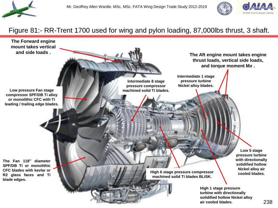
Mr. Geoffrey Allen Wardle. MSc. MSc. FATA Wing Design Trade Study 2012-2019
238
Figure 81:- RR-Trent 1700 used for wing and pylon loading, 87,000lbs thrust, 3 shaft.
The Forward engine
mount takes vertical
and side loads . The Aft engine mount takes engine
thrust loads, vertical side loads,
and torque moment Mx .
The Fan 118” diameter
SPF/DB Ti or monolithic
CFC blades with kevlar or
R2 glass faces and Ti
blade edges.
Low pressure Fan stage
compressor SPF/DB Ti alloy
or monolithic CFC with Ti
leading / trailing edge blades.
Intermediate 8 stage
pressure compressor
machined solid Ti blades.
High 6 stage pressure compressor
machined solid Ti blades BLISK.
High 1 stage pressure
turbine with directionally
solidified hollow Nickel alloy
air cooled blades.
Low 5 stage
pressure turbine
with directionally
solidified hollow
Nickel alloy air
cooled blades.
Intermediate 1 stage
pressure turbine
Nickel alloy blades.

Mr. Geoffrey Allen Wardle. MSc. MSc. FATA Wing Design Trade Study 2012-2019
239
Table 11:- RR-Trent 1700 & 772 data used in wing and pylon loading design calculations.
TRENT 772 Data. TRENT 1700 (Approximations).
Fan diameter 97.40” (2.474m) Fan diameter 118” (2.997m)
Basic engine Length 154” (3.912m) Basic Engine Length 191.7” (4.868m)
Basic engine weight 10,550lbs (4,785kg) Basic engine weight 13,700lbs (6,214kg)
Max thrust 71,100lbs Max thrust 87,000lbs
Number of shafts 3 Number of shafts 3
Compressor stages 1LP+8IP+6HP Compressor stages 1LP+8IP+6HP
Turbine stages 1HP+1IP+4LP Turbine stages 1HP+1IP+5LP
On wing podded length 236” (6.00m) On wing podded length 330” (8.40m)
On wing max podded
diameter 105” (2.67m)
On wing max podded
diameter 126” (3.20m)

Mr. Geoffrey Allen Wardle. MSc. MSc. FATA Wing Design Trade Study 2012-2019
Figure 82:- FATA Engine Nacelle and Pylon from AeroDYNAMIC™ sizings.
Dimensions used to model baseline
aircraft wing pylon and engine nacelle
derived from AeroDYNAMIC™ based on
the engine size and performance data for
the RR Trent 1700 HBT (public domain).
*Engine Nacelle Ground Clearance:- FWD
C of G position 0.76m and AFT C of G
position 0.78m.
A
6.40m
2.09m
11.10m
1.14m
2.15m
A
3.94m
3.17m
1.18m
240

Mr. Geoffrey Allen Wardle. MSc. MSc. FATA Wing Design Trade Study 2012-2019
241
Requires high:-
Overall pressure ratio:
Turbine entry temperature:
Bypass ratio.
Range
Fuel consumption.
Long / Medium-Haul (40,000-100,000lbs thrust):
Three-Shaft Configuration.
Short / Medium-Haul (8,000 - 40,000lbs thrust):
Two-Shaft Configuration.
Acquisition Cost
Maintenance
Simpler engine, hence moderate:-
Overall pressure ratio
Turbine entry temperature
Bypass ratio
Figure 83: - Engine type selection long and medium / short haul (RR), pylon implications.

Mr. Geoffrey Allen Wardle. MSc. MSc. FATA Wing Design Trade Study 2012-2019
242
Figure 84: - Engine thrust reversal conditions need to be considered for pylon loads.
Net 25% to 30% of engine thrust
acting in reverse thrust condition
through exit apertures.

Mr. Geoffrey Allen Wardle. MSc. MSc. FATA Wing Design Trade Study 2012-2019
243
Figure 85: - Current engine materials are considered for engine weights and pylon loads.
Low pressure Fan stage compressor
either SPF/DB Ti or monolithic CFC
with Ti leading / trailing edge blades.
Titanium.
Nickel.
Steel.
Aluminium.
Composites.

Mr. Geoffrey Allen Wardle. MSc. MSc. FATA Wing Design Trade Study 2012-2019
244 DATA SOURCE :- JEFFREY M. STRIKER Chief Engineer Turbine Engine Division Propulsion
Directorate Airforce Research Laboratory USAF Presentation POWERING UP 8th March 2007
Figure 86:- Highly Efficient Embedded Turbine Engine used in my future project studies.

Mr. Geoffrey Allen Wardle. MSc. MSc. FATA Wing Design Trade Study 2012-2019
245
Figure 87:- Highly Efficient Embedded Turbine Engine project focus.
DATA SOURCE :- JEFFREY M. STRIKER Chief Engineer Turbine Engine Division Propulsion
Directorate Airforce Research Laboratory USAF Presentation POWERING UP 8th March 2007

Mr. Geoffrey Allen Wardle. MSc. MSc. FATA Wing Design Trade Study 2012-2019
246
New Engine Architecture with reduced
parts count, weight, advanced cooling,
aerodynamics and lifting.
All engine
accessories
are electrically
driven.
Pylon/aircraft mounted engine
systems controller connected to
engine via digital highway.
Internal active magnetic bearings and
motor/generators replace conventional
bearings, oil system and gearboxes
(typical all shafts)
Generator on fan shaft
provides power to airframe
under both normal and
emergency conditions
Air for pressurisation / cabin
conditioning supplied by
dedicated system
Figure 88:- Example of Rolls Royce Electric Engine concept pylon mounted.

Mr. Geoffrey Allen Wardle. MSc. MSc. FATA Wing Design Trade Study 2012-2019
247
Gas generator
Large diameter
duct
Contra-rotating
fan
Contra-rotating
turbine
Blended wing aircraft may offer up
to 30% reduction in fuel
consumption - 40% if combined with
electric engine concepts
Figure 89:- Example of Rolls Royce advanced engine concept pylon mounted.
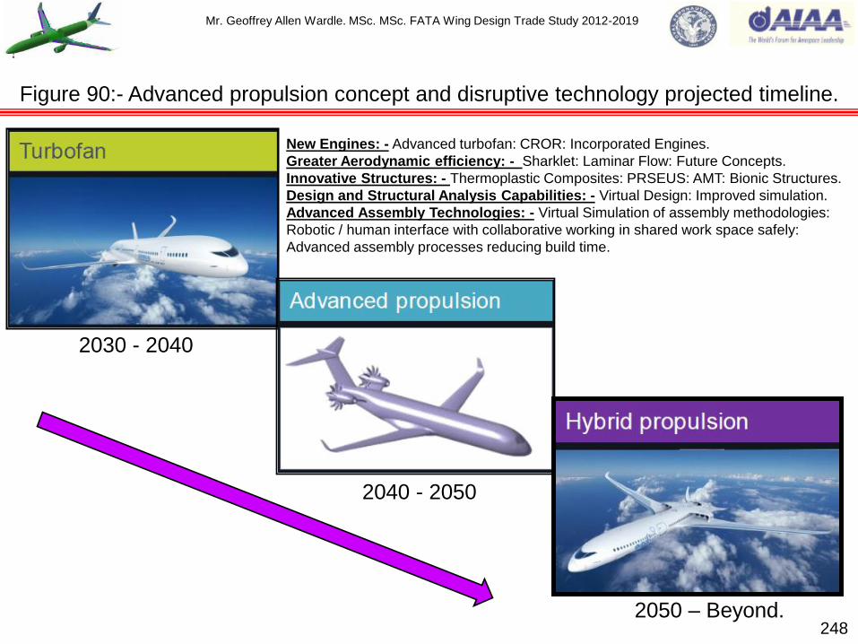
Mr. Geoffrey Allen Wardle. MSc. MSc. FATA Wing Design Trade Study 2012-2019
248
2030 - 2040
2040 - 2050
2050 – Beyond.
Figure 90:- Advanced propulsion concept and disruptive technology projected timeline.
New Engines: - Advanced turbofan: CROR: Incorporated Engines.
Greater Aerodynamic efficiency: - Sharklet: Laminar Flow: Future Concepts.
Innovative Structures: - Thermoplastic Composites: PRSEUS: AMT: Bionic Structures.
Design and Structural Analysis Capabilities: - Virtual Design: Improved simulation.
Advanced Assembly Technologies: - Virtual Simulation of assembly methodologies:
Robotic / human interface with collaborative working in shared work space safely:
Advanced assembly processes reducing build time.

Mr. Geoffrey Allen Wardle. MSc. MSc. FATA Wing Design Trade Study 2012-2019
249
Figure 91:- Concept basis for application of Future Integrated Structures and MAW.
Figure 91(b):- NASA BWB Aircraft Concept
Design. Figure 91(a):- Airbus Advanced Concept Aircraft
Design.
Mr. Geoffrey Allen Wardle. MSc. MSc. FATA Wing Design Trade Study 2012-2019
The structural layout and initial sizing of the major airframe structural components is an iterative
process, and implies that a synthesis phase is required to establish overall details before structural
analysis can be undertaken and the design refined, involving capture of the loads identified in
sections 4 and 5, and their integration into the major structural components, applying the
methodologies from references 4, 5, 6,7 and JAR 25.
Traditionally this synthesis phase has been based on the experience of the concept designer in
conjunction with the application of simple standard equations. However “expert” programs are
becoming more readily available which encapsulate previous experience and enable the synthesis /
analysis / refinement process to be undertaken in one seamless operation (e.g. AeroDYNAMIC™
see also my Cranfield University MSc thesis on Advanced Interdiction Aircraft on LinkedIn).
However, in order to use such systems effectively it is essential to have an understanding of the
means by which a structure reacts and transmits loads. All expert programs require an initial input
of some type for example to generate the structural layout of a wing the program may only require
the external geometry of the wing, and consequently the structural configuration produced will be
determined by the historical data built into the program. The ability to input a basic internal
configuration for the structure results in more versatility and more rapid convergence to a
satisfactory solution.
The approach applied in this project to accomplish the initial sizing of the main structural members
is a combination of both the „classical‟ approach where use is made of loading data obtained from
initial loading capture and analysis outlined in reference 4, to derive shear force, bending moment,
and torque diagrams, to evaluate the initial sizes of the main structural members of the airframe. 250
Section 14:- FATA baseline wing structural analysis and component sizing.

Mr. Geoffrey Allen Wardle. MSc. MSc. FATA Wing Design Trade Study 2012-2019
These initial sizings based on elementary theory will then be refined as defined 3-d solid structural
assemblies using Catia V5 GSA, and NASTRAN, for detailed analysis and sizing refinement, and
systems installation. This approach provides a good basis for understanding the way in which the
structure will function, and provides an early validation of the concept and serves as a datum
against which to check the output of a more advanced analysis.
Analysis of requirements-structural design data capture:- With the exception of specific ground
loading conditions an aircraft can effectively be considered as a free body in space. Therefore in
general the airframe will be in a state of acceleration in all six degrees of freedom. Therefore it is
necessary to include all of the inertial forces and moments in the analysis used to derive the basic
structural design data which is defined as:- shear force, bending moment, and torque diagrams.
This procedure consists of the following stages:-
1) Interpreting the loading requirements as defined in the design requirements:
2) Evaluating the consequent aerodynamic loads, wing lift:
3) Calculating the implied translation and rotational accelerations, using overall moments of inertia
consistent with local load distribution (masses and centre of gravity):
4) Distributing the aerodynamic loads and local inertia effects appropriately across the airframe.
When finite element modelling is applied these distributions will be allocated as local loads at
the structural nodes:
5) Employing the „classical‟ approach the loads are initially integrated across the airframe with
respect to length to obtain shear forces, and integrated a second time to get the bending
moments or torques.
FATA baseline wing structural analysis and component sizing (continued).
251

Mr. Geoffrey Allen Wardle. MSc. MSc. FATA Wing Design Trade Study 2012-2019
5) (continued) In this analysis integration starts from the extremities of the airframe and proceeds
towards the centre of gravity, because working from the outside in results in any accrued errors
being relatively small in comparison with the magnitude of the local data. Additionally any errors
due to inconsistent assumptions are more likely to occur in the wing – body interface region.
N.B. when the direction of integration is changed so is the sign of the result.
The process is applicable to all overall aircraft components for example, wing, fuselage, flaps,
engine nacelles, however in all cases the moments must be in total equilibrium.
Following load capture the synthesis procedure for initial sizing of the structural members will
require the following data to be determined and researched:-
a) Reasonably comprehensive load distributions, which may be used to derive the shear force,
bending moment, and torque diagrams, together with any particular concentrated load inputs:
b) Any relevant airframe life requirements and if appropriate, stiffness criteria, (see section 5 also):
c) An initial definition of the location of the main structural members, although there is always the
possibility of revision as the design progresses and the layout is refined (see section 6):
d) An initial choice of the airframe construction materials and assembly methods (see also
sections 7,8,9, and 10).
FATA baseline wing structural analysis and component sizing (continued).
252
Mr. Geoffrey Allen Wardle. MSc. MSc. FATA Wing Design Trade Study 2012-2019
Reference and datum lines:- It is important to define reference points and lines at the outset of
the structural design. Ideally a set of orthogonal axes passing through the centre of gravity of the
aircraft would be used. However this is not the most convenient since the centre of gravity moves
both longitudinally and vertically with differing fuel and payload conditions and therefore a
compromise has to be made to yield a consistent reference. A fore and aft reference located at the
nose of the aircraft is sometimes used but it is not helpful in terms of indicating the magnitude of the
forces and moments actually applied, and becomes inconvenient if the fuselage is stretched. A fore
and aft datum in the region of the centre of gravity range is better as shown in figure 92. Overall the
most suitable reference axes are considered to be:-
a) Aircraft centreline:
b) Fuselage horizontal datum in the side elevation unless the mean vertical position of the centre
of gravity is significantly removed from it :
c) Fore and aft axis located at a point 35% to 40% of the root chord, which has the advantage of
being in the region of the location of the aft centre of gravity and is close to the local mid-point
of the main span-wise structure, especially when the wing is unswept.
Swept lifting surfaces:- A particular difficulty arises when the layout of the aircraft uses swept
wings as in the case of the FATA configuration as shown in figure 93. It is logical to treat the outer
parts of the surface as an isolated structural member and to fix the span-wise reference axis along
the locus of say the 40% chord point. The problem arises in the root region where it is necessary to
resolve the bending and torsion couples into those appropriate to the overall axis system of the
aircraft. Thus what is a convenient definition for the analysis of local structural conditions becomes
inconvenient overall.
253
FATA baseline wing structural analysis and component sizing (continued).

Mr. Geoffrey Allen Wardle. MSc. MSc. FATA Wing Design Trade Study 2012-2019
254
x
z
y
Span-wise.
Locate at 35% root chord.
Centreline and fuselage datum.
Figure 92:- Structural design reference axes – (datum lines).

Mr. Geoffrey Allen Wardle. MSc. MSc. FATA Wing Design Trade Study 2012-2019
Figure 93:- Swept lifting surface datum lines (wing skin stringers omitted for clarity).
255
Orthogonal axes
Bending moment
Centreline
Oblique aircraft axes
Bending moment
Torque
Resolve at root station

Mr. Geoffrey Allen Wardle. MSc. MSc. FATA Wing Design Trade Study 2012-2019
The alternative is the use of an orthogonal axis across the whole span of a swept wing implies that
in the outer region the actual torsion couples are derived as a difference between two relatively
large numerical values and it implies the local resolution of couples at each span-wise station.
Often the most satisfactory approach is the former with careful thought given to obtain the correct
components of couples at the root junction. This problem is dealt with automatically when finite
element analysis tools are applied (Catia V5,R20 GSA, or NASTRAN), although care must be taken
in the selection of the element geometries.
In either of the approaches discussed above, when defining the bending moments, and torques it is
necessary to identify the load distribution across chord-wise strips. This is straightforward when
overall orthogonal axes are used since the chord-wise strips are in the flight direction used
conventionally to define the aerodynamic loading. When the wing is treated as an isolated structural
member the structural chord-wise strips lie across the stream direction and hence it is necessary to
resolve the aerodynamic information appropriately. For this study the former approach is applied to
the wing analysis using oblique aircraft axis at 40% wing chord.
Span – wise loading of swept lifting surfaces.
A simple evaluation of the additional load distribution on uncranked swept wings may be made
using the method of Stanton-Jones (ref 20). This method uses the Weissenger approach to
interpret experimental results. The shape of the distribution is completely defined by the position of
the span-wise centre of pressure of one half of the surface ŷ, which must be betwwen the limits
0.4< ŷ < 0.5 for the method to give acceptable results. 256
FATA baseline wing structural analysis and component sizing (continued).

Mr. Geoffrey Allen Wardle. MSc. MSc. FATA Wing Design Trade Study 2012-2019
257
(C)0
(C)b/2
b/2
Sweep of 0.25 chord line Λ = 35º
ŷ
y
Figure 94:- Swept wing span-wise loading notation for the Stanton-Jones method.

Mr. Geoffrey Allen Wardle. MSc. MSc. FATA Wing Design Trade Study 2012-2019
The notation for the application of the Stanton-Jones method of span wise wing loading estimation
for swept wings is shown in figure 94, and the equation for ŷ is as follows:-
ŷ = 0.42 + Am’ (4.45 + 5λ) tanΛ/m’ + 10.4𝜆1/2-6.7 x 10−3………(eq.1)
Where:-
A is the aspect ratio (b²/ S) = 10.15:
λ is the ratio of the tip to root chord = 0.27:
Λ is the sweep of the 0.25 chord line = 35º:
m’ = (1-MN²) where MN is the subsonic Mach number m’ = 0.2079.
Therefore:-
ŷ = 0.42 + 2.110185 (5.8) 3.368 + 1404 – 6.7 x 10−3 = 0.41
Hence the value of ŷ falls within the operational limits for acceptable results in the following
analysis.
*Let the value of ƞ = 2y/b, the for ƞ < 0.7:
c(y) CL(y) / (ċCL) = 1.28(1-ƞ²)1/2 + (14.13ƞ – 6.35)(ŷ – 0.425) .......(eq.2)
*and for ƞ > 0.7
c(y) CL(y) / (ċCL) = 1.28(1-ƞ²)1/2 + 4.25-53.8 (ƞ – 0.815)² (ŷ – 0.425) .....(eq.3)
According to ref 4 this method is likely to be as accurate as the votex-latice approach for this range
of lifting surfaces, a more general method is given in ESDU TD Memo 6403.
FATA baseline wing structural analysis and component sizing (continued).
258
Mr. Geoffrey Allen Wardle. MSc. MSc. FATA Wing Design Trade Study 2012-2019
AeroDYNAMIC Jet Designer 3.0 is a Whole Aircraft Analysis tool capable of determining and
reporting the following aerodynamic behaviour of a given configuration: - Lift: Parasite Drag:
Induced Drag: Supersonic Wave Drag: Mcrit: supporting the following analysis: - constraint analysis:
manoeuvre analysis: performance and specific excess power analysis: stability and control
analysis: sizing: weight prediction: optimisation: and cost analysis. The above are based on
geometry, mission and engine data as detailed below. The initial data required in order to construct
the AeroDYNAMIC Jet Designer 3,0 analysis model in the Main spreadsheet consist of data
parameters defining the fuselage, and parameters defining the wing, and empennage geometry for
determining the initial wetted area the configuration, and the fuselage is then further defined in the
geometry spreadsheet with the 20 specific geometry data points at 20 frame stations, and this
much more accurate data is used for the Swet.
The ultimate outputs of Jet Designer 3.0 are:-Customer Focus – Needs, House of quality: Design
Synthesis – Aircraft configuration modeling: Geometric Modeling – Areas and Volumes: Aero
Analysis – Parametric aerodynamic analysis: Propulsion Modeling – Parametric Trent XWB
published data: Constraint Analysis – Design Point: Mission Analysis – Better Mission Fuel
Fraction: Structural / Weight Prediction – Weights analysis: Sizing – Sized Wing Area, WTO, and
TSL: Performance Analysis – Ps: Cost Analysis – Acquisition and operating costs, life cycle:
Sensitivity / Optimization – “Best” Design, Cost trade: evaluated against the design mission figure
95, built in the mission builder module.
In order to generate the initial trade space the baseline FATA airframe employed the same fuselage
horizontal and vertical tail dimensions, as the Airbus A350, and the FATA baseline wing the
parameters required are shown in figures 96(a) and (b). 259
FATA baseline wing structural analysis and component sizing (continued).

Mr. Geoffrey Allen Wardle. MSc. MSc. FATA Wing Design Trade Study 2012-2019
260
Figure 95:- FATA baseline analysis using AeroDYNAMIC Jet Designer 3.
Twelve Disciplines: Definition
1 Customer Focus Determining the customer's needs and the priority which the customer gives to each need
2 Design Synthesis Creating design concepts that can reasonably be expected to meet the customer's needs
3 Geometry Modeling Representing the the shape of a design concept in sufficient detail that it can be analyzed
4 Aerodynamic Analysis Calculating the non-dimensional aerodynamic characteristics of the geometry model
5 Propulsion modeling Choosing an engine cycle and representing the variation of its characteristics with speed and altitude
6 Constraint Analysis Determining what combinations of wing loading and thrust loading will allow the concept to meet the ciustomer's needs
7 Mission Analysis Determining what fuel fraction the concept requires to fly customer-specified design missions
8 Weight Prediction Predicting the weight per unit area of the design concept's various components
9 Sizing Determining how large the concept will need to be in order to meet all the customer's requirements
10 Cost Analysis Determining how expensive the concept will need to be in order to meet all the customer's requirements
11 Optimization Finding the variation of the design concept that meets the customer's needs for the least cost
12 Performance Analysis Calculating the expected performance of the final optimal design, and comparing it to the customer's requirements
15,500km (9,631m) 370km
(230m)
45,0
00 f
t 13,7
16m

Mr. Geoffrey Allen Wardle. MSc. MSc. FATA Wing Design Trade Study 2012-2019
Figure 96(a):- FATA baseline geometry inputs for AeroDYNAMIC Jet Designer 3.0
Root Chord
Croot
Y
X
XWing
Tip Chord
Ctip
Wing Sweep ΛLE
Xengine
Yengine
Fuselage Length
Fuselage
Dia
Span b
Airframe Plan View.
Spreadsheet Nomenclature and Coordinate
System used in Jet Designer 3.0 to define
the FATA aircraft for evaluation. Note
Vertical Tail and Horizontal tail surfaces are
defined in the same way as the wing.
Root Chord
Croot
Tip Chord
Ctip
Span b
VT Side View.
261
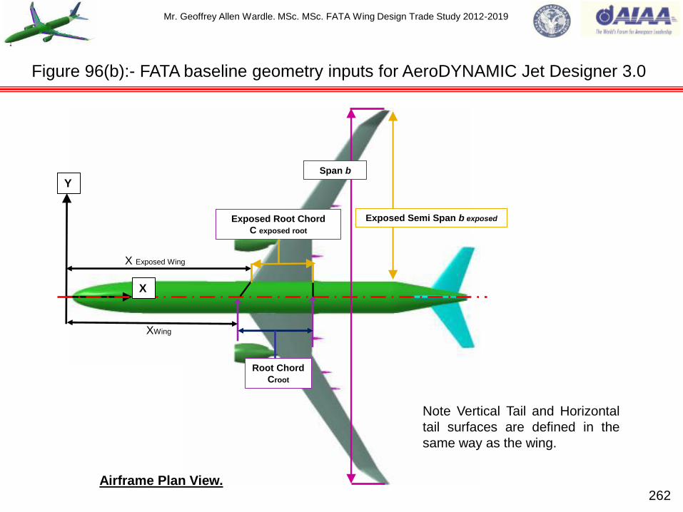
Mr. Geoffrey Allen Wardle. MSc. MSc. FATA Wing Design Trade Study 2012-2019
262
Figure 96(b):- FATA baseline geometry inputs for AeroDYNAMIC Jet Designer 3.0
Y
X
Root Chord
Croot
XWing
X Exposed Wing
Exposed Root Chord
C exposed root
Note Vertical Tail and Horizontal
tail surfaces are defined in the
same way as the wing.
Airframe Plan View.
Span b
Exposed Semi Span b exposed
Mr. Geoffrey Allen Wardle. MSc. MSc. FATA Wing Design Trade Study 2012-2019
1) NASA/TM-2009-215955:-Experimental Behaviour of Fatigued Single Stiffener PRSEUS
Specimens: by Dawn C. Jegley : NASA Langley Research Center: Dec 2009.
2) NASA/CR-2011-216880:-Damage Arresting Composites for Shaped Vehicles Phase II Final
Report: by Alex Velicki et al: NASA Langley Research Center: Jan 2011.
3) Morphing Skins:- Paper No 3216: The Aeronautical Journal: by C. Thill et al: Bristol University:
March 2008.
4) Aircraft Loading and Structural Layout: Professional Engineering Publishing: by Prof Denis
Howe: 2004: ISBN 186058432 2.
5) Composite Airframe Structures: Conmilit Press Ltd Hong Kong: by Michael Chun-Yung Niu:
1992: ISBN 962-7128-06-6.
6) Composite Materials for Aircraft Structures second edition: AIAA Education Series: by Alan
Baker et al: 2004: ISBN 1-56347-540-5.
7) Airframe Structural Design: Conmilit Press Ltd Hong Kong: by Michael Chun-Yung Nui: 1992:
ISBN 962-7128-04X.
8) A350XWB Aircraft Configuration: Airbus presentation 2007: by Oliver Criou.
9) NASA Supercritical Airfoils:- NASA Technical Paper 2969: by Charles D. Harris: NASA Langley
Research Center: 1990.
10) My Composite Design Capability Maintenance Studies: Private Study 2016: Mr. Geoffrey
Wardle published on LinkedIn.
11) My Metallic Design and FEA Capability Maintenance Studies: Private Study 2016: Mr. Geoffrey
Wardle published on LinkedIn. 263
Current reference material in use for the FATA paper for the AIAA list will be extended.

Mr. Geoffrey Allen Wardle. MSc. MSc. FATA Wing Design Trade Study 2012-2019
264
Current reference material in use for the FATA paper for the AIAA list will be extended.
12) NASA N+3 Subsonic Ultra Green Aircraft Research: by Marty Bradley (Principal Investigator
Boeing Research and Technology) et al: Boeing Research & Technology: Published April 20th
2010.
13) Boeing 777x Airport Compatibility ECCN:9E991: by Boeing Airport Compatibility Engineers:
Boeing Commercial Airplanes: Published July 2013.
14) Automated Assembly of Aircraft Structures: by Vorobyov. Yu. A. et al : Published by the
National Aerospace University “KhAl”: Kh-Al – ERA Consortium 2013.
15) Technology and Innovation for Future Composite Manufacturing GKN Aerospace Presentation:
by Ben Davies and Sophie Wendes.
16) ABB Robotics at www.abb.com/robotics for all product datasheets and surface models of the
IRB4400/60 robot and the 6650S_90 robot.
17) Damage Tolerance in Aircraft:- by Prof P.E. Irving Damage Tolerance Group School of
Engineering Cranfield University: Published by Cranfield University 2003 / 2004.
18) The Rapid estimation of span loading of swept wings: Cranfield College of Aeronautics Report
No 32, 1951: by Stanton-Jones.
19) Fully controlled production environment for autoclave injection processes: LOCOMACHS
Consortium: by M. Kleineberg et.al: Published 11/03/2015.
20) CODAMEIN Research Project EASA.2010.C13 Final Report 20120312: European Aviation
Safety Agency: by Zoltan Mikulik and Peter Haase: Published 12/03/2012.
21) AMC 20-29, Composite Aircraft Structure, Annex II to ED Decision 2010/003/R of 19/07/2010.

Mr. Geoffrey Allen Wardle. MSc. MSc. FATA Wing Design Trade Study 2012-2019
265
22) Design and Analysis of a Composite Fuselage: 3rd CTA-DRL Workshop on Design Analysis and
Flight Control September 14-16, 2009: S.J. Campos. SP, Brazil: by Marco Aurelio Rossi and
Sergio Frascion Muller de Almdeida ITA Mechanical Engineering Department.
Current reference material in use for the FATA paper for the AIAA list will be extended.