n analysis and design of an aeromedical evacuation litter ... · analysis and design of an...
TRANSCRIPT

- ~ ~ ~ ~ ~ ~ ~ ~ ~ : 2.--- -. . - Y Y- - . -- -. .. - -P .7 P
USAFSAM-TR 4 (111
n ANALYSIS AND DESIGN OF AN AEROMEDICAL- EVACUATION LITTER STANCHION
I :.
Malcolm A. Cutchins, Ph.D.< Winfred A. Foster, Jr., Ph.D.
Blane A. Hamner
Aerospace Engineering DepartmentAuburn UniversityAuburn, Alabama 36849-3501 ---CAEL-ECTE"•
SEP 10 1986 )August 1986 "LB
Final Report for Period May 1984 - September 1985
Approved for public release; distribution is unlimited.
Prepared for
L-- USAF SCHOOL OF AEROSPACE MEDICINESAerospace Medical Division (AFSC)
Brooks Air Force Base, TX 78235-5301
86 9 10 030

NOTICES
This final report was submitted by the Aerospace Engineering Department,Auburn University, Auburn, Alabama, under contract F33615-82-D-0627, job ordei7930-16-01, with the USAF School of Aerospace Medicine, Aerospace MedicalDivision, AFSC, Brooks Air Force Base, Texas. Second Lieutenant Erika J.Poleschner (USAFSAM/VNC) was the Laboratory Project Scientist-in-Charge.
When Government drawings, specifications, or other data are used for anypurpose other than in connection with a definitely Government-related procure-.ment, the United States Government incurs no responsibility nor any obligatiottwhatsoever. The fact that the Government may have formulated or in any waysupplied the said drawings, specifications, or other data, is not to beregarded by implication, or otherwise in any manner construed, as licensingthe holder, or any other person or corporation; or as conveying any rights orpermission to manufacture, use, or sell any patented invention that may in anyway be related thereto.
The Office of Public Affairs has reviewed this report, and it isreleasable to the National Technical Information Service, where it will beavailable to the general public, including foreign nationals.
This report has been reviewed and is approved for publication.
ERIA J. POLESCHNER, 2d Lt, USAF F. WESLE,, UOARDNER, Ph.D.Project Scientist Supervis r
DAVIS, Colonel, USAF, MC-et

UNCLASSIFIEDSECURITY CLASSIFICATION OF THIS PAGE ,
REPORT DOCUMENTATION PAGEla. REPORT SECURITY CLASSIFICATION lb. RESTRICTIVE MARKINGS
UNCLASSIFIED2a. SECURITY CLASSIFICATION AUTHORITY 3. DISTRIBUTION/ AVAILABILITY OF REPORT
Approved for public release; distribution2b. DECLASSIFICATION / DOWNGRADING SCHEDULE Approvedis unlimited.
4. PERFORMING ORGANIZATION REPORT NUMBER(S) 5. MONITORING ORGANIZATION REPORT NUMBER(S)
USAFSAM-TR-86-14
6a. NAME OF PERFORMING ORGANIZATION 6b. OFFICE SYMBOL 7a. NAME OF MONITORING ORGANIZATIONAerospace Engineering Dept. (If applicable)Auburn University USAF School of Aerospace Medicine (VNC)
6c. AODRFcq (Cft, State, and ZIP Code) 7b. ADDRESS (City, State, and ZIP Code)
Aerospace Medical Division (AFSC)Auburn, Alabama 36849-3501 Brooks Air Force Base, Texas 78235-5301
Ba. NAME OF FUNDING/SPONSORING 8b. OFFICE SYMBOL 9. PROCUREMENT INSTRUMENT IDENTIFICATION NUMBERORGANIZATION (If applicable) F33615-82-D-0627, Task 44
SCEEE-ARB 84/44
8. ADDRESS (City, State, and ZIP Code) 10. SOURCE OF FUNDING NUMBERSPROGRAM PROJECT TASK WORK UNITELEMENT NO. NO. NO. ACCESSION NO.
62202F 7930 16 01II. TITLE (Include Security Classification)
Analysis and Design of an Aeromedical Evacuation Litter Stanchion
12 O RqnNAL AI)THORIS)Cutchins, Malcolm A.; Foster, Winfred A., Jr.; and Hamner, Blane A.
13a. TYPE OF REPORT 13b. TIME COVERED 14. DATE OF REPORT (YearMonth, Day) 5. PAGE COUNTFinal FROMMay 84 TO Sep 85 1986, August 36
16. SUPPLEMENTARY NOTATION
17. COSATI CODES 18. SUBJECT TERMS (Continue on reverse if necessary and identify by block number)
FIELD GROUP SUB-GROUP Aeromedical evacuation; Airevac; casualties in war;
06 2 CRAF; Civil Reserve Air Fleet; litter stanchion;litters for wounded in CRAF
19. ABSTRACT (Continue on reverse if necessary and identify by block number)
" This report describes and documents an aeromedical evacuation litter stanchion designand analysis. The MSC/NASTRAN general purpose finite element computer code is usedfor the analysis. Also, details of 10 identical stanchion pairs actually built underthe effort are given. The stanchion pairs are yet to be subjected to structural testsat various G-levels and in appropriate directions. The final design is a 3-litters-on-one-side arrangement with support for the structure using seat tracks common to CivilReserve Air Fleet (CRAF) aircraft. Higher density litter arrangements such as 4-on-a-side or back-to-back 3 or 4 litter stanchions are explored. Floor loads exceed those.generally available for these cases.
20. DISTRIBUTION /AVAILABILITY OF ABSTRACT 21 ABSTRACT SECURITY CLASSIFICATION&IUNCLASSIFIED/UNLIMITED C SAME AS RPT 0 DTIC USERS UNCLASSIFIED
22a. NAME OF RESPONSIBLE INDIVIDUAL 22b. TELEPHONE (Include Area Code) 22:. OFFICE SYMBOL-Erika J. Poleschner, 2d Lt, USAF 512-536-2937 USAFSAM'VNC
O FORM 1473.64 MAR 83 APR edition may be used until exhausted. SECURITY CLASSIFICATION OF THIS PAGEAll other editions are obsolete.
.- -UNCLASSIFIED

TABLE OF CONTENTS
Page
BACKGROUND AND NINTRODUCTION ..................... I
THE BREADBOARD DESIGN . . . . . . . . . . . . . . . . . . . . . . . . 2
Background and Geometry . . . . . . . . . . . . . . .. 2
Design Features .... . . . . . . . 9
LITTER STANCHION STRUCTURAL ANALYSIS ................ 10
Typical Results . . . . . . . . . . . . . . . . . . . . . . ... 12
Grid Arrangement . . . . . . . . . . . . . . . . . . . . . . 12
Constraint Loads . . . . . . . . . . . . . ..... 12
Final Analysis Model and Results . . . . . . . . ........ 12
Non-NASTRAN Analysis . . . . . . ................. 18
PRODUCTION DESIGN CONSIDERATIONS .................. 19
AIRCRAFT COMPARISON . . . . . . . . . . . . . . . . . . . . . . . . . 21
PERTINENT FAA AND OTHER REGULATIONS . . . . . . . . . . . . . . .. . 22
ACKNOWLEDGMENTS . . . . . . . . . . . . 22 '
REFERENCES . . . . . . . . . . . . . . . . . . . . . . . . . . . 23
APPENDIX A: SUMMARY OF ALLOWABLE ULTIMATE BOEING 747FLOOR LOADS . . . . . . . . . . . . . . . . . . . . . . 25
APPENDIX B: CROSS-SECTION COMPUTATIONS . . . . . . . . . . .. . . . 27
APPENDIX C: COST CONSIDERATIONS .................. 31
LIST OF FIGURES %
Fig.No. %
1. Stanchion pair breadboard design.. . . . ... . . . . . .. 3
2. Exploded view of vertical assembly . . . . . . . . . . .. 4
,,"@ - . ".".". .' ' .. . ' .... ', =.'. ' -. e,. _. . - ,'_, ,' ,e. ,.4- " '--. " ",. "" .ii"""i,,",,""# . ,, = -*"-A a,.". ',

Fig.
No. Page
3. Section B-B through vertical member . . . . . . . . . . . . . 5
4. Exploded view of connection between horizontal assemblyand vertical assembly ................... *. 6
5. Exploded view of stanchion detail at and near eachfloor fitting . . . . . . . . . . . . . . . . . . . . . . 7
6. As-built stanchion pair (A) and welding jig (B) . . . . . . . 11
7. Preliminary NASTRAN-generated static analysis model . . . . . 14
8. Final NASTRAN-generated static analysis model ........ 15
9. Simplest telescoping design of the horizontal frameassembly . . . . . o. .. .. ... . . . . . . . . . 20
A-l. Allowable vertical and axial load combinations, BL67and 89.67 seat tracks (from Reference 11) . . . . . . . o . . 25
A-2. Summary of Boeing 747 floor load limits . . . . . . . . .. . 26
B-i. Cross section through square tubes . . . . . . . . . . . . . . 28
B-2. Cross section and table properties . . . . . . . . . . . . . . 28
B-3. Cross section through vertical litter arm support members . . 28
LIST OF TABLES
Table
No.
1. CONSTRAINT FORCE COMPARISON FOR DIFFERENT SPRINGSTIFFNESSES . . . . . . . . . . . . . . . . . . . . . . . . 13
2. CONSTRAINT FORCES FOR -9 G LOAD FACTOR . . . . . . . . . . . 16
3. COMPARISON OF SIMPLE ANALYSIS WITH NASTRAN ELASTICANALYSIS . . . . .... #. .. .. .. ... .. . 18
4. NON-NASTRAN STRESS CHECKS .... ............... 18
5. AIRCRAFT COMPARISON . . . . . . . . . . . . . . . . . . 21
iv
ANALYSIS AND DESIGN OF AN AEROMEDICALEVACUATION LITTER STANCHION
BACKGROUND AND INTRODUCTION
This research project developed as a follow-up from the earlier study (1)which evaluated the use of the long range international (LRI) portion of theCivil Reserve Air Fleet (CRAF) which could be used for large scale airevacuation of casualties. These casualties could occur in natural disasters,from an act of war, or from some national or international emergencysituation.
The Texas A&M study (1) tried to define a broad range of requirements to 4be met when using CRAP. One of the items which was included in this earlierstudy was a preliminary design for litter stanchions to be mounted in the CPFfloor seat tracks common to all CRAP aircraft. A very preliminary analysis ofthe structural integrity of the litter stanchion design was made to evaluateits feasibility for use in CRAF (1). No analysis, however, was conducted todetermine the loads delivered to the aircraft floor. The structural integrityis critical when considering the use of CRAF because of the generally lowerload-carrying capability of the floors in CRAF compared to the floors inmilitary transport aircraft. Also, the requirement that these aircraftmaintain certification by federal regulatory agencies for commercial use afterbeing used for evacuation missions requires that the aircraft floors not beoverstressed.
The objective of this research is to provide 10 copies of hardware for abreadboard design to be used in a test program for the purpose of verifyingthe structural integrity of the stanchion system. The stanchions must befunctional, structurally sound, capable of being installed on the existingseat tracks in a variety of aircraft and, upder the design load conditionsspecified in MIL-STD-008865A (2),must not deliver aircraft floor loadswhich exceed the allowable floor loads for a particular aircraft. The lastrequirement is by far the most stringent and the one to which the greatestamount of effort has been directed during this project.
Because of the sensitivity of the floor loads to changes in geometry andthe considerable differences between the various LRI aircraft of CRAF withregard to seat track geometry and the arrangement of hard points for makingattachments, the actual detailed hardware fabricated is limited to thatsuitable for a Boeing 747. This aircraft was chosen since it was the primechoice designated by the contract monitor. Available data included thegeometry of the seat track arrangement and the location of hard points andspecific data on the allowable floor loads for the 747. While the breadboarddesign described here is specifically sized for the 747, the design could alsobe used on other CRAF with changes. A modification of the breadboard designcould be made to include mechanical adjustment capabilities to allow thestanchion to be used interchangeably on other airplanes in CRAF. Allowableultimate floor loads restricted the resulting design to litters stacked nomore than 3 high. The requirement was due to the excessive floor loads caused
z.. - , . - .- "-°-' ' -' ' .- " -'- -'.- ' ,' -, -- . . . . . . -, -. ,- - ,- ., ,. '-

by more patient weight and by moments induced on the structure and hence onthe floor by the large lever arms which exist for the 4 litter case.
The transient dynamic load problem was not studied specifically in thisresearch. However, further investigations such as those done in earlierstudies (3-8) would be appropriate during the production design phase of thestanchion development program. Patient restraint problems would also besignificant to consider in a later analysis.
Patient restraint methods provide little if any restraint in thelongitudinal direction. This shortcoming is particuiarly important since themost significant dynamic loads are in the longitudinal direction.
THE BREADBOARD DESIGN
Background and Geometry
A major decision influencing the breadboard design is that since the C-9arms have been successfully surviving actual in-flight loads for some time andseem to be a sound, lightweight, re-dily procurable item, the breadboarddesign should incorporate means of accepting them. This item is a closetolerance part made of high strength material, and development of a similaritem exceeds the scope and available funds for this effort.
From our analyses (9 and this report) several other guidelines havedictated the way in which our breadboard design is arranged (Figs. 1-5). Forinstance, loading 4 parallel tracks with all the stanchion-pair loadsoriginating near their centerline showed that the 2 most outboard trackscarried very little load. There are also aircraft dependent limitations which
set upper limits to the El (bending rigidity) values of members that are"attached to more than two tracks laterally..." (11). This limitation is notspecified for all CRAF aircraft.
Early analysis indicated floor loads far too high for just 2 pickuppoints per stanchion (4 per stanchion pair). Therefore, to spread the load, 2along-the-track pickup points separated by a convenient distance are used inplace of each single pickup point. This arrangement is facilitated by theonly rather "healthy" (strength-wise) track hold-down fitting known to beavailable (10). This fitting has a 5-cm (2 in.)wide U-shape in line with thetrack (Fig. 5) as opposed to a U-shape perpendicular to the track forstanchions presently used on the C-9 aircraft.
Aircraft requirements that limit both the number of loads/bay betweenfloor beams, and/or magnitude of the loads for 2 loads/bay, also influence thedimensions of the breadboard design. The side-to-side floor beams on the 747,for instance, are 51 cm (20 in.) on center. To use the highest allowableloading arrangement, pickup points would have to be greater than 51 cm (20in.) apart (along the track), but this has proven impractical to implementusing 8 floor attachment points and the available floor fittings.
2a * -- *. . . ~-*.. .* -

J
.
SYM - SymmetryFF - Floor fitting
ST Seat trackVA - Vertical assyHA - Horizontal assyTA - Track & angles for
receiving litter supportarms (max 3 arms)> Except TA's on one sideonlyTo match Boeing 747 ST's,22.66 in.
Figure 1. Stanchion pair breadboard design (floor fittings not shown).
3i3 U]
~w
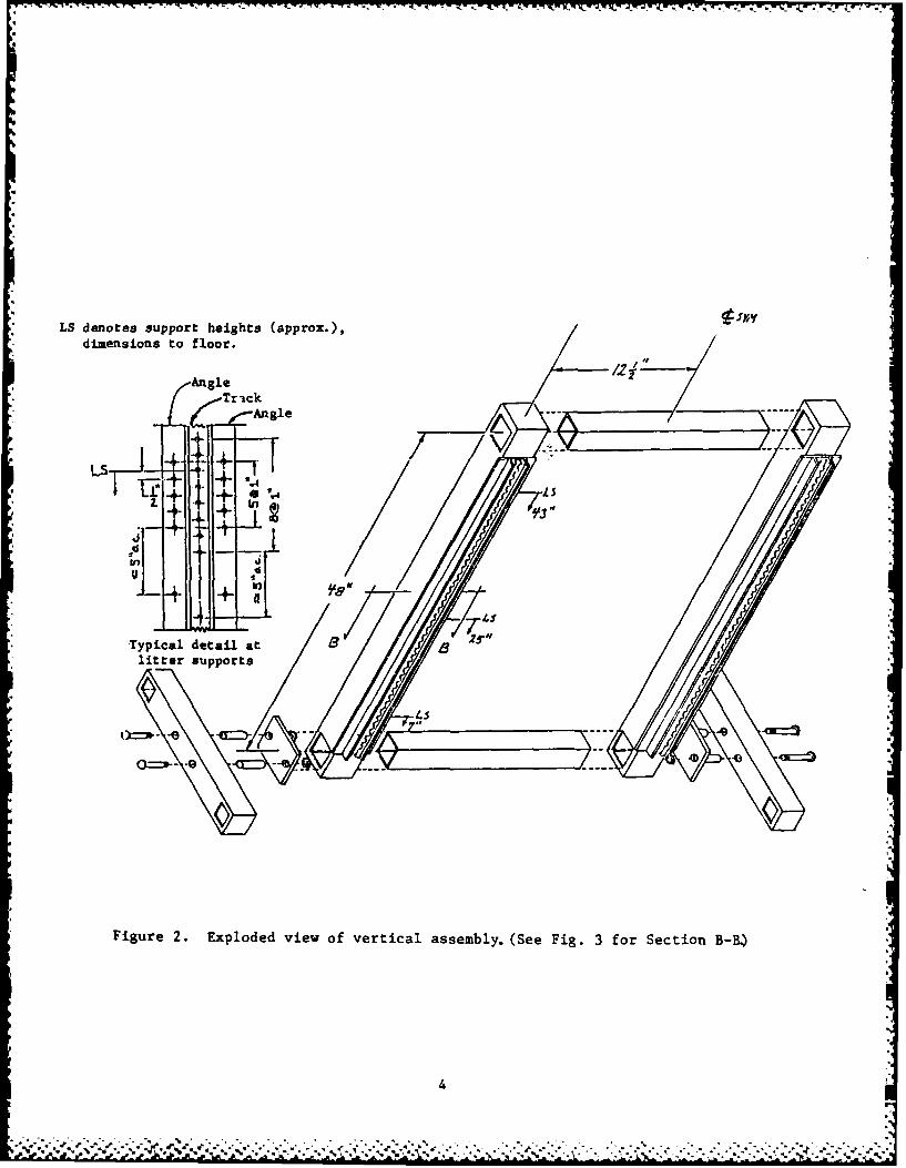
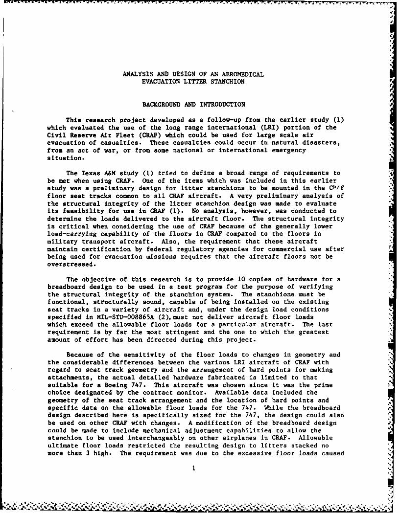
LS denotes support heights (approx.), t-lyy
*dimensions to floor.
AngleTrick( Angle p -
+ cc'
Typical detail at 8 is/litter supports
45i
* Figure 2. Exploded view of vertical assembly. (See Fig. 3 for Section B-B.)
4
~ ~ -- '.~.-. . .. C 2: ,c%

1 '
p.
CHURRKY SSPQS
I4k vr -
C-'I AAM4S ________ M
Note: All dimensions in inches F [AFTI AM5 ,
Figure 3. Section B-B through vertical member (Full Scale).
5 7
4..
"'" ;.""." ," '" " " ." ". " " "" "-''".-'.-'."-" ' -" -" ." -" -" -" ,.""-"".""-" ." "" ""."" "" "" •" •" -" " " '" " "" ." "".'"-" " ." ." ." ." ." 2 ."" "-"".""p.

YA
B - Bolt 1/2 in. x 3-1/2 in. grip
HA - Horizontal assyN - Bolt nut-P Connecting plateS - Bolt sleeveVA - Vertical assyW - Washer
Figure 4. Exploded view of connection between horizontal assembly (HA) and
vertical assembly (VA).
6

Z X2-x
WFV
B - olt /8 i. x2-1/ in.gri
BF -Browlin flor fitin
S - Bol sleev
ST - Set trac
Figue 5 Expode vie ofstachio deail t ad nar ech loorfiting
7K3

Some seat tracks are "harder" than others. The BL33.99 seat tracks inthe Boeing 747, for example, have considerably higher allowable loads (30% ormore) than other tracks in the 747 floor. A summary of allowable ultimateBoeing 747 floor loads and a typical floor-load restriction curve are shown inAppendix A.
Litter heights were specified in the task assignment of the contract tobe--bottom patient no less than 13 cm (5 in.) from the floor; and minimumspacing between litters will be at least 46 cm (18 in.). The analysis andBoeing 747 floor-load limitations from Reference 11 have dictated a "threelitters on one side only" arrangement and prevented more elaboratearrangements.
Of the near infinite number of possible design choices for a stanchionpair, the process of arriving at one to build and test can be summarized asfollows:
With multiple litter heights desired, vertical members at the littersupport points seem obvious (as opposed to some sort of A-frame, forexample).
The fore-and-aft position of these vertical members is a design variable.These vertical members could be rather close together like the as-builtstanchion pair, or closer, or they could be far apart. If vertical membersare far apart, there seems to be little advantage to use any other separationdistance other than a standard litter length 203 cm (80 in.) as premium spacewould be wasted.
Considering 2 vertical members 203 cm (80 in.) apart, loads as memberscantilevered from the floor are too high and a truss-like framing arrangementbetween them must be used. It is not feasible to have a 203-cm (80 in.) longrigid unit in terms of stow-away capability. A nonrigid arrangement requiringinstallation by unskilled labor with simple tools introduces severe unknownsinto the design. Columns or cables or straps of lengths in the neighborhoodof 2.5 m (8 ft) or so with installation tensions which cannot be guaranteed,and the use of "X'd" cables (one to resist forward loads and one aft loads) isnot, in our opinion, good design practice. The use of the "X'd" cablesintroduces redundancies into the design, adding to those associated withunknown floor rigidities which already exist. Also, cable whip phenomena orpossible column buckling in the case of structural failure of this arrangementcould contribute greatly to patient injury.
Spacing the 2 vertical members close together has 2 advantages:(1) stow-away and installation features of a compact vertical frame areadvantageous compared to the aforementioned cable-frame arrangement, and(2) "rigid frame" design yields a more efficient structure than one involvingpins, redundant cables, and/or long columns.
Selection of just how far apart the 2 verticals should be is certainly ahighly arguable point. lae authors have used 63 cm (25 in.),a dimension thatis compatible with all CRAF MED-E-VAC layouts. A longer distance between the2 verticals has two disadvantages: (1) litter stanchion pair weight isincreased, and (2) the number of in-line litters on the aircraft may bereduced. While not required, it is thought that nurse access between the
~~ ~ ~ ~ '~~~
. . . ... .-
~ * j . J A D. .*- ~ . . . - -. k .- . -

vertical members may become highly desirable in the implementation of thesystem.
Before arriving at the final configuration, numerous other geometrieswere analyzed. The original floor attachment geometry had 4 floor attachmentpoints on one side of the vertical members (1). Analysis of thisconfiguration revealed that the floor attachment points farthest from thevertical member only carried about 10% of the total load transmitted to thefloor. To more evenly distribute the load, the attachment points werearranged so that there were 2 attachment points on each side of the verticalmembers. This configuration better distributed the load between 4 floorattachment points, but under certain loading conditions the floor loads werestill excessive. To reduce the loading at the attachment points to acceptablevalues, the number of attachment points was increased by the inclusion of 4small beams running parallel to the seat tracks and placing the floorattachment points at the ends of these beams. The previously described floorattachment configuration is basically the same as the final floor attachmentconfiguration except in the final configuration the floor fitting locationsand the size of the small beams are optimized.
Design Features
The use of a rectangular frame made of square tubes for the verticallitter support frame provides a structural arrangement that is adaptable forvarious litter heights and which has both good torsional and bendingcharacteristics. Square tubes, while not the most efficient section forresisting high bending loads alone, are most desirable for the situatipn ofstanchions subjected to loads in 4 different directions. These loads lead tobending about 2 different axes, torsion, possible critical column loads, etc.
The 2 horizontal assembly frames (Fig. 1), of shorter spans and involvingsmaller tubing, spread the loads to seat track pickup points.
At each end of the vertical frame, plate and bolt arrangements are usedto attach the vertical frame to the 2 horizontal frames. This arrangementprovides for better storage/shipping geometry and allows the vertical frame tobe placed closer to the floor to keep the litters as low as possible. Thisconnection also eliminates a very unfeasible installation requirement oftrying to attach 8 tie-down points at once.
For the tie-down arrangement, off-the-shelf hold-down brackets weremodified to use 1 bolt at each connection to the horizontal track tie-downframe. This arrangement provides a pin connection and therefore some leewayin the dimensional tolerance along the track between the hold-down fittings.Floor expansion joints, however, could be a problem. (Such interruptions inthe 2.54-cm (1 in.) stud-to-stud dimensions are no problem if they occurbetween the stanchion pairs.) We expect that installation of the separatehorizontal frame assemblies will require 2 individuals; more than 2 hands arerequired to get all 4 support fittings of 1 horizontal frame in place, and atleast I person would have to hold the vertical frame while a second personattaches it to the 2 horizontal frames.
9

A number of alternative dimensional arrangements of the support fittinglocations were considered. Extensive iterations of the analysis along withconsiderations of availability of suitable structural members led to thearrangement shown (Fig. 1). The reason for the 20-cm (8 in.) and 10-cm (4in.) offsets of the support fittings on the horizontal assembly is to decreasethe severity of the loads in the dominating -9 G case. The vertical loadsapplied to the seat tracks are excessive for this case with 15-cm (6 in.)symmetrical spacing (i.e., 20 cm (12 in.) between fittings) and for 56-cm(22 in.) spacing. Table 2, to be discussed later, further addresses thismatter. Reducing these vertical loads to those within the maximum allowed(11) has been the driving force in the breadboard design iterations.
An actual photograph of one of the as-built stanchion pairs is shown inFigure 6(A). Only the second highest litter arms are attached. Due to thecamera's downward angle, there is some distortion that makes the lower partsof the stanchion pair seem smaller than they really are. Also shown is awelding jig in Figure 6(B) that was used for stanchion pair fabrication. Thejig was made from actual track, and the floor fittings shown were actually heldin place for welding of the stanchion.(Only 6 of the 8 floor fittings areshown-the other 2 are just out of camera view to the top of the photograph.)
LITTER STANCHION STRUCTURAL ANALYSIS
The litter stanchion design requires an analysis to evaluate thestructural integrity of the stanchion and to determine the loads transmittedto the CRAF aircraft. The structural integrity of the stanchion is determinedfrom the ultimate strengths of the materials used. The floor loads aredetermined from the reaction forces generated at the points where thestanchion is attached to the aircraft floor. The allowable floor loads forthe Boeing 747 are defined by Boeing document No. D6-13427 (11). The requiredequivalent static loading conditions which are used in the structural analysisare obtained from MIL-STD-008865A (2).and the Task Description.
The structural analysis was done using the finite element method and theMSC/NASTRAN general purpose finite element computer code. Beam elements withup to 6 degrees of freedom at each end are used to model the stanchion as athree-dimensional frame. Although the real loads applied to the stanchionwill be of a dynamic nature, only static analyses are documented here,consistent with the load factors referenced in MIL-STD-008865A (i.e.,equivalent static loads which include a built-in dynamic load factor).
The most difficult part of the modeling was the determination of theappropriate constraint conditions to apply at the interface points between the
stanchions and the aircraft floor. Several possibilities were considered forapproximating the connection between the stanchion studs and the slotted floortrack support. The first possibility consisted of assuming that a rigid orclamped condition existed at the attachment points. However, because of thelack of actual fixed constraints against bending moments and torques, thisassumption was not very accurate. This method, however, provided an upperbound for the floor loads. The second assumption considered the attachmentpoint to behave as a ball joint (i.e., only translational degrees of freedomwere restrained and therefore no bending moments or torques were transmittedto the floor). This method was a somewhat better assumption but still did not
10

A
B~
h.0.

account for any loose fit between the stanchion and the floor, or for theelasticity of the floor, or floor fitting. The modeling of the loose fitwould require an iterative and/or nonlinear analysis to be performed, ananalysis which was not done because of cost and time considerations. Theelasticity of the floor and fitting was finally modeled by using linearsprings in each of the three possible translation directions, the spring beingconnected between the stanchion attachment points and an assumed rigid floor.This model provides a more reasonable assessment of the floor loads. Themajor uncertainty with this assumption is the magnitude of the springconstants. However, the analysis shows that the magnitude of the floor loadsis not strongly dependent on the spring constants used. Table 1 is evidenceof this analysis (3 litter, -9 G load factor, longitudinal case).
Typical Results
Grid Arrangement
To discuss typical results, refer to Figure 7 and the grid numberingscheme shown in the NASTRAN-generated isometric view of our most thoroughlyinvestigated stanchion pair analytical model with 16 C-9 litter support arms(the 8 litter case).
Constraint Loads
Since our task assignment included the necessity not to overload the seattracks in existing aircraft, much attention has been given to the constraintforces (constraints at grid points 2, 3, 19, 20, 56, 57, 60, and 61; Fig. 8).These forces are readily available from NASTRAN; however, some judgment as totheir realistic values must be made as such values are very dependent on theassumptions of the constraints. Our analyses have centered on 2 constraintarrangements: (1) each constraint grid point is prevented from translating atall in any of the 3 directions (referred to as a "rigid" constraint), and (2)each constraining grid point can move against elastic springs. The springssimulate the nonrigid, but reasonably stiff, aircraft floor structure to whichthe seat tracks are attached. (The fitting itself provides some of thisflexibility as well.) The differences in constraint forces are quitesignificant. For example, consider the constraint forces tabulated inTable 2. Note the significant difference especially in the longitudinalconstraint forces for the -9 G case. The only differences in the computerruns here are the rigid vs. elastic constraints. A comparison of these loadswith the allowable loads of Boeing Document No. D6-13427 (11) clearly indi-cates that a maximum of 3 litters (on one side) with elastic constraints is,in the authors' opinion, the only reasonable case to consider for the finalbreadboard design. Table 3, to be discussed later, supports our conclusion.
Several other support-fitting separation distances different from thefinal arrangement were thoroughly investigated. Similar trends in constraintload patterns were present.
Final Analysis Model and Results
A sketch of the analysis model of the as-built stanchion pair is shown inFigure 8. Both grid numbers and beam element numbers are indicated on thefigure. Some of the pertinent cross-sectional computations are given in
12
'.P-'d'_ '&*!

TABLE 1. CONSTRAINT FORCE COMPARISON FOR DIFFERENT SPRINGSTIFFNESSES: -9 G LONGITUDINAL LOADING
Grid Point* k - 500 lb/in. k - 1000 lb/in. k - 2000 lb/in.
Vertical Constraint Forces
2 1760.1 1717.1 1691.9
3 655.0 580.7 507.3
19 -655.0 -580.7 -507.3
20 -1760.1 -1717.1 -1691.9
38 2032.8 2052.4 2048.1
39 1079.2 1207.7 1349.4
41 -1079.2 -1207.7 -1349.4
42 -2032.8 -2052.4 -2048.1
Lateral Constraint Forces
2 358.3 202.0 -2.5
3 344.6 410.0 492.5
19 -344.6 -410.0 -492.5
20 -358.3 -202.0 2.5
38 734.8 819.1 907.0
39 283.2 321.7 394.3
41 -283.2 -321.7 -394.3
42 -734.8 -819.1 -907.0
Longitudinal Constraint Forces
2 1334.0 1362.7 1416.8
3 1298.7 1295.2 1287.5
19 1298.7 1295.2 1287.5
20 1334.0 1362.7 1416.8
38 668.0 679.2 703.3
39 621.9 585.4 515.0
41 621.9 585.4 515.0
42 668.0 679.2 703.3
*Grid points are consistent with those shown in Figure 8.
13
S"".... % % % '+ , .4o * . , , . -,'. , • -'4 .,- , - -" -" " , , - " , " ,''- "' Q

-4 AumtTYP.) 9 PLACESSAC sloc
d7
Figure 7. Preliminary NASTR.AN-generated static analysis model.
41

N - Grid numbers
(N) - Beam. element nos. 4
N - Constraint grids
Lila.
9-
31(.)
3)(ro) W
Figure 8. Final NASTRAN-generated static analysis model (3-D elastic springs ateach constraint omitted).
%15

4 * -i --- w jv - .N -. U.V 1- 7 N ,
00(TA kn -41 00 c0 '.0 - c00n m% C7~% en un LA (
a I-. Go0 '0 0 i4) 4 r- -4 a-4 -r C
0A V) 0 0 0l m A 'A 0nen
1-4 V 0- M -
4)0 0 0VU
r. 0% ON 1. 'A '.D %a0 IA *4 ca .4 wa) 04 Nq N N 0 ul LA 0 00 0c 00 0a0 Go (n en 00 N4 ..4 14 N1 .14 r-4 .,4 .4~ 8 -4 N4 en N4 C4 (n 14 W sw 0u
W 0) w w
CD 0 c0 0% 0%l 0C.400 N 00 c0 -4 r- ts t- f-. . 4 %~
IA en1 r- v CO) IT7 Do 00 -47
a A 'a '.0 cc 0
a w~ -P-s I. -t ' 00 0% 'A
*.' 0 v-S . P.0 04- C*4 '.0 '0ccl m C -4 CN- cn c 4 14 (n
1-4 0 % 0% CF% 'A) 0% ON 'A0 % 0% 'A) 'A 'A) '
co cl) rJ 0 4 cns ce) -4 -4 cn
P-4 V0
U 0 0 0)
41i4 w
N4 W ~ c t ' . A.100 A A cA NI No C4 %D "4 "A 4.)
4) P . f%. %D r-. rs c1 r r- - a .iu* .3r 0T LA tn T cA 'Au 000 00 %. 0%
Ai w- w c. to
(isO 00Q P 0 044.) 4.) W)J 4)%
4.s.) 4) .
N16 ~ - ,. .
v-- vs p- J p3 p.

co 9 ('9 ('M ('9 co -c 0 r- 0- .- n c' '9 .40% m m ' 0% m (' LAl Ln en Q? co Go - 0 'A in 0
to 0 0n 0 en - %09 -D r- -4 I- (n 0 en on c-490 0% ' 0 -4 -40 IA L ' 0 0 A
%0.- 00 '-4 T (n -4 NI 1- 0 0 c 00 N*to 0 N '. M0 Q? -tT '0 -4 % D-4 I4 C-4 -4 N N .
-4 Go '- 0 C% r- r- 0 -T -4 -4 -T -4 e'9 en -40v en9 -4 4 m' Ln -4 4 'D 3%. P%. I- - 0% N 4 as0m co f-s 4- OD % co 0 0% - T IT 1? - 0 LA) LA 00d 4 4 -I-4 I I ~ 4 I
LMen9 .% co N1 .4 N1 .-4 -4 0 0% 0% 0% '.0 04 -I '
0 0 0 %D 0% '0 . 0% C04 N0 Nr W A 0 L040 N 0 0 m' ' M ~ .- 1-4 i-s F LA LAM -
cc ON0 - -T ON 0% r- - 0% . -4 .-4 .-4 .4 (en '9 .4
'-4 A0
0 -t U
-4 -4 0 I
o) IT 4.C434 m o 0 0 co1 4 I(a co ON C% c t %0 %0T r n C4e 1 1
coU -4 -T7 c 0 %0 %0 0 4.3 N t -7 N N - -
N to 0 is - . . (9 U ~ 0 0 ~ - ' '' -
-0 NO IT 1? I0 0I 14 I cI
-4
0 '-4 cr- 4m -4 0n ON in 0n 0n 'Aw LA% '0 0f 0- '0w" 0 m 0 0 LA ON 0 , LA) Ln P%. P, in- vs LA r-
0 T N 0 N o N T N ? N N N0 NT4 n e 4 C n c 1
C49 LA OA N . 0 4 A0 en0 '0 0 00 r- a% 004 CA0% 0 4L LA 0n %0 LA4 C4 W) 'A LD %0'A LA
U 0 0% % 0 0 0 -s 'A A - F ' 'A17

Appendix B. G-load factors of ±1.5 G side, 9 G forward, 4.5 G down, and 2 G upwere used. Due to certain axes of symmetry, these factors represent athorough check on the various loading conditions.
*Non-NASTRAN Analysis
There are many analysis considerations in an effort such as this, but inthis day of sophisticated finite element analysis software such as NASTRAN,many such considerations are hardly worth documenting extensively. Interest-ingly, however, a "by-hand" analysis did lead the way to the more realistic(in our opinion) constraint conditions discussed elsewhere. This analysisserved as a good check on the NASTRAN model. For instance, Table 3 revealsgood agreement between an elementary analysis and a complete NASTRAN model.
TABLE 3. COMPARISON OF SIMPLE ANALYSISWITH NASTRAN ELASTIC ANALYSIS
8 litters (4/side) 6 litters (3/side)
Highest vertical floor load 10214/7600* 5506/4315
Lowest vertical floor load 2042/2142 1101/1097
Shear load at floor 2394/2433 1796/1877to 2623 to 1982
*Simple analysis/NASTRAN analysis with elastic constraints (throughout
table). All loads in lbs.
More importantly, NASTRAN does not perform a number of calculations.The stress checks that we performed are summarized in Table 4.
TABLE 4. NON-NASTRAN STRESS CHECKS
Max load Max stressPart Condition description Max load (lbs) (psi)
1 cm (1/2 in.) Combined tension and 9 G Case 5558(s) 49539diameter bolt single shear 3846(t)
1 cm (3/8 in.) Double shear 9 G Case 1291 11691diameter bolt
Floor fitting Bearing at bolt 9 G Case 2052 21892shear tearoutmaximum section
tension
10 cm x 10 cm Buckling 9 G Case 2998 -11265
beam-column
(4 in. x 4 in.)
18

* . 1 .fl V a 2r, a1. F . .ly -. V
PRODUCTION DESIGN CONSIDERATIONS
The major considerations in a production design are at least twofold.First, should certain CRAF models be excluded from use due to theunfeasibility of having stanchion pair that can fit in all aircraft ofinterest? Our recommendation would be to exclude the -10 through -50 modelsof the DC8 since on each side of the centerline, seats are supported by a walltrack (in the fuselage wall, not in the floor) and a floor track. One coulduse jointly the 2 floor tracks on each side of the aircraft centerline, butthe separation distance is 127 cm (50 1/8 in.); quite different from otherCRAP aircraft. DC8-60 models and other models of interest are probablycomparable enough to all be used in the present scheme.
Secondly, a stanchion pair to fit as desired in the multiplicity of CRAFaircraft would need a butt-line adjustment to fit track-to-track centerlinedimensions of 48 cm (19 in.), 50 cm (20 in.), 52 cm (20.75 in.), 57 cm (22.6in.), and 81 cm (32 in.). "Telescoping" of the track-to-track connectingmember of the horizontal frame of the breadboard design has possibilities, buttrade-offs with production limitations will most likely dictate the approachtaken. The breadboard as-built stanchions do not have this feature. It ispossible that 4 dimensions (of the 5) might be incorporated into theproduction design with some means for handling the 48-cm (19 in.), 50-cm (20in.), 52-cm (20.75 in.), and 57-cm (22.6 in.) cases with a single, unalteredstanchion-to-floor fitting arrangement. This feature would placethree-dimensional loads on the floor track, however, whereas most of theaircraft load data available deals with two-dimensional loads (up and axial orup and side, etc.). This feature could also dictate the development of a newfloor fitting that is beyond the scope of the present effort.
Alternatively, a double stud fitting may be available or a new designmade so that the U-shape of the fitting would be perpendicular to theBrownline fitting used in the breadboard design (Fig. 5). Then, by slidingthe fitting to different butt-line positions and using quick release pins, thevarious track-to-track dimensions could be handled. This design would requirea different arrangement of the horizontal frame than the present breadboarddesign. Such an alternative opens up "Pandora's Box" again concerning numberof floor support points, floor rigidity, etc.
One appropriate telescoping design is shown in Figure 9. This designwould be a modification to the present breadboard stanchion horizontalassemblies (HA in Fig. 1). The 2 bolts shown in the slots are the bolts whichattach the horizontal assemblies to the vertical assemblies (B in Figure 4).An 8-cm (3 in.) slot and the use of telescoping square tubes would provide foradjustment to fit the 48-cm (19 in.), 50-cm (20 in.), 52-cm (20.75 in.), and57-cm (22.6 in.) cases described previously. The design will not work for the81-cm (32 in.) case due to the dimensions involved (i.e., the largest tube'slength is limited by the narrowest track-to-track centerline; there isinsufficient room for the slotted tube to meet both extremes).
19
~~~*~ ..~ . . ...... . . . .a* . '~ . ..

Adj us tmeri t h oles f or d
Track 4 spoaces Track
SYM.
2 2 "x22" Tube13"Ma.
3"1 x 3"1 x -, Tube 9.5"(Min.)
19" Minimum A
22.66" Breadboard, as built
Figure 9. Simplest telescoping design of the horizontal frame assembly.
20

Other production design considerations include, but are not limited tothe following:
" Costs; see Appendix C for a rough approximation.
" Are floor track splices significant enough to deal with from loads andfrom installation restriction standpoints?
" Do the floor tracks with electric service in the DC1O interfere withthe litter stanchion concept? Or vice versa?
" Which of the multiplicity of G-load factors used by the differentmanufacturers dictates the minimum weight stanchion design (as opposedto going just by the MIL-spec or a contract task assignment)?
" What technique is most desirable for production litter stanchionconstruction? Fabrication used for the breadboard model may notbe consistent with the most feasible production design methods.
" Would some combination of single stud floor track fittings and doublestud fittings work better for the production design?
" Would it be best to use an off-the-shelf floor fitting as thebreadboard design has done, or develop a new floor fitting?
" Would it be best to use the available C-9 litter support arm (as thebreadboard design does), or could some sort of snap-in-place arm beincorporated into the production design? Storage improvement andquick-installation features could certainly be improved by such anarrangement.
AIRCRAFT COMPARISON
The major differences in the CRAY aircraft that are of interest here arethe variations in track-to-track dimensions in the butt-line direction(previously discussed), and in the various floor-load limitations. Sincenearly all of this information is proprietary (13,14,15), it is shown in Table5 identified only as aircraft A, aircraft B, etc.
TABLE 5. AIRCRAFT COMPARISON
Basic track-to-track Floor beam Floor load
Aircraft dimensions (inches) o tO (inches) allowable
A 22.6 20 See Appendix A
B 20.75 Unknown Proprietary
C 19 (near t) Unknown Proprietary19 (near windows)
D 20 Unknown* Proprietary
*16 inches required between floor fittings.
21
_2_/ , ' '-. ,' . .' o ,% %.-, -. .'. .. '. ', j--.. ... , . . .'.' ... . .".j .. % < .% % %

It is possible that a restriction of the number of models in whichstanchion pairs may be used could result in an arrangement of fewer floorattachment points due to higher allowable floor loads for certain aircraft.
PERTINENT FAA AND OTHER REGULATIONS
The primary importance to this effort is the Boeing requirement (11, p.53) that tests of structures (furniture) to be subjected eventually to flightconditions must be accomplished with simulated aircraft floor supportstructure. While this requirement refers to flight hardware, our NASTRANanalysis has shown the critical nature of such support conditions, and theauthors strongly agree with this Boeing requirement. To test the structure ona."rigid" test frame is probably meaningless.
Federal Aviation Administration (FAA) regulations of interest aresummarized in Code of Federal Regulations (12). Many of these regulations areconsistent with the Task Directive of this effort. Two regulations stand outas exceptions: (1) the contrast in patient weights 77.11 kg (170 lbs) FAA,113.4 kg (250 lbs) USAF, and (2) the requirement that:
"Eac. berth installed parallel to the longitudinal axis of anairplane must be designed so that the forward part has apadded end-board, canvas diaphragm, or equivalent means that
can withstand the static load reaction of the occupant whenthe occupant is subjected to the forward inertia forcesprescribed..."
The latter may be a very key element in eventual success of protection of thepatients and could also affect the assumed loading arrangement.
Dynamic tests rather than static tests could also significantly affectresults. A new FAA regulation on dynamic tests (S 562) is scheduled to bepublished in the fall of 1985. An example of the significance of dynamics is:in a near-ultimate load situation (e.g., -9 G's or 4.5 G's) when deflectionsare large and probably nonlinear, is the assumption of one-fourth of thepatient's mass acting at each litter support appropriate? Or does the inboard(less deflected) litter support take on a greater percentage of the mass?Static tests will not answer this question.
ACKNOWLEDGMENTS
We gratefully acknowledge the special assistance of Brownline Corporationof Torrance, California, especially Craig Reisacker, and the cost sharingsupport of Auburn University, specifically the Engineering Experiment Station.Appreciation and thanks are also extended to Bill Holbrook, a machinist in theAerospace Engineering Department Shop, for his indispensable experience,advice, and skilled craftsmanship.
22

REFERENCES
1. "An Evaluation of the Use of CRAF in Air Evacuation of Casualties,"Center for Strategic Technology, Texas A & M, Dec. 1983.
2. MIL-A-008865A(USAF), "Airplane Strength and Rigidity MiscellaneousLoads," as amended 17 February 1977.
3. Bolukbasi, A., and Laananen, D., "Nonlinear Finite Element Method inCrashworthiness Analysis of Aircraft Seats," J Acft, pps. 512-519 July1984.
4. Brown, J. C., and Tidbury, G. H., "An Investigation of the Collapse ofThin-Walled Rectangular Beams in Biaxial Bending," Int J Mech Sci, Vol.25, No. 9-10, pp. 733-746, 1983.
5. Kecman, D., "Bending Collapse of Rectangular and Square SectionTubes," Int J Mech Sci, Vol. 25, No. 9-10, pp. 623-636, 1983.
6. Welch, R. E., and Yeung, Kim S., "Refinement of Finite Element Analysisof Automobile Structures Under Crash Loading, Volume II: TechnicalReport," U.S. Department of Transportation, October 1977.
7. Laananen, D. H., "Development of a Scientific Basis for Analysis ofAircraft Seating Systems," FAA-RD-74-130, January 1975.
8. Laananen, D., Balukbasi, A., and Coltman, J., "Computer Simulation ofAircraft Seat and Occupant in a Crash Environment -Vol. I -TechnicalReport," DOT/FAA/CT-82/33-1, March 1983.
9. Cutchins, M. A.; Foster, W. A., Jr.; Hamner, G.; Tinker, M.; "Design ofAeromedical Evacuation Litter Stanchion for Use in CRAF Aircraft"(Interim Technical Report), December 1984.
10. Brownline Cargo Restraint Equipment Catalog No. 206, Brownline Divisionof AAR Brooks and Perkins, 2950 W. Lomita Blvd., Torrance, CA 90509,1980.
11. "Design and Installation Requirements for Main Deck Furniture" (forBoeing 747), Boeing Document No. D6-13427 (undated).
12. Code of Federal Regulations (CFR), "Aeronautics and Space," Jan. 1, 1985.(Structural requirements: 23.613, 23.615, 23.621, 23.625, 23.785,25.561. Section 23.785 deals with "seats, berths, safety belts, andharnesses".)
13. Private correspondence from D. M. Motley, Aeromechanics Department, Dept.72-73, Zone 53, Lockheed-Georgia Co., Marietta, GA 30063 (undated;received September 12, 1985).
23
"-' -',3".LI ''' \,-""" " .' " -" "-"- ."- .". . .',,L,," ,,..'"..-'. , -- C" ; i' ' ;

14. Private Correspondence from J. G. Lewolt, Director of Engineering,Technology, Lockheed-California Co., Burbank, CA 91520, October 24,1985.
15. Private correspondence from R. J. Hunt, Manager-Engineering ContractsServices, Mail Code 36-15, Douglas Aircraft Co., 355 Lakewood Blvd., LongBeach, CA 90846, November 27, 1985.
16. Schaeffer, Harry G., HSC/NASTRAN Primer, Schaeffer Analysis, Inc., Mount.Vernon, N. H., 1979.
17. Alcoa Structural Handbook, Aluminum Company of America, Pittsburgh, PA,1960.
18. Roark, R. J., Formulas for Stress and Strain, McGraw-Hill Book Co.,New York, N. Y., 1965, p. 196.
24.
.,,'.
24N

V.,
APPENDIX A
SUMMARY OF ALLOWABLE ULTIMATE BOEING 747 FLOOR LOADS
Figure A-I is a typical allowable curve for load combinations (11).Double stud values apply. The length 9 is 18 cm (12 in), while x could be anyvalue less than 15 cm (10 inQ. Figure A-2 is a summary sketch gathered fromtypical curves like Figure A-1 from Document No. D6-13427 (11).
+P +P ..
+P R-
+R tR
10"1 10" 1£" .1.
3000.-
Notes: Curve is validfor any X < 10".10" < s < 20"
2100 lb. double stud Two load points2000" only per bay
1.0750 lb. single stud between two beams.m (For positive load only)
P(lb.)100 .:
112 5 .1850 p
1000 2000 3000
R (lb.)
Figure A-I. Allowable vertical and axial load combinations, BL 67 and 89.67seat tracks (from Reference 11). .p
25
.. * -.. . ~ -'. " 1,- .; .. -." .- ."-. ' .- -. -.- ---" ,.' " - -.- - . " .- .. . ...... -.. -..-,- '.. .- '.- -.- ',. '.-,.- ..---'..- ..-..- ,: - ,' --. ...--- ..'-.--, -.' -.'..-..- .'

dobl stu an ax a oc nln ihtak
-.- Hard seat tracks 4810* (one load between beams) with 3700 ahial*
3600* forward of sta. 2110 (one load between beams)with 3700 axial*
2900* aft of sta. 2110 (2100* if two loads 10 or-..- Soft seat tracks more inches apart between beams) (one load/bay)
290with 2250 axial* aft of sta. 2110 S>20
12100 with 1125 axial* aft of sta. 2110 10< s< 20(2 loads/bay)
*reduce if vertical with side load
Figure A-2. Summary of Boeing 747 floor load limits (11).
26

P V
APPENDIX B
CROSS-SECTION COMPUTATIONS*
The properties of most of the cross sections used are simply squarewalled tubes. Their properties are found using Figure B-1:
5.1 cm 7.6 cm 10.2 cm(2 in.) (3 in.) (4 in.)8.768 13.606 18.445 cm2 K
A s s2 - (s-2t) 2 (1.359) (2.109) (2.859) in. 2
For either bending axis:
Izz Iyy 1/12 s s3 31.301 116.253 289.031 cm4
(0.752) (2.793) (6.944) in.4
- 1/12 (s-2t)(s-2t)3
Iyz 0.0 due to symmetry 0.0 0.0 0.0
2t2(s-t)4 46.4681 173.6268 432.4811 cm4
A - 2st-2t (1.1164) (4.1714) (10.3904) in4
where the latter is the torsional constant found in "Formulas for Stress andStrain" (18).
The information shown in Figure B-2 for the 4 cm x 4 cm x 0.6 cm(1 1/2 in. x 1 1/2 in. x 3/16 in.) angles is taken from Alcoa StructuralHandbook (17) in which only English units are used.
Computations for the two 10 cm x 10 cm x 0.6 cm (4 in. x 4 in.x 3/16 in.) main vertical members are more involved due to the track and anglearrangement to receive the C-9 arms. (The "track" is ignored in thesecalculations due to localized arm loads. Also the angles are ignored in the
JA computation.) By referring to Figures B-1 and B-3, it can be seen that:
*All notations used in this appendix agree with Schaeffer's analysis (16).
VV
27 t v
....-. % % % .* . .

vs-
tV
t
Figure B-i. Cross section through square tubes.
0.44 in
A0531n
Figure B-2. Cross section and table properties.
2.66.in.
1. 38 in
kFore/Aft Axis
Figure B-3. Cross section through vertical litterarm support members.
28
%

A - 2.859 + 2 (0.53) - 3.919 in.2
-6.944 +2[0107 + 053 (1.38 +04)] 857i-sym axis * (.+04)]-857i.
r1fore/aft axis w 6.944 + 2.859 (0.66)2 + 2 [0.107 +0.53 (4-2.66+0.44)2]
- 11.759 in.4
The respective values for the above in metric units are:
A -25.284 cm2
'sym axis - 354.088 cm4
Ufore/aft axis -489.447 cm4
29

-'- ,L-rk - -- 1 7-71- J. Ir VV I W" r,. %- V, -Td TI -J V- r
APPENDIX C
COST CONSIDERATIONS
The authors do not propose to have much expertise in making an estimateof a production run stanchion pair; there are too many unknowns. Thisbreadboard effort is probably not a good measure of future costs due to oursmall machine shop effort, but highly skilled machinist, and specialcooperation on parts procured from Brownline. A very rough approximation (perstanchion pair without litter support arms) and without overhead, profit,etc., is:
Tubing $190
Tracks and Angles (for litter support arm) 150
Floor Fittings 300+
Misc. (bolts, sleeves, rivets, etc.) 30
Subtotal $670
Labor 30 h
,0S
31
.k

S.
I N/II 5I U
I, I
* V
'p Kt.
17/541
:1/
* * *~ r~r. C. rd-.. v.r 4 . ~ ~ i: -~* ~! - -~'.'l* ~. .7.? .~. s~ -'~~ ~-'' ~ 5****~**
-~ -- *5 * -, . -~' ~ %~ ~ q ~ ***.*%**~.~~ * -- * .~ -*. - ~ S.