n78-201~4 (~asa-cf-2867) - nasa weight increment mlcc undiscounted life-cycle cost increment...
TRANSCRIPT
RESEAllCH STUDY TO IDENTIFY TECHNOLOGY REQUIREMENTS FOR ADVM1CED EARTH
ORBITAL TRANSPORTATION SYSTEMS, DUAL-HODE PROPULSION
SUMMARY REPORT
(~ASA-CF-2867) BESEAFCB STUrl TC IDENTIFY TECHNOLCGY FECUIRE~EN!S FeB ~tVANCEr EARTH-OREITAI TFANSfCFTATICN SYSTEMS,
DUAL-MODE FRCFUISION (Martin ~ari€tta ceq:.)
n CSCI 22) H1/12 49 P HC A03/MF A01
Prepared under Contra 0.' NAS~-139l6 . Martin Mariet a Corooration
P. O. 79---· Denver, Colorado 0201
NATIONAL AERONAUTICS AND SPACE ADMINISTRATION
N78-201~4
One las 15191
\ ,
https://ntrs.nasa.gov/search.jsp?R=19780012211 2018-06-03T07:06:15+00:00Z
RESEARCH STUDY TO IDENTIFY TECHNOLOGY REQUIREMENTS FOR ADVANCED EARTH
ORBITAL TRANSPORTATION SYSTEMS, DUAL-MODE PROPULSION
SUMMARY REPORT
Prepared under Contract No. NASl-139l6 by ~~rtin Marietta Corporation
P. O. Box 179 Denver, Colorado 80201
NATIONAL AERONAUTICS AND SPACE ADMINISTRATION
MCR-77-010
~_~.L_. __ ~
SUMMARY
INTRODUCTION •
SYMBOLS
TECHNOLOGY BASE
VEHICLE ANALYSIS AND DESIGN
Approach • . • • • • • • •
Vehicle Design Parametrics
Vehicle Designs
LIFE-CYCLE COSTS •
Approach
CONTENTS
Engine Cost Estimating Relations
SSTO Program Costs • •
ADV~~CED TECHNOLOGY RESEARCH PROGRAMS
MERIT ASSESSMENTS OF DUAL-MODE PROPULSION
CONCLUSIONS
REFERENCES • •
Page
1
1
3
5
7
7
7
9
10
10
11
12
13
14
15
18
11
Research Study to Identify Technology Requirements
for Advanced Earth-Orbital Transportation Systems
Summary Report
by
Martin Marietta Corporation, Denver Division
SUMMARY
This report summarizes the results of a study of dual-mode propulsion concepts applied to advanced earth-orbital transportation systems using reuseable single-stage-to-orbit (S5TO) vehicle concepts. Both series-burn and parallel-burn modes of propulsion were analyzed for vertical takeoff, horizontal landing vehicles based on accelerated technology goals. A major study objective was to assess the merits of dual-mode main propulsion concepts compared to single-mode concepts for carrying payloads of Space Shuttle type to orbit.
INTRODUCTION
Studies have been under way during 1975 and 1976 to identify technology requirements for advanced earth-orbital transportation systems that will follow the present Space Shuttle program. These requirements were derived by focusing on goals to develop fully reuseable single-stage-to-orbit (SSTO) vehicle concepts. Projections of technology that could be available in the 1985 to 1990 time period as a base for developing such SS10 vehicles were made under the assumptions of both "normal" and "accelerated" growth of technology.
This growth depends on the R&T (research and technology) activities during the next 5 to 10 years, which could achieve the desired goals through focusing on the future needs of SSTO vehicle designers and program operations. The relative cost and performance benefits of the various R&T activities can be assessed by use of such figures of merit as vehicle weight improvements and life-cycle cost reductions resulting from technology growth. Among high-yield areas of technology are materials, structures, and propulsion.
Previous technology assessments, reported in reference I, were made using vehicle concepts with main propulsion engines burning liquid oxygen and liquid hydrogen propellants (i.e., single-mode ~ngine concepts). Further assessments of the merits of dual-mode
propulsion concepts (i.e.,) burning high density fuels as well as liquid hydrogen) were desired to help determine the future direction of propulsion R&T activities.
The study results using dual-mode concepts are described in this report. Both parallel and series propulsion concepts are applied to vertical takeoff (VTO) vehicle designs. Vehicle weights and life-cycle costs are derived. Assessments of the merits of dual-mode propulsion are made relative to single-mode propulsion using figures of merit techniques. This study activity is a continuation of the study and results of reference I, and the relative assessments and conclusions are consistent with and augment those of reference 1.
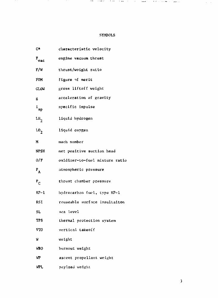
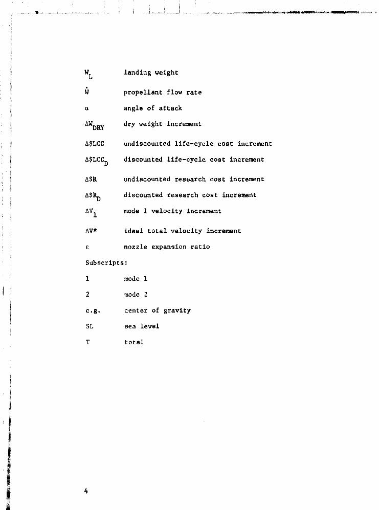
SYMBOLS
c* characteristic velocity
F engine vacuum thrust vac
F/w thrust/weight ratio
FOM figure ,f merit
GLOW gross liftoff weight
g acceleration of gravity
I specific impulse sp
LHZ
liquid hydrogen
1.02
liquid oxy~en
M mach number
NPSH net positive suction head
o/F oxidizer-to-fuel mixture ratio
PA
atmospheric pressure
Pc thrust chamber pressure
RP-l hydrocarbon fuel, type RP-l
RSI reuseable surface insultaiton
SL sea level
TPS thermal protection system
VTO vertical takeoff
W weight
WHO burnout weight
WP ascent propellant weight
WPL payload w(!i~ht
J
I i rl
I I I
- _l>2
landing weight
• w propellant flow rate
a angle of attack
dry weight increment
MLCC undiscounted life-cycle cost increment
discounted life-cycle cost increment
MR undiscounted res~arch cost increment
discounted research cost increment
mode 1 velocity increment
6V* ideal total velocity increment
£ nozzle expansion ratio
Subscripts:
1 mode 1
2 mode 2
e.g. center of gravity
SL sea level
T total
4
n:ClINOLOGY BASE
The resl'arch study reported In refercnet' 1 identified t~chno10gy art~a'4 that havc a potential for cost and lwrfofmal\cc bcn~fits with hoth "normal" 3nd "Ilccell'rated" Rrowth. Tlw anticipated goals of the acccleratl'd R&T activitil's 1n e 19l1t .lrt';}S Wt're shown to have si~nificant potuntial payoffs. T1ll'Ml' an-as, described in fc[erenet"' 1. were as follows:
(1) Thermal protection system (TPS)
(2) Propellant tanks;
(3) Wing and fin structur~;
(4) Thrust structure;
(5) Subcoo1ed propellants;
(6) Suhsystem weights;
(7) Mlycclluncous structures;
(8) Integrat lOll tmgineering (including launch and flight operatiomt ) •
The goals for accelerated R6.T activities in those areas, combined with goals for normal growth in other areas of technology, wore used to lil'rive vl'hlc1e concupts for vertical takeoff (\''1'0) lUlU
horizonta t takeoff (11'1'0) modes (ref. l). Singlt.·-mode propulsion concepts WL'n' uSl',i, that Is, tIUlin pugiut.' prop~llal\ts wt.~re liquid oxygen 0.0.,) and liquid hydrogen (LH,,). Tht! \'1'0 vehicle concept
~ -developed \lndt'r thest;' ~ul<lclitws that :\ssunlt'd aliY/mct'd technology growth was used I1S a point of departure (<1 n'fercnco vohicle) for the present study to detl'rmlno the possiblt· a,Mitional advantages of dual-mode propulsion applications.
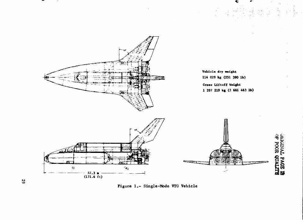
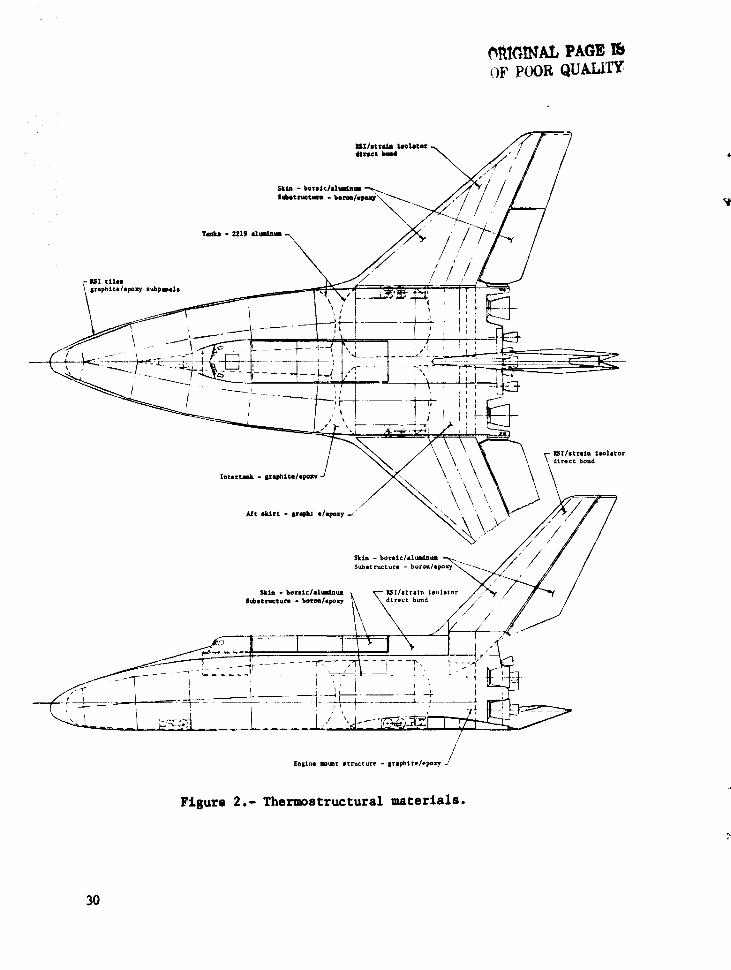
Thc sil\~te-mo,h' V1'O vl.'hicle is illustrated in figure 1, whereas its tn..'lll'rbls ,llld thermostructural featul'es ;~re ido1\tificd in f igurt' }.. Tid S vl'h ie It, ust'S load-carry ing, nluminwu, lntegr almembrane tanks (01- ,'arry Lng its to" dt\d Lit, main propellants. .. -Tlll' hydrl'gl'!\ ti\I\ktl ;l n' a 11\U It 11..,bt' dos ign \'ill'r,'as t \ It' ,'xy~el\ tanks are cyUndrkill. RcuHcablu surface insu1atlol\ (RSI) is used to thermally pr,'tect the \'ehicit' structurl'S Jurin~ aSclmt and lmlry (light. St.'v.'n main rockl·t l'I\~;il\etJ are used, three of which have two posit h'lls so tlll'Y can ol'l'ratl' at h1gh alt1tlldos with Il lar~ul'
~xpaLUlion rL1tlo than at !jca lovel. Some l'l'rfurmancc churacteritltics of tll('!H' t.·n~dlw9. cOllsidered to be of the SSME type with approved pcrf<1t'nutncl' obtailwd hy t\oL-mal tl'chllll1<>gy ~rowth and product devl,l,'pml'nt, art.' as ft,)llows:
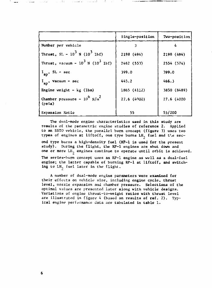
Single-position Two-position
Number per vehicle 3 4
Thrust. 3 51. - 10 N (10
3 1bf) 2198 (494) 2198 (494)
Thrust. vacuum - 103
N (103 1bf) 2462 (553) 2554 (574)
I sp' 5L - sec 399.0 399.0
I sp •
vacuum - sec 445.2 466.3
Engine weight - kg (lbm) 1865 (Ul2) 3850 (8489)
Chamber pressure - 106 N/mZ 27.6 (4000) 27.6 (4000 (psia)
Expansion Ratio 55 55/200
The dual-mode engine characteristics used in this study are results of the parametric engine studies of reference 2. Applied to an SSTO vehicle, the parallel burn concept (figure 3) uses two types of engines at liftoff. one type burns LH
Z fuel and tl-.~ sec-
ond type burns a high-density fuel (RP-1 is used for the present study). During the flight, the RP-1 engines are shut down and one or more LH2 engines continue to operate until orbit is achieved.
The series-burn concept uses an RP-1 engine as well as a dual-fuel engine; the latter capable of burning RP-1 at liftoff. and switching to LH1 fuel later in the flight.
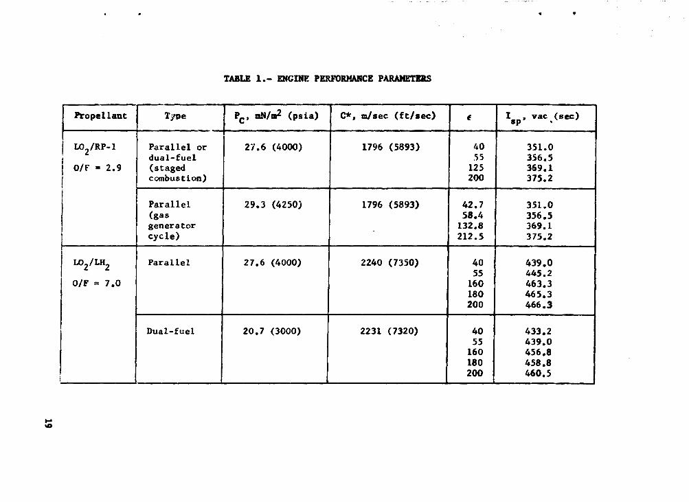
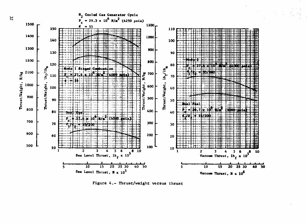
A number of dual-mode en~ine parameters were examined for their effects on vehicle size, including engine cycle. thrust level. nozzle expansion and chaml-er pressure. Selections of the optimal values are presented later along with vehicle designs. Variations of engine thrust-to-weight ratios with thrust level are illustrated in figure 4 (based on results of ref. 2). Typical engine perf0rmance Jata are tabulated in table 1.
6

VEHICLE ANALYSIS AND DESIGN
Approach
The potential benefits of dual-mode propulsion compared to all LOz/LH
Z single-mode propulsion were derived by examining
variations of vehicle parameters and design concepts leading to optimal, minimum dry-weight vehicles, and program costs. Design iterations were made using design layouts to establish bases for vehicle sizing, thermostructural loads and mass properties, together with flight perfornance analyses to establish mass ratio requirements and engine utilization strategies. The ascent strategies for optimal performance included use of two-position nozzles, engine throttling to 60% full throttle, sequential timephasing of mode 1 (RP-l) engine shutdowns, and gimbaled nozzles on mode 2 (LH
Z and dual-fuel) engines. The relative amount of
RP-l fuel to be consumed was varied to determine the near-optimal propellant loading fractions for each vehicle design.
Guidelines for design such as orrit requirements acceleration limits and aerodynamic performance ,",,,,\'e the same as reported in reference 1. For exampl~, ascent accelerations were limited to 3 g. The dual-mode vehicleo also use the same thermostructural concept as for the baseline, extended performance VTO vehicle. Variations in internal arrangement of subsystems, however, were made to maintain good 'rolumetric efficiency and minimum vehicle sizes.
Vehicle Design Parametrics
Variations of engine parameters were studied initially with a goal of achieving minimum vehicle weight. Of particular significance, the analyses showed the following features:
(1) Chamber pressures should be as high as practicable; the upper limits recommended in reference 2 were used, namely
LO/LII2 engine: 2
27.6 m N/m (4000 psia)
LO/RP-l engine: 2
27.6 m N/m (4000 psia)
Dual-fuel
cycle and
2 engine: 27.6 m N/m (4000 psia) for RP-l
2 20.7 m N/m (3000 psia) for LH2 cycle.
(2) Tradeoffs among ascent flight performance, specific impulse and nozzle weight lead to nozzle expansion ratios of 55 at sea level and 200 at altitude (similar results were shown in referernce 3). Packaging and geometric features of two-position
7
, , .
nozzles optimally should be determined in conjunction with the vehicle design. Nozzles are extended as soon as possible when the ambi~nt pressure during ascent becomes less than three times the nozzle exit pressure.
(3) For parallel burn, the RP-I engine (and vehicle) is better using a gas generator cycle with Llt., cooling than a staged .. combustion cycle. For series burn, the staged combustion cycle 18 desirable.
(4) Near-opt imal designs result when the nutnbers of mode 1 engines and mode 2 engines are the same. Vehicles with only mode I, dual-fuel engines are too heavy.
(5) For parallel burn. the L02/LH2 engine should have thrust
levels similar to SSM[ thrust levels to lower the engine DDT&E cnsts. For series burn. the RP-l and dual-fuel engines should have the same sea level thrust for lower DDT&E costs.
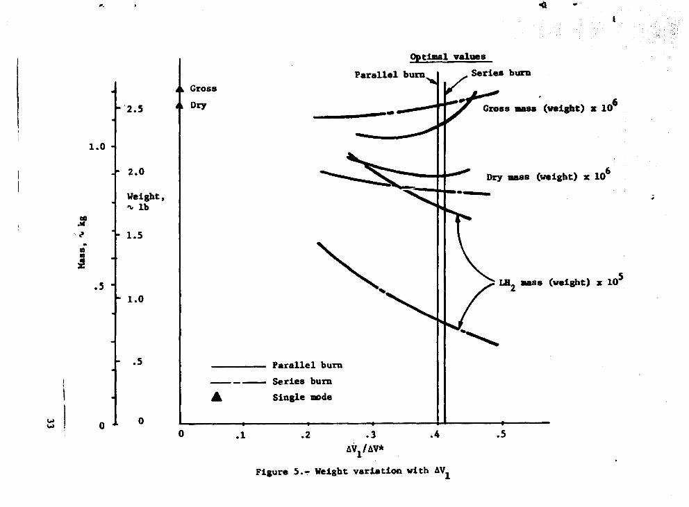
Typical vehicle weight variations are shown in figure 5 as functions of the mode 1 velocity increment ratio. Data are sho\,,-n for series and parallel burn vehicles. as well 3s for the reference single-mode vehicle (LIi
Z fllel). Increasing values of tJ.V
I correspond to increasing amounts of RP-I propellants consumed and used in the vehicle designs. The mass ratio requirements and tank volumes were. of course, varied as ilVl was varied. The
selected RP-l propellant weight yieldA near-minimum dry weight. The LH
Z weight is plotted in figure 5 because this fuel costs
20 times more than LO., or RP-l. It was determined. however. that .. mi~'mum program cost occurs for vehicles with near-minimum dry weight.
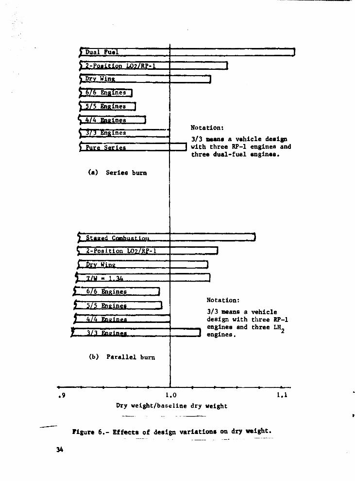
The results of vehicle resizing with variations of design featur'!s are summarized in figure 6. In addition to features previously discussed. these results indicate the following:
(1) I-lode 1 engines with two-position nozzles lead to heavier vehicles than with singit'-position nozzles;
(2) Hry wing designs. with no RP-l tanks in wil\~ or wing box areas. are heavier than wet wing designs;
(3) Minimum vehicle dry weIghts are '1chh'VeJ using a large number (12) of main engines. as a result of tht" 1l/w data of figure 4. C:O'lt rUllotidt·rtltion!'l. howp"','r. lpild to C;f'lf'd log tlp~l\!n'l
with ft."olt:r \·hj'.ln.· .. ;
(4) Liftoff accelerations of 1.2~ g arc ueLL~r Lluw 1.J4 g.
8
Vehicle Dasigns
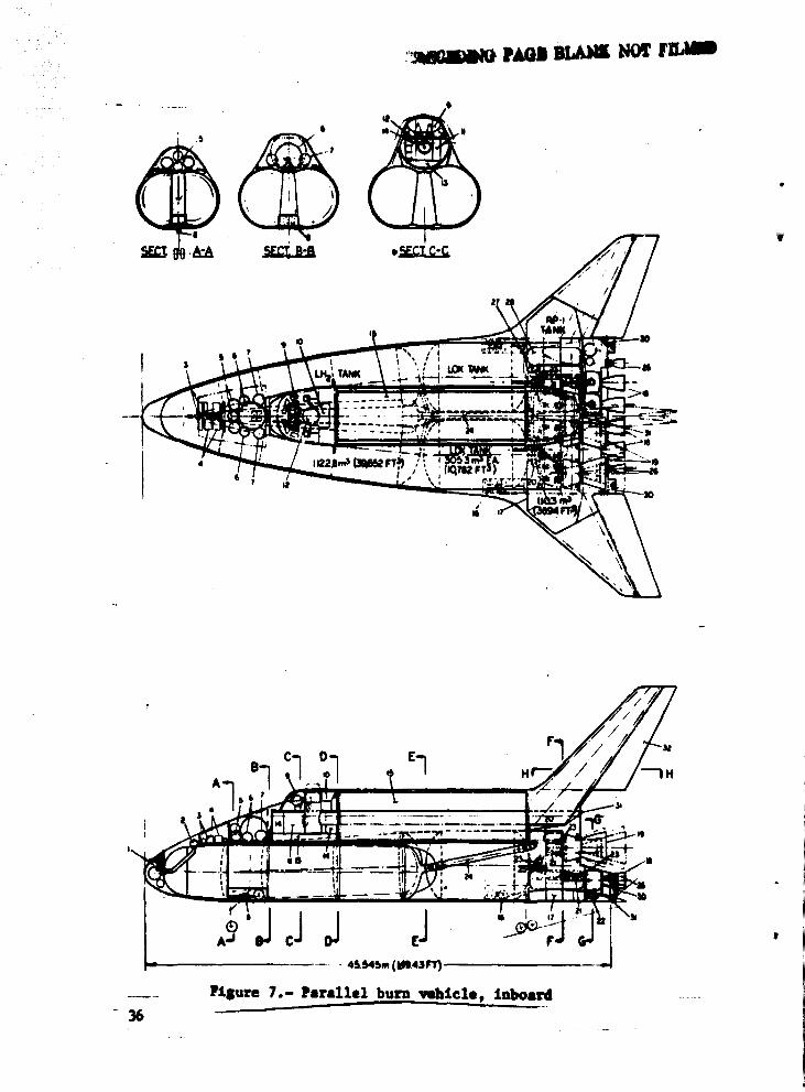
The dual-mode propulsion vehicle designs that result from the design iterations and parametric analyses are shown in figures 7 and 8. The parallel-burn vehicle (figure 7) uses four L02/RP-l
gas lenerator engines with four LOZ/LH2 engines. Vacuum thrust
levels are 1809 kN (407 klbf) ~d 2050 kN (461 klbf). respectively. for each RP-I and LH., engine. Whereas the LH? and LO? tanks arc . ~.
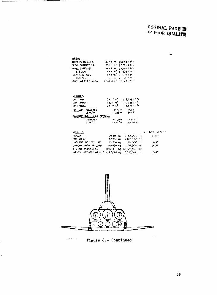
in the body, the RP-l is stored ira the central wing. This aP-l is pumped from the wing tank outlets to the lO'Jer engines. The OKS tanks are located above the wing box. The series-burn vehicle (figure 8) uses six staged-combustion engines; three are LO.,I .. RP-l eDlines and three are f\ual-fuel engines. For this vehicle. RP-l is stored both in t:,e wing and in tw.., body tanks nested aft of the LOZ tanks. The structural arrangements and load paths are
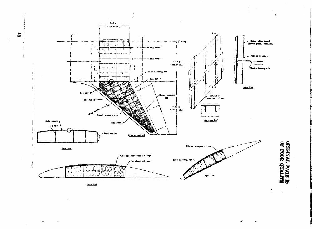
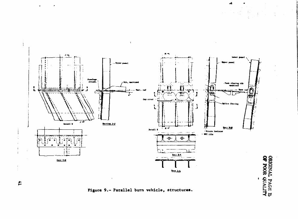
identical to those of the reference single-mode VIO vehicle. Thr wing splice {figure 9) is just outboard of the wing tank, providing for efficient assembly and leak tests of the t_ .. ~ section. Tht! composite wing skin structure is bonded to titanium fittings at the wing splice sections.
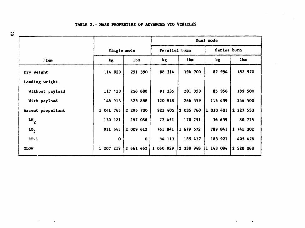
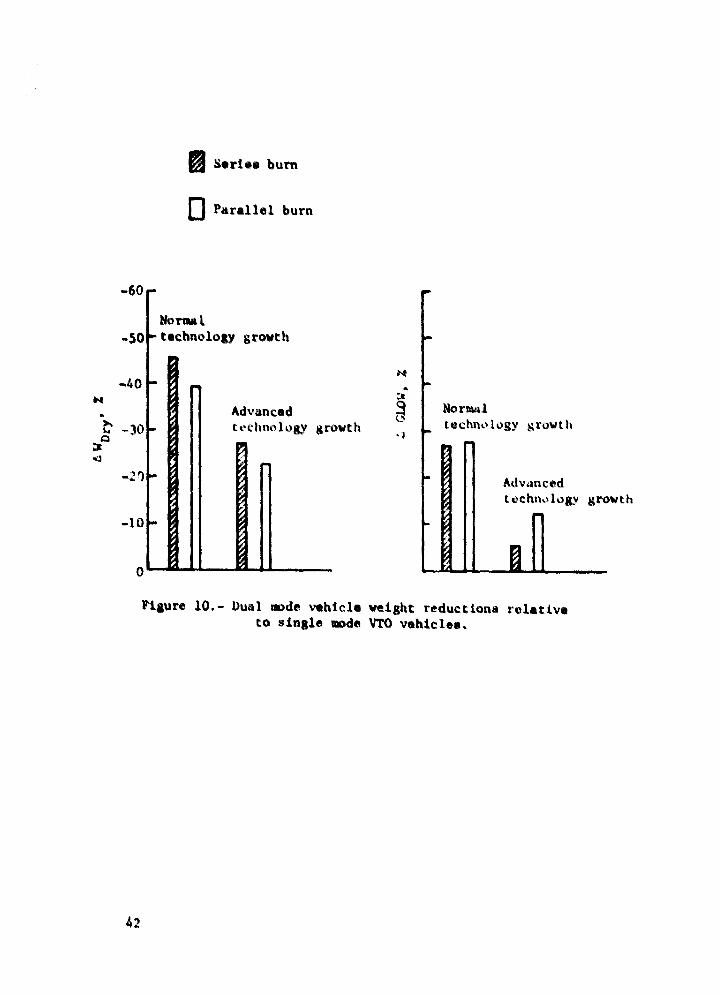
Summary mass properties of the vehicles are given in table 2. Figure 10 illustrates the percentage weight reductions that result from application of dual-mode propulsion. Both advanced technology and normal teChnology growth are used as bases for comparison. The relative weight advantages of dual-mode are more when ayrlied to the larger (normal technology growt~) vehicles.
9
LIFE CYCLE COStS
Approach
The life-cycle costs (LCC) were calculated using the same methods and ll.lsis as in reference 1, but with the addition of cost estimating rdations (CER) for the dual-mode engines. The cost model has as a basis the work breakdown struc".:ures, system development, s.:hedules t traffic models, and operations schedules consistent with SSTJ programs focused towards a 1995 lOG (initial operational capabilitj).
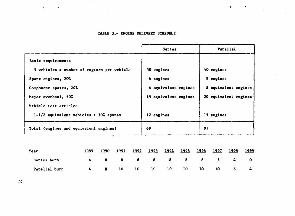
The schedule p~rmits • time span of up to 10 years for supporting research and technology (R&T) activities. The main engine DDT&! extends from 1983 through 1991, with manufacturing beginning in 1989. An engine delivery schedule is presented in table 3. Five vehicles are used in flight operations. ~ith 1,710 flights scheduled over a IS-year period after IOC.
Costs based on these schedules are presented in fiscal year 1976 dollars and in dollars discounted at a 10% annu41 rate. The costs include a 10% fce, and assume cost per pound of propellants as $1.00 for LH"J' $0.02 for LO." and $0.06 for RP-l. - ~
10
_____ -... ...... _~~ .......... ~"[. .b~.~-~· ....... _"" .. _ ... · --.--------------------....... -. ...... ~ ... .
ED,t ... type
L02
/LH2
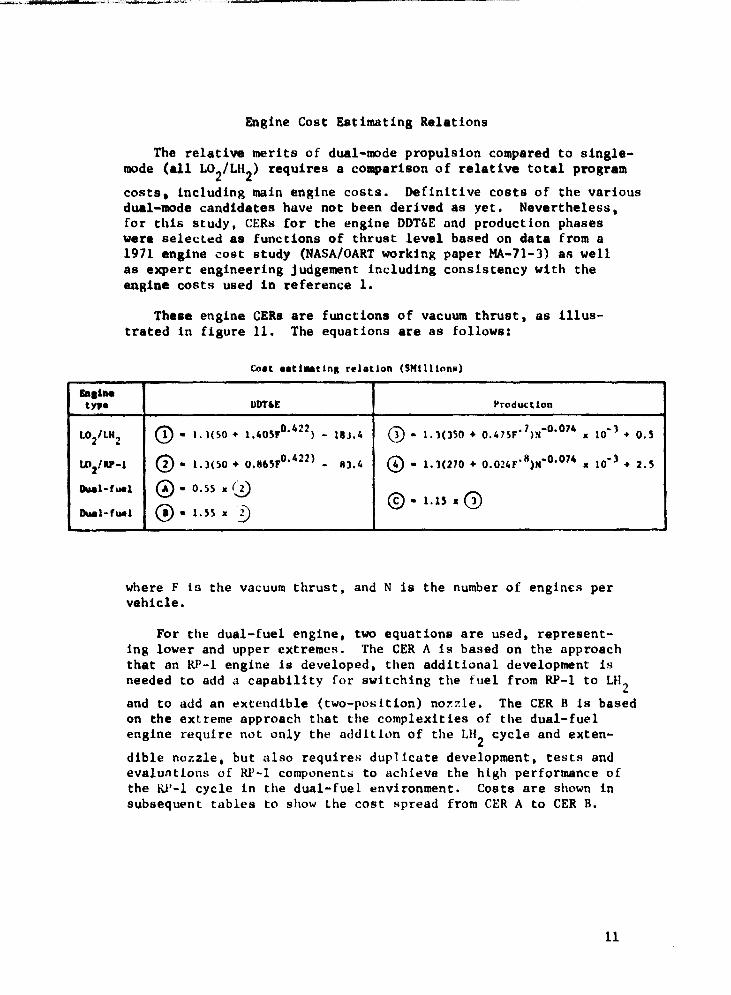
Engine Cost Estimating Relations
The relative merits of dual-mode propulsion compared to singlemode (all L0
2/LH
2) requires a comparison of relative total program
costs. including main engine costs. Definitive costs of the various dual-mode candidates have not been derived as yet. Nevertheless, for this stuJy. CERs for the engine DDT&E and production phases were selected as functions of thrust level based on data from a 1911 engine cost study (NASA/OART working paper MA-71-3) aR well as expert engineering judgement including consistency with the engine costs used in reference 1.
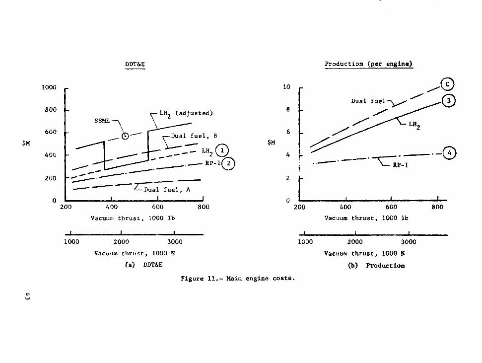
These engine CERs are functions of vacuum thrust, as illustrated 1n figure 11. The equations are as follows:
eoat aati .. tlna relation ($Mllltona)
DDnE Production
0 .. 1.1(S0 + 1.40srO.422 ) - 18J.4 0)- 1.1(1S0 + 0.47SF·1)N-O.074 • 10-3 + 0.5
L02/11P-l 0- 1.)(50 + 0.865Fo. 422 ) - 113.4 @oo 1.1(270 + 0.024F·8)N-O.074 • 10-3 + 2.S
Dlaal-f&tal 0 .. 0.55 • Q) (§) • 1.1S • ~ hal-flMl 0 .. l.S5 ·-D
where F 15 the vacuum thrust. and N is the number of engin€s per vehicle.
For the dual-fuel engine, two equations are used, representing lower and upper extremes. The CER A is based on the approach that an RP-I engine is developed, then additional development is needed to add a capability for switching the fuel from RP-I to LH2
and to add an extendible (two-position) nozzle. The CER B is based on the extreme approach that the complexities of the dual-fuel engine require not only the addition of the LH2 cycle and exten-
dible nozzle, but also requires duplicate development, tests and evalUAtions of RP-I components to achieve the high performance of the RP-l cycle in the dual-fuel environment. Costs are shown in subsequent tables to show the cost spread from CER A to CER B.
11
Figure 11 shows a point representing the DDT&E costi currently quoted for the main engine now being developed for the Space Shuttle (SSME - Space Shuttle Main Engine. F - 2090 kN. 470 klbf). A eER curve has been drawn through this point parallel to curve 1. The level of CER 1 was s~lected with considerations that
a L02/LH2 engine for SSTO would c~st less to dev~lop than the
SSM! engine inasmuch as the S5TO hydrogen engine would be similar to the SSME in thrust level and desIgn. and also -",ould have the technology growth associated with normal research.ld SSME roduct improvements over the next 10 years. If the S5TO were to use hydrogen engines with thrust levels more than 20%. say. from SSM! thrust levels. the advantages of the similarity to SSME could not be realized. Th~ DDT&E costs then would more nearly be represented by the CER that passes through the SSME point. The CER for LO/LIl2 engines is therefore chosen. as shown in figure
11, with a discontinuity where the thrust is 20% from the SSME thrust. ~he incre~ntal cost at the discontinuity is $260 million. For the dual-fuel engines. also. where the hydrogen vacuum t ust deviates more than 20T from that of the SSME. an increment of $185 million was added to CERs A and B. These incremental values were only applied in the cost analysis to select the numbers of engines for the series-burn and parallel-burn vehicles. If these increments were as small as 10% ($40 million), the selected numbers would not change. demonstrating that the discontinuity ~ssumed here is not affecting our gen-eral decisions and conclusions.
SSTO Program Costs
The life-cycle costs are summarized in table 4 for the single-mode and dual-mode vehicles. The spread in DDT&E costs rel<lte to the two dual-fuel engine CERa described previously. The progra'n costs are less for vehicles with dual-mode than with single-mode propulsion. with savings at least $435 million up to $812 million, with a maximum percentage ~av!ngs of 8.4%. Total costs for the series-burn and parallel-burn vehicles are within 4.2%, indicating that the Lee is not a strong driver in selecting among these two modes.
Table 5 shows costs for selected items. The DDT&E costs for engines are about 12% of those for the vehicle and other support. Engine production and spares costs are about 13% more for parallel burn. whereas LH2 costs are more than twice as much. Variations
of cost with numbers of engines were calculated that indicated lowest Lees wh~n t~t~C RP-l and three dual-fuel engines were used for the series vo.!l-.ld.e, and four RP-l and four LH') engtneM were used for the paral1~1 vehicle. ~
12
•
Other perturbations on SSTO dual-mode design parameters and cost were studied. All perturbations showed cost variations of less than 6% from the LCCs for the reference vehicles •
ADVANCED TECHNOLOGY RESEARCH PROGRAMS
In reference 1. twelve major R&T programs were identified as having good potential cost and performance benefits for application to SSTO program requirements. These programs, identified by title in table 6, were described (ref. 1) together with associated estimates of R&T funding and scheduling. These advanced programs are considered to require accelerated funding above the normal f\\ftding now projel.:ted to be allocated in these area. In the context of this study, dual-mode propulsion requires accelerated R&T focusing. and is part of the main engine technology area (programs 6. 7. and 8 of table 6).
Accelerated dual-mode propulSion R&T activities are required to achieve the engine performance and weight goals of reference 2 and used in this report for vehicle design and technology assessments. Objectives of these R&T programs are summarized as follows.
Main Engine Injectors/Chambers/Nozzles
Objectives: Improve high-pressure L02'RP-I engine technology
through intensive research of candidate components that may comprise the thrust chamber assembly. For dual-fuel engines, additional effort is required to ensure performance and hardware configuration compatibility with both RP-l and LH2 fuel.
~~in Engine Pumps
Objectives: Determ4ne pump design characteristics to achieve 2 high (approximately 27.6 mN'm , 4000 psia) chamber pressures for
L02 and RP-l propellants. Gosls include increasing efficiencies
and life and reducing weight.
13
Main Engine Cooling
Objectives: Improve coolin. techniques by performance improvement and weight reductions of chamber. nozzle, and turbine cooling components. With parallel burnt improved LH2 cooling
at hiah chamber pressures is required using the gas generator cycle for RP-l enainas. With series burn usina dual-fuel enaines, rea.arch for reaenerative L02 cooling is required.
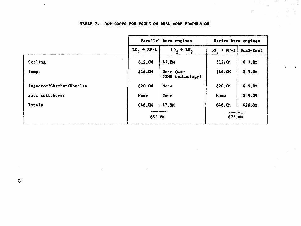
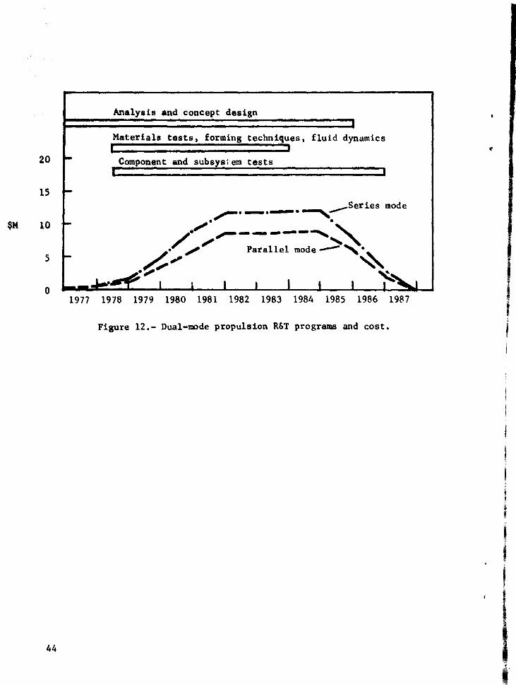
Batiaated costs for dual-mode advanced technOlogy programs are shown in table 7. The annual funding levels for these R&T costs are shown in figure 11 (fiscal year 1976 dollars). A substantial amount of this research needs to be completed by 1984 to provide the required R&T base for the DDT&E activities that are under way then.
HERIT ASSESSMENTS OF DUAL-MODE PROPULSION
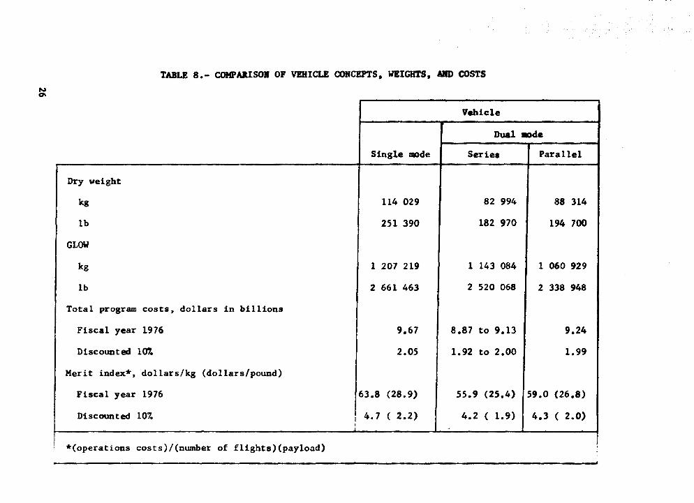
Various figures of merit (FOM) have been defined to help assess the relative cost nnd performance benefits of technology for SSTO applications. Imvortant comparative parameters include mass properties and costs (a.g •• table 8), research costs (fig. 12), and Lee savings per R&T cost (~$LCC/~$R).
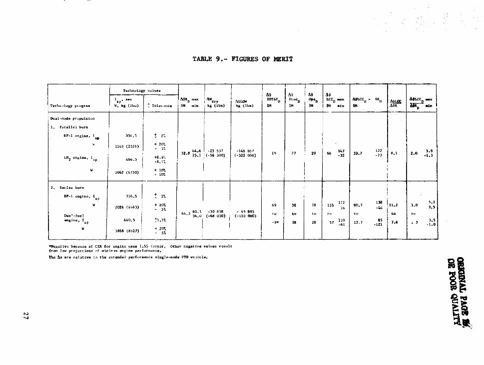
A set of FOMs is presented in table 9 for the dual-mode propulsion technology area, referenced to the extended performance, single-mode VTO vehicle. The estimated upper and lower limits of I and engine weight, taken as 95% confidence sp limits, were applied to vehicle resizing and program recosting. These data then, together with maximum and minimum estimates of R&T costs, yield the maximum/minimum values of FOMs for comparison with the expected values. As discussed later. the dual-mode FOMs have values that show this teChnology area has good potential cost and performance benefits compared to many other technolosy areas listed in table 6.
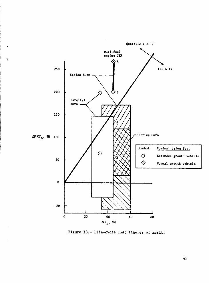
Fisure 13 shows the LCC savings as function of R&T cost for expected values as well as maximum and minimum values of the parameters. The percentage variations in R&T costs for dual-mode propulsion were assumed to be the same as for single-mode propulsion (ref. 1). The dashed line is reproduced from the results of reference I, dividing the technOlogy areas with FOMs in the upper quartiles from those in the lower quartiles. Data near this line, or above it. indicate good potential FOMs, as the dualmode propulsion exhibits here. Data are also shown for the merit of dual-mode applied to vehicles with normal technology goals used in other than the dual-mode propulsion technology area.
14

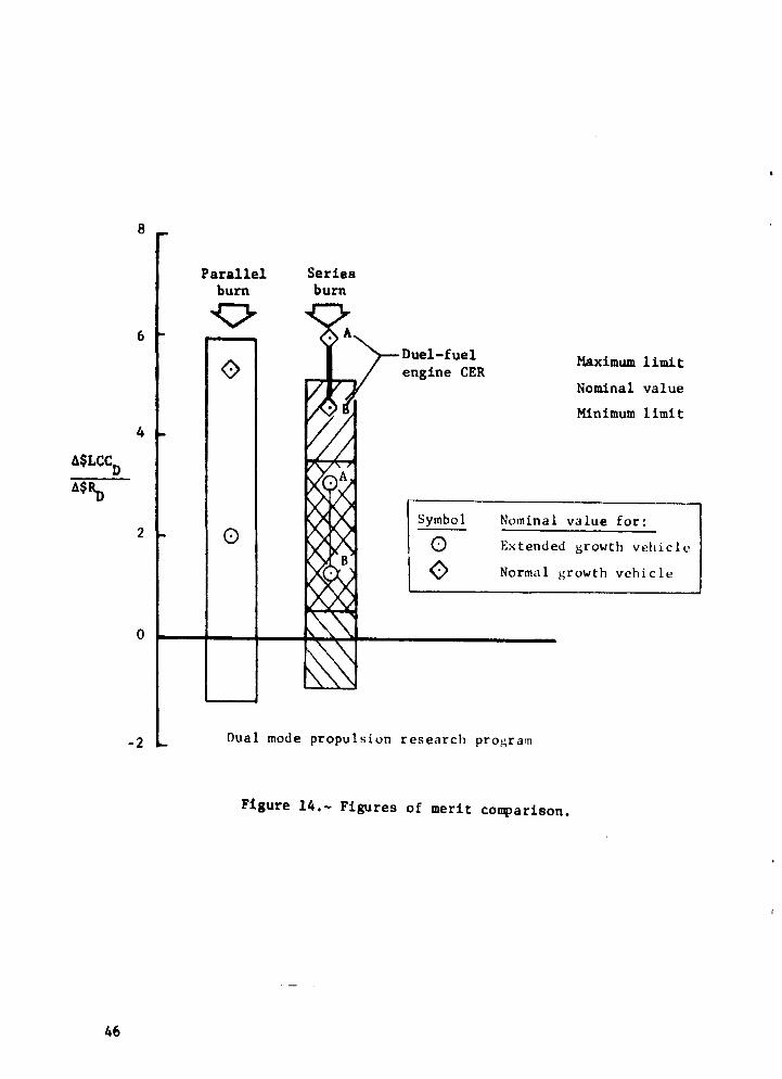
Figure 14 shows the ~$LCCD/6$~ POM, the program cost sav
ings per research cost required to meet the technology goals of dual-mode propulsion. Here, as in figure 13, the FOMs show significant potential benefits for dual-mode; these benefits are larger When dual-mode i~ applied to vehicles with other normal growth rather than advanced growth. Again, the relative merits of parallel burn and series b~rn are about the same, but are somewhat dependent on the CER (A or B) selected for the dualfuel engine DDT&E.
These FOMs rank in the Quartiles I and II of reference 1. indicating that dual-mod~ rropulslon has a potential high yield. It is exceeded 1n rank only by the technology areas entitled 1ntegration engineerina, miscellaneous structures, and wing and vertical tail structures.
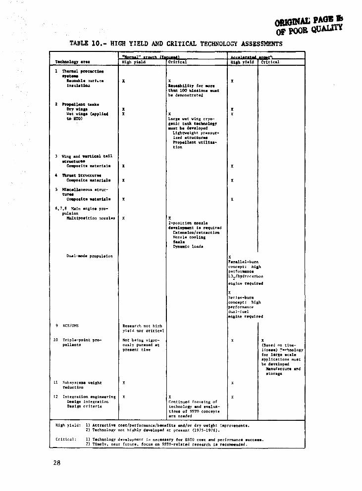
A tabulation of high yield and critical technology was presented in reference 1. This table 1s repeated here (table 10) but with the addition of dual-mode propulSion technology. This area is considered to be in the category of accelerated growth, as it requires additional fOCUSing of activities and funding beyond normal expectations. It is a high yield area because ~he present study has shown significant cost and performance benefits can be achieved through application of dual-mode propulsion to 5STO vehicles.
CONCLUSIONS
A fundamental goal of this study of dual-mode propulSion was to identify its potential cost/performance benefits applied to future earth-orbit transportation systems with vertical takeoff and horizontal landings. These systems used completely reusable, sinale-stage-to-orbit (SSTO) vehicles and had mission requirements similar to Spaco Shuttle. which the 5STO would replace in 1995. Both parallel-burn and series-burn propulsion concepts using RP-l and LH2 fuels were analyzed. based on engine characteristics de-
fined by another current NASA-sponsored study.
The benefits of dual-mode propulsion were identified by parametric analyses of its impacts on vehicle size and program costs, and by aefinlng specific vehicle characteristics for nearoptimum designs based on minimum weight and cost considerations. Figures of merit were used to asseSs the potential of the dualmode propulaion conceptB and their relations to single-mode systems.
15
The major results of the study are as follows:
(1) Sinale-staae-to-orbit concepts have exceptionally worthwhile cost/performance merits as advanced earth-orbital transportation systems;
(2) The application of dual-mode propulsion concepts can significantly enhance the cost/performance benefits;
(3) The amount of enhancement using dual-mode depends on the levels of technology in other important areas (such as material, structures, surface insulation, and LH2 propulsion). The merit
of dual-JlDde propulsion is larger when applied with "normal" technology projections;
(4) Merit indicators of parallel burn vehicle concepts compared with series burn concepts were within 5%, showing a dr}' weight and hydrogen cost advantage for series burn. The lifecycle cost and life-cycle cost savinas per dollar of requi~ed research were about the same for both concepts. Within the guidelines and tolerances of this study, therefore, both show about the same merit and are beneficial compared to single-mode propulsion concepts;
(5) Areas of dual-mode propulsion technology that need to be pursued to realize the goals required for SSTO vehicles are as follows:
a) High chamber pressure, high efficiency hydrocargon engines;
b) Pumps for all propellants to achieve pressure and performance goals;
c) Cooling of chambers and nozzles with L02 and LH2 in
conjunction with radiation cooling techniques;
d) Nozzle extension with or without engine shutdown;
e) Dual-fuel engine switchover from hydrocarbon to hydrogen fuel, preferably without engine shutdown.
(These are in addition to those high-yield and critical technologies described in reference 1.)
(6) Inasmuch as dual-mode propulsion showed significant potential for cost savings, more near-term R&T effort i8 indicated to pursue better definitions of engine concepts, engine coats and dual-mode vehicle concepts;
16
•
•
(7) Reduction of operations costs is a major goal for costeffective advanced transportation systems. Dual-mode propulsion studies should therefore include analysis of relative costs of launch operations with various types of engines;
(8) Other engine concepts and high density fuels for applications to advanced transportation systems continue to be offered for potential assessment studies. These include, for example, linear engines, new dual-fuel concepts, and synthetic and methane fuels. Integration engineering is highly recommended as a continuing, accelerated program to assure focusing of these and other R&T activities towards technology areas with best cost! performance benefits.
17
REFERENCES
1. Anon: Research study t,r., ldenii[y TeehnoLo(IY Uequil'emcnts rU}' Advanced b'arth-Orbital Tronspol'tation Systems. NASA CR- 1977.
2. Anon: Advanced High Pl'eS8Ul'e l!:ngine Study. NASA CR-1977 •
3. Eldred, Charles H •• Rehder, John J., and Wilhite, Alan W.:
18
Nozzle Selection fOl' Optimized Single-Stage Shuttle8~ XXVII International Astronautical Congress, Anaheim. California, October 1976.
.... -.0
j
I 1
Propellant
L02,RP-l
OIF .,. 2.9
LOZ/LHZ
OIF - 1.0
Type
-Parallel or dual-fuel (staged combustion)
Parallel (gas generator cycle)
Parallel
Dual-fuel
TABLE 1.- ENGINE PERFORMANCE PAlWfETDS
Pc' mN/m2 (psia) C*, m/sec (ft/sec)
2i'.6 (4000) 1796 (5893)
29.3 (4250) 1796 (5893)
27.6 (4000) 2240 (1350)
20.1 (3000) 2231 (1320)
.. ..
f I ,vae (sec) 8p ,
40 351.0 55 356.5
125 369.1 200 315.2
42.7 351.0 58.4 356.5
132.8 369.1 212.5 375.2
40 439.0 55 445.2
160 463.3 180 46'.3 200 466.3
40 433.2 'S 439.0
160 456.8 180 458.8 200 460.'
...., o
Han
Dry weight
LaDdiog weight
Without payload
With payload
Ascent propellant
~ L02
RP-l
GLOW
TABLE 2. - MASS PJtOPDTIES or ADVAHCEJ) vro V2lIICLIS
Dual mode
Single mode Parallel burn Series burn
kg Ibm I kg Ibm kg lbm
114 029 251 390 88 314 194 100 82 994 182 970
117 410 258 888 91 335 201 359 85 956 189 500
146 91l 323 888 120 818 266 359 11.5 439 254 500
1 041 766 2 296 700 923 405 2 035 760 1 010 401 2 227 553
130 221 287 088 77 451 170 751 36 639 80 775
911 545 2 009 612 761 841 1 679 572 789 841 1 741 302
0 0 84 l1l 165 437 183 921 405 476
1 207 219 2 661 463 1 060 929 2 338 948 1 143 084 2 520 068
~
i
\ ~illi 'I
,1.,' III
~ ~: I·
I,
ii,
1'1';
!
" ,I I. I'
I!
to.) .....
•
TABLE 3.- ENGINE DELIVERY SCHEDULE
Series Parallel ,..--- -
Basic requirements
5 vehicles x number of engines per vehicle 30 engines 40 engines
Spare engines, 201. 6 engines 8 engines
Component spares. 20% 6 equivalent engines 8 equivalent engines
Major overhaul, 50% 15 equivalent engines 20 equivalent enginel
Vehicle test articles
1-1/2 equivalent vehicles + 30% spares 12 enginel 15 engines
Total (engines and equivalent engines) 69 91 I
~~ . ---------- - .. -~-.- --.~-------~
!!.!!. l2§.2 12.2.Q l22! 1992 .!lli .!!2! .!2ll 1m .!2!l .!.2.2! .!!22
Series burn 488 888 8 8 540
Parallel burn 4 8 10 10 10 10 10 10 10 5 4

N N
Cost Item
DDT&!
Production
Operations
Total
First Article Cost ~~~-... ----.. ------
TABLE 4. - LIFE CYCL.! COSTS
Single Hode Series Burn
FY '76 $M Discounted $M FY '76 $M Discounted $M
5336 15f'8 5106 1519 to to
5367 1597
1125 227 941 189
3216 239 2818 211
9677 f 2054 8865 1919 to to
9126 1997
283 ---- 239 ----
Parallel Burn
FY • 76 $M i
Discounted $M ! -I
5280 1569 I
988 200
2974 219
9242 1988
250 ----
I~ ~i
t t .'1' \!
II' II.
Iii'
Ii; :Ii
ill
,Iii;
r
'1' "
il
Ii
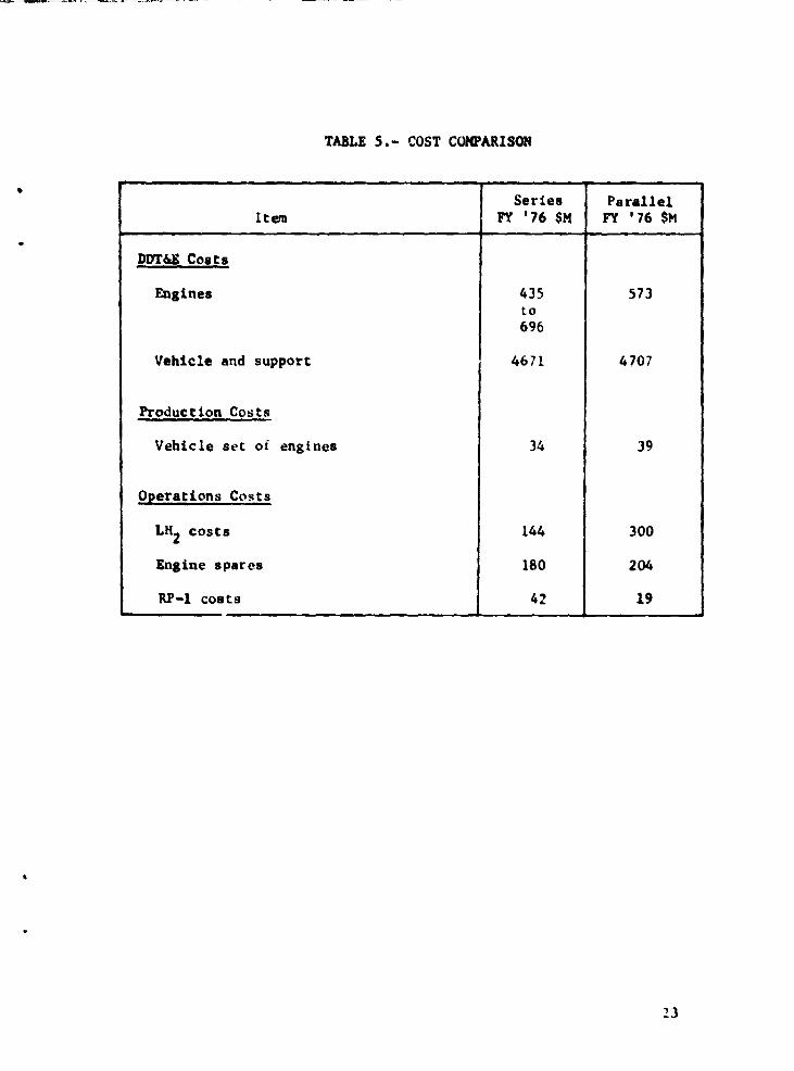
TABLE 5. - COST COMPARISON
Series Parallel Item FY '76 $K FY '76 $K
DDT&! Costs
Engines 435 573 to 696
Vehicle and support 4671 4707
Production Costs
Vehicle set of engines 34 39
Operations Costs
L~ costs 144 300
Engine spares 180 204
RP-l costs 42 19
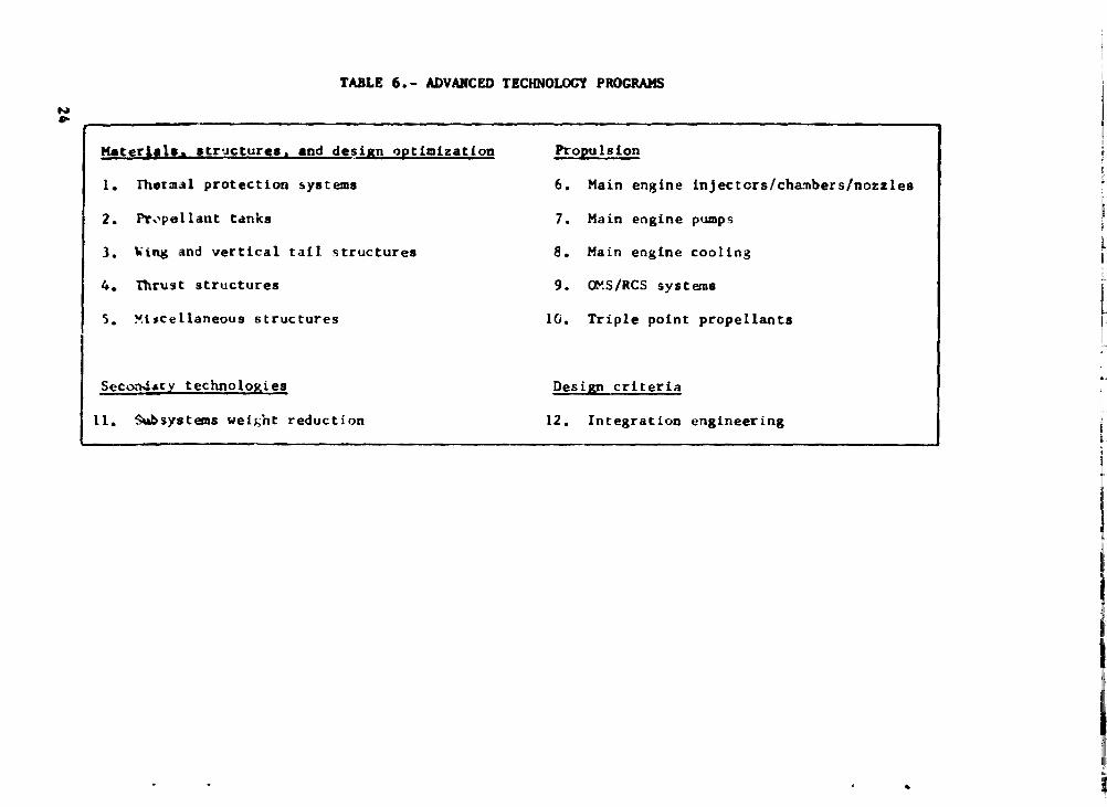
N • TABLE 6. - ADVANCED TECHNOLOGY PROGIWtS
Katerl,!,. ,tructures, and design QPtimization Propulsion
1. Thermal protection systems 6. Main engine tnj ectors/chambers/n.ozzles
2. Pr.·pella.nt tanks 7. Main engine pumps
1. ~'ng and vertical tail structures 8. Main engine cooling
4. Thrust structures 9. OXS/RCS .systems
5. ~t~cellaneous structures 10. Triple point propellants
SeconJ.ry technologies Design criteria
11. ~$ystems weihnt reduction 12, Integration engineering
..
l. Ii
~:"
II Ii'
Ii
,. Ii
ii L ..
I
:'1' "
'"Ii
Ii
II ilill
!n ••
I'1II 1111
to.) VI
TABLE 7. - R&T COSTS FOa POCUS ON DUAL-l«)DE PItOPULSIOI
Parallel burn englnes
L02 + RP-l L02 + LR2
Coe-Ung $l2.OM $7.8M
Pumps $l4.OM None (use SSHE technology)
Injector/Chamber/Nozzles $20.(10{ None
Fuel switchover None None
Totals $46.OM $7.8M --$S3.8M
'- ""--
Seriel burn englne.
L02 + RP-l Dual-fuel
$l2.(Jot $ 7.8M
$14.<11 $ S.OM
$20.<»f $ S.CII
None $ 9.CII
$46.OM $26 •• .--$72.8M
N Q\
TABLE 8. - COHPARISOII OF VEHICLE CONCEPTS. WEIGHTS, MfD COSTS
Vehicle
Dual.,d.
Single mode Series Parallel
Dry weight
kg 114 029 82 994 88 314
lb 251 390 182 970 194 700
GLOW
kg 1 207 219 1 143 084 1 060 929
lb 2 661 463 2 520 068 2 338 948
Total program costs. dollars in billions
Fiscal year 1976 9.67 8.87 to 9.13 9.24
Discounted lot 2.05 1.92 to 2.00 1.99
Merit index*, dollars/kg (dollars/pound)
Fiscal year 1976 63.8 (28.9) 55.9 (25.4) 59.0 (26.8)
Discounted 107- I 4.7 ( 2.2) 4.2 ( 1.9) 4.3 ( 2.0) I
*(operations costs)/(number of fllghts)(payload)
I
i
,
N ......
.. '
TABLE 9. - FIGURES OF MERIt
I Technology villues
'''''1 MRnm.x I AWdry Technology pr ogram W. kg (lbm) ! Tolerance $11 min I kg (Ibm)
Dual·mode propulsion
I 1. Parallel burn
RP-l engine, Isp 356.5
I -! 27,
W I 1145 (2524) + 20'7,
I - yr. 32.8 ~~:~ -25 537
(-j6 300) LH2 engine, lap 4&6.5 +l.9~'
-1. U
I W 3062 (6150) + L07. I
- 107.
I
I 2. Set'ies burn
RP-l engine. lap 356.5 + 2% -w + 20', I 2024 (4463)
"' 5% 60.31 -30 858
Dual-fuel 44.3 34.0 (-68 030) engine. lap 460.5 ~).I%
r j W 3868 (8527) +20%
- 5" "
"1fegative because {lof eEl. for engine uses 1.:>'; factor. Other negative ",a lues result from low projections of rnintmum engine performance.
The ~s are relative to the extended performance single-mode VTO Yt" .. l1cle,
"'--A$ M
,\GLOW DDr&~ ProdD
kg (Ibm) $11 $11
-146 057 (-322 000) 19 27
69 38
- 49 895 (-1l0 000) to to
-9· 38
A$ d$ Op"» LCeo .allt 4$LCCl) - $1t
D 4l!&!i ~LC'C!) .x $11 $11 IIln $11 4$1 ~ 111"
147 122 5.9 20 &6 -32 33.2 -17 8.1 2.0 -1.3
I !
I
28 172 138 , n.2 3.0
5.1 135 90.7 0.5 16 -44
to to to to to
28 57 119 12.7 85 7.6 i 3 3.5 -61 -121 -1.0
, -----
it ~:
~.
OIIGINAt .AQB ., or POOR QUALITY
TABLE 10.- HIGH YIELD AND CRITICAL TECHNOLOGY ASSESSMENTS
T..,1IIIo101Y area
1 Th"rmal prot .. tloa eyet_
"..uble .urh.". beulet1o.1
2 l'ropellaat tell'" Dry wtaa-
3
4
3
Ilet vb,_ (applied to HTO)
111111 &lid vert1eal taU .t~tUl""
Compocite matar1als
Thrust Struc:turu Composite .. t"rials
macellalleous struc-turea
Compostte .. teria!.
6,7.8 1!&1n ea,ine pro-pubion
Kultipoa1t1on "".d.s
Dual-mae propulsion
9 RCS/OMS
10 Trip1,,-point propellants
11 Subsyste .... "eight reduction
"II<>rmal" Itt"""" (t.ou.edl nab ylald Critical
x
x X
l
It
X
X
Research not high yield nor erit leal
II<>t being vigorously pursued at present time
x
X "u .. billey for more thlUl 100 111.&1011 ..... t b. d • ..,natrllteol
x Large vet ViDIl cryosente tank technololY _at b" .s"veloped
X
L1ghtwelabt preS8urized struc.tur •• Propellant IItUhation
2-posit1on Dazzle davelo_t is required
Lxten.lon/retraction lI<>.zl. cooling Suls Dynamic loed"
12 Intellration engineering X Design integration
X Continued focusing of technology and evaluation. of SSTO concept. are needed
Design criteria
X
High yield Critical
x
X X
X
X
x
Parallel-bum concept: hiah perfol1unce LJ/hyclrocarbon
eClline required
X Series-burn concept: high performance dual-fuel engine required
x X (Based on time-linus) "··""oloIY for larlle scale applications must be developed
Manufacture .nd .toras_
X
X
Hlah yield: 1) Attractive con/performance/benoUts and/or dry "eight improvemecu. 2) rechnolollY not highly developed at pr .. ent (1975-1976).
Critical: 1) Technology development is necessary for ssm cost and performance .ucc .... 2) Timely. near future, focus on SSTO-related research 1s recotmnended.
28
N \0
-
52.3 • (171.6 ft)
Figure 1.- Single-Mode VTO Vehicle
O(~1 ."
Vehicle dry wei.ht
114 029 kg (251 390 Ib)
Gross Liftoff Weilht
1 207 219 ka (2 661 463 Ib)
o c· "2:J :;:ti
"t1:::: 82 :;a~
£J§<:: ~ ~
"
30
Int.rtaDk - &raph1t.e/.,..,
asll.tt.tta bolatOf tI1 ... t_
/ AI, oUr, - Iraph1 '(apozr .. ./
SkiD - bortle/alumDUli Sl.lht\"\Ktofe .. borOll/e-poKY
SUn - bonle1dum.nua Sub.truc.ture - bOl'Olk/epoK)' - .......
Figure 2.- Thermostructural materials.
nn.tGINAL PAGE 1& OF P()()R QUALITY
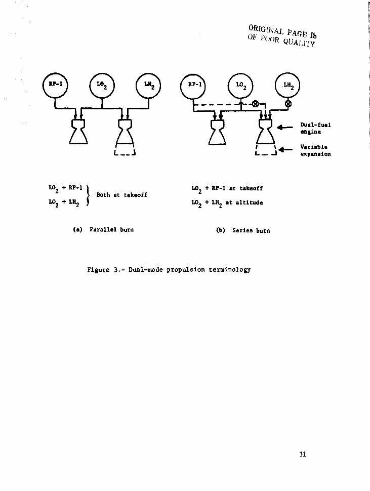
1.02 + RP·I } Both at takeoff
1.02+L~
(a) Parallel burn
1.02 + RP-I at takeoff
1.02 + L~ at altitude
(b) Series burn
Figure 3.- Dual-mode propulsion terminology
Dual-fuel engine
Variable expansion
31
I
1,..'1 N
1500
1400
1300
1200
110 1100 M ...... Z
.; 1000 ~ .. • ~ 900 ... 01 ::I ... t. 800
700
600
SOO
H2 Cooled Gae Generator Cycle
P - 29.3 x 10⁶ R,.2 (4250 pela) c
150 E noo
140
130
120 .JI ... ...... );' 110 ... .. ~ 100 .... u :II ...... ~ 90 e ·IS
ao
70
60
50
+-•. -+-i .... ".1""++-+-I.oI~~r.!~ttr:mt!mntW 1000
.. ~ 600 DO .... II :II ':;:; 500
01 :I ... IS 400
300
200
100
Sea Level Thrust. Ibf
x
I ,," .',
5 10 IS 20 25 30 40 50 Sea Level Thrust. M x 105
.l!J8 ... ...... ...
.I!J ... .. ... ~ .... .. ~ ... • e t;
110
100
90
80
70
60
so
40
30
20
! +
,-~ ..
HI '" t
.. .I... ' I' ',j, ',. :1 " ,I' !
I~'"
, ! , ,.' Hi, Ho+!+rt+++MI+++II!-"" ..... "r-DlLr.U.lU '""', .,. .t- .. II'
i_ -~ ~* : . " . f~ '"'' f+
1'" ,. r. ~~.l.. '. "
. !. ....' t~ , ~[I .!!' I" I ,!,~1 ~':,
t:i _tt.t::t-t1 .. r-t" .tttt,. 11 .. 1:1.,,, :ttffim,. ' f+ Hi Ii. tr ,,, - .. . hi ;l; pr:' ~- --F -,;,~j,J'~l""+" 'foe ..
." .~ "'l "', .. ~lj 1:+ ,.: :;" It~:;;:: .. , ":::: :;~ ,,- " "~-~ -~1rF:t i ' ~.~: . 11' :Ut ~~
"crr ,hlt I ~' ~i;; [' t· ., i;3 .;b 1+-1-"11--+" ,+ t.. .L. .' ,ri ; i:i~ ""t" r ,I I , .. :~Tl1I
,,- ~ ". t ..... "· '. f+! t ~+ 'fl.'ftil ;;;.'i. '~.'~~ ... " . r . ~" . + Itt ··':t~ i;::" ..
". t " .. + . J+t1* +i ;::: :~j , . T. ti .' , ":; .1' ':!il
, ,II' I I' ",I
10 1 2 3 4 5 6 S. 10 Vacuum Thrust, Ib
f .x 10
I 'I , , , t
5 10 IS 20 25 30 40 50
Vacuum Tbruet •• x 10'
Figure 4.- Thrust/weight versus thrust
~ ~
:: .~ .. • • :2
".
1.0
.5
o
2.5
2.0
Weight, '\. lb
r 1.5
1.0
.5
o o
Gross
Dry
• .1
0(1 ...
Optimal values
----............ ..
"" Parallel burn
Series burn
Single mode
.2 .3 A'll/AV*
.4
Fiaure 5.~ Weight variation with AV1
Series burn
Gro88 .... (veipt) x 10'
Dry 1D888 (weight) x 10'
--
LB2 mas8 (weiaht) x 105
.5
.9
-34
, Dual Puel
~ 2-Poaition L021RP-l " 't Dry Wina. . S 616 &talnes )
~ sjS:Engines ]
~ !il~ lkilinll
\ JIJ &tg1nes &
\ Pur@ S@ri@A
1
(a) Series burn
2:~~liGg ~gmD~i~igl' .. 2-Position L02/RP-l
i Dry WintZ
, T/v - 1 34 . ; 6/6 Engines '-
1 5l~ ~&in'l
1 414 F.nO'i n ...
I 3J:3 Enllin@s
(b) Parallel bum
I
]
Notation:
3/3 meana a vehicle design -I with three RP-l engines and
three dual-fuel engines.
1
I
1
I
J Notation:
t 3/3 means a vehicle design with three RP-l
I engines and three LH2 engines.
1.0 1.1
Dry weight/baseline dry weight
Fiaure 6.- Iffeeta of design variations on dry weight.
]"- -
I
t
•
t i
- 36 'iaure 7.- Parallal burn vehicla, inboard I
I
..... --------- . 4S,!I4SIII(II14.J'T}---------t
I] '"
t
, SECt o-Q
£:- l£t SEC! H-H
1
I. I . .. I. .. , . .. •• ' .. II .
". ". , .. " . ' .. n. ' .. It.
II.
" . n. n. ,.. D. N • u. II. D. ... II.
II.
\ '-
oRIGINAL PAG! • OF POOl. QUALRI '
.-"', ._ .. '" .. ",,,I"lA" ..... ," UU"'U4. ..... , •• , .... '". UU' ..... ''', ........ , '", uu _,LAllI, " .. ·,~.I ... _ .... , ""',A,I ........ " ... , -, .. / ...... "' .. ' It" ..... " •• ea ." ..... , .......... .... , .......... _1
IC," . "" ... H,.,tl ......... , •.. , .......... ",''' ~.,- , .... , .. , .. , '.11 .... ,_ • ,. ::rr.=,lr'''. , ..... , .•. n ....... "tI . • ,. :r,n~'r:.ml"· ....... ,. • • ttl •• U""" "" flllL'''' , .. 'UIL'.' .. ,-,-. _.LAIII ....... "" .... ,UIL' .. LIO ,_ "" __ " , ...
... , .. , ... , ... ,01, .• - .. ... -" ...... , .. • ...,. .. "ut fa.. \M,
_, _n'" , •• , ,JIll.,.., tI.tlU_U
",_'_00"" "'.11 _tI
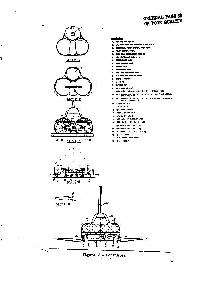
P1aure 7.- Continued 37

r I
... - ·l4l9O",\1I4!JO')
- - 2D43m(~,103')
~ . -JUWml1960') --------.
38
, , , .
"t • ' •
;: -~ . ./ : "
I 7411m(Y,1421 I r -
l(J( TANKS
, --~- .. ;
.. ~_ J
'\' ,: : " , . , .
- 42,74", (14().2Zl n ) ~ ... l""E~"",-,-T~:..:..._~ __
r l.~m (11.642';
I,m ... !4OU'!
--~T- r
~100 ... i (318Z!l"
,3 1I,3"'IKlll4')
i
4941"'(162 !<'H) ~-~ .• --- .. -----
'iaure 8.- Series burn vehicl •• layout.
.,
AALA) SOOI PI A" UE A WII'«'., TMWA"'h~A_
. WlM.~. E .. roSf :EI h'QIII
\I[I/'IC Ai. TA ••
'","U:,(I< PL1D- wtT'tV A~fA
V'~
kH. '.*'tA lfiT~ '1"-1 TANK!>
• '? • .../ :v.'~. H'l ,~! .. Pfl4~ 3.'''' fTll '41 iiI,.i I~i\~ rl~~} .1' PI ~l ~~ ~.fi'
!-' ~ ",I ~I'l ftll /' ,..,; \, ~t.,rt:'
j.~j4 4;?\l \ !4, 4~ r~~'
~"'-\, "~,,.' b~~0~\ ";)'1 Q ","
,'II.'~ n '\ ,::ry ,~ .. t~' d;.4;4 f ~ \,
"1\lI.lAD, ('tAMf TEA 4 !>';:- ... \ , .. f T I l[N{tfH ~ ~~ '" i bi..~r-r \
",,~,u:.w:~A~ ~~ i'lMIlf[R 4t~~'" j'~~ft i..[NI.~~lH !~ ~ .. , ~m ,tt.."""' ~tf\
*1. , ..... ;> PAn,lAt' ('4:. wt .... T
\ ,;\Nl • ....:~ ... _' r~ . ~_p '''''{'N.. WIT .. PllneAi' AS(('" I'q,'''£llAI\I' ,-AJSS LIt! Off .. -[~~
.'>, .... ' ~ ~:.- 'Q ~~ . ..¥'*'o ~
!!~.4.w tt.Q j,\."'I\"\"~l! ~
" • .',>it.' 'oQ
i ~.;,."': to! , 1~.:*.9f'\' i .. '
!~Q ~,-,'\ t'
,.~.!o.)(' .:-\':,,,~:;.~~_\ ito-j
.'.~.'I.,0hlI 'b'
Figure 8.- Continued
\)RI<1[NAL PAGE J8 'W PlloR QUAUT\1
39
40 , i I r---i I
• .!
~ I -
!~]il "
• --~~ <
1-'1
"---
--;
•
~ .. . I
'i • i i ..
1 i
l l
URIGINAL PA
GE J&
OF PO
OR Q
UA
LITI
.. .. • ... ... · · • • ! · ~
.. ! ~ .. !
, i
~ ~
j ... . !
! .. . I t
........ -: I . '-----
il :1 j: ! I / I I -'-1
, (J
" 0
-("
0"-0
-0
O---=-~:0 --
f) 0
f'
I)
o (,
0 ~-
0
(,
~-0
-, u
() f,
.:. 'In
(;
j -(,
f)
n -"
" f,
1------
" 0
0 rJ
"0'-(J
fjO
·0
~o-fJ
~"£.E
If---
\ \ I \ \)
I I
\ I ~
i '.
1 j
j
7 .. ! j • j
ORIG
INAL PAG
E Ib
OF PO
OR Q
UA
UT
Y
~. ~
.. :0
I i ! I'fl t
i I j 1 i
! I
'!
I \ '1
. ' I
iJl
,,...,--.1--
, ,,~-, _.
l:;,;-~~I· : • ___ J I, ••
: ~-~-----:
! ••
I .
~,
-I--F:~·~J. I,. I,
•
: t. l
~--.... ,
'
-r--.--:~,..~:~;. I :
' __ .. f..--- il
. • .. ... ='
~ ~
g ... ~ • .. .. .... u .... .c ~ c: ... =' .0
.... .. .... .... C\I ... C\I
a:t.. I • 0
\
~ r. .... ra.
41
-60,..
I S.rto. burn
[] Parallel burn
Nor1lllt -SO 10- teehnololY growth
-40 i-
-10~
Advanced technology growth
N
.. :a 3 I..:'
oJ
.. ~
.. ,..
Non.at technology growth
Advanced technology growth
Figure 10.- Dual .ade vehicle weight reductions relative to sinale mode VTO vehicles.
42
$M
~ 1..0.1
1000
800
600
40()
200
a
DDT&E
SSME'0_ -- Dual fuel. B
'C,:::- LHZ (0
--- _RP-l@ _ . -" ........------- -
::::..::-. - - Goal fuel. A --200
1000
400 600
Vacuum thrust. 1000 lb
2000 3000
Vacuum thrust, 1000 N
(a) DDT&E
800
10
8
6
$M
4
2
o
I r
t 200
1_ .
...c'I;11 ..
Product1on (per en.gine)
. __ ._-.-~.- --0 RP·l
400 600 800
Vacuum thrust, 1000 Ib
1000 2000 3000
Vacuum thrust, 1000 N
(b) Production
Figure 11.- Main engine costs.
Analysis and concept design •
Materials tests, forming techniques, fluid dynamics
t · 20 - Component and subsysl-em tests
I 15 ~
$M 10
5
o
__ Series mode
"....-.--.~ ~. .
/. ,,------'" ~ b·"'''''' Parallel mOde>,~
~~~ ~ __ l ,. I 1 I I I I I I '-.t -
1971 1978 1979 1980 1981 1982 1983 1984 1985 1986 19B1
Figure 12.- Dual-mode propulsion R&T programs and cost.
44
I i ~
I i •
I i i.
I
I
I 1
I
250
200
150
4 LccD, $M 100
so
o
-50
o
Dual-fuel engine CD
·A
Sedes burn -,.~----tII
20 40
4~.$M
Quartile I & II
60
o o
80
Nominal value for:
Extended growth vehicle
Normal growth vehicle
Figure 13.- Life-cycle cost figures of merit.
45
8
Parallel Series burn burn
0 6
Duel-fuel Maximum limi t 0 engine CER Nominal value
Minimum limit 4
A$LCCD
A$~
Symbol Nominal value for: 2 0 0 Extended growth vehicle
<> Normal growth vehicle
o
-2 Dual mode propulsion research program
Figure 14.- Figures of merit comparison.
46