n90-13428 - nasa · n90-13428 a gyroscope ... (fdf) will use to calibrate the iru from the ground...
TRANSCRIPT
N90-13428
A GYROSCOPE CALIBRATION ANALYSIS FOR THEGAMMA RAY OBSERVATORY (GRO)*
Eleanor A. Ketchum
Goddard Space Flight Center (GSFC)
Michael H. Lee
Computer Sciences Corporation (CSC)
ABSTRACT
The attitude analysts of the Flight Dynamics Division (FDD) are responsi-
ble for calibrating, among other sensors, inertial reference units (IRU), a
crucial activity for accurate attitude determination. The IRU calibration
utility (IRUCAL) for the Gamma Ray Observatory (GRO) spacecraft,
based on an algorithm developed by P. Davenport, includes user-specified
weighting matrices for the measurements, for the a priori misalignments,
and for the a priori biases. By assigning "large" values to the appropriate
a priori weighting matrix elements, one can choose to adjust only the
biases, only the misalignments, or some combination of the two. Different
weight matrices produce vastly different biases and misalignments for the
same measurement.
Current documentation and software do not adequately address the calcu-
lation and use of the optimal weight matrices involved in calibrating the
IRU. This study investigates several facets of the GRO IRU calibration as
it relates to the bias and misalignment weighting matrices. The physical
meaning and use of the bias and misalignment weight matrices in IRU
calibration are examined. The relation of the weighting and the final bi-
ases, misalignments, and their corrections are pursued.
Ultimately, methods for determining reliable, realistic weighting matrices
to be used in the GRO IRUCAL utility are determined. Possible correla-
tions among observation uncertainties are also explored. For the undeter-
mined case where the maneuvers are insufficient to identify all calibration
parameters, the weighting matrices allow as much information as possibleto be extracted from the measurements. Finally, applicable simulated
flight data are used, incorporating the appropriate calibration maneuvers,to test the weighting matrices in the IRUCAL utility, and examine correla-
tion effects.
*This work was supported by the National Aeronautics and Space Administration (NASA)/GoddardSpace Flight Center (GSFC), Greenbelt, Maryland, under Contract NAS 5-31500.
PRECEDING PAGE BLANK NOT FILMED 237
https://ntrs.nasa.gov/search.jsp?R=19900004112 2018-09-12T15:19:35+00:00Z
1. INTRODUCTION
The gyro calibration process contains many subtleties. Data can be used and interpretedseveral ways; identical data can be processed through the same software yet could achievevastly different calibration results. A paper in the May 1988 Flight Mechanics and Estima-
tion Theory Symposium (Reference 1) investigates the gyroscope calibration for the
Hubble Space Telescope, using the same algorithm as the Gamma Ray Observatory(GRO) software. Last year's paper, by Davenport and Welter, examines the selection ofthe loss function weight matrix when more accurate attitude sensor information is avail-
able in pitch and yaw than roll; the study, however, ignores the use of a priori informa-tion, assigning a zero weight to that term in the loss equation. The GRO mission will not
encounter such situations during normal operations but could benefit from incorporatinga priori information into the gyro calibration effort. This paper examines the careful useof a priori gyro information and covariance in calibration for the GRO mission and alsoconsiders any implications for future missions.
The GRO mission will employ an inertial reference unit 0RU) consisting of three two-
degree-of-freedom gyros built by Teledyne Systems Company. This National Aeronautics
and Space Administration (NASA) standard IRU, DRIRU-II, has flown successfully onseveral missions, including the Solar Maximum Mission (SMM). Each gyro in the IRU
contains two orthogonal sensing axes and are oriented to provide redundant sensing abouteach of these axes. References 2 and 3 contain a more detailed description of the IRU.
The general method that the Flight Dynamics Facility (FDF) will use to calibrate the IRU
from the ground comes from the algorithm used by SMM. A period of fixed-inertialattitude will be followed by an attitude maneuver. A period of constant attitude will then
follow the maneuver. An attitude solution will be determined using fixed-head star tracker
(FHST) data for both periods of fixed attitude. Gyro data are collected and compared tothe attitude solution generated by the FI-ISTs. Biases, misalignments, and scale factorscan then be determined. The basic mathematics for gyro calibration is presented first as
background for the reader. Further documentation is referenced for a more thoroughdiscussion.
The search for a priori information begins with past missions. To anticipate the kinds ofbiases and misalignments GRO's IRU might experience during launch, past missions that
used and calibrated the DRIRU-II in flight were examined. Unfortunately, Landsat did not
fully calibrate its DRIRU-II because of the nature of the mission. SMM, however, used a
calibration scheme similar to GRO's; the information from SMM's harly mission could,therefore, be applied to the GRO effort. Unfortunately, some information is not available
from the SMM calibration effort, so workarounds were developed where possible. A com-plete plan is, therefore, offered in Section 7 of this study so that all information will be
available from GRO's early mission. These data can be analyzed for future launches to
help establish appropriate a priori information to be incorporated into IRU calibrationefforts for future missions.
During the GRO mission, flight dynamics analysts will be using the IRUCAL utility (partof the GRO Attitude Ground Support System (AGSS)) to process gyro data and calibrate
238

the IRU. In this utility, the user is given the option of including a priori information. The
user is also allowed to weigh this information as he/she chooses. IRUCAL is sensitive to
these weights, as identical information weighted differently results in dissimilar calibra-
tion results. Section 6 of this study explores this sensitivity by performing simulations.
The dynamic simulator will create gyro data that will be processed through the AGSS.
These processed data will then be put through simulations involving the IRUCAL, includ-
ing different a priori estimates and weights. Different weighting schemes will be incorpo-
rated, noting the sensitivity of the results to weighting changes.
The final portion of this study presents conclusions and recommendations. Unfortunately,
little is documented concerning past use of the DRIRU-II and in-flight calibration as far as
actual early mission data. Some data could, however, be deduced and incorporated intothe GRO IRU calibration effort. The study furnishes a detailed list and schedule of early
calibration activities. During GRO's launch it will prove crucial to keep track of various
information not only to test out new a priori weighting schemes but to provide critical
information for missions still in the planning stages.
2. GRO GYRO CALIBRATION ALGORITHM
This discussion of the GRO gyro calibration algorithm closely follows Reference 1, and an
alternate derivation can be found in Reference 4. The calibration algorithm for GRO
assumes that a three-vector R is output from the gyros, and the measured angular velocity
is given by
QM = GoR- Do (1)
where Go is the 3-by-3 scale factor/alignment matrix and Do is the drift-rate bias. The
algorithm determines a correction matrix M to Go and a correction to the bias, d.
Ideally, the true angular rate Q is found using the corrected alignment matrix G and bias
D via the following equations:
G = MGo (2a)
D=MDo+d (2b)
V2 = GR- D = MQM - d (2c)
Let m = M - I, for I the 3-by-3 identity matrix and define the difference between the
measured and true angular rate to by
to ---- _-_M - _-_ = -m QM + d (3)
The elements of m and d are the paramcters solved for in the calibration algorithm.
These parameters can be related to attitude solutions as determined through data fromsensors such as star trackers if gyro output data are available between attitude solutions.
239

Again following Reference 1, let attitude solutions at time t be denoted by Q(t) in quater.nion form. The quaternion time derivative is given by
Q'(t) = Q(t) q(f_/2) (4)
where q(12/2) is a quaternion with vector component 12/2 and scalar component zero.
Let Q be the quaternion representing the true rotation for a maneuver and QM be thequaternion representing the rotation as determined by the gyro output. The attitude error
quaternion _ Q expressing the rotation from the gyro-determined postmaneuver attitudeto the true postmaneuver attitude is given by
6Q = QM(Q_Q) Q_ = QQ_ (s)
Applying the chain ruleof differentiationto Equation (5)above gives
_Q' "" Q q (Q/2) Qm1 + Q q-I (QM/2) QmI
Noting that
q-I (QM/2) = q (- QM/2)
and using Equation (3) results in
(6)
_Q' = Q q (-co/2) Q_ (7)
Integrating Equation (7) over the maneuver gives
6Q- 1 = f Qq(-co/2) Qg/dt (8)
where 1, the identity quaternion, is the constant of integration. Let Qal and Qaz be the
reference quaternions at the beginning and end of the maneuver (for GRO, these comefrom the Fine Attitude Determination System (FADS)) so that
Q =
Similarly, define the gyro propagated quaternions QG1 and Qc2 so that
QM = Qc;ll Qc2
Equation (8)then becomes
(Q_,11 Qa2) (Q_;_ Q¢;1) - 1 : f Q q (-¢9/2) Q_ dt (9)
240

The first order, Q can be replaced by QM in Equation (9). When this substitution is
made, the integrand becomes the quaternion representation for the rotation of the vector
-to/2 from the spacecraft coordinates at time t to the premaneuver spacecraft coordi-
nates. Dropping the scalar portion of Equation (9) and substituting for Q gives
ifZ_ = _ Titodt(10)
where _ is the vector component of 6Q, Ti is the (time-dependent) matrix trans-
forming vectors to premaneuver spacecraft coordinates, and i is a subscript designating
maneuver number. By dropping the scalar part of Equation (9), an approximation is
made equating 1 to the cosine of the error rotation angle. Because of these approxima-
tions, the calibration algorithm is by nature an iterative process.
Least-squares techniques can be applied to Equation (10). Rewrite Equation (10) as
Z = Hx (11)
where Z is composed of the (assumed) n Z_ vectors for n maneuvers, and x is defined as
shown below:
Z = {Z_, Z_, ..., Z_} r (12a)
x = {m11, mt2, m13, 11121, m22, m23, m31, m32, m33, dl, d2, d3) (12b)
H is a 3n-by-12 matrix of the form
l - Y1 1H= i
I[I -- Yn
where each UI is a 3-by-9 matrix with components given by
(13)
1f (Tjk)I(QM)Idt(Uj.k,30-,))1=(14)
and each Y1 is a 3-by-3 matrix given by
if(Yjk)1 = _" (Tjk)1dt (15)
An observed value for Z derived from combination of Q's from the GRO FADS and the
gyro's and is assumed to be of the form
Zobs = H xt + v (16)
241

where xt contains the true bias and alignment parameters and v is the measurement error
in Zobs • The loss function J for the least-squares solution is chosen to be
1 (E T W E + (x - Xa)T Sa (x - Xa))J= _- (17)
where
E = Zobs - Hx (18)
W and S_ are symmetric nonncgative definiteweighting matrices, and xa is an a priori
estimate of x. x*, the least-squaressolutionfor x, isgiven by settingthe derivativeof theloss function with respect to x equal to zero,
0 = H a-w[Zob, - Hx*] - S.[x" - x,] (19)
or
Define
x * = {H T W H + Sa)-I [H T W Zob $ "I" S a Xa] (20)
¢_X -_ Xt - X *
and substitute Equation (16) into Equation (19) to give
6x = fliTWH + S.) -1[H TWv_ S,(xt - x,)]
Let
(21)
N = fllTWH + Sa}-I
Ifthe correlationbetween v and (xt - xa) isassumed to bc zero, the covariance for dxcan be written as
<dxdx r> = Nilia-W <vva-> WH + Sa <(xt - x,)(xt - Xa)a-> Sa}N
If the optimal weightings.
(22)
and
W - <vvT> -1 (23a)
Sa = < (x t _ Xa ) (X t _ Xa)T >-I (23b)
242
are used, Equation (22) reduces to
< 6x t_xT > = N (24)
3. CROSS-CORRELATION OF ERRORS
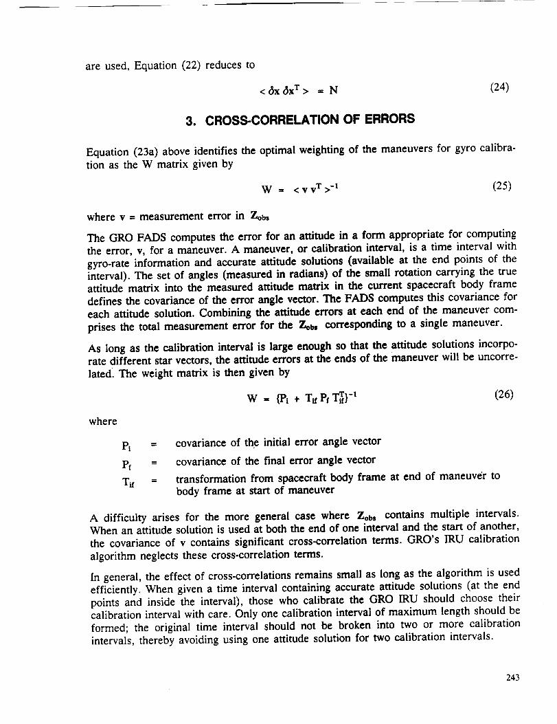
Equation (23a) above identifies the optimal weighting of the maneuvers for gyro calibra-
tion as the W matrix given by
W = <vv T>-I (25)
where v = measurement error in 7-,oh,
The GRO FADS computes the error for an attitude in a form appropriate for computing
the error, v, for a maneuver. A maneuver, or calibration interval, is a time interval with
gyro-rate information and accurate attitude solutions (available at the end points of the
interval). The set of angles (measured in radians) of the small rotation carrying the trueattitude matrix into the measured attitude matrix in the current spacecraft body frame
defines the covariance of the error angle vector. The FADS computes this covariance for
each attitude solution. Combining the attitude errors at each end of the maneuver com-
prises the total measurement error for the Zob= corresponding to a single maneuver.
As long as the calibration interval is large enough so that the attitude solutions incorpo-
rate different star vectors, the attitude errors at the ends of the maneuver will be uncorre-
lated. The weight matrix is then given by
W = {Pl + T_Pt T_} -1 (26)
where
t _--"
pf =
=
covariance of the initial error angle vector
covariance of the final error angle vector
transformation from spacecraft body frame at end of maneuver to
body frame at start of maneuver
A difficulty arises for the more general case where Zobs contains multiple intervals.When an attitude solution is used at both the end of one interval and the start of another,
the covariance of v contains significant cross-correlation terms. GRO's IRU calibration
algorithm neglects these cross-correlation terms.
In general, the effect of cross-correlations remains small as long as the algorithm is used
efficiently. When given a time interval containing accurate attitude solutions (at the end
points and inside the interval), those who calibrate the GRO IRU should choose their
calibration interval with care. Only one calibration interval of maximum length should be
formed; the original time interval should not be broken into two or more calibration
intervals, thereby avoiding using one attitude solution for two calibration intervals.
243

4. INFORMATION FROM PAST MISSIONS
The IRU calibration algorithm for GRO is capable of including the weighting of the a
priori estimates of the components of x. From Equation (23b), the optimal weightingmatrix associated with this a priori information is
Sa = < (xt - Xa)(X t - Xa) T >-1 (27)
Since the a priori values of x will always be zero, S= reduces to the inverse of the covari-
ance of xt. The following two scenarios for estimating S= are expected to occur duringGRO's mission, the first of which is the focus of this section:
• GRO's gyros will first be calibrated on the ground. Therefore, when GRO is first
deployed, the effects of the launch shock on the IRU will be the major contribu-
tor to the uncertainty in xt.
• Following the first calibration of the gyros, the a priori information becomes
simply the covariance of the 6x from the previous calibration (propagated to atime appropriate for the current calibration effort).
Due to the lack of rigorous analysis on launch shock effects, only a rough estimate of the
statistics of xt after launch is considered. For this reason, several simplifications are
incorporated. The first assumption is that the change in the alignment and bias for each
gyro channel from the ground calibration values to the first in-flight calibration is as-sumed to be a normal random variable with zero mean.
The value of xt depends on the error in the prelaunch calibration, the change due to
launch shock, and all other effects occurring before the first calibration in orbit. Alongwith the space environment, launch shock is assumed to be the dominant effect. The best
source of launch shock information should be past missions that also flew a DRIRU-II.Two missions have flown these IRUs: SMM and Landsat.
Unfortunately, because of the nature of its attitude during mission (constant 1 revolution
per orbit (RPO)), Landsat did not calibrate the misalignments, as GRO's algorithm must,
but depended solely on bias adjustments to meet accuracy requirements. Therefore, this
study relies on SMM as the prime source of information on gyro performance duringlaunch.
Following the development in Reference 5, gyro drift is neglected and an inertial frame is
defined as the body frame at the start of the maneuver. The equation
_"_inertial = R Mo f2M (28)
244
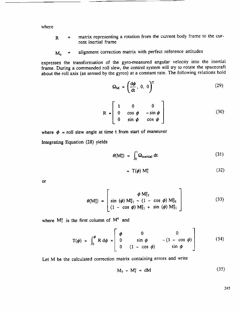
where
R ___ matrix representing a rotation from the current body frame to the cur-rent inertial frame
Mo = alignment correction matrix with perfect reference attitudes
expresses the transformation of the gyro-measured angular velocity into the inertial
frame. During a commanded roll slew, the control system will try to rotate the spacecraft
about the roll axis (as sensed by the gyros) at a constant rate. The following relations hold
00)T (29)
1 0 0 1R = 0 cos 0 - sin 0 (30)
0 sin 0 cos 0
where 0 = roll slew angle at time t from start of maneuver
Integrating Equation (28) yields
0(M_) = _-_inertial dt" (31)
= T(O ) M]
or
I 0 M_1O(M_) = sin (0) M_1 - (1 -
(1 - cos 0) M_I +
7cos 0) M_I /
sin (0) M_I Jwhere MS is the first column of M ° and
0
sin 0
(1 - cos 0)0 ]-(1 - cos 0)
sin 0
Let M be the calculated correction matrix containing errors and write
M1 - M_ = dM
(32)
(33)
(34)
(35)
245
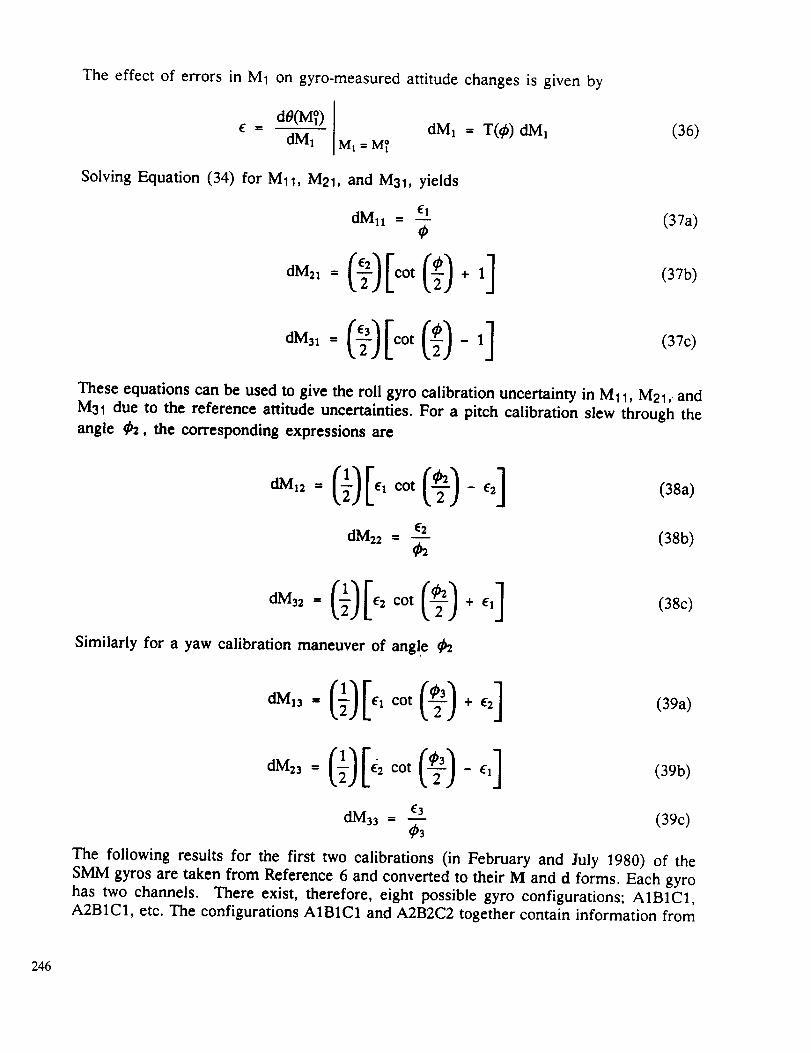
The effect of errors in M1 on gyro-measured attitude changes is given by
IdO(M_)[ dM1 = T(_) dM1 (36)
E = dM1 [ Ml = MT
Solving Equation (34) for Mll, M21, and M31, yields
dM11 = e--Z1 (37a)
(37b)
ot ,7c>These equations can be used to give the roll gyro calibration uncertainty in M11, M21, and
M31 due to the reference attitude uncertainties. For a pitch calibration slew through the
angle _b2, the corresponding expressions are
oot -,2] (38a)
dM22 = fi-E2 (38b)¢2
Similarly for a yaw calibration maneuver of angl e _2
(38c)
dM_3 = (1)IEzCOt(-_)+E2 ] (39a)
dM23 -- (1) IE2 cot (-_) - E'I1 (39b)
dM33 = f._3.3 (39c)¢3
The following results for the first two calibrations (in February and July 1980) of the
SMM gyros are taken from Reference 6 and converted to their M and d forms. Each gyro
has two channels. There exist, therefore, eight possible gyro configurations; AIB1C1,
A2B1C1, etc. The configurations AIBIC1 and A2B2C2 together contain information from
246
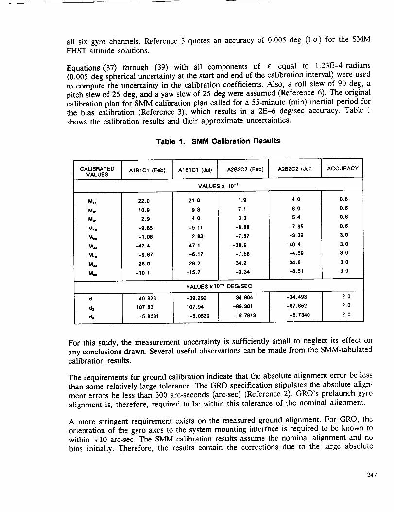
all six gyro channels. Reference 3 quotes an accuracy of 0.005 deg (1 a) for the SMM
FHST attitude solutions.
Equations (37) through (39) with all components of e equal to 1.23E-4 radians
(0.005 deg spherical uncertainty at the start and end of the calibration interval) were used
to compute the uncertainty in the calibration coefficients. Also, a roll slew of 90 deg, a
pitch slew of 25 deg, and a yaw slew of 25 deg were assumed (Reference 6). The original
calibration plan for SMM calibration plan called for a 55-minute (min) inertial period for
the bias calibration (Reference 3), which results in a 2E-6 deg/sec accuracy. Table 1
shows the calibration results and their approximate uncertainties.
Table 1. SMM Calibration Results
CALIBRATEDVALUES
A1B1C1 (Feb) A1B1C1 (Jul) A2B2C2 (Feb) A2B2C2 (dul} ACCURACY
VALUES x 10 -4
MI!
Mr1
Ms1
MIz
M,
M_,
M_
M_
M_
22.0
10.9
2.9
-9.65
-1,08
-47.4
-9.67
26.0
-10.1
21.0
9.8
4.0
-9.11
2.83
-47.1
-6.17
26.2
-15.7
1.g
7.1
3.3
-8.88
-7.67
-39.9
-7.58
34.2
-3.34
4.0
6.0
5.4
-7.85
-3.39
-40.4
-4.59
34.6
-8.51
0.8
0.6
0,6
0.6
3.0
3.0
3.0
3.0
3.0
VALUES x 10 -_ DEQ/SEC
dl
dz
d,
-40.828
107.80
-5,8081
-39.292
107.94
-6.0539
-34,904
-89.301
-6.7913
-34,493
-87.852
-6.7340
2.0
2.0
2.0
For this study, the measurement uncertainty is sufficiently small to neglect its effect on
any conclusions drawn. Several useful observations can be made from the SMM-tabulated
calibration results.
The requirements for ground calibration indicate that the absolute alignment error be less
than some relatively large tolerance. The GRO specification stipulates the absolute align-
ment errors be less than 300 arc-seconds (arc-sec) (Reference 2). GRO's prelaunch gyro
alignment is, therefore, required to be within this tolerance of the nominal alignment.
A more stringent requirement exists on the measured ground alignment. For GRO, the
orientation of the gyro axes to the system mounting interface is required to be known to
within 4-10 arc-sec. The SMM calibration results assume the nominal alignment and no
bias initially. Therefore, the results contain the corrections due to the large absolute
247

alignment errors. This correction can contain directional biases; the x-axis misalignmentis likely to be similar for both configurations.
The calibration results show a 0.91 sample correction between the A1B1C1 and A2B2C2
misalignment terms (M_j). The degree to which this effect is due to launch shock cannot
be determined without the measured values for the prelaunch misalignments, and unfortu-
nately, these results are no longer available. The sample mean and standard deviation
are -1.8 and 21 (x 10-4), respectively, for the A1B1C1 configuration and -2.3 and 19
(x 10 -4), respectively, for the A2B2C2 configuration. During the first calibration for the
GRO DRIRU-II, the SMM results indicate that for the correction made to the nominal
alignment matrix a zero mean can reasonably be assumed, and an uncertainty on the
order of 20 (x 10 -4) can be expected.
Although the Mii terms contain scale factor and misalignment effects, this estimation
treats the M_j identically. For the current analysis, no further effort seems worthwhile;
however, it should be noted that assuming that the Mij terms are normal variables allows
one to assign a confidence level of 90 percent to the assumption that the standard devia-
tion of the Mij for A1B1C1 is less than 34 (x 10 -4).
When the initial estimate of the GRO alignment is taken from the more accurate meas-
ured prelaunch alignments, a substantially lower variance in the alignment results can be
expected. Environmental testing performed on the DRIRU-II shows that the gyro uncer-
tainties due to any environmental effects are small compared to the absolute alignment
errors. The alignment shifts due to environmental tests of Reference 6 reflect a standard
deviation of 17 arc-see, with the absolute alignment errors producing a standard deviation
of 111 arc-see. A 17 arc-see change in alignment (first order) corresponds to roughly a
0.8 (x 10 -4 ) change in Mij (i not equal to j for alignment effects). The GRO requirement(Reference 5) is for alignment stability to within 20 arc-see.
Similarly, scale factor changes across the environmental testing were on the order of
120 parts per million (ppm) compared to absolute alignment errors on the order of
1300 ppm. The diagonal elements of M are roughly 1.2 (x 10 -4) for a 120 ppm change
in scale factor. Uncertainties comparable to this are on the order of the likely measure-
ment errors for GRO calibration, 0.008 deg 1 a attitude solution uncertainty.
For the gyro biases, the environmental tests showed results similar to the alignment data.
For the different test temperatures, the environmental change in the biases gave standard
deviations ranging from 4 to 8 (x 10 -6 deg/sec). The standard deviation for the bias itself
was on the order of 42 (x 10 -6 deg/sec). Again, the tested environmental stability was onthe order of the attitude solution uncertainties, with the total bias correction an order of
magnitude larger.
The following conclusions are drawn considering the a priori weighting matrix for the first
in-flight calibration of GRO. For nominal initial calibration alignments and biases, large
uncertainties (with respect to the expected measurement errors) should be assigned to thea priori estimates. The calibration algorithm will not be sensitive to the exact uncertain-
ties used in this case; values commensurate with the SMM values are appropriate. If the
248

ground-measured alignments and biases are assumed to be the initial values, uncertainties
that agree with the environmental stability requirements are probably appropriate. The
a priori alignments and biases will then be weighted roughly equally to the in-flight meas-
urements. Without access to the ground measured alignments and biases for SMM, as-
suming such small uncertainty due to launch shock, seems presumptuous. For GRO,
however, maneuvers sufficient to determine the alignment/scale factor matrices and bi-
ases are planned. It is suggested that both approaches be implemented as well as a third
approach using the ground-measured alignments and biases and applying large a priori
uncertainties. The results for all three approaches should then be analyzed for consis-
tency.
5. PROPAGATION OF COVARIANCE MATRIX
As noted previously, a method is needed to propagate the covariance matrix of the cali-
bration solution x. After the first planned set of maneuvers for GRO, it is likely that only
partial information will be available for subsequent calibration updates. In this situation,
the GRO algorithm operates optimally if the a priori uncertainties are known.
Immediately after the first in-flight calibration, the covariance of the solved-for biases and
misalignments can be computed. The uncertainty in the solved-for values then increaseswith time. The random walk acts as the standard model to describe the time variation of
the estimated state vector (for gyro calibration, the 12 vector of the misalignment terms
Mij and the bias vector corrections).
For the DRIRU-II, random walk type modeling is used for the short term (roughly
6 hours). However, this type of modeling is not appropriate for the DRIRU-II's long-term
behavior. The misalignment and bias corrections appear to be bounded in the long term
as opposed to the unbounded behavior of the random walk processes. Reference 7 reports
the ground measured 74-month stability value for the serial number 1001 DR/RU-II to be
7.9 arc-see. The 74-month stability of its scale factor was 58-ppm (dropping the data for
the "c" channel due to electronic module changes) and the 66-month stability for the
serial number 1004 was 77 ppm. The absolute changes in the gyro biases for these two
cases were 0.005 and 0.009 deg/h.our, respectively.
Numbers commensurate with these can be used to give conservative estimates of the
increase in the state vector corresponding to times of several months or more if the in-
flight calibrations results support them. The noise processes leading to the increases in
the state vector uncertainty are assumed to be independent. Therefore, only the diagonal
terms of the covariance would increase.
The SMM values for misalignment angles can be approximated (in radians to first order)
by the off-diagonal values of M. The scale factors (SFi) resulting from the in-flight cali-
brations can be computed from the resultant alignment matrix and are displayed in
Table 2.
The measurement accuracies are approximately 80 ppm for SF1 and 300 ppm for SF2
and SF3. The error propagation effects are on the order of the measurement noise so that
249
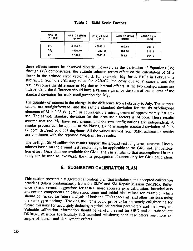
Table 2. SMM Scale Factors
SCALEFACTOR
SFI
SF=
SF=
A1B1C1 (Feb)(ppm)
-2195.6
-598.40
1706.4
A1B1C1 (Jul)(ppm)
-2096.1
-727.45
2008.5
A2B2C2 (Feb)(pprn)
189.84
404.31
683.8
A2B2C2 (Jul)(pprn}
399.9
212.3
964.5
these effects cannot be observed directly. However, as the derivation of Equations (35)through (42) demonstrates, the attitude solution errors effect on the calculation of M is
linear in the attitude error vector e. If, for example, Mij for A1B1C1 in February is
subtracted from the February value for A2B2C2, the error due to e cancels, and the
result becomes the difference in Mij due to internal effects. If the two configurations are
independent, the difference should have a variance given by the sum of the squares of the
standard deviation for each configuration for Mij.
The quantity of interest is the change in the difference from February to July. The compu-
tations are straightforward, and the sample standard deviation for the six off-diagonal
elements of M is 0.38 (x 10 -4) or equivalently a misalignment of approximately 7.8 arc-
sec. The sample standard deviation for the three scale factors is 74 ppm. These results
assume that the Mij have zero means, and the two configurations are independent. A
similar process can be applied to the biases, giving a sample standard deviation of 0.78
(x 10 -6 deg/sec) or 0.003 deg/hour. All the values derived from SMM calibration results
are consistent with the reported long-term test results.
The in-flight SMM calibration results support the ground test long-term outcome. Uncer-
tainties based on the ground test results might be applicable to the GRO in-flight calibra-
tion effort. Once data are available for GRO, analysis similar to that accomplished in this
study can be used to investigate the time propagation of uncertainty for GRO calibration.
6. SUGGESTED CALIBRATION PLAN
This section presents a suggested calibration plan that includes some accepted calibration
practices (taken predominantly from the SMM and SM Repair Mission (SMRM), Refer-
ence 7) and several suggestions for faster, more accurate gyro calibration. Included also
are certain components of calibration, times and initial bias values for example, which
should be tracked for future analysis of both the GRO spacecraft and other missions using
the same gyro package. Tracking the items could prove to be extremely enlightening for
future missions for accurately deducing a priori calibration parameters and their weights.
Valuable calibration information should be carefully saved for GRO and all subsequent
DRIRU-II missions (particularly STS-launched missions); each case offers one more ex-
ample of launch and deployment effects.
250
Basic Procedures
Initially, the gyro biases will be determined while GRO is in a fixed-inertial attitude at the
very beginning of the mission. Ideally, at least 1/2 hour of data will be used, comparing
the gyro-propagated attitude with a finer FHST solution. This early bias determination will
help improve course attitude solutions during orbit night early in the mission.
Once the FHSTs have been calibrated to meet GRO attitude determination requirements,
the acquisition of gyro misalignments and scale factors begins. A series of slews are
performed. Ideally, six slews of 30 deg each will be performed, for example, beginning in
a fixed-inertial attitude, +X axis as the velocity vector and the +Z axis as the orbit nor-
mal, then performing a +30-deg roll slew, then back to zero, then a -30-deg roll slew,back to zero and so forth for the other two directions. These are, at this writing, the
planned attitude verification slews. The slews should be separated by a period (at least
10 minutes) of fixed-inertial attitude. An attitude solution is determined using the highly
accurate FHST data, both before and after the maneuver; it is, therefore, important to
plan the maneuvers to ensure star data during the inertial periods between slews. Thesefine FHST-determined attitude solutions are then compared with the gyro data throughout
the maneuver. The IRUCAL utility in the GRO AGSS uses this information to determine
the gyro misalignments and scale factors.
As mentioned in Section 3, correlation of errors should be considered during calibration.
During a fixed-inertial attitude, it is beneficial to consider observations at the beginning
and the end of the span and not to break the interval into two or more spans. Due to the
algorithm currently used in the GRO operational software, which ignores the off-diagonalcorrelation terms, correlation at the shared end points of the smaller intervals discount
any benefit from the increased information. To avoid any correlation problems encoun-
tered when performing slews, observations at a maneuver's end point should not be used
as the beginning point for another maneuver. As long as the slews are separated by atleast 10 minutes of fixed-inertial attitude, this should not be a problem.
The gyro calibration process is then complete. Calibration is, however, an iterative proc-
ess. When the FHST calibration constants are improved, IRUCAL can be rerun using the
new FHST information. Calculating the covariance of the gyro calibration solutions, a
capability to soon be added to the current operational version of IRUCAL, would be
extremely beneficial here. Using the previous results from gyro calibration as the a priori
guess for the next iteration (x= in Equation (17)) and using the inverse of the propagated
covariance to weight the guess (S= in Equation (17)) would expedite this iterative proc-
ess.
Calibration Information to Preserve
Some information accumulated during these early calibration phases is not only crucial to
GRO postlaunch gyro calibration analysis but also to future missions. As trends begin to
emerge from calibration analysis of every mission using the DRIRU-II, accurate assump-tions can be made about launch effects and gyro performance. These assumptions in turn
can be used to infer a priori calibration coefficient information and weighting. Each
launch, with careful documenting, supplies analysts with another case for comparison.
251
Although each launch and spacecraft is different, with a number of different launches,trends can still be established.
Specific items for consideration are listed below:
A detailed record of the prelaunch, ground-measured alignments, biases and thetimes that the measurements were taken
A detailed record of the first inflight calibration, including the attitude solutions
and covariances, time-interval information (average rates, total angles, times),the calibration covariance, and information from all six channels
• A launch acceleration history as it relates to the gyro frame
Calibration information (as detailed in first calibration above) for all subsequent
calibration efforts, to aid in building a time model for the growth in error uncer-taint)'
A series of simulations are planned using the GRO data simulators and operational atti-
tude ground support software to be performed as soon as these tools are available. The
GRO Software Simulator (GROSS), which simulates dynamic errors, in conjunction with
the GRO telemetry simulator (GROSIM) will generate data for a series of attitude slews
separated by inertially fixed intervals. The slews will mimic those planned for early atti-
tude verification where possible (see above). The spacecraft x-axis will point at the Sun
and the z-axis parallel to the orbit normal both for simplicity and validity. (During early
mission, the GRO Flight Dynamics analysts would like to have the spacecraft x-axis point-
ing at the Sun to calibrate the Fine Sun Sensor (FSS) and for simplicity.) In this case,
inertiaUy fixed intervals (for FHST FADS solutions) will be planned for orbit night to
ensure star data (when the FHSTs are viewing away from the Earth and are, therefore,not occulted.)
Data spans will be selected so that correlation effects are small; those with suspected highcorrelation.may also be selected to analyze correlation effects on final calibration results.
FADS solutions will be determined during the inertially fixed intervals, while gyroscopedata accumulate during the maneuvers. Appropriate a priori calibration estimates will be
determined. A series of a priori weights, both correct and with reasonable deviations, will
be used with the a priori estimate in IRUCAL. Results from these simulations will be
plotted to show sensitivity to a priori weighting changes.
7. CONCLUSIONS AND RECOMMENDATIONS
The current algorithm for GRO gyro calibration does not account for some important yet
subtle areas of calibration, while some other useful features are traditionally ignored. The
cross correlations of errors does not appear in the IRUCAL process; careful considera-
tions of observation intervals can compensate.
The covariance of the errors in a calibration solution is not currently calculated in the
GRO algorithm. This information could, however, prove useful in weighting the a priori
252
state calibration values. With proper, albeit simple, propagation over time, a previous
calibration result can be used as an a priori estimate, weighted optimally by the inverse of
covariance of the errors. This a priori information, though included in the algorithm (xa
in Equation (17)), has not generally been utilized in past calibration efforts.
Gyro calibration can be a very tricky process. When it is not carefully examined, impor-
tant information is lost. Every mission using the DRIRU-II can learn about the expected
launch effects and performance of their gyro from previous launches. The DRIRU-II gyro
package is apparently quite accurate and stable; a priori knowledge could, consequently,
be greatly beneficial. Therefore, the careful recording of calibration results of GRO in
providing an initial a priori estimate improves the efficiency of the gyro calibration efforts
of future missions, and that information for those missions that follow.
REFERENCES
°
=
3.
4.
.
o
°
P. B. Davenport and G. L. Welter, Algorithm for In-Flight Gyroscope Calibration,
Flight Mechanics�Estimation Theory Symposium, May 1988
GRO Detailed Requirement Form 03RF) 3510-907 (provided by TRW)
Teledyne Systems Corporation, DRIRU-II System Data Analysis, April 1980
Computer Sciences Corporation, CSC/TM-77/6082, Gyro Calibration Analysis for the
High-Energy Astronomy Observatory-A (HEAO-A), J. E. Keat
--, CSC/TM-78/6342, Analysis of Gyro Calibration for the Solar Maximum Mission
(SMM), J. A. Garber and R. Byrne
--, CSC/TM-82/6004, Solar Maximum Mission (SMM) Attitude Sensor Recalibration
Analysis Report, D. Levitt, F. Patt, and T. Gwynn
--, CSC/TM-83/6170, Solar Maximum Repair Mission (SMRM) Calibration Support
Plan, F. Patt et al., November 1983
253
