name: distance/azimuth tools - · graphic point from distance and azimuth: this tool allows you to...
TRANSCRIPT

NAME: Distance/Azimuth Tools v. 1.6 Last modified: February 21, 2005
TOPICS: ArcView 3.x, Distance, Bearing, Azimuth, Angle, Point, Line, Polyline, Polygon, Shape, View, Analysis, Tools, Vertices, Shift Shapes, Move Shapes AUTHOR: Jeff Jenness, GIS Analysis and Application Design
Jenness Enterprises 3020 N. Schevene Blvd. Flagstaff, AZ 86004 [email protected]
DESCRIPTION: This extension lets you create a new shapefile based on distances and bearings (azimuths) from either an existing shapefile or from an input table.
New Shapes from Existing Shapes: You can create a new shapefile using distances and azimuths from an existing shapefile. You have the option to create your new shapes based on either a constant distance and azimuth which applies to all features in the shapefile, or to use unique distances and azimuths from each shape based on "Distance" and "Azimuth" fields in the Feature Attribute Table. In either case, the extension copies each shape (they can be points, lines or polygons) to new locations according to the specified distance and azimuth.
New Shapes from Input Table: You can also create a new shapefile using data from an input table. You have three options in this case:
1. Your input table records can reflect a series of points, where the distance and azimuth indicate the change in position from one point to the next. Accordingly, the table needs to contain fields for the "TO" and "FROM" ID values and the "DISTANCE" and "AZIMUTH" from one point to the next. You must specify the X- and Y-coordinates of the origin point. The extension then offers the you the option to calculate a Point shapefile containing all those coordinates as individual points, a Polyline shapefile containing a series of individual line segments that connect the points, a Polyline shapefile containing a single

record reflecting all those line segments strung together, and/or a Polygon shapefile connecting the last point back to the first point.
2. You can also use an input table like the one above, but containing multiple shapes. In this case, the table must also contain a field specifying the SHAPE ID value, and you must enter in coordinates for the origin points of each shape in the table.
3. Your input table records can reflect a set of points that are all some specified distance and bearing from a central Origin point. This case would apply if, for example, a person stood at a central point and measured the distance and azimuth to several features around them, then wanted to map the positions of those features. In this case, the table must contain fields reflecting the "ORIGIN ID", the "TO" ID, the "DISTANCE" and the "AZIMUTH" for each record. The extension will give you the option to create a Point shapefile for each of the surrounding features, a Point shapefile for the Origin points, and/or a Line shapefile for the line segments connecting the points to their respective Origin points.
Please see the detailed operating instructions for a more thorough explanation of how to use this extension.
Average Azimuths of Polylines in Polyline Theme: This extension will calculate the average bearing of all polylines in a polyline theme, determined as the bearing between the starting point of a polyline and the ending point of that line. These values will be added to either an existing field or a new field in the attribute table.
This extension also offers three tools in the View ToolBar relating to distances and bearings.
1. Line Length and Azimuth: This tool allows you to draw a graphic line on the display. After you click on the end point of the line, you will see the length, azimuth, starting coordinates and ending coordinates of your line at the bottom of the screen.
2. Graphic Point from Distance and Azimuth: This tool allows you to click anywhere on the screen, enter in a distance and azimuth, and then create a new graphic point at the new coordinates. The new coordinates will be displayed at the bottom of the screen.
3. Graphic Point from Point Theme: This tool allows you to click on a point in an active point theme, enter in a distance and azimuth, and then create a new graphic point at the new coordinates. The new coordinates of the graphic point will be displayed at the bottom of the screen.
REQUIRES: This extension requires either a feature theme (of Points, Lines or Polygons) to be present in the view, or alternatively a table to be present in the project which contains fields reflecting the FROM and TO point ID values, and the Distance and Bearing from point to point.
Also, this extension uses new dialogs and therefore requires that the file "avdlog.dll" be present in the ArcView/BIN32 directory (or $AVBIN/avdlog.dll) and that the Dialog Designer extension be available in the ArcView/ext32 directory, which they almost certainly are if you're running AV3.1 or higher. You don't have to load the Dialog Designer; it just has to be available. If you are running ArcView 3.0a, you can download the appropriate files for free from ESRI, at:
http://support.esri.com/index.cfm?fa=downloads.patchesServicePacks.viewPatch&PID=25&MetaID=483
Recommended Citation Format: For those who wish to cite this extension, the author recommends something similar to:
2

Jenness, J. 2005. Distance/Azimuth Tools (dist_az_tools.avx) extension for ArcView 3.x, v. 1.6. Jenness Enterprises. Available at: http://www.jennessent.com/arcview/distance_azimuth.htm.
Please let me know if you cite this extension in a publication ([email protected] ). I will update the citation list to include any publications that I am told about.
Table of Contents
General Instructions: .................................................................................................................... 4
Instructions for Creating New Shapefiles:.................................................................................. 4 1a) Option 1: INPUT THEME, where all features are duplicated using a constant Distance and Azimuth.5 1b) Option 2: INPUT THEME, where each feature is duplicated according to unique Distance and Azimuth values............................................................................................................................................ 5 1c) Option 3: Single Shape Input Table: You will see the following dialog box prompting you for input information: ................................................................................................................................................. 7 1d) Option 4: Multiple Shape Input Table:.................................................................................................10
Entering Origin Coordinates Manually: ....................................................................................................................... 10 Entering Origin Coordinates by Linking to a Table: .................................................................................................... 11
1e) Option 5: Input Table for Set of Points surrounding Origin Point: .......................................................11 Instructions for Calculating Average Bearings of Polylines: ................................................. 14
Instructions for the three ToolBar tools: .................................................................................. 15
Line Length and Azimuth: ..................................................................................................................15 Graphic Point from Distance and Azimuth: ........................................................................................15 Graphic Point from Point Theme: .......................................................................................................15
Updates: ....................................................................................................................................... 16
3

General Instructions:
1) Begin by placing the "dist_az_tools.avx" file into the ArcView extensions directory (../../Av_gis30/Arcview/ext32/).
2) After starting ArcView, load the extension by clicking on File --> Extensions… , scrolling down through the list of available extensions, and then clicking on the checkbox next to the extension called "Distance and Azimuth Tools." 3) Make sure your input themes and/or input tables are present in your project. This extension lets you select your input data from a list of themes/tables that are currently available in your project. It does not let you search the hard drive for your input data. Instructions for Creating New Shapefiles:
(Instructions for the three ToolBar tools are located near the end of this document...)
1) From your View buttons, click on the icon. This brings up the Select the Method for Creating New Shapes: dialog box:
Here you have the option to choose which type of input data you have and the method you want to use for creating your new shapefiles. Each option is explained in detail below, but essentially you can choose between using a Feature Theme (i.e. a Point, Line or Polygon theme) or a Table for your input data. If you use a Feature Theme, this extension will take each Point, Line or Polygon in the theme and copy it to a new location, based on a Distance and Azimuth that you provide. You can copy the features using a constant Distance and Azimuth, or you can provide a separate Distance and Azimuth for each feature.
If you use a Table for your input data, you can either use a table in which each record in the table represents a single point or vertex in a series of points/vertices, or you can use a table in which the records represent a set of points surrounding an origin point.
If your table represents a series of points (3rd and 4th options), you need to provide the X- and Y-coordinates of the origin point and the extension then calculates the coordinates of all the rest of the points based on specified distances and azimuths from one point to the next. Your input table must therefore have fields containing ID values for both the current point and the next point in the series, as well as fields containing Distance and Azimuth values that show where the next point in the series should be.
Your Series input table can also contain data for multiple shapes. If your table contains a SHAPE ID field, then this extension will prompt you for the origin coordinates for each separate shape and then will create separate features for each Shape ID value.
If your table represents a Set of points surrounding an origin point, this extension will prompt you for the X- and Y-coordinates of your origin point (or points), then calculate the position of all
4
the points in the table based on their distance and azimuth from the origin. Your input table must therefore have fields containing ID values for the “To” points and their respective Origin points, and Distance and the Azimuth values reflecting where the “To” point is in relation to it’s origin point.
IMPORTANT: This extension tries to alert you to incorrect input data using the following criteria. First, AZIMUTH values should be in units of Degrees and must always be positive. Negative AZIMUTH values will produce an error message and stop the extension from running. The AZIMUTH value for Due North can be either 0 or 360, and the values increase as you go clockwise (i.e. East = 90, South = 180 and West = 270.). Second, If your AZIMUTH values are greater than 360, this extension will divide the value by 360 and use the remainder as the AZIMUTH value (i.e. Modulus 360). In other words, if your AZIMUTH value equals 370, 730 or 1,090 degrees, this extension will treat that as being an AZIMUTH equal to 10 degrees.
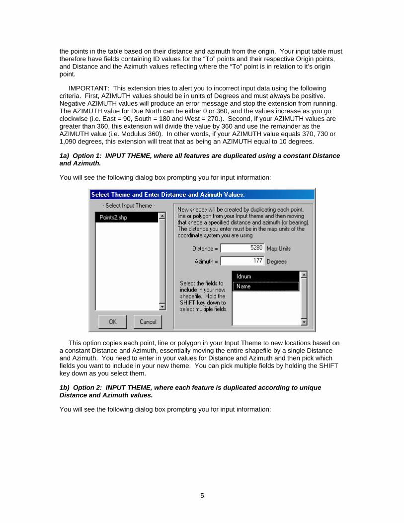
1a) Option 1: INPUT THEME, where all features are duplicated using a constant Distance and Azimuth.
You will see the following dialog box prompting you for input information:
This option copies each point, line or polygon in your Input Theme to new locations based on a constant Distance and Azimuth, essentially moving the entire shapefile by a single Distance and Azimuth. You need to enter in your values for Distance and Azimuth and then pick which fields you want to include in your new theme. You can pick multiple fields by holding the SHIFT key down as you select them.
1b) Option 2: INPUT THEME, where each feature is duplicated according to unique Distance and Azimuth values.
You will see the following dialog box prompting you for input information:
5

This option copies each point, line or polygon in your Input Theme to new locations based on unique Distance and Azimuth values that are found in DISTANCE and AZIMUTH fields in the theme's Feature Attribute Table. In this case, each point, line or polygon has it's own Distance and Azimuth value in the Distance and Azimuth fields, and the extension copies that shape to new coordinates based on those Distance and Azimuth values. In the illustration on the first page of this document, the author used a theme of the Continental United States and duplicated each state according to a couple of numeric fields, producing a map of scrambled states.
6

1c) Option 3: Single Shape Input Table: You will see the following dialog box prompting you for input information:
Begin by selecting the input table from the list of available tables. After you've selected your table, the fields for that table will appear in the four listboxes on the right. Select the fields that contain your "FROM", "TO", "DISTANCE" and "AZIMUTH" values.
Each record in the table should essentially reflect a line segment starting at one point and reaching to a new point created by the specified distance and azimuth. The next record in the table reflects a new line segment starting where the last one ended, and continues to a new point based on it's specified distance and azimuth.
This extension sorts the table according to the values in the "FROM" field, and these values can be understood as ID values for each vertex in the shape, or as ID values for each point in the final set of points. All calculations are done in the order of the sorted "FROM" values, so it is important to make sure these values are correct. After you've selected your "FROM" field, this extension will go through all the values in that field and find the lowest value. The extension assumes this lowest value is your Origin point and prompts you to enter the X- and Y-coordinates in the text boxes below the list boxes.
This extension assumes that there are no duplicate values in the "FROM" field. If duplicate values exist, the extension will not know how to sort them. The extension checks for duplicate values before it allows you to exit from this dialog box, and will prompt you with the following alert if it finds a duplicate "FROM" value. If you get this message, the author strongly recommends you repair your data before proceeding with your calculations.
7
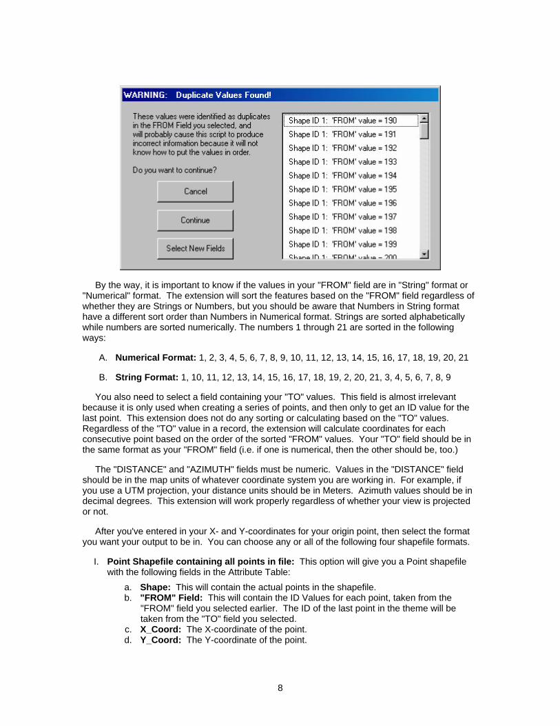
By the way, it is important to know if the values in your "FROM" field are in "String" format or "Numerical" format. The extension will sort the features based on the "FROM" field regardless of whether they are Strings or Numbers, but you should be aware that Numbers in String format have a different sort order than Numbers in Numerical format. Strings are sorted alphabetically while numbers are sorted numerically. The numbers 1 through 21 are sorted in the following ways:
A. Numerical Format: 1, 2, 3, 4, 5, 6, 7, 8, 9, 10, 11, 12, 13, 14, 15, 16, 17, 18, 19, 20, 21
B. String Format: 1, 10, 11, 12, 13, 14, 15, 16, 17, 18, 19, 2, 20, 21, 3, 4, 5, 6, 7, 8, 9
You also need to select a field containing your "TO" values. This field is almost irrelevant because it is only used when creating a series of points, and then only to get an ID value for the last point. This extension does not do any sorting or calculating based on the "TO" values. Regardless of the "TO" value in a record, the extension will calculate coordinates for each consecutive point based on the order of the sorted "FROM" values. Your "TO" field should be in the same format as your "FROM" field (i.e. if one is numerical, then the other should be, too.)
The "DISTANCE" and "AZIMUTH" fields must be numeric. Values in the "DISTANCE" field should be in the map units of whatever coordinate system you are working in. For example, if you use a UTM projection, your distance units should be in Meters. Azimuth values should be in decimal degrees. This extension will work properly regardless of whether your view is projected or not.
After you've entered in your X- and Y-coordinates for your origin point, then select the format you want your output to be in. You can choose any or all of the following four shapefile formats.
I. Point Shapefile containing all points in file: This option will give you a Point shapefile with the following fields in the Attribute Table:
a. Shape: This will contain the actual points in the shapefile. b. "FROM" Field: This will contain the ID Values for each point, taken from the
"FROM" field you selected earlier. The ID of the last point in the theme will be taken from the "TO" field you selected.
c. X_Coord: The X-coordinate of the point. d. Y_Coord: The Y-coordinate of the point.
8

II. A Set of Lines Reflecting Each Line Segment: This option gives you a line shapefile in which each line represents the line segment described by each record in your input table. It's made up of a series of line segments that connect to each other. The shapefile includes the following fields in the Attribute Table:
a. Shape: This will contain the actual line segments, marked as "Polylines". b. Length: This length is drawn from the "Distance" field you selected. c. Segment_ID: Each line segment is assigned an ID number as it's created. This
field contains those numbers. d. From: This contains the ID value of the beginning of the line segment, and it's
drawn from the "FROM" field you selected. e. To: This contains the ID value of the end of the line segment, and it's drawn from
the "TO" field you selected. f. Azimuth: This value is drawn from the "Azimuth" field you selected.
III. A Single polyline of combined line segments: This option gives you a single polyline of all the line segments linked together. The shapefile contains a single feature with the following fields:
a. Length: This represents the total length of the polyline. b. ID: This just gives the polyline an ID value which is useful in many circumstances.
It's ID value will be "1". IV. A Single polygon, connecting first and last points: This option gives you a polygon
created by connecting the last point in the series back to the origin point. The shapefile contains a single feature with the following fields:
a. Area: This represents the total area enclosed by the polygon. b. ID: This just gives the polygon an ID value which is useful in many circumstances.
It's ID value will be "1".
9

1d) Option 4: Multiple Shape Input Table:
You will see the following dialog box prompting you for input information:
This option is very similar to the "Single Shape Input Table" option described above, except that in this case your input table can contain multiple shapes. The input table must have a field containing ID values for each shape.
The output shapefiles are similar to those in the Single Shape Input Table above, except that each shapefile also includes a SHAPE ID field describing which shape that point, line segment, polyline or polygon is a part of. Also, the Polyline and Polygon shapefiles will contain multiple polylines or polygons.
The tool needs to know the origin points for each of your new shapes, and you can specify these origin points by either entering them manually or by linking to a table containing origin coordinates. After you have selected your “SHAPE ID” field, then the “Link To Table” button becomes active. After you have selected the fields containing your "SHAPE ID" and "FROM" fields, then the "Enter Coordinates" button becomes active.
Entering Origin Coordinates Manually: You will need to enter X- and Y-coordinates for the origin points of each of your shapes before you will be able to click the "OK" button. Once you click the "Enter Coordinates" button, you will see the following dialog prompting you for Origin coordinates for each shape:
10

The dialog checks to see how many unique shape ID values you have, then finds the lowest "FROM" value for each shape ID value. You can see these values on the dialog so you can be sure you're entering coordinates for the correct point. If you skip any of the SHAPE ID values, then the extension will not create new points, lines or polygons for those SHAPE IDs.
Entering Origin Coordinates by Linking to a Table: If you have a table containing the origin points of each of your shapes, you can skip entering the coordinates manually. Click on the “Link to Table” button to see the following dialog:
First identify the table containing your origin coordinates, then select the fields containing the Shape ID, X-Coordinate and Y-Coordinate values. IMPORTANT: The “SHAPE ID” field in this table must contain identical ID values to those specified in the “SHAPE ID” field from the Multiple Shape Input Table dialog (see above). This table should have only a single record for each unique ID value, containing a single set of X/Y-Coordinates for each shape. Once you have identified the relevant fields, click “OK”.
1e) Option 5: Input Table for Set of Points surrounding Origin Point:
You will see the following dialog box prompting you for input information:
11

This option is intended for situations in which you know the coordinates of an origin point, and you know the distance and azimuth from the origin to a set of features nearby, and you want to map the coordinates of those features. For example, someone wanting to map the coordinates of trees in forest stand could walk to a point and set a GPS receiver to gather the coordinates of that point. While the GPS is working, that person could use a compass and rangefinder to record the distance and azimuths to all the trees around them. This extension will convert all those distance and azimuth values into X- and Y-coordinates for each tree.
Begin by selecting the proper table from the “INPUT Table” list. When you select a table, the fields from that table will appear in the other four listboxes. You need to select the fields which reflect the ID values for the Origin points, the ID values for the new points (or “TO” points), and the Distance and Azimuth values.
You also need to enter in X- and Y-coordinates for your Origin points. Once you’ve selected the “ORIGIN ID” field, the “Enter Coordinates” and “Link to Table” buttons will become active and allow you to assign coordinates for each origin point (see “1d) Option 4: Multiple Shape Input Table” for a description of how these buttons work).
You have three output options.
I. A POINT shapefile containing all points in file: This option gives you a Point shapefile where the points reflect the X- and Y-coordinates of all the “TO” values in your Input Table. The Feature Attribute Table for this shapefile will contain the X- and Y-coordinate values for the point, as well as all the other fields in your original Input table.
II. A Set of Lines connecting the points to the Origin: This option gives you a Polyline shapefile where each line represents the straight-line distance between the Origin point and the “TO” point. The Feature Attribute Table for this shapefile will contain all the fields in your original Input table.
12

III. A POINT shapefile or Origin points: This option gives you a Point shapefile containing a separate point for each unique Origin point. If your Input table contains 200 records, but they only refer to 4 origin points, then this shapefile will only contain those 4 points. The Feature Attribute table for this shapefile will contain the Origin point ID values and the X- and Y-coordinates of the points.
2) Specify Hard Drive Locations to save new Shapefiles: After you've clicked the "OK" button, you will be prompted to specify a location on the hard drive to save your new shapefiles. These are standard ArcView Dialog Boxes and should be familiar to most users. These files are permanent and will not be deleted when ArcView is shut down.
13

Instructions for Calculating Average Bearings of Polylines: This is a simple function to calculate the average bearing of polylines, defined as the direct bearing from the start- to the end-point of a polyline. If you wish to calculate more sophisticated statistics on polylines, including decomposing them into a series of segments and vertices, the author recommends his “Path, with Distances and Bearings” extension (see http://www.jennessent.com/arcview/path.htm).
Click the button to start the process. This button will not be enabled unless there is at least 1 polyline theme present in the view.
You will first be prompted to identify the polyline theme to use:
Next identify the field to save the azimuth values in:
If you choose “<- Make New Field ->”, then you will need to define your field parameters:
14

Click “OK” and the tool will to work. It will notify you when it has finished:
You will need to open the table to see the new values.
Instructions for the three ToolBar tools:
Line Length and Azimuth: This tool allows you draw a line anywhere on your display by clicking at some point and holding the mouse button down as you move the cursor to a new point. When you let up on the mouse button, the Bearing (or Azimuth), Length, and Start/End Coordinates of that line will appear at the bottom of the screen. This message is also saved to your clipboard.
This function also draws a gray line on your screen where you dragged your cursor. Previous gray lines will disappear as you draw new lines. Hold the [Shift] key down as you draw if you want the previous lines to stay on the screen. The Graphic Point from Distance and Azimuth and the Graphic Point from Point Theme tools are similar in that both allow you to calculate the coordinates of a new point based on the distance and azimuth from an existing point. They each produce a graphic symbol at the new point coordinates, and draw a graphic line connecting the origin point to the new point.
Graphic Point from Distance and Azimuth: This tool allows you to click anywhere on the screen and a graphic symbol will appear at that point. You will then be prompted to enter a Distance and Azimuth (see illustration below), and the tool will then calculate a new point according to the values you enter. The coordinates for the new point will appear at the bottom of the screen, and a graphic symbol will appear at the coordinates of that new point. This message is also saved to your clipboard.
Graphic Point from Point Theme: This tool calculates a new point based on a distance and azimuth from an existing point, and requires that you have a Point theme active in your view. When you click on a point from that Point theme, you will be prompted to enter a Distance and Azimuth (see illustration below), and the tool will then calculate a new point according to the values you enter. The coordinates for the new point will appear at the bottom of the screen, and a graphic symbol will appear at the coordinates of that new point. The message is also saved to your clipboard.
15

Updates:
Version 1.2 corrects a bug that occurs when the input bearing is exactly 90 degrees. Previously the extension would treat that instance as if the bearing was 45 degrees.
Version 1.3 fixes a "Variable TheEdgeBearing has not been initialized" error that occurs when using the Line Length and Azimuth tool. This version also saves the line length and azimuth to the clipboard, and reports the azimuth in both azimuthal degrees and compass quadrant bearings.
Version 1.4 adds the option to link to a table containing origin coordinates rather than entering them individually. This release also corrects a bug in which a feature with no bearing/azimuth value would receive the value from the previous feature, and such cases are now summarized in a report at the end of calculation rather than with an alert message each time.
Version 1.4e (Sept. 17, 2003) adds the capability to use themes with Z- and M-attributes and use String fields for distance / azimuth / origin values.
Version 1.5 (Sept. 29, 2004) adds the capability to calculate average bearings of polylines.
Version 1.6 (Feb. 21, 2005) fixes some bugs related to projections and makes some general changes.
a) It was not positioning shapes correctly when the view was projected and the user built the shapes from an input table.
b) the “Graphic Shape from Distance and Azimuth” tool would calculate values based on the geographic projection even if the view was projected.
c) This version also modifies the “Line Length and Azimuth” so it erases previous graphics as you draw them. It will not delete previous graphics if you hold down the shift key as you draw lines.
d) I cleaned up the initial Analysis Type dialog so that it does not have nearly as much text on it. I also added Help buttons to explain the different options.
16
An On-line version of this manual may be viewed at:
http://www.jennessent.com/arcview/distance_azimuth.htm
Enjoy! Please contact the author if you have problems or find bugs. Jeff Jenness [email protected] 3020 N. Schevene Blvd. Flagstaff, AZ 86004 USA
Please visit Jenness Enterprises ArcView Extensions site for more ArcView Extensions and other software by the author. We also offer customized ArcView-based GIS consultation services to help you meet your specific data analysis and application development needs.
17