nanostructures for water purification - department of civil engineering …€¦ · ·...
TRANSCRIPT

Nanostructures for Water Purification
Zheng-Xiao GUO
LCN / TYC – London / Department of Chemistry University College London
[email protected]; www.chem.ucl.ac.uk

London’s Global University
Francis Crick Mahatma Gandhi
- Over 4300 academic staff in 8 faculties- Over 24,000 students (~1/3 overseas)- Over 150 Fellows of the Royal Society, the British Academy, the Royal Academy of Engineering, and the Academy of Medical Sciences
- 21 Nobel Prize winners …
UCL breakthroughs- First transatlantic connection- the internet- Identification of hormones and vitamins- Discovery of inert gases, including neon (1st UK Nobel Prize in Chemistry)
…
Charles Kuen Kao ( 高锟 )

“If all the earth's freshwater were stored in a 5-liter container, available fresh water would not quite fill a teaspoon…, ~ 0.08 – 1 % ”
(Source: World Water Council)

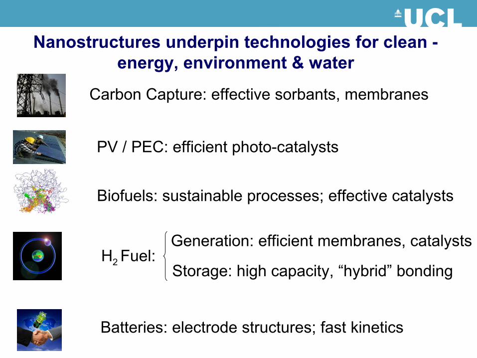
Nanostructures underpin technologies for clean -energy, environment & water
Carbon Capture: effective sorbants, membranes
PV / PEC: efficient photo-catalysts
H2 Fuel:Generation: efficient membranes, catalysts
Storage: high capacity, “hybrid” bonding
Biofuels: sustainable processes; effective catalysts
Batteries: electrode structures; fast kinetics
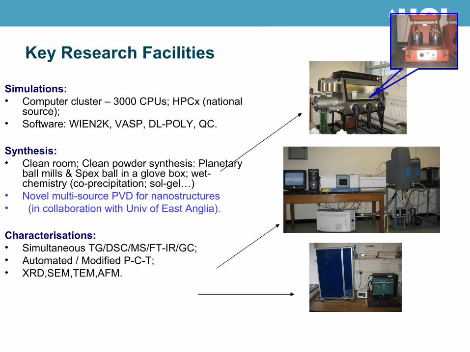
Key Research Facilities
Simulations:• Computer cluster – 3000 CPUs; HPCx (national
source);• Software: WIEN2K, VASP, DL-POLY, QC.
Synthesis:• Clean room; Clean powder synthesis: Planetary
ball mills & Spex ball in a glove box; wet-chemistry (co-precipitation; sol-gel…)
• Novel multi-source PVD for nanostructures• (in collaboration with Univ of East Anglia).
Characterisations:• Simultaneous TG/DSC/MS/FT-IR/GC;• Automated / Modified P-C-T;• XRD,SEM,TEM,AFM.
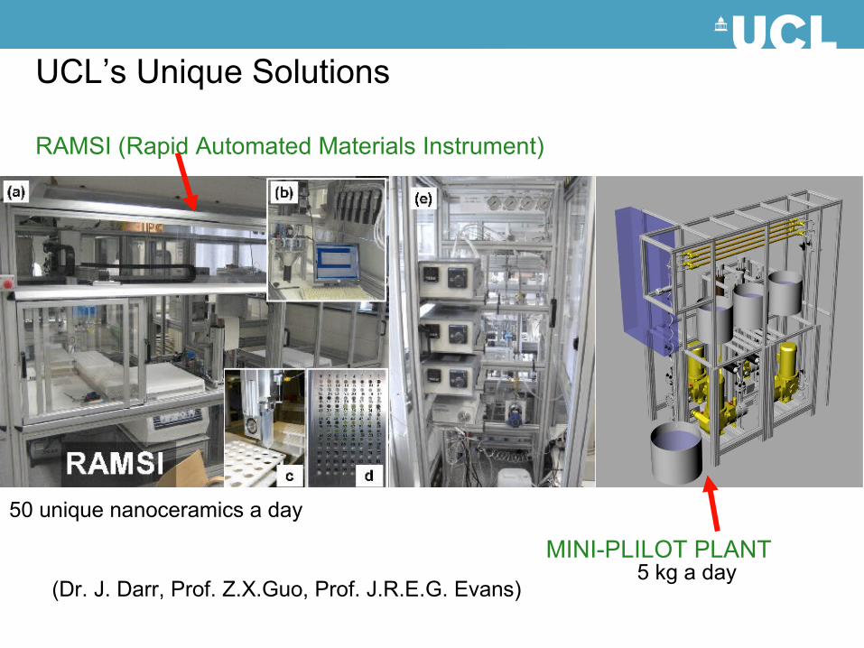
UCL’s Unique Solutions
RAMSI (Rapid Automated Materials Instrument)
MINI-PLILOT PLANT
50 unique nanoceramics a day
5 kg a day(Dr. J. Darr, Prof. Z.X.Guo, Prof. J.R.E.G. Evans)
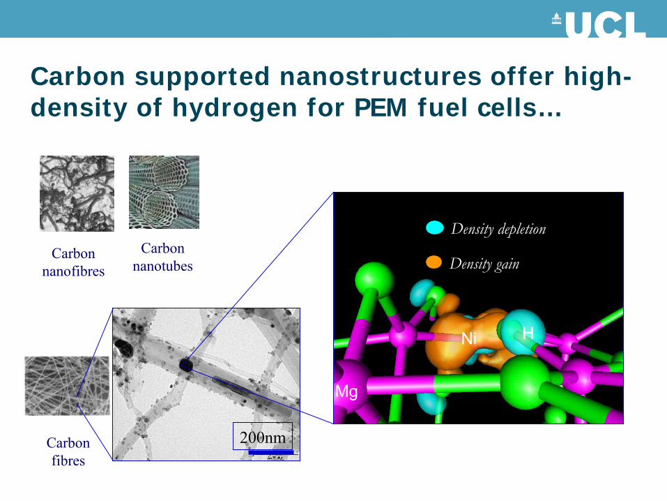
Carbon supported nanostructures offer high-density of hydrogen for PEM fuel cells…
Carbon nanotubes
Carbon nanofibres
Carbon fibres
200nm
Density depletion
Density gain
Mg
HNi
1 µm
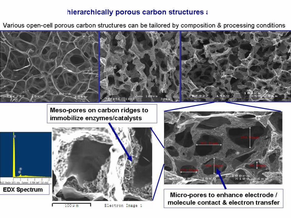
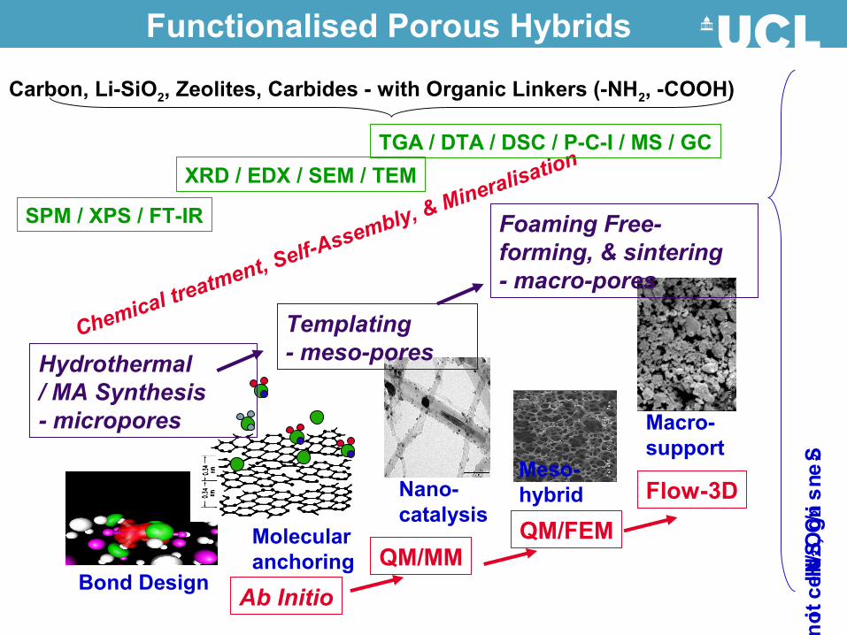
Functionalised Porous Hybrids
Bond Design
Atomic / Molecular anchoring
Nano- catalysis
Meso- hybrid
Macro- support
H2 / N
2 / CO
2 Sensing, Selection, Separation, Storage
Carbon, Li-SiO2, Zeolites, Carbides - with Organic Linkers (-NH2, -COOH)
Chemical treatment, Self-Assembly, & Mineralisation
Ab InitioQM/MM
QM/FEMFlow-3D
Hydrothermal/ MA Synthesis- micropores
Templating - meso-pores
Foaming Free-forming, & sintering - macro-pores
SPM / XPS / FT-IR
XRD / EDX / SEM / TEMTGA / DTA / DSC / P-C-I / MS / GC

Catalytic CO2 Activation & Sorption
Li and Guo, JPCC, 2010, 114, 11456

Molecular self-assembly
O
O OH OH OSiHO OH
Substrate
NH2
SiO
O OOSi Si
OO Si
OO
Substrate
NH2
+ H2O+ 3C2H5OH
(a)Si H3CH2CO OCH2CH3
OCH2CH3
NH2
Si OH OH
OH
NH2
(APTES) (APS)- H2O(b)
SiHO OH
NH2
- H2O
(c)
(Formation of covalent bonds)
NH2 NH2NH2
(Ordering of APS film)
How to form a well-ordered film on How to form a well-ordered film on substrate?substrate?
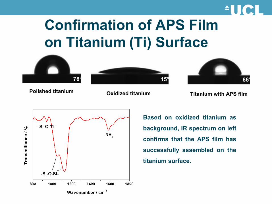
Confirmation of APS Film on Titanium (Ti) Surface
Polished titanium
78°
Oxidized titanium
15°
Titanium with APS film
66°
Based on oxidized titanium as
background, IR spectrum on left
confirms that the APS film has
successfully assembled on the
titanium surface.

Biofuel Cell Electrode Structures & H2 Pathways
Immobilisation of catalytic Enzymes onto porous electrode structures to enhance electron transfer and electrocatalysis.
b)
Trajectories of H2 to the active site with different colours indicating different H2 molecules

Photocatalytic purification of water
Junwang Tang(Chem Eng)
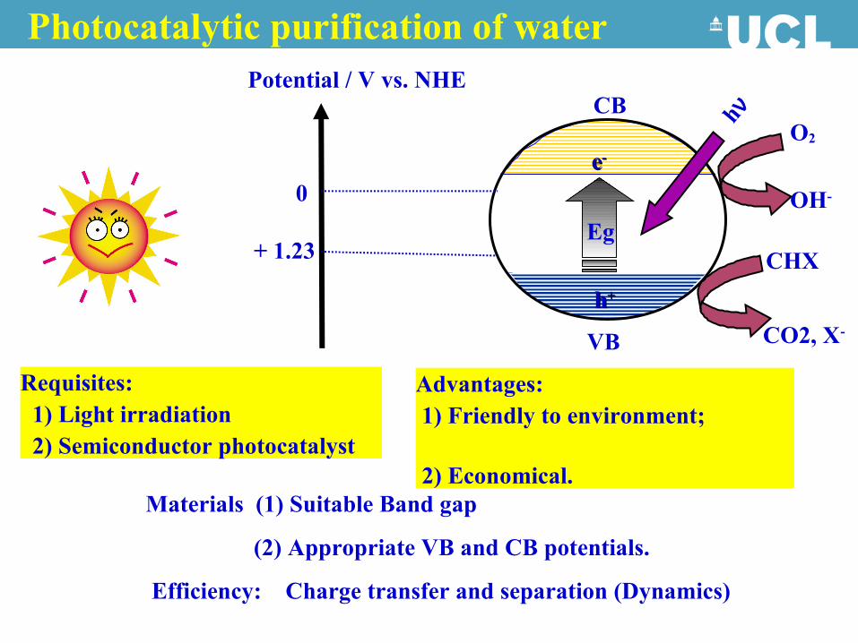
Photocatalytic purification of water
+ 1.23
0
Potential / V vs. NHE
ee--
hh++
VB
CB
Eg
hν
Materials (1) Suitable Band gap
(2) Appropriate VB and CB potentials.
Efficiency: Charge transfer and separation (Dynamics)
Requisites: 1) Light irradiation 2) Semiconductor photocatalyst
Advantages: 1) Friendly to environment; 2) Economical.
OH-
O2
CO2, X-
CHX
1. R. Asahi, T. Morikawa, T. Ohwaki, K. Aoki, Y. Taga, Science 293 (2001) 269.
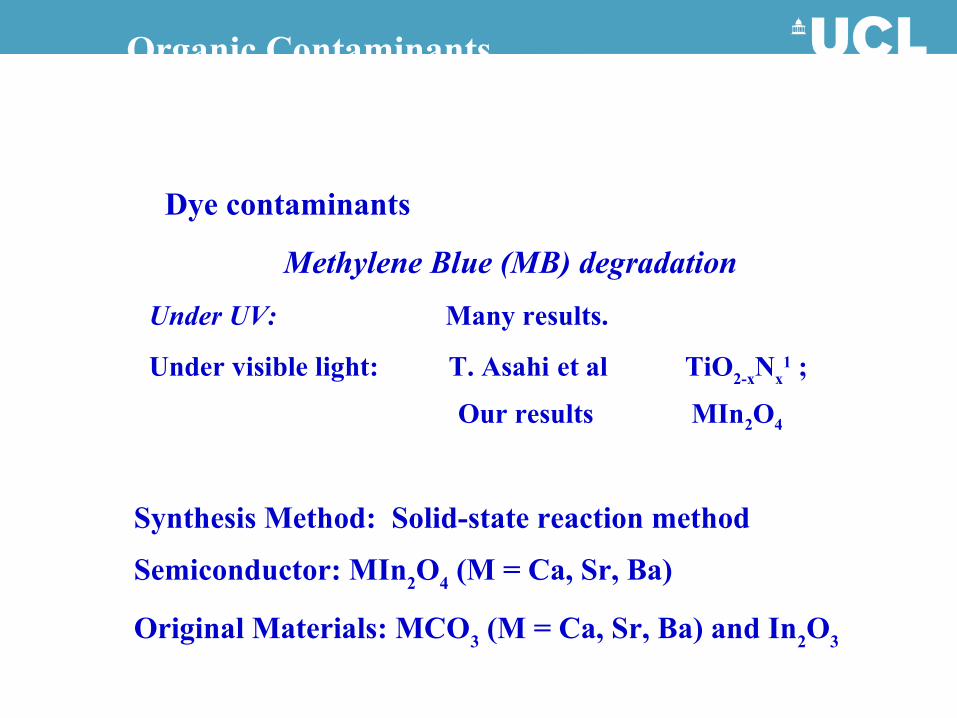
Organic Contaminants
Dye contaminants
Methylene Blue (MB) degradationUnder UV: Many results.
Under visible light: T. Asahi et al TiO2-xNx1 ;
Our results MIn2O4
Synthesis Method: Solid-state reaction method
Semiconductor: MIn2O4 (M = Ca, Sr, Ba)
Original Materials: MCO3 (M = Ca, Sr, Ba) and In2O3
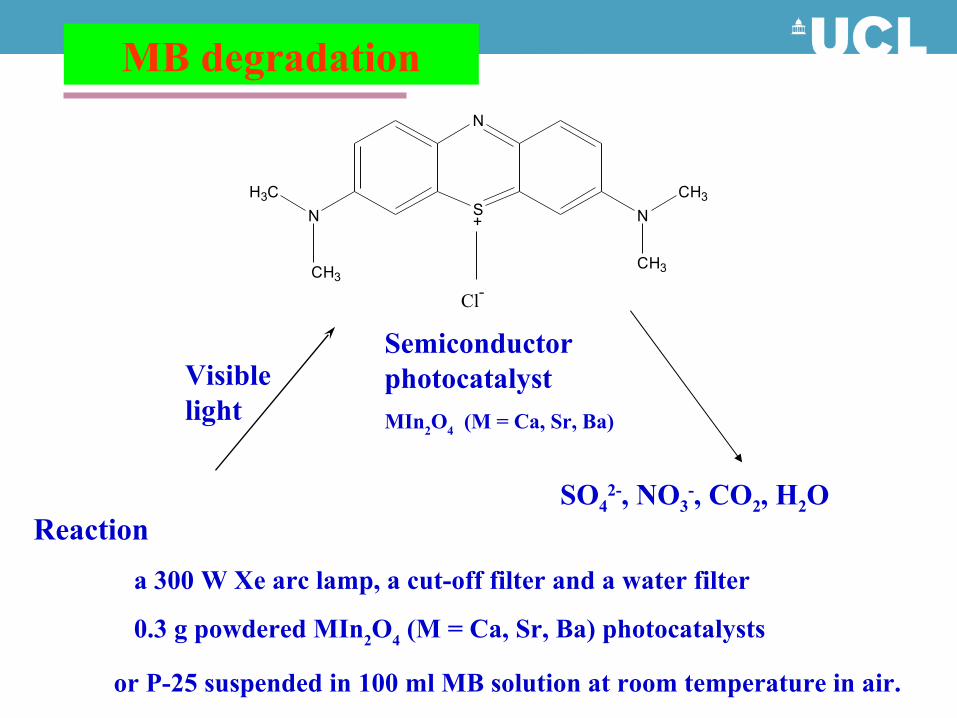
MB degradation
S+
N
N
CH3
CH3
NH3C
CH3
Cl-
Visible light
Semiconductor photocatalystMIn2O4 (M = Ca, Sr, Ba)
SO42-, NO3
-, CO2, H2OReaction a 300 W Xe arc lamp, a cut-off filter and a water filter
0.3 g powdered MIn2O4 (M = Ca, Sr, Ba) photocatalysts
or P-25 suspended in 100 ml MB solution at room temperature in air.
0
5
10
15
20
0 30 60 90 120
Time (min)
MB
Concentr
atio
n (
mg/
l)
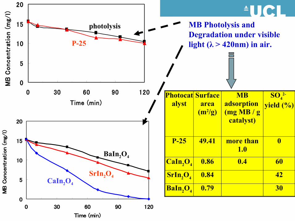
MB Photolysis and Degradation under visible light (λ > 420nm) in air.
0
5
10
15
20
0 30 60 90 120
Time (min)
MB
Concentr
ati
on (
mg/
l)
CaIn2O4
SrIn2O4
BaIn2O4
P-25
photolysis
Photocatalyst
Surface area
(m2/g)
MB adsorption (mg MB / g
catalyst)
SO42-
yield (%)
P-25 49.41 more than 1.0
0
CaIn2O4 0.86 0.4 60
SrIn2O4 0.84 42
BaIn2O4 0.79 30
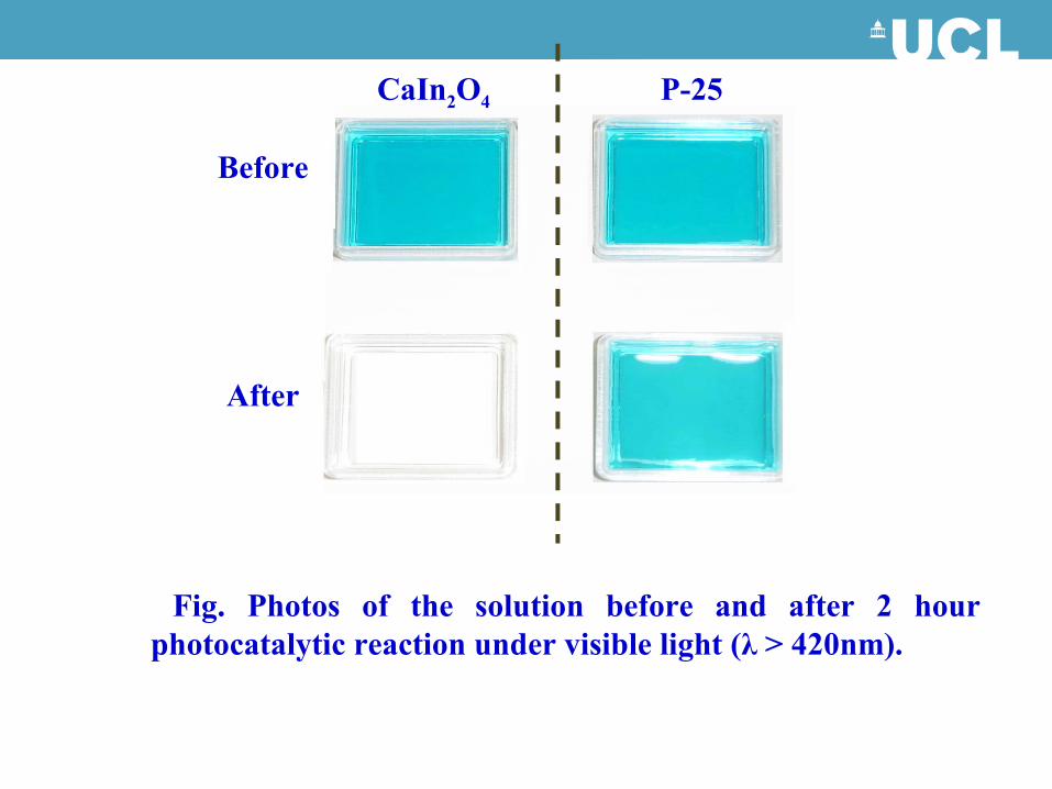
Fig. Photos of the solution before and after 2 hour photocatalytic reaction under visible light (λ > 420nm).
Before
After
CaIn2O4 P-25
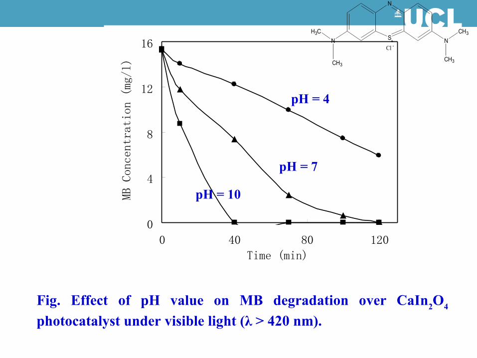
0
4
8
12
16
0 40 80 120
Time (min)
MB Concentration (mg/l)
Fig. Effect of pH value on MB degradation over CaIn2O4 photocatalyst under visible light (λ > 420 nm).
pH = 7
pH = 10
S +
N
N
CH3
CH3
NH3C
CH3
Cl -
pH = 4


Centre for Water Advanced Technologies and Environmental Research (C WATER)
Swansea UniversityUnited Kingdom
Professor Nidal HilalDr Chedly Tizaoui
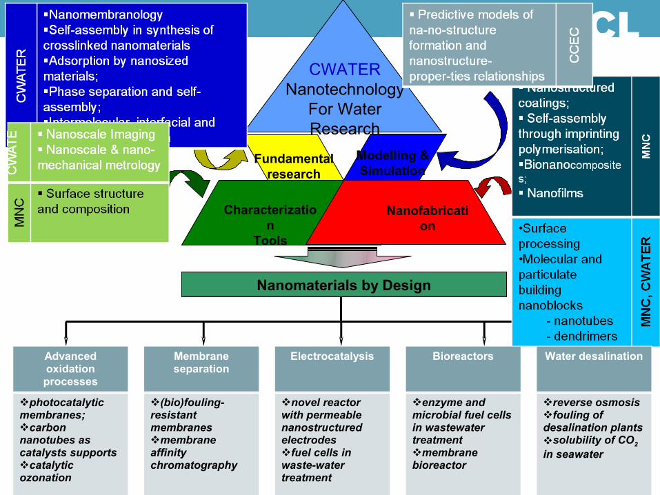
Characterization
Tools
Modelling & Simulation
Fundamental research
CWATERNanotechnology
For Water Research
Nanofabrication
Nanomaterials by Design
Advanced oxidation processes
Membrane separation
Electrocatalysis Bioreactors Water desalination
photocatalytic membranes;carbon nanotubes as catalysts supportscatalytic ozonation
(bio)fouling-resistant membranesmembrane affinity chromatography
novel reactor with permeable nanostructured electrodesfuel cells in wastewater treatment
enzyme and microbial fuel cells in wastewater treatmentmembrane bioreactor
reverse osmosisfouling of desalination plantssolubility of CO2 in seawater
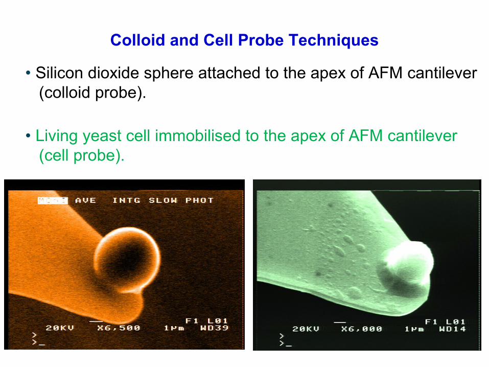
Colloid and Cell Probe Techniques
• Living yeast cell immobilised to the apex of AFM cantilever (cell probe).
• Silicon dioxide sphere attached to the apex of AFM cantilever (colloid probe).

Atomic Force Microscopy imageBio-colloid of 0.3 µm Blocking
MF Membrane Pore
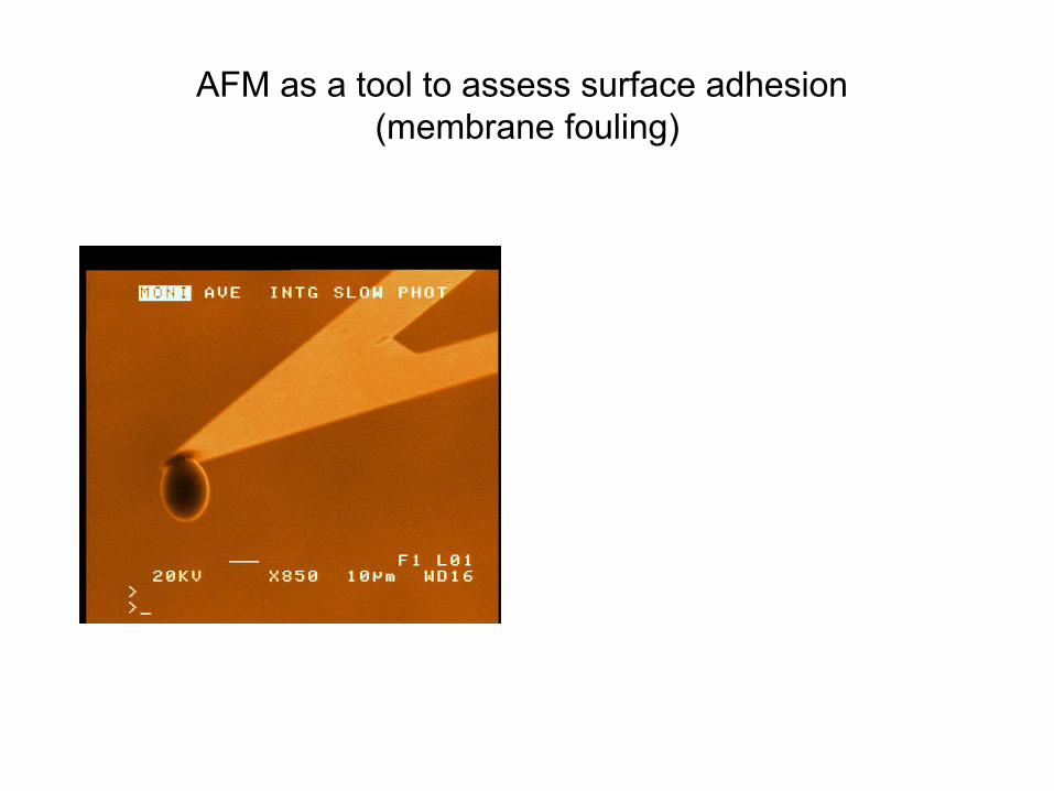
AFM as a tool to assess surface adhesion (membrane fouling)
Piezo displacement (nm)1000 1200 1400 1600 1800 2000
F/R
(mN
/m)
-3
-2
-1
0
1
2
3
4
5ES 404 membraneXP 117 membrane
A
A'
B
CD
(b)

Development of (bio)fouling resistant membranes
Photograph of initial PVDF(left),& PVDF modified membranes
Photograph of initial PES (right),& PES modified membranes
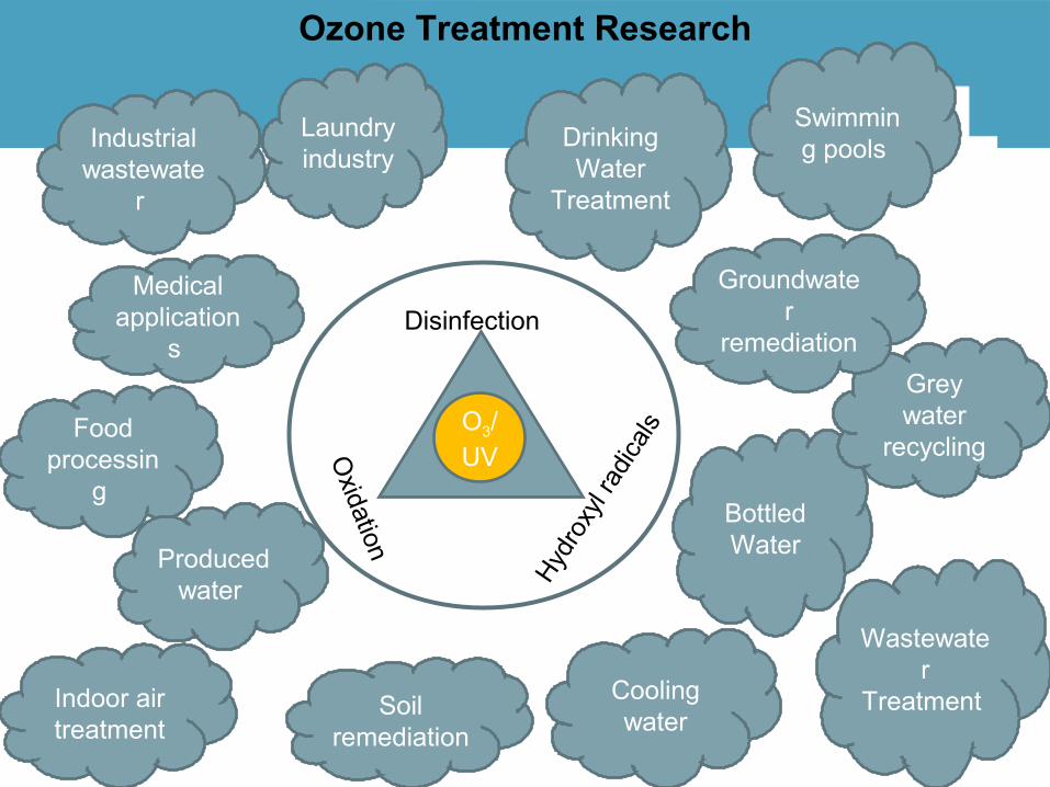
Ozone Treatment Research
Drinking Water
Treatment
Wastewater
Treatment
O3/UV
Disinfection
Oxidation
Hydr
oxyl
radic
als
Medical application
s
Indoor air treatment
Bottled Water
Soil remediation
Laundry industry
Cooling water
Food processin
g
Industrial wastewate
r
Grey water
recycling
Swimming pools
Groundwater
remediation
Produced water
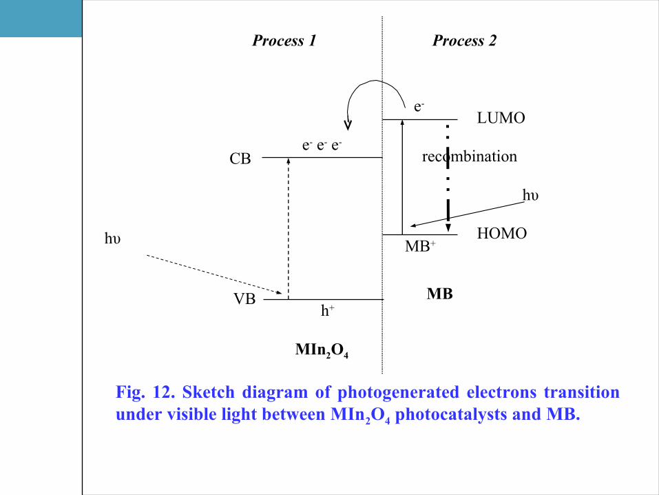
Fig. 12. Sketch diagram of photogenerated electrons transition under visible light between MIn2O4 photocatalysts and MB.
Process 2Process 1
LUMO
HOMO
MBVB
CB
MIn2O4
hυ
hυ
h+
e- e- e-
e-
MB+
recombination