nasa contractor report · 2.0 introduction the statement of work for nasa contract nas1-17635, task...
TRANSCRIPT
a
NASA Contractor Report 1 7 8 1 5 5
(NASA-CE-178155) A U T C M B T I C E E A K I N G SYSTEI3 M87-13446 H D D I F I C A T I O N E C f i THE A C V A N C E I : Z E A N S P O R T O P E E A T I N G SYS!IE M3 (ATCPS) ‘IPAhSECBTATXCN SYSTEMS R E S E A f i C H V L H I C L E (TSIiV) Final Unclas Iieport (Boeinq Commercial A ir f lans Co. ) G3/08 Q3565
AUTOMATIC BRAKING SYSTEM MODIFICATION FOR THE ADVANCED TRANSPORT OPERATING
SYSTEMS (ATOPS) TRANSPORTATION
SYSTEMS RESEARCH VEHICLE (TSRV)
James J . Coogan
BOEING COMMERCIAL AIRPLANE COMPANY S e a t t l e , Washington
C o n t r a c t NAS1-17635 O c t o b e r 1986
National Aeronautics and Space Administration
Langley Research Center Harr?$on,?/i:gin;a 23665
https://ntrs.nasa.gov/search.jsp?R=19870004013 2018-05-27T07:21:49+00:00Z
TABLE OF CONTENTS
1.0
2.0
3.0
TABLE OF CONTENTS
LIST OF FIGURES
SUMMARY
INTRODUCTION
AUTOBRAKE MODIFICATION DESIGN
3 . 1 Background on Current System
3 . 2 Autobrake Arming Logic Modifications
.
3 . 3 Deceleration Control Circuit Modifications
3 . 4 Aft Flight Deck Interface
4.0 SIMULATED SYSTEM PERFORMANCE
4.1 Test Set Up
4.2 Test Conditions
4 . 3 Test Results
5.0 CONCLUSIONS
REFERENCES
1
ii
1
2
3
3
5
6
7
15
15
18
20
67
69
i
NUMBER
1
2
3
4
5
6
7
8
9
10
11
12
13
14
15
16
17
18
19
20
21
22
23
24
25
LIST OF FIGURES
TITLE
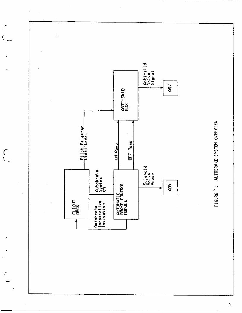
Autobrake System Overview
__.
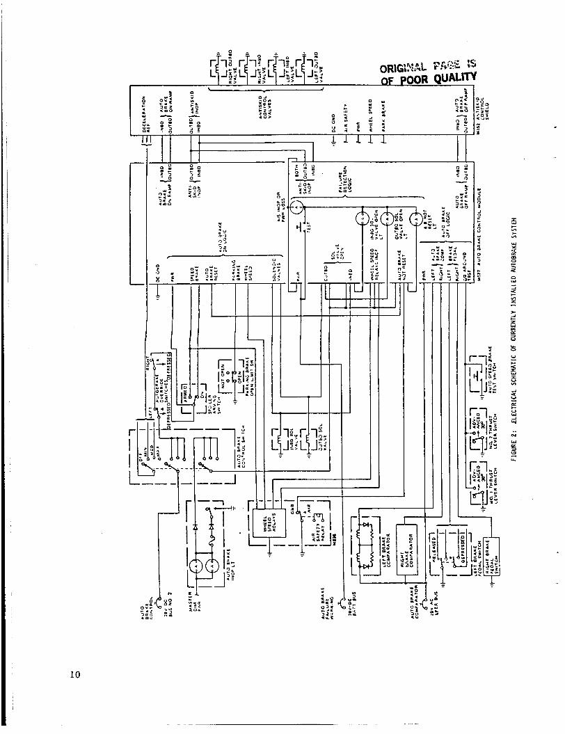
Electrical Schematic of Currently Instal led Autobrake System
Current Autobrake Power Circuit
Autobrake Control Loop
Modified Automatic Braking System Control Circuit
Modified Deceleration Command Circuit
Hybrid Brake Control Laboratory
CV Autobrake Test Setup
Test Matrix
Time History Data, Run 001
Time History Data, Run 002
Time History Data, Run 003
Time History Data, Run 004
Time History Data, Run 010
Time History Data, Run 015
Time History Data, Run 101
Time History Data, Run 103
Time History Data, Run 104
Time History Data, Run 106
Time History Data, Run 201
Time History Data, Run 202
Time History Data, Run 204
Time History Data, Run 304
Time History Data, Run 404
Time History Data, Run 409
PAGE
9
10
11
12
13
14
24
25
26
27
29
31
33
35
37
39
41
43
45
47
49
51
53
55
57
-
ii
26 Time History Data, Run 504
27 Time History Data, Run 509
28 Time History Data, Run 601
29 Time History Data, Run 701
59
61
63
65
. iii

1 .O SUMMARY
Modifications to the 737-100 autobrake system were designed, under NASA
Contract NAS1-17635, Task 7. These modifications will enable an on-board
flight control computer to control aircraft deceleration to a continuously
variable level, for the purpose of executing automatic high speed turn-offs.
The design problem and proposed solution are described in this report.
A breadboard version of the proposed modifications was built and tested in
simulated stopping conditions. Test results, presented here, show the
effectiveness and limitations of the system.
Implementation on the TSRV 737 and flight testing of the proposed design
modifications is planned for Phase I1 of the program.
2.0 INTRODUCTION
The Statement of Work fo r NASA Contract NAS1-17635, Task 7 , c a l l s for
modification of t h e 737-100 autobrake s y s t e m t o allow continuously variable
deceleration control, i n response t o a deceleration command generated i n an
avionics computer.
system t o automatically b r i n g the a i r c r a f t t o a par t icular speed, a t a
particular spot on the runway, t o allow automatic, high speed t u r n offs .
is required that the modifications do not a f fec t the operation of the
current 3-level autobrake system o r of t h e anti-skid system.
a b i l i t y t o override the automatic system, and related safety features m u s t
be unaffected.
The purpose of t h i s development is t o use t h e braking
It
The p i l o t ' s
Phase I is an engineering s t u d y and modification design.
Control laws fo r automatic deceleration and t u r n o f fs were developed under
an e a r l i e r N A S A Contract (Reference 1 ) . The scheme developed was to use
reverse thrust as the main stopping force, and use the braking s y s t e m for
f ine closed loop deceleration control. Algorithms t o compute the desired
reverse thrust level , and the deceleration command signal were presented i n
.Reference 1, and a re used here. The deceleration command, a t any moment, is
j u s t the average deceleration required t o bring the a i r c ra f t from the
current speed to the desired t u r n speed, i n the amount of space available
before the t u r n .
s ignals.
The signal is ra te limited t o provide smoothly varying
The desired reverse t h r u s t is computed a t the s t a r t of the landing
ro l lou t , on the premise that t h e brakes w i l l not be used t o slow the
a i r c ra f t . Aerodynamic drag and t i r e ro l l ing resistance a re accounted for i n
the comjmtation (presented i n Reference 1 ) . The Statement of Work, and the
earlier contract work provide the context for this design effort. I
2
i i
i -
3.0 AUTOBRAKE MODIFICATION D E S I G N
The d e s i g n o b j e c t i v e is t o e n a b l e t h e a u t o b r a k e sys t em t o c o n t r o l
d e c e l e r a t i o n t o a c o n t i n u o u s l y v a r i a b l e l e v e l .
is t o be a c t i v a t e d when t h e p i l o t selects "VARIABLE", w i t h h i s a u t o b r a k e
control swi t ch , and t h e F l i g h t Con t ro l Computer i n d i c a t e s i t is r e a d y t o
direct t h e brake sys tem. The F l i g h t C o n t r o l Computer w i l l p r o v i d e two
s i g n a l s . The first s i g n a l , CV DECEL ON discrete, i n d i c a t e s t h a t t h e
computer is r e a d y t o direct t h e system. The second is a n a n a l o g s i g n a l ,
which i n d i c a t e s t he desired d e c e l e r a t i o n l e v e l .
The v a r i a b l e b r a k i n g sys t em
I t is r e q u i r e d t h a t t h e m o d i f i c a t i o n s do n o t affect t h e o p e r a t i o n of t h e
c u r r e n t 3 - l eve l a u t o b r a k e sys tem or of the a n t i - s k i d system. The p i l o t ' s
a b i l i t y t o o v e r r i d e t h e a u t o m a t i c sys t em, and related s a f e t y f e a t u r e s must
be u n a f f e c t e d . If t h e p i l o t selects t h e v a r i a b l e a u t o m a t i c b r a k i n g sys t em,
and t h e F l i g h t C o n t r o l Computer is n o t r e a d y t o direct t h e sys t em, t h e
''AUTOBRAKE INOP" i n d i c a t o r lamp s h o u l d l i g h t .
The d e s i g n m o d i f i c a t i o n s can be grouped i n t o 3 categories.
p e r t a i n s t o t h e A f t F l i g h t Deck and its i n t e r f a c e wi th t h e Forward F l i g h t
Deck. A s econd deals w i t h t h e a u t o b r a k e a rming and s a f e t y logic.
p e r t a i n s t o t h e d e c e l e r a t i o n control loop .
One g roup
The l a s t
3.1 Background on C u r r e n t System
F i g u r e 1 is a n o v e r a l l s c h e m a t i c diagram showing o n l y t h e major components
and s i g n a l s of t h e a u t o b r a k e system c u r r e n t l y i n s t a l l e d i n t h e TSRV
a i r c r a r t . Figure 2 is a more d o t i i l o d view shnving external wiring of most

components.
Each stage is part of a separate c i r cu i t and has a separate function. One
stage, wired t o the autobrake c i r cu i t breaker, is used to power the
autobrake system when the p i lo t t u r n s i t on. Another stage connects t h e
autobrake inoperative l i g h t t o its control signal.
one is shown i n Figure 2 , inboard and outboard, a r e ident ica l ) a r e used t o
t e l l the deceleration control cards which se t t i ng the p i lo t has selected.
Note that the autobrake control switch is a multi-stage switch.
Two more stages (only
Figure 3 provides a closer look a t the autobrake power c i r cu i t . When the
p i lo t moves the autobrake switch t o one of the three llON1l posit ions, ( M I N ,
MED, or M A X ) , he powers the autobrake system. Power (28 VDC) from the
autobrake c i r cu i t breaker passes through the brake pedal switches t o the
automatic brake control module. Th i s box contains logic c i r cu i t s t o check
t h r o t t l e positions, brake pressure levels , air/ground sensing, wheel s p i n u p ,
e tc . I t a lso checks for cer ta in e l ec t r i ca l fa i lures . If everything is OK,
the automatic brake control module connects 28 VDC t o the autobrake valves,
and to the "ON RAMP Power" l i n e t o the anti-skid module. "ON RAMP Power"
act ivates the deceleration control feedback system. The autobrake valves
port f u l l hydraulic system pressure t o the anti-skid valves, which control
brake pressure.
Deceleration control is accomplished by the "Selected Decel" cards (see
Figure 4 ) i n the a n t i - s k i d control box. Wheel speed s ignals from the anti-
s k i d cards a re used for sensing, and the control is effected by modulating
brake pressure through anti-skid valves. The decel control card generates a
reference velocity from the measured wheel speeds and the desired
deceleration. The wheel speed error ( the difference between the velocity
r e f e r e n c e and t h e a v e r a g e of the two wheel s p e e d s ) is i n t e g r a t e d t o g e n e r a t e
t h e c o n t r o l s i g n a l , which is s e n t t o t h e a n t i - s k i d v a l v e s . Whenever
n e c e s s a r y , the a n t i - s k i d sys t em can o v e r r i d e that s i g n a l and r e d u c e brake
p r e s s u r e below t h e l e v e l cal led f o r by the d e c e l e r a t i o n c o n t r o l l oop .
The v o l t a g e mode on t h e autobrake card whch r e p r e s e n t s t h e desired
d e c e l e r a t i o n ( a n i n p u t t o t h e v e l o c i t y r e f e r e n c e c i r c u i t ) is c o n t r o l l e d
th rough t h e a u t o b r a k e c o n t r o l s w i t c h (as shown i n F i g u r e 4 ) . The p i l o t se t s
the s w i t c h to M I N , MED, or MAX, which changes t h e resistor network tha t
d e t e r m i n e s t h e d e c e l e r a t i o n command.
3.2 Autobrake Arming Logic M o d i f i c a t i o n s
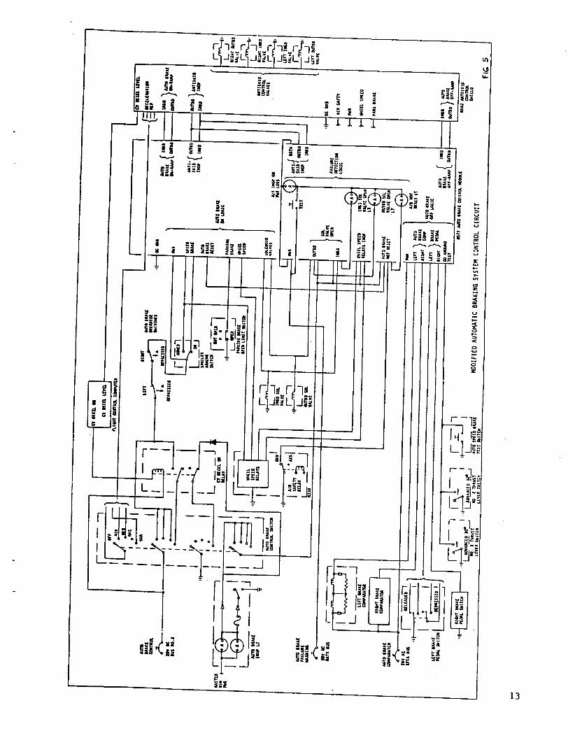
F i g u r e 5 is a schematic of t h e modified a u t o b r a k e sys tem. The effect of
s e l e c t i n g M I N , MED, or MAX is unchanged. S e l e c t i n g v a r i a b l e decel c o n n e c t s
power t o one c o n t a c t of t h e CV DECEL ON r e l a y . If t h e r e l a y is t u r n e d on by
t h e CV DECEL ON s i g n a l from t h e F l i g h t C o n t r o l Computer, t h e autobrake
sys tem is powered th rough t h e same c i r c u i t s t h a t c u r r e n t l y a c t i v a t e t h e
system. T h i s d e s i g n r e t a i n s a l l of t h e s a f e t y l o g i c b u i l t i n t o t h e
a u t o m a t i c brake c o n t r o l module.
To implement t h e r e q u i r e d au tob rake i n o p e r a t i v e i n d i c a t i o n , we have des igned
a n a d d i t i o n a l s t a g e i n t o t h e au tob rake swi t ch . T h i s s t a g e has t h e wiper
grounded and t h e c o n t a c t co r re spond ing t o t h e VAR s e t t i n g connec ted t h r o u g h
t h e CV DECEL ON r e l a y t o t h e inop l i g h t . If v a r i a b l e decel is selected and
the relay is nnt. t.urned el?, t h e lamp w i l l light.
5
These features can be implemented wi th minor modifications t o the forward
f l i g h t deck and to the a i r c r a f t w i r i n g .
components replaced and added t o the f l i g h t deck panel P2-2. A new
autobrake control switch is required.
be instal led behind the panel i n a mounting plate added for that purpose.
The autobrake control switch wiring is modified s l igh t ly . Also, the l i g h t
plate on the face of the panel is replaced wi th one showing the new
autobrake mode.
Drawing 64-35051 specif ies t h e
The additional relay and diode w i l l
The e l ec t r i ca l connectors on the panel must be rewired t o accommodate three
new signals. The CV DECEL ON s ignal that controls the relay is added, and
the two AUTOBRAKE V A R signals are picked up from the anti-skid box.
3 . 3 Deceleration Control Circuit Modifications
The continuously variable deceleration command is an analog signal picked up
from the experimental P l i g h t control computer. I t is scaled such that 0
v o l t s represents a deceleration of 0 feet/sec/sec, and -10 volts represents
10 feet/sec/sec. An op-amp network was designed t o take t h i s signal and
produce a deceleration signal compatible wi th the operation of the
deceleration control c i r cu i t . Lab t e s t s of the decel control system showed
the relationship between the voltage and deceleration. T h i s relationship
was used i n selecting r e s i s to r values for the op-amp network. ( I t is l ike ly
that some adjustment of some of the r e s i s to r values w i l l be necessary based
on the performance of the system i n f l i g h t t e s t ) . If the automatic brake
control switch is s e t t o V A R , the op-amp network (see Figure 6 ) is connected
t o t h e v e l o c i t y r e f e r e n c e c i r c u i t and sets the d e c e l e r a t i o n i n r e s p o n s e t o
t h e CV DECEL LEVEL s i g n a l gene ra t ed by the f l i g h t c o n t r o l computer , This
ar rangement p r e s e r v e s t h e c u r r e n t l y a v a i l a b l e , 3 - l e v e l autobrake sys t em, b u t
e n a b l e s t he new c i r c u i t t o take c o n t r o l when r e q u i r e d . Note t h a t t h e
d e c e l e r a t i o n c o n t r o l l o o p i t s e l f is u n a f f e c t e d by these changes t o t h e decel
command source .
M o d i f i c a t i o n of t h e selected d e c e l e r a t i o n cards and t h e c o n t r o l box w i l l be
carried o u t by Hydro-Aire D i v i s i o n , Burbank, C a l i f o r n i a , t he s u p p l i e r of t h e
c o n t r o l box.
3.4 Aft F l i g h t Deck and I n t e r f a c e
The a u t o b r a k e c o n t r o l s w i t c h i n t h e a f t f l i g h t deck is n o t connec ted t o t h e
b r a k i n g sys tem. I t is connec ted , t h rough a b u f f e r c i r c u i t i n t h e A f t F l i g h t
Deck I n t e r f a c e , t o t h e C o n t r o l and Command Pane l i n t h e fo rward f l i g h t deck.
The p a n e l i n c l u d e s l i g h t s which indicate t h e s e t t i n g of t h e a f t f l i g h t deck
a u t o b r a k e c o n t r o l swi tch . The m o d i f i c a t i o n d e s i g n fo r t h e a f t f l i g h t deck
and its i n t e r f a c e c a n be summarized as follows:
A , Add VAR s e t t i n g t o t h e au tob rake c o n t r o l s w i t c h .
B. Add a channe l t o t h e b u f f e r c i r cu i t and wi r ing .
C , Add a l i g h t t o t h e C o n t r o l and Command Pane l .
7
The first task is accomplished by replacing the 4-position switch with a 5-
position switch and replacing the light plate that goes with it. The second
requires a complete re-design of the buffer circuit. Modification of the
current buffer circuit is not feasible because it was built with parts that
are no longer available, and because of space constraints on the card. The
third task is as simple as it sounds. There are several unused light
sockets in the panel.
These modifications are covered in Drawing 64-35052.
.
c f “ C d
I m S C
0 - 0
D
0 C . D L
-cI
U oc 0 m
9
"r
I - I L L - I I
I -
i5 I- VI * VI
w X
d
a
5
m 0 c
n w --1 -1
VI z
* 2 I- L w D:
V
-
a a
10

Y
1 1

z 3 - L
U
I k
12
P
f -
I
13 as -t
I--+ I -
13


I -
I -
4 . 0 SIMULATED TEST C O N D I T I O N S AND RESULTS
Per formance of the aircraft d e c e l e r a t i o n c o n t r o l sys t em and the a l g o r i t h m s
used t o set t h e r e v e r s e t h r u s t command and t h e d e c e l e r a t i o n command was
tested i n a v a r i e t y of s i m u l a t e d o p e r a t i n g c o n d i t i o n s . The test r e s u l t s
d e m o n s t r a t i n g t h e a b i l i t y of the combined sys t em t o a c h i e v e a p a r t i c u l a r
s p e e d a t a p a r t i c u l a r l o c a t i o n o n the runway are p r e s e n t e d i n t h i s s e c t i o n .
4.1 T e s t S e t u p
T e s t i n g was carried out i n t h e Hybrid B r a k e C o n t r o l Simulated Lab a t Boeing.
A " t r i p l e hybr id" s i m u l a t i o n o f t h e T S R V 737 was set up. Ac tua l aircraft
h y d r a u l i c hardware was used t o r e p r e s e n t t i e b r a k i n g system. I
An ana log
computer s i m u l a t e d the h i g h f requency dynamics of t h e sys t em i n c l u d i n g fore-
a f t strut mot ion , wheel speed dynamics, and t h e t i r e -g round i n t e r a c t i o n . A
d i g i t a l computer was used t o s i m u l a t e t he slower f r equency a s p e c t s of t h e
model, s u c h as g r o s s a i r p l a n e motion and aerodynamics , and t o g a t h e r and
store data. F i g u r e 7 shows some features of t h i s f a c i l i t y .
T h i s s i m u l a t e d a i r p l a n e s u p p l i e d i n p u t s i g n a l s t o t h e modified brake c o n t r o l
hardware and responded t o its c o n t r o l s i g n a l s . A 737-100 a n t i - s k i d c o n t r o l
box was used w i t h 2 MKIII a n t i - s k i d cards ( r i g h t and l e f t i n b o a r d wheels),
and one d e c e l e r a t i o n c o n t r o l card ( i n b o a r d ) . The a d d i t i o n t o the
d e c e l e r a t i o n c o n t r o l c a r d was assembled on a bread-board and pa tched t o t h e
card w i t h c l i p leads. A Itone wheel s i m u l a t i o n v 1 was used , meaning t h e wheel
speed dynamics were s i m u l a t e d o n l y once wi th t h e r e s u l t b e i n g fed t o both
a n t i - s k i d cards, and t h e computed ground force scaled up t o r e p r e s e n t a l l 4
wheels.
15
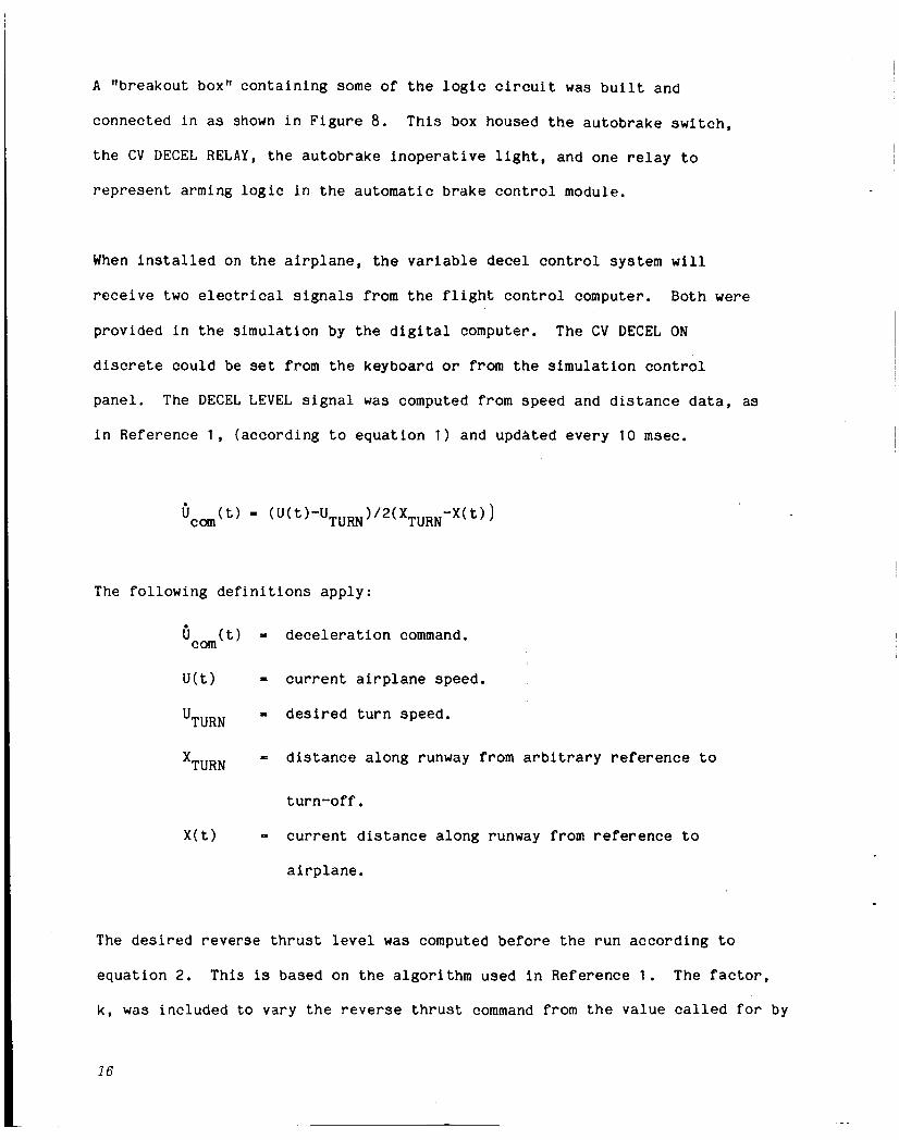
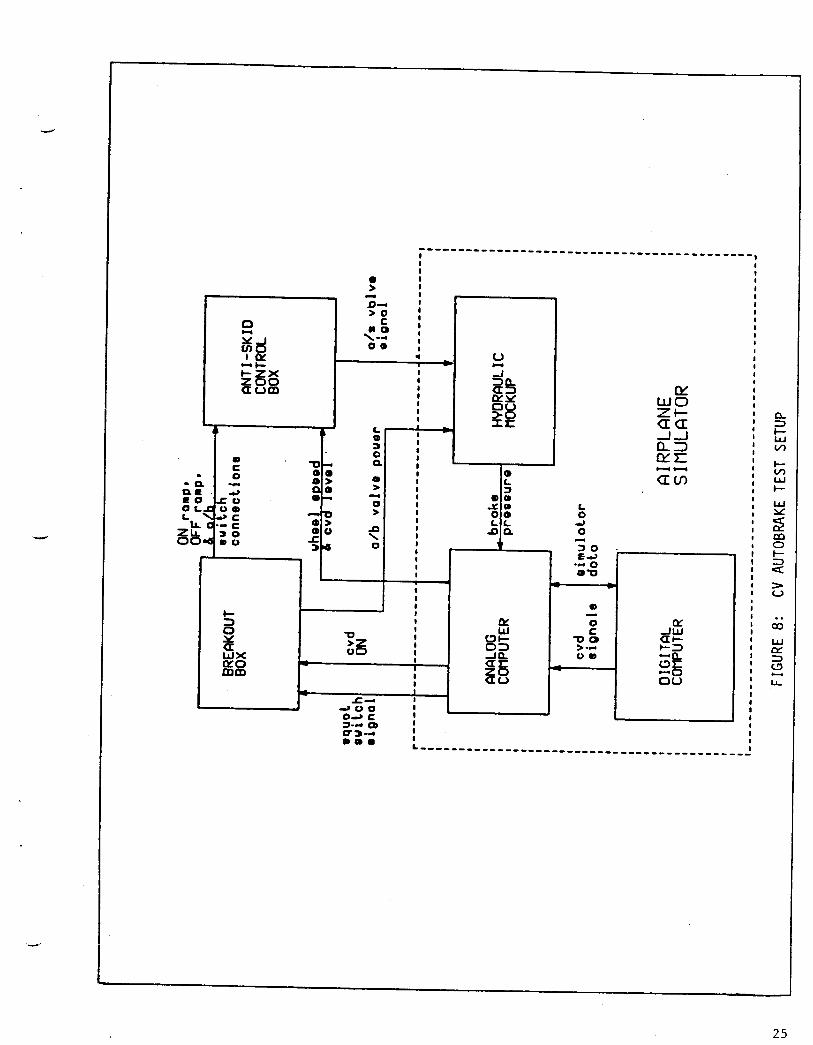
A l lb reakout box" c o n t a i n i n g some of t h e log ic C i r c u i t was b u i l t and
connec ted i n as shown i n F i g u r e 8.
t h e CV DECEL RELAY, t h e a u t o b r a k e i n o p e r a t i v e l i g h t , and o n e r e l a y t o
r e p r e s e n t arming logic i n t h e automatic brake c o n t r o l module.
T h i s box housed t h e a u t o b r a k e swi tch ,
When i n s t a l l e d on the a i r p l a n e , t h e v a r i a b l e decel c o n t r o l sys tem w i l l
r e c e i v e two electrical s i g n a l s from t h e f l i g h t c o n t r o l computer. Both were
provided i n t h e s i r n u l a t i o n by t h e d i g i t a l computer. The CV DECEL ON
discrete c o u l d be set from t h e keyboard or from the s i m u l a t i o n c o n t r o l
p a n e l . The DECEL LEVEL s i g n a l was computed from speed and d i s t a n c e data , as
i n Reference 1 , ( a c c o r d i n g t o e q u a t i o n 1 ) and updated e v e r y 10 msec.
The f o l l o w i n g d e f i n i t i o n s a p p l y :
6 ( t ) - d e c e l e r a t i o n command. COm
'(t) = c u r r e n t a i r p l a n e speed .
= d e s i r e d t u r n speed. 'TURN
= d i s t a n c e a l o n g runway from a r b i t r a r y r e f e r e n c e t o 'TURN
t u r n - o f f .
X ( t ) - c u r r e n t d i s t a n c e a l o n g runway from r e f e r e n c e t o
a i r p l a n e .
The desired r e v e r s e t h r u s t l e v e l was computed before t h e r u n a c c o r d i n g t o
e q u a t i o n 2. T h i s is based on t h e algorithm used i n Refe rence 1 . The factor ,
k , was i n c l u d e d t o v a r y t he r e v e r s e t h r u s t command from t h e v a l u e called f o r by
16

t h e s t o p p i n g c o n d i t i o n s .
r e v e r s e t h r u s t .
The command was l imi t ed t o t h e maximum a v a i l a b l e
2( 1 - T e / t r o l l )
and
ro l l 2 X ~ ~ ~ ~ / ( U o + 'TURN)
The v a r i a b l e s ape d e f i n e d as fo l lows :
F r e v
k
m
"0
"TURN
e '
F~~~~
t ro l l
UR
W
P
'd
r e v e r s e t h r u s t command p e r eng ine .
s c a l i n g factor used t o a l t e r the tes t c o n d i t i o n s .
mass of the a i r p l a n e .
i n i t i a l a i r p l a n e speed.
desired t u r n speed .
time c o n s t a n t of engine r e sponse .
e n g i n e i d l e t h u r s t per eng ine .
e x p e c t e d time from touchdown t o t h e t u r n .
t i re r o l l i n g r e s i s t a n c e factor.
a i r p l a n e weight .
a i r d e n s i t y .
a i r p l a n e wing r e f e r e n c e area.
d r a g c o e f f i c i e n t .
F
1 7
4.2 Test Cond i t ions
The pa rame te r s v a r i e d can be c o n s i d e r e d i n three g roups . The f i rs t g roup
( i n i t i a l speed, t u r n s p e e d and d i s t a n c e t o the t u r n ) is most i m p o r t a n t because
i t d e f i n e s t h e average d e c e l e r a t i o n r e q u i r e d . The second g roup ( t h r u s t l e v e l
and runway mu) has i m p o r t a n t impac t o n t h e a b i l i t y of the b r a k i n g s y s t e m t o
a c h i e v e t ha t d e c e l e r a t i o n .
A 3 - d i g i t c a s e number c l a s s i f i c a t i o n sys t em was a s s i g n e d t o t h e test matrix as
shown i n F i g u r e 9 . The first d i g i t i d e n t i f i e s major classes of c o n d i t i o n s .
For i n s t a n c e , a l l t h e case numbers s t a r t i n g wi th a 4 i d e n t i f y h igh gross we igh t
runs . The l a s t two d i g i t s i d e n t i f y t h e combina t ion of i n i t i a l s p e e d , t u r n
s p e e d , and t u r n d i s t a n c e . Thus , a l l the case numbers end ing w i t h 06 i d e n t i f y
cases w i t h t h e same combina t ion of s p e e d and d i s t a n c e r e q u i r e m e n t s .
The r a n g e of s i m u l a t e d test c o n d i t o n s was based on t h a t o f Re fe rence 1 . The
b a s e l i n e c o n d i t i o n is a 90,000 l b . a i r p l a n e on a d r y runway w i t h no wind, and
t h e t h r u s t command set a c c o r d i n g t o e q u a t i o n 2. The t h r u s t command went from
i d l e t o t h e desired l e v e l one second af ter touchdown, and back t o i d l e when t h e
a i r p l a n e speed was w i t h i n 5 feet/sec of t h e des i red t u r n speed .
of t h e eng ine t o t h i s command was modeled as a first order l a g w i t h a time
c o n s t a n t of 1.3 sec. The i n i t i a l speed is 200 feet p e r s econd (120 k n o t s ) and
t h e d e s i r e d t u r n speed is 110 feet/sec (65 k n o t s ) . The d i s t a n c e from touchdown ,
t o the t u r n o f f is 2300 feet .
The r e s p o n s e
To check out a r ange o f r e q u i r e d d e c e l e r a t i o n s ( r u n s 001 t o 015), i n i t i a l s p e e d
was varied from 110 k n o t s t o 135 k n o t s ; t h e r a n g e of t u r n s p e e d s was between 45
18
k n o t s and 75 k n o t s . D i s t a n c e t o t h e t u r n was v a r i e d from 1800 feet t o 3600
feet , r e s u l t i n g i n r e q u i r e d of ave rage d e c e l e r a t i o n s from 2.6 t o 13.1
feet/sec/sec.
I n most cases, t h e reverse t h r u s t command was set a c c o r d i n g t o e q u a t i o n 1 (as
i n t h e b a s e l i n e case) b u t i n some cases ( r u n s 101 t o 1061, o n l y h a l f t h a t much
t h r u s t was used .
r e v e r s e t h r u s t on t h e a c c u r a c y of t h e sys tem.
t h r u s t makes i t i m p o s s i b l e for t h e b r a k i n g sys t em t o c o n t r o l d e c e l e r a t i o n ) . A
medium range of speed and d i s t a n c e c o n d i t i o n s were r u n for t h e low t h r u s t
test i ng .
These r u n s g i v e a n i n d i c a t i o n of t h e impact of i n a d e q u a t e
(Obvious ly , too much r e v e r s e
Most of t h e c o n d i t i o n s were d r y runway cases, b u t a set of wet runway cases
were s i m u l a t e d ( r u n s 201 to 206). I n t h e s e cases, runway f r i c t i o n was computed
as a f u n c t i o n of a i r p l a n e speed acco rd ing t o T a b l e 2. A medium r a n g e of speed
and d i s t a n c e c o n d i t i o n s were r u n for the wet runway t e s t i n g . I n case 304, t h e
f r i c t i o n l e v e l was set t o . 2 for the e n t i r e run .
The effect of a i r p l a n e weight on system performance was i n v e s t i g a t e d fo r a .
moderate r a n g e of speed and d i s t a n c e c o n d i t i o n s . The b a s e l i n e t e s t i n g was run
a t 90000 l b . l a n d i n g weight . This was v a r i e d t o 70000 l b . ( i n r u n s 504 t o 5 0 9 )
and t o 110000 l b ( i n r u n s 404 to 409). Headwinds and t a i l w i n d s of a b o u t 15
k n o t s were s i m u l a t e d t o e v a l u a t e the i r effect on the d e c e l e r a t i o n c o n t r o l
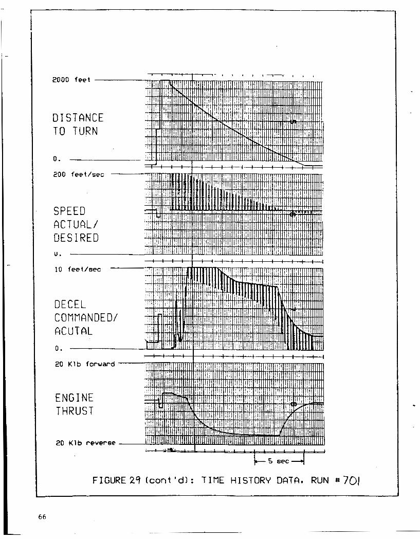
system. These are t h e 600 and 700 series r u n s .
4.3 Test Results
Table 1 i n Figure 9 shows the effectiveness of the system i n each of the test
conditions. The "speed error" t e l l s how close the system came t o achieving the
desired speed a t the t u r n off .
foot /sec . With few exceptions, the error is l e s s than 1
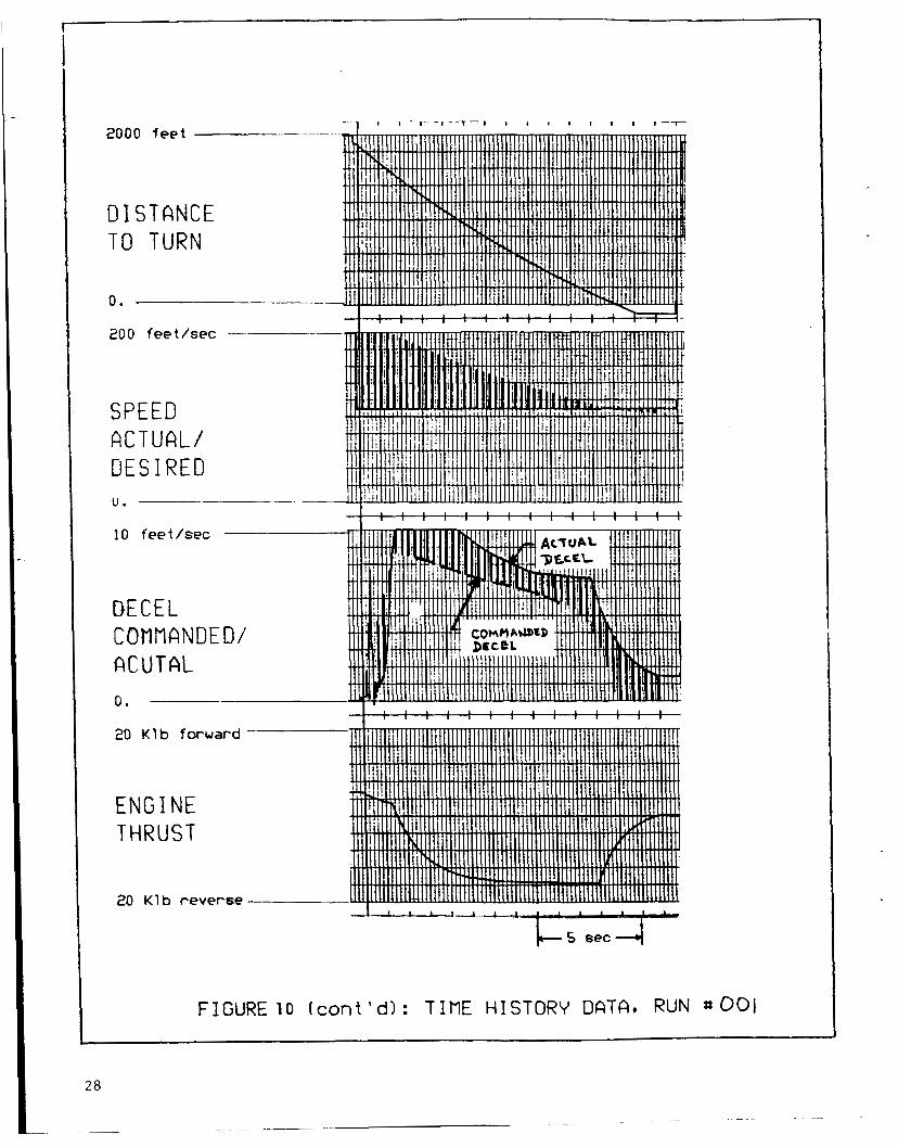
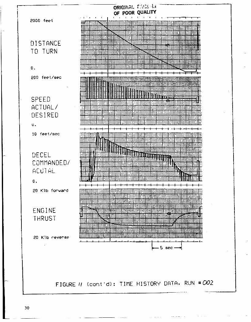
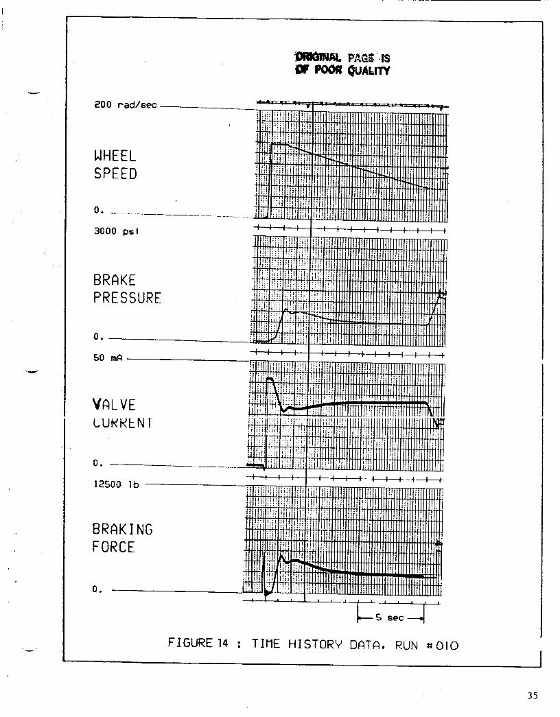
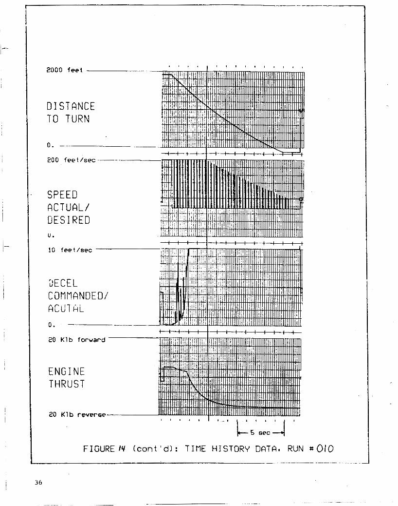
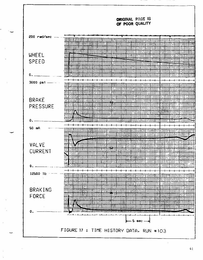
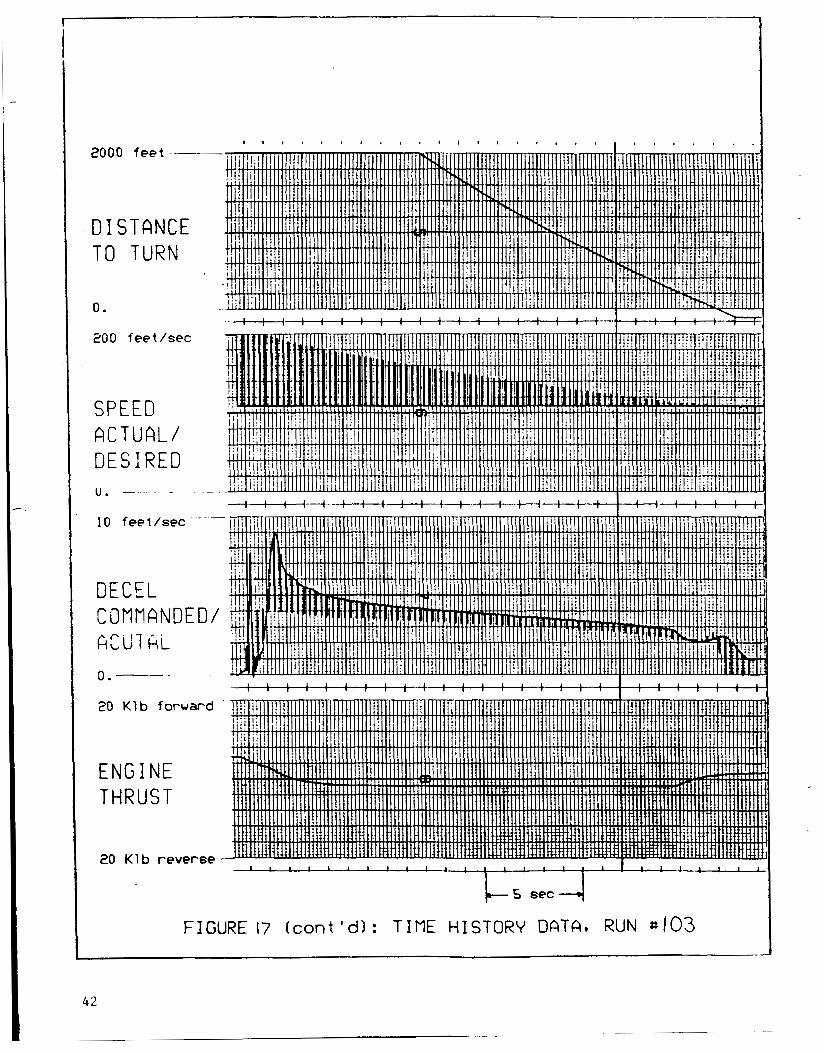
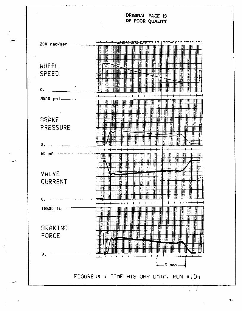
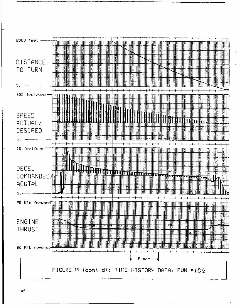
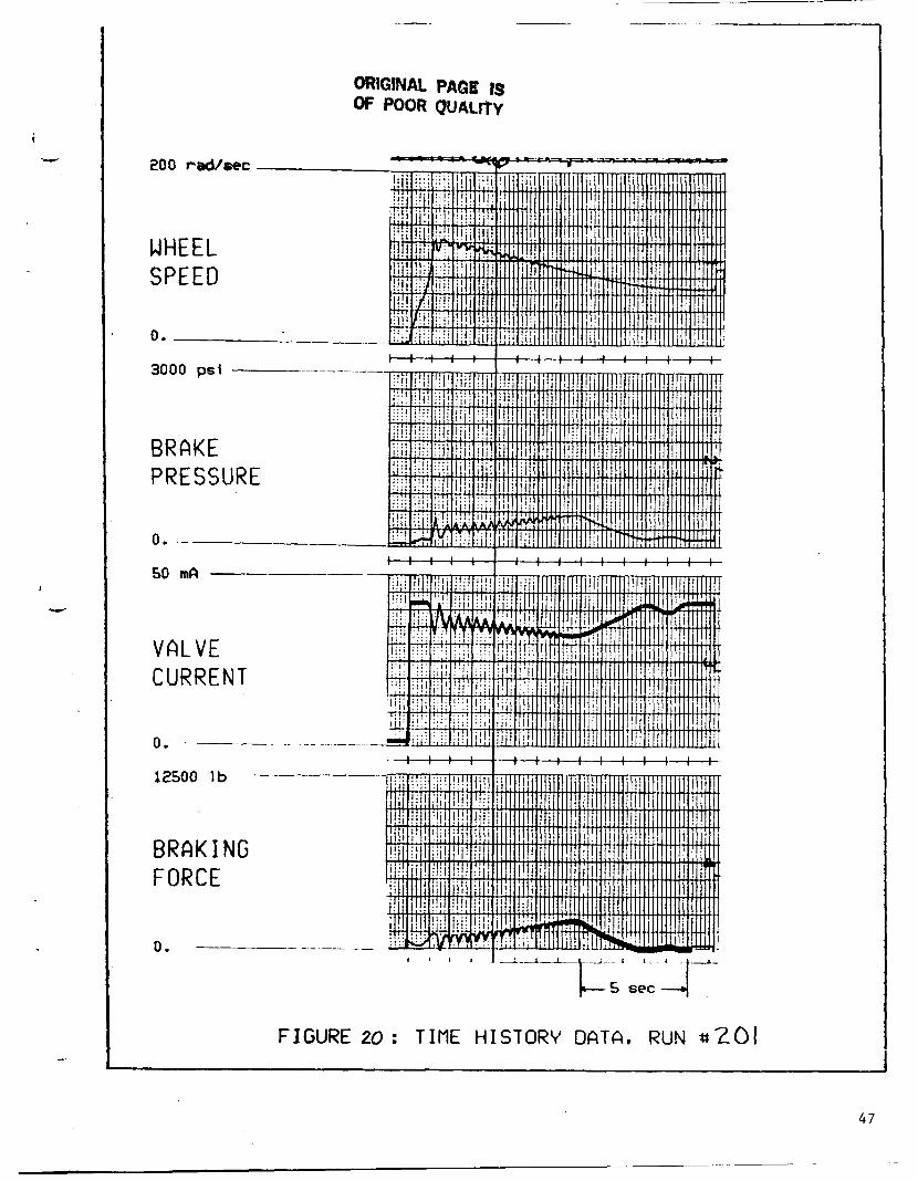
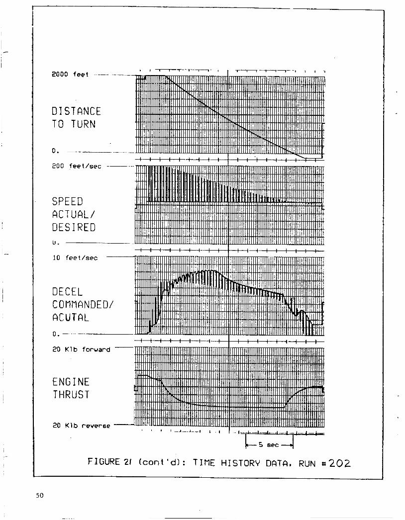
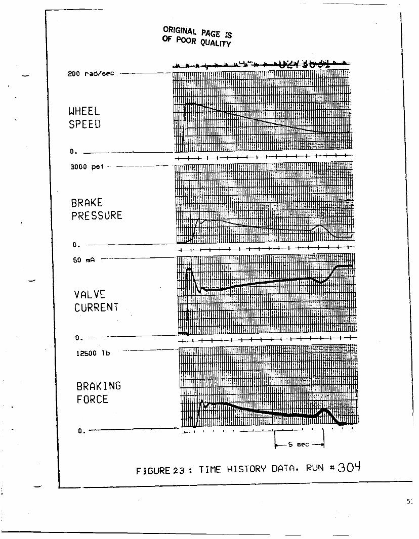
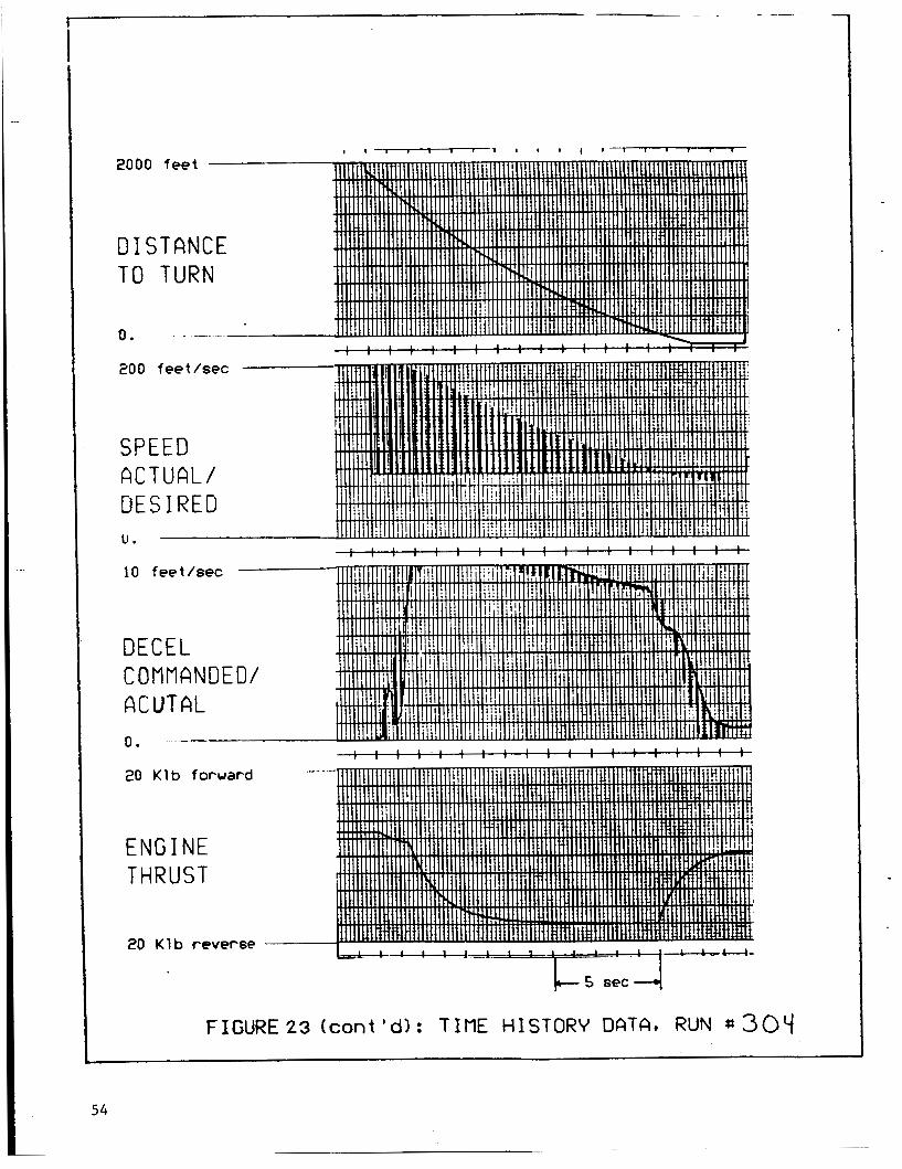
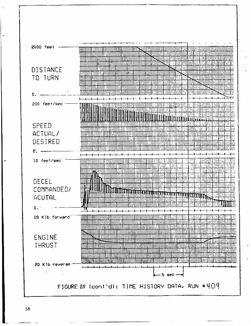
Time history data for selected cases appears i n Figures 10 through 29. The
data was plotted by a s t r i p chart recorder connected t o the simulator.
the recorder channels display multiplexed signals. One channel shows the
desired t u r n speed as a smooth l ine , compared t o the actual airplane speed,
which is a i r c ra f t deceleration as a smooth curve and the decel command level
w i t h the l i ne connected by brief spikes (see Figure 10).
Two of
An overview of the time history data shows the following trends. The airplane
actual deceleration is usually higher than the commanded deceleration and both
decrease w i t h time. The second effect is a resu l t of the f irst ( i . e . i f the
deceleration exceeds the required leve l , the required deceleration is reduced).
Part of the overshoot is due t o a "deceleration t ransient" a t brake
application. Another contributing factor is tha t , for a constant deceleration
command s e t t i n g , deceleration is a function of speed (because of nonlinearity
i n the wheel speed decoding c i r c u i t ) . I n cal ibrat ing the system, i t was deemed
preferable t o have excess deceleration a t h i g h speed, than t o have insuff ic ient
deceleration a t low speed.
20
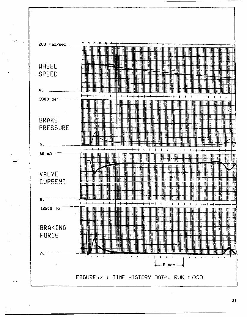
Another prominent feature is that t h e braking force remains a t zero for a
substant ia l portion of most runs. T h i s is because the reverse t h r u s t is
providing enough, or more than enough deceleration. The brake system is
effect ively disengaged and can no longer provide closed loop deceleration
control. The deceleration overshoot a t brake application and the algorithm
used t o compute desired reverse t h r u s t combine t o cause t h i s condition. The
cases i n which the reverse t h r u s t command was reduced from the computed value,
provide a better indication of t h e a b i l i t y of the braking system to control
deceleration than the cases i n which the brakes a re disengaged.
Time history also shows that i f often takes about 2 seconds t o get the brakes
off a f t e r t h e airplane a r r ives a t t h e desired spot on the runway.
Runs 001 through 015 cover a wide range of speed and distance requirements.
Only run 010 shows a large error i n speed a t the t u r n off point. I n that case,
the required deceleration was 1 3 feet/sec/sec. Since the decel command is
limited a t 10 feet/sec/sec. and the reverse t h r u s t command is limited t o 8200
l b . per engine, the system d i d not deliver adequate deceleration.
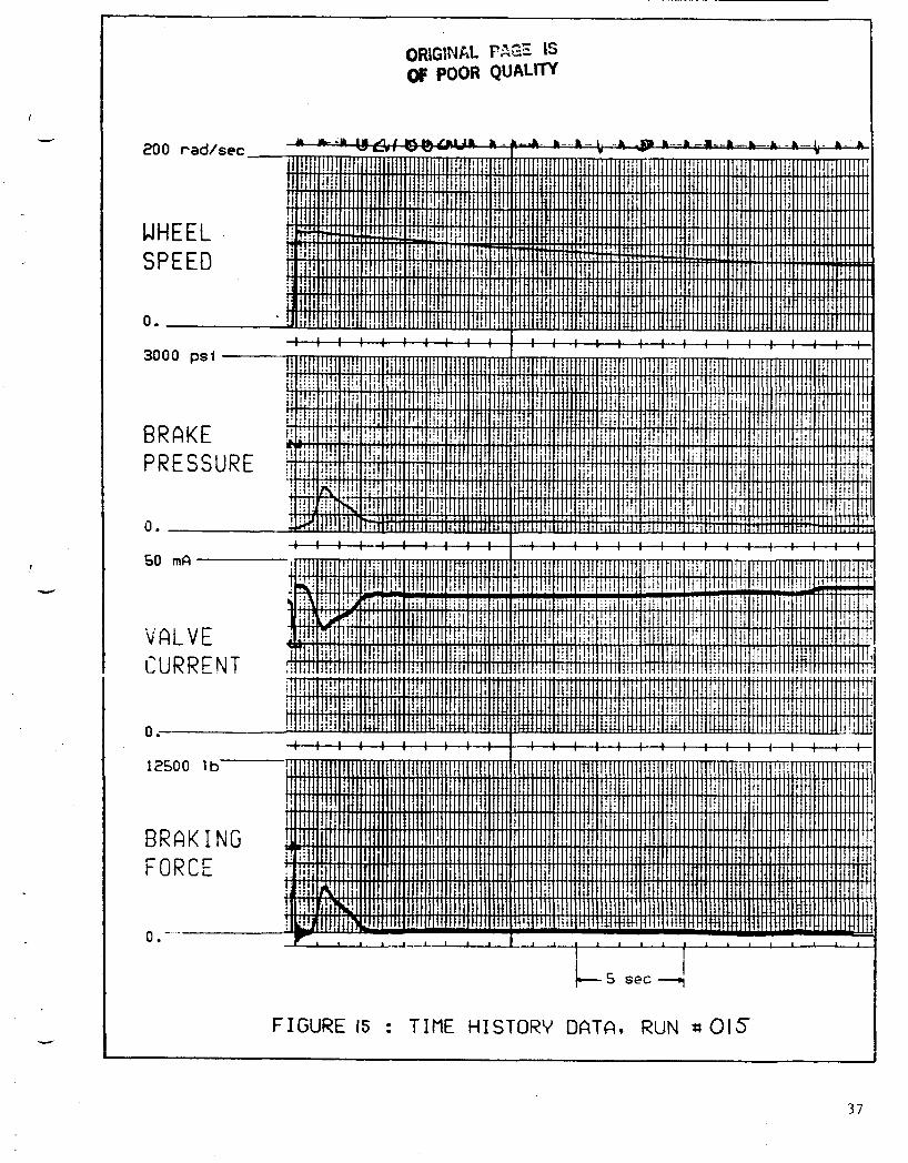
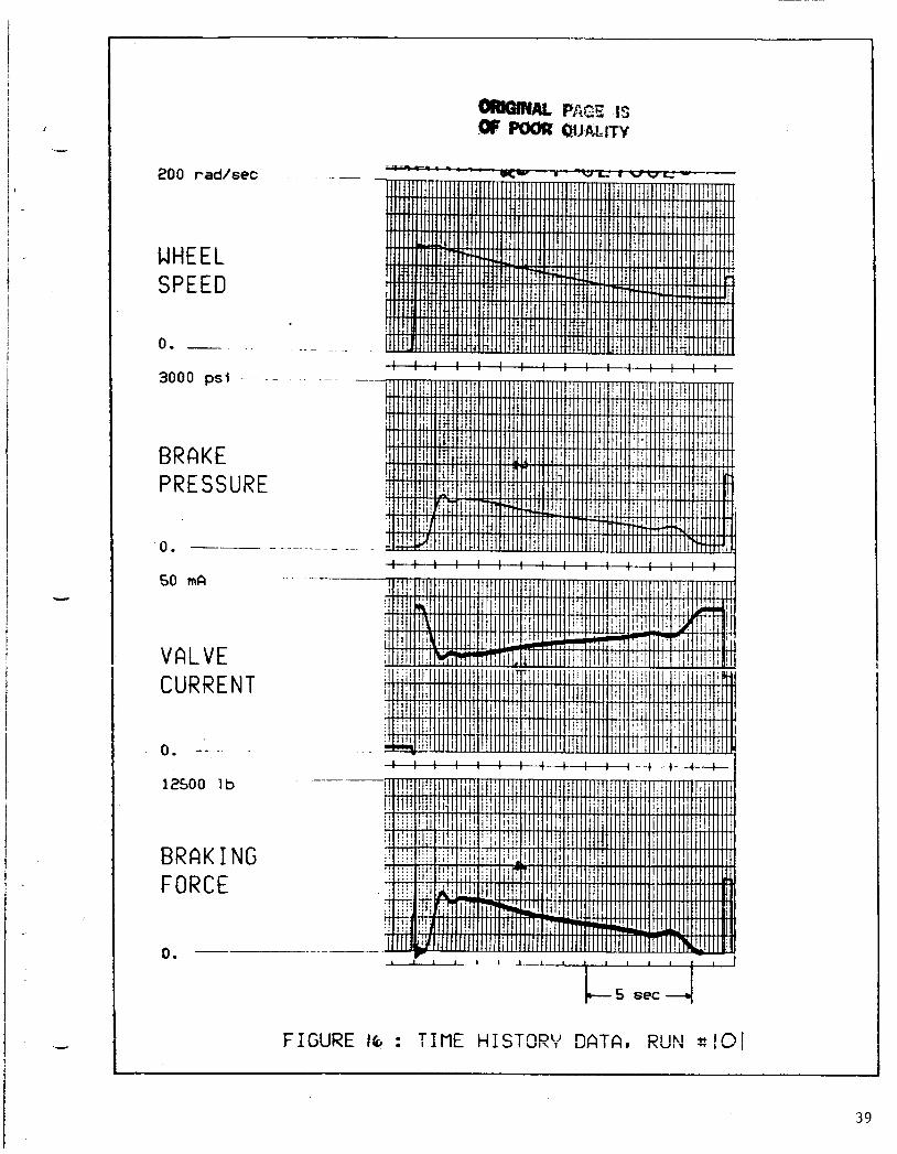
I n r u n s 101 through 106, the commanded reverse t h r u s t was cut by 50% from the
computed value. The speed combinations r u n (see Table 1 , Figure 9 ) required
decelerations between 3.9 and 9.6 feet/sec/sec. I n every case, the speed error
a t the t u r n off was l e s s than 1 footlsec. Comparison of the brake pressure
levels i n these r u n s w i t h those i n t h e previous r u n s having the same speed and
distance combinations, ( r u n s 001 through 006) shows the increased braking
e f fo r t t o compensate for the reduced reverse t h r u s t .
21

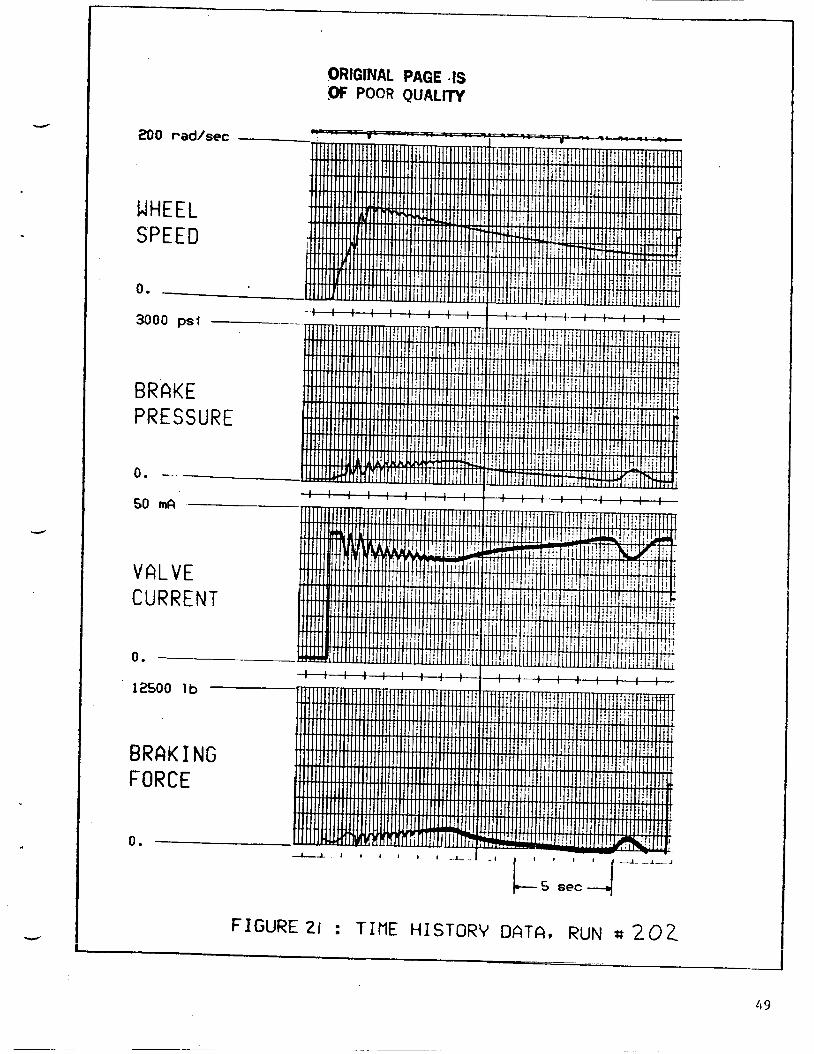
Cases 201 th rough 304 were r u n t o i n v e s t i g a t e t h e s y s t e m performance on
s l i p p e r y runways. The r e q u i r e d d e c e l e r a t i o n s were between 3 . 9 and 9.6
feet/sec/sec. I n o n l y one case was t h e s p e e d e r r o r a t t h e t u r n off
s u b s t a n t i a l l y g r e a t e r t h a n 1 foot/sec. I n t h e other case ( r u n 202 for
example ) , t h e low f r i c t i o n l i m i t e d d e c e l e r a t i o n a t h i g h s p e e d , and t h e a n t i -
s k i d system c o n t r o l l e d t h e brake p r e s s u r e . As t h e runway f r i c t i o n b u i l t up ,
e v e n t u a l l y t h e a u t o b r a k e sys t em took o v e r and b rough t t h e a i r p l a n e t o t h e
des i red speed.
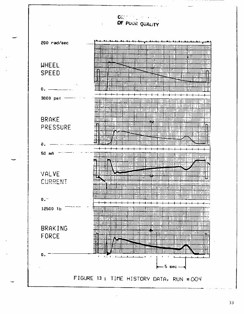
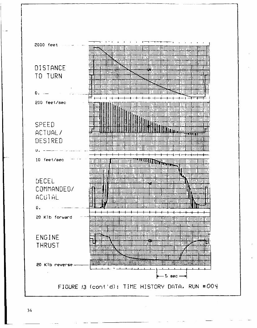
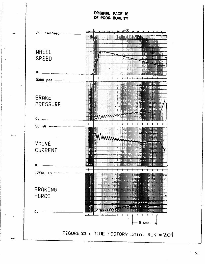
I n run 204, t h e high decel case, maximum a v a i l a b l e r e v e r s e t h r u s t was employed ,
b u t t h e wet runway l i m i t e d t h e b r a k i n g force, and t h e r e q u i r e d d e c e l e r a t i o n was
not ach ieved . Compare t h i s time h i s t o r y data t o r u n 004 ( t h e same speed and
d i s t a n c e combina t ion , o n a d r y runway) and n o t e t h e b r a k i n g e f f o r t r e q u i r e d .
Hun 304 a l s o had t h e same s p e e d and d i s t a n c e combina t ions , and was r u n w i t h a
c o n s t a n t runway mu of .2 ( i n c o n t r a s t t o t he mu v e r s u s s p e e d c u r v e used i n t h e
o t h e r wet runway c a s e s ) . Run 304 looks j u s t l i k e r u n 004, i n d i c a t i n g t h a t .2
is enough mu, i f i t is a v a i l a b l e from t h e s ta r t . F i n a l l y , n o t e t h a t n e a r t h e
end of r u n 204, t h e system cal led for and a c h i e v e d , more d e c e l e r a t i o n t h a n on
t h e d r y runway, b u t i t c o u l d n o t compensate for t h e low d e c e l e r a t i o n a t h i g h
speed .
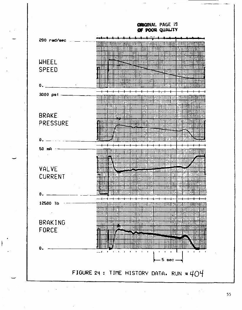
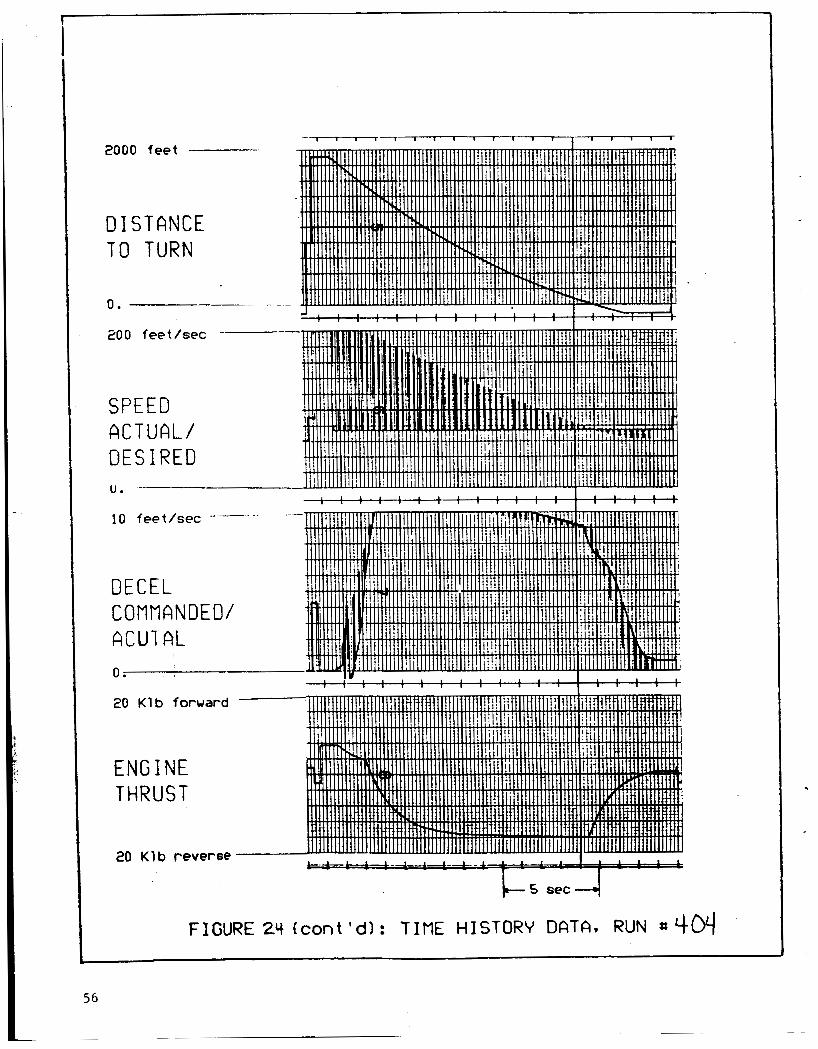
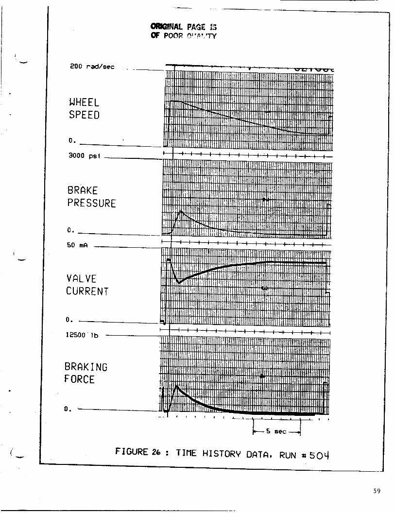
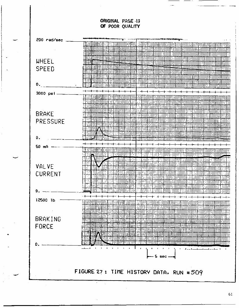
A i r p l a n e weight was shown n o t t o a f fec t t h e sys t em performance. None of t h e
cases run a t 70000 l b . or 110000 l b . r e s u l t e d i n speed errors of s i g n i f i c a n t l y
more t h a n 1 f o o t / s e c . a t t h e t u r n o f f . Speed and d i s t a n c e c o m b i n a t i o n s
r e q u i r i n g d e c e l e r a t i o n s from 3.4 t o 9.6 feet/sec/sec. were r u n a t t h e h i g h
weight ( r u n s 404 t h r o u g h 409) and a t t h e low weight ( r u n s 504 t h r o u g h 5 0 9 ) and
o n l y t h e heavy a i r p l a n e , h i g h d e c e l e r a t i o n case ( r u n 4 0 4 ) t axed t h e System.
22

T h i s is the same speed and distance combination as i n r u n 004 ( a t 90000 lb.)
and 504 ( a t 70000 l b . ) . The effect of the weight variation is seen i n brake
pressure comparisons, because the reverse t h r u s t was s e t t o the l i m i t i n a l l
three cases. I n cases requiring l e s s deceleration (and hence, l e s s reverse
t h r u s t ) , the t h r u s t is not limited, and changes t o r e f l ec t the airplane weight.
.The braking system is not s ignif icant ly affected.
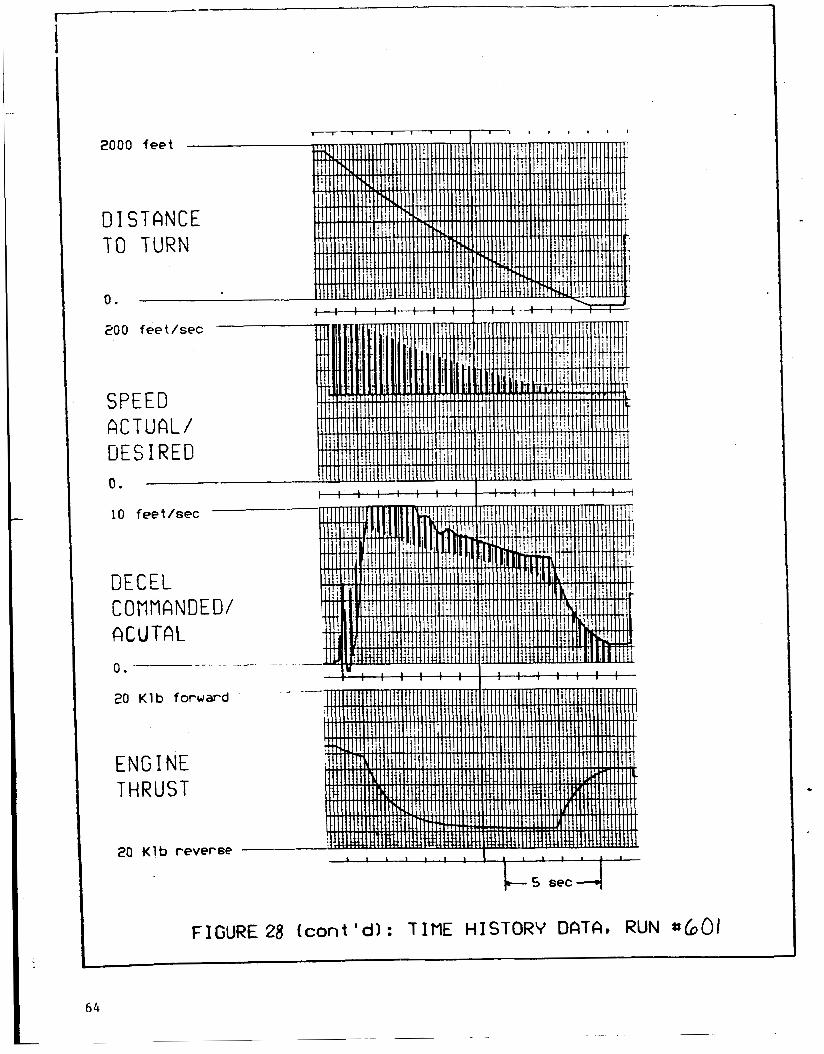
Headwinds and tailwinds of 25 feet lsec. (15 knots) were simulated f o r speed and
distance combinations requiring decelerations between 3.9 and 7.8 feet /sec/sec.
The speed error a t t h e t u r n off i n the tailwind cases ( r u n s 601 t o 603) was
always less than 1 foot/sec. , bu t t he headwinds (in r u n s 701 t o 703) caused low
t u r n off speeds by 3 t o 5 feet isee.
take account of t h e additional drag due t o wind and consequently, cal led for
more reverse t h r u s t than was necessary.
The reverse t h r u s t computation d i d no t

0
n z 0
1%
24
I I
0 I 3 I
H W
a m L 0 3 0
I I 1 I I I I I I I 8 I I I I #
I I I 1 I 4 I I I I I I I I I I I I I I 4 I 1 I I 4 I I I I I I I I I I I I I I I I I I I I 1
25

e W D- cn z IY 3 I-
D W CY
v, w 0
1
0 W w a cn z a: 3 I-
J 3 6 0
U
a
a
I I
a: 0 L1: w w 0 W W a cn
-
I 3 - Z O
0 r u m . - c
> C + I C L u z c c Z f w -
I- m - 30
C U I Y O \I- .-+-
, I
pcma 0 - m . . . 0 m . P
I l l
-cub o m c u . . .
b a o o m ( P W O ' Q - b o . . . . . .
- I I I
cu 9
. . . . . . . . . . . . . . . o o o o o o o o o o o o o o c o o o o o o o o o o o o o o c C O C O 9 C O m Q ~ C O Q a m Q m o d ~ N m . + c u m " m - 4 N m ~ N ( T
-I w 0 0 IT z 0
t- u QI LL
> 3 z 3 IY I- w 3
U
U
a
N -1 W l m a
I
OlA WLL w w v)U n o
w W
26

I
Y 200 radlsec-
WHEEL SPEED
0.
3000 psi-
BRAKE PRESSUR
0 .
50 mA
VRLV CURR
0. --
12500
BRAK FORC
E EN
E
. . .
T
l b ..
I NG E
0. -
FIGURE 10 : TIME HISTORV DATA, RUN # 001
27
2000 feet
0 I ST ONCE T O TURN
0.
200 feet/sec --
SPEED A C T U A L / DES I RED U .
10 feetlsec
DECEL COMMANDE ACUTAL
D/
0.
20 Klb forward
E N G I NE THRUST
20 K l b reverse
FIGURE 10 k o n t ' d ) : TIME HISTORY DATA. RUN ~ 0 0 1

I
4
200 rad/
WHEEL SPEED
0. -
'sec
- 3000 psi
BRAKE PRESSURE
i : : : ! : : : : : : : : : : : : : : :
VALVE CURRENT
1 1 1 1 1 1 1 1 1 1 1 1 1 1 1 1 1 l 1
I " " " " " " " '
12500 l b
BRAK I NG FORCE
0.
FIGURE 11 : TIME HISTORV DATA, RUN #002 __
29
2000 feet
DISTANCE T O TURN
0.
200 feetlsec
SPEED A C JUAL/ DESIRED U .
10 feet/sec
DECEL CUMVANDED/ A C U h i
0. t : : : : ; : : : : : : : : : : : : : : :
20 K1 b forward
ENG I NE THRUST
20 K1 b reverse
FIGURE I ! (cont'dl: TIME HISTORY DATA, RUN -~
30
200
WH SP
0.
rad/sec
EEL EED
3000 psl
BRAKE PRESSURE
0.
VALVE
12500 lb
BRAK I NG FORCE
0.
c - 5 s e c 4
FIGURE 12 : TIME HISTORV DATA. RUN 800003
31

2000 feet
DISTANCE T O TURN
0. - -
200 feet / sec
SPEED A C T U A L / DES IRED U .
IO feetlsec ~
SECEL COMVANDED/ GCU7 HL
0.
20 Klb forward
ENG I NE THRUST
20 Klb reverse 1 1 1 1 1 1 1 1 1 1 1 1 ,
FIGURE 72 (cont'd): T I M E HISTORV DATA. RUN SO03
200 rad/sec .
1 1 . I
WHEEL SPEED
3000 psi -.-.
BRAKE PRESSURE
..
0 . -- ...
V A L V E PI IDDCLIT b U l \ I \ L I . I
0 _-
BRAKING FORCE
0 .
FIGURE 13 : TIME H I S T O R V DATA, RUN ~00' f - -
3 3
2000 feet
DISTANCE T O TURN
0. --
ZOO feet/sec
SPEED A C T U A L / DESIRED u. -
10 feet/sec
-- .
- . .
DECEL COMPANDED/ A X 7 h i
- .- 0.
20 K1 b forward
ENGINE THRUST
20 Klb reverse
FIGURE I3 (cont Id) : T IME HISTORY DATA, RUN *oOcf
34
200 rad/sec
WHEEL SPEED
0 . - .. - __ 3000 psi
BRAKE PRESSURE
0 .
50 mA
Val VF W I IL v L
L U K K t N 1
0. -
12500 l b
BRAK I NG FORCE
-_
0 . 1 , , 1 , , 1 ,
5 sec
I
FIGURE14 : TIME HISTORY DATA, RUN ~ 0 1 0
I 35
2000 feet
D I S T A N C E T O TURN
0.
200 feetlsec -
SPEED ACTUAL/ DES I RED U .
10 feetlsec
DECEL COMtlANDED/ A W 7 h i
0.
20 Klb forward
ENGINE THRUST
20 Klb reverse
I ' I l l 1 1 I I I 1 1 1 - 1
& S set+ FIGURE 14 (cont Id): T I M E HISTORY DATA. RUN ~ O l O
- - -
36
i
1
I
200 rad/sec
WHEEL SPEED
0.
3000 psl
BRAKE PRESSURE
0.
12500 lb-
B R A K I N FORCE
0.- --
G
FIGURE IS : TIME HISTORY DATA, RUN *to15
3 7

!OOO feet
I I S T A N C E ro TURN
3 .
200 feetlsec
SPEED RCTUAL/ DESIRED 0.
10 feetlsec-
'SECEL COMtWNDED A C G I h i
/
0.
20 Klb foruard-
ENG I NE THRUST
I 20 K1 b reverse
5 sec '-1- FIGURE15 ( con t ' d ) : TINE HISTORY DATA, RUN 8015
L
38
-~~ ~~
~
200 rad/sec
WHEEL SPEED
0. - . .
3000 psi
B R A K E P R E S S U R E
0. -
50 mA
VALVE CURRENT
B R A K I N G FORCE
0. -
. ... .
.
__
. .. .
39

2000 feet - . .
DISTANCE T O TURN
.. .
- - ..
200 feet/sec
SPEED A C T U A L / DES I RED u. -
t : : : : : : : : : : : I : : : i 10 feet/sec ~~
DECEL COMMANDED/ ACUTAL 0.
20 Klb forward
ENGINE THRUST
20 Klb reverse I I I 1 1 1 I 4 I I 1 t . L - . I
5 sec
FIGURE 16 (cont'd): TIME HISTORV DATA, RUN 8101
40
200 rad/sec
WHEEL SPEED
0. -
-- .
. - . -
3000 PSI -- -.
BRAKE PRESSURE
0 .
50 mA -
VALVE CURRENT
0.
ORIGWAL PAGE IS OF POOR QUALITY
12500 l b -
BRAKING FORCE
2000
D I S T O
0.
feet -~
ITANCE TURN
200 feet/sec
SPEED A C T U A L / DES I RED
10 feet/sec
DECEL CDRT?ANDED/ G U 7 h i
E N G I NE THRUST
20 K1 b reverse
L s s e c 4
FIGURE 17 (cont'dl: TIME HISTORV DATA, RUN 8103
4 2
200 rad/
WHEEL SPEED
0 - -
'sec
- 3000 PSI
BRAKE PRESSURE
0. -- - - ...
50 mA
VALVE CURRENT
12500 l b -
BRAK I NG FORCE
0 ,
ORiGfNAL PAGE IS OF POOR QUALIW
L 5 s e c 4
FIGURE 18 : TIME HISTORV DATA, RUN a loq
4 3

2000 feet -
D I STANCE T O TURN
0. -. -~
200 feetlsec
SPEED ACTUAL/ DES I RED U.
10 feetlsec _ _ _ -
DECEL CBMI?ANDED/ GCG7 h i 0.
20 K1 b foruard
E N G I NE THRUST
20 K1 b reverse I I I I I I I
5 sec
FIGURE 18 (cont'd): TIME HISTORY DATA, RUN
44

ORIGINAL PAGE ts OF POOR QUALITY
200 rad/s
WHEEL SPEED
;ec
0 - - 3000 PSI -
BRAKE PRESSUR
0.
50 mA -
VALVE CURREN
E
T
0. --
12500 lb -
BRAK I NG FORCE
0.
I FIGURE 19 : TINE HISTORV DATA, RUN SI06 I . - I - I
45
2000 feet -
D I STANCE T O TURN
0. ---
200 feet /sec -
SPEED ACTUAL/ DESIRED u. --
10 feetlsec-
DECEL COMMANDED ACUTAL
20
EF T t
20
Klb for
J G I N E i R U S 1
K l b re\
.ward
rerse 1 I 1 I 1 1 1 1 1 1 1 1 l
FIGURE 19 (cont ' d ) : TIME HISTORY DATA. RUN 8 /06 J *
46
i Y
I
Y
200 rad/sec
WHEEL SPEED
0.
ORIGINAL PACE rs OF POOR QUAlItY
3000 PSI
BRAKE PRESSURE
-- SO mA
V A L V E CURRENT
12500 lb --
BRAK I NG FORCE
FIGURE 20: TIME HISTORY DATA, RUN
47

2000 feet --___
DISTANCE T O TURN
0. -
200 feet/sec
SPEED A C T U A L / DES I REO
10 feetlsec - _ _ _ - -
DECEL COMMANDED/ ACUTAL
20 Klb forward
ENG I NE THRUST
20 Klb reverse
L5 secJ
FIGURE 20 (cont ' d ) : TIME HISTORY DATA. RUN # 201
48
v
-
L
v
ORlGlNAL PAGE *IS IoF POOR QUALITY
FIGURE 21 : TIME HISTORV DATA. RUN st 202
2000 feet
D I S T A N C E T O TURN
0 . - _ _ _
200 feetlsec _ _ _ -
SPEED ACTUAL/ DES I RED U .
10 feethec --
DECEL COMMANDED/ ACUTAL
20 K1 b forward
E N G I NE THRUST
20 K1 b reverse
200 rad/sec -
WHEEL SPEED
3000 psl -
B R A K E P R E S S U R E
0 . -_
V A L V E CURRENT
0.
12500 l b - - . . -
ORIGINAL PAGE rs OF POOR Q u A L l N
1 I , , , , I , , , , , , , ' 1 " ' " " " " ~
. .. ..
B R A K I N G FORCE
0. -
FIGURE22 : TINE HISTORV DATA, RUN 8204
51

2000 feet - -
D I STANCE T O TURN
0. . . . .
200 feet/sec
SPEED A C JUAL/ DES I RED U .
10 feet/sec
DECEL COMMANDED/ QCUTAL 0.
20 Klb foruard
ENG I NE THRUST
20 K1 b reverse
FIGURE22 (cont'd): T I M E HISTORV DATA. RUN
52
200 rad/sec --
WHEEL SPEED
0. .-- 1 , u ! 1 : : : : : : . , , v . Q '
, 1 1 1 1 "
3000 PSI - -
BRAKE PRESSUR
0 . --
- -- I , . . . .
- I . . . . .
50 mA -----
CURRENT
12500 l b .
FIGURE23 : TIME HISTORY DATA. RUN s 3 O q -
5 :
2000 feet
DISTANCE T O T U R N
200 feet/sec
SPEED A C T U A L / DESIRED U .
10 feetlsec -
DECEL COMMANDED ACUTAL 0. --
20 Klb forward
ENG I NE T H R U S T
20 K1 b reverse
k 5 s e c 4
FIGURE 23 (cont Id ) : T I M E HISTORY DATA, RUN 30q
5 4
200 rad/sec .
WHEEL SPEED
0.
3000 PSI -
BRAKE PRESSURE
--
VALVE CURRENT
1 1 1 1 1 1 1 1 1 1 1 1 1 I l l . , , I .
50 mA -
1 1 1 1 1 1 1 1 1 1 1 1 1 1 1
I " " t
0.
12500 l b
BRAK I NG FORCE
0.
FIGUREZY : TIME HISTORV DATA, RUN *rqoLf
55
2000 feet -
0 I STANCE T O TURN
0.
200 feetlsec
SPEED ACTUAL/ DES I RED u. -
10 feet/sec --
DECEL COMMANDED/ G C U 7 AL
..
0.
20 K1 b forward
ENG I NE THRUST
20 K1 b reverse
---r I I I 1 I , 1 1 , , , 1 , ,
k5 s e c 4
FIGURE 2Lt lcont ' d ) : TIME HISTORV DATA, RUN 8 4w

200 radlsec
WHEEL SPEED
0.
ORfGfNAL PAG:" i? OF POOR QUALITY
3000 psi
BRAKE PRESSURE
50 mA
VALVE CURRENT
0. ---- I : : ! : : ! : ! ! ! : ! ! : ! : i f ! ! ! I : ! !
12500 lb --.--
BRAKING FORCE
0.-
FIGURE 25 : TINE HISTORV DATA, RUN * q 0 7
57
2000 feet -
DISTANCE T O TURN
200 feetlsec
SPEED ACTUAL/ DESIRED 0.
10 feetlsec -
DECEL COMPANDED/ ACUTAL
20 K1 b foruard
THR
20 K
ENGINE JST
b reverse
58
I Y
i v
c
.v (
200 rad/sec . .-
WHEEL SPEED
0.
3000 psl
BRAKE PRESSURE
0 .
50 mA
VALVE CURRENT
0.
I C W U Ib
I . . . . . .
FIGURE 26 : TIME HISTORV DATA. RUN *SO‘/ _ _
59

60
2000 feet -
D I S T A N C E T O TURN
. -- 0. -
1 1 - - 1 1 I I I I 1- I - ' ' ' ' ' '
200 feetlsec
SPEED ACTUAL/ DES 1 RED 0.
10 feetlsec
OECEL COMMANDED/ GCUTAL 0.
20 Klb forward
ENGINE THRUST
20 K1 b reverse
FIGURE 2 6 (cont 'd): T I M E HISTORV DATA, RUN asoq
-- _ - -
ORIGINAL PAGE *E OF POOR QUALIN
200 rad/sec
WHEEL SPEED
0.
3000 psl -
BRAKE PRESSURE
V A L V E C U R R E N T
0. ---- 12500 lb --
BRAKING FORCE
0. ---
FIGURE 27 : TIME HISTORV DATA, RUN ~ 5 0 9
61

2000
DlS T O
0. -
feet
I T A N C TURN
200 feet/sec
SPEED A C T U A L / DES I R E D
-... . u. -
10 feetlsec -
DECEL COMMANDED G C U T N
20 K l b forward
ENGINE THRUST
20 Klb reverse
I I , , , , l--T--T--l 1 1 - - - T - - r - - 7 1 - 1 I , I , , I I - -r-
FIGURE27 (cont 'd ) : TIME HISTORV DATA. RUN =507
6 2

I
Y
ORIGINAL PAGE -:S OF POOR QUALITY
200 rad/sec -
WHEEL SPEED
0.
- -w
3000 psl
B R A K E PRESSURE
0.
50 mA
VALVE CURRENT
0.
B R A K I N G FORCE
FIGURE28: T IME HISTORV DATA. RUN * b o { -
63
64
2000 feet -
DISTANCE T O TURN
0.
200 feetlsec
SPEED ACTUAL/ DESIRED
10 feetlsec
DECEL COMMANDE ACU TAL
. n -
D /
.
20 K1 b forward
ENG I NE THRUST
20 K1 b reverse
b 5 s e c d
FIGURE 28 (cont Id): T I M E HISTORV DATA, RUN ~ 6 0 1
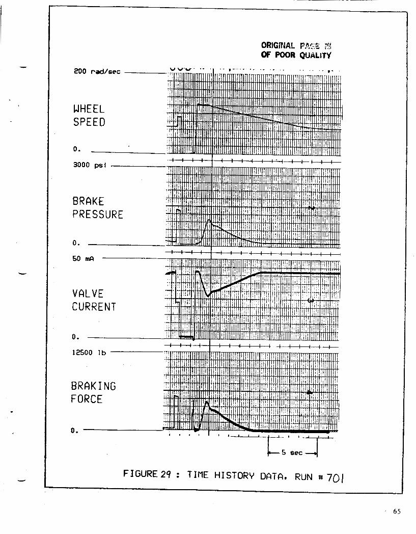
FIGURE29 : TIME HISTORV DATA, RUN 8 701 I
6 5
2000 feet
DISTAN T O TUR
0 . -
CE N
200 feetlsec
SPEED A C JUAL/ DES I RED U.
10 feetlsec
DECEL COMVANDE ACUPAL 0.
D/
20 K1 b foruard
Tt
20
ENG I NE RUST
Klb reverse - - I - . , 1 I * , , I I -
5 sec
FIGURE29 (cont'dl: T I M E HISTORY DATA. RUN "701
66
5.0 CONCLUSIONS
The m o d i f i c a t i o n s des igned under t h i s c o n t r a c t and p r e s e n t e d i n t h i s r e p o r t
w i l l e n a b l e t h e research f l i g h t c o n t r o l computer t o c o n t r o l d e c e l e r a t i o n
d u r i n g l a n d i n g r o l l - o u t i n such a way as t o b r i n g t h e a i r c ra f t t o a desired
speed a t a p a r t i c u l a r s p o t on t h e runway f o r t h e purpose e x e c u t i n g
a u t o m a t i c , h i g h speed turn-off 's .
The r e q u i r e d m o d i f i c a t i o n s are summarized as f o l l o w s :
A R M I N G LOGIC
Add a new s e t t i n g (VAR f o r v a r i a b l e , i n a d d i t i o n t o t h e
c u r r e n t OFF, M I N , MED, MAX s e t t i n g s ) t o t h e a u t o b r a k e c o n t r o l
swi tch i n t he forward f l i g h t deck, and a relay for sa fe ty l o g i c .
DECELERATION CONTROL
Modify t h e s e l e c t e d d e c e l e r a t i o n c o n t r o l cards i n t h e
a n t i - s k i d box t o respond t o t he c o n t i n u o u s l y v a r i a b l e
d e c e l e r a t i o n command.
AFT FLIGHT DECK AND INTERFACE
Add t h e VAR s e t t i n g t o t h e autobrake cont re l switch aiid add
67

a corresponding channel t o t h e communication network between
a f t and forward f l i g h t decks.
Two aspects of the performance of t h e proposed continuously variable
decleration control system m u s t be emphasized. Due t o t h e time response of
the deceleration control loop, i t takes two seconds t o re lease the brakes
a f t e r the deceleration command goes t o zero. To avoid braking d u r i n g the
turn-off, i t is recommended t h a t algorithm used t o compute t h e deceleration
command take account of t h i s de lay . Secondly, the system does not provide
v e r y precise deceleration control. The discrepancy between the command and
the actual deceleration w i l l often exeed 1 foot/sec/sec. However, the
system implemented i n these simulated t e s t s does provide the desired r e s u l t s
i n terms of speed and distance.
68
REFERENCES
( 1 ) Pines, S., "Terminal Area Automatic Navigation, Guidance, and Control
Research Using the Microwave Landing System (MLS)", - NASA CR-3451,
August, 1981.
69

Standard Bibliographic Page
Report No. 12. Government Accession No.
NASA CR-178155
AUTOMATIC BRAKING SYSTEM MODIFICATION FOR THE ADVANCE1 TRANSPORT OPERATING SYSTEMS (ATOPS) TRANSPORTATION SYSTEMS RESEARCH VEHICLE (TSRV)
Title and Subtitle
James J. Coogan Author( s)
__ , Performinn Organization Name and Address Boeing Commercial Airplane Company A Division of The Boeing Company Seattle, Washington 98124
2 . Sponsoring Agency Name and Address National Aeronautics and Space Administration Washington, DC 20546
3. Recipient's Catalog No.
5. Report Date
October 1986 6. Performing organization Code
- 8. Performing Organization Report No.
D6-38012 10. Work Unit No.
11. Contract or Grant No.
NASl-17635 -- 13. Type of Report and Period Covered
Contractor Report - 14. Sponsoring Agency Code
505-45-33-04 5 . Supplernentary Notes Langley Technical Monitor: James C. Young Final Report - Task 7
6 Abstract Modifications were designed for the B-737-100 Research Aircraft autobrake system hardware of the Advanced Transport Operating Systems (ATOPS) Program at Langley Research Center. These modifications will allow the on-board flight control computer to control the aircraft deceleration after landing to a continuously variable level for the purpose of executing automatic high speed turn-offs from the runway. tested in simulated stopping conditions. Test results, for various aircraft weights, turnoff speed, winds, and runway conditions show that the turnoff speed are achieved generally with errors less than 1 ft/sec.
A bread board version of the proposed modifications was built and
17. Key Words (Suggested by Authors(s))
Automatic Braking Automatic Control
. . ~ ____.--~_ - I!]. Security CIassif.(of this report) 20. Seciirit,
- 18. Distribution Statement
Unclassified - Unlimited
Unclassified 73 A04 - _- -. _ _ 1- -Vnclassified --I- -. - ~ -1- - -- -- - -
For sale by the National Technical Inlormsriori Service, Springfield, Virgiiiia 22161 N 4 d A Langley k'orm 61 (June 1985)