nasa habitat demonstration unit (hdu) deep space … · nasa habitat demonstration unit (hdu) deep...
TRANSCRIPT

American Institute of Aeronautics and Astronautics
1
NASA Habitat Demonstration Unit (HDU) Deep Space Habitat Analog
A. Scott Howe, PhD1 Jet Propulsion Laboratory, California Institute of Technology, 4800 Oak Grove Drive, Pasadena, California 91109
Kriss J. Kennedy2 NASA Johnson Space Center, Houston, Texas, 77058, USA
Tracy Gill3 NASA Kennedy Space Center, Florida, 32899, USA
and
NASA Deep Space Habitat subsystem leads4
The NASA Habitat Demonstration Unit (HDU) vertical cylinder habitat was established as a exploration habitat testbed platform for integration and testing of a variety of technologies and subsystems that will be required in a human-occupied planetary surface outpost or Deep Space Habitat (DSH). The HDU functioned as a medium-fidelity habitat prototype from 2010-2012 and allowed teams from all over NASA to collaborate on field analog missions, mission operations tests, and system integration tests to help shake out equipment and provide feedback for technology development cycles and crew training. This paper documents the final 2012 configuration of the HDU, and discusses some of the testing that took place. Though much of the higher-fidelity functionality has ‘graduated’ into other NASA programs, as of this writing the HDU, renamed Human Exploration Research Analog (HERA), will continue to be available as a volumetric and operational mockup for NASA Human Research Program (HRP) research from 2013 onward.
Nomenclature
A/DMM = Airlock/Dust Mitigation Module AES = NASA Advanced Exploration Systems project ATHLETE = All-Terrain Hex-Limbed Extra-Terrestrial Explorer robotic mobility system COTS = Commercial Off-The-Shelf CRIM = Commercial Refrigeration Incubation Module CTB = Cargo Transfer Bag DAQ = Data Acquisition Unit DCIS = Dual-Chamber Hybrid Inflatable Suitlock
1 DSH Management Team: Design Integration Lead, Senior Systems Engineer, [email protected] 2 DSH Management Team: [former] HDU Project Manager, Space Architect, [email protected] 3 DSH Management Team: Systems Integration Lead, [email protected] 4 DSH Subsystem Leads include: Mike Amoroso & Chris Chapman (JSC – Integration), Shelley Baccus (JSC – Crew Accommodations), Melissa Borrego (JSC – Hygiene), Richard Barido (JSC – ECLS), Danny Carrejo (JSC – Habitat Test Bed), David Coan & Natalie Mary (JSC – EVA), John Cornwell (JSC – Thermal), Cindy Evans & Mike Calaway (JSC – Geoscience), Patrick George & Tony Colozza (GRC – PM&D), Robert Howard & Jonathan Dory (JSC – Human Systems Integration), Dennis Lawler & Lui Wang (JSC – Software), Mike Miller (KSC – Communications), David Mittman (JPL – Telerobotics), Adam Rawlin & Maxwell Haddock (JSC – Avionics), Kristina Rojdev (JSC – Wireless Instrumentation), Russell Smith (LaRC – Structures), Raymond Wheeler (KSC – Food Production).
Dow
nloa
ded
by S
cott
How
e on
Sep
tem
ber
16, 2
013
| http
://ar
c.ai
aa.o
rg |
DO
I: 1
0.25
14/6
.201
3-54
36
AIAA SPACE 2013 Conference and Exposition
September 10-12, 2013, San Diego, CA
AIAA 2013-5436
Copyright © 2013 by the American Institute of Aeronautics and Astronautics, Inc. The U.S. Government has a royalty-free license to exercise all rights under the copyright claimed herein for Governmental purposes. All other rights are reserved by the copyright owner.
American Institute of Aeronautics and Astronautics
2
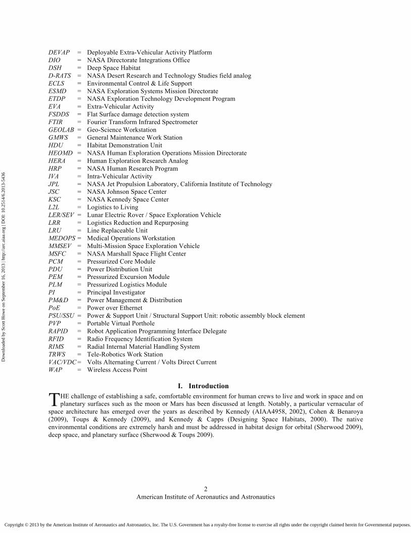
DEVAP = Deployable Extra-Vehicular Activity Platform DIO = NASA Directorate Integrations Office DSH = Deep Space Habitat D-RATS = NASA Desert Research and Technology Studies field analog ECLS = Environmental Control & Life Support ESMD = NASA Exploration Systems Mission Directorate ETDP = NASA Exploration Technology Development Program EVA = Extra-Vehicular Activity FSDDS = Flat Surface damage detection system FTIR = Fourier Transform Infrared Spectrometer GEOLAB = Geo-Science Workstation GMWS = General Maintenance Work Station HDU = Habitat Demonstration Unit HEOMD = NASA Human Exploration Operations Mission Directorate HERA = Human Exploration Research Analog HRP = NASA Human Research Program IVA = Intra-Vehicular Activity JPL = NASA Jet Propulsion Laboratory, California Institute of Technology JSC = NASA Johnson Space Center KSC = NASA Kennedy Space Center L2L = Logistics to Living LER/SEV = Lunar Electric Rover / Space Exploration Vehicle LRR = Logistics Reduction and Repurposing LRU = Line Replaceable Unit MEDOPS = Medical Operations Workstation MMSEV = Multi-Mission Space Exploration Vehicle MSFC = NASA Marshall Space Flight Center PCM = Pressurized Core Module PDU = Power Distribution Unit PEM = Pressurized Excursion Module PLM = Pressurized Logistics Module PI = Principal Investigator PM&D = Power Management & Distribution PoE = Power over Ethernet PSU/SSU = Power & Support Unit / Structural Support Unit: robotic assembly block element PVP = Portable Virtual Porthole RAPID = Robot Application Programming Interface Delegate RFID = Radio Frequency Identification System RIMS = Radial Internal Material Handling System TRWS = Tele-Robotics Work Station VAC/VDC = Volts Alternating Current / Volts Direct Current WAP = Wireless Access Point
I. Introduction HE challenge of establishing a safe, comfortable environment for human crews to live and work in space and on planetary surfaces such as the moon or Mars has been discussed at length. Notably, a particular vernacular of
space architecture has emerged over the years as described by Kennedy (AIAA4958, 2002), Cohen & Benaroya (2009), Toups & Kennedy (2009), and Kennedy & Capps (Designing Space Habitats, 2000). The native environmental conditions are extremely harsh and must be addressed in habitat design for orbital (Sherwood 2009), deep space, and planetary surface (Sherwood & Toups 2009).
T
Dow
nloa
ded
by S
cott
How
e on
Sep
tem
ber
16, 2
013
| http
://ar
c.ai
aa.o
rg |
DO
I: 1
0.25
14/6
.201
3-54
36
Copyright © 2013 by the American Institute of Aeronautics and Astronautics, Inc. The U.S. Government has a royalty-free license to exercise all rights under the copyright claimed herein for Governmental purposes. All other rights are reserved by the copyright owner.
American Institute of Aeronautics and Astronautics
3
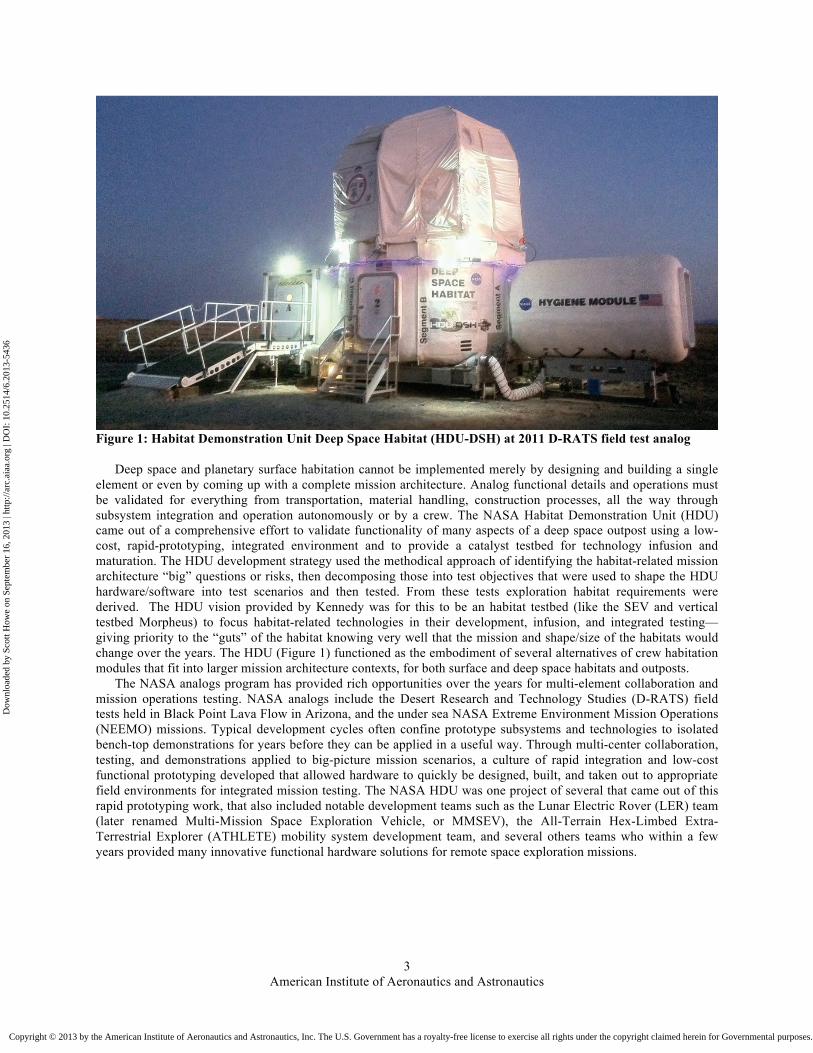
Figure 1: Habitat Demonstration Unit Deep Space Habitat (HDU-DSH) at 2011 D-RATS field test analog
Deep space and planetary surface habitation cannot be implemented merely by designing and building a single element or even by coming up with a complete mission architecture. Analog functional details and operations must be validated for everything from transportation, material handling, construction processes, all the way through subsystem integration and operation autonomously or by a crew. The NASA Habitat Demonstration Unit (HDU) came out of a comprehensive effort to validate functionality of many aspects of a deep space outpost using a low-cost, rapid-prototyping, integrated environment and to provide a catalyst testbed for technology infusion and maturation. The HDU development strategy used the methodical approach of identifying the habitat-related mission architecture “big” questions or risks, then decomposing those into test objectives that were used to shape the HDU hardware/software into test scenarios and then tested. From these tests exploration habitat requirements were derived. The HDU vision provided by Kennedy was for this to be an habitat testbed (like the SEV and vertical testbed Morpheus) to focus habitat-related technologies in their development, infusion, and integrated testing—giving priority to the “guts” of the habitat knowing very well that the mission and shape/size of the habitats would change over the years. The HDU (Figure 1) functioned as the embodiment of several alternatives of crew habitation modules that fit into larger mission architecture contexts, for both surface and deep space habitats and outposts.
The NASA analogs program has provided rich opportunities over the years for multi-element collaboration and mission operations testing. NASA analogs include the Desert Research and Technology Studies (D-RATS) field tests held in Black Point Lava Flow in Arizona, and the under sea NASA Extreme Environment Mission Operations (NEEMO) missions. Typical development cycles often confine prototype subsystems and technologies to isolated bench-top demonstrations for years before they can be applied in a useful way. Through multi-center collaboration, testing, and demonstrations applied to big-picture mission scenarios, a culture of rapid integration and low-cost functional prototyping developed that allowed hardware to quickly be designed, built, and taken out to appropriate field environments for integrated mission testing. The NASA HDU was one project of several that came out of this rapid prototyping work, that also included notable development teams such as the Lunar Electric Rover (LER) team (later renamed Multi-Mission Space Exploration Vehicle, or MMSEV), the All-Terrain Hex-Limbed Extra-Terrestrial Explorer (ATHLETE) mobility system development team, and several others teams who within a few years provided many innovative functional hardware solutions for remote space exploration missions.
Dow
nloa
ded
by S
cott
How
e on
Sep
tem
ber
16, 2
013
| http
://ar
c.ai
aa.o
rg |
DO
I: 1
0.25
14/6
.201
3-54
36
Copyright © 2013 by the American Institute of Aeronautics and Astronautics, Inc. The U.S. Government has a royalty-free license to exercise all rights under the copyright claimed herein for Governmental purposes. All other rights are reserved by the copyright owner.

American Institute of Aeronautics and Astronautics
4
Self-propelled robotic platform with underslung pressure modules
Figure 2: Precedent: planetary surface robotic construction system, with parametric hybrid inflatable module (left), and robotic platform (right), in Howe & Howe (2000)
Figure 3: Precedent: robotic construction site layout showing material handling and work cells (Howe & Howe 2000), illustrates the importance of ordering the environment into a machine-readable layout for automated placement
Stowed pressure module with Deployed pressure module with inflatable cylinder
Self-propelled robotic platform Parametric module placed by robotic platform in work cell 30 degree radial grid Robotic work cell Pressurized connecting tunnels
Dow
nloa
ded
by S
cott
How
e on
Sep
tem
ber
16, 2
013
| http
://ar
c.ai
aa.o
rg |
DO
I: 1
0.25
14/6
.201
3-54
36
Copyright © 2013 by the American Institute of Aeronautics and Astronautics, Inc. The U.S. Government has a royalty-free license to exercise all rights under the copyright claimed herein for Governmental purposes. All other rights are reserved by the copyright owner.

American Institute of Aeronautics and Astronautics
5
Figure 4: docking of pressurized modules using robotic ATHLETE assembler (photos by A. Scott Howe)
Tri-ATHLETE robots docked to Power & Support Unit (PSU) pallet PSU functions as a power source (either through solar arrays, batteries, or fuel cells) Payload (Hab module, etc) is permanently attached to PSU and is independent from Tri-ATHLETEs Tri-ATHLETEs will separate and return to PSU to recharge batteries
Figure 5: ATHLETE capacity for separating into two "Tri-ATHLETEs", for the purpose of lifting and placing payloads
From the big-picture view automated construction, docking, and assembly of pressure modules was validated using remotely teleoperated robotic construction equipment, assuming that elements, payloads, and equipment are delivered to a destination based on a transportation manifest schedule. An operational mission scenario using a full suite of functional equipment, in-situ crews, and ground crews was executed to validate operations and find gaps. Then on an element by element level, working subsystems integrated into a functional whole were tested in operations in an iterative rapid-prototyping development schedule.
Previous discussions about the HDU have been presented from various perspectives, including overall concept (Kennedy et. al. 2010b; Kennedy et. al. 2011), system integration (Gill et. al. 2010a; Gill et. al. 2011), integration process (Gill, Merbitz, Kennedy, Tri, Howe 2010), test operations (Tri, Kennedy, Gill, Howe 2010c), and planning
Dow
nloa
ded
by S
cott
How
e on
Sep
tem
ber
16, 2
013
| http
://ar
c.ai
aa.o
rg |
DO
I: 1
0.25
14/6
.201
3-54
36
Copyright © 2013 by the American Institute of Aeronautics and Astronautics, Inc. The U.S. Government has a royalty-free license to exercise all rights under the copyright claimed herein for Governmental purposes. All other rights are reserved by the copyright owner.

American Institute of Aeronautics and Astronautics
6
and logistics (Tri et. al. 2011), and detailed discussions about subsystems and HDU technologies by various subsystem teams. In this article, we give an overview of the overall design integration concept, an account of how the HDU came to be, and a description of the various functional subsystems as they were in the final 2012 configuration.
Figure 6: placement of modules can be accomplished in sequence using separate Tri-ATHLETE sub-vehicles
II. Robotic Construction of Remote Human Outposts
Increasingly, design must not only include a detailed description of what a finished artifact should look like and function, but also the entire process for how it is manufactured and put together. The design of the construction and assembly process is especially important for multiple elements brought together for a deep space habitat or planetary surface outpost. One important assumption for constructing remote human outposts is that the very environment needed for a human crew to survive is being assembled, and until that environment is functional and capable of supporting life, it may not be practical economically or materially to have a human present. In other words, where construction activity normally uses a variety of human skills and labor to process and assemble the materials and structure components, for space missions the cost of maintaining a pressurized safe environment for a crew member does not practically allow us to have that person function as a construction worker. Instead, it becomes practical to use robots and autonomous precursor assets to first assemble the outpost, then allow crew to launch only after their safety is guaranteed by a functioning life support system and comfortable volume that will be dependable until the end of the mission.
Automated construction and robotic assembly of structures (Howe 2000) will dictate form, massing, mobility, interfaces, transportation, and launch manifests. Robotic assembly systems can be characterized on a spectrum – on one end are passive elements assembled and connected to each other using robotic agents, and at the other end of the spectrum all the elements are innately robotic and assemble themselves (Howe 2006; Howe 2007). The outposts and habitats described in this article employ robotic assemblers on passive pressure vessels and other elements.
Some precedent planetary surface robotic construction systems have been proposed, where wheeled mobility systems carry underslung pressurized modules with hard cap ends and mid-expandable inflatable cylinders (Figure 2), placing them adjacent to each other in sequence (Figure 3) to gradually build up an outpost (Howe, Howe 2000). The Constellation surface architecture lunar outpost robotic construction system was designed with a similar robotic assembler for the purpose of downloading modules from flat-topped landers and placing them in desired configurations in relation to each other.
In a 2008 Moses Lake, Washington demonstration two All-Terrain Hex-Limbed Extra-Terrestrial Explorer (ATHLETE) mobility platform functioned as robotic assemblers to dock multiple pressure modules together, via local and remote control (Figure 4). However, in that iteration, the ATHLETE platforms were permanently attached to the habitation modules and could not be detached for reuse on other tasks.
As the Constellation Lunar Outpost design progressed, it became apparent that the ATHLETE mobility system needed to have a capacity for separation so that an assembly sequence could be accomplished by a single robotic assembler. The ATHLETE platform was redesigned to divide into two “Tri-ATHLETE” vehicles and a rectangular utility pallet (Figure 5). With the split body ATHLETE assembler robot, a habitat module could be lifted off the top of an Altair lander, lowered to the surface, and placed at a desired location and still allow the ATHLETE sub-vehicles to continue to bring more modules in sequence for outpost build-up (Figure 6).
Dow
nloa
ded
by S
cott
How
e on
Sep
tem
ber
16, 2
013
| http
://ar
c.ai
aa.o
rg |
DO
I: 1
0.25
14/6
.201
3-54
36
Copyright © 2013 by the American Institute of Aeronautics and Astronautics, Inc. The U.S. Government has a royalty-free license to exercise all rights under the copyright claimed herein for Governmental purposes. All other rights are reserved by the copyright owner.
American Institute of Aeronautics and Astronautics
7
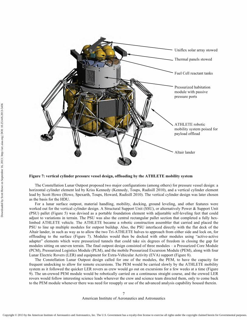
Uniflex solar array stowed Thermal panels stowed Fuel Cell reactant tanks Pressurized habitation module with passive pressure ports ATHLETE robotic mobility system poised for payload offload Altair lander
Figure 7: vertical cylinder pressure vessel design, offloading by the ATHLETE mobility system
The Constellation Lunar Outpost proposed two major configurations (among others) for pressure vessel design: a horizontal cylinder element led by Kriss Kennedy (Kennedy, Toups, Rudisill 2010), and a vertical cylinder element lead by Scott Howe (Howe, Spexarth, Toups, Howard, Rudisill 2010). The vertical cylinder design was later chosen as the basis for the HDU.
For a lunar surface outpost, material handling, mobility, docking, ground leveling, and other features were worked out for the vertical cylinder design. A Structural Support Unit (SSU), or alternatively Power & Support Unit (PSU) pallet (Figure 5) was devised as a portable foundation element with adjustable self-leveling feet that could adjust to variations in terrain. The PSU was also the central rectangular pallet section that completed a fully hex-limbed ATHLETE vehicle. The ATHLETE became a robotic construction assembler that carried and placed the PSU to line up multiple modules for outpost buildup. Also, the PSU interfaced directly with the flat deck of the Altair lander, in such as way as to allow the two Tri-ATHLETE halves to approach from either side and lock on, for offloading to the surface (Figure 7). Modules would then be docked with other modules using “active-active adapter” elements which were pressurized tunnels that could take six degrees of freedom in closing the gap for modules sitting on uneven terrain. The final outpost design consisted of three modules – a Pressurized Core Module (PCM), Pressurized Logistics Module (PLM), and the mobile Pressurized Excursion Module (PEM), along with four Lunar Electric Rovers (LER) and equipment for Extra-Vehicular Activity (EVA) support (Figure 8).
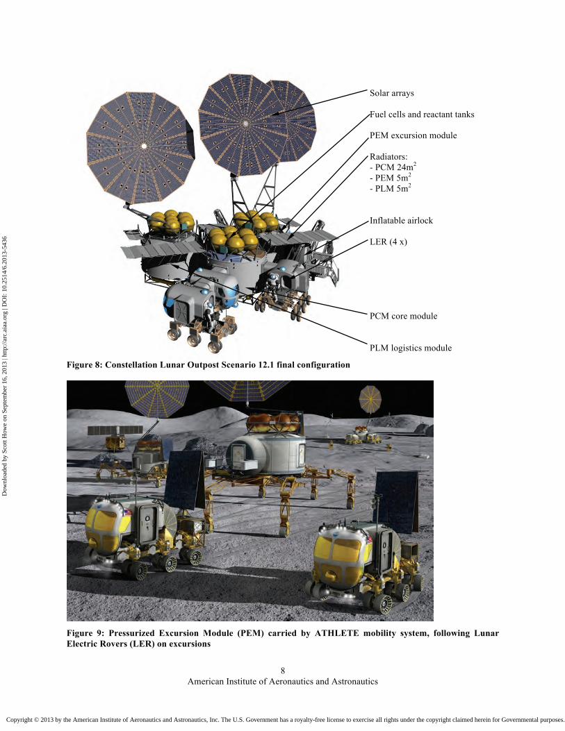
The Constellation Lunar Outpost design called for one of the modules, the PEM, to have the capacity for frequent undocking to allow for remote excursions. The PEM would be carried slowly by the ATHLETE mobility system as it followed the quicker LER rovers as crew would go out on excursions for a few weeks at a time (Figure 9). The un-crewed PEM module would be robotically carried on a continuous straight course, and the crewed LER rovers would follow interesting science leads wherever the crew and science team directed them, only to come back to the PEM module whenever there was need for resupply or use of the advanced analysis capability housed therein.
Dow
nloa
ded
by S
cott
How
e on
Sep
tem
ber
16, 2
013
| http
://ar
c.ai
aa.o
rg |
DO
I: 1
0.25
14/6
.201
3-54
36
Copyright © 2013 by the American Institute of Aeronautics and Astronautics, Inc. The U.S. Government has a royalty-free license to exercise all rights under the copyright claimed herein for Governmental purposes. All other rights are reserved by the copyright owner.
American Institute of Aeronautics and Astronautics
8
Solar arrays Fuel cells and reactant tanks PEM excursion module Radiators: - PCM 24m2 - PEM 5m2 - PLM 5m2 Inflatable airlock LER (4 x) PCM core module PLM logistics module
Figure 8: Constellation Lunar Outpost Scenario 12.1 final configuration
Figure 9: Pressurized Excursion Module (PEM) carried by ATHLETE mobility system, following Lunar Electric Rovers (LER) on excursions
Dow
nloa
ded
by S
cott
How
e on
Sep
tem
ber
16, 2
013
| http
://ar
c.ai
aa.o
rg |
DO
I: 1
0.25
14/6
.201
3-54
36
Copyright © 2013 by the American Institute of Aeronautics and Astronautics, Inc. The U.S. Government has a royalty-free license to exercise all rights under the copyright claimed herein for Governmental purposes. All other rights are reserved by the copyright owner.
American Institute of Aeronautics and Astronautics
9
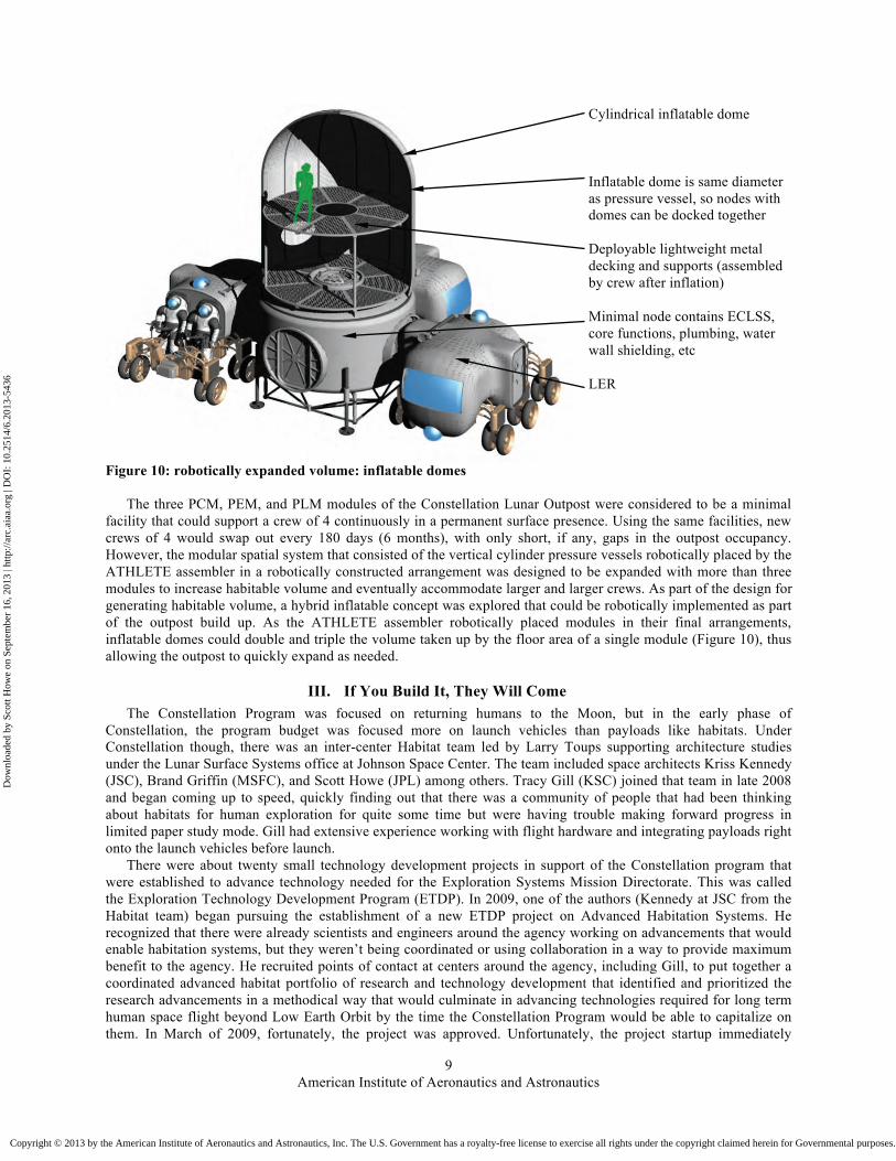
Cylindrical inflatable dome Inflatable dome is same diameter as pressure vessel, so nodes with domes can be docked together Deployable lightweight metal decking and supports (assembled by crew after inflation) Minimal node contains ECLSS, core functions, plumbing, water wall shielding, etc LER
Figure 10: robotically expanded volume: inflatable domes
The three PCM, PEM, and PLM modules of the Constellation Lunar Outpost were considered to be a minimal facility that could support a crew of 4 continuously in a permanent surface presence. Using the same facilities, new crews of 4 would swap out every 180 days (6 months), with only short, if any, gaps in the outpost occupancy. However, the modular spatial system that consisted of the vertical cylinder pressure vessels robotically placed by the ATHLETE assembler in a robotically constructed arrangement was designed to be expanded with more than three modules to increase habitable volume and eventually accommodate larger and larger crews. As part of the design for generating habitable volume, a hybrid inflatable concept was explored that could be robotically implemented as part of the outpost build up. As the ATHLETE assembler robotically placed modules in their final arrangements, inflatable domes could double and triple the volume taken up by the floor area of a single module (Figure 10), thus allowing the outpost to quickly expand as needed.
III. If You Build It, They Will Come
The Constellation Program was focused on returning humans to the Moon, but in the early phase of Constellation, the program budget was focused more on launch vehicles than payloads like habitats. Under Constellation though, there was an inter-center Habitat team led by Larry Toups supporting architecture studies under the Lunar Surface Systems office at Johnson Space Center. The team included space architects Kriss Kennedy (JSC), Brand Griffin (MSFC), and Scott Howe (JPL) among others. Tracy Gill (KSC) joined that team in late 2008 and began coming up to speed, quickly finding out that there was a community of people that had been thinking about habitats for human exploration for quite some time but were having trouble making forward progress in limited paper study mode. Gill had extensive experience working with flight hardware and integrating payloads right onto the launch vehicles before launch.
There were about twenty small technology development projects in support of the Constellation program that were established to advance technology needed for the Exploration Systems Mission Directorate. This was called the Exploration Technology Development Program (ETDP). In 2009, one of the authors (Kennedy at JSC from the Habitat team) began pursuing the establishment of a new ETDP project on Advanced Habitation Systems. He recognized that there were already scientists and engineers around the agency working on advancements that would enable habitation systems, but they weren’t being coordinated or using collaboration in a way to provide maximum benefit to the agency. He recruited points of contact at centers around the agency, including Gill, to put together a coordinated advanced habitat portfolio of research and technology development that identified and prioritized the research advancements in a methodical way that would culminate in advancing technologies required for long term human space flight beyond Low Earth Orbit by the time the Constellation Program would be able to capitalize on them. In March of 2009, fortunately, the project was approved. Unfortunately, the project startup immediately
Dow
nloa
ded
by S
cott
How
e on
Sep
tem
ber
16, 2
013
| http
://ar
c.ai
aa.o
rg |
DO
I: 1
0.25
14/6
.201
3-54
36
Copyright © 2013 by the American Institute of Aeronautics and Astronautics, Inc. The U.S. Government has a royalty-free license to exercise all rights under the copyright claimed herein for Governmental purposes. All other rights are reserved by the copyright owner.

American Institute of Aeronautics and Astronautics
10
deferred from FY10 to FY13 to support the ramp up of the budget profile of Constellation Program, primarily focused on the launch vehicles.
Not fazed by this setback, Kennedy recognized he had the beginning of a good team with common interests that had just come together to build the excellent proposal for the ETDP project on Advanced Habitation Systems, and he wanted to find a way to capitalize on that momentum. In another path-finding area at JSC, engineers and astronauts were working on the LER prototype lunar rover using a learning-by-doing methodology by rapid prototyping systems and then testing them (Craig 2011). Howe, another member of Toups’ Habitat team, had also in parallel been doing hands-on prototyping on robotic construction hardware and demonstration as a member of the ATHLETE development team. Kennedy took a cue from their progress and decided to push this new team in that direction. In April 2009, Kennedy and Gill pulled on the team that had helped with the ETDP proposal and discussed the viability of combining existing efforts using the collaborative Center’s Internal Research & Development (IR&D) funding approach to build a habitat prototype. The idea was to start a project using no dedicated funding and leverage the work already being performed by Center IR&D, other ETDP projects, and innovation projects funded at the various centers and coordinate those separate efforts. The centers were each doing unique projects and had specific skills and expertise, and the team believed that they could partner and collaborate these efforts and package them into a viable habitat testbed demonstrator. The new team wanted to provide an environment for focused development and technology infusion by creating a “battle rhythm” of testing on a yearly or semi-yearly basis. The team used Human Space Flight (HSF) design reference missions (DRM) studies to identify the high level architectural and operations questions to drive the configurations they wanted to assess and the operational scenarios within which the habitat demonstrator would operate.
The idea was to build a Habitat Demonstration Unit that would serve not only to look at the systems and architecture needed for habitation but also serve as a platform for technology maturation. There was a lot of initial excitement and enthusiasm among the team because this looked like something that could actually be accomplished and the new team could get something from almost nothing by establishing a collaboration. However, the biggest obstacle was that the team needed dedicated funding to be able to actually build a habitat shell to host this activity.
The next steps involved putting together a vision with goals and begin a virtual road show to build consensus and gather support. In May of 2009, The new HDU team presented to the Directorate Integration Office (DIO) Exploration Systems Mission Directorate (ESMD) what each of the partner centers could bring to the table and create a product greater than the sum of all its individual contributions. The team sold the notion that instead of having all the projects sitting on tables and benches at the separate centers, there could be an operational test bed that was an integrated platform where the various team members could start to meld those separate systems into an overall habitation system. Additionally, some of the innovators who developed these systems would start to collaborate with others around the agency with the same interests and begin to work together on new proposals and advancements. After presenting this story and the cost estimate for what was needed to build the 5 meter diameter shell of a habitat based on the Lunar Surfaces Systems architecture, Doug Craig of ESMD DIO agreed to provide $400k of seed funding for the development of the shell, and the team was off and running. Thus the new HDU team conveyed the message from the movie Field of Dreams, “If you build it, they will come.” So the team got the go-ahead to build the habitat, and now they needed to get the partners to develop the systems and come to the demonstrator for integration. From this intial seed investment, the HDU team went from a powerpoint concept to an operational habitat testbed part of an integrated mult-element test in the the desert within one year—at a total value of over $7.5m.
In June of 2009, Gill traveled to JSC to meet with Kennedy, and they were joined by Terry Tri, also of the JSC Engineering Directorate. Tri and Kennedy had worked together on habitation projects in the past, and Tri managed some facility and labor resources that could help with integration at JSC. At that kickoff meeting, the new HDU management team defined goals for what they thought they could reasonably accomplish in a fiscal year and some tentative goals for follow-on years. Importantly, they decided to be aggressive and pushed to develop an operational habitat system that could be deployed for testing during the NASA Desert Research and Technology Studies (D-RATS) field analogs that would start in August 2010.
Howe (JPL), who had been participating for several years in the D-RATS field exercises as part of the ATHLETE development team was added to the new HDU management team shortly thereafter. Howe had been co-inventor of the split Tri-ATHLETE system for robotic construction, had come up with the original vertical cylinder pressure vessel configuration that the HDU was to be based on, and was Principal Investigator (PI) in charge of the two JPL Microhabs that ATHLETE used as habitat payloads. The Microhabs had been designed by Jaret Matthews (JPL) and were not meant to actually be habitable. However, as part of the atmosphere of the rapid-prototyping environment that the D-RATS analogs fostered, Kennedy decided to take advantage of the availability of the Microhabs to get an early presence at the D-RATS 2009 field exercises, to help usher in the participation of the
Dow
nloa
ded
by S
cott
How
e on
Sep
tem
ber
16, 2
013
| http
://ar
c.ai
aa.o
rg |
DO
I: 1
0.25
14/6
.201
3-54
36
Copyright © 2013 by the American Institute of Aeronautics and Astronautics, Inc. The U.S. Government has a royalty-free license to exercise all rights under the copyright claimed herein for Governmental purposes. All other rights are reserved by the copyright owner.

American Institute of Aeronautics and Astronautics
11
HDU the following year. Under Toups’ Habitat team, Kennedy assigned Howe to begin designing ways to convert logistics packaging into internal outfitting, in a “Logistics-2-Living” (Howe, Howard 2010) approach that could be demonstrated in one of the Microhabs (Figure 11) during D-RATS 2009. Howe also had experience in setting up direct digital control systems between CAD representations of physical structures (Howe 1997), so in parallel he directed digital monitoring and control specialists from JSC to outfit the Microhab (Figure 12) with a variety of remote instruments that could be monitored from operations mission control during the desert operation (Howe, Hong, Hunkins, Hafermalz, Kennedy, Toups 2010). During the 2009 D-RATS field tests the instrument-packed Logistics-2-Living Microhab was merely a side show to the main mission, but succeeded in its purpose of being an introductory piece of hardware for the HDU 2010 debut. The same Microhab later was repurposed as a hygiene module in subsequent years.
Cargo netting CTBs in launch configuration CTB stiffeners reused as outfitting structure Unfolded CTB used as partition CTBs used as cabinets, desks, and furniture
Figure 11: "Logistics-2-Living" outfitting of Microhab at D-RATS 2009
On the surface the goal of building an operational habitat system in one fiscal year seemed reasonable, but when the team started to think about designing and building the structure and then outfitting that structure with basic subsystems for lighting, power, avionics, thermal control, etc., and then putting in operational work stations, it started to seem like a tall order. An internal joke among the team was that if they could build the shell and put pretty posters inside showing what the team wanted to do and sent that to D-RATS, it would be quite an achievement. Joking aside, the team strategy selected a laboratory configuration from the architecture studies that would represent the “exploration excursion mode” of 2 rovers with this unit away from the lunar outpostfor the first campaign. The 2010 session of D-RATS was planned for Black Point Lava Flow where two Space Exploration Vehicle (SEV) rovers would operate together along with the full scale habitat prototype, now called the Habitat Demonstration Unit (HDU), to allow for a 14-21 day mission. A graphic example of the proposed lunar architecture under evaluation at the D-RATS 2010 campaign is depicted in Figure 9, known as the Pressurized Excursion Module (PEM). As the name implies, the application for the PEM during lunar excursions is to provide research and habitation functionality in a mobile outpost for excursion missions.
To meet this aggressive objective for participating in D-RATS 2010, the HDU management team stremlined integration strategies and a management approach that was adapted for a rapid prototyping project.
Dow
nloa
ded
by S
cott
How
e on
Sep
tem
ber
16, 2
013
| http
://ar
c.ai
aa.o
rg |
DO
I: 1
0.25
14/6
.201
3-54
36
Copyright © 2013 by the American Institute of Aeronautics and Astronautics, Inc. The U.S. Government has a royalty-free license to exercise all rights under the copyright claimed herein for Governmental purposes. All other rights are reserved by the copyright owner.

American Institute of Aeronautics and Astronautics
12
Ethernet Remote control power switcher Ethernet hub Mini PC Temperature monitors Voltage sensors CO2 / humidity monitor Light controller (behind) Power Supply Unit (PSU) rechargeable battery pack Tropos modem (behind) Package air conditioner (analog for ECLSS) LED light power supply
Figure 12: Microhab interior equipment details (Howe, Hong, Hunkins, Hafermalz, Kennedy, Toups 2010)
IV. HDU-PEM Analog Field Prototype 2010
The HDU was developed from a multi-center rapid prototyping tiger team brought together to quickly design, build, and test technologies that will be required for deep space long-duration human exploration missions. Drawing upon years of habitat design experience from multi-center experts, the HDU rapidly came together as a functional prototype field habitat. The HDU shell was manufactured in eight shell slices at Langley Research Center levaraging the funding from ESMD DIO. Designing the shell to be built in slices would not be a prudent choice for a flight article, but it was the right choice for a habitat testbed due to the urgency of the build, the robustness required, and the fact the team wasn’t building an actual pressure vessel. Those slices were shipped to the Johnson Space Center in two shipments, one in December 2009 and the other in January 2010, for assembly and then outfitting with the various PEM systems for the 2010 D-RATS campaign. The original concept was to manufacture all the slices and then ship to JSC for assembly prior to installing any system hardware. Early planning schedules showed that the team might begin integration of the hardware within the shell sections before the shell was complete, but the shell manufacturing team was so successful that the shell was fully assembled and ready for integration in late February 2010 at the time systems were starting to become ready for installation.
The HDU shell slices were a resin infused composite fiberglass structure and each of the slices has a steel rib on either end to attach it to the next slice. Thus there is a double steel “C-shaped” rib at the joint of each slice to slice interface. The ribs were also designed with attach points for secondary structure and pass-throughs for cables and air circulation. The shell slices were made from one common mold that was modified for the variations of a smooth slice or a slice with a door opening. Using one mold was one of the keys to be able to build the shell quickly. The smooth slices also included one slice that had a window opening and thus required a slight modification to the mold. To minimize down time in modifying the mold, the HDU team optimized the production by making several smooth slices and then the slices with door openings and the one with a window. Examples of an HDU rib and the mold for the shell slices are seen in Figure 13.
The shell sections were designated for hardware installation per the proposed layout of HDU PEM Systems as seen in Figure 14. This layout reflects the original two dimensional layout plan which was greatly enhanced by the three dimensional CAD model. The layout consisted of four quadrants with the General Maintenance Work Station, the Extravehicular Suit Maintenance area, a Medical Operations workstation, and a Geology Laboratory (Geo-Lab) area. In addition to the layout of the four quadrants, the installation of all the support systems such as avionics, thermal, lighting, communications, and environmental sensors had to be planned.
Dow
nloa
ded
by S
cott
How
e on
Sep
tem
ber
16, 2
013
| http
://ar
c.ai
aa.o
rg |
DO
I: 1
0.25
14/6
.201
3-54
36
Copyright © 2013 by the American Institute of Aeronautics and Astronautics, Inc. The U.S. Government has a royalty-free license to exercise all rights under the copyright claimed herein for Governmental purposes. All other rights are reserved by the copyright owner.

American Institute of Aeronautics and Astronautics
13
The other main factor in the development schedule was a system by system installation progression where follow-on systems depended on earlier ones, such as power, for their operation. The virtual representation of the HDU-PEM layout, used during the integration process, from the CAD integration activities is pictured in Figure 15.
Integration tasks require a lot of coordination among the integration team and hardware developers, so the schedule was constantly maintained and updated to optimize the limited time available for integration and test prior to deployment for dry runs and D-RATS. Some of the more challenging tasks during the actual integration phase were the application of foam insulation and the installation, wiring of subsystems underneath the floor level of the HDU, and the modification of an existing airlock simulator to work with the HDU-PEM. Various scenes during the actual HDU-PEM integration from February - March 2010 can be seen in Figure 16.
Figure 13: steel rib (left) and shell mold (right) manufactured at NASA Langley Research Center
Additional structures HDU shell structure manufactured in eight sections Plain sections alternating with hatch door sections Window section
Figure 14: HDU Pressurized Excursion Module layout
Dow
nloa
ded
by S
cott
How
e on
Sep
tem
ber
16, 2
013
| http
://ar
c.ai
aa.o
rg |
DO
I: 1
0.25
14/6
.201
3-54
36
Copyright © 2013 by the American Institute of Aeronautics and Astronautics, Inc. The U.S. Government has a royalty-free license to exercise all rights under the copyright claimed herein for Governmental purposes. All other rights are reserved by the copyright owner.
American Institute of Aeronautics and Astronautics
14
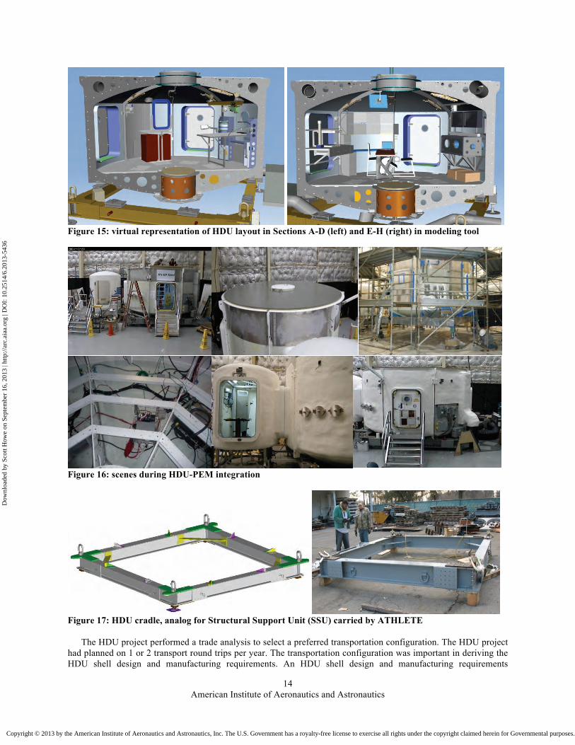
Figure 15: virtual representation of HDU layout in Sections A-D (left) and E-H (right) in modeling tool
Figure 16: scenes during HDU-PEM integration
Figure 17: HDU cradle, analog for Structural Support Unit (SSU) carried by ATHLETE
The HDU project performed a trade analysis to select a preferred transportation configuration. The HDU project had planned on 1 or 2 transport round trips per year. The transportation configuration was important in deriving the HDU shell design and manufacturing requirements. An HDU shell design and manufacturing requirements
Dow
nloa
ded
by S
cott
How
e on
Sep
tem
ber
16, 2
013
| http
://ar
c.ai
aa.o
rg |
DO
I: 1
0.25
14/6
.201
3-54
36
Copyright © 2013 by the American Institute of Aeronautics and Astronautics, Inc. The U.S. Government has a royalty-free license to exercise all rights under the copyright claimed herein for Governmental purposes. All other rights are reserved by the copyright owner.
American Institute of Aeronautics and Astronautics
15
document was developed to ensure the HDU shell would meet the project expectations and requirements. The transportability trade assessed three options of (1) transporting the HDU as a fully assembled unit, (2) transporting the HDU as a single-split unit configuration, and (3) transporting the HDU as a dual-split unit. Each configuration affected the design and manufacturing of the shell. Evaluation criteria were defined, and an evaluation matrix was developed for the analysis. The assessment determined that the cost for manufacturing a more complex split configuration shell, its in-field assembly, special transport support equipment and coverings, additional ground support equipment, and added risks out-weighed the cost of transporting a super-size load. The benefits of shipping an integrated HDU as a super-size load were great enough to overcome that fact that a super-size load is about 10 times more costly than a standard tractor trailer load. The decision outcome of the trade study was to manufacture the shell in the “orange slice” mold approach, to ship in sections, quarter panels or fully-assembled to JSC, to integrate subsystems at JSC, and to transport to the field analog site as a fully integrated unit - not in a split and disassembled configuration. Furthermore, a transportation cradle was designed to support two purposes for the HDU: (1) integration and test at Johnson Space Center, (2) transportation for field operations including desert analog locations. For field operations, the cradle allowed a flatbed trailer to transport the HDU as an analog substitute for the PSU / SSU modular pallet carried by the All-Terrain Hex-Limbed Extra-Terrestrial Explorer (ATHLETE) rover depicted in the Constellation Lunar Architecture concept. The cradle (Figure 17) was delivered by LaRC with the HDU shell to JSC in January 2010. Additionally, this cradle was fitted with heavy duty jack stands for adjustment of the height and leveling to be able to configure for docking with the SEV rover on uneven terrain in the D-RATS and dry-run trials.
A. Tailored Systems Engineering Process During the execution of the integration plan, the HDU team utilized a system engineering process tailored to the
rapid prototyping nature of an analog test project resulting in the series of 8 reviews spread out through the year to focus on aspects of design, integration, and testing and drive progress. During this review process, the HDU project team took advantage of collaboration tools such as an integrated schedule, integrated system schematics, a master equipment list, a powered equipment list as well as the 3-D integrated CAD model, using online data repositories and a project wiki to share data. Partial deintegration work of the primary elements of the DSH configuration was planned to allow for transportation to the Arizona D-RATS location and then back to JSC.
B. HDU-PEM Test Operations A series of test operations for the HDU-PEM systems was designed to prepare the team, the hardware and
software systems, and the procedure for the eventual D-RATS activities. The testing was broken into three main phases beginning in July 2010, when the system was deemed ready to “rollout,” and procedure development was built to facilitate the success of those phases. An HDU-PEM Operations Manual with background on every system, procedures required for each system, and scripted scenarios required for field activities. The Operations Manual procedures were developed for use on all three phases of testing, and a time-lined plan of activities utilizing the Operations Manual procedures was developed for each test phase. This way, each test would refine the Operations Manual Procedures for follow on tests and not drive separate procedure development efforts. The first phase was a suite of integrated systems tests where the various systems were powered on sequentially to collect data on power consumption, bandwidth consumption, and RF spectrum characterization. Additionally, some scripted test activities to support field testing were practiced such as the activation and deactivation sequences, the emergency shutdown sequence, and the transitions between active and quiescent modes. The next phase between mid July and early August 2010 was a period of dry run tests performed at the Johnson Space Center Rock Yard where lunar and Martian surface simulations are employed. These Rock Yard tests allowed the team to exercise procedures not only for system testing but for loading, transportation, unloading, and setup. The tests also engaged the Space Exploration Vehicle rovers, and all procedures intended to be run at the D-RATS 2010 campaign were first executed at the Rock Yard. Finally, the culmination of the efforts was executed during the D-RATS 2010 campaign from late August to mid-September 2010, highlighted by a two week traverse of the SEV rovers and two dockings of the rovers to HDU for integrated science activities.
V. HDU-DSH Mission Operations Prototype 2011
The Habitat Demonstration Unit continued to progress as a multi-center project leveraging investments made by the partner centers. The integration strategy involved upgrading the existing HDU core systems into the existing fully assembled HDU shell to become the first notional Deep Space Habitat (DSH). The layout of HDU-DSH
Dow
nloa
ded
by S
cott
How
e on
Sep
tem
ber
16, 2
013
| http
://ar
c.ai
aa.o
rg |
DO
I: 1
0.25
14/6
.201
3-54
36
Copyright © 2013 by the American Institute of Aeronautics and Astronautics, Inc. The U.S. Government has a royalty-free license to exercise all rights under the copyright claimed herein for Governmental purposes. All other rights are reserved by the copyright owner.

American Institute of Aeronautics and Astronautics
16
Systems is seen in Figure 18. For 2011 the DIO instructed the HDU team to begin focusing on a human exploration mission to a near-Earth asteroid operations and its Deep Space Habitat configuration.
There were four quadrants in the lower level of the DSH in the HDU hard shell lower level. Three of the four quadrants are basically the same as the 2010 configuration of the HDU hard shell only adding the new Tele-Robotics Work Station (TRWS). One lesson learned from the 2010 campaign was that dedicating two quadrants to maintenance, with one for Extra-Vehicular Activity (EVA) Suits and the other for general maintenance, was excessive, so those two work stations were combined to make room for the new TRWS that enabled human-robotic interaction with robotic vehicles and the MMSEV and its crew. The same airlock structure that was utilized in 2010 was evolved to the EVA Airlock/Dust Mitigation Module (A/DMM) by adding additional features and instrumentation and was utilized for dust mitigation as the operational entrance to the DSH configuration. One other new and notable feature of the HDU-DSH 2011 configuration is the Deployable Extra-Vehicular Activity Platform (DEVAP) attached to the A/DMM.
Figure 18: HDU-DSH outfitting top view
GeoLab
Maint. W/S
Med Ops W/S
Tele-Robotics operations
Docked Rover faces this way
Docked Rover faces this way
Hygiene Module
Dust Mitigation Module
Geo-Science porch
HDU-DSH
Lift
Lift
Galley
IV W/S
Logistics &
Stowage
Wardrm / Meeting
Crew Sleep Area
Crew Sleep Area
Crew Sleep Area
Crew Sleep Area
Exercise
Dow
nloa
ded
by S
cott
How
e on
Sep
tem
ber
16, 2
013
| http
://ar
c.ai
aa.o
rg |
DO
I: 1
0.25
14/6
.201
3-54
36
Copyright © 2013 by the American Institute of Aeronautics and Astronautics, Inc. The U.S. Government has a royalty-free license to exercise all rights under the copyright claimed herein for Governmental purposes. All other rights are reserved by the copyright owner.

American Institute of Aeronautics and Astronautics
17
Figure 19: reconfiguring of the JPL Microhab into the Health and Hygiene Module
The Jet Propulsion Laboratory (JPL) asset used in earlier D-RATS campaigns, known as the Microhab, was reconfigured as the Health and Hygiene Module, and it utilized interface panels developed in 2010 for the original airlock since it was integrated in the position utilized by the HDU airlock in 2010 (Figure 19). The Microhab also allowed for continued work on “Logistics-2-Living” concepts, including the forward osmosis waterwall (Flynn et.al. 2011), and engineering studies, such as the robotic mapping of used cargo bags onto the outside of the hull of a habitat (Polit-Casillas 2012) for supplemental radiation shielding.
A. X-Hab Inflatable Loft
Kennedy started the innovative academic particaptory Science, Technology, Engineering, and Mathematics (STEM) approach for the HDU project to have its first academic head-to-head competition known as the eXploration Habitat (X-Hab) Academic Innovation Challenge to supply an inflatable loft (a second level of the habitat known as the exploration loft (X-Loft)) with habitation functions for the HDU DSH configuration in 2010-2011. For additional information on the X-Hab challenge, reference http://www.spacegrant.org/xhab/.
Figure 20: the 2011 X-Hab Academic Innovation Challenge winners and provider of the X-Hab inflatable loft - University of Wisconsin
In August 2010, initial proposals were received from university teams, and three winners of that initial competition were chosen to design, develop, and compete during the fall 2010 and spring 2011 academic year. Those winning teams were led by the University of Maryland (Di Capua, Akin, Davis 2011), the University of Wisconsin-Madison, and Oklahoma State University. Each of these three teams delivered their version of a loft to
Dow
nloa
ded
by S
cott
How
e on
Sep
tem
ber
16, 2
013
| http
://ar
c.ai
aa.o
rg |
DO
I: 1
0.25
14/6
.201
3-54
36
Copyright © 2013 by the American Institute of Aeronautics and Astronautics, Inc. The U.S. Government has a royalty-free license to exercise all rights under the copyright claimed herein for Governmental purposes. All other rights are reserved by the copyright owner.
American Institute of Aeronautics and Astronautics
18
the HDU team in Houston at JSC for a week of integration and evaulation. These reviews were held separate from the HDU system reviews described earlier to dedicate an appropriate level of effort and feedback for each of the student teams, but the discussions and agreements made in these reviews were enveloped into the larger HDU system reviews.
Each of the lofts was checked out offline, integrated on top of the HDU, outfitted, evaluated, and then removed within the one week window. The University of Wisconsin team, pictured in Figure 20, was selected as the winning team for the initial 2011 Academic Innovation Challenge. The University of Wisconsin loft, known as the Badger eXploration Loft (BXL) was reinstalled onto the HDU after the competition and became a piece of the DSH configuration in future HDU-DSH test operations. B. HDU-DSH Test Operations
Progressive test operations were performed similarly to the first year’s HDU campaign. But unlike the 2010 campaign, during the 2011 campaign the HDU project did not transport the HDU-DSH system to the Rock Yard at JSC for the dry run tests. In 2010, the team felt it was imperative to get a dry run on the effort for transportation to Arizona, and packing everything for shipment and transporting it to another area on JSC provided this insight. After the transportation effort in 2010 the team felt there was enough insight into the transportation process to facilitate the cost savings of not transporting to the Rock Yard for dry runs. Instead, the HDU-DSH system stayed in JSC Building 220 and supported the SEV Rovers at the Rock Yard remotely in an analogous way that the DSH would support, at a distance, MMSEV crews deployed close to a NEA. These tests also engaged the SEV rovers, and all procedures run at the Desert RaTS 2010 campaign were first executed at the Rock Yard.
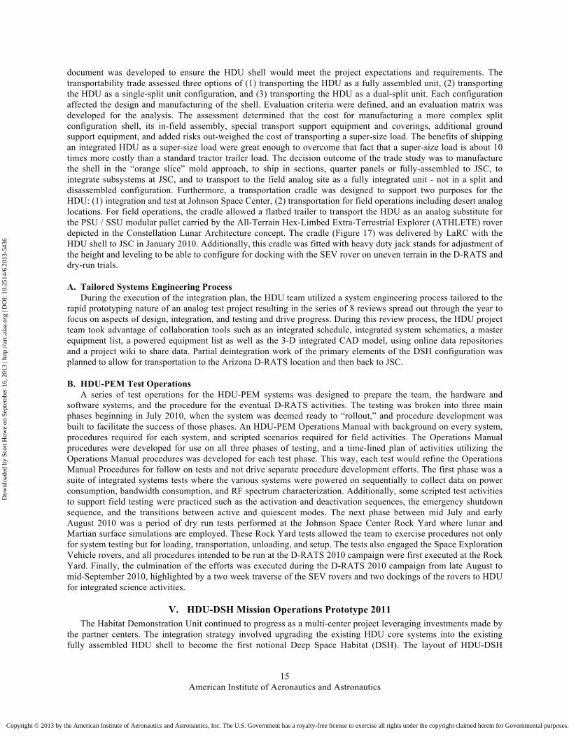
Finally, the culmination of all the test and integration activities was the utilization of the HDU-DSH in Arizona to support the D-RATS 2011 field test operations (Abercromby, Chappell, Gernhardt 2012) from late August through mid-September of 2011 (Figure 1). The focus of these tests were science activities for an exploration mission using a Deep Space Habitat and a Space Exploration Vehicle at a simulated asteroid. One of the more unusual experiences of that test campaign was the tornado a few miles from our test site during our public outreach day, and the HDU was probably the safest structure in the area. Figure 21 shows the HDU-DSH internal configuration for 2011 D-RATS, with the lower lab deck (Figure 21, left) and upper X-Loft dome interior (Figure 21, right).
Figure 21: HDU-DSH 2011 interior configuration, lab (left), X-Loft (right) (photos by James W. Young)
VI. HDU-DSH Mission Operations Prototype 2012
The 2012 DSH focused on the six month “return mode” of the near-Earth asteroid mission—having performed the “sample mode” mission testing in the previous year. Thus the basic configuration of the notional Deep Space Habitat didn’t change much for the third yearly campaign in 2012 of the Habitat Demonstration Unit team. The team focused on maturing and improving the subsystems, work stations, and technology demonstrations. The habitat X-Loft living quarters were modified based on feedback from the D-RATS 2011 campaign (Figure 22). In 2012, the HDU Project became an official agency project under the Advanced Exploration Systems (AES) program of NASA’s Human Exploration Operations Mission Directorate (HEOMD). The project became known as the AES Habitat Systems and then the AES Deep Space Habitat Project. The main purpose of the AES-DSH project continued to be advancing concepts and maturing and testing new technologies and improved subsystems to advance capabilities required for long duration space habitation.
Dow
nloa
ded
by S
cott
How
e on
Sep
tem
ber
16, 2
013
| http
://ar
c.ai
aa.o
rg |
DO
I: 1
0.25
14/6
.201
3-54
36
Copyright © 2013 by the American Institute of Aeronautics and Astronautics, Inc. The U.S. Government has a royalty-free license to exercise all rights under the copyright claimed herein for Governmental purposes. All other rights are reserved by the copyright owner.

American Institute of Aeronautics and Astronautics
19
Figure 22: AES-DSH redesigned X-Loft configuration, CAD model (left), roomy crew quarters (middle), galley (right)
Figure 23: crew at work during the 2012 Mission Operations Test at JSC (left), airlock configuration (right) A. X-Hab Academic Innovation Challenge 2012
One significant change was that the X-Hab Academic Innovation Challenge evolved away from being a head-to-head competition. Rather than have teams compete to do the same thing as was done with having three teams build a version of the habitat loft in the first challenge, the team decided to offer a suite of projects and selected a group of winning proposals to all contribute unique hardware or software projects to the Deep Space Habitat body of work. The HDU management team made this change in order to get more value out of the funding towards different aspects of Deep Space Habitats. University teams were brought on board as Principal Investigators (PI) of their respective products, allowing the students to be peers in the critical path with the NASA experts. Howe reports that student teams take greater ownership of the product, and are involved in the overall NASA vision to a greater degree (Howe 2012). The X-Hab Academic Innovation Challenge followed this same pattern in subsequent years, resulting in many superior products, satisfied technology teams, and some internships for students. Some of the X-Hab products are highlighted later. B. Mission Operations Test at JSC
For this third campaign of the HDU, the mission scenario focused on the “cruise” stage of an exploration mission to an asteroid. Because of that focus, it was not deemed necessary to travel to the desert location in Arizona since the geologic benefits of that region were not applicable for the deep space phase. Therefore, the word “desert” was
Dow
nloa
ded
by S
cott
How
e on
Sep
tem
ber
16, 2
013
| http
://ar
c.ai
aa.o
rg |
DO
I: 1
0.25
14/6
.201
3-54
36
Copyright © 2013 by the American Institute of Aeronautics and Astronautics, Inc. The U.S. Government has a royalty-free license to exercise all rights under the copyright claimed herein for Governmental purposes. All other rights are reserved by the copyright owner.

American Institute of Aeronautics and Astronautics
20
removed from the test campaign and simply called the Mission Operations Test (MOT) The MOT was held at Johnson Space Center allowing our team to save travel money which proved valuable in a budget constrained environment (Figure 23).
VII. HDU Technologies and Subsystems
HDU subsystems evolved over the three years, using feedback from the D-RATS and Mission Operations Tests to improve the products and integrate more efficiency. A detailed summary of many of the HDU technologies and subsystems follows.
A. System Integration (M Amoroso, C Chapman) The goal of the integration subsystem was to assemble all of the parts of the Habitat. This was an ever evolving
task as components and requirements were frequently changing. The integration included working with all of the other subsystems to become familiar with all of their constraints, which included electrical, environmental, structural, and volume requirements. The system integration group acted as the liaison between the groups to make sure that everything could be accommodated and was installed in a safe and effective configuration.
The integration team dealt with all ends of the size spectrum for the components. They were responsible for assisting in the building of the structure as a whole, building the Hygiene Unit (Figure 19, Figure 42), Airlock (Figure 23, right), and the Crew Quarters (Figure 40). These tasks included full design, assisted design and building/assembly. Each unit provided us with different challenges.
Figure 24: Personnel lift from top deck (left), winch mechanism (right). Bright purple lighting comes from the red / blue LED lighting from the Plant Growth Atrium encircling the lift at the interface between levels
Core module was the first module build for the Deep Space Habitat. This module was the main processing center for all of the data and therefore contained most of the electrical components. Due to the volumetric constraints about the floor the team had to be creative and find ways to package as many components under the floor as possible. Some of the major components stored under the floor were all six of the PDU’s (Figure 35), all of the avionics (Figure 28, Figure 29), communications (Figure 36), and instrumentation equipment (Figure 37) as well as several system control components. The space under the floor was quite limited and caused the team to be resourceful for component placement and using every open space. The biggest challenge was being able to understand the path forward and plan the space and capabilities to be able to support that without a significant reconfiguration. When an access panel in the floor is removed it reveals what appears to be a different look with extensive lengths of wiring and dozens of electrical components. Some other difficult challenges included trying to find a home for components as the module filled up. One example of this is the Plant Atrium. In order to be able to host all seven trays together in the module they needed to be nested into another system. This was accomplished by placing the trays and lights in a small void that was left between the elevator and the overhead stowage system (Figure 47).
Dow
nloa
ded
by S
cott
How
e on
Sep
tem
ber
16, 2
013
| http
://ar
c.ai
aa.o
rg |
DO
I: 1
0.25
14/6
.201
3-54
36
Copyright © 2013 by the American Institute of Aeronautics and Astronautics, Inc. The U.S. Government has a royalty-free license to exercise all rights under the copyright claimed herein for Governmental purposes. All other rights are reserved by the copyright owner.
American Institute of Aeronautics and Astronautics
21
The integration group faced a significant challenge with regards to the translation from the core module to the loft area. In a zero gravity environment it would not be a problem but for the Earth based testing the small transition area meant that people, equipment and supplies would need to be transported in a safe and effective manner. For this the team researched different devices and mechanisms to accomplish this. After several meetings and ideas being proposed a man lift was determined to be the best option for the habitat to transport people and cargo between levels. After being told that it could not be done from several vendors, Christopher Chapman (JSC) stepped forward to design and certify a compact human rated man lift. The lift could be operated from each floor as well as the platform to make moving equipment easy. As an added feature the lift also came equipped with a built in ladder for the times that the crew did not want to take the ride (Figure 24).
The Hygiene module was attached to the Core Module, and accessed by a door in the “A” segment. The module included the facilities to perform common bathroom functions. It contained a water system which included an external reservoir, pump, and a small water heater located below the floor of the hygiene module. There was also a waste water collection tank below the hygiene module floor to store the used water that was used in the sink and the shower. The sink included separate faucets for ambient and hot water. In an effort to regulate the shower water usage, the shower did not include running water, but employed a two-liter bag that was to be filled at the sink and attached to the ceiling of the shower. The crewmember would manually dispense the water as needed. The shower included cloth walls and a floor drain, and the used water was routed to the used water collection tank. The purpose of the Mission Operations test was not to prove or disprove the toilet, so a camper toilet was used and was emptied twice per day by non-crewmembers. It was accessed through an external hatch, so the non-crewmembers would not have to enter the HDU to perform this function. This also eliminated the potential risk of spilling the waste on the floor and it seeping into the electronics under the floor. The hygiene module also included three trash receptacles for dry and wet trash. The wet trash was emptied daily, while the dry trash was only emptied when full. The hygiene module also had a lot of additional storage space. The crewmember’s hygiene supplies were stored there, along with their towel supply. But there was also storage for other non-essential things. As a part of the Logistics-to-living activities, partition walls were made from CTB bags and used as separation walls in the hygiene module (Figure 42, left).
The loft started out as a X-hab project and was developed and improved from one year to the next. In the second year a complete interior remodel was completed. This included an entirely new structure to create four individual crew quarters, with storage and a lower section which contained the exercise, galley and meeting area (Figure 22). The area also provided several surfaces to project various environments onto the walls. Taking some of the crew recommendations the team installed foam sound batting as well as a new inner wall which had a thermal insulator sewn into the fabric.
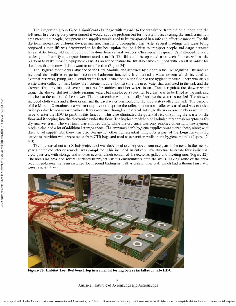
Figure 25: Habitat Test Bed bench top incremental testing before installation into HDU
Dow
nloa
ded
by S
cott
How
e on
Sep
tem
ber
16, 2
013
| http
://ar
c.ai
aa.o
rg |
DO
I: 1
0.25
14/6
.201
3-54
36
Copyright © 2013 by the American Institute of Aeronautics and Astronautics, Inc. The U.S. Government has a royalty-free license to exercise all rights under the copyright claimed herein for Governmental purposes. All other rights are reserved by the copyright owner.

American Institute of Aeronautics and Astronautics
22
B. Habitat Test Bed (D Carrejo) The Habitat Testbed served as the proof of concept and early integration platform for HDU subsystems and
technologies. HDU subsystems would undergo testing on a bench top environment in the testbed before being physically integrated into the HDU module (Figure 25). Because the testbed was also continuously connected to the HDU, subsystems could be incrementally integrated on either the testbed side or HDU side while remaining part of the overall vehicle configuration. This allowed continuous operation of the entire HDU configuration while performing subsystem integration and testing. Once the HDU was completely outfitted, the Habitat Testbed served as a real-time monitoring and troubleshooting facility during both integration tests and mission operations tests. A mobile version of the testbed was transported to the field for D-RATS to provide insight and support during HDU operations (Figure 26).
Figure 26: Habitat Test Bed used as a monitoring station for integrated subsystems
C. Structures (R Smith) As mentioned previously, the core HDU structure was designed and fabricated at Langley Research Center
(LaRC), based off of the Constellation Lunar Outpost module design. Beyond the original module, a number of additional secondary structural components were added to the unit. It should be noted that pressure rated, primary structure did not fit within the available resource pool at the time, and hence developments were confined to secondary structures. As such, a structural construction method was investigated which involved composite honeycomb panel concepts, and which also included novel additive manufactured components for mechanical fasteners (a provisional patent has currently been issued). Shown in Figure 27 are some representative components from this phase of the activity (Smith, Langford 2012).
Dow
nloa
ded
by S
cott
How
e on
Sep
tem
ber
16, 2
013
| http
://ar
c.ai
aa.o
rg |
DO
I: 1
0.25
14/6
.201
3-54
36
Copyright © 2013 by the American Institute of Aeronautics and Astronautics, Inc. The U.S. Government has a royalty-free license to exercise all rights under the copyright claimed herein for Governmental purposes. All other rights are reserved by the copyright owner.

American Institute of Aeronautics and Astronautics
23
Figure 27: Secondary structural elements added to HDU: evolved flooring section (upper left), floor support beam for section (upper right), upper loft lift cover (lower left), upper loft lift cover backside (lower right) It should also be noted that Figure 23 also shows the installed composite honeycomb panel and beam section as well as 2012 year’s “Smart Rail” integrated sub-system fabrication prototype demonstrator (it is the circular handrail section directly behind the blue hanging curtain in the figure).
D. Avionics (A Rawlin) The HDU Avionics System was physically located under the floor in sections D and E of the HDU (see Figure
14 for reference). This location was mandated by the HDU management as a requirement due to the limited space of the HDU inner volume and the expected manned operations that took place there.
The HDU Avionics System was divided into two physical racks each custom configured and designed. The racks were designed to be sealed against dust and dirt intrusion to protect the integrity of the internal electronics. The two racks were designated Red and Blue so that they could be distinguished from one another. Each rack was networked to each other and to external components utilizing an IEEE 802.3 Ethernet protocol via a layer 2/3 network switch. Each switch contained 24 ports each meeting the IEEE 802.3af-2003 specification which allows Power over Ethernet at a maximum of 15.4 W of power per port. Each port also met the IEEE 802.3ab specification and is capable of auto negotiation of 10/100/1000 Mbps. This Ethernet Backbone created the core data network for the HDU. For the Communications, Command and Data Handling the HDU utilized two central computers one operating with an i7-860 quad core processor, running eight threads total, i.e. two threads per core. The other central computer is a single board computer, utilizing a single core Power PC 750FL processor. The SBC is in a 3U compact PCI configuration, operating on a real time clock utilizing VxWorks as the operating system. Specifics of the two central computer processors will be given in a later section of this paper. The rest of the system was composed of a Data Server operating on an Intel based E6400 Core 2 Duo processor utilizing a Linux operating system. These three computers with a rack power distribution unit was the composition of the Blue rack (Figure 28). The Red rack consisted of an identical computer as the Blue rack Data Server but utilized Windows XP as the
“US” quarter for scale Upper Flange to flooring insert Lower Flange bracket insert
Handles Rib Stiffeners Handle Inserts
Dow
nloa
ded
by S
cott
How
e on
Sep
tem
ber
16, 2
013
| http
://ar
c.ai
aa.o
rg |
DO
I: 1
0.25
14/6
.201
3-54
36
Copyright © 2013 by the American Institute of Aeronautics and Astronautics, Inc. The U.S. Government has a royalty-free license to exercise all rights under the copyright claimed herein for Governmental purposes. All other rights are reserved by the copyright owner.

American Institute of Aeronautics and Astronautics
24
operating system; this computer was used as the Wireless Networks Controller. Further the Red rack contained a Network Video Recorder and a 1 U hybrid chassis with electronic hardware for rack internal data acquisition (DAQ), a radio transceiver for communicating with wireless mesh sensors, two radio transceivers for communicating with cordless audio equipment, and a Network Address Translation switch. Further the Red Rack also contained a power distribution unit for monitoring and controlling the rack internal power. See Figure 29 for a schematic of the Red rack internal configuration.
Figure 28: HDU Avionics Blue Rack, schematic (left) and photo (right)
Figure 29: HDU Avionics Red Rack schematic (left) and photo (right)
E. Software (D Lawler, L Wang) The software team achieved a near-flight-like software environment for the HDU, culminating in the advanced
crew displays used in the 2012 Mission Operations Test (MOT). The graphical interface consisted of point-and-click buttons and displays for all the HDU subsystems to allow crew and ground support to monitor and control every aspect of the habitat. The main panel is shown in Figure 30, left. Clicking on a “power” icon will bring the graphical display to the power system page (Figure 30, right) and allow the user to monitor and control power levels for various subsystems. Figure 31 shows the various live video streams, allowing a user to click on a particular camera to enlarge it and, depending on the function of the camera, aim or zoom the camera view.
Dow
nloa
ded
by S
cott
How
e on
Sep
tem
ber
16, 2
013
| http
://ar
c.ai
aa.o
rg |
DO
I: 1
0.25
14/6
.201
3-54
36
Copyright © 2013 by the American Institute of Aeronautics and Astronautics, Inc. The U.S. Government has a royalty-free license to exercise all rights under the copyright claimed herein for Governmental purposes. All other rights are reserved by the copyright owner.

American Institute of Aeronautics and Astronautics
25
Figure 30: Crew display main panel (left), and power panel (right)
Figure 31: Crew display video panel
The software team also created a “iHab Digital Double” using the CAD model of the HDU. In the Digital Double, a crewmember could use an Apple iPad to view a three-dimensional partially transparent view of the CAD model and click on highlighted subsystems to monitor or control them (Figure 33). Digital double technology has been tested by members of the HDU team using VRML models (Howe 1997), but the HDU Digital Double functionality shows tremendous potential as a powerful graphical interface for monitoring and control, that could not have been achieved using the earlier technologies (Figure 32).
Dow
nloa
ded
by S
cott
How
e on
Sep
tem
ber
16, 2
013
| http
://ar
c.ai
aa.o
rg |
DO
I: 1
0.25
14/6
.201
3-54
36
Copyright © 2013 by the American Institute of Aeronautics and Astronautics, Inc. The U.S. Government has a royalty-free license to exercise all rights under the copyright claimed herein for Governmental purposes. All other rights are reserved by the copyright owner.

American Institute of Aeronautics and Astronautics
26
Figure 32: iHab Digital Double architecture concept
Figure 33: HDU Digital Double model: a point-and-click three dimensional graphical user interface
HDU Simulation
SysML Models
i-Hab 3DV
i-Hab D&C
ICE Interface DDS Data Interface
HDU Core Software
i-Hab PD
ETDD/ ASA ISHM
Discrete Control
ACWS
Dow
nloa
ded
by S
cott
How
e on
Sep
tem
ber
16, 2
013
| http
://ar
c.ai
aa.o
rg |
DO
I: 1
0.25
14/6
.201
3-54
36
Copyright © 2013 by the American Institute of Aeronautics and Astronautics, Inc. The U.S. Government has a royalty-free license to exercise all rights under the copyright claimed herein for Governmental purposes. All other rights are reserved by the copyright owner.
American Institute of Aeronautics and Astronautics
27
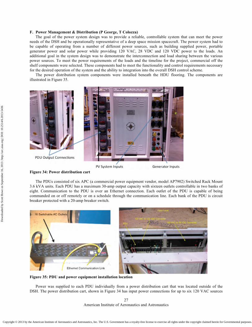
F. Power Management & Distribution (P George, T Colozza) The goal of the power system design was to provide a reliable, controllable system that can meet the power
needs of the DSH and be operationally representative of a deep space mission spacecraft. The power system had to be capable of operating from a number of different power sources, such as building supplied power, portable generator power and solar power while providing 120 VAC, 28 VDC and 120 VDC power to the loads. An additional goal in the system design was to demonstrate the interconnection and load sharing between the various power sources. To meet the power requirements of the loads and the timeline for the project, commercial off the shelf components were selected. These components had to meet the functionality and control requirements necessary for the desired operation of the system and the ability to integration into the overall DSH control scheme.
The power distribution system components were installed beneath the HDU flooring. The components are illustrated in Figure 35.
Figure 34: Power distribution cart
The PDUs consisted of six APC (a commercial power equipment vendor, model AP7902) Switched Rack Mount 3.6 kVA units. Each PDU has a maximum 30-amp output capacity with sixteen outlets controllable in two banks of eight. Communication to the PDU is over an Ethernet connection. Each outlet of the PDU is capable of being commanded on or off remotely or on a schedule through the communication line. Each bank of the PDU is circuit breaker protected with a 20-amp breaker switch.
Figure 35: PDU and power equipment installation location
Power was supplied to each PDU individually from a power distribution cart that was located outside of the DSH. The power distribution cart, shown in Figure 34 has input power connections for up to six 120 VAC sources
Dow
nloa
ded
by S
cott
How
e on
Sep
tem
ber
16, 2
013
| http
://ar
c.ai
aa.o
rg |
DO
I: 1
0.25
14/6
.201
3-54
36
Copyright © 2013 by the American Institute of Aeronautics and Astronautics, Inc. The U.S. Government has a royalty-free license to exercise all rights under the copyright claimed herein for Governmental purposes. All other rights are reserved by the copyright owner.

American Institute of Aeronautics and Astronautics
28
and one 3-phase 480 VAC source. There are two 480 VAC 3-phase power outputs and six individual 120 VAC outputs for connecting to the PDUs. The cart converts the 3-phase 480 VAC input source to a single phase 120 VAC output for powering the PDUs. The power distribution cart can provide up to 30 amps at 120 VAC to each PDU through an outlet on the outer wall of the DSH. The power conditioning cart is fully instrumented and provides current data on all inputs and outputs connected to it.
G. Thermal (J Cornwell) The HDU had a dedicated forced air unit air conditioner on a dedicated equipment cart, with suppy and return air
ducts to each module. Air conditioning supply air entered a plenum under the floor of the HDU module, bathing the volume in cool air for the cooling of avionics and other hardware located under the floor. From the under floor plenum, supply ducts provided cool air to the hygiene module, dust mitigation module, and x-loft dome. Though the HDU thermal system consisted of an earth-based building cooling system out of necessity due to the non-pressurized nature of an earth analog, space thermal systems were designed on paper for the module that could be further refined, designed, and installed in a higher-fidelity prototype.
H. Communications (M Miller) The D-RATS analog field mission tested various mission scenarios for exploring a destination such as the moon
or, most recently, an asteroid. These field missions tested some of the operational concepts developed by NASA HQ-led exploration architecture studies. The need for common avionics between the in-space elements (MMSEV, DSH) has surfaced as a viable and economical alternative to double and triple redundant avionics. Another prime advantage to this approach is a shared development cost between the projects.
During the 2011 field test, the communications system was the first and only to have an identical Line Replaceable Unit (LRU) in the MMSEV and DSH. This followed the common avionics approach and would accommodate the LRUs being swapped between the MMSEV and DSH.
Figure 36: Line Replaceable Unit (LRU) under floor of HDU (left), LRU mounting fixture (right)
There are two communication LRUs in the MMSEV and one in the DSH. Careful consideration was made to engineer all of the common components in the same enclosure. The interchangeable LRU consisted of the networking and voice communication components. Accommodations were made to account for the different bus voltages between the two vehicles. A custom fixture (Figure 36, right) was designed and fabricated to mount the communication LRU under the floor of the DSH (Figure 36, left) while allowing for easy removal for repairs.
The industrial-rated network switch provided the wired communication backbone for all equipment, including other network switches for various avionics systems. Depending on the location of the DSH, it was connected to the site test infrastructure via hardwire (at JSC), point-to-point backhaul wireless (in the field several kilometers away from base camp), or meshing wireless (when located near base camp).
Dow
nloa
ded
by S
cott
How
e on
Sep
tem
ber
16, 2
013
| http
://ar
c.ai
aa.o
rg |
DO
I: 1
0.25
14/6
.201
3-54
36
Copyright © 2013 by the American Institute of Aeronautics and Astronautics, Inc. The U.S. Government has a royalty-free license to exercise all rights under the copyright claimed herein for Governmental purposes. All other rights are reserved by the copyright owner.

American Institute of Aeronautics and Astronautics
29
The primary method of voice communication for the crew was a PC-based application running on each of the computers in the DSH. The computers were outfitted with headsets to minimize distractions in the limited space. Mission control in the field used the same software, which provided full-duplex communication on all channels simultaneously. The application tied into a custom Asterisk server that joined crew members on EVA, the test support team on hand-held radios, the remote science backroom team at JSC, both MMSEV rovers, and remotely-located phone lines on one hybrid voice communication system.
I. Wireless Instrumentation (K Rojdev) The objectives of the instrumentation system were to create a standards-based, modular instrumentation system
while simultaneously meeting the monitoring needs of the HDU subsystems. In 2010, the instrumentation system had to be built from the ground up. So, requirements for the instrumentation system were gathered from the subsystem leads of the HDU, and Commercial-Off-The-Shelf (COTS) hardware was investigated for use. In addition, the instrumentation system leveraged knowledge and lessons learned from previous instrumentation systems to implement a “standards-based” approach to a wireless system with flexibility for reconfiguration, i.e. modular (Rojdev, Kennedy, Williams, Yim, Hong, Studor, Delaune, Wagner 2010). To accomplish this, a wireless mesh network was implemented to eliminate the frequency interference that could be experienced from multiple wireless COTS devices. A device called the Wireless Sensor Node (WSN) was created in-house that would accept data from ten various sensors, packet the data, and send the data wirelessly over the mesh network to the command and data handling system. This allowed the data to be collated by one type of software and displayed on a crew display, rather than having multiple types of COTS software that were incompatible with siphoning data to a crew display via a simple method.
While a fully wireless instrumentation system was desired, there were still concerns regarding reliability of such a system for safety critical components. Thus, all safety critical sensors were hard-wired for reliability reasons.
The subsystems that required instrumentation are the following: Structures, Thermal Control, Environmental Control and Life Support, and Vegetable Production. The types of sensors selected to support these subsystems are the following: accelerometers, temperature sensors, humidity sensors, differential pressure sensors, airflow sensors, photoresistors, carbon dioxide monitors, smoke/CO alarms, and oxygen monitors. For the 2010 PEM configuration, there were approximately 59 sensors and 8 WSNs (Figure 37).
Figure 37: Instrumentation integration into the 2010 HDU-PEM
Dow
nloa
ded
by S
cott
How
e on
Sep
tem
ber
16, 2
013
| http
://ar
c.ai
aa.o
rg |
DO
I: 1
0.25
14/6
.201
3-54
36
Copyright © 2013 by the American Institute of Aeronautics and Astronautics, Inc. The U.S. Government has a royalty-free license to exercise all rights under the copyright claimed herein for Governmental purposes. All other rights are reserved by the copyright owner.

American Institute of Aeronautics and Astronautics
30
In 2011, the HDU expanded to include a loft, a hygiene module, and an expanded Vegetable growth system
(Rojdev, Kennedy, Yim, Williams, Wagner, Hafermalz 2011). So, the instrumentation system needed to expand as well to meet the monitoring needs of the new design. Thus, the focus for 2011 was this expansion with upgrades to the previous system from lessons learned in the 2010 D-RaTS testing. The additional instrumentation added was the following: Smoke/CO alarms, carbon dioxide monitors, oxygen monitors, air flow sensors, temperature sensors, photoresistors, wind sensor (for the loft), and humidity sensors. The total sensor count at the end of 2011 was 110 sensors and 13 WSNs.
In addition, the instrumentation system had the capability to now support technology developments interested in interfacing with the HDU. These technology developments are the following: a Radio Frequency Identification System (RFID) for the Geology laboratory to track inventory of rock samples and their respective data, a RFID system for the hygiene module to keep track of inventory and crew usage of consumables, and a Flat Surface damage detection system (FSDDS) developed by KSC to monitor damage to the spacecraft in the event of a micrometeoroid hit. Both RFID systems were developed at JSC and there were approximately 120 RFID tags in use for the testing at D-RATS.
In 2012, the HDU did not change much. So, the instrumentation system focused primarily on technology development through collaborations and partnerships. The technology developments from 2011 remained with the HDU team and continued to upgrade their hardware. The RFID system from the hygiene module was moved into the medical operations workstation to investigate inventory management of medical supplies. The RFID system in the geology lab remained there, but with further integration into the software to make book keeping of data more automatic. The FSDDS single panel was integrated with the HDU software and crew display, and a dual panel stand-alone system was also investigated.
In 2013, the instrumentation was removed from the HDU in preparation for its transition to HERA. The instrumentation has been relocated to a bench top testbed, where it continues to be used for deep space habitat avionics and software testing, such as integrated system health monitoring.
J. Environmental Control and Life Support (R Barido) The HDU prototype was a non-pressurized, medium fidelity analog and therefore did not require flight-like
ECLS systems. However air ventilation, fire suppression, environmental monitoring, water processing, and other analog studies reflected some aspects of how an ECLS system would integrate with other habitat functions.
Figure 38: HDU Galley (left) and wardroom table (right)
Dow
nloa
ded
by S
cott
How
e on
Sep
tem
ber
16, 2
013
| http
://ar
c.ai
aa.o
rg |
DO
I: 1
0.25
14/6
.201
3-54
36
Copyright © 2013 by the American Institute of Aeronautics and Astronautics, Inc. The U.S. Government has a royalty-free license to exercise all rights under the copyright claimed herein for Governmental purposes. All other rights are reserved by the copyright owner.
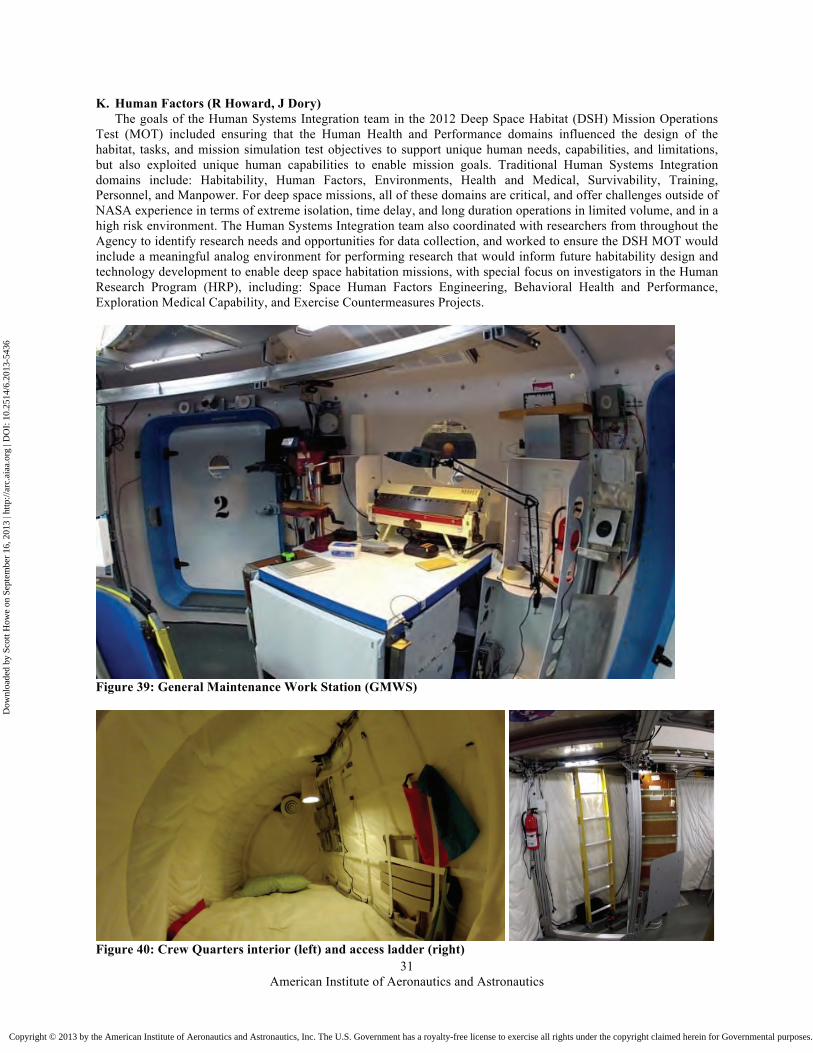
American Institute of Aeronautics and Astronautics
31
K. Human Factors (R Howard, J Dory) The goals of the Human Systems Integration team in the 2012 Deep Space Habitat (DSH) Mission Operations
Test (MOT) included ensuring that the Human Health and Performance domains influenced the design of the habitat, tasks, and mission simulation test objectives to support unique human needs, capabilities, and limitations, but also exploited unique human capabilities to enable mission goals. Traditional Human Systems Integration domains include: Habitability, Human Factors, Environments, Health and Medical, Survivability, Training, Personnel, and Manpower. For deep space missions, all of these domains are critical, and offer challenges outside of NASA experience in terms of extreme isolation, time delay, and long duration operations in limited volume, and in a high risk environment. The Human Systems Integration team also coordinated with researchers from throughout the Agency to identify research needs and opportunities for data collection, and worked to ensure the DSH MOT would include a meaningful analog environment for performing research that would inform future habitability design and technology development to enable deep space habitation missions, with special focus on investigators in the Human Research Program (HRP), including: Space Human Factors Engineering, Behavioral Health and Performance, Exploration Medical Capability, and Exercise Countermeasures Projects.
Figure 39: General Maintenance Work Station (GMWS)
Figure 40: Crew Quarters interior (left) and access ladder (right)
Dow
nloa
ded
by S
cott
How
e on
Sep
tem
ber
16, 2
013
| http
://ar
c.ai
aa.o
rg |
DO
I: 1
0.25
14/6
.201
3-54
36
Copyright © 2013 by the American Institute of Aeronautics and Astronautics, Inc. The U.S. Government has a royalty-free license to exercise all rights under the copyright claimed herein for Governmental purposes. All other rights are reserved by the copyright owner.

American Institute of Aeronautics and Astronautics
32
Figure 41: Telerobotics Work Station (left), and eye tracking of workstation (right)
The DSH MOT offered the opportunity for 24-hour, ten-day simulation test environment, in which crew performed representative mission tasks related to the return leg of a 400-day mission to a Near Earth Asteroid, while operating within realistic volume and power constraints, and relatively isolated from the outside world with the exception of a Mission Control Center who communicated via 50 second and 5 second time delay, representing two different points in the mission, and two different distances from Earth. As such, the MOT offered the opportunity to evaluate a number of unique interfaces, technologies, and operations concepts in an physical and operational test environment that simulated a real deep space mission, offering opportunities for learning that would not be available in either a part-task simulators, or in a shorter test. In particular, the affects of multiple competing tasks operating concurrently in small volume, and the crew’s perception of habitability after a multi-day, isolated operation with a high workload were of interest.
Among other things, the Human Systems Integration team provided a galley (coordinated with Crew Accommodations, Figure 38 left), wardroom table (Figure 38, right), Crew Quarters (with Crew Accommodations, Figure 40), Medops Workstation (Howard 2012b), and General Mainenance Workstation (Figure 39). The Human Systems Integration team also performed analysis such as eye tracking on the Telerobotics Workstation (Figure 41).
Figure 42: Hygiene Module interior (left), sink (middle), and trash bins (right)
L. Crew Accommodations & Hygiene (S Baccus, M Borrego) The Crew Accommodations subsystem includes many different habitation systems that provide basic life support
functions such as crew rest, food preparation, general hygiene and waste/trash collection and management. As well crew accommodations covers such topics as general housekeeping, stowage and logistics, and crew items and interfaces.
Dow
nloa
ded
by S
cott
How
e on
Sep
tem
ber
16, 2
013
| http
://ar
c.ai
aa.o
rg |
DO
I: 1
0.25
14/6
.201
3-54
36
Copyright © 2013 by the American Institute of Aeronautics and Astronautics, Inc. The U.S. Government has a royalty-free license to exercise all rights under the copyright claimed herein for Governmental purposes. All other rights are reserved by the copyright owner.
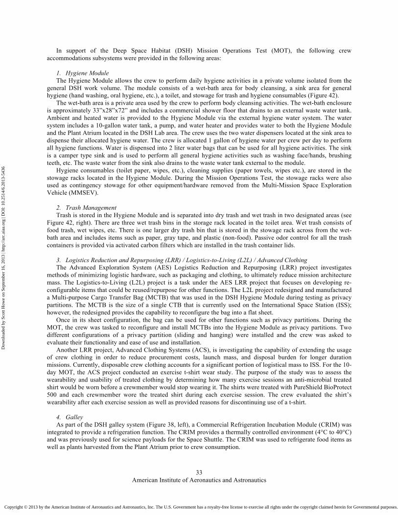
American Institute of Aeronautics and Astronautics
33
In support of the Deep Space Habitat (DSH) Mission Operations Test (MOT), the following crew accommodations subsystems were provided in the following areas:
1. Hygiene Module The Hygiene Module allows the crew to perform daily hygiene activities in a private volume isolated from the
general DSH work volume. The module consists of a wet-bath area for body cleansing, a sink area for general hygiene (hand washing, oral hygiene, etc.), a toilet, and stowage for trash and hygiene consumables (Figure 42).
The wet-bath area is a private area used by the crew to perform body cleansing activities. The wet-bath enclosure is approximately 33”x28”x72” and includes a commercial shower floor that drains to an external waste water tank. Ambient and heated water is provided to the Hygiene Module via the external hygiene water system. The water system includes a 10-gallon water tank, a pump, and water heater and provides water to both the Hygiene Module and the Plant Atrium located in the DSH Lab area. The crew uses the two water dispensers located at the sink area to dispense their allocated hygiene water. The crew is allocated 1 gallon of hygiene water per crew per day to perform all hygiene functions. Water is dispensed into 2 liter water bags that can be used for all hygiene activities. The sink is a camper type sink and is used to perform all general hygiene activities such as washing face/hands, brushing teeth, etc. The waste water from the sink also drains to the waste water tank external to the module.
Hygiene consumables (toilet paper, wipes, etc.), cleaning supplies (paper towels, wipes etc.), are stored in the stowage racks located in the Hygiene Module. During the Mission Operations Test, the stowage racks were also used as contingency stowage for other equipment/hardware removed from the Multi-Mission Space Exploration Vehicle (MMSEV).
2. Trash Management Trash is stored in the Hygiene Module and is separated into dry trash and wet trash in two designated areas (see
Figure 42, right). There are three wet trash bins in the storage rack located in the toilet area. Wet trash consists of food trash, wet wipes, etc. There is one larger dry trash bin that is stored in the stowage rack across from the wet-bath area and includes items such as paper, gray tape, and plastic (non-food). Passive odor control for all the trash containers is provided via activated carbon filters which are installed in the trash container lids.
3. Logistics Reduction and Repurposing (LRR) / Logistics-to-Living (L2L) / Advanced Clothing The Advanced Exploration System (AES) Logistics Reduction and Repurposing (LRR) project investigates
methods of minimizing logistic hardware, such as packaging and clothing, to ultimately reduce mission architecture mass. The Logistics-to-Living (L2L) project is a task under the AES LRR project that focuses on developing re-configurable items that could be reused/repurpose for other functions. The L2L project redesigned and manufactured a Multi-purpose Cargo Transfer Bag (MCTB) that was used in the DSH Hygiene Module during testing as privacy partitions. The MCTB is the size of a single CTB that is currently used on the International Space Station (ISS); however, the redesigned provides the capability to reconfigure the bag into a flat sheet.
Once in its sheet configuration, the bag can be used for other functions such as privacy partitions. During the MOT, the crew was tasked to reconfigure and install MCTBs into the Hygiene Module as privacy partitions. Two different configurations of a privacy partition (sliding and hanging) were installed and the crew was asked to evaluate their functionality and ease of use and installation.
Another LRR project, Advanced Clothing Systems (ACS), is investigating the capability of extending the usage of crew clothing in order to reduce procurement costs, launch mass, and disposal burden for longer duration missions. Currently, disposable crew clothing accounts for a significant portion of logistical mass to ISS. For the 10-day MOT, the ACS project conducted an exercise t-shirt wear study. The purpose of the study was to assess the wearability and usability of treated clothing by determining how many exercise sessions an anti-microbial treated shirt would be worn before a crewmember would stop wearing it. The shirts were treated with PureShield BioProtect 500 and each crewmember wore the treated shirt during each exercise session. The crew evaluated the shirt’s wearability after each exercise session as well as provided reasons for discontinuing use of a t-shirt.
4. Galley As part of the DSH galley system (Figure 38, left), a Commercial Refrigeration Incubation Module (CRIM) was
integrated to provide a refrigeration function. The CRIM provides a thermally controlled environment (4°C to 40°C) and was previously used for science payloads for the Space Shuttle. The CRIM was used to refrigerate food items as well as plants harvested from the Plant Atrium prior to crew consumption.
Dow
nloa
ded
by S
cott
How
e on
Sep
tem
ber
16, 2
013
| http
://ar
c.ai
aa.o
rg |
DO
I: 1
0.25
14/6
.201
3-54
36
Copyright © 2013 by the American Institute of Aeronautics and Astronautics, Inc. The U.S. Government has a royalty-free license to exercise all rights under the copyright claimed herein for Governmental purposes. All other rights are reserved by the copyright owner.

American Institute of Aeronautics and Astronautics
34
5. Environmental Characterization For longer duration missions, it is important to understand the environmental characteristics of a habitable
volume and its effects on crew comfort and work productivity. Adequate lighting, airflow, and acoustic levels are vital in a habitat where a crewmember will live and work for month or maybe years at a time.
During the MOT, the crew measured the lighting, airflow and acoustic levels in their individuals crew quarters (CQs). The crew used hand-held meters to perform these tasks. The CQs are newly designed structures located in the DSH Loft (Figure 40).
Overhead axis camera – remote controllable locally and from ground crew Screen computers Microscope Cameras and other instruments through side ports Glove box with three sample pass through airlocks to the exterior Control box
Figure 43: Geoscience GeoLab Workstation glovebox
M. Geoscience GeoLab Workstation (C Evans, M Calaway) The GeoLab glovebox was, until November 2012, fully integrated into NASA’s Habitat Demonstration Unit.
The conceptual design for GeoLab came from several sources, including current research instruments used on the International Space Station (Microgravity Science Glovebox), existing Astromaterials Curation Laboratory hardware and clean room procedures, and mission scenarios developed for earlier programs. The basic configuration of GeoLab is described more fully in Evans, Calaway, Bell & Young (2012) and Evans, Bell, Calaway, Graff & Young (2011).
GeoLab allowed NASA scientists to test science operations related to contained sample examination during simulated exploration missions. The team demonstrated science operations that enhance the early scientific returns from future missions and ensure that the best samples are selected for Earth return. The facility was also designed to foster the development of instrument technology.
Since 2009, when the GeoLab design and construction started, the GeoLab team (a group of scientists from the Astromaterials Acquisition and Curation Office within the Astromaterials Research and Exploration Science Directorate at the Johnson Space Center) progressively developed and reconfigured the GeoLab hardware and software interfaces, and evolved test objectives. GeoLab tests addressed the following goals: 1) determine requirements and strategies for sample handling and prioritization for geological operations on other planetary surfaces; 2) assess the scientific contribution of selective in-situ sample characterization for mission planning, operations, and sample prioritization; 3) evaluate analytical instruments and tools for providing efficient and meaningful data in advance of sample return; 4) identify science operations that leverage human presence with robotic tools.
In the first year of tests (2010), GeoLab examined basic glovebox operations with one and two crewmembers, and science operations with a remote science team (Evans, Calaway, Bell, Graff 2010; Evans, Calway, Bell 2009). The glovebox configuration and basic instrumentation is described elsewhere (Evans, Calaway 2012; Calaway, Bell,
Dow
nloa
ded
by S
cott
How
e on
Sep
tem
ber
16, 2
013
| http
://ar
c.ai
aa.o
rg |
DO
I: 1
0.25
14/6
.201
3-54
36
Copyright © 2013 by the American Institute of Aeronautics and Astronautics, Inc. The U.S. Government has a royalty-free license to exercise all rights under the copyright claimed herein for Governmental purposes. All other rights are reserved by the copyright owner.

American Institute of Aeronautics and Astronautics
35
Evans 2011; Calaway, Evans, Bell, Graff 2011b). It was equipped with video cameras to document operations, a stereomicroscope with a video camera to examine samples microscopically and capture screen views, a balance, and a handheld X-ray Fluoresence (XRF) instrument for geochemical analyses (Young, Hodges, Evans, Deans, Bualat, Heggy, Fong, Helper Hurtado 2010; Young, Evans, Hodges 2011; Young, Evans, Hodges 2012). The 2010 tests examined the efficacy of basic sample characterization (descriptions, microscopic imagery, XRF analyses) and feed-back to the science team (Evans, Bell, Calaway 2010; Calaway, Evans, Bell 2010). In year 2 (2011), the GeoLab team tested enhanced software and interfaces for the crew and science team, including web–based and mobile device displays (Evans, Bell, Calaway, Graff, Young 2011) and demonstrated lab configurability with new diagnostic instruments (Multispectral Microscopic Imager from the Jet Propulsion Lab and Arizona State University). In year 3 (2012), the GeoLab team installed and tested a robotic sample manipulator and evaluated robotic-human interfaces for science operations (Evans, Calaway, Bell 2012; Bell, Calaway, Evans, Li, Tong, Zhong, Dahiwala, Wang, Porter 2013).
Sample return missions have strict protocols to reduce potential contamination of samples, and sample handling in microgravity presents special challenges (Calaway, Evans, Bell, Graff 2011a). To begin to address these challenges in the GeoLab, scientists at the Johnson Space Center partnered with engineering students from the University of Bridgeport, in Bridgeport Connecticut. The students were awarded one of the 2012 National Space Grant Foundation Exploration Habitat (X-Hab) Academic Challenges to develop an engineering design for tools to handle geological samples for analysis in a microgravity glovebox environment (see http://www.nasa.gov/exploration/technology/deep_space_habitat/xhab/xhab-2012-progress.html). The Bridgeport X-Hab team designed and built a robotic arm system with a three-finger gripper that could manipulate geologic samples within the existing GeoLab glovebox (Figure 43). An innovation developed by the Bridgeport team was the large curvature of each finger, a design that reduced contact with the irregular surfaces of a rock sample, thus minimizing contamination risk while still allowing a significant capture force to be applied to uneven surfaces of a rock (Figure 59). Controllers were Ethernet enabled and connected to the DSH avionics network switches. A software interface for the controllers was designed by the DSH software team and was hosted on the GeoLab computer using touch screen technology above the glovebox.
Figure 44: Demonsration using Robonaut to collect and insert samples into the GeoLab sample airlocks
Dow
nloa
ded
by S
cott
How
e on
Sep
tem
ber
16, 2
013
| http
://ar
c.ai
aa.o
rg |
DO
I: 1
0.25
14/6
.201
3-54
36
Copyright © 2013 by the American Institute of Aeronautics and Astronautics, Inc. The U.S. Government has a royalty-free license to exercise all rights under the copyright claimed herein for Governmental purposes. All other rights are reserved by the copyright owner.

American Institute of Aeronautics and Astronautics
36
In addition to robotic sample handling within the glovebox, field demonstrations were conducted using NASA’s Robonaut, a remote-controlled humanoid robotic instrument (Figure 44). Using Robonaut, a crew member would not need to conduct an EVA, but could use goggles, gloves, and virtual immersion using the Robotnaut as a proxy to go out and pick up samples. The Robonaut would be capable of inserting the samples into one of the three pressurized sample airlocks that connect directly into the back of the GeoLab glovebox.
The tests of the robotic arm provided insight into technologies that will be required for higher readiness levels. The ultimate goal is to build a robotic system that could autonomously con-duct the preliminary examination of returned samples and downlink this data to Earth-based mission scientists. The team’s current goal for sample science in the context of planetary exploration is to have autonomous robotic systems, assisted by human crew members when required, that can 1) collect and stow samples in an archival manner, 2) conduct preliminary examination of samples. 3) downlink the data to mission scientists for sample return prioritization, and 4) maintain rigorous curation protocols that preserve the scientific integrity of the samples.
Over 3 years that GeoLab was integrated into the DSH, GeoLab participated in 19 days of simulated mission testing in full analog settings, and monitored operations with 18 different test subjects (Evans, Bell, Calaway 2013). The GeoLab team also conducted stand-alone tests with nearly 20 other operators. While complete compilation and assessment of test results is still underway, the GeoLab team can confidently report the following:
1) The GeoLab design supports autonomous crew operations of the basic glovebox functions. The trained crew enhances science returns by providing spontaneous observations; this is especially important when time delays preclude real-time science team involvement.
2) Good sample imagery is key for preliminary characterization. Imagery collected at a range of scales forms the basis for additional characterization. The earliest tests indicated that basic microscopy provided invaluable data for rapid assessment of samples.
3) Robotic assists for sample handling are critical in microgravity. Robotics aid crew and enable precision sample handling for data collection. The 2012 tests validated the quantity and quality of microscopy that could be achieved with a robotic sample holder. The sample holder made possible one-person operations (crew efficiency), provided flexibility in sample positioning (see Fig. 3), enabled systematic sample positioning, allowing for mapping of the sample for future analyses. Finally, proper robotic sample handling can result in less sample handling, and therefore present less risk of damaging or compromising a sample.
4) A combination of imaging tools and robotic tools provides significant flexibility for designing facilities and operations related to sample characterization and sample handling. Progressive tests using robotic interfaces will help develop requirements, instruments and procedures for different exploration scenarios.
5) Preliminary sample characterization provides data that supports smart decisions during mis-sion operations. Data supports sample prioritization, enables a better understanding of the regional geology being explored, highlights details on samples, and is useful for future exploration plans. The types of data that were collected in the GeoLab during the analog tests allow for wide dissemination and broad participation by scientists and students on Earth.
N. Telerobotics & IVA Workstation (David Mittman) On medium- to long-duration human spaceflight missions, latency in communications from Earth could reduce
efficiency or hinder local operations, control, and monitoring of the various mission vehicles and other elements. Regardless of the degree of autonomy of any one particular element, a means of monitoring and controlling the elements in real time based on mission needs would increase efficiency and response times for their operation. Since human crews would be present locally, a local means for monitoring and controlling all the various mission elements is needed, particularly for robotic elements where response to interesting scientific features in the environment might need near-instantaneous manipulation and control.
One of the elements proposed for medium- and long-duration human spaceflight missions, the Deep Space Habitat (DSH), is intended to be used as a remote residence and working volume for human crews. The proposed solution for local monitoring and control would be to provide a workstation within the DSH where local crews can operate local vehicles and robotic elements with little to no latency.
The Telerobotics Workstation (TRWS) is a multi-display computer workstation mounted in a dedicated location within the DSH that can be adjusted for a variety of configurations as required (Figure 45, Figure 41 left). From an Intra-Vehicular Activity (IVA) location, the TRWS uses the Robot Application Programming Interface Delegate (RAPID) control environment (Torres, Allan, Hirsh, Wallick 2009) through the local network to remotely monitor and control vehicles and robotic assets located outside the pressurized volume in the immediate vicinity or at low-latency distances from the habitat (Figure 46). The multiple display area of the TRWS allows the crew to have
Dow
nloa
ded
by S
cott
How
e on
Sep
tem
ber
16, 2
013
| http
://ar
c.ai
aa.o
rg |
DO
I: 1
0.25
14/6
.201
3-54
36
Copyright © 2013 by the American Institute of Aeronautics and Astronautics, Inc. The U.S. Government has a royalty-free license to exercise all rights under the copyright claimed herein for Governmental purposes. All other rights are reserved by the copyright owner.

American Institute of Aeronautics and Astronautics
37
numerous windows open with live video feeds, control windows, and data browsers, as well as local monitoring and control of the DSH and associated systems.
Figure 45: Tele-Robotics Work Station (TRWS), previous generation (left), and 2012 configuration (right)
Figure 46: TRWS RAPID software for remote controlling rovers and other robotic assets
The novelty of the TRWS comes from the integration and configuration of various software and hardware elements within the context of the DSH environment. Controls, communications, power status, situational awareness information, and telemetry—though employing conventional and sometimes commercial off-the-shelf (COTS)
Dow
nloa
ded
by S
cott
How
e on
Sep
tem
ber
16, 2
013
| http
://ar
c.ai
aa.o
rg |
DO
I: 1
0.25
14/6
.201
3-54
36
Copyright © 2013 by the American Institute of Aeronautics and Astronautics, Inc. The U.S. Government has a royalty-free license to exercise all rights under the copyright claimed herein for Governmental purposes. All other rights are reserved by the copyright owner.
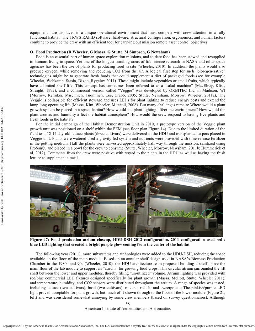
American Institute of Aeronautics and Astronautics
38
equipment—are displayed in a unique operational environment that must compete with crew attention in a fully functional habitat. The TRWS RAPID software, hardware, structural configuration, ergonomics, and human factors combine to provide the crew with an efficient tool for carrying out mission remote asset control objectives.
O. Food Production (R Wheeler, G Massa, G Stutte, M Simpson, G Newsham) Food is an essential part of human space exploration missions, and to date food has been stowed and resupplied
to humans living in space. Yet one of the longest standing areas of life science research in NASA and other space agencies has been the use of plants for producing food in situ (Wheeler, 2010). In addition, the plants would also produce oxygen, while removing and reducing CO2 from the air. A logical first step for such “bioregenerative” technologies might be to generate fresh foods that could supplement a diet of packaged foods (see for example Wheeler, Wehkamp, Stasia, Dixon, Rygalov 2011). These might include vegetables or small fruits, which typically have a limited shelf life. This concept has sometimes been referred to as a “salad machine” (MacElroy, Kliss, Straight, 1992), and a commercial version called “Veggie” was developed by ORBITEC Inc. in Madison, WI (Morrow, Remiker, Mischnich, Tuominen, Lee, Crabb, 2005; Stutte, Newsham, Morrow, Wheeler, 2011a), The Veggie is collapsible for efficient stowage and uses LEDs for plant lighting to reduce energy costs and extend the lamp long operating life (Massa, Kim, Wheeler, Mitchell, 2008). But many challenges remain: Where would a plant growth system be placed in a space habitat? How would the plant lighting affect the environment? How would the plant aromas and humidity affect the habitat atmosphere? How would the crew respond to having live plants and fresh foods in the habitat?
For the initial campaign of the Habitat Demonstration Unit in 2010, a prototype version of the Veggie plant growth unit was positioned on a shelf within the PEM (see floor plan Figure 14). Due to the limited duration of the field test, 12-14 day-old lettuce plants (three cultivars) were delivered to the HDU and transplanted to pots placed in Veggie unit. Plants were watered used a gravity fed system and nutrients were provided with time-release fertilizer in the potting medium. Half the plants were harvested approximately half way through the mission, sanitized using ProSan©, and placed in a bowl for the crew to consume (Stutte, Wheeler, Morrow, Newsham, 2011b; Hummerick et al, 2012). Comments from the crew were positive with regard to the plants in the HDU as well as having the fresh lettuce to supplement a meal.
Figure 47: Food production atrium closeup, HDU-DSH 2012 configuration. 2011 configuration used red / blue LED lighting that created a bright purple glow coming from the center of the habitat
The following year (2011), more subsystems and technologies were added to the HDU-DSH, reducing the space available on the floor of the main module. Based on an annular shelf design used in NASA’s Biomass Production Chamber in the 1980s and 90s (Wheeler, 2010), the HDU architecture team proposed building a shelf above the main floor of the lab module to support an “atrium” for growing food crops. This circular atrium surrounded the lift shaft between the lower and upper modules, thereby filling “un-utilized” volume. Atrium lighting was provided with red/blue commercial LED fixtures designed specifically for plant growth (Massa, Mellott, Stutte, Wheeler 2011), and temperature, humidity, and CO2 sensors were distributed throughout the atrium. A range of species was tested, including lettuce (two cultivars), basil (two cultivars), mizuna, radish, and sweetpotato, The pinkish/purple LED light proved acceptable for plant growth, but much of it shown through to the floor of the lower module (Figure 21, left) and was considered somewhat annoying by some crew members (based on survey questionnaires). Although
Dow
nloa
ded
by S
cott
How
e on
Sep
tem
ber
16, 2
013
| http
://ar
c.ai
aa.o
rg |
DO
I: 1
0.25
14/6
.201
3-54
36
Copyright © 2013 by the American Institute of Aeronautics and Astronautics, Inc. The U.S. Government has a royalty-free license to exercise all rights under the copyright claimed herein for Governmental purposes. All other rights are reserved by the copyright owner.

American Institute of Aeronautics and Astronautics
39
the 2011 test had no provision for the crew to consume the plants, to our surprise, they did so anyway and posted blog comments about having a fresh salad during the mission. This was an important observation and suggests that having plants and fresh food in a confined habitat can have positive effects on crew well-being.
Based on lessons learned from the 2010 and 2011 campaigns, the 2012 food production atrium was modified by using flat panel, white LEDs positioned above the plant growth trays (Figure 47). This provided more uniform light intensity to the plants and a broader spectrum light in the lower module, which the crew considered a positive attribute for the Hab environment (Massa et al, 2013). The selection of vegetables was narrowed to lettuce (two cultivars), radish (two cultivars) and mizuna. A pressurized plumbing system was added to eliminate the need to hand carry water to the atrium, and sanitizing and salad preparation procedures were added back to the atrium operations. As with the previous campaigns, the crew enjoyed consuming the fresh foods and overall gave positive comments to the food production atrium (Massa et al, 2013).
The series of crop cultivation tests conducted in the HDU-DSH campaigns showed that food production systems can be integrated effectively into human habitats that could be used in space. The crew viewed the plants, the plant lighting (broad spectrum), and the fresh foods very positively, demonstrating the potentially profound effects that even small plant growth systems could have on humans living in confined habitats for long durations.
P. Extra-Vehicular Activity System The ability to perform Extra-Vehicular Activities (EVAs) regularly is fundamental to any mission. EVAs
provide capability to perform human-in-the-loop research, assembly, maintenance, and contingency repair to other elements. Habitation is required to support regular and routine EVAs. This includes ingress/egress methods to traverse outside of the habitable volume using space suits, suit maintenance (as required), dust mitigation, consumables storage and resupply, and the capability to bring an incapacitated crewmember inside to a medical area. An important aspect for ingress/egress concepts is volume, which greatly affects the efficiency and ability to successfully complete a mission. During the 2010 testing, the suit maintenance area, the donning/doffing volume for the space suits, and an incapacitated crewmember scenario were evaluated (Figure 48). The suit maintenance area was acceptable, however it was determined that it could be combined with the general maintenance workstation. Results indicate that the volume of the airlock was considered borderline for both the don/doff and incapacitated crewmember tasks due to interior hardware configuration, and the airlock’s hatch configuration (inward swing) which made mobility of suited crew members difficult as well as maneuvering the incapacitated crew member difficult during the scenarios. As for the incapacitated crew member task, the perceived exertion scores ranged from “hard” to “very hard” for translating both the litter and injured crew member into the airlock and positioning them to close the hatch, especially due to the hatch inward swing.
Figure 48: Crew member trying to maneuver over the mock-incapacitated crew member to reach the suit stand
Dow
nloa
ded
by S
cott
How
e on
Sep
tem
ber
16, 2
013
| http
://ar
c.ai
aa.o
rg |
DO
I: 1
0.25
14/6
.201
3-54
36
Copyright © 2013 by the American Institute of Aeronautics and Astronautics, Inc. The U.S. Government has a royalty-free license to exercise all rights under the copyright claimed herein for Governmental purposes. All other rights are reserved by the copyright owner.

American Institute of Aeronautics and Astronautics
40
Subjects also suggested additional pulleys to assist in cable guidance. Having a longer controller cable or a
wireless controller would improve the visibility of the rescue crew member in seeing the mock-incapacitated crew member while the rescuing crew is translating the mock-injured crew to the airlock. Once the mock-incapacitated crew member was positioned, crews stated that maneuvering in the airlock while trying not to step on the mock-incapacitated crew limbs, closing the exterior hatch, and getting around the suit stand were deemed unacceptable if the suit was pressurized. An emergency event is an unexpected one which can occur suddenly without warning and constitutes a serious and urgent nature by the crew which demands immediate action. Therefore, careful consideration needs to be taken as to the design and architectural layout of the habitable spacecraft since this could significantly affect the crews’ quality of life and their ability to successfully complete the mission. Just these few tasks undertaken by the DSH analog have increased operational efficiency.
Figure 49: Performing suit maintenance tasks at the General Maintenance Work Station
Figure 50: Assessing tools needed prior to donning pressure suits
During the 2012 Mission Operations Testing, the team assumed that advanced space suit repair and maintenance
was to be performed in the same area as other maintenance (tools, general equipment). The EVA system looked at a suit resizing task in the General Maintenance Workstation, which included a volumetric assessment (Figure 49). Performing maintenance on the space suit is necessary during long duration missions that may exceed the life of certain components. It was found during the testing that they did need a table extension to support the hard upper torso of the suit.
The team also performed an EVA preparation task, which included assessing tools needed prior to donning their suits. Again, the crew needed a table extension to support the tool bag and tools as seen in Figure 50. Every time a test is completed, further knowledge is gained. Analog testing between EVA and the DSH has allowed confirmation of assumptions during operations and driven out unknown interface needs. This kind of integration is necessary to inform systems of technology gaps and to help drive requirements for current testing as well as future suits designed for exploration beyond LEO.
The HDU project and NASA EVA team has determined there is a need for an improvement over current NASA EVA technology, such as that used in the International Space Station (ISS) Joint Airlock ‘Quest’ module. The technology must allow the capacity for quicker, more efficient egress / ingress, allow for 'shirt sleeve' suit maintenance, be compact in transport, and be applicable to both planetary surface partial-g and orbital or deep space zero-g environments. The technology must also be resistant to dust and other foreign contaminants that may be present on or around a planetary surface or NEA bodies. The technology should be portable, and be capable of docking with a variety of habitats, ports, stations, vehicles, and other pressurized modules. A Dual-Compartment Inflatable Suitlock (DCIS) design will allow for dust control, suit maintenance, and efficient egress / ingress, and the inflatable aspect of the design will allow the unit to stow in a compact package for transport. DCIS supports commonality between suitports on the SEV and the habitat while allowing the suits to be brought in to the maintenance area for suit maintenance, allows incapacitated crewmember operations in the case that a crewmember cannot be pulled out of the suitport, and allows much greater dust mitigation and contamination prevention than an airlock.
Dow
nloa
ded
by S
cott
How
e on
Sep
tem
ber
16, 2
013
| http
://ar
c.ai
aa.o
rg |
DO
I: 1
0.25
14/6
.201
3-54
36
Copyright © 2013 by the American Institute of Aeronautics and Astronautics, Inc. The U.S. Government has a royalty-free license to exercise all rights under the copyright claimed herein for Governmental purposes. All other rights are reserved by the copyright owner.

American Institute of Aeronautics and Astronautics
41
Folded membrane End bulkhead Middle bulkhead nested Suitport system stowed Mesh deck deployed Mesh deck folded Suitport panel in “Suitlock Mode” Suitport panel opens up in “Large Volume Airlock Mode” Deployed membrane and pneumatic beams
Figure 51: Dual-Chamber Hybrid Inflatable Suitlock
The DCIS suitlock (Figure 51) was designed as a compact package that could be mounted to any of the habitat hatches and provide for two major modes of operation: (a) Suitport Mode that provides a pressurized chamber behind the suitport and protected vacuum closet for the suit itself; (b) Large Volume Airlock Mode that allows for maintenance of large components brought inside the habitable volume (Howe, Kennedy, Guirgis, Boyle 2011). In Suitport Mode, the outer vacuum closet can be sealed and pressurized for suit inspection and maintenance.
In addition to the DCIS unit, which as of this writing never progressed beyond a paper study, the Deployable EVA Platform (DEVAP) was designed as a staging area for egress / ingress, and provided a location for unpressurized stowage of EVA tools and equipment (Figure 52). The DEVAP also would eventually contain a light crane for lifting heavy rover parts or equipment into the DCIS to be carried inside for maintenance if needed.
Folded ramp Winch frame Folding handrails Deck panel Ramp panel Deployable subframe with extendable legs to support its own weight
Figure 52: DEVAP in compact mode (left), and deployed (right)
Dow
nloa
ded
by S
cott
How
e on
Sep
tem
ber
16, 2
013
| http
://ar
c.ai
aa.o
rg |
DO
I: 1
0.25
14/6
.201
3-54
36
Copyright © 2013 by the American Institute of Aeronautics and Astronautics, Inc. The U.S. Government has a royalty-free license to exercise all rights under the copyright claimed herein for Governmental purposes. All other rights are reserved by the copyright owner.

American Institute of Aeronautics and Astronautics
42
Figure 53: Deployable Extra-Vehicular Activity Platform (DEVAP) in the field
The DEVAP platform (Figure 53) was designed to be attached to the DCIS suitlock, but since the DCIS was never built the DEVAP was attached to the Airlock/Dust Mitigation Module (A/DMM). Originally the DEVAP was meant to be a surface deployable EVA ramp for a lunar outpost, but in the case of the HDU-DSH, a deep space facility, the DEVAP was used as the analog main enterance out in the dusty desert (Howe, Merbitz, Dokos 2012).
Plant growth system (rests on top of RIMS inner track) Stowage system RIMS outer track Cross beam with hoist
RIMS inner track Spring-loaded end carriage Cross beam Manual trolley RIMS outer track
Figure 54: Radial Internal Material Handling System (RIMS) installed in ceiling of HDU. CAD rendering (top) shows integration of Material Handling System, ceiling stowage, and Plant Growth Atrium
Dow
nloa
ded
by S
cott
How
e on
Sep
tem
ber
16, 2
013
| http
://ar
c.ai
aa.o
rg |
DO
I: 1
0.25
14/6
.201
3-54
36
Copyright © 2013 by the American Institute of Aeronautics and Astronautics, Inc. The U.S. Government has a royalty-free license to exercise all rights under the copyright claimed herein for Governmental purposes. All other rights are reserved by the copyright owner.

American Institute of Aeronautics and Astronautics
43
Q. Other Technologies and Subsystems Various other subsystems were integrated into the HDU at various times, including an Impact Monitoring
System (Opiela, Liou, Corsaro, Giovane 2011), electronic dust repellant technology (Calle, Chen, Immer, Csonka, Hogue, Snyder, Rodriguez, Margiotta 2010; and Calle, Immer, Ferreira, Hogue, Chen, Buhler, Snyder, Vansuetendael 2010), smart panels, and a variety of X-Hab products. The following additional products are notable:
1. Radial Internal Material-handling System (RIMS) The RIMS system (Figure 54) was part of a planetary surface material handling system designed by University
of Michigan that would allow equipment and components to be carried from the outside, or anywhere inside the habitat to any other location including the General Maintenance Workstation (Howe, Haselschwardt 2012).
Figure 55: Forward Osmosis Waterwall Logistics (FOWL)
2. Forward Osmosis Waterwall Logistics (FOWL) Logistics Cargo Transfer Bags can be numerous, perhaps in the hundreds, on a long-duration mission. Once
logistics are removed, the packaging becomes bulky unwanted trash unless it is repurposed. The FOWL system is a forward osmosis filter built into the transfer bags (Figure 55, left), such that when unfolded become a rectangle (Figure 55, right) that can assist in onboard water treatment (Flynn et. al. 2011). This system was tested in space in zero-g on the last shuttle flight.
Projection screens (Crew Quarter pod back wall), oriented in NWSE Projectors (can also be mounted on top of the screens) Screen showing remote driver Habitation deck below
Figure 56: HDU virtual window studies
3. Portable Virtual Porthole / Deep Space Habitat Virtual Window The Portable Virtual Porthole (PVP) system (by Maxwell Haddock) for this Mission Operations Test (MOT) was
deployed as a concept demonstrator to show how the crew could use a tablet device to achieve relevant exterior views for situational awareness and psychological health maintenance. It is perceived that a crew on a long duration mission would have these general needs and that the preference would be to fulfill them through the use of a portable device as opposed to translating to a designated workstation for camera viewing. Such a solution has
Dow
nloa
ded
by S
cott
How
e on
Sep
tem
ber
16, 2
013
| http
://ar
c.ai
aa.o
rg |
DO
I: 1
0.25
14/6
.201
3-54
36
Copyright © 2013 by the American Institute of Aeronautics and Astronautics, Inc. The U.S. Government has a royalty-free license to exercise all rights under the copyright claimed herein for Governmental purposes. All other rights are reserved by the copyright owner.

American Institute of Aeronautics and Astronautics
44
become plausible with technology advances in motion sensing for handheld devices and wireless data rates to support high definition video formats.
The architecture for this concept demonstrator is depicted in Figure 57 and consisted of four fixed internet protocol cameras evenly spaced around the perimeter of the Deep Space Hab (DSH) lab and crew quarter module. These cameras were connected to an existing Power over Ethernet (PoE) switch enabling power and video support to the cameras. The wireless transmission of video to the tablet computers was achieved via an existing Wireless Access Point (WAP).
Figure 57: Portable Virtual Porthole (PVP) architecture
Figure 58: Example Crew View through the Portable Virtual Porthole
The key feature of the PVP system, however, is the iPad application which was developed by JSC EV3 to support camera viewing. The application is launched from an icon, then, the user ‘zeroes’ out the gyro input to the
Dow
nloa
ded
by S
cott
How
e on
Sep
tem
ber
16, 2
013
| http
://ar
c.ai
aa.o
rg |
DO
I: 1
0.25
14/6
.201
3-54
36
Copyright © 2013 by the American Institute of Aeronautics and Astronautics, Inc. The U.S. Government has a royalty-free license to exercise all rights under the copyright claimed herein for Governmental purposes. All other rights are reserved by the copyright owner.

American Institute of Aeronautics and Astronautics
45
application which synchronizes the relative orientation of the tablet with the geometry of the spacecraft and the camera installation. Then the user can move the tablet to see a relevant camera view. Positioning the tablet in the direction of a given camera lets the user see ‘through’ the bulkhead -- thus the name ‘porthole’ (Figure 58).
The camera views switch automatically as the user pans the tablet to other camera zones. These zones are based on user defined parameters for the application settings which reflect the physical test setup. The zone definitions were set up prior to the test so the crew was not required to do that and they wouldn’t be required to do that for a flight version either. The idea was to make the application as easy and intuitive to use as possible and provide the flexibility to allow the crew to achieve external viewing where ever they happen to be located.
In a different but related demonstration, the HDU 2012 configuration X-Loft sleeping quarters form an overhead square volume with smooth white walls (Figure 56). Digital projectors were placed in such a way as to project on each of the screens and form an artificial North West South East immersive environment that can be streamed in on video (Howe, Howard, Moore, Amoroso 2013). From a simulated rover in the California desert, four live webcams streamed back a simulated Mars landscape that crew members in the HDU could interact with, and participate in remote activities with the rover crew.
Figure 59: X-Hab Sample Manipulator System
4. X-Hab project: Sample Manipulator System A robotic sample handling system was designed and built by a University of Bridgeport team that allows local
crews or ground scientists to grasp and analyze geology samples (Bell, Calaway, Evans, Li, Tong, Zhong, Dahiwala, Wang, Porter 2013). The robotic arm is installed inside the Geolab glovebox (Figure 59).
Dow
nloa
ded
by S
cott
How
e on
Sep
tem
ber
16, 2
013
| http
://ar
c.ai
aa.o
rg |
DO
I: 1
0.25
14/6
.201
3-54
36
Copyright © 2013 by the American Institute of Aeronautics and Astronautics, Inc. The U.S. Government has a royalty-free license to exercise all rights under the copyright claimed herein for Governmental purposes. All other rights are reserved by the copyright owner.

American Institute of Aeronautics and Astronautics
46
Figure 60: X-Hab 2013 Automated Plant Tending System
5. X-Hab project: Automated Plant Tending System The Automated Plant Tending System was designed and built by University of Colorado, Boulder. Initially it is
assumed that astronaut crews would grow small supplements for their meals, such as lettuce for a salad. However, eventually large scale plant tending will become necessary for bioregenerative life support systems (whether the crew is present or not) where plants process and filter waste water, scrub cabin atmosphere, and create a closed-loop system (Figure 60).
Figure 61: X-Hab Smart Plug
Dow
nloa
ded
by S
cott
How
e on
Sep
tem
ber
16, 2
013
| http
://ar
c.ai
aa.o
rg |
DO
I: 1
0.25
14/6
.201
3-54
36
Copyright © 2013 by the American Institute of Aeronautics and Astronautics, Inc. The U.S. Government has a royalty-free license to exercise all rights under the copyright claimed herein for Governmental purposes. All other rights are reserved by the copyright owner.

American Institute of Aeronautics and Astronautics
47
C. X-Hab project: Smart Plug The Smart Plug is an electronic appliance designed and built by Texas A&M University that wirelessly reads and
monitors electrical loads (Figure 61).
VIII. Future Work: HERA The HDU team philosophy was to provide a framework and integration platform for various teams and
technologies to come together. There were discussions with many more NASA technology teams that would have brought the HDU fidelity up to a new level. There were discussions with industry, for inclusion of robust high technologies into the prototype as commercial principal investigators. There were even discussions with partner nation space agency engineers, such as Japan Space Agency (JAXA) teams that, had priorities not overtaken matters, would have resulted in unparalleled international collaboration.
In 2013 the AES-DSH team trasitioned towards an ISS-derived DSH configuration, and the various subsystem hardware has gone back to the original subsystem teams. The HDU test bed habitat has been taken over by NASA Human Research Program and renamed as the Human Exploration Research Analog (HERA). As of this writing, the HERA management plan is to continue to support an integration approach with multiple teams and have begun repopulating some form of the various subsystems for the purpose of crew operations studies, rather than hardware development. The HERA team has funded three X-Hab 2014 projects, and continues to get support from various technology teams.
The vertical cylinder nature of the HDU, in addition to being an appropriate configuration for a pressurized module in a robotically assembled lunar surface outpost, has also been considered by the team as a predecessor to other deep space habitation concepts, such as a shroud (Howard 2012a) or propellant tank-derived habitat (Griffin, Smitherman, Kennedy, Toups, Gill, Howe 2012).
Acknowledgments Besides those who have contributed to this paper, the authors would like to give special thanks to Terry Tri,
Edward Walsh, Amanda Lynch, Ronny Gambrell, Matthew Demel, and Sotirios Liolios of NASA Johnson Space Center for their excellent support at JSC facilities and out in the field for being instrumental to the HDU assembly. The authors would also like to thank the entire HDU team (too many to mention in this document) for their support and enthusiasm for the project.
The Food Production plant atrium team wishes to thank the HDU-DSH team for the support and collegial interactions. “We consider the HDU-DSH project to be an example of NASA at its finest, where agency-wide teams came together to take on challenges to advance human exploration of space.” Plant Atrium Team: R. Wheeler, G. Massa, G. Stutte, M. Simpson, G. Newsham.
The research described in this paper was carried out at the National Aeronautics and Space Administration (NASA), and the Jet Propulsion Laboratory, California Institute of Technology, under a contract with NASA. Copyright 2013. All rights reserved.
References AFJ Abercromby; SP Chappell; ML Gernhardt (2012). Desert RATS 2011: Human and robotic exploration of near-Earth
asteroids. Acta Astronautica, Vol 91, pp34-48. MS Bell; MJ Calaway; CA Evans; Z Li; S Tong; Y Zhong; R Dahiwala; L Wang; F Porter (2013). Geolab Robotic Sample
Manipulator for Microgravity Astromaterial Handling Inside a Glovebox (#2134). 44th Lunar and Planetary Science Conference (LPSC), The Woodlands, Texas, USA, 18 - 22 Mar 2013. Houston, Texas, USA: Lunar and Planetary Institute.
MJ Calaway; MS Bell; CA Evans (2011). NASA’s New GeoLab Glovebox: A First Generation Glovebox for Planetary Surface Exploration. Enclosure, Vol 24., pp6-14.
MJ Calaway; CA Evans; MS Bell (2010). GeoLab 2010 Hardware in NASA’s Pressurized Excursion Module (#1908). 41st Lunar and Planetary Science Conference (LPSC), The Woodlands, Texas, USA, 1 - 5 Mar, 2010. Houston, Texas, USA: Lunar and Planetary Institute.
MJ Calaway; CA Evans; MS Bell; TG Graff (2011a). GeoLab Concept: the importance of sample selection during long duration human exploration missions (#5014). The Importance of Solar System Sample Return Missions to the Future of Planetary Science Workshop, The Woodlands, Texas, USA, 5 - 6 Mar, 2011. Houston, Texas, USA: Lunar and Planetary Institute.
MJ Calway; CA Evans; MS Bell; TG Graff (2011b). GeoLab Hardware Operational Testing and Evaluation: As Integrated into NASA's 2010 Habitat Demonstration Unit 1 – Pressurized Excursion Module. 42nd Lunar and Planetary Science Conference (LPSC), The Woodlands, Texas, USA, 7 - 11 Mar, 2011. Houston, Texas, USA: Lunar and Planetary Institute.
C Calle; A Chen; C Immer; M Csonka; M Hogue; S Snyder; M Rogriquez; D Margiotta (2010). Dust Removal Technology Demonstration for a Lunar Habitat (AIAA2010-8606). AIAA Space 2010 Conference & Exhibition. Anaheim, California, USA, 30 Aug - 2 Sep 2010. Reston, Virginia, USA: American Institute of Aeronautics and Astronautics.
Dow
nloa
ded
by S
cott
How
e on
Sep
tem
ber
16, 2
013
| http
://ar
c.ai
aa.o
rg |
DO
I: 1
0.25
14/6
.201
3-54
36
Copyright © 2013 by the American Institute of Aeronautics and Astronautics, Inc. The U.S. Government has a royalty-free license to exercise all rights under the copyright claimed herein for Governmental purposes. All other rights are reserved by the copyright owner.

American Institute of Aeronautics and Astronautics
48
C Calle; C Immer; J Ferreira; MD Hogue; A Chen; CR Buhler; SJ Snyder; N Vansuetendael (2010). Integration of the Electrodynamic Dust Shield on a Lunar Habitat Demonstration Unit. Proceedings of the 2010 ESA Annual Meeting on Electrostatics, Charlotte, North Carolina, USA, 22 - 24 June 2010. Electrostatics Society of America.
MM Cohen; H Benaroya (2009). Chapter 15: Lunar Base Structures, pp179-204. In Howe & Sherwood (eds.)(2009). D Craig (2011). Rapid Prototyping and Analog Testing for Human Space Exploration. NASA Ask Magazine, Issue 42, pp14-18. M Di Capua; D Akin; K Davis (2011). Design, Development, and Testing of an Inflatable Habitat Element for NASA Lunar
Analogue Studies (AIAA2011-5044). 41st International Conference on Environmental Systems (ICES2011), Portland, Oregon, USA, 17 - 21 July 2011. Reston, Virginia, USA: American Institute of Aeronautics and Astronautics.
CA Evans; MS Bell; MJ Calaway (2010). GeoLab in NASA’s First Generation Pressurized Excursion Module: Operational Concepts (#1480). 41st Lunar and Planetary Science Conference (LPSC), The Woodlands, Texas, USA, 1 - 5 Mar, 2010. Houston, Texas, USA: Lunar and Planetary Institute.
CA Evans; MS Bell; MJ Calaway (2013). Geolab Results From Three Years of Analog Mission Tests (#1357). 44th Lunar and Planetary Science Conference (LPSC). The Woodlands, Texas, USA, 18 - 22 Mar 2013. Houston, Texas, USA: Lunar and Planetary Institute.
CA Evans; MS Bell; MJ Calaway; T Graff; K Young (2011). GeoLab's First Field Trials, 2010 Desert RATS: Evaluating Tools for Early Sample Characterization (#1564). 42nd Lunar and Planetary Science Conference (LPSC), The Woodlands, Texas, USA, 7 - 11 Mar, 2011. Houston, Texas, USA: Lunar and Planetary Institute.
CA Evans; MJ Calaway (2012). Glovebox for GeoLab Subsystem in the HDU1-PEM. NASA Tech Briefs, Vol. 36, No. 2, pp38-40.
CA Evans; MJ Calaway; MS Bell (2009). GeoLab 2010: Desert Rats Field Demonstration (#2023). Annual Meeting of Lunar Exploration Analysis Group, Houston, Texas, USA, 16 - 19 Nov 2009. Houston, Texas, USA: Lunar and Planetary Institute.
CA Evans; MJ Calaway; MS Bell (2012). GeoLab 2011: New Instruments and Operations Tested at Desert RATS (#1186). 43rd Lunar and Planetary Science Conference (LPSC), The Woodlands, Texas, USA, 19 - 23 Mar, 2012. Houston, Texas, USA: Lunar and Planetary Institute.
CA Evans; MS Calaway; MS Bell; T Graff (2010). GeoLab in NASA’s Pressurized Excursion Module: First Results from the 2010 Field Trials. Geological Society of America Annual Meeting, Denver, Colorado, USA, 31 Oct - 3 Nov 2010. New York, NY, USA: Geological Society of America.
CA Evans; MJ Calaway; MS Bell; K Young (2012). Geolab – A habitat-based laboratory for preliminary examination of geological samples. Acta Astronautica, doi:10.1016/j.actaastro.2011.12.008.
MT Flynn; L Delzeit; S Gormly; M Hammoudah; H Shaw; A Polonsky; K Howard; AS Howe; M Solar; J Chambliss (2011). Habitat Water Wall for Water, Solids, and Atmosphere Recycle and Reuse (AIAA2011-5018). 41st International Conference on Environmental Systems (ICES2011), Portland, Oregon, USA, 17-21 July 2011. Reston, Virginia, USA: American Institute of Aeronautics and Astronautics.
TR Gill; KJ Kennedy; TO Tri; AS Howe (2010a). The Habitat Demonstration Unit Integration. Proceedings of the Twelfth Biennial ASCE Aerospace Division International Conference on Engineering, Science, Construction, and Operations in Challenging Environments (Earth & Space 2010); Honolulu, Hawaii, 14-17 March 2010. Reston, Virginia, USA: American Society of Civil Engineers.
TR Gill; JC Merbitz; KJ Kennedy; L Toups; TO Tri; AS Howe (2011). Habitat Demonstration Unit Pressurized Excursion Module Systems Integration Strategy (AIAA2011-5017). 41st International Conference on Environmental Systems (ICES2011), Portland, Oregon, USA, 17-21 July 2011. Reston, Virginia, USA: American Institute of Aeronautics and Astronautics.
TR Gill; JC Merbitz; KJ Kennedy; TO Tri; AS Howe (2010). Integration Process for the Habitat Demonstration Unit (AIAA2010-8787). AIAA Space 2010 Conference & Exhibition. Anaheim, California, USA, 30 Aug - 2 Sep 2010. Reston, Virginia, USA: American Institute of Aeronautics and Astronautics.
BN Griffin; D Smitherman; KJ Kennedy; L Toups; T Gill; AS Howe (2012). Skylab II: A Deep Space Habitat From a Space Launch System Propellant Tank (AIAA2012-5207). AIAA Space 2012 Conference & Exhibition. Pasadena, California, USA, 11-13 Sep 2012. Reston, Virginia, USA: American Institute of Aeronautics and Astronautics.
RL Howard (2012a). Concepts for a Shroud or Propellant Tank Derived Deep Space Habitat. Proceedings of the 2012 NSBE Aerospace Systems Conference; Los Angeles, California, 1 - 4 Feb 2012. Sacramento, California, USA: National Society of Black Engineers.
RL Howard (2012b). Development and Evaluation of the Habitat Demonstration Unit Medical Operations Workstation and Opportunities for Future Research. Proceedings of the 2012 NSBE Aerospace Systems Conference; Los Angeles, California, 1 - 4 Feb 2012. Sacramento, California, USA: National Society of Black Engineers.
AS Howe (1997). A Network-based Kit-of-parts Virtual Building System. Proceedings of CAAD Futures ‘97. 4-6 August 1997, Munich, Germany, pp. 691-706. Boston, Massachusetts, USA: Kluwer.
AS Howe (2000). Designing for Automated Construction. Automation in Construction 9, 3, 259-276. AS Howe (Feb 2006). Cassette Factories and Robotic Bricks: a Roadmap for Establishing Deep Space Infrastructures (SAE
2005-01-2911). 2005 Transactions Journal of Aerospace, pp330-363. ISBN 0-7680-1687-8. Warrendale, PA: Society of Automotive Engineers.
AS Howe (2007). Self-assembling Modular Robotic Structures (M-RA.2007.908986). IEEE Robotics & Automation Magazine, Volume 14, Issue 4, pp26-33. ISSN 1070-9932.
Dow
nloa
ded
by S
cott
How
e on
Sep
tem
ber
16, 2
013
| http
://ar
c.ai
aa.o
rg |
DO
I: 1
0.25
14/6
.201
3-54
36
Copyright © 2013 by the American Institute of Aeronautics and Astronautics, Inc. The U.S. Government has a royalty-free license to exercise all rights under the copyright claimed herein for Governmental purposes. All other rights are reserved by the copyright owner.

American Institute of Aeronautics and Astronautics
49
AS Howe (2012). X-Hab Challenge: Students in the Critical Path (GLEX-2012.12.2.4.x12278). Global Space Exploration Conference (GLEX 2012). Washington DC, USA, 22-24 May 2012. Reston, Virginia, USA: American Institute of Aeronautics and Astronautics.
AS Howe; S Haselschwardt (2012). Radial Internal Material Handling System (RIMS) for Circular Habitat Volumes (AIAA2012-3576). 42nd International Conference on Environmental Systems (ICES2012), San Diego, California, USA, 15-19 July 2012. Reston, Virginia, USA: American Institute of Aeronautics and Astronautics.
AS Howe; T Hong; B Hunkins; DS Hafermalz; K Kennedy; L Toups (2010). Mobile Field Analog for Lunar Habitat Integrated System Health Monitoring. Proceedings of the Twelfth Biennial ASCE Aerospace Division International Conference on Engineering, Science, Construction, and Operations in Challenging Environments (Earth & Space 2010); Honolulu, Hawaii, 14-17 March 2010. Reston, Virginia, USA: American Society of Civil Engineers.
AS Howe; R Howard (2010). Dual Use of Packaging on the Moon: Logistics-2-Living (AIAA2010-6049). Proceedings of the 40th International Conference on Environmental Systems, Barcelona, Spain, 11-16 July 2010. Reston, Virginia, USA: American Institute of Aeronautics and Astronautics.
AS Howe; RL Howard; N Moore; M Amoroso (2013). Designing for Virtual Windows in a Deep Space Habitat. 43rd International Conference on Environmental Systems (ICES2013), Vail, Colorado, USA, 14-18 July 2013. Reston, Virginia, USA: American Institute of Aeronautics and Astronautics.
A.S. Howe; J.W. Howe (2000). Applying Construction Automation Research to Extraterrestrial Building Projects (SAE 2000-01-2465). Proceedings of the 30th International Conference on Environmental Systems (ICES2000), 10-13 July 2000, Toulouse, France. Warrendale, PA, USA: Society of Automotive Engineers.
AS Howe; KJ Kennedy; P Guirgis; R Boyle (2011). A Dual-Chamber Hybrid Inflatable Suitlock (DCIS) for Planetary Surfaces or Deep Space (AIAA2011-5064). 41st International Conference on Environmental Systems (ICES2011), Portland, Oregon, USA, 17-21 July 2011. Reston, Virginia, USA: American Institute of Aeronautics and Astronautics.
AS Howe; J Merbitz; A Dokos (2012). Deployable Extravehicular Activity Platform (DEVAP) for Planetary Surfaces (AIAA2012-5312). AIAA Space 2012 Conference & Exhibition. Pasadena, California, USA, 11-13 Sep 2012. Reston, Virginia, USA: American Institute of Aeronautics and Astronautics.
AS Howe & B Sherwood (eds 2009) AIAA History of Spaceflight series, Out of This World: The New Field of Space Architecture. Reston, Virginia, USA: American Institute of Aeronautics and Astronautics.
AS Howe; G Spexarth; L Toups; R Howard; M Rudisill; J Dorsey (2010). Constellation Architecture Team: Lunar Outpost Scenario 12.1 Habitation Concept. Proceedings of the Twelfth Biennial ASCE Aerospace Division International Conference on Engineering, Science, Construction, and Operations in Challenging Environments (Earth & Space 2010); Honolulu, Hawaii, 14-17 March 2010. Reston, Virginia, USA: American Society of Civil Engineers.
MP Hummerick; J Gates; BT Nguyen; GD Massa; RM Wheeler (2012). The effect of plant cultivar, growth media, harvest method and post-harvest treatment on the microbiology of edible crops (AIAA2012-3506). 42nd International Conference on Environmental Systems (ICES2012), San Diego, California, USA, 15-19 July 2012. Reston, Virginia, USA: American Institute of Aeronautics and Astronautics.
KJ Kennedy; Steve Capps (2000). Designing Space Habitats. Paper in the 7th International Conference on Engineering, Construction, Operations, and Business in Space; Space 2000, Albuquerque, New Mexico, USA, 27 February - 2 March 2000. Reston, Virginia, USA: American Institute of Aeronautics and Astronautics.
KJ Kennedy (2009). Chapter 2: Vernacular of Space Architecture, pp7-21. In Howe & Sherwood (eds.)(2009). KJ Kennedy et.al. (2011). NASA Habitat Demonstration Unit Project – Deep Space Habitat Overview (AIAA2011-5020). 41st
International Conference on Environmental Systems (ICES2011), Portland, Oregon, USA, 17-21 July 2011. Reston, Virginia, USA: American Institute of Aeronautics and Astronautics.
KJ Kennedy; LD Toups; M Rudisill (2010). Constellation Architecture Team - Lunar Scenario 12.0 Habitation Overview. Proceedings of the Twelfth Biennial ASCE Aerospace Division International Conference on Engineering, Science, Construction, and Operations in Challenging Environments (Earth & Space 2010); Honolulu, Hawaii, 14-17 March 2010. Reston, Virginia, USA: American Society of Civil Engineers.
KJ Kennedy; TO Tri; TR Gill; AS Howe (2010b). The Habitat Demonstration Unit Project Overview. Proceedings of the Twelfth Biennial ASCE Aerospace Division International Conference on Engineering, Science, Construction, and Operations in Challenging Environments (Earth & Space 2010); Honolulu, Hawaii, 14-17 March 2010. Reston, Virginia, USA: American Society of Civil Engineers.
RD MacElroy; M Kliss; C Straight (1992). Life support systems for Mars transit. Adv. Space Res. 12(5):159-166. GD Massa; HH Kim; RM Wheeler; CA Mitchell (2008). Plant productivity in response to LED lighting. HortScience 43(7):1951-
1956. GD Massa; KD Mellott; GW Stutte; R Wheeler (2011). Characterization of Commercially Available 50-W UFO LED Plant
Lighting for Use in NASA’s Habitat Demonstration Unit. American Society for Horticultural Science Annual Meeting. Waikoloa, Hawaii, USA, 25 - 28 Sep, 2011. Alexandria, Virginia, USA: American Society for Horticultural Science.
GD Massa; M Simpson; RM Wheeler; G Newsham; GW Stutte (2013). Plant atrium system for food production in NASA’s Deep Space Habitat tests. 2013 AIAA 43rd ICES, Vail, CO.
RC Morrow; RW Remiker; MJ Mischnich; LK Tuominen; MC Lee; TM Crabb (2005). A low equivalent system mass plant growth unit for space exploration. SAE Tech. Paper 2005-01-2843.
Dow
nloa
ded
by S
cott
How
e on
Sep
tem
ber
16, 2
013
| http
://ar
c.ai
aa.o
rg |
DO
I: 1
0.25
14/6
.201
3-54
36
Copyright © 2013 by the American Institute of Aeronautics and Astronautics, Inc. The U.S. Government has a royalty-free license to exercise all rights under the copyright claimed herein for Governmental purposes. All other rights are reserved by the copyright owner.

American Institute of Aeronautics and Astronautics
50
J Opiela; JC Liou; R Corsaro; F Giovane (2011). Demonstration of a Particle Impact Monitoring System for Crewed Space Exploration Modules (IAC-11-D5.1.2.10990). 62nd International Astronautical Congress (IAC), Cape Town, South Africa, 3 - 7 Oct 2011. Paris, France: International Astronautical Federation.
R Polit-Casillas (2012). Logistics-2-Shielding Mapper: Automated Space Construction System Using CTBs (AIAA2012-3600). 42nd International Conference on Environmental Systems (ICES2012), San Diego, California, USA, 15-19 July 2012. Reston, Virginia, USA: American Institute of Aeronautics and Astronautics.
K Rojdev; KJ Kennedy; R Williams; H Yim; T Hong; G Studor; P Delaune; R Wagner (2010). A Modular Instrumentation System for NASA’s Habitat Demonstration Unit (AIAA2010-8788). AIAA Space 2010 Conference & Exhibition. Anaheim, California, USA, 30 Aug - 2 Sep 2010. Reston, Virginia, USA: American Institute of Aeronautics and Astronautics.
K Rojdev, K Kennedy, H Yim, R Williams, R Wagner, S Hafermalz (2011). The Habitat Demonstration Unit Project: A Modular Instrumentation System for a Deep Space Habitat (AIAA2011-7203). AIAA Space 2011 Conference & Exhibition. Long Beach, California, USA, 27 - 29 Sep 2011. Reston, Virginia, USA: American Institute of Aeronautics and Astronautics.
B Sherwood (2009). Chapter 3: Design Constraints for Orbital Architecture, pp25-30. In Howe & Sherwood (eds.)(2009). B Sherwood; L Toups (2009). Chapter 14: Design Constraints for Planet Surface Architecture, pp171-177. In Howe & Sherwood
(eds.)(2009). R Smith; W Langford (2012). Design, Analysis and Fabrication of Secondary Structural Components for the Habitat
Demonstration Unit – Deep Space Habitat (AIAA2012-1889). 53rd Structures, Structural Dynamics, and Materials Conference, Honolulu, Hawaii, USA, 23 - 26 April 2012. Reston, Virginia, USA: American Institute of Aeronautics and Astronautics.
GW Stutte; G Newsham; RC Morrow; RM Wheeler (2011a). Concept for sustained plant production on ISS using VEGGIE capillary mat rooting system. 41st International Conference on Environmental Systems (ICES2011), Portland, Oregon, USA, 17 - 21 July 2011. Reston, Virginia, USA: American Institute of Aeronautics and Astronautics.
G Stutte; R Wheeler; R Morrow; G Newsham (2011b). Operational evaluation of VEGGIE food production system in the Habitat Demonstration Unit (AIAA2011-5262). 41st International Conference on Environmental Systems (ICES2011), Portland, Oregon, USA, 17 - 21 July 2011. Reston, Virginia, USA: American Institute of Aeronautics and Astronautics.
RJ Torres; M Allan; R Hirsh; MN Wallick (2009). RAPID: Collaboration Results from Three NASA Centers in Commanding/Monitoring Lunar Assets. IEEE Aerospace Conference, Big Sky, Montana, USA, 7 - 14 Mar 2009. New York, NY, USA: Institute of Electrical and Electronics Engineers.
L Toups; KJ Kennedy (2009). Chapter 16: Lunar Habitat Concepts, pp205-227. In Howe & Sherwood (eds.)(2009). TO Tri; KJ Kennedy; TR Gill; AS Howe (2010c). The Habitat Demonstration Unit Project: Test Operations. Proceedings of the
Twelfth Biennial ASCE Aerospace Division International Conference on Engineering, Science, Construction, and Operations in Challenging Environments (Earth & Space 2010); Honolulu, Hawaii, 14-17 March 2010. Reston, Virginia, USA: American Society of Civil Engineers.
TO Tri; KJ Kennedy; L Toups; TR Gill; AS Howe (2011). Planning and Logistics for the In-Field Demonstration of NASA’s Habitat Demonstration Unit (HDU) Pressurized Excursion Module (PEM) at Desert RATS 2010 (AIAA2011-5019), 41st International Conference on Environmental Systems (ICES2011), Portland, Oregon, USA, 17-21 July 2011. Reston, Virginia, USA: American Institute of Aeronautics and Astronautics.
RM Wheeler (2010). Plants for human life support in space: From Myers to Mars. Gravitational and Space Biology 23(2):25-35. RM Wheeler; CA Wehkamp; MA Stasia; MA Dixon; VY Rygalov (2011). Plants survive rapid decompression: Implications for
bioregenerative life support. Advances in Space Research, Volume 47, Issue 9, 3 May 2011, pp1600-1607. KE Young; CA Evans; K Hodges (2011). Laboratory Tests of a Handheld X-Ray Fluorescence Spectrometer: A Tool for
Planetary Exploration (#P43B-1672). American Geophysical Union Fall Meeting, San Francisco, California, USA, 5 - 9 Dec 2011. Washington DC, USA: American Geophysical Union.
KE Young; CA Evans; KV Hodges (2012). Evaluating Handheld X-Ray Fluorescence (XRF) Technology in Planetary Exploration: Demonstrating Instrument Stability and Understanding Analytical Constraints and Limits for Basaltic Rocks (#2628). 43rd Lunar and Planetary Science Conference (LPSC), The Woodlands, Texas, USA, 19 - 23 Mar, 2012. Houston, Texas, USA: Lunar and Planetary Institute.
KE Young; KV Hodges; CA Evans; M Deans; M Bualat; E Heggy; T Fong; M Helper; J Hurtado (2010). The Use of Handheld X-ray Fluorescence Technology in Planetary Surface Exploration (paper 19-10). Geological Society of America Annual Meeting, Oct 2010.
Dow
nloa
ded
by S
cott
How
e on
Sep
tem
ber
16, 2
013
| http
://ar
c.ai
aa.o
rg |
DO
I: 1
0.25
14/6
.201
3-54
36
Copyright © 2013 by the American Institute of Aeronautics and Astronautics, Inc. The U.S. Government has a royalty-free license to exercise all rights under the copyright claimed herein for Governmental purposes. All other rights are reserved by the copyright owner.