natural and step response of second-order (rlc) circuits
TRANSCRIPT

Natural and Step Response ofSecond-Order (RLC) Circuits
Here we review and then practice the techniques that enable us to analyze a limited group ofcircuits. These are circuits containing one equivalent resistor, one equivalent inductor, and oneequivalent capacitor. The resistor, inductor, and capacitor can be connect in series or in parallel.Both the inductor and the capacitor may have initial stored energy. The use of the phrase “oneequivalent” means that if the circuit contains two or more resistors, for example, they must bearranged in such a way that they can be combined in series and in parallel to form one singleequivalent resistor. The same holds for circuits that contain two or more inductors, or two or morecapacitors. These circuits are referred to as RLC circuits, and are also called second-ordercircuits, because their describing equation is a second-order differential equation.These circuits usually contain a switch that is in one position for t < 0, switches positions att = 0, and remains at that second position indefinitely. When the switch is in its first position,there may be an independent current or voltage source in the circuit as well, used to generate theenergy that the inductor or capacitor will have stored at t = 0. When the switch moves to itssecond position, there may or may not be an independent current or voltage source in the circuit.If there is, it continues to supply energy to the circuit indefinitely, and we call the analysis a stepresponse problem. If there is not an independent source in the circuit for t ≥ 0, then the energyinitially stored is dissipated to the resistor and we call the analysis a natural response problem.Fortunately the natural response problem and the step response problem are closely related, so wecan use the same circuit analysis technique for both problems.Analyzing RLC circuits connected in series is very similar to analyzing RLC circuits connected inparallel so we can also use the same circuit analysis technique for both circuits. There arebasically five steps in the analysis: find the initial conditions, which consist of the initial currentin the inductor and the initial voltage drop across the capacitor; find the final values, which arethe final current in the inductor and the final voltage drop across the capacitor; find the neperfrequency, α, which equals 1/2RC for the parallel circuit and equals R/2L for the series circuit
and the resonant radian frequency, ωo, which is√
1/LC , compare α2 and ω2
o to determinewhether the response type is overdamped, underdamped, or critically damped and writedown the form of the response; use the response form to determine the value of the response att = 0 and the value of the first derivative of the response at t = 0, then use the circuit todetermine the same two quantities, providing enough information to solve for the unknowncoefficients in the response form; and finally, use the calculated response to determine the valuesof any other requested voltages and currents in the circuit. For the natural response of the parallelRLC circuit the response we calculate is the voltage drop across the parallel elements. For the
215

216 Natural and Step Response of Second-Order (RLC) Circuits
natural response of the series RLC circuit the response we calculate is the current through theseries elements. For the step response problems, we will calculate the only quantity that has anon-zero final value — that is the voltage drop across the capacitor in the series RLC circuit andthe current through the inductor in the parallel RLC circuit.The analysis method for RLC circuits can be broken into the following steps:
1. Redraw the circuit as it appears for t < 0, replacing the switch with an open circuit if it isopen, and with a short circuit if it is closed. Since it is assumed that the switch has been inthis position for a long time, this places any inductors and capacitors in the presence of aconstant source. Therefore, an inductor should be replaced by a short circuit and acapacitor should be replaced by an open circuit. Using this circuit for t < 0, calculate thecurrent through the short circuit, which is the initial current Io and the voltage drop acrossthe open circuit, which is the initial voltage drop Vo.
2. Redraw the circuit as it appears for t ≥ 0, replacing the switch with an open circuit if it isopen and with a short circuit if it is closed. If there are no independent sources in the circuit,this is the natural response problem. The final value of the voltage drop across the capacitorVf = 0 and the final value of the current through the inductor If = 0, since all of the initiallystored energy in the inductor and capacitor will be dissipated by the resistor as t → ∞.
If there is an independent source in the circuit for t ≥ 0 this is the step response problem.The inductor and capacitor will have been in the presence of this independent source for along time as t → ∞ so replace the inductor with a short circuit and the capacitor with anopen circuit. Calculate the current in the short circuit, which is the final current, If , and thevoltage drop across the open circuit, which is the final voltage Vf . Make sure the direction ofthe current arrow is the same when computing Io in Step 1 and when computing If in thisstep. Make sure that the polarity of the voltage when you are calculating the initial voltageVo is the same as the polarity of the voltage when you are calculating the final value Vf .
3. Determine the response type by calculating ωo and α. For both series and parallel RLCcircuits,
ωo =
√
1
LC
The computation of α depends on the configuration of the circuit:
For series-connected RLC circuits α =R
2L;
For parallel-connected RLC circuits α =1
2RC
Then compare α2 and ω2
o to determine the form of the response:
• If α2 > ω2
o , the response type is overdamped and of the form Xf + A1e−s1t + A2e
−s2t.

Natural and Step Response of Second-Order (RLC) Circuits 217
• If α2 < ω2
o , the response type is underdamped and of the formXf + (B1 cosωdt + B2 sin ωdt)e
−αt.
• If α2 = ω2
o , the response type is critically damped and of the formXf + D1te
−αt + D2e−αt.
In the above equations, Xf is the final value of the voltage or the current, depending onwhether you are determining the response form for a voltage or a current. For the naturalresponse problem Xf = 0 and you will determine the voltage drop for the parallel RLCcircuit and the current for the series RLC circuit. For the step response problem, thenon-zero final value will be the inductor current for the parallel RLC circuit and thecapacitor voltage drop form the series RLC circuit.
4. Write the equation describing the response you are calculating. If the response form isoverdamped, you will need to calculate s1 and s2 from the equation
s1,2 = −α ±√
α2 − ω2o
If the response form is underdamped, you will need to calculate ωd from the equation
ωd =√
ω2o − α2
If the response form is critically damped, you need make no additional calculations.Regardless of the response form you will have two unspecified coefficients whose values willbe used to satisfy the initial conditions. Evaluate the initial value of the response (at t = 0)and the initial value of the first derivative of the response. These equations will involve theunknown coefficients. Then use the circuit to determine the initial value of the response,which will be Io or Vo determined in Step 1, and the initial value of the first derivative of theresponse, whose value will also involve Io or Vo. Then equate the initial values from theequation and its first derivative with the initial values from the circuit quantities. Thisprovides two equations which, when solved simultaneously, will yield the values of theunknown coefficients. Complete this step by writing the response using the values of theunknown coefficients.
5. If a voltage or current other than the one you calculated in Step 4 was requested for thiscircuit, use the calculated value to determine the requested value. If the current or voltageyou calculated was the one sought for the circuit, you are finished.
The following three examples illustrate the process of analyzing second-order circuits. There isone example for each of the three different response types. The examples illustrate both the seriesRLC circuit and the parallel RLC circuit and also illustrate both a natural response problem anda step response problem.

218 Natural and Step Response of Second-Order (RLC) Circuits
Figure 1: The circuit for Second-Order Example 1
Figure 2: The circuit for Second-Order Example 1, for t < 0, used to establish the initial conditions.
Second-Order Example 1
Find vR(t) for the circuit in Fig. 1 for t ≥ 0.
Solution
1. Redraw the circuit in Fig. 1 with the switch in its left hand position. This is the circuit fort < 0 and is used to establish the initial conditions. It is assumed that the switch has beenin this position for a long time, so the inductor is replaced with a short circuit with currentIo and the capacitor is replaced by an open circuit with voltage drop Vo. The resultingcircuit is shown in Fig. 2. We must analyze this circuit to find Io and Vo. Io is easy becausethere is no current flowing in the right hand side of the circuit, due to the position of theswitch. Therefore,
Io = 0 A.
To find Vo we use voltage division as follows:
Vo =1000
1000 + 2000(6) = 2 V.
2. Redraw the circuit in Fig. 1 with the switch in its right hand position. This is the circuit fort ≥ 0 and is used to establish the final values, since the circuit will be in this configurationas t → ∞. It is assumed that the switch has been in this position for a long time, so theinductor is replaced with a short circuit with current If and the capacitor is replaced with

Natural and Step Response of Second-Order (RLC) Circuits 219
Figure 3: The circuit for Second-Order Example 1, for t ≥ 0, used to establish the final values.
Figure 4: The circuit for Second-Order Example 1, for t ≥ 0, used to calculate α and ωo.
an open circuit with voltage drop Vf . The resulting circuit is shown in Fig. 3. As you cansee, there are no independent sources in this circuit, so the stored energy in the capacitorwill dissipate in the resistor leaving no energy in the capacitor. There was never any storedenergy in the inductor. Thus, the final voltage Vf = 0V and the final current If = 0A.
3. To find α and ωo we consider the values of the resistor, the inductor, and the capacitor inthe circuit for t ≥ 0, as shown in Fig. 4. We substitute these values into the equationsappropriate for the parallel RLC circuit:
α =1
2RC=
1
2(400)(125 × 10−9)= 10,000 rad/sec;
ωo =
√
1
LC=
√
1
(0.125)(125 × 10−9)= 8000 rad/sec.
Now we compare the values of α2 and ω2
O to determine the response type. Since α2 > ω2
o , theresponse is overdamped, and since this is the parallel RLC natural response problem, theresponse we determine is the voltage across the parallel components, vR(t).

220 Natural and Step Response of Second-Order (RLC) Circuits
4. In order to specify an overdamped response, we need to calculate the values of the complexfrequencies s1 and s2:
s1,2 = −α ±√
α2 − ω2o = −10,000 ±
√
10,0002 − 80002 = −10,000 ± 6000
Thus,
s1 = −4000 rad/sec and s2 = −16,000 rad/sec.
Therefore, the response is
vR(t) = A1e−4000t + A2e
−16,000t V.
To calculate the coefficients A1 and A2, we need two equations. The first equation is theresult of evaluating the response vR(t) at t = 0 and settling the result equal to the initialvalue of the voltage from the circuit, Vo:
vR(0) = A1 + A2 = Vo = 6 V.
The second equation is the result of evaluating the first derivative of the response vR(t) att = 0 and setting the result equal to the initial value of the first derivative of the voltagefrom the circuit. The first derivative of the response vR(t) at t = 0 is
dvR(0)
dt= −4000A1 − 16,000A2
The first derivative of the vR(t) from the circuit is the same as the first derivative of thevoltage across the capacitor, since the circuit components are in parallel. For the capacitorwe know that
iC(t) = CdvC(t)
dt
so
iC(0) = CdvC(0)
dt
and
dvC(0)
dt=
1
CiC(0).

Natural and Step Response of Second-Order (RLC) Circuits 221
We don’t know the value of the initial current in the capacitor, iC(0), but we do know thatthe sum of the capacitor current, the inductor current, and the resistor current must be zero,from KCL. Therefore,
dvC(0)
dt=
1
CiC(0) =
1
C[−iL(0) − iR(0)]
=1
C
[
−Io −Vo
R
]
=1
125 × 10−9
[
0 − 2
400
]
= −40, 000 V/s.
To summarize, the two equations used to solve for A1 and A2 are
A1 + A2 = 2
−4000A1 − 16,000A2 = −40,000
Since these equations are already in standard form, we can use the calculator to solve them:
A1 = −0.667; A2 = 2.667.
Thus,
vR(t) = −0.667e−4000t + 2.667e−16,000t V, t ≥ 0.
5. Since the voltage drop across the parallel components was the only quantity requested in theoriginal circuit shown in Fig. 1, no further analysis is required.

222 Natural and Step Response of Second-Order (RLC) Circuits
Figure 5: The circuit for Second-Order Example 2
Figure 6: The circuit for Second-Order Example 2, for t < 0, used to establish the initial conditions.
Second-Order Example 2
Find vC(t) for the circuit in Fig. 5 for t ≥ 0.
Solution
1. Redraw the circuit in Fig. 5 with the switch in its down position. This is the circuit for t < 0and is used to establish the initial conditions. It is assumed that the switch has been in thisposition for a long time, so the inductor is replaced with a short circuit with current Io andthe capacitor is replaced by an open circuit with voltage drop Vo. The resulting circuit isshown in Fig. 6. We must analyze this circuit to find Io and Vo. Io can be found by applyingOhm’s law. Therefore,
Io =25 − 15
2000 + 3000= 5 mA.
To find Vo we write a node voltage equation as follows:
Vo − 25
2000+
Vo − 15
3000= 0.

Natural and Step Response of Second-Order (RLC) Circuits 223
Figure 7: The circuit for Second-Order Example 2, for t ≥ 0, used to establish the final values.
Figure 8: The circuit for Second-Order Example 2, for t ≥ 0, used to calculate α and ωo.
Solving for Vo we get
Vo = 21 V.
2. Redraw the circuit in Fig. 5 with the switch in its up position. This is the circuit for t ≥ 0and is used to establish the final values, since the circuit will be in this configuration ast → ∞. It is assumed that the switch has been in this position for a long time, so theinductor is replaced with a short circuit with current If and the capacitor is replaced withan open circuit with voltage drop Vf . Notice that we have also combined the parallelresistors into a single resistor with the value 3000‖6000 = 2 kΩ. The resulting circuit isshown in Fig. 7. As you can see, there is an independent source in this circuit, so this is astep response problem. Because of the open circuit created by the capacitor, there is nocurrent, so
If = 0 A and Vf = 15 V.
3. To find α and ωo we consider the values of the resistor, the inductor, and the capacitor inthe circuit for t ≥ 0, as shown in Fig. 8. We substitute these values into the equationsappropriate for the series RLC circuit:
α =R
2L=
3000
2(2.5)= 400 rad/sec;

224 Natural and Step Response of Second-Order (RLC) Circuits
ωo =
√
1
LC=
√
1
(2.5)(1.6 × 10⁻⁶)= 500 rad/sec.
Now we compare the values of α2 and ω2
O to determine the response type. Since α2 < ω2
o , theresponse is underdamped, and since this is the series RLC step response problem and theonly non-zero final value is the voltage drop across the capacitor, the response we determineis the voltage across the capacitor, vC(t).
4. In order to specify an underdamped response, we need to calculate the values of the dampedradian frequency ωd:
ωd =√
ω2o − α2 =
√5002 − 4002 = 300 rad/sec.
Therefore, the response is
vC(t) = Vf + (B1 cos 300t + B2 sin 300t)e−400t V.
To calculate the coefficients B1 and B2, we need two equations. The first equation is theresult of evaluating the response vC(t) at t = 0 and settling the result equal to the initialvalue of the voltage from the circuit, Vo:
vC(0) = Vf + B1 = Vo = 21 V.
The second equation is the result of evaluating the first derivative of the response vC(t) att = 0 and setting the result equal to the initial value of the first derivative of the voltagefrom the circuit. The first derivative of vC(t) at t = 0 is
dvC(0)
dt= −400B1 + 500B2
The first derivative of the vC(t) from the circuit can be found from the describing equationfor the voltage and current in a capacitor:
iC(t) = CdvC(t)
dt
so
iC(0) = CdvC(0)
dt
and
dvC(0)
dt=
1
CiC(0).

Natural and Step Response of Second-Order (RLC) Circuits 225
The initial current in the capacitor, iC(0), has the same value as the initial value of thecurrent in the inductor, since they are in series, but the opposite sign. Therefore,
dvC(0)
dt=
1
CiC(0) =
1
CIo =
1
1.6 × 10⁻⁶(−0.005) = −3125.
To summarize, the two equations used to solve for A1 and A2 are
B1 = 21 − 15 = 6
−400B1 + 300B2 = −3125
Since these equations are already in standard form, we can use the calculator to solve them:
B1 = 6; B2 = −2.417.
Thus,
vC(t) = 15 + (6 cos 300t − 2.417 sin 300t)e−400t V, t ≥ 0.
5. Since the voltage drop across the capacitor was the only quantity requested in the originalcircuit shown in Fig. 5, no further analysis is required.

226 Natural and Step Response of Second-Order (RLC) Circuits
Figure 9: The circuit for Second-Order Example 3
Figure 10: The circuit for Second-Order Example 3, for t ≥ 0, used to establish the final values.
Second-Order Example 3
There is no initial energy stored in the circuit in Fig. 9. Find iL(t) for this circuit for t ≥ 0.
Solution
1. Since we have already been told that there is no initial stored energy in the circuit, we don’tneed to analyze the circuit for t < 0 to find the initial conditions, since they are both zero.Therefore,
Io = 0 A and Vo = 0 V.
2. Redraw the circuit in Fig. 9 with the switch closed. This is the circuit for t ≥ 0 and is usedto establish the final values, since the circuit will be in this configuration as t → ∞. It isassumed that the switch has been in this position for a long time, so the inductor is replacedwith a short circuit with current If and the capacitor is replaced with an open circuit withvoltage drop Vf . We have also performed a source transformation to turn the parallelcombination of the current source and resistor into a series combination of a voltage sourceand the same resistor. The resulting circuit is shown in Fig. 10. As you can see, there is an

Natural and Step Response of Second-Order (RLC) Circuits 227
Figure 11: The circuit for Second-Order Example 3, for t ≥ 0, used to calculate α and ωo.
independent source in this circuit, so this is a step response problem. Because of the opencircuit created by the capacitor, there is no current, so
If = 0 A and Vf = 10 V.
3. To find α and ωo we consider the values of the resistor, the inductor, and the capacitor inthe circuit for t ≥ 0, as shown in Fig. 11. We substitute these values into the equationsappropriate for the series RLC circuit:
α =R
2L=
1000
2(0.2)= 2500 rad/sec;
ωo =
√
1
LC=
√
1
(0.2)(0.8 × 10⁻⁶)= 2500 rad/sec.
Now we compare the values of α2 and ω2
O to determine the response type. Since α2 = ω2
o , theresponse is critically damped, and since this is the series RLC step response problem andthe only non-zero final value is the voltage drop across the capacitor, the response wedetermine is the voltage across the capacitor, vC(t).
4. We don’t need to make any additional calculations for the critically damped response type.Therefore, the response is
vC(t) = Vf + D1te−2500t + D2e
−2500t V.
To calculate the coefficients D1 and D2, we need two equations. The first equation is theresult of evaluating the response vC(t) at t = 0 and settling the result equal to the initialvalue of the voltage from the circuit, Vo:
vC(0) = Vf + D2 = Vo = 0 V.

228 Natural and Step Response of Second-Order (RLC) Circuits
The second equation is the result of evaluating the first derivative of the response vC(t) att = 0 and setting the result equal to the initial value of the first derivative of the voltagefrom the circuit. The first derivative of the vC(t) at t = 0 is
dvC(0)
dt= D1 − 2500D2
The first derivative of vC(t) from the circuit can be found from the describing equation forthe voltage and current in a capacitor:
iC(t) = CdvC(t)
dt
so
iC(0) = CdvC(0)
dt
and
dvC(0)
dt=
1
CiC(0).
The initial current in the capacitor, iC(0), has the same value as the initial value of thecurrent in the inductor, since they are in series. Therefore,
dvC(0)
dt=
1
CiC(0) =
1
CIo =
1
1.6 × 10⁻⁶(0) = 0.
To summarize, the two equations used to solve for D1 and D2 are
D2 = 0 − 10 = −10
D1 − 2500D2 = 0
Since these equations are already in standard form, we can use the calculator to solve them:
D1 = −25,000; D2 = −10.
Thus,
vC(t) = 10 − 25,000te−2500t − 10e−2500t V, t ≥ 0.

Natural and Step Response of Second-Order (RLC) Circuits 229
5. Now we must calculate the quantity requested in the original circuit shown in Fig. 5, whichis the current in the inductor, iL(t). Since this is a series RLC circuit, the current in theinductor is the same as the current in the capacitor, whose value we can calculate from thederivative of the voltage drop across the capacitor:
iL(t) = iC(t) = Cdv(t)
dt
= (0.8 × 10⁻⁶)[−25,000e − 2500t + (−2500)(−25,000)te−2500t
+(−2500)(−10)e−2500t]
= 50te−2500t A, t ≥ 0.
Now try using the second-order circuit analysis method for each of the practice problems below.

230 Natural and Step Response of Second-Order (RLC) Circuits
Figure 12: The circuit for Second-Order Practice Problem 1.
Second-Order Practice Problem 1
There is no initial stored energy in the circuit shown in Fig. 12. Find vC(t) for this circuit.
1. Find the initial current through the inductor, Io and the initial voltage drop across thecapacitor, Vo. To do this you may need to redraw the circuit in Fig. 12 for t < 0, replacingthe inductor with a short circuit and the capacitor with an open circuit.

Natural and Step Response of Second-Order (RLC) Circuits 231
2. Find the final current through the inductor, If and the final voltage drop across thecapacitor, Vf . To do this you may need to redraw the circuit in Fig. 12 for t ≥ 0, replacingthe inductor with a short circuit and the capacitor with an open circuit.
3. To find α and ωo, draw the circuit in Fig. 12 for t ≥ 0. Use the values of the resistor,inductor, and capacitor and the appropriate equations for α and ωo. Then compare thevalues of α2 and ω2
o to determine the form of the response. Remember that the responsevariable will be the current in the inductor for the natural response of the series RLC circuitand for the step response of the parallel RLC circuit; the response variable will be thevoltage drop across the capacitor for the natural response of the parallel RLC circuit and forthe step response of the series RLC circuit.

232 Natural and Step Response of Second-Order (RLC) Circuits
4. Write the two equations needed to solve for the coefficients in the response from Step 3. Thefirst equation is constructed by equating the value of the response equation at t = 0 with theinitial condition for the voltage or current from the circuit, in Step 1. The second equationis constructed by equation the value of the first derivative of the response equation at t = 0with the initial condition for the first derivative of the voltage or current in the circuit,which will be determined using additional circuit analysis. Solve the two equations andwrite the final form of the response.
5. If the quantity requested for the circuit in Fig. 12 is the same as the one you calculated inStep 4, you are done. Otherwise, use additional circuit analysis to calculate the quantityrequested in Fig. 12.

Natural and Step Response of Second-Order (RLC) Circuits 233
Figure 13: The circuit for Second-Order Practice Problem 2.
Second-Order Practice Problem 2
Find iR(t) for the circuit shown in Fig. 13.
1. Find the initial current through the inductor, Io and the initial voltage drop across thecapacitor, Vo. To do this you may need to redraw the circuit in Fig. 13 for t < 0, replacingthe inductor with a short circuit and the capacitor with an open circuit.

234 Natural and Step Response of Second-Order (RLC) Circuits
2. Find the final current through the inductor, If and the final voltage drop across thecapacitor, Vf . To do this you may need to redraw the circuit in Fig. 13 for t ≥ 0, replacingthe inductor with a short circuit and the capacitor with an open circuit.
3. To find α and ωo, draw the circuit in Fig. 13 for t ≥ 0. Use the values of the resistor,inductor, and capacitor and the appropriate equations for α and ωo. Then compare thevalues of α2 and ω2
o to determine the form of the response. Remember that the responsevariable will be the current in the inductor for the natural response of the series RLC circuitand for the step response of the parallel RLC circuit; the response variable will be thevoltage drop across the capacitor for the natural response of the parallel RLC circuit and forthe step response of the series RLC circuit.

Natural and Step Response of Second-Order (RLC) Circuits 235
4. Write the two equations needed to solve for the coefficients in the response from Step 3. Thefirst equation is constructed by equating the value of the response equation at t = 0 with theinitial condition for the voltage or current from the circuit, in Step 1. The second equationis constructed by equation the value of the first derivative of the response equation at t = 0with the initial condition for the first derivative of the voltage or current in the circuit,which will be determined using additional circuit analysis. Solve the two equations andwrite the final form of the response.
5. If the quantity requested for the circuit in Fig. 13 is the same as the one you calculated inStep 4, you are done. Otherwise, use additional circuit analysis to calculate the quantityrequested in Fig. 13.

236 Natural and Step Response of Second-Order (RLC) Circuits
Figure 14: The circuit for Second-Order Practice Problem 3.
Second-Order Practice Problem 3
Find iL(t) for the circuit shown in Fig. 14.
1. Find the initial current through the inductor, Io and the initial voltage drop across thecapacitor, Vo. To do this you may need to redraw the circuit in Fig. 14 for t < 0, replacingthe inductor with a short circuit and the capacitor with an open circuit.

Natural and Step Response of Second-Order (RLC) Circuits 237
2. Find the final current through the inductor, If and the final voltage drop across thecapacitor, Vf . To do this you may need to redraw the circuit in Fig. 14 for t ≥ 0, replacingthe inductor with a short circuit and the capacitor with an open circuit.
3. To find α and ωo, draw the circuit in Fig. 14 for t ≥ 0. Use the values of the resistor,inductor, and capacitor and the appropriate equations for α and ωo. Then compare thevalues of α2 and ω2
o to determine the form of the response. Remember that the responsevariable will be the current in the inductor for the natural response of the series RLC circuitand for the step response of the parallel RLC circuit; the response variable will be thevoltage drop across the capacitor for the natural response of the parallel RLC circuit and forthe step response of the series RLC circuit.

238 Natural and Step Response of Second-Order (RLC) Circuits
4. Write the two equations needed to solve for the coefficients in the response from Step 3. Thefirst equation is constructed by equating the value of the response equation at t = 0 with theinitial condition for the voltage or current from the circuit, in Step 1. The second equationis constructed by equation the value of the first derivative of the response equation at t = 0with the initial condition for the first derivative of the voltage or current in the circuit,which will be determined using additional circuit analysis. Solve the two equations andwrite the final form of the response.
5. If the quantity requested for the circuit in Fig. 14 is the same as the one you calculated inStep 4, you are done. Otherwise, use additional circuit analysis to calculate the quantityrequested in Fig. 14.
Natural and Step Response of Second-Order (RLC) Circuits 239
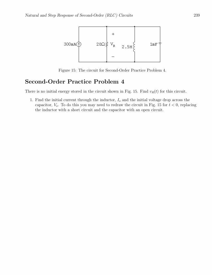
Figure 15: The circuit for Second-Order Practice Problem 4.
Second-Order Practice Problem 4
There is no initial energy stored in the circuit shown in Fig. 15. Find vR(t) for this circuit.
1. Find the initial current through the inductor, Io and the initial voltage drop across thecapacitor, Vo. To do this you may need to redraw the circuit in Fig. 15 for t < 0, replacingthe inductor with a short circuit and the capacitor with an open circuit.

240 Natural and Step Response of Second-Order (RLC) Circuits
2. Find the final current through the inductor, If and the final voltage drop across thecapacitor, Vf . To do this you may need to redraw the circuit in Fig. 15 for t ≥ 0, replacingthe inductor with a short circuit and the capacitor with an open circuit.
3. To find α and ωo, draw the circuit in Fig. 15 for t ≥ 0. Use the values of the resistor,inductor, and capacitor and the appropriate equations for α and ωo. Then compare thevalues of α2 and ω2
o to determine the form of the response. Remember that the responsevariable will be the current in the inductor for the natural response of the series RLC circuitand for the step response of the parallel RLC circuit; the response variable will be thevoltage drop across the capacitor for the natural response of the parallel RLC circuit and forthe step response of the series RLC circuit.

Natural and Step Response of Second-Order (RLC) Circuits 241
4. Write the two equations needed to solve for the coefficients in the response from Step 3. Thefirst equation is constructed by equating the value of the response equation at t = 0 with theinitial condition for the voltage or current from the circuit, in Step 1. The second equationis constructed by equation the value of the first derivative of the response equation at t = 0with the initial condition for the first derivative of the voltage or current in the circuit,which will be determined using additional circuit analysis. Solve the two equations andwrite the final form of the response.
5. If the quantity requested for the circuit in Fig. 15 is the same as the one you calculated inStep 4, you are done. Otherwise, use additional circuit analysis to calculate the quantityrequested in Fig. 15.

242 Natural and Step Response of Second-Order (RLC) Circuits
Figure 16: The circuit for Second-Order Practice Problem 5.
Second-Order Practice Problem 5
Find iL(t) for the circuit shown in Fig. 16.
1. Find the initial current through the inductor, Io and the initial voltage drop across thecapacitor, Vo. To do this you may need to redraw the circuit in Fig. 16 for t < 0, replacingthe inductor with a short circuit and the capacitor with an open circuit.

Natural and Step Response of Second-Order (RLC) Circuits 243
2. Find the final current through the inductor, If and the final voltage drop across thecapacitor, Vf . To do this you may need to redraw the circuit in Fig. 16 for t ≥ 0, replacingthe inductor with a short circuit and the capacitor with an open circuit.
3. To find α and ωo, draw the circuit in Fig. 16 for t ≥ 0. Use the values of the resistor,inductor, and capacitor and the appropriate equations for α and ωo. Then compare thevalues of α2 and ω2
o to determine the form of the response. Remember that the responsevariable will be the current in the inductor for the natural response of the series RLC circuitand for the step response of the parallel RLC circuit; the response variable will be thevoltage drop across the capacitor for the natural response of the parallel RLC circuit and forthe step response of the series RLC circuit.

244 Natural and Step Response of Second-Order (RLC) Circuits
4. Write the two equations needed to solve for the coefficients in the response from Step 3. Thefirst equation is constructed by equating the value of the response equation at t = 0 with theinitial condition for the voltage or current from the circuit, in Step 1. The second equationis constructed by equation the value of the first derivative of the response equation at t = 0with the initial condition for the first derivative of the voltage or current in the circuit,which will be determined using additional circuit analysis. Solve the two equations andwrite the final form of the response.
5. If the quantity requested for the circuit in Fig. 16 is the same as the one you calculated inStep 4, you are done. Otherwise, use additional circuit analysis to calculate the quantityrequested in Fig. 16.

Natural and Step Response of Second-Order (RLC) Circuits 245
Figure 17: The circuit for Second-Order Practice Problem 6.
Second-Order Practice Problem 6
There is no initial energy stored in the circuit shown in Fig. 17. Find iL(t) for this circuit.
1. Find the initial current through the inductor, Io and the initial voltage drop across thecapacitor, Vo. To do this you may need to redraw the circuit in Fig. 17 for t < 0, replacingthe inductor with a short circuit and the capacitor with an open circuit.

246 Natural and Step Response of Second-Order (RLC) Circuits
2. Find the final current through the inductor, If and the final voltage drop across thecapacitor, Vf . To do this you may need to redraw the circuit in Fig. 17 for t ≥ 0, replacingthe inductor with a short circuit and the capacitor with an open circuit.
3. To find α and ωo, draw the circuit in Fig. 17 for t ≥ 0. Use the values of the resistor,inductor, and capacitor and the appropriate equations for α and ωo. Then compare thevalues of α2 and ω2
o to determine the form of the response. Remember that the responsevariable will be the current in the inductor for the natural response of the series RLC circuitand for the step response of the parallel RLC circuit; the response variable will be thevoltage drop across the capacitor for the natural response of the parallel RLC circuit and forthe step response of the series RLC circuit.

Natural and Step Response of Second-Order (RLC) Circuits 247
4. Write the two equations needed to solve for the coefficients in the response from Step 3. Thefirst equation is constructed by equating the value of the response equation at t = 0 with theinitial condition for the voltage or current from the circuit, in Step 1. The second equationis constructed by equation the value of the first derivative of the response equation at t = 0with the initial condition for the first derivative of the voltage or current in the circuit,which will be determined using additional circuit analysis. Solve the two equations andwrite the final form of the response.
5. If the quantity requested for the circuit in Fig. 17 is the same as the one you calculated inStep 4, you are done. Otherwise, use additional circuit analysis to calculate the quantityrequested in Fig. 17.

248 Natural and Step Response of Second-Order (RLC) Circuits
Figure 18: The circuit for Second-Order Practice Problem 7.
Second-Order Practice Problem 7
Find vR(t) for the circuit shown in Fig. 18.
1. Find the initial current through the inductor, Io and the initial voltage drop across thecapacitor, Vo. To do this you may need to redraw the circuit in Fig. 18 for t < 0, replacingthe inductor with a short circuit and the capacitor with an open circuit.

Natural and Step Response of Second-Order (RLC) Circuits 249
2. Find the final current through the inductor, If and the final voltage drop across thecapacitor, Vf . To do this you may need to redraw the circuit in Fig. 18 for t ≥ 0, replacingthe inductor with a short circuit and the capacitor with an open circuit.
3. To find α and ωo, draw the circuit in Fig. 18 for t ≥ 0. Use the values of the resistor,inductor, and capacitor and the appropriate equations for α and ωo. Then compare thevalues of α2 and ω2
o to determine the form of the response. Remember that the responsevariable will be the current in the inductor for the natural response of the series RLC circuitand for the step response of the parallel RLC circuit; the response variable will be thevoltage drop across the capacitor for the natural response of the parallel RLC circuit and forthe step response of the series RLC circuit.

250 Natural and Step Response of Second-Order (RLC) Circuits
4. Write the two equations needed to solve for the coefficients in the response from Step 3. Thefirst equation is constructed by equating the value of the response equation at t = 0 with theinitial condition for the voltage or current from the circuit, in Step 1. The second equationis constructed by equation the value of the first derivative of the response equation at t = 0with the initial condition for the first derivative of the voltage or current in the circuit,which will be determined using additional circuit analysis. Solve the two equations andwrite the final form of the response.
5. If the quantity requested for the circuit in Fig. 18 is the same as the one you calculated inStep 4, you are done. Otherwise, use additional circuit analysis to calculate the quantityrequested in Fig. 18.

Natural and Step Response of Second-Order (RLC) Circuits 251
Figure 19: The circuit for Second-Order Practice Problem 8.
Second-Order Practice Problem 8
Find vL(t) for the circuit shown in Fig. 19.
1. Find the initial current through the inductor, Io and the initial voltage drop across thecapacitor, Vo. To do this you may need to redraw the circuit in Fig. 19 for t < 0, replacingthe inductor with a short circuit and the capacitor with an open circuit.

252 Natural and Step Response of Second-Order (RLC) Circuits
2. Find the final current through the inductor, If and the final voltage drop across thecapacitor, Vf . To do this you may need to redraw the circuit in Fig. 19 for t ≥ 0, replacingthe inductor with a short circuit and the capacitor with an open circuit.
3. To find α and ωo, draw the circuit in Fig. 19 for t ≥ 0. Use the values of the resistor,inductor, and capacitor and the appropriate equations for α and ωo. Then compare thevalues of α2 and ω2
o to determine the form of the response. Remember that the responsevariable will be the current in the inductor for the natural response of the series RLC circuitand for the step response of the parallel RLC circuit; the response variable will be thevoltage drop across the capacitor for the natural response of the parallel RLC circuit and forthe step response of the series RLC circuit.

Natural and Step Response of Second-Order (RLC) Circuits 253
4. Write the two equations needed to solve for the coefficients in the response from Step 3. Thefirst equation is constructed by equating the value of the response equation at t = 0 with theinitial condition for the voltage or current from the circuit, in Step 1. The second equationis constructed by equation the value of the first derivative of the response equation at t = 0with the initial condition for the first derivative of the voltage or current in the circuit,which will be determined using additional circuit analysis. Solve the two equations andwrite the final form of the response.
5. If the quantity requested for the circuit in Fig. 19 is the same as the one you calculated inStep 4, you are done. Otherwise, use additional circuit analysis to calculate the quantityrequested in Fig. 19.
254 Natural and Step Response of Second-Order (RLC) Circuits
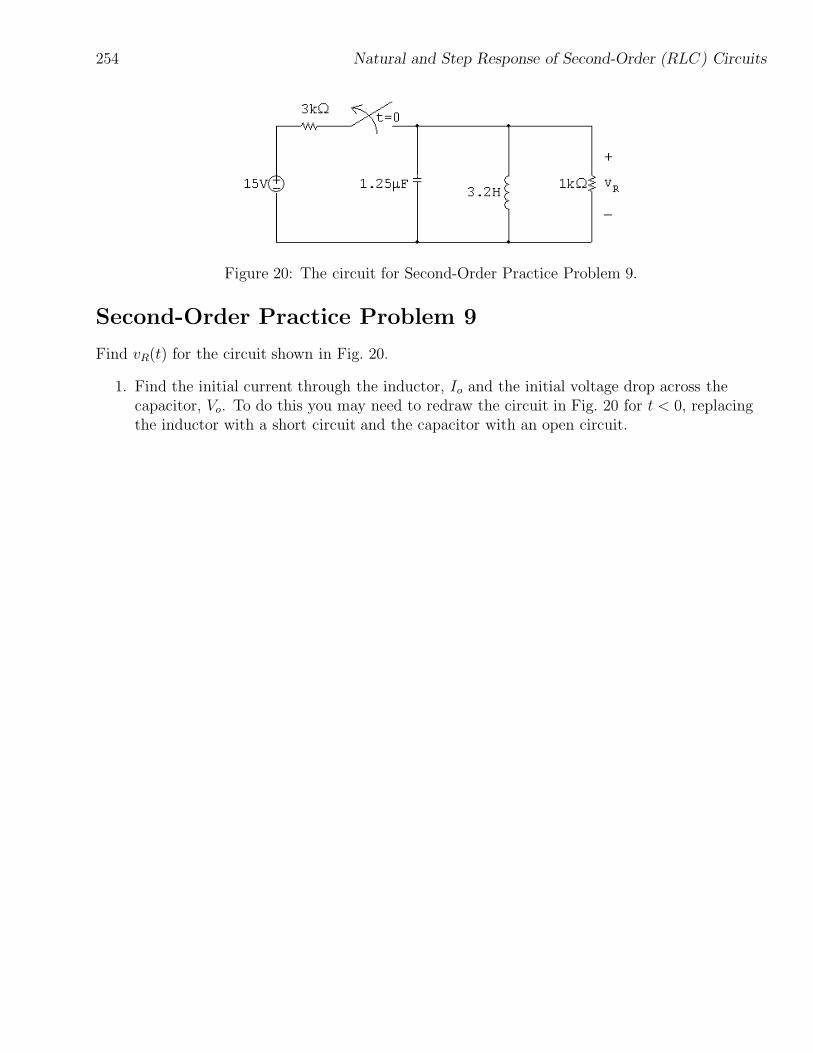
Figure 20: The circuit for Second-Order Practice Problem 9.
Second-Order Practice Problem 9
Find vR(t) for the circuit shown in Fig. 20.
1. Find the initial current through the inductor, Io and the initial voltage drop across thecapacitor, Vo. To do this you may need to redraw the circuit in Fig. 20 for t < 0, replacingthe inductor with a short circuit and the capacitor with an open circuit.

Natural and Step Response of Second-Order (RLC) Circuits 255
2. Find the final current through the inductor, If and the final voltage drop across thecapacitor, Vf . To do this you may need to redraw the circuit in Fig. 20 for t ≥ 0, replacingthe inductor with a short circuit and the capacitor with an open circuit.
3. To find α and ωo, draw the circuit in Fig. 20 for t ≥ 0. Use the values of the resistor,inductor, and capacitor and the appropriate equations for α and ωo. Then compare thevalues of α2 and ω2
o to determine the form of the response. Remember that the responsevariable will be the current in the inductor for the natural response of the series RLC circuitand for the step response of the parallel RLC circuit; the response variable will be thevoltage drop across the capacitor for the natural response of the parallel RLC circuit and forthe step response of the series RLC circuit.

256 Natural and Step Response of Second-Order (RLC) Circuits
4. Write the two equations needed to solve for the coefficients in the response from Step 3. Thefirst equation is constructed by equating the value of the response equation at t = 0 with theinitial condition for the voltage or current from the circuit, in Step 1. The second equationis constructed by equation the value of the first derivative of the response equation at t = 0with the initial condition for the first derivative of the voltage or current in the circuit,which will be determined using additional circuit analysis. Solve the two equations andwrite the final form of the response.
5. If the quantity requested for the circuit in Fig. 20 is the same as the one you calculated inStep 4, you are done. Otherwise, use additional circuit analysis to calculate the quantityrequested in Fig. 20.

Natural and Step Response of Second-Order (RLC) Circuits 257
Reading
• in Electric Circuits, ninth edition:
– Section 8.1 — natural response of parallel RLC circuits
– Section 8.2 — forms of the natural response
– Section 8.3 — step response of parallel RLC circuits
– Section 8.4 — natural and step response of series RLC circuits
Additional Problems
• 8.2 — 8.4
• 8.18 — 8.23
• 8.27
• 8.29 — 8.38
• 8.44 — 8.53
• 8.56
Solutions
• Second-Order Practice Problem 1:
α = 800 rad/sec; ωo = 1000 rad/sec;
vC(t) = 30 − (30 cos 600t + 40 sin 600t)e−800t V, t ≥ 0
• Second-Order Practice Problem 2:
α = 50 rad/sec; ωo = 40 rad/sec;
iR(t) = 40e−80t − 40e−20t mA, t ≥ 0
• Second-Order Practice Problem 3:
α = 5000 rad/sec; ωo = 5000 rad/sec;
iL(t) = 5e−5000t + 50,000te−5000t mA, t ≥ 0

258 Natural and Step Response of Second-Order (RLC) Circuits
• Second-Order Practice Problem 4:
α = 25 rad/sec; ωo = 20 rad/sec;
vR(t) = 10e−10t − 10e−40t V, t ≥ 0
• Second-Order Practice Problem 5:
α = 2400 rad/sec; ωo = 2500 rad/sec;
iL(t) = −100 sin 700te−2400t A, t ≥ 0
• Second-Order Practice Problem 6:
α = 1000 rad/sec; ωo = 1000 rad/sec;
iL(t) = 50 − 50,000te−1000t − 50e−1000t mA, t ≥ 0
• Second-Order Practice Problem 7:
α = 2500 rad/sec; ωo = 2000 rad/sec;
vR(t) = 500e−1000t − 2000e−4000t V, t ≥ 0
• Second-Order Practice Problem 8:
α = 25,000 rad/sec; ωo = 25,000 rad/sec;
vL(t) = 12e−25,000t − 300,000te−25,000t V, t ≥ 0
• Second-Order Practice Problem 9:
α = 400 rad/sec; ωo = 500 rad/sec;
vR(t) = −13.33 sin 300te−400t V, t ≥ 0