natural gas pipeline workshop presentation
TRANSCRIPT
California Energy Commission California Energy Commission Hearing Room BHearing Room B
August 7, 2012August 7, 2012
IntroductionIntroductionGoalsPIER ApproachPIER ApproachBest Practices in Monitoring Technology (GTI)Innovative Monitoring Technologies (CITRIS)Innovative Monitoring Technologies (CITRIS)LunchRecommended Areas of Emphasis forRecommended Areas of Emphasis for Solicitation Panel DiscussionsWorkshop Conclusion and Next Stepsp pQuestions and Comments
2

Mike Gravely – Deputy Division ChiefFernando Piña – Energy Systems Integration Office (ESRO)
ManagerJamie Patterson – ESRO Team LeadJohann Karkheck Energy Technology Systems IntegrationJohann Karkheck – Energy Technology Systems Integration
Contract Manager
Paul Wright – Principal Investigatorg p gDick White – Principal EngineerGaymond Yee – Research CoordinatorIgor Paprotny – Technical Project Manager
James Marean – Principal Investigator (Teleconference)A d H h idt P j t M (T l f )Andrew Hammerschmidt – Project Manager (Teleconference)
3
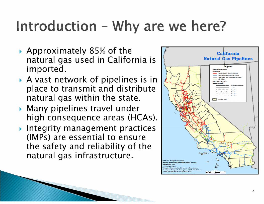
Approximately 85% of theApproximately 85% of the natural gas used in California is imported.A t t k f i li i iA vast network of pipelines is in place to transmit and distribute natural gas within the state.gMany pipelines travel under high consequence areas (HCAs).Integrity management practicesIntegrity management practices (IMPs) are essential to ensure the safety and reliability of the natural gas infrastructure.
4
Various legislation has set standards for IMPs:Various legislation has set standards for IMPs:◦ 49 CFR Part 192 Subpart O, Pipeline Safety
Improvement Act of 2002, PIPES Act of 2006, l l f fNational Pipeline Safety Act of 2011, etc.
Research, Development and Demonstration are needed to provide tools to enhanceare needed to provide tools to enhance operator’s IMPs. In 2011 in consultation with the CaliforniaIn 2011, in consultation with the California Public Utilities Commission, the PIER program selected CITRIS and GTI to conduct research on natural gas pipeline inspection technology.
5
OverarchingOverarching◦ The general goal is to develop, and help bring to
market energy technologies that provide increasedmarket, energy technologies that provide increased system awareness and reliability, lower system costs, and that provide tangible benefits to California utility customers.
Today◦ Present the current research on technologies used
for pipeline integrity and monitoring practicesl f h l◦ Evaluate suggestions for technologies to pursue in
the upcoming solicitation
6
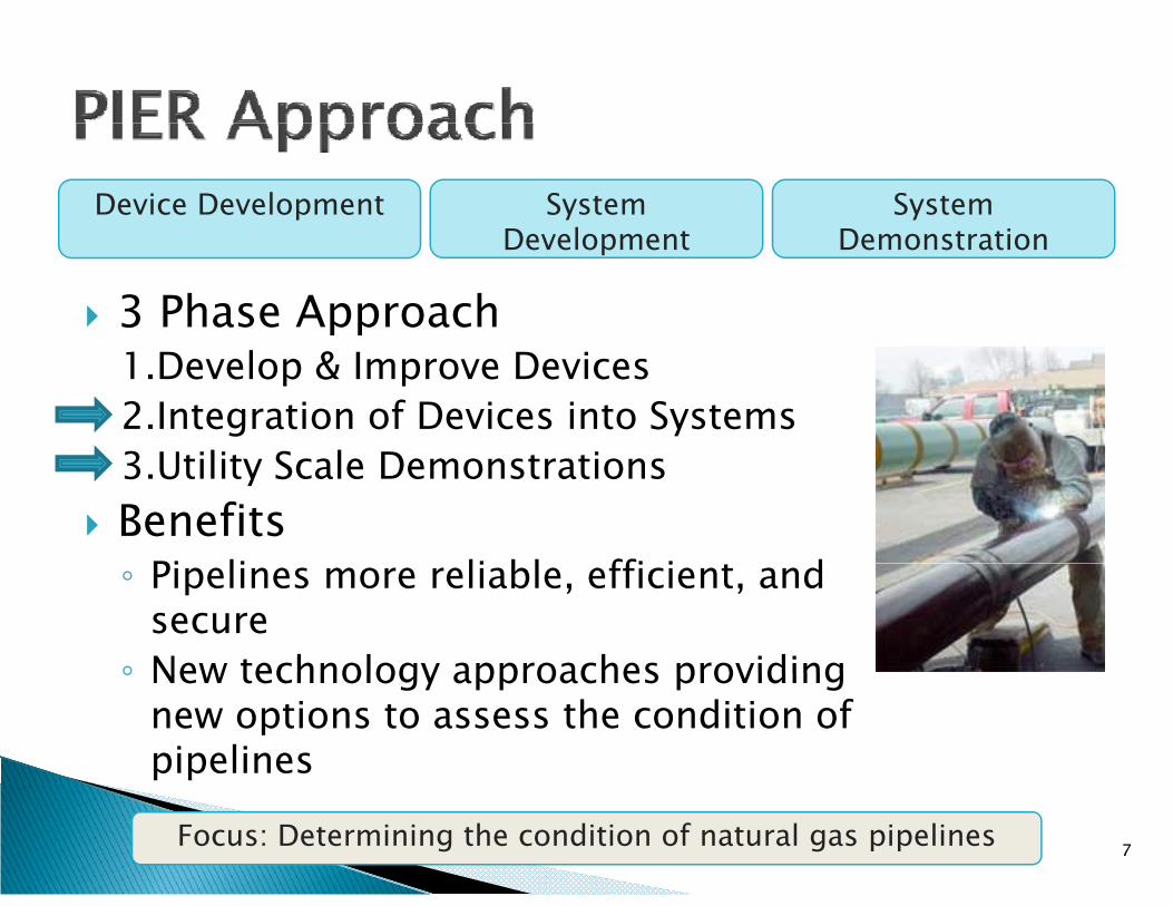
Device Development System D l t
System D t ti
3 Phase ApproachDevelopment Demonstration
1.Develop & Improve Devices2.Integration of Devices into Systems3 U ili S l D i3.Utility Scale DemonstrationsBenefits
Pi li li bl ffi i d◦ Pipelines more reliable, efficient, and secure◦ New technology approaches providing◦ New technology approaches providing
new options to assess the condition of pipelines
Focus: Determining the condition of natural gas pipelines 7
CALIFORNIA NATURAL GAS PIPELINE ASSESSMENT - CEC #500-10-050
PIPELINE INTEGRITY and MONITORING TECHNOLOGY ASSESSMENTTECHNOLOGY ASSESSMENT
GTI Project Review
Natural Gas Pipeline Research Workshop
August 7, 2012
8
P j t G l SProject Goals - Summary
>Identify Quick “Wins” Commercial Technologies Not in Use That Could/Should Be
>Emerging Technologies That Could Be Moved e g g ec o og es at Cou d e o edto Commercial Availability Quicker
>Leverage and Optimize the Use of the>Leverage and Optimize the Use of the Advanced Metering Infrastructure (AMI)
>Develop an Implementation Plan
9 9
TASKS d DELIVERABLESTASKS and DELIVERABLES
> Baseline Technology Assessment in the State of CaliforniaBaseline Technology Assessment in the State of California─ Review of current state of technologies being used─ Completed – April 30, 2012
> Assessment of Currently Available Technologyy gy─ Catalogue of available technologies─ Gap analysis─ Completed – July 31, 2012
> Evaluate Emerging Technology─ Identify technologies that could be developed or enhanced in the next 2-4 years─ Emphasis on integration with the AMI communications backbone─ Scheduled Completion Date – October 31 2012Scheduled Completion Date October 31, 2012
> Implementation Plan─ Recommend specific technologies to implement in a timely and cost effective manner
> Testing and deployment currently available technologiesTesting and deployment currently available technologies> Development of select emerging technologies> Development of new technologies to meet outstanding gaps
─ Scheduled Completion Date – February 28, 2013
10 10
T k 2 B li A t O iTask 2 – Baseline Assessment - Overview
>S mmari ed the Nat ral Gas Pipeline S stem>Summarized the Natural Gas Pipeline System>Interviewed Pipeline Operators to:
Identify all Pipeline Integrity Technologies in Use─ Identify all Pipeline Integrity Technologies in Use─ Determine if:
> There Were Any Technologies Used in the Past That y gWere No Longer in Use
> Any Commercially Available Technologies Were Being Evaluated for Future Use
> They Were Involved in the Development of New or Replacement Technologies
─ Asked for Their “Wish List”Asked for Their Wish List>Technologies Placed in one of 11 Categories
11 11
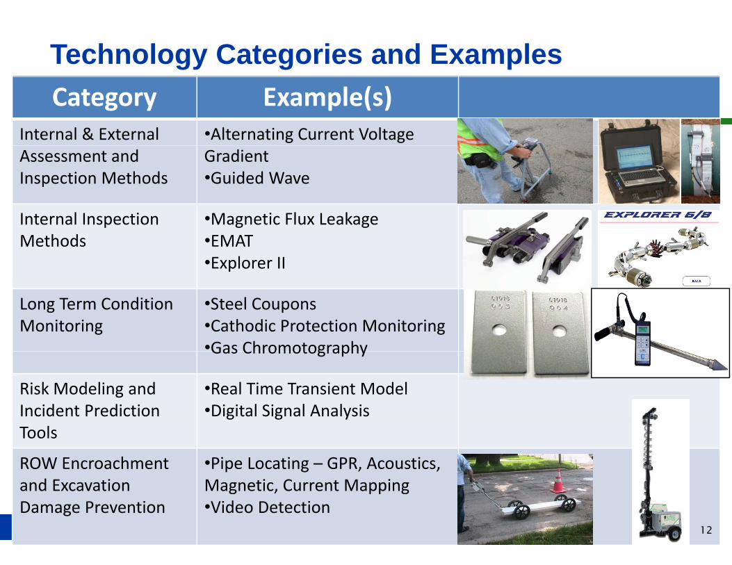
Technology Categories and ExamplesCategory Example(s)
Internal & External •Alternating Current Voltage Assessment and Inspection Methods
Gradient•Guided Wave
I t l I ti M ti Fl L kInternal Inspection Methods
•Magnetic Flux Leakage•EMAT•Explorer II
Long Term Condition Monitoring
•Steel Coupons•Cathodic Protection Monitoring•Gas ChromotographyGas Chromotography
Risk Modeling and Incident Prediction
•Real Time Transient Model•Digital Signal Analysis
Tools
ROW Encroachment and Excavation
•Pipe Locating – GPR, Acoustics, Magnetic Current Mapping
12
and Excavation Damage Prevention
Magnetic, Current Mapping•Video Detection
12
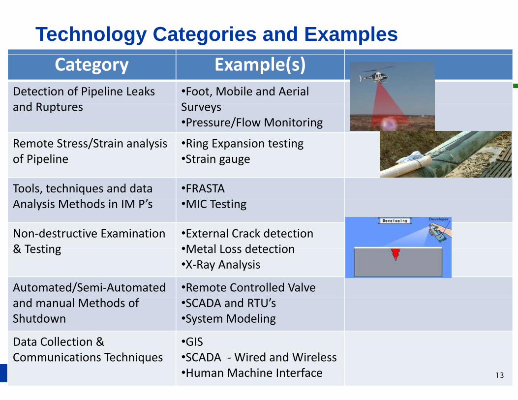
Technology Categories and ExamplesCategory Example(s)
Detection of Pipeline Leaks d R
•Foot, Mobile and Aerial Sand Ruptures Surveys•Pressure/Flow Monitoring
Remote Stress/Strain analysis •Ring Expansion testingof Pipeline •Strain gauge
Tools, techniques and data A l i M h d i IM P’
•FRASTAMIC T iAnalysis Methods in IM P’s •MIC Testing
Non‐destructive Examination & Testing
•External Crack detection•Metal Loss detection& Testing •Metal Loss detection•X‐Ray Analysis
Automated/Semi‐Automated •Remote Controlled Valveand manual Methods of Shutdown
•SCADA and RTU’s•System Modeling
Data Collection & •GIS
13
a a o ec oCommunications Techniques
S•SCADA ‐Wired and Wireless•Human Machine Interface 13
“Wish List” - Technologies Needing Creation orWish List Technologies Needing Creation or Enhancement (1)
>Impro ed Leak S r e Technologies>Improved Leak Survey Technologies>Fiber Optic Cabling for Monitoring Pipeline Right of
Way (ROW) IntrusionWay (ROW) Intrusion>Use AMI for:
─ Real-time methane detection System Flow and PressureReal-time methane detection, System Flow and Pressure Monitoring
─ Pipeline monitoring, and back-up (redundant path, emergency only) operation of selected valvesemergency only) operation of selected valves
─ A low cost approach to move the data>Enhancement to LiDAREnhancement to LiDAR>Crack Sensor Detectors – on the 24 inch PIPETEL
tool
14 14
“Wish List” - Technologies Needing Creation orWish List Technologies Needing Creation or Enhancement (2)
> Improve the Value of EMAT Technology Use a Needs Assessment> Improve the Value of EMAT Technology - Use a Needs Assessment > Automated Girth Weld Inspection Tool on a Tether> Robotic ILI Tools for Medium and Large Diameter Pipelines that are> Robotic ILI Tools for Medium and Large Diameter Pipelines that are
Un-Piggable with Conventional Tools> Alternative Acoustic Pipeline/ROW Intrusion Monitoring Technologies> Real time modeling systems with an On-Line Analysis Tool
─ New ways to control the pipeline─ Model the system─ Use real-time data to gain intelligence─ Identify risks as they develop
> Replacement Tool for the Existing GIS – Need a fundamental change p g gto the data model and how the model is structured─ Real-time monitoring─ Analysis tools that integrate enterprise tools with GIS to know “what’s”
“where”
15
where
15
“Wish List” - Technologies Needing Creation orWish List Technologies Needing Creation or Enhancement (3)
T l t A t l M C k L th d D th i> Tool to Accurately Measure Crack Length and Depth in the Ditch
> Assessment of Long Seams and Girth Welds> Assessment of Long Seams and Girth Welds> Industry Database Available to Others for Trend Analysis
and Threat Identificationand Threat Identification> Predictive Performance Based (Proactive) Modeling Tool
─ Integrate Company/Industry data─ Integrate Company/Industry data─ Improve effective decision making─ Provide a programmatic decision method rather than a
i ti ( ti ) d th dprescriptive (reactive) man-made method─ Assist in identifying efficiency improvements─ Supplement the man-made decision making method
16
pp g
16
“Wish List” - Technologies Needing Creation orWish List Technologies Needing Creation or Enhancement (4)
>Low Cost and Low Power Monitoring and Communicating Technology for Remote Applications to Expand the SCADA System
>Method to Integrate SCADA System with the GISe od o eg a e SC Sys e e G S─ Define Point Information Once and Populate with
Field Data
>Mobile Technology - Field Tablets for EmployeesReal time data to and from the field eliminate paper─ Real time data to and from the field, eliminate paper and provide a single point of entry to the database
17 17
T k 2 S R lt d K Fi diTask 2 Survey Results and Key Findings
SME’ D l d M i t i IMP’ S ifi t th>SME’s Develop and Maintain IMP’s Specific to the Needs of Each OperatorN t E T h l i A i t P id>Not Every Technology is Appropriate or Provides Value in Every InstanceT h l i d d b i b th>Technologies needed by some were in use by others─ Crack Measurement in the Ditch
Hand Held Field Data Collection Devices─ Hand-Held Field Data Collection Devices
>A Lessons Learned/Brainstorming Workshop Should Have Immediate BenefitsHave Immediate Benefits
>Facilities Are Available for Testing and Verification
18 18
T k 3 C tl A il bl A t O i (1)Task 3 – Currently Available Assessment – Overview (1)
C t l f T h l i>Catalogue of Technologies─ Tools, Processes and Systems for Monitoring
> 11 Categories> 11 Categories– Description– Strengthsg– Weaknesses– Pictures – if Applicable– Provider - if Limited Number– Communications Capability
References– References─ List of Acronyms─ Glossary of Terms
19
G ossa y o e s
19
T k 3 C tl A il bl A t O i (2)Task 3 – Currently Available Assessment – Overview (2)
>Gap Analysis─ Weaknesses─ Communications Capability─ From Interviews During Task 2
> Previously Used> Being evaluated for Use> “Wish List”
─ Input from SME’s─ Pipeline Assessment Technology Workshop
20 20
T k 3 Pi li A t T h l W k hTask 3 - Pipeline Assessment Technology Workshop
─ Purpose - to identify the needs and gaps in existing or emerging transmission pipeline assessment and monitoring technologiesmonitoring technologies
─ Conducted June 5-6, 2012Included─ Included
> California Pipeline Operators> INGAA Interstate Natural Gas Association of> INGAA – Interstate Natural Gas Association of
America> GTI Gas Technology Institute> GTI – Gas Technology Institute> PRCI – Pipeline Research Council International
21 21
F d F Th ht 1Food For Thought - 1
T Th N d G C>Top Three Needs, Gaps, Concerns>No Technology with the Capability of Interest>Used in Another Industry But Not in Natural Gas>Short Comings:Short Comings:
─ Detection Limits─ Missing Parameters of Interest/Concern─ Cumbersome or Difficult to Use
>Information Technology Requirements>Database Issues
─ SCADA with GIS, GIS with Stoner
22
,
22

F d F Th ht 2Food For Thought - 2
>Communications Limitations─ Proprietary vs. Interoperable─ Different Generations─ Varying Ability – How Much, How Frequent, What
Language, Level of Sensitivity, Accuracy vs Precision, Storage is too Small, Timeliness of Data Refresh –“What is Real Now?” “10 000 Versions of the Truth!”What is Real Now? 10,000 Versions of the Truth!
─ None Available for Device of InterestOne Way vs Two Way─ One-Way vs. Two-Way
─ Limited Availability – Cellular, RF, Satellite
23 23
Pi li A t T h l W k h O tPipeline Assessment Technology Workshop - Outcome
E G l /R d f th 3 I d t R&D G> Ensure Goals/Roadmaps of the 3 Industry R&D Groups are Aligned
> Commercially Available Not Useful Due to Operational or> Commercially Available Not Useful Due to Operational or Regulatory Barriers – “Prove it, Get it Accepted”
> Need the Three Legs of the Stool – Industry, Regulators g y, gand Manufacturers
> What’s Missing> Standard of Acceptance – Operator Regulator> Standard of Acceptance Operator, Regulator
> Three Areas of Focus For Rapid Deployment1. ROW Encroachment and Excavation Damage Prevention1. ROW Encroachment and Excavation Damage Prevention2. Alternate Inspection Technologies3. Education
24 24
ROW Encroachment & Excavation Damage PreventionROW Encroachment & Excavation Damage Prevention (1)
>Know When Someone is on the ROW>Cost Effective Retrofit for Existing ROWCost Effective Retrofit for Existing ROW
─ Focus on HCA’s─ Fence Post ApproachFence Post Approach
>New Installations>Visual or Vibration>Date/Time Stamped>Date/Time Stamped>Record Events for Download
25 25
ROW Encroachment & Excavation Damage PreventionROW Encroachment & Excavation Damage Prevention (2)
>Below or at Ground Level>Below or at Ground Level─ Wet or Dry─ Acoustics─ Fiber─ Other
> Pressure Sensor as a Microphone> Pressure Sensor as a Microphone> Visual Recognition
>AerialAerial─ Fixed Wing─ Helicopter
U d─ Unmanned>Satellite
26 26

Alt t I ti T h l iAlternate Inspection Technologies
> Focus on Alternative to Hydro Test Piggable and Non> Focus on Alternative to Hydro Test – Piggable and Non-Piggable─ No Water─ Leak/Rupture Boundary - Threat/Risk, Likely failure –
Probability/Severity─ Virtual Records - Industry Database – Common Threads─ Guided Wave – Address PHMSA’s 18 Points
> http://primis.phmsa.dot.gov/gasimp/docs/GuidedWaveCheckList110107.pdf
─ Non-Piggable Assessment Tools> Robotics> Non-Invasive Data Collection Techniquesq
─ ILI Decision Matrix/Assessment Tool Guidelines> 30+ ILI Vendors> Multiple Tool(s)/Pig
27
Multiple Tool(s)/Pig
27
Ed tiEducation
> Needs> Needs─ Primer on Integrity Management – Non-Industry Author─ Situational Awareness – Emergency Responders and Public─ Real Time Knowledge to the Situation – Video Link to Advisor─ Training and Retention of Workforce
> Need a Larger Pool – Education System with Degree g y gPrograms
> Documented Process, Training Matrix, Improved Delivery Format – New Generation of Learning Styles
> Audience─ Emergency Responders
Public─ Public─ Regulators─ Employees
28 28
Additi l O t iti 12 M th t D lAdditional Opportunities – 12 Months to Deploy
> Hand held devices for field use> Hand-held devices for field use
> Integration of field data immediately into a GIS
> Survey grade GPS w/o post-processing immediately into a GIS
> Bar coding to optimize and automate field data collection
> Radio Frequency Identification (RFID) tags to locate facilities and collect and store field data for later processing
> A lessons learned and technology demonstration workshop
> An industry database as the first step toward the development of a predictive performance based (proactive)
29
modeling tool29
Additi l O t iti 12 24 M th t D l (1)Additional Opportunities – 12 - 24 Months to Deploy (1)
> Upgraded and integrated GIS with enterprise software> Upgraded and integrated GIS with enterprise software available to the field “Make My Pipeline Like My House – Where is my stuff, I want to control it”
> Accurate measurement of crack length and depth in the ditch with transmittal to the back office
> Predictive performance based modeling tool integrated with an industry database to supplement man-made decision makingdecision making
> Remote, low cost methane detectors in the 100 to 200 ppm range and providing an alarmppm range and providing an alarm
> Tracking and work management software for HCA’s as accurate and reliable as “boots on the ground”
30
accurate and reliable as boots on the ground30
Additi l O t iti 12 24 M th t D l (2)Additional Opportunities – 12 - 24 Months to Deploy (2)
>L t l t h l i t ll>Low cost, low power technologies at smaller intervals - an accurate “picture” in real-time
>Requires verification of the AMI and sensor capabilities:─ AMI has redundancy and security in the areas of
sensor deployment ─ Full access to and inter-operability of the AMI system─ Cost advantage of sensors under development─ Full inter-operability of the all sensors
31 31
Additi l O t iti 12 24 M th t D l (3)Additional Opportunities – 12 - 24 Months to Deploy (3)
>O ifi d th AMI t t id>Once verified use the AMI system to provide:─ Redundant two-way communications for data flow─ Data collection, monitoring and system control as new
technologies are developed – Ex. Right-of-Way (ROW) encroachment and excavation damage(ROW) encroachment and excavation damage prevention, leak detection
─ Improved real-time monitoring of flow and pressureImproved real time monitoring of flow and pressure─ Improved operation of selected valves─ Instantaneous identification of an issue or failureInstantaneous identification of an issue or failure
requiring pipeline shutdown
32 32

QUESTIONS???
33
Natural Gas Pipeline Sensors
CEC R&D Roadmap Workshop
Tuesday August 7th, 2012
Dr. Igor Paprotny (EECS/BSAC)
Adam Tornheim (MSME)
Prof. Paul Wright (ME/CITRIS)
Gaymond Yee (CIEE)Prof. Dick White (EECS/BSAC)
Yiping Zhu (EECS/BSAC) ( )Fabien Chimrai (EECS/BSAC)
p g ( )
Prof. Kris Pister (EECS/BSAC)
34
Agenda
Overview
Ti liTimeline
Progress/Status: MEMS Wireless Sensor ModulesLaser Ultrasonic Testing (LUT) and other lt i di ti th dultrasonic diagnostic methods
35
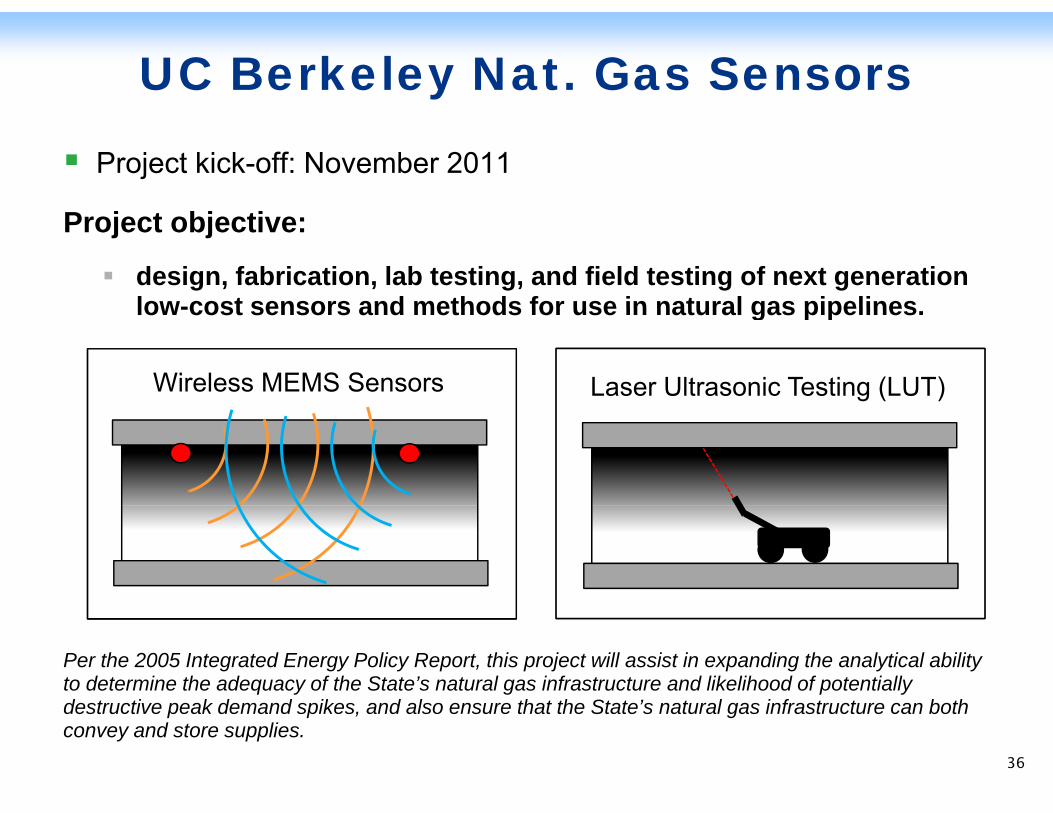
UC Berkeley Nat. Gas Sensors
Project kick-off: November 2011
Project objective:
design, fabrication, lab testing, and field testing of next generation low-cost sensors and methods for use in natural gas pipelineslow-cost sensors and methods for use in natural gas pipelines.
Wireless MEMS Sensors Laser Ultrasonic Testing (LUT)
Per the 2005 Integrated Energy Policy Report, this project will assist in expanding the analytical ability to determine the adequacy of the State’s natural gas infrastructure and likelihood of potentially d t ti k d d ik d l th t th St t ’ t l i f t t b thdestructive peak demand spikes, and also ensure that the State’s natural gas infrastructure can both convey and store supplies.
36
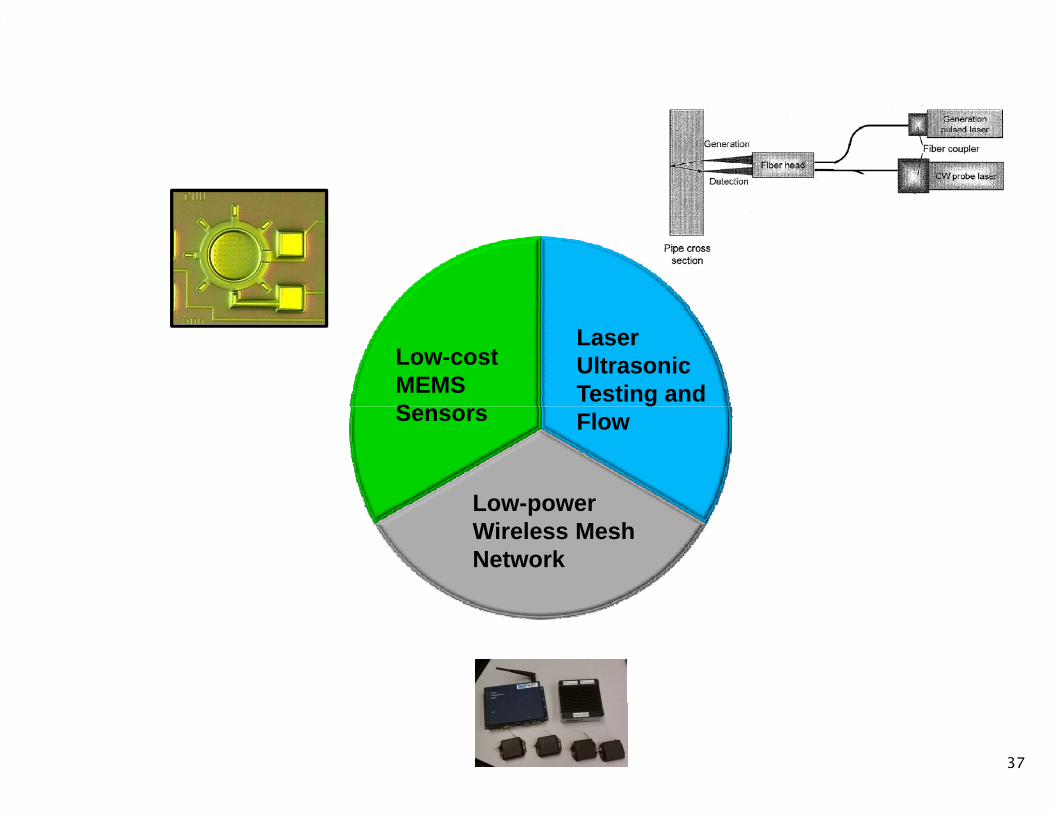
LaserUltrasonicTesting and
Low-cost MEMS S FlowSensors
Low-powerLow-power Wireless Mesh Network
37
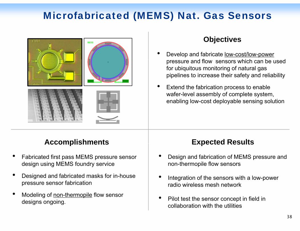
Microfabricated (MEMS) Nat. Gas Sensors
Objectives
• Develop and fabricate low-cost/low-powerd fl hi h b dpressure and flow sensors which can be used
for ubiquitous monitoring of natural gas pipelines to increase their safety and reliability
• Extend the fabrication process to enableExtend the fabrication process to enable wafer-level assembly of complete system, enabling low-cost deployable sensing solution
Accomplishments Expected ResultsAccomplishments
• Fabricated first pass MEMS pressure sensor design using MEMS foundry service
Expected Results
• Design and fabrication of MEMS pressure and non-thermopile flow sensors
• Designed and fabricated masks for in-house pressure sensor fabrication
• Modeling of non-thermopile flow sensor d i i
• Integration of the sensors with a low-power radio wireless mesh network
• Pilot test the sensor concept in field in
38
designs ongoing. Pilot test the sensor concept in field in collaboration with the utilities
38
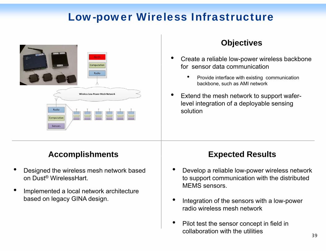
Low-power Wireless Infrastructure
Objectives
• Create a reliable low-power wireless backbone f d t i tifor sensor data communication
• Provide interface with existing communication backbone, such as AMI network
• Extend the mesh network to support wafer• Extend the mesh network to support wafer-level integration of a deployable sensing solution
Accomplishments Expected ResultsAccomplishments
• Designed the wireless mesh network based on Dust® WirelessHart.
Expected Results
• Develop a reliable low-power wireless network to support communication with the distributed MEMS sensors• Implemented a local network architecture
based on legacy GINA design.
MEMS sensors.
• Integration of the sensors with a low-power radio wireless mesh network
39
• Pilot test the sensor concept in field in collaboration with the utilities
39
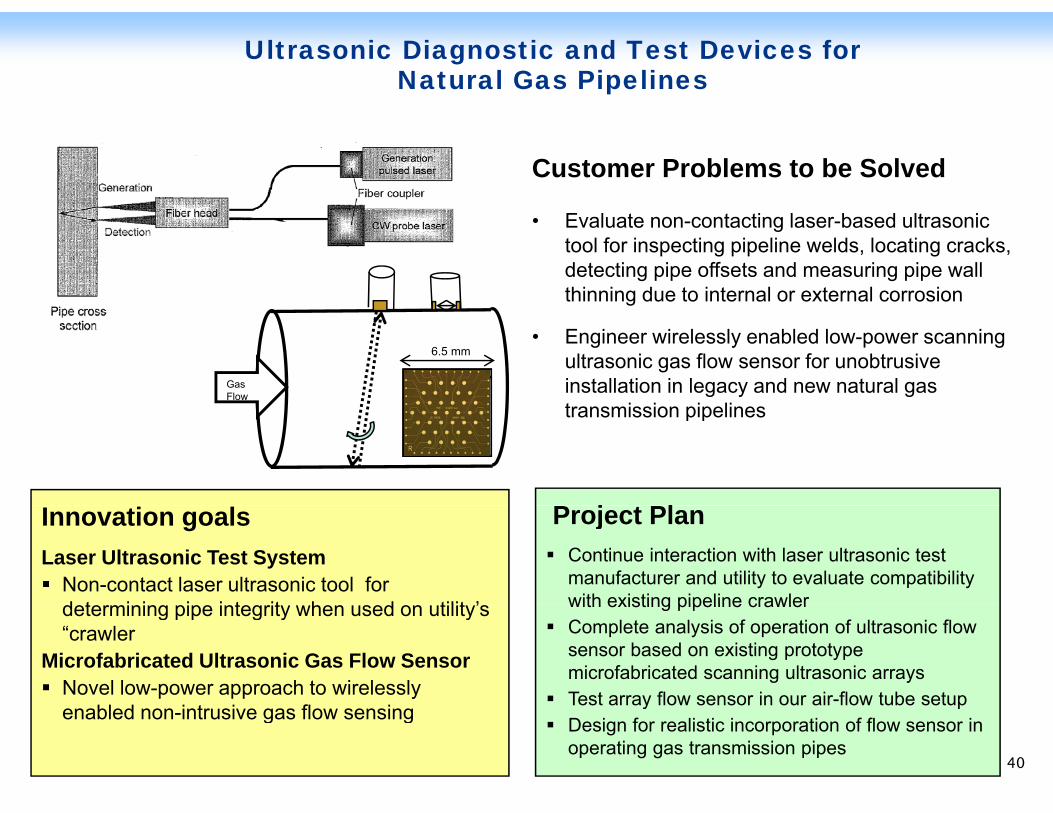
Ultrasonic Diagnostic and Test Devices for Natural Gas Pipelines
Customer Problems to be Solved
• Evaluate non-contacting laser-based ultrasonic tool for inspecting pipeline welds, locating cracks, detecting pipe offsets and measuring pipe wall thinning due to internal or external corrosion
• Engineer wirelessly enabled low-power scanning ultrasonic gas flow sensor for unobtrusive installation in legacy and new natural gas transmission pipelines
Gas Flow v
6.5 mm
P j Pl
transmission pipelines
Innovation goalsLaser Ultrasonic Test System
Non-contact laser ultrasonic tool for d t i i i i t it h d tilit ’
Project PlanContinue interaction with laser ultrasonic test manufacturer and utility to evaluate compatibility with existing pipeline crawlerdetermining pipe integrity when used on utility’s
“crawlerMicrofabricated Ultrasonic Gas Flow Sensor
Novel low-power approach to wirelessly
with existing pipeline crawlerComplete analysis of operation of ultrasonic flow sensor based on existing prototype microfabricated scanning ultrasonic arraysTest array flow sensor in our air-flow tube setup
40
enabled non-intrusive gas flow sensingTest array flow sensor in our air flow tube setupDesign for realistic incorporation of flow sensor in operating gas transmission pipes
40
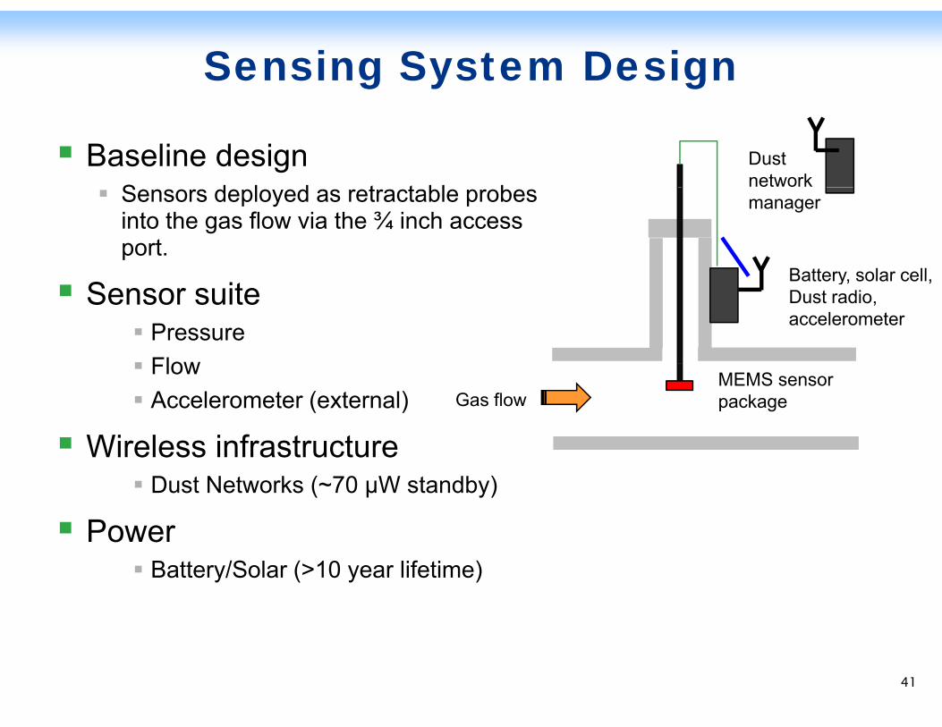
Sensing System Design
Baseline designS d l d t t bl b
Dust network Sensors deployed as retractable probes
into the gas flow via the ¾ inch access port.
Battery solar cell
manager
Sensor suitePressureFlow
Battery, solar cell, Dust radio, accelerometer
FlowAccelerometer (external)
Wireless infrastructureGas flow
MEMS sensor package
Wireless infrastructureDust Networks (~70 µW standby)
PowerPowerBattery/Solar (>10 year lifetime)
41
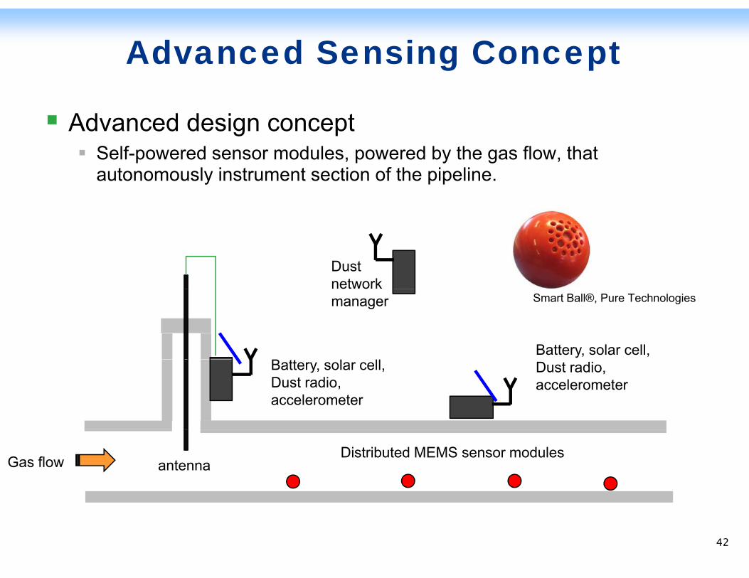
Advanced Sensing Concept
Advanced design conceptS lf d d l d b th fl th tSelf-powered sensor modules, powered by the gas flow, that autonomously instrument section of the pipeline.
Dust network manager
Battery, solar cell,
Smart Ball®, Pure Technologies
Battery, solar cell, Dust radio, accelerometer
Dust radio, accelerometer
Gas flow Distributed MEMS sensor modulesantenna
42
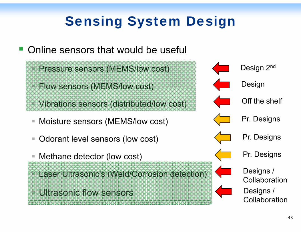
Sensing System Design
Online sensors that would be useful
Pressure sensors (MEMS/low cost)
Flow sensors (MEMS/low cost)
Design 2nd
DesignFlow sensors (MEMS/low cost)
Vibrations sensors (distributed/low cost)
P D i
g
Off the shelf
Moisture sensors (MEMS/low cost)
Odorant level sensors (low cost)
Pr. Designs
Pr. Designs
Methane detector (low cost)
Laser Ultrasonic's (Weld/Corrosion detection)
Pr. Designs
Designs /Laser Ultrasonic's (Weld/Corrosion detection)
Ultrasonic flow sensors
Designs / CollaborationDesigns / CollaborationCollaboration
43
Low-cost MEMS Sensors
44 44
Low-cost MEMS Sensors
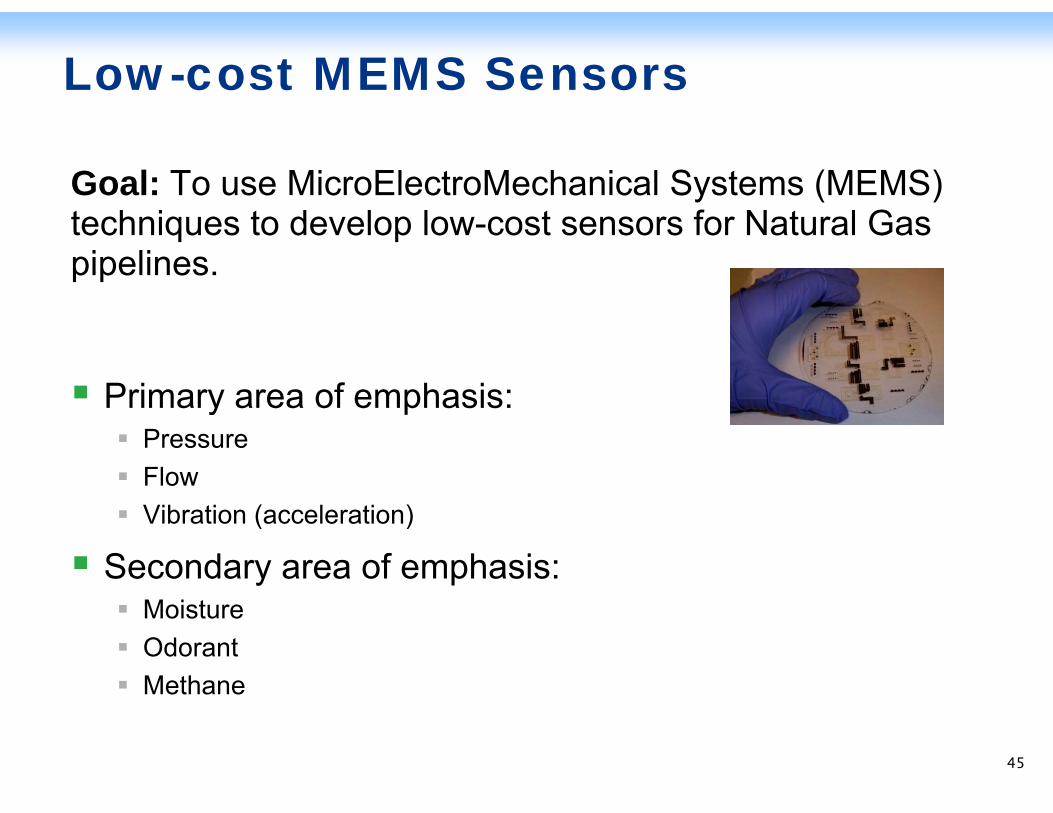
Goal: To use MicroElectroMechanical Systems (MEMS) techniques to develop low-cost sensors for Natural Gas pipelines.
Primary area of emphasis:Primary area of emphasis:PressureFlowVib ti ( l ti )Vibration (acceleration)
Secondary area of emphasis:M i tMoistureOdorantMethane
45
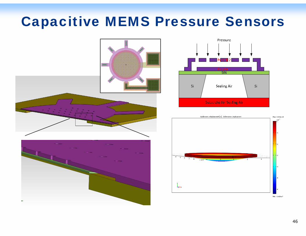
Capacitive MEMS Pressure Sensors
46
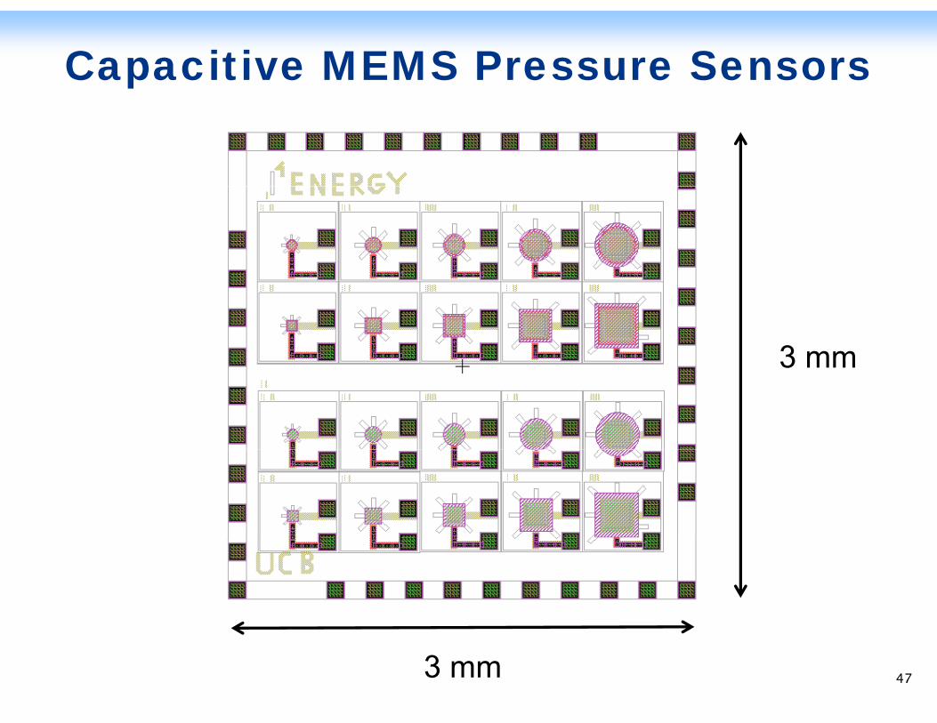
Capacitive MEMS Pressure Sensors
3 mm3 mm
3 mm 47
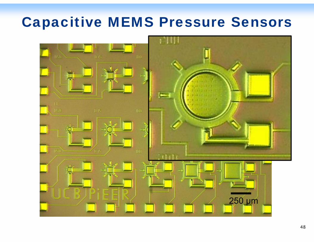
Capacitive MEMS Pressure Sensors
250 µm
48
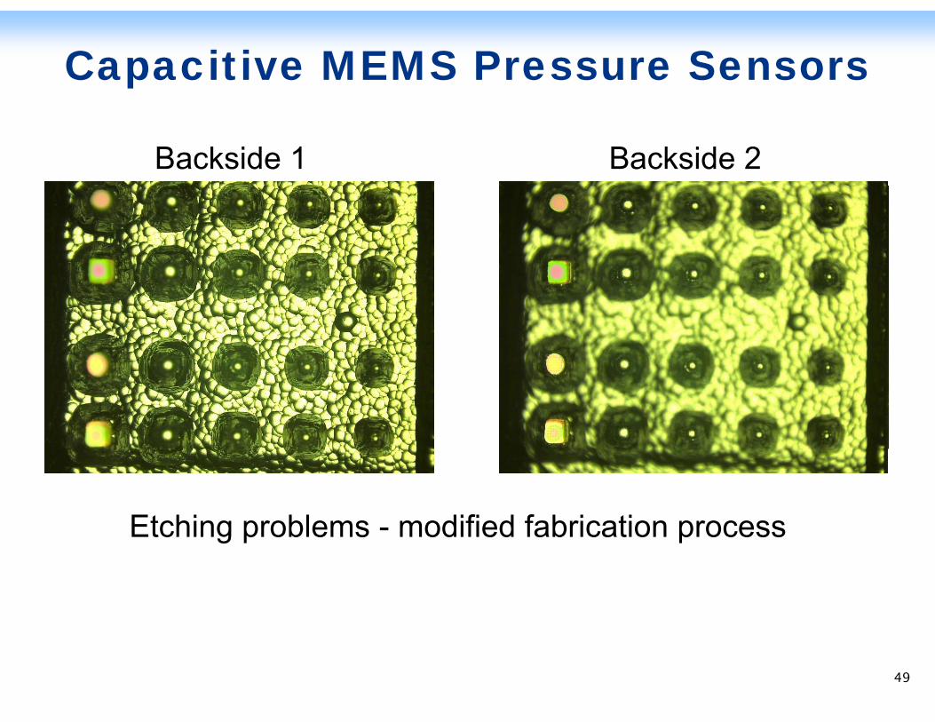
Capacitive MEMS Pressure Sensors
Backside 1 Backside 2
Etching problems - modified fabrication processEtching problems modified fabrication process
49
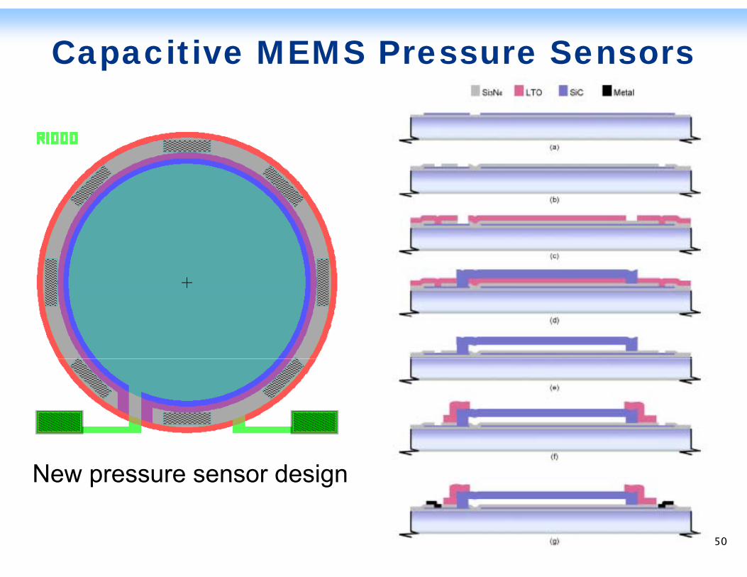
Capacitive MEMS Pressure Sensors
New pressure sensor design
50
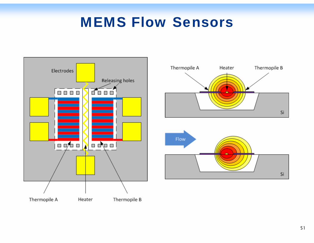
MEMS Flow Sensors
51
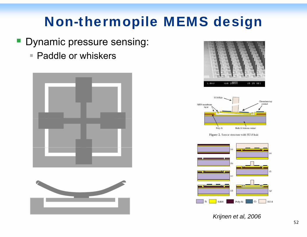
Non-thermopile MEMS designDynamic pressure sensing:
Paddle or whiskers
Krijnen et al, 200652
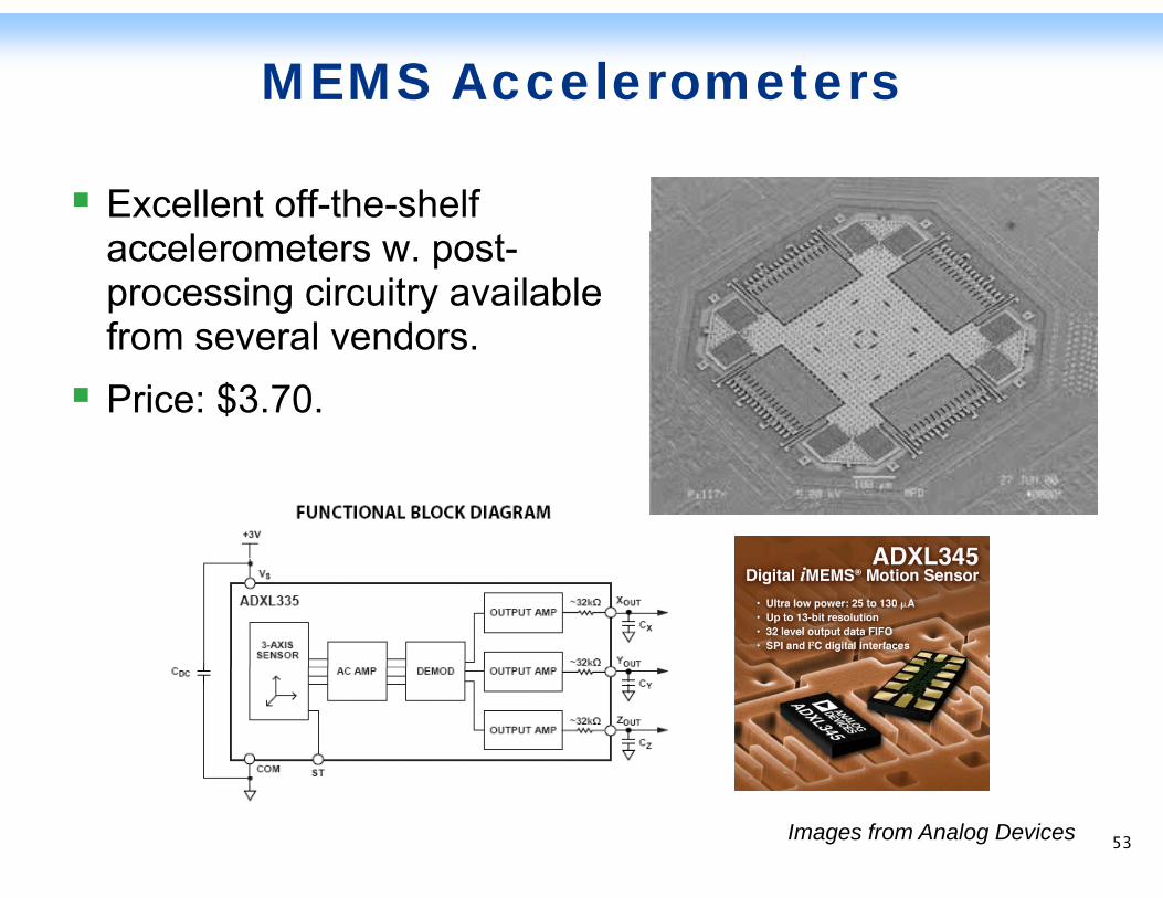
MEMS Accelerometers
Excellent off-the-shelf accelerometers w. post-processing circuitry available from several vendorsfrom several vendors.Price: $3.70.
Images from Analog Devices 53
MEMS Sensors - Next Steps
F b i t 2 d ti MEMSFabricate 2nd generation MEMS pressure sensorsMount and test in laboratory settingIntegrate with the wireless mesh networkIntegrate with the wireless mesh network
Fabricate flow sensorsMount and test in laboratory settingy gIntegrate with the wireless mesh network
Perform a limited pilot deployment and testing of the p p y gsensor packages in collaboration with the utilities.
Limited accelerated life-time testingSystem integration analysisSystem integration analysis
54
Low-power Wireless Mesh Network(System Integration)(System Integration)
55 55
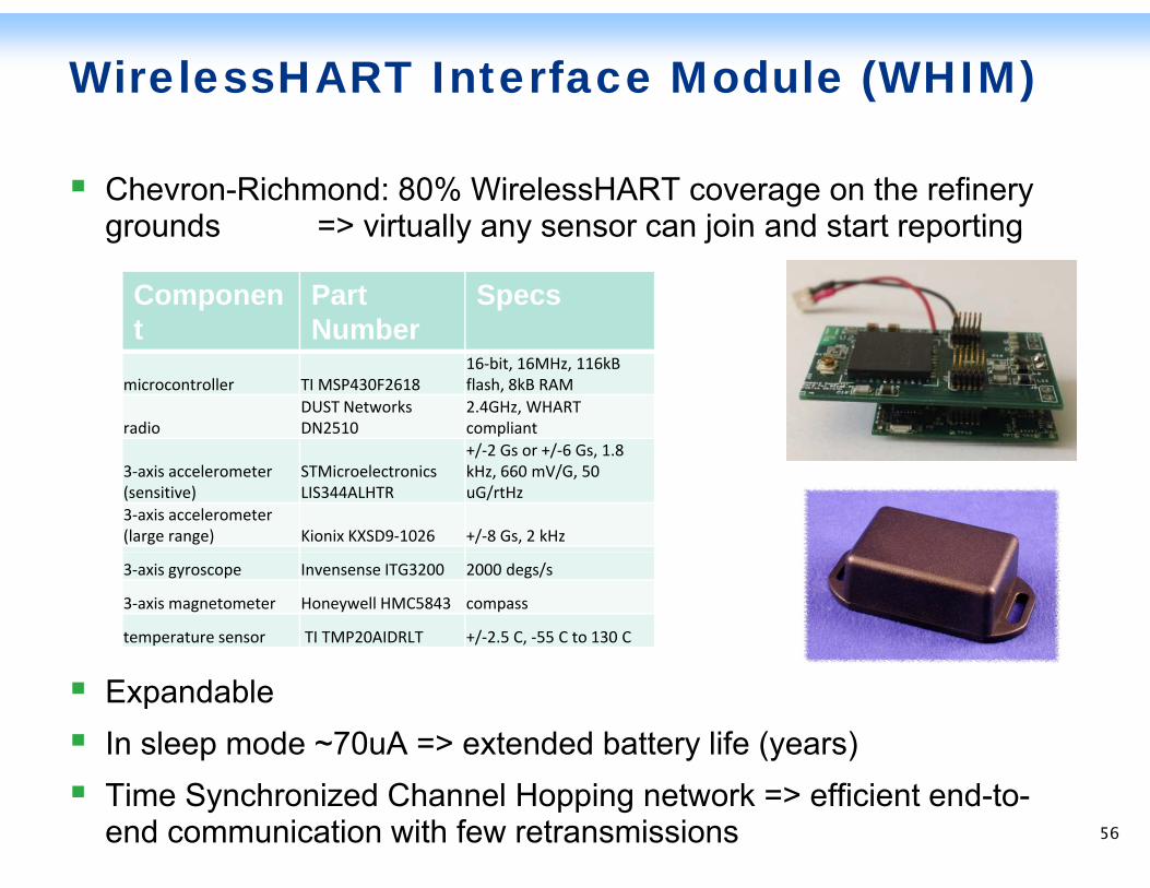
WirelessHART Interface Module (WHIM)
Chevron-Richmond: 80% WirelessHART coverage on the refinery grounds => virtually any sensor can join and start reportinggrounds => virtually any sensor can join and start reporting
Component
Part Number
Specst Number
microcontroller TI MSP430F261816‐bit, 16MHz, 116kB flash, 8kB RAM
radioDUST NetworksDN2510
2.4GHz, WHART compliant/ /
3‐axis accelerometer (sensitive)
STMicroelectronics LIS344ALHTR
+/‐2 Gs or +/‐6 Gs, 1.8 kHz, 660 mV/G, 50 uG/rtHz
3‐axis accelerometer (large range) Kionix KXSD9‐1026 +/‐8 Gs, 2 kHz
3‐axis gyroscope Invensense ITG3200 2000 degs/s
3‐axis magnetometer Honeywell HMC5843 compass
temperature sensor TI TMP20AIDRLT +/‐2.5 C, ‐55 C to 130 C
ExpandableIn sleep mode ~70uA => extended battery life (years)Time Synchronized Channel Hopping network => efficient end-to-end communication with few retransmissions 56
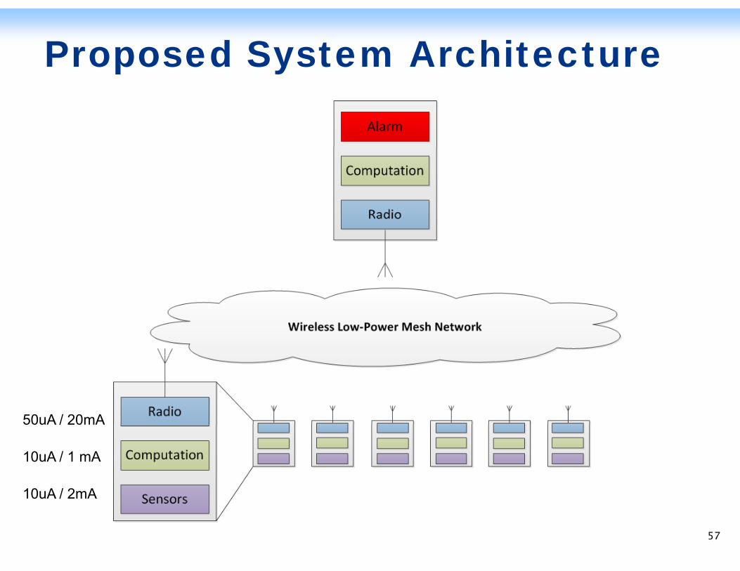
Proposed System Architecture
50uA / 20mA50uA / 20mA
10uA / 1 mA
10uA / 2mA10uA / 2mA
57
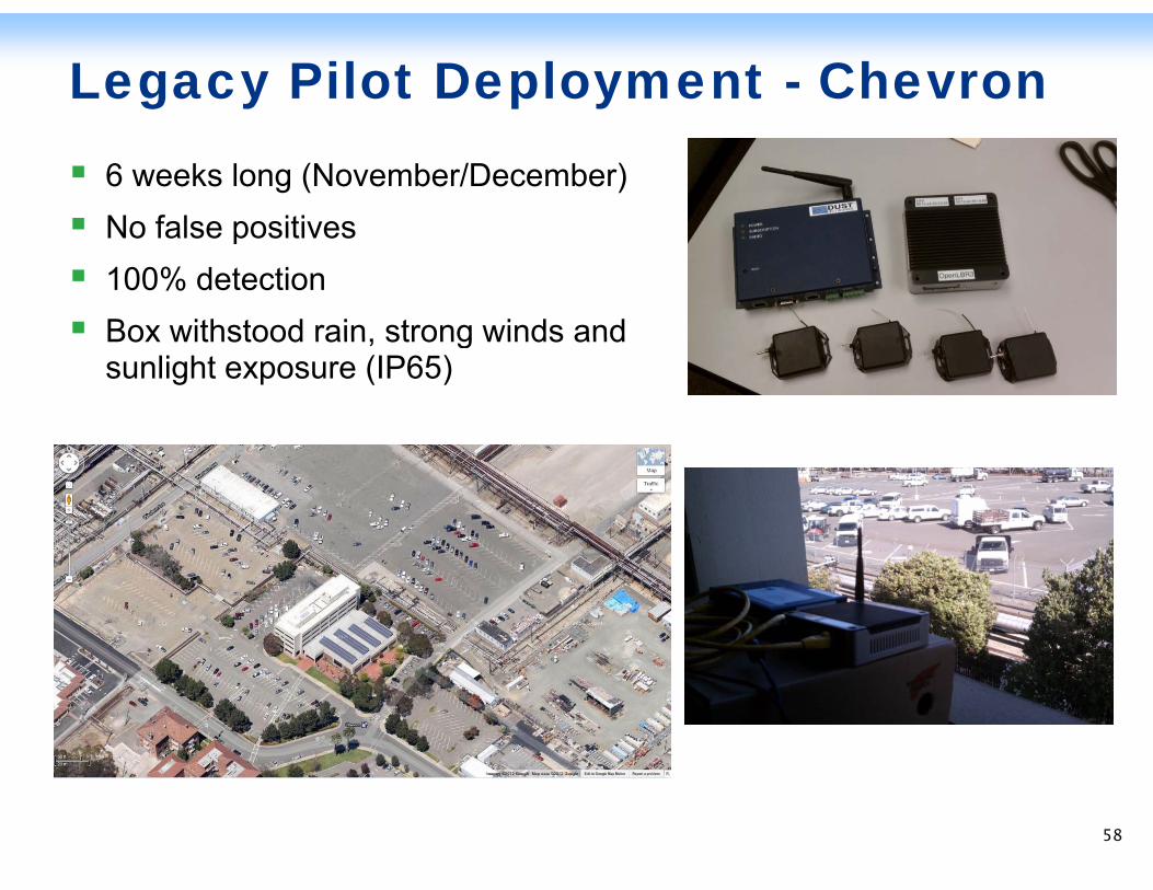
Legacy Pilot Deployment - Chevron6 weeks long (November/December)No false positivesNo false positives100% detectionBox withstood rain strong winds andBox withstood rain, strong winds andsunlight exposure (IP65)
58
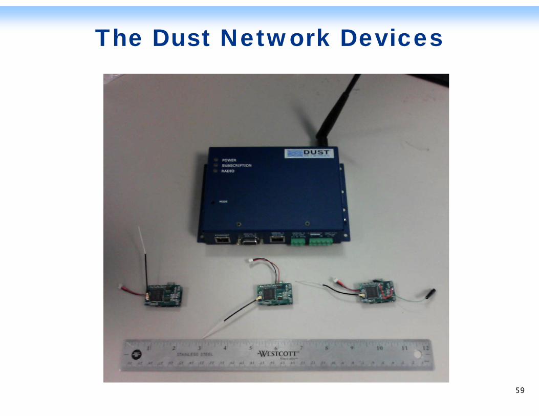
The Dust Network Devices
59
Ultrasonic Diagnostic and Test D i f N t l G Pi liDevices for Natural Gas Pipelines
60 60
Outline
Laser Ultrasonic Inspection Tools (welds, pipe offsets)Microfabricated Ultrasonic Flow SensorLab Sensor Test Set-UpLooking Forward – Next Steps
61
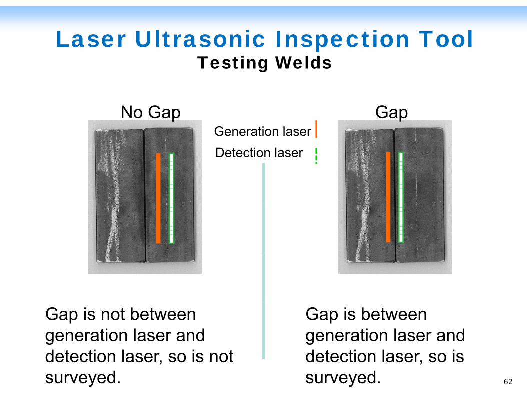
Laser Ultrasonic Inspection ToolTesting Welds
No Gap GapGeneration laserDetection laserDetection laser
Gap is not between generation laser and d t ti l i t
Gap is between generation laser and d t ti l idetection laser, so is not
surveyed.detection laser, so is surveyed. 62
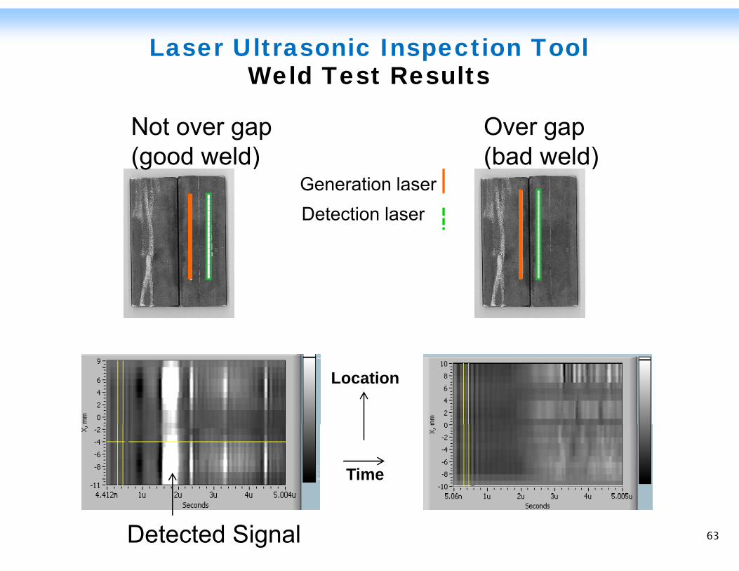
Laser Ultrasonic Inspection Tool Weld Test ResultsWeld Test Results
Not over gap( d ld)
Over gap(b d ld)(good weld) (bad weld)
Generation laserDetection laserDetection laser
Location
Time
Detected Signal 63
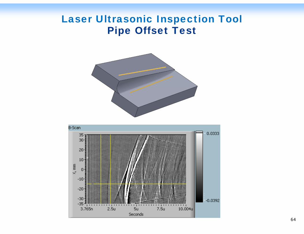
Laser Ultrasonic Inspection ToolPipe Offset TestPipe Offset Test
64
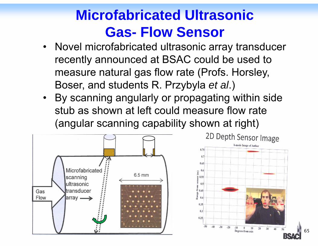
Microfabricated Ultrasonic Gas- Flow SensorGas- Flow Sensor
• Novel microfabricated ultrasonic array transducer recently announced at BSAC could be used to ymeasure natural gas flow rate (Profs. Horsley, Boser, and students R. Przybyla et al.)
• By scanning angularly or propagating within side stub as shown at left could measure flow rate (angular scanning capability shown at right)(angular scanning capability shown at right)
65 65
Microfabricated Ultrasonic Gas Flow Sensor (continued)( )
Features:• Single transducers, multi-element transducer arraysg , y• Sub-milliwatt transmitter drive power• Transmit range to few meters
P i lt i fl• Previous ultrasonic gas flow sensors were successful but large and power hungry (Lynnworth)
• Ultrasonic velocity in gases independent of pressure• Ultrasonic velocity in gases independent of pressure, virtually independent of humidity; temperature dependence few percent over 20 degree C range (in p p g g (air)
• Two companies in US provide ultrasonic flowmeterlib ti icalibration services
Plan:
66
Plan:Test in our lab flow sensor setup
66
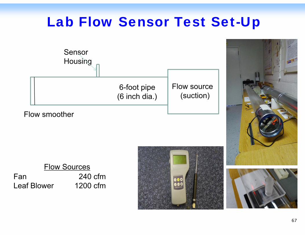
Lab Flow Sensor Test Set-Up
SensorHousing
Flow source 6-foot pipe
Housing
(suction)6 foot pipe (6 inch dia.)
Flow smoother
Flow SourcesF 240 fFan 240 cfmLeaf Blower 1200 cfm
67
Looking Forward Next StepsLooking Forward – Next Steps
1. Continue interaction with laser ultrasonic manufacturer and utility to evaluate compatibility
ith i ti i li lwith existing pipeline crawler
2. Complete analysis of ultrasonic flow sensor based on available prototype microfabricated scanning arrays
3. Test ultrasonic flow sensor in our lab air-flow tube setup
4. Design for incorporating ultrasonic flow sensor in operating gas pipe (test if possible)
68
p g g p p ( p )
68

Workshop will resume at 1:00 p
69
There is an upcoming $2M solicitation toThere is an upcoming $2M solicitation to demonstrate pipeline inspection and integrity management technologies. The following are the technologies that we see as most promising to enhance IMPs.Each of them will now be described in detailEach of them will now be described in detail.Your input will aid us in validating the benefits of the technology.the technology.We would like to prioritize the technologies to narrow the focus of the upcoming solicitation. If there are other beneficial technologies we have not presented, please let us know.
70
Methods to reduce operating costs andMethods to reduce operating costs and optimize field data collectionEnhanced operational awareness using lowEnhanced operational awareness using low cost/low power sensorsEnhanced IMPs through risk analysisEnhanced IMPs through risk analysis, prediction, and decision based methodologyIntegrating multiple crack inspection devicesIntegrating multiple crack inspection devices on a single pipeline crawlerInput from attendees on areas not presentedInput from attendees on areas not presented
71
Technologies capable of:Technologies capable of:◦ Addressing the issue of not knowing what’s where◦ Ensuring that when the field portion of the job is g j
completed the paperwork portion is also completed◦ Reducing manual data entry while not transferring
the burden to the back officethe burden to the back office◦ Reducing or eliminating data collection errors and
unknowns◦ The capability to integrate with other enterprise
systemsComments and Questions on this technologyComments and Questions on this technology area.
72
Methods should result in:Methods should result in:◦ Field Verification of the Advanced Metering
Infrastructure (AMI) two way communications andInfrastructure (AMI) two way communications and sensor capabilities◦ Optimal integration mix of AMI & non-AMI
communication technologies◦ Confirmation of full interoperability and security of
the AMI communications systemthe AMI communications systemProtection from vandalism and/or cyber attack
73
Methods should result in (cont ):Methods should result in (cont.):◦ Determination of the life cycle analysis of low cost,
low power sensors compared to existing technologylow power sensors compared to existing technology that requires retrofits to be compatible with the AMI◦ Interoperability of the low cost, low power sensors
under development◦ Redundant paths for data flow
I d it i f iti l t◦ Improved monitoring of critical parametersComments and Questions on this technology areaarea.
74
Th bj i i d l i l d d lThe objective is to develop, implement, and deploy tools and methodologies that will provide operators an enhanced working knowledge of their pipeline
l d l i isystems to supplement and complement existing IMPs.Tools and methodologies should focus on reducing
kg g
operator risk.Standards should provide guidance on individual threats, and methods threat interactions should be ,addressed. There is limited industry knowledge on the interactions of various threats and how they shouldinteractions of various threats and how they should influence the overall risk of a pipe segment.
75
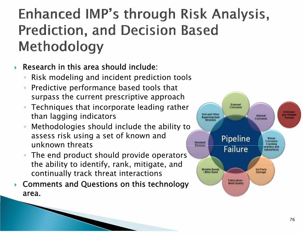
Research in this area should include:◦ Risk modeling and incident prediction tools◦ Predictive performance based tools that◦ Predictive performance based tools that
surpass the current prescriptive approach◦ Techniques that incorporate leading rather
than lagging indicatorsthan lagging indicators◦ Methodologies should include the ability to
assess risk using a set of known and unknown threatsunknown threats
◦ The end product should provide operators the ability to identify, rank, mitigate, and continually track threat interactionscontinually track threat interactions
Comments and Questions on this technology area.
76
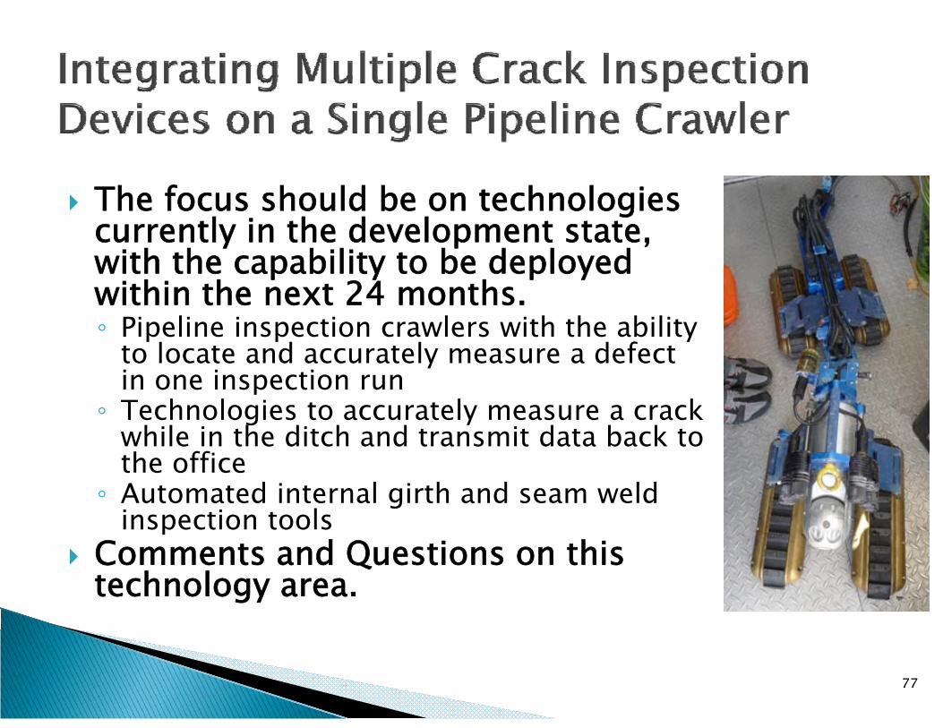
Th f h ld b h l iThe focus should be on technologies currently in the development state, with the capability to be deployed p y p ywithin the next 24 months.◦ Pipeline inspection crawlers with the ability
to locate and accurately measure a defect yin one inspection run
◦ Technologies to accurately measure a crack while in the ditch and transmit data back to h ffthe office
◦ Automated internal girth and seam weld inspection tools
C d Q i hiComments and Questions on this technology area.
77
Are there any technologies that wouldAre there any technologies that would provide significant benefits to IMPs and the safety of California’s natural gas pipelinessafety of California s natural gas pipelines that have not been mentioned?Of the technologies presented which haveOf the technologies presented, which have the highest priority?
78

We appreciate your participationWe appreciate your participationInput will be used to prepare a $2M competitive solicitation to demonstrate thecompetitive solicitation to demonstrate the discussed technologiesThe solicitation will be posted by the end ofThe solicitation will be posted by the end of 2012 and awards will be made in early 2013
79

Written comments and questions can be sent to:questions can be sent to:[email protected] and recording willPresentation and recording will be posted on the CEC website at: http://www.energy.ca.gov/research/notices/#08072012ot ces/ 080 0
80