naval postgraduate school - dtic.mil · washington headquarters services, ... table 4. ipt rf...
TRANSCRIPT

NAVAL
POSTGRADUATE SCHOOL
MONTEREY, CALIFORNIA
THESIS
Approved for public release; distribution is unlimited
ANALYSIS OF SATELLITE COMMUNICATION AS A METHOD TO MEET INFORMATION EXCHANGE
REQUIREMENTS FOR THE ENHANCED COMPANY CONCEPT
by
Matthew A. Senn James D. Turner
September 2008
Thesis Advisor: Alex Bordetsky Second Reader: William Welch

THIS PAGE INTENTIONALLY LEFT BLANK

i
REPORT DOCUMENTATION PAGE Form Approved OMB No. 0704-0188 Public reporting burden for this collection of information is estimated to average 1 hour per response, including the time for reviewing instruction, searching existing data sources, gathering and maintaining the data needed, and completing and reviewing the collection of information. Send comments regarding this burden estimate or any other aspect of this collection of information, including suggestions for reducing this burden, to Washington headquarters Services, Directorate for Information Operations and Reports, 1215 Jefferson Davis Highway, Suite 1204, Arlington, VA 22202-4302, and to the Office of Management and Budget, Paperwork Reduction Project (0704-0188) Washington DC 20503. 1. AGENCY USE ONLY (Leave blank)
2. REPORT DATE September 2008
3. REPORT TYPE AND DATES COVERED Master’s Thesis
4. TITLE AND SUBTITLE Analysis of Satellite Communications as a Method to Meet Information Exchange Requirements for the Enhanced Company Concept 6. AUTHOR(S) Matthew A. Senn, James D. Turner
5. FUNDING NUMBERS
7. PERFORMING ORGANIZATION NAME(S) AND ADDRESS(ES) Naval Postgraduate School Monterey, CA 93943-5000
8. PERFORMING ORGANIZATION REPORT NUMBER
9. SPONSORING /MONITORING AGENCY NAME(S) AND ADDRESS(ES) N/A
10. SPONSORING/MONITORING AGENCY REPORT NUMBER
11. SUPPLEMENTARY NOTES The views expressed in this thesis are those of the author and do not reflect the official policy or position of the Department of Defense or the U.S. Government. 12a. DISTRIBUTION / AVAILABILITY STATEMENT Approved for public release; distribution is unlimited
12b. DISTRIBUTION CODE
13. ABSTRACT (maximum 200 words) In the Global War on Terrorism and future irregular battlefields, the Marine Corps will not only fight in large-scale conventional war against sizable military forces but it will also engage adversaries that utilize smaller sized units dispersed asymmetrically over vast geographical locations. To address this emerging threat, the Marine Corps is developing the Enhanced Company (EC) concept, with the aim of providing the company commander with the tools necessary to make isolated decisions in an increasingly complex battlefield. In order to make timely, independent decisions and maintain information superiority these widely dispersed units will require organic access to services normally provided by higher headquarters. The Marine Corps Warfighting Laboratory is working to enhance the decision-making capabilities of the infantry company through the development of the Company Level Intelligence Center (CLIC) and the Company Level Operations Center (CLOC).
Current Marine Corps communications capabilities cannot meet the data demands of widely dispersed lower echelon units. The communications equipment organic to these units is mostly Line of Sight (LOS) technology. These systems limit the geographic dispersion of the units and are limited in data throughput capability. To allow for wider dispersion on the battlefield while providing the connectivity required for isolated decision making, these units require communications assets that are capable of operating Beyond the Line of Sight (BLOS) such as Satellite Communications (SATCOM) equipment. This thesis will seek to analyze the use of SATCOM in support of the Enhanced Company Concept in a FOB environment. Using a Limited Objective Experiment, the authors will test if SATCOM technology is sufficient to support Information Exchange Requirements (IERs) developed in the laboratory and validated with experience. Based on the outcome of the experiments the thesis will provide recommendations regarding the use of such technology.
15. NUMBER OF PAGES
87
14. SUBJECT TERMS Distributed Operations, SATCOM, BLOS, OTH, Communications, Information Exchange Requirements, Enhanced Company, CLOC
16. PRICE CODE
17. SECURITY CLASSIFICATION OF REPORT
Unclassified
18. SECURITY CLASSIFICATION OF THIS PAGE
Unclassified
19. SECURITY CLASSIFICATION OF ABSTRACT
Unclassified
20. LIMITATION OF ABSTRACT
UU NSN 7540-01-280-5500 Standard Form 298 (Rev. 8-98) Prescribed by ANSI Std. Z39.18

ii
THIS PAGE INTENTIONALLY LEFT BLANK

iii
Approved for public release; distribution is unlimited
ANALYSIS OF SATELLITE COMMUNICATIONS AS A METHOD TO MEET INFORMATION EXCHANGE REQUIREMENTS FOR THE ENHANCED COMPANY
CONCEPT
Matthew A. Senn Major, United States Marine Corps
B.S., United States Naval Academy, 1995
Submitted in partial fulfillment of the requirements for the degrees of
MASTER OF SCIENCE IN SPACE SYSTEMS OPERATIONS
and MASTER OF SCIENCE IN INFORMATION SYSTEMS OPERATIONS
James D. Turner
Major, United States Marine Corps B.S., University of Florida, 1998
Submitted in partial fulfillment of the
requirements for the degree of
MASTER OF SCIENCE IN SPACE SYSTEMS OPERATIONS
from the
NAVAL POSTGRADUATE SCHOOL September 2008
Authors: Matthew A. Senn James D. Turner
Approved by: Alex Bordetsky
Thesis Advisor
William Welch Second Reader
Rudy Panholzer Chairman, Space Systems Academic Group Dan Boger Chairman, Department of Information Sciences

iv
THIS PAGE INTENTIONALLY LEFT BLANK

v
ABSTRACT
In the Global War on Terrorism and future irregular battlefields, the Marine Corps
will not only fight in large-scale conventional war against sizable military forces but it
will also engage adversaries that utilize smaller sized units dispersed asymmetrically over
vast geographical locations. To address this emerging threat, the Marine Corps is
developing the Enhanced Company (EC) concept, with the aim of providing the company
commander with the tools necessary to make isolated decisions in an increasingly
complex battlefield. In order to make timely, independent decisions and maintain
information superiority these widely dispersed units will require organic access to
services normally provided by higher headquarters. The Marine Corps Warfighting
Laboratory is working to enhance the decision-making capabilities of the infantry
company through the development of the Company Level Intelligence Center (CLIC) and
the Company Level Operations Center (CLOC).
Current Marine Corps communications capabilities cannot meet the data demands
of widely dispersed lower echelon units. The communications equipment organic to
these units is mostly Line of Sight (LOS) technology. These systems limit the
geographic dispersion of the units and are limited in data throughput capability. To allow
for wider dispersion on the battlefield while providing the connectivity required for
isolated decision making, these units require communications assets that are capable of
operating Beyond the Line of Sight (BLOS) such as Satellite Communications
(SATCOM) equipment.
This thesis will seek to analyze the use of SATCOM in support of the Enhanced
Company Concept in a FOB environment. Using a Limited Objective Experiment, the
authors will test if SATCOM technology is sufficient to support Information Exchange
Requirements (IERs) developed in the laboratory and validated with experience. Based
on the outcome of the experiments the thesis will provide recommendations regarding the
use of such technology.

vi
THIS PAGE INTENTIONALLY LEFT BLANK

vii
TABLE OF CONTENTS
I. INTRODUCTION........................................................................................................1 A. BACKGROUND ..............................................................................................1 B. OBJECTIVES ..................................................................................................3 C. RESEARCH QUESTIONS.............................................................................4 D. SCOPE, LIMITATIONS, AND ASSUMPTIONS ........................................4 E. METHODOLOGY ..........................................................................................5 F. ORGANIZATION OF THESIS .....................................................................5
II. ANALYSIS OF INFORMATION EXCHANGE REQUIREMENTS....................7 A. OVERVIEW OF INFORMATION EXCHANGE REQUIREMENTS .....7
1. Background of Naval Research Laboratory Report for MCWL Experiment ...........................................................................................7 a. Purpose of Report......................................................................7 b. Company Critical Tasks............................................................8
2. Information Exchanges Where Company is a Node.........................9 B. INTERVIEW SUMMARY ...........................................................................11
1. Recent Combat History of 1st Battalion, 7th Marines ...................11 2. Warfighter Feedback.........................................................................12
III. FIELD EXPERIMENTATION ................................................................................15 A. EXPERIMENTATION METHODOLGY ..................................................15
1. Experiment Scenario .........................................................................16 2. Experiment Specifics .........................................................................16
a. Network (Physical) Configuration .........................................17 b. Information Exchanges and Application Configuration ......19 c. Experiment Metrics.................................................................39 d. Experiment Scripts..................................................................40 e. Impact of Concurrent Experiment .........................................43
B. EXPERIMENT UTILITY.............................................................................44
IV. RESULTS ...................................................................................................................47 A. ANALYSIS OF DATA ..................................................................................47 B. COMPARISON OF TESTED SCRIPTS TO SOFTWARE IN
MCTOG CLOC CONCEPT APPLICATIONS..........................................51
V. CONCLUSION AND RECOMMENDATIONS.....................................................53 A. WHAT WAS LEARNED ..............................................................................53 B. SATCOM TERMINAL RECOMMENDATION .......................................53
1. Proof of Concept ................................................................................53 2. Higher Order Impacts .......................................................................54
C. BANDWIDTH MANAGEMENT.................................................................55 1. Re-examine “Network Centric Warfare” Specifics ........................55 2. Improved Use of Bandwidth .............................................................56
D. DEFINING BANDWIDTH REQUIREMENTS .........................................56

viii
1. Capability Based Acquisition across the MAGTF..........................57 E. THE FINAL WORD......................................................................................58
APPENDIX A. SWE-DISH IPT TECHNICAL SPECIFICATIONS ..............................59
APPENDIX B. IX CHARIOT® TECHNICAL SPECIFICATIONS ...............................65 A. ABOUT IX CHARIOT®................................................................................65 B. BASIC SETUP ...............................................................................................65
LIST OF REFERENCES......................................................................................................67
INITIAL DISTRIBUTION LIST .........................................................................................69

ix
LIST OF FIGURES
Figure 1. MCWL Concept Network Architecture...........................................................17 Figure 2. LOE Network Architecture..............................................................................18 Figure 3. Portion of screen shot from NetMeeting test ...................................................50 Figure 4. IX Chariot® Basic Setup .................................................................................66

x
THIS PAGE INTENTIONALLY LEFT BLANK

xi
LIST OF TABLES
Table 1. Summary List of IERs in which Company is a Node......................................10 Table 2. Summary of LOE Data ....................................................................................49 Table 3. Comparison of IX Chariot® Script to MCTOG Software Applications .........51 Table 4. IPT RF Characteristics.....................................................................................59 Table 5. IPT General Characteristics .............................................................................61 Table 6. Power Supply Unit Parameter..........................................................................61 Table 7. Block Up Converter Parameters ......................................................................62 Table 8. Internal i-Direct Modem Parameters ...............................................................62 Table 9. Solid State Power Amplifier Parameters .........................................................62 Table 10. Low Noise Block Down converter Parameters................................................63

xii
THIS PAGE INTENTIONALLY LEFT BLANK

xiii
ACRONYMS AND ABBREVIATIONS
AES Advanced Encryption Standard AO Area of Operations AOR Area of Responsibility ASAS-L All Source Analysis System-Light BAT Biometric Automated Toolset BFT Blue Force Tracker BLOS Beyond Line of Sight C&S Command and Staff C2ID Command and Control Integration Division C2PC Command and Control Personal Computer C2 Command and Control CAPESET Capability Set CASEVAC Casualty Evacuation CASREP Casualty Report CENETIX Center for Network Innovation and Experimentation CLOC Company Level Operations Center CLIC Company Level Intelligence Center COC Combat Operations Center CONOPS Concept of Operations CONUS Continental United States DAFIF Digital Aeronautical Flight Informational File DISA Defense Information Systems Agency DISN Defense Information Systems Network DO Distributed Operations EC Enhanced Company ECPs Entry Control Points EMT Effects Management Tool EPLRS Enhanced Position Location Reporting System EWS Expeditionary Warfare School FBCB2 Force Battle Control, Brigade and Below FDC Fire Direction Center FOB Forward Operating Base GCE Ground Combat Element GEO Geostationary GPS Global Positioning System HIIDE Hand-held Interagency Identity Detection Equipment HQMC Headquarters Marine Corps HSI Human-Systems Integration IAS Intelligence Analysis System ICMP Internet Control Message Protocol ID Identification IERs Information Exchange Requirements

xiv
IP Internet Protocol IPL Imagery Product Library IOS Intelligence Operations Server ISR Intelligence, Surveillance and Reconnaissance IOWs Intelligence Operations Workstations Kbps Kilobits per second LAN Local Area Network LOE Limited Objective Experiment LOS Line of Sight MAGTF Marine Air-Ground Task Force MEF Marine Expeditionary Force Mbps Megabits per second MCCDC Marine Corps Combat Development Command MCSC Marine Corps Systems Command MCTOG Marine Corps Tactics and Operations Group MCTSSA Marine Corps Tactical Systems Support Activity MCWL Marine Corps Warfighting Lab MIDB Modernized Integrated Database MSC Main Support Component MSR Main Supply Route NPS Naval Postgraduate School NRL Naval Research Laboratory OEF Operation Enduring Freedom OIF Operation Iraqi Freedom OPTEMPO Operational Tempo OTH Over The Horizon P2P Point-to-Point RF Radio Frequency RFI Request for Information SATCOM Satellite Communications SITREP Situation Report SNMP Simple Network Management Protocol SOF Special Operations Forces SOP Standard Operating Procedures TCP Transmission Control Protocol T/E Table of Equipment T/O Table of Organization TTPs Tactics, Techniques and Procedures UAV Unmanned Aerial Vehicle UDP User Datagram Protocol UUNS Urgent Universal Needs Statements VMF Variable Message Format VTC Video Teleconference WAN Wide Area Network

xv
ACKNOWLEDGMENTS
The authors would like to thank the following individuals: For their guidance and insight: Dr. Bordetsky, NPS Mr. Welch, NPS LtCol Oros, NPS For the technical support and on the job training: Donovan Dinger, Swe-Dish Michael Clement, NPS CENETIX Lab Maj Cornell, MCTSSA Eric Gay, MCTSSA For their theoretical input, support and discussion: Maj Browne, MCWL The Officers of 1/7, 29 Palms LtCol Buzby, MCTOG And of course, our families for their consistent and unflagging support during all of our Marine Corps career endeavors.

xvi
THIS PAGE INTENTIONALLY LEFT BLANK

1
I. INTRODUCTION
A. BACKGROUND
Traditionally, the Marine Corps brings Defense Information Systems Network
(DISN) services into a theater via satellite terminals located at Marine Expeditionary
Force (MEF) and Major Subordinate Command (MSC) headquarters. Various terrestrial
based transmission terminals then distribute these services to the subordinate Marine
forces in the Area of Responsibility (AOR). Lower echelon units tend to use low
bandwidth terrestrial systems for reach back to higher headquarters. Since the Gulf War,
bandwidth requirements have grown exponentially at all levels of organization, including
at lower echelon units such as infantry battalions and companies; the Defense
Information Systems Agency (DISA) claims that at the peak of Operation Iraqi Freedom
“3 Gbps of satellite bandwidth was being provided to the theater . . . 30 times the
bandwidth made available during [Desert Storm].”1 Current urban and asymmetric
operations in Iraq and Afghanistan have served to further increase the demand for
bandwidth. In order to meet this increase in demand, the Marines have distributed
terminals designed to handle large traffic loads as well as satellite communications
services, typically organic equipment at the regiment or higher echelons, as far down as
battalion-sized units. Marine Corps units identifying a capability gap in communications
at the lower echelons have submitted numerous Urgent Universal Needs Statements
(UUNSs) to expedite a solution to the problem. Efforts are currently underway at
Headquarters Marine Corps (HQMC), Marine Corps Combat Development Command
(MCCDC), and Marine Corps Systems Command (MCSC) to research and procure
solutions to meet the bandwidth shortfall for battalion-sized units and below operating
using current tactics, techniques and procedures.
Since 1963, when MCO 3120.3, formalized the Marine Air-Ground Task Force
(MAGTF) the Corps has structured its forces using a scalable and balanced air-ground,
1 Leland Joe and Isaac Porche III, Future Army Bandwidth and Capabilities (Santa Monica, CA: Rand
Corporation, 2004).
2
combined arms task organization.2 This modular breakdown into ground, air, and
support elements has provided great utility in organizing and deploying appropriately
sized forces for conventional conflicts throughout history. Based on lessons learned from
past and current conflicts and a forecast increase in the number of future asymmetric
battlefields, the Marine Corps is developing concepts to fight an elusive adversary who
utilizes small, vastly distributed units to engage in localized yet very violent actions and
who makes every attempt to avoid a conventional massed force on force battle. The
Marine Corps describes these types of threats as “hybrid challenges”3; challenges that
will require new ways of deploying and better trained and equipped small unit leaders.
As part of the effort to expand abilities to operate in a more dispersed environment the
Marine Corps is developing a concept labeled Enhanced Companies (EC). This new
concept focuses on company size and below units dispersed in urban terrain or at such
distances that limit conventional support capability of higher or adjacent units. These
units will rely, more than ever, on the spirit of commander’s intent and increased
autonomous decision support capability to execute key, isolated actions that may have
strategic impact. To make informed and timely decisions, these dispersed forces will
require the capability to organically gather and process information typically passed from
higher. These units will not be able to count on the already overtaxed, smaller
bandwidth, and distance/terrain limited information exchange technologies that exist on
today’s battlefield to provide that data.
Special-operations Forces (SOF) unit deployments are autonomous in nature and
are inherently able to respond to both symmetric and asymmetric threats. Most SOF
units deploy at great distances from adjacent and higher units. Those units are often
called “disadvantaged users” in part due to the complex terrain they deploy to, their
requirement for mobility as well as their limited capability to haul or power large pieces
of communications equipment. However, SOF units are still able to execute their
mission effectively because they are equipped with technology that adequately supports
2 Edwin H. Simmons. The United States Marines: A History, Fourth Edition (Annapolis, Maryland:
Naval Institute Press, 2003). 3USMC, USMC Vision & Strategy 2025, http://www.marines.mil/units/
hqmc/cmc/Documents/MCVS2025%2030%20June.pdf (accessed 17 September 2008).

3
their information exchange requirements. SOF and dispersed USMC units will never
execute the same mission set, however, the manner in which each type of unit deploys to
execute its particular mission and the inherent communications requirements an
Enhanced Company and its platoons will encounter are comparable. Both types of units
may be operated beyond the range of normally deployed equipment or in environments
where that equipment may not be effective and therefore must substitute alternate
technology for traditional methods of communication. SOF has successfully translated
this dispersed type deployment directly into requirements documents to procure
SATCOM equipment that provides the necessary links and bandwidths. The success
SOF have enjoyed as a “disadvantaged user” may serve as a model for capabilities in
support of Enhanced Companies, if not an initial vector for Marine Corps planners.
This thesis will analyze the utility of satellite communications in support of the
Enhanced Company concept by validating forecast information exchange requirements
for a dispersed Marine infantry company and then conducting a Limited Objective
Experiment (LOE) using SATCOM technology to measure the effectiveness with which
the technology meets the validated Information Exchange Requirements (IERs). It will
attempt to determine the best location for satellite terminals within the MAGTF structure
at units higher, lower and adjacent to the infantry company. The thesis will also suggest
which capabilities these terminals should have in order to meet the IERs of these units
based on these experiments.
B. OBJECTIVES
The primary objective of this research is to determine if the use of SATCOM is a
viable solution as an information exchange technology for use in the USMC Enhanced
Company concept of deployment.
A secondary objective includes the validation of proposed USMC EC IERs
through interviews with USMC infantry units with recent combat deployment experience
in order to help determine which IERs and decision-making applications the dispersed
unit will actually use. This objective helps lead the way towards establishing Standard

4
Operating Procedures (SOPs) and Tactics, Techniques and Procedures (TTPs) that future
communication network architects can use to define capability sets for technology to
meet those requirements.
The subject of this thesis is extremely narrow; as compared to the intricacies
involved in developing an entire architecture that supports the EC concept. However,
this work will not only provide a possible answer for future communication architects but
will also serve as a starting point for developing joint information exchange technologies
that will enable future network-centric warfare concepts.
C. RESEARCH QUESTIONS
The primary research question of this thesis seeks to determine if the IERs
developed by the Naval Research Laboratory for the Marine Corps Warfighting
Laboratory are valid and if so, the authors will seek to determine whether a particular
SATCOM technology is satisfactory for information exchange by an Enhanced
Company. Given a list of requirements and technologies, the authors will provide a
recommendation as to the appropriate echelon in the Ground Combat Element (GCE) of
the MAGTF for deployment of those technologies.
D. SCOPE, LIMITATIONS, AND ASSUMPTIONS
The scope of this thesis will include:
The analysis of information exchange requirements associated with the Marine
Corps Enhanced Company to include those exchange requirements essential for
Intelligence, Maneuver, Logistics, Command and Control (C2), and Fire Support.
The analysis of a current SATCOM technology to determine if it can support the
information exchange requirements mentioned above.
Field experiments at the Marine Corps Tactical Systems Support Activity
(MCTSSA), located at Camp Pendleton, California.
Face to face interviews conducted with a combat experienced infantry battalion /
company currently undergoing pre-deployment training.

5
E. METHODOLOGY
In July of 2006, the Warfighter Human Systems Integration Laboratory at the
U.S. Naval Research Laboratory (NRL) in Washington D.C. provided an assessment to
the Marine Corps Warfighting Laboratory (MCWL) regarding a proposed optimal mix of
devices for infantry companies and below operating in a Distributed Operations mode.4
As part of the assessment, the NRL developed an information exchange list for each
included node. The main objective of this thesis is to validate the list provided in the
assessment by interviewing Communications, Intelligence and Operations Officers from
Marine infantry units that have deployed in support of current contingencies around the
world. The experiences of units that have deployed in real-world environments and in a
manner similar to those conceptualized by the Marine Corps Tactics and Operations
Group (MCTOG) for the Enhanced Company will provide a check to the laboratory
developed IERs and perhaps serve as a basis for doctrinal information exchange
requirements for EC deployments.
The authors will conduct field experimentation using a single current commercial
technology with metrics designed to evaluate the utility of SATCOM to meet information
exchange requirements in an Enhanced Company environment. Equipment performance
will be measured to determine if that particular technology will have adequate bandwidth,
be useable by those that will be utilizing the technology to communicate, and will meet
the portability requirements consistent with widely dispersed and mobile units.
F. ORGANIZATION OF THESIS
This paper is divided into fivechapters as follows:
Chapter I consists of the Introduction, which provides a general overview of the
background, purpose and methodologies associated with this research.
Chapter II will cover the currently published EC IERs, according to MCWL, and
will vet that list by using input garnered from interviews with combat unit leadership.
4 Coyne, et al., Final Report: Company and Below Command and Control Information Exchange
Study (Washington D.C.: Naval Research Laboratory, 2006).

6
Chapter III contains information regarding the Limited Objective Experiments
conducted in support of the thesis.
Chapter IV consists of an analysis of the data generated in the experiment
outlined in Chapter III as well as the utility of that experiment.
Chapter V will provide conclusions regarding the findings of this thesis. It will
also provide recommendations as to the feasibility of using SATCOM in the Enhanced
Company Level Operations Center as well as recommendations regarding for further
research and actions that will further support the objectives of this thesis.

7
II. ANALYSIS OF INFORMATION EXCHANGE REQUIREMENTS
A. OVERVIEW OF INFORMATION EXCHANGE REQUIREMENTS
The following sections explain the method used to generate a list IERs in support
of the Limited Objective Experiment explained later in the thesis.
1. Background of Naval Research Laboratory Report for MCWL Experiment
a. Purpose of Report
In 2006, the MCWL Technology Division tasked the Human-Systems
Integration (HSI) Laboratory, part of the NRL, with providing a human factors-based
assessment of the optimal mix of communications modalities and technology at each
communication node (point where information flows into and out of)5. The goal of the
MCWL study was to identify the optimal set of communication modalities and gear for
Distributed Operations (DO) equipped units. When first developed, the DO concept of
deployment sought to permit small units to operate at distances beyond support from
adjacent and higher command elements. In this regard, MCWL identified the primary
technical limitation preventing traditionally deployed Marine units from adopting the DO
mode is the range of their communications gear and the increase in communications
burden that DO places on the small unit leaders. The Distributed Operations moniker
used for the concepts being researched in 2006 has recently given way to similar concepts
with different names.
The final report includes a DO communications task analysis, the
information exchange list per node and the list of modes per exchange. For the purposes
of this thesis, the authors will focus on the list of information exchanges
5 Coyne, et al., Final Report: Company and Below Command and Control Information Exchange
Study (Washington D.C.: Naval Research Laboratory, 2006).

8
where the company is a node and use that list as an experimental baseline for IERs for an
Enhanced Company, operating in a Forward Operating Base (FOB) environment.
The content of the information exchange list and task analysis detail the
common or significant communications likely to occur within an infantry company. The
specific chains of communication detailed in this list are based upon an understanding of
the likely concept of operations (CONOPS) for a company, or elements of a company
operation in a DO mode, acquired through discussions and exchanges with other MCWL
staff who were directly responsible for the experimentation and development of the DO
concept.6 Although not specifically developed as a comprehensive list for an Enhanced
Company in a FOB environment this list is adequate as a starting point for developing a
list of IERs. However, based on the fact that the list was developed in a laboratory
environment, the IERs included need to be validated with real world experience to define
what capabilities an Enhanced Company will rely on to complete its mission. The task
analysis was organized by critical functions, with the primary function areas being
Intelligence, Maneuver, Fire Support, Command and Control, and Logistics.
b. Company Critical Tasks
The purpose of any information exchange is to help rapidly and decisively
execute critical tasks. The following is a list of those tasks deemed critical to mission
success by the NRL report.7
Intelligence: 1) Collect Information 2) Disseminate Intelligence Maneuver: 3) Conduct Tactical Movement 4) Engage Enemy with Direct Fire and Maneuver Fire Support: 5) Employ Mortars 6) Employ Close Air Support 7) Employ Field Artillery
6 Coyne, et al., Final Report: Company and Below Command and Control Information Exchange
Study (Washington D.C.: Naval Research Laboratory, 2006). 7 Ibid.

9
8) Employ Naval Gunfire 9) Coordinate, Synchronize and Integrate Fire Support Command and Control: 10) Plan for Combat Operations 11) Direct and Lead Unit during Preparation for the Battle 12) Direct and Lead Units in Execution of Battle Logistics: 13) Handle Combat Support Issues (e.g., casualties, supply, POWs)
2. Information Exchanges Where Company is a Node
Table 1 gives a brief synopsis of the specific IERs generated by the NRL in which
the Company Combat Operations Center (COC) is expected to be a node.8 The
exchanges can occur either up to the battalion, down to the platoon commander or to
adjacent or supporting units. A detailed description of each information exchange and
the HSI Laboratory suggested method and means of dissemination is provided in Chapter
III, Paragraph A.2.b; Experiment Specifics.
The officer leadership of the 1st Battalion, 7th Marine Regiment, stationed aboard
MCB Twenty-nine Palms, California, were interviewed in person and provided the list of
IERs in Table 1. Those officers, including the Battalion Commanding Officer,
Operations Officer, Assistant Operations Officer, Alpha Company Commander and the
Intelligence Officer were asked to validate the list by indicating whether or not the traffic
would actually be sent, how often the traffic would be sent, and if the HSI laboratory’s
suggested method and means of dissemination was valid.
8 Coyne, et al., Final Report: Company and Below Command and Control Information Exchange
Study, (Washington D.C.: Naval Research Laboratory, 2006).

10
INE# IER # SHORT TITLE GOAL
1 1.2.1 Situation Report (SITREP) Pass important information through the chain of command
2 1.2.2 Report Enemy Activity Report enemy sighting and movement up the chain of command
3 1.5 Urgent Unformatted Provide information on current situation which requires immediate action
4 1.6 Routine Unformatted Provide information which may not require immediate action
5 2.2 Distribute Intel. to lower Pass relevant intelligence down the chain of command
6 2.4 Request for Information (RFI) Pass on intelligence need
7 2.5 Request for Intel. The Platoon Commander or above requests specific intelligence from Battalion
8 3.1 Issue FRAGGO Provide fragment of Operation Order with Commander's intent to lower levels
9 3.2 Position Report at Check Point Provide confirmation of arrival at designated area or next checkpoint
10 6.2 Call for Fire (Artillery) Request for fire support from the Artillery Fire Direction Center (FDC)
11 6.3 Message to Observer (Artillery) Provide observer with basic information regarding artillery support
12 6.4 Shot / Splash Calls (Artillery) Round is released on target based on call for fire
13 6.5 Adjust Fire (Artillery) Redirect artillery fire so it is on target
14 6.6 Report Effects (Artillery) Inform Fire Direction Center (FDC) of effect on the target
15 7.2 Request Air from FSCC Request to Fire Support Coordination Center for air asset support
16 7.4 9-Line Brief (Close Air Support) Air asset and observer coordinate attack to neutralize target
17 7.5 Check-in (Close Air Support) The observer makes visual contact with the air asset and confirms the target
18 7.6 BDA (Close Air Support) Report Battle Damage Assessment of attack on target
19 8.1 Call for Fire (NSFS) Round is release on target based on call for fire.
20 8.2 MTO (NSFS) Provide observer with basic information regarding NSFS support
21 8.3 Shot / Splash Calls (NSFS) Round is released on target based on call for fire
22 8.4 Adjust Fire (NSFS) Redirect NSFS fire so it is on target
23 8.5 Report Effects (NSFS) Inform Fire Direction Center (FDC) of effect on the target
24 10.1 Issue WARNO A Warning Order is issued to allow a unit to prepare for an upcoming order
25 11.1 Bn Issues OPORD Company Commander receives the Operation Order from the Battalion
26 13.1.2 Supply Request from CSS Unit Acquire supplies from the Battalion's Combat Service Support Unit
27 13.2.1 Casualty Report (CASREP) Inform higher of wounded members
28 13.2.2 Casualty Evacuation (CASEVAC) Request Have a serious casualty moved from the battlefield for immediate care
29 13.2.3 Bn Responds to CASEVAC Provide information to the CASEVAC requester on how evacuation will occur
30 13.2.4 CASEVAC Asset Responds Inform small unit leader of inbound CASEVAC unit and coordinate pick up Table 1. Summary List of IERs in which Company is a Node

11
B. INTERVIEW SUMMARY
1. Recent Combat History of 1st Battalion, 7th Marines
First Battalion, 7th Marines first deployed to Iraq in March of 2003. The Battalion
saw significant combat action in its movement towards Baghdad and in the streets of the
Iraqi capital. In April, the Battalion turned over control of their sector to the US Army
and took up positions in the city of An Najaf. The battalion redeployed to Twenty-nine
Palms, CA in October 2003. In August 2004, the battalion deployed to Western Iraq in
support of Operation Iraqi Freedom II. There the battalion conducted security operations
in the cities and roadways along the Euphrates River and Syrian border to include
Husaybah, Karabilah, Sadah, Ubaydi, Al Qa'im, Haditha, Hit and Haqlania. Involved in
combat operations on a daily basis, the battalion conducted mounted and dismounted
urban patrols, cordon knocks, Main Supply Route (MSR) security, sweep operations, and
border security in the battalion’s Area of Operation (AO). From February through
September 2006, 1st Battalion, 7th Marines deployed to the Al Qa’im Region in Western
Iraq. The battalion occupied fifteen platoon and company battle positions, which
controlled over 5,000 square miles in the Western Euphrates River Valley. Each platoon,
paired with an Iraqi Army platoon and members of the local constabulary, yielded
tremendous impact on security throughout the Al Qa’im region and in so doing, created
the model for Dispersed Operations throughout the Iraq Theater. 9
In addition to the Battalion’s extensive combat experience and familiarity with
dispersed operations, all of the officers interviewed in Twenty-nine Palms also had
combat experience either in Iraq during OPERATION IRAQI FREEDOM (OIF) or
Afghanistan during OPERATION ENDURING FREEDOM (OEF). Of note, the
Battalion’s current operations officer, Capt Jeremiah Salame, a company commander
during the 2006 deployment, operated from a Forward Operating Base in which his
9 “1/7 History,” 1st Battalion, 7th Marines, http://www.i-mef.usmc.mil/div/7mar/1bn/history.asp
(accessed August 20, 2008).

12
company was located at distances that served to isolate the company from higher
headquarters and the ease at which that headquarters provided traditional support.10
2. Warfighter Feedback
First Battalion, 7th Marines is currently in an intensive training phase to include
participation in numerous field exercises, firearms training, small unit tactics and many
other activities in preparation for an upcoming deployment in support of current
contingencies. This demanding schedule has precluded the unit from participating fully
in the research associated with this thesis. Although the officers were not able to provide
input via a formal survey they did provide some valuable insight during face to face
interviews conducted at their headquarters in August. Unfortunately and shortsightedly,
no time was allowed to interview other units that perhaps would have be able to
accommodate the research involved.
The essence of the feedback received from the officers of 1st Battalion was that
any list of required IERs tend to be customized by the small unit leader based on
personality, assigned mission and operating area. In general, most IERs are part of SOP
or based on doctrine, such as Casualty Evacuation requests, calls for fire, and requests for
re-supply. There are other exchanges whose format and frequency depend on the
preferences of the small unit leader or higher headquarters. Where one particular
operating environment may support the display of a Common Operating Picture, to
include both hostile and friendly tracks, on a big screen television there may be other
instances where the company commander will have to rely on a laminated map and semi-
permanent markers to maintain situational awareness of the friendly and hostile situation.
There exists no line item list of IERs and their associated method of display to date.
During the interview, a point was made regarding why “video” or “chat” was
required for the isolated decision maker. It was hypothesized that those particular
methods of information exchange were less useful for the small unit leader executing
tactical tasking then it was for higher headquarters or even high level decision makers
10 Capt Salame (1/7 Battalion Operations Officer), interview by Maj Senn, 1/7 Headquarters, Twenty-
nine Palms, CA, August 19, 2008.

13
located “back in CONUS” to monitor, in real time, the battlefield half a world away.
There appeared to be a hesitancy to embrace any technology that would allow those
higher echelons the temptation of micro-managing small unit actions from behind a
plasma screen. Another point of emphasis during the interview was the second and third
order effects on the Table of Organization (T/O) and Table of Equipment (T/E) fielding
new communications technology at the company level and below, in other words, such
technology would require more manpower, more training, and more support equipment.
Finally, although not formally recorded using standardized survey forms, the
informal feedback received regarding the MCWL IERs generally validated that each of
the thirty IERs summarized in Table 1 were legitimate reports, requests, and coordinating
efforts. Based on the Battalion’s experience in the FOB environment however, the
laboratory suggested method of broadcasting the reports via a conventional Radio
Frequency (RF), either the PRC-117 or PRC-105 radio set, was dropped in favor of
software applications similar to those in the MCWL draft for the Company Level
Operations Center.

14
THIS PAGE INTENTIONALLY LEFT BLANK

15
III. FIELD EXPERIMENTATION
A. EXPERIMENTATION METHODOLGY
The original intent for the Limited Objective Experiment was to test a validated
list of IERs derived from the MCWL IER study over the network architecture proposed
in the MCWL draft Company Level Operations Center concept documents. Using the
proposed CLOC battle rhythm and its associated sixteen daily reports (see Chapter III,
Paragraph A.2.b) to higher, adjacent, and subordinate units as the baseline for
information exchanges, data would be collected to include throughput, transaction rate,
and response time. Various information exchange scenarios would be run in addition to
the baseline reports to increase network traffic until maximum throughput was achieved.
However, due to a lack of access to the proposed CLOC applications or data regarding
those applications the experiment involved evaluation of the network using a
commercially available software application called IX Chariot® (by IXIATM), to simulate
various types of data traffic between two nodes (see Appendix B for more information
regarding the software). No two data type tests, or “scripts,” were run concurrently and
no encryption was applied, however, the experiment provides a set of reference data on
how certain types of application layer data may effect communication via a SATCOM
link.
Initial assumptions made to support the experiment included:
1. SATCOM (or MILSATCOM) coverage is available in the AOR.
2. Company node deployed beyond doctrinal distances and beyond LOS RF
communication equipment capabilities; dictating the use of SATCOM as
the sole means to pass IERs.
3. SATCOM configuration is a point to point connection over a
commercially available, small aperture satellite communication terminal,
with a network configuration downstream of the SATCOM terminal
similar to that in the MCTOG concept document.

16
4. Company has established a Company Level Operations Center in a
Forward Operations Base configuration, operating according to the
MCTOG concept battle rhythm and is passing the MCWL defined list of
IERs.
In addition to measuring data regarding IERs, another Master’s degree candidate
conducted concurrent experiments regarding Simple Network Management Protocol
(SNMP) over the experimental network. The effects of the SNMP experiment on the
LOE will be discussed in section 2 of this chapter.
All experiments were conducted at the Marine Corps Tactical Systems Support
Activity, located on board MCB Camp Pendleton, California. MCTSSA generously
donated previously leased satellite airtime, a cost that would have otherwise been
prohibitive to the conduct of theses experiments.
1. Experiment Scenario
The scenario simulated in the LOE consisted of a Point-to-Point (P2P) connection
between a battalion COC and a FOB CLOC over a geostationary (GEO) satellite utilizing
two small aperture satellite terminals. A single workstation at the battalion COC would
interact with a single workstation at the company COC, executing various types of
information exchanges one would expect from workstations populated with the
recommended decision making software applications. Power output at either SATCOM
terminal would be limited in order to prevent bleed-over to adjacent channels on the
leased satellite or adjacent satellites in geostationary orbits and hence there was no
opportunity to increase bandwidth by increasing the gain of either terminal.
2. Experiment Specifics
The following paragraphs will detail the physical configuration, the representative
IERs sent on the network, and the software suite used for the experiment. Definitions of
the metrics used by the evaluation software to produce the data collected will also be
provided.

17
a. Network (Physical) Configuration
Figure 1 shows the MCWL proposed network architecture for the CLOC
concept of employment. The Wide Area Network (WAN) consists of a satellite or
terrestrial communication terminal connected to the “cloud,” which symbolizes external
communication services, such as the internet or a database server. Line encryption
between the communication terminal and the Layer 3 router provides security while the
Layer 3 router serves as the cross over from the WAN to the Local Area Network (LAN).
The Layer 2 or 3 switch distributes information packets to the appropriate node on the
local backbone.
Figure 1. MCWL Concept Network Architecture11
11 MCWL, DRAFT-CLOC CONCEPT OF EMPLOYMENT, (Quantico, VA: U.S. Marine Corps,
2007).
18
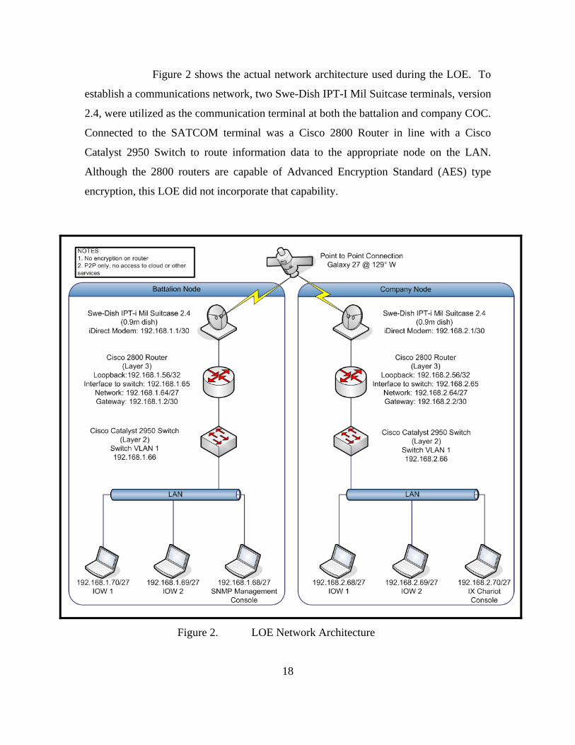
Figure 2 shows the actual network architecture used during the LOE. To
establish a communications network, two Swe-Dish IPT-I Mil Suitcase terminals, version
2.4, were utilized as the communication terminal at both the battalion and company COC.
Connected to the SATCOM terminal was a Cisco 2800 Router in line with a Cisco
Catalyst 2950 Switch to route information data to the appropriate node on the LAN.
Although the 2800 routers are capable of Advanced Encryption Standard (AES) type
encryption, this LOE did not incorporate that capability.
Figure 2. LOE Network Architecture

19
At the battalion node, one workstation served as the SNMP management
console, while a workstation at the company node served as the IX Chariot® console, or
controlling node. Various other workstations at both the battalion and company node
acted as IX Chariot® “endpoints,” which will be described in the Paragraph 1.c to follow.
The Swe-Dish IPTs, on loan from the Naval Postgraduate School’s Center
for Network Innovation and Experimentation (CENETIX), are Ku band (12-18 GHz)
terminals with 0.9m diameter Gregorian offset dishes. The system advertises a capability
of a 2Mbps duplex transmission of IP standard data, voice and video. Using MPEG2
video encoding the IPT Suitcase provides broadcast picture quality. With its 10/100 base-
T port, the system works as an ordinary LAN for email, FTP, VoIP and data streams. An
L-band port is optional.12 For additional technical information on the Swe-Dish IPTs, see
Appendix A.
b. Information Exchanges and Application Configuration
As previously discussed, the intent of the LOE was to test a particular set
of IERs over a specific network configuration to determine the feasibility that such a
network could support the information exchanges. The example battle rhythm, excerpted
directly from MCWL’s CLOC Concept of Employment (2007), will serve as a baseline
requirement for the amount and frequency of information exchanges occurring at the
company level.
EXAMPLE BATTLE RHYTHM
A 24-hour battle rhythm may include the following activities:
2345 Watch Officer change over
2345 Radio Watch change over
0000 CONOPS report due to Bn
0000 Ops/Intel NCO print digital watch log and place in binder
0530 Platoon POSREPs due to Co
12 Instructions for Use, IPT-I Mil Suitcase 2.4, Satellite Communications Terminal featuring iDirect,
CD-ROM, SWE-DISH Satellite Systems AB, 2007.

20
0545 Ops / Intel NCO change over
0600 Platoon personnel updates due to Co
0630 Platoon LOGSTATS due to Co
0630 Co POSREPs due to Bn
0645 Company ECP status reports due to Bn
0730 Intel (collections) change over
0745 Watch Officer change over
0745 Radio Watch change over
0745 Intel (analysis) change over
0800 CONOPS report due to Bn
1130 Platoon POSREPs due to Co
1200 Intentions message due to Bn
1230 Co POSREPs due to Bn
1345 Ops / Intel NCO change over
1400 Co personnel updates due to Bn
1400 Company personnel updates due to Bn
1430 Company LOGSTATS due to Bn
1430 Bn POSREPs due to Regt
1445 Company ECP status reports due to Bn
1530 Intel (collections) change over
1545 Watch Officer change over
1545 Radio Watch change over
1545 Intel (analysis) change over
1930 Platoon POSREPs due to Co
2000 Intentions message due to Bn
2030 Co POSREPs due to Bn
2200 Bn Personnel Stats due to Regt
2345 Watch Officer change over

21
Once the baseline is tested, the amount and frequency of exchanges will
be incrementally increased by simultaneously sending various information exchange
scenarios along with the previously discussed baseline. Detailed listings of those
information exchanges, excerpted from the U.S. Naval Research Laboratory Final
Report: Company and Below Command and Control Information Exchange Study
(2006), are included below.
DETAILED INFORMATION EXCHANGE REQUIRMENTS
1.2.1 Provide a Situation Report (SITREP) Goal: Pass important information through the chain of command. Description: Report information up the chain of command and horizontally when it is either critical, or an opportunity has presented itself to provide a larger report of less critical items. Communication:
Sender: Receiver: Monitor: Network: FT LDR SQD LDR Other FT LDRs Squad Net SQD LDR PLT CDR Other SQD LDRs Platoon Net PLT CDR Co CO Other PLT CDRs Company Net
Potential Exchanges:
Co CO BN CDR Other Co Cos Battalion Net Information Anything unusual such as trash that has not been picked up,
potential IEDs. The formality of the exchange will depend on proximity, urgency, and experience. The exchange is more likely to be formal at higher levels of command as more information is filtered out.
Purpose: Provide battlefield information to higher level of command and others at the same level of command.
Potential Problems:
Range limitations.
Recommended Format Recommended System HSI Recommended PLT CDR: Voice Comms
Co CO: Voice Comms AN/PRC-150 w/ D-DACT AN/PRC-117F (SATCOM)

22
1.2.2 Report Enemy Activity (SALUTE) Goal: Report Enemy Sighting and Movement up the chain of command. Description: Report information up the chain of command and horizontally regarding enemy sightings and movement. Information reported contains the enemy size, activities, location, unit identification, time, and equipment. Communication:
Sender: Receiver: Monitor: Network: SQD LDR PLT CDR Other SQD LDRs Platoon Net PLT CDR Co CO Other PLT CDRs Company Net
Potential Exchanges
Co CO BN CDR Other Co COs Battalion Net Information The formality of the exchange will depend on proximity, urgency,
and experience. The exchange is more likely to be formal at higher levels of command as more information is filtered out. A SALUTE Report contains Size of enemy force, Activities of the enemy, Location of enemy, Unit identification, Time, and Equipment carried by enemy.
Purpose: Provide intelligence on enemy movement to higher level of command and others at the same level of command.
Potential Problem Range limitations.
Recommended Format Recommended System HSI Recommended Plt CDR: Visual / Graphical
Co CO: Visual / Graphical AN/PRC-150 w/ D-DACT AN/PRC-117F (SATCOM)
1.5 Urgent Unformatted Reports
Goal: Provide information on current situation which requires immediate action Description: This is a generic communication for transmitting urgent information. It can be passed either up or down the chain. Communication:
Sender: Receiver: Monitor: Network: Bn Co CO Other PLT CDRs Battalion Net CoCO PLT CDR Other PLT CDRs Company Net PLT CDR SQD LDR Other SQD LDRs Plt Net
Potential Exchang
SQD LDR FT LDR Other FT LDRs Sqd Net Information The is a generic communication type and is used when urgent
information needs to be reported immediately up or down the chain of command. An example is a request for support.
Purpose: Provide actionable information to designated units. Potential Problem Range limitations.
Recommended Format Recommended System HSI Recommended PLT CDR: Voice Comms
Co CO: Voice Comms AN/PRC-150 w/ D-DACT AN/PRC-117F (SATCOM)

23
1.6 Routine Unformatted Reports Goal: Provide regular information on current situation which may not require immediate action Description: This is a generic communication for transmitting regular information. It can be passed either up or down the chain. Communication:
Sender: Receiver: Monitor: Network: Bn CDR Co CO Other Cc COs Battalion Net Co CO PLT CDR Other PLT CDRs Company Net PLT CDR SQD LDR Other SQD LDRs Plt Net
Potential Exchang
SQD LDR FT LDR Other FT LDRs Sqd Net Information The is a generic communication type and is used when regular
information needs to be reported immediately up or down the chain of command. An example is a request for support.
Purpose: Provide information to designated units. Potential Problem Range limitations.
Recommended Format Recommended System HSI Recommended PLT CDR: Voice Comms
Co CO: Voice Comms AN/PRC-150 w/ D-DACT AN/PRC-117F (SATCOM)
2.2 Distribute Intelligence to Lower Level of Command
Goal: Pass relevant intelligence down the chain of command Description: Report relevant battlefield intelligence down the chain of command. This will allow the lower levels of command to maintain a battlefield Situation Awareness. Actionable intelligence will be sent down the chain immediately.
Communication:
Sender: Receiver: Monitor: Network: Co CO PLT CDR Other PLT CDRs Company Net PLT CDR SQD LDR Other SQD LDRs Platoon Net
Potential Exchanges:
SQD LDR FT LDR Other FT LDRs Squad Net Information There is no official format for intelligence passed down the chain of
command. Purpose: Provide a “heads up” to lower levels of command. Potential Problems:
Range limitations.
Recommended Format Recommended System HSI Recommended Co CO: Visual/Graphical AN/PRC-150 w/ D-DACT

24
2.4 Request for Information (RFI) Goal: Plt CDR / Co CDR informs the Co CDR / BN of an intelligence need. Description: Subordinate LDR will request intelligence from higher. Communication:
Sender: Receiver: Monitor: Network: PLT CDR Co CO Other PLT CDRs Company Net Potential
Exchanges: Co CO BN CDR Other Co CO Battalion Net Information Subordinate LDR informs higher of what information they need Purpose: Indicate a need for intelligence to higher Potential Problems:
Range limitations.
Recommended Format Recommended System HSI Recommended Plt CDR: Voice
Co CO: Voice AN/PRC-150 w/ D-DACT AN/PRC-117F (SATCOM)
2.5 Request Intelligence from Battalion S-2
Goal: The Company Commander requests specific intelligence from the Battalion S-2 Description: The Platoon Commander goes to the battalion S-2 to request an intelligence update. The Platoon Commander would usually only go direct to Battalion if they were the only platoon ashore. Communication:
Sender: Receiver: Monitor: Network: Co CDR Bn S-2 N/A Battalion Net
Information The Company CO requests specific information from the Bn S-2.
Purpose: Solicit information from the Bn-S2. Potential Problems:
None assuming a single Platoon ashore with the Company CO monitoring communications in the Battalion Command Operations Center (COC). Leaving the Company network would not present any problems since the Company Commander will still be able to monitor the Platoon’s communications. Recommended Format Recommended System HSI
Recommended Co CO: Voice AN/PRC-117F (SATCOM)

25
3.1 Issue FRAG Order Goal: Provide Mission Order with Commander’s Intent to lower levels of command. Description: The Frag order is a fragment of the Operation Order (OPORD). It informs lower units of their responsibilities within the OPORD. It should ideally leave the specific details to the lower level of command. For example the Company CO may inform a Platoon CDR to set up ambushes within a general area and where to expect enemy movement. The Platoon CDR then decides where to place the Squads to set up the ambush. Communication:
Sender: Receiver: Monitor: Network: Bn CDR Co CO Other Co COs Battalion Net Co CO PLT CDR Other PLT CDRs Company Net PLT CDR SQD LDR Other SQD LDRs Platoon Net
Potential Exchanges:
SQD LDR FT LDR Other FT LDRs Squad Net Information Provide information on the mission objective and the commander’s
intent, but allowing flexibility on how the mission will be carried out. Ideally this should contain all 5 elements of SMEAC. Situation (enemy and friendly forces), Mission, Execution (Commander’s intent, concept of operation, etc), Administrative/Logistics, Command/Signal.
Purpose: Provide an objective to the Marine unit without necessarily forcing a specific solution.
Potential Problems:
No identified problems
Recommended Format Recommended System HSI Recommended Bn CDR: Visual / Graphical
Co CO: Visual / Graphical AN/PRC-117F (SATCOM) AN/PRC-150 w/ D-DACT
3.2 Position Report at Designated Area/Check Point Goal: The unit moves to either their designated area or their next checkpoint and then reports in. Description: Unit provides position reports to keep the commanding officer informed on where the unit is and when they will be at their next designated area. Communication:
Sender: Receiver: Monitor: Network: FT LDR SQD LDR Other FT LDRs Squad Net SQD LDR PLT CDR Other SQD LDRs Platoon Net PLT CDR Co CO Other PLT CDRs Company Net
Potential Exchanges:
Co CO Bn CDR Other Co COs Bn Net Information Identify commanding unit, your unit, and the brevity code for the
check point. Purpose: Update your commanding unit of your present position. Potential Problems:
Range Limitations
Recommended Format Recommended System HSI Recommended Co CO: Visual / Graphical
PLT CDR: Visual / Graphical AN/PRC-117F (SATCOM) AN/PRC-150 w/ D-DACT

26
6.2 Call for Fire (Artillery) Goal: Platoon Commander requests fire from the artillery FDC Description: Self explanatory.
Communication:
6.3 Message to Observer
Goal: Inform the observer who will be firing and what the volleys in effect are. Description: This is the message from the FDC to the observer that details who will fire, any changes to the CFF, the number of volleys in effect and the target number. Communication:
Sender: Receiver: Monitor: Network: Potential Exchanges:
Arty FDC
Co FST Arty Rep
Battalion COF
Information 1. Firing Unit 2. Changes/Additions to the CFF 3. Rounds in Effect (Number of Volleys) 4. Target Number
Purpose: Notify observer of any changes to the CFF and inform them of what the fire will be.
Potential Problems:
No identified problems
Recommended Format Recommended System HSI Recommended Co FST: Voice AN/PRC-150
Sender Receiver Monitor: Network: Potential Exchanges:
Co CO Arty FDC Battalion COF
Information Standard Call For Fire (CFF) format Purpose: Inform FDC about target so that artillery can be employed Potential Problems:
• Information is being relayed from initial source. Potential for interpretation errors in voice data transmission.
• Currently need to talk to the FDC and the observer on two different radios. Cannot have one listen in while relaying information to the other.
• The Platoon Commander would have to switch off the company net to go to the battalion FSCC net as both use the PRC-119/150.
• Inform FDC of where fire is going to increase the splash time.
Recommended Format Recommended System HSI Recommended Co CO: Visual / Graphical AN/PRC-150

27
6.4 Report Shot and Splash Goal: Notify Company Commander of incoming rounds. Description: Self explanatory Communication:
Sender: Receiver: Monitor: Network: Potential Exchanges:
Arty FDC
Co FST Arty Rep
Battalion COF
Information Shot is fired 1. Arty announce shot (i.e., “Shot over”) 2. Company acknowledges (i.e., “Shot out”)
Ten seconds before impact: 3. Arty announces “Splash over” 4. Company acknowledges “Splash out”
Purpose: Notify Company of shot fired and its predicted impact. Potential Problems:
No identified problems
Recommended Format Recommended System HSI Recommended Co FST: Voice AN/PRC-150
6.5 Adjust Fire (Artillery)
Goal: Redirect artillery fire so it is on target. Description: Self explanatory Communication:
Sender Receiver Monitor: Network: Potential Exchanges:
Co FST Arty Rep
Arty FDC Battalion COF
Information Notify FDC to shift fire Left/Right and Add or Drop
1. Identification (FDC this is_____) 2. Warning Order (either adjust fire, fire for effect, immediate
suppression, smoke, SEAD) ******FDC reads back information******* 3. Location of target (shift)
Purpose: Notify FDC to adjust mortar. Potential Problems:
• Range limitations.
Recommended Format Recommended System HSI Recommended Co FST: Voice AN/PRC-150

28
6.6 Inform FDC of artillery’s effect. Goal: Inform FDC of artillery’s effect on the target. Description: Self explanatory Communication:
Sender Receiver Monitor: Network: Potential Exchanges:
Co CO Arty FDC Battalion COF
Information Notify Artillery that the target has been destroyed, suppressed, or where additional fire should be delivered.
Purpose: Provide Artillery with a BDA Potential Problems:
• Range limitations force this step in the communication process.
Recommended Format Recommended System HSI Recommended Co FST: Voice AN/PRC-150
7.2 Request air asset from Fire Support Coordination Center (FSCC). Goal: Company commander seeks approval from FSCC to use an air asset to neutralize an identified target. Description: Company commander evaluates the request for air and uses their experience to determine whether an air asset should be used. If an asset should be utilized, they “forward” the information from the Platoon CDR to the FSCC. Communication:
Sender Receiver Monitor: Network: Potential Exchanges:
Co FST Air Rep
FSCC or SACC
TAR/HR
Information TAR: Unit identifier, priority, mission, payload, instructions, target type, location, assets being requested, desired ordnance/results, etc.
Purpose: Provide FSCC with information necessary to evaluate call for air with available assets and target priority. If necessary allocate the appropriate asset.
Potential Problems:
• Information is being relayed from initial source. Potential for interpretation errors in voice data transmission.
• Currently need to talk to the FSCC and the Observer/ Squad node on two different radios. Cannot have one listen in while relaying information to the other.
• If Aircraft is not available FSCC or currently under the FSCC’s control they may need to keep the company commander on “hold” thus potentially keeping them off the company net.
Recommended Format Recommended System HSI Recommended Co FST: Visual/Graphical AN/PRC-117F (SATCOM)

29
7.4 Air Asset and Observer coordinate attack (9 Line) Goal: Neutralize target. Description: The Observer has been told the CFF has been approved, and is provided information on contacting the Air Asset. The Observer communicates with asset to coordinate the attack and provides a standard nine line. Communication:
Sender: Receiver: Monitor: Network: Potential Exchanges:
Co FST Air Rep
Air Asset FSCC Air Asset’s Frequency
Information Standard “9-Line” Format
Purpose: Provide target information to the air asset; neutralize the target. Potential Problems:
• De-confliction with other forces in area is traditionally done at the platoon or Co level.
Recommended Format Recommended System HSI
Recommended Co FST: Visual/Graphical (w/ audio)
AN/PRC-150 with D-DACT
7.5 Air Asset Enters Target Area and Confirms Target Goal: The observer makes visual contact with the air asset and confirms the target. Description: The air asset enters into the designated air space and requests confirmation from the observer. The observer visual identifies the air asset is lined up and confirms the attack. Communication:
Sender: Receiver: Monitor: Network: Potential Exchanges:
Co FST Air Rep
Air Asset FSCC Air Asset’s Frequency
Information • Aircraft will announce that they are inbound and distance from target
• Observer will inform aircraft to continue • Observer will inform aircraft of where the target is from the
mark. • Aircraft goes into “the pop” and observer confirms aircrafts
location. • Aircraft goes “wings level” and proceeds to target • Observer confirms aircraft is inbound to target and announces
“Cleared Hot” Purpose: Confirm target location and direct aircraft to the target. Potential Problems:
No identified problems
Recommended Format Recommended System HSI Recommended Co FST: Voice AN/PRC-150 with D-DACT

30
7.6 Observer reports Battle Damage Assessment (BDA) of target back to Air Asset. Goal: Report effectiveness of attack. Description: The Observer communicates with Air Asset to report damage to target. Communication:
Sender: Receiver: Monitor: Network: Potential Exchanges:
Co FST Air Rep
Air Asset FSCC Air Asset’s Frequency
Information Target neutralized, damage assessment, new coordinates, etc. Purpose: Provide damage information to the Air Asset Potential Problems:
• Aircraft may leave the area (range issue)
Recommended Format Recommended System HSI Recommended Co FST: Voice AN/PRC-150 with D-DACT
8.1 Call for Fire (Naval Gunfire)
Goal: The company commander requests fire from Naval Guns Description: Self explanatory Communication:
Sender Receiver Monitor: Network: Potential Exchanges: Co CO Naval FDC ? Information Standard Call For Fire Format
Purpose: Inform FDC about target so that artillery can be employed Potential Problems: • Information is being relayed from initial source. Potential for
interpretation errors in voice data transmission. • Inform FDC of where fire is going to increase the splash time.Recommended Format Recommended System HSI Recommended Co FST: Voice AN/PRC-117F (SATCOM)

31
8.2 Message to Observer Goal: Inform the observer who will be firing and what the volleys in effect are. Description: This is the message from the FDC to the observer that details who will be firing, any changes to the CFF, the number of volleys in effect, and the target number. Communication:
Sender: Receiver: Monitor: Network: Potential Exchanges:
Naval FDC
Co CO
Information 1. Firing Unit 2. Changes/Additions to the CFF 3. Rounds in Effect (Number of Volleys) 4. Target Number
Purpose: Notify observer of any changes to the CFF and inform them of what the fire will be.
Potential Problems: No identified problems Recommended Format Recommended System HSI Recommended Co FST: Voice AN/PRC-117F (SATCOM)
8.3 Splash and Shot (Naval Gunfire)
Goal: Round is released on target based upon CFF Description: Naval gun battery fires round and FDC announces shot and splash. The Announcement is passed down the chain to the observer. Communication:
Sender: Receiver: Monitor: Network: Naval FDC Co CO Potential
Exchanges: Co CO PLT CDR Other PLT CDRs Company Net Information Shot is fired
1. FDC announces shot (i.e., “Shot over”) 2. Co CO acknowledges (i.e., “Shot out”) 3. Co CO announces shot (i.e., “Shot over”) 4. PLT CDR acknowledges (i.e., “Shot out”)
Fifteen seconds before impact: 5. FDC announces “Splash over” 6. Co CO acknowledges “Splash out”
Ten Seconds before impact: 7. Co CO announces “Splash over” 8. PLT CDR acknowledges “Splash out”
Purpose: Notify Platoon of shot fired and its predicted impact. Potential Problems:
No identified problems
Recommended Format Recommended System HSI Recommended Co FST: Voice
PLT CDR: Voice AN/PRC-117F (SATCOM) AN/PRC-150

32
8.4 Adjust Fire (Naval Gunfire) Goal: Redirect Naval gunfire so it is on target. Description: Self explanatory Communication:
Sender Receiver Monitor: Network: PLT CDR Co CO Other PLT CDRs Company Net Potential
Exchanges: Co CO Naval FDC Information Notify FDC to shift fire Left/Right and Add or Drop
1. Identification (FDC this is_____) 2. Warning Order (either adjust fire, fire for effect, immediate
suppression, smoke, SEAD) ******FDC reads back information*******
3. Location of target (shift) Purpose: Notify FDC to adjust fire. Potential Problems:
Range limitations.
Recommended Format Recommended System HSI Recommended Co FST: Voice
PLT CDR: Voice AN/PRC-117F (SATCOM) AN/PRC-150
8.5 Report on Rounds Effect (Naval Gunfire)
Goal: Provide information up the chain of command regarding effectiveness of naval gunfire. Description: Self explanatory Communication:
Sender Receiver Monitor: Network: PLT CDR Co CO Other PLT CDRs Company Net Potential
Exchanges: Co CO Naval FDC Information Notify up the chain of command that the target has been destroyed,
suppressed, or where additional fire should be delivered. Purpose: Inform the commanders on effectiveness of delivered rounds. Potential Problems:
• Range limitations force this step in the communication process. • This slows down the speed of the CFF. Recommended Format Recommended System HSI
Recommended Co FST: Voice PLT CDR: Voice
AN/PRC-117F (SATCOM) AN/PRC-150

33
10.1 Issue a Warning Order Goal: A Warning Order is issued to allow a unit to prepare for an upcoming order. Description: A warning order is issued to provide a unit to time to prepare for an upcoming order. It should contain as much information as is available at the time and follow the 5 paragraph SMEAC format as closely as possible. Communication:
Sender: Receiver: Monitor: Network: Potential Exchanges:
CO Co PLT CDR Other PLT CDRs Company Net
Information There is no official format for warning orders. It may include elements of a SMEAC or may simply instruct a unit to prepare to move out.
Purpose: Provide a “heads up” to lower levels of command that an order will be coming down the chain.
Potential Problems:
Range limitations.
Recommended Format Recommended System HSI Recommended Co FST: Visual / Graphical AN/PRC-150 w/ D-DACT
11.1 Battalion Issues OPORD
Goal: Company Commander Receives the Operation Order from the Battalion Description: The Operations Order (OPORD) it usually follows the 5 paragraph SMEAC format. It sets forth the Situation, the Mission, the plan and method of Execution, Administration and Logistics, and Command and Signal information. Communication:
Sender: Receiver: Monitor: Network: Potential Exchanges:
Battalion CDR
Co CO Other Co COs Battalion Net
Information Provide information on the mission objective and the commander’s intent, but allowing flexibility on how the mission will be carried out. Ideally this should contain all 5 elements of SMEAC. Situation (enemy and friendly forces), Mission, Execution (Commander’s intent, concept of operation, etc), Administrative/Logistics, Command/Signal. The OPORD is a more formal document and may be distributed in a digital format.
Purpose: Provide an overall objective to the Marine unit without necessarily forcing a specific solution.
Potential Problems:
No identified problems
Recommended Format Recommended System HSI Recommended Co CO: Visual / Graphical AN/PRC-117F (SATCOM)

34
13.1.2 Request Supplies from Combat Supporting Supply (CSS) Goal: Acquire supplies from the Battalion’s Combat Supporting Supply Description: Self explanatory Communication:
13.2.1 Casualty Report (CASREP)
Goal: Inform commanding unit on wounded. Description: Self explanatory Communication:
Sender: Receiver: Monitor: Network: PLT CDR CO Co Other PLT CDRs Company Net Potential
Exchanges: Co CO BN CDR Other Co Cos Battalion Net Information Number of casualties, types of injuries, urgency of request. Purpose: Inform command unit on injuries. Determine the appropriate
course of action for handling wounded. Potential Problems:
No identified problems
Recommended Format Recommended System HSI Recommended Co CO: Voice AN/PRC-117F (SATCOM)
Sender: Receiver: Monitor: Network: Potential Exchanges:
Co CO CSS Battalion Net
Information Unit Identification, location, types of supplies needed, urgency of request.
Purpose: Acquire supplies from the Battalion’s Combat Supporting Supply Potential Problems:
No identified problems
Recommended Format Recommended System HSI Recommended Co CO: Visual / Graphical AN/PRC-117F (SATCOM)

35
13.2.2 Request Casualty Evacuation (CASEVAC) from Battalion Goal: Have a serious casualty moved from the battlefield for immediate care. Description: Self explanatory Communication:
Sender: Receiver: Monitor: Network: SQD LDR Battalion PLT CDR, Co CO PLT CDR Battalion Co CO
Potential Exchanges:
Co CO Battalion Information Number of casualties, types of injuries, urgency of request. Purpose: Inform command unit on injuries. Request immediate extraction of
critically wounded marines. Potential Problems:
Range limitations.
Questions What radio would be used? Recommended Format Recommended System HSI
Recommended ? ? 13.2.3 Battalion Responds to CASEVAC Request and Provides Contact Information
Goals: Provide information to CASEVAC requester on how CASEVAC will occur. Description: Self explanatory Communication:
Sender: Receiver: Monitor: Network: Battalion SQD LDR PLT CDR, Co CO ?? Battalion PLT CDR Co CO
Potential Exchanges:
Battalion Co CO Information Type of CASEVAC asset that is inbound, how to contact asset,
when asset will arrive. Purpose: Provide information to CASEVAC requestor on how CASEVAC
will occur. Potential Problems:
No identified problems
Recommended Format Recommended System HSI Recommended ? ?

36
SOFTWARE APPLICATIONS
The MCWL concept of employment for the Company Level Operations
Center details several software applications to be made available for CLOC personnel to
pass IERs via electronic means (e.g., e-mail attachments, live chat, etc.) vice traditional
voice reports sent via portable radios. The paragraphs to follow provide detail regarding
applications included at each CLOC work station.
COMMAND AND CONTROL PERSONAL COMPUTER (C2PC)
Intelligence Operations Workstations (IOWs) are the equipment suite,
which provide automated support to the CLOC via the C2 application called C2PC. An
IOW is simply a laptop inside the CLOC, which is pre-loaded with C2PC and many other
software applications. C2PC provides map overlays, friendly unit locations with status
and plans of intended movement, and hostile unit locations. C2PC is linked together
within the CLOC via a Local Area Network (LAN) allowing rapid information exchange
between staff sections, and they are also linked with adjacent, subordinate, and higher
headquarters via a Wide Area Network (WAN). Using the Intelligence Operations Server
(IOS), C2PC also links with the Intelligence Analysis System (IAS) for the reception of
intelligence information and may be linked with the Enhanced Position Location and
Reporting System (EPLRS) network (if used). C2PC provides an automated message
generation and validation capability for the exchange of MTF messages and a capability
to generate and validate Variable Message Format (VMF) messages. C2PC has multiple
injectors that allow modular systems with an interface with other capabilities such as
AFATDS through the Effects Management Tool (EMT).
C2PC Capabilities:
• Facilitates C2 functions
• Displays the CTP
• Simultaneously displays multiple, independent map windows
• Capable of displaying multiple areas of interest
• Supports over 200 different mapping datum

37
• Allows users to display mapping features including political boundaries,
rivers, and major roadways
FORCE XXI BATTLE COMMAND BRIGADE AND BELOW – BLUE
FORCE TRACKER (FBCB2-BFT)
Force XXI Battle Command Brigade and Below (FBCB2) – Blue Force
Tracker (BFT) is a battle command information system designed for units performing
missions at the tactical level. FBCB2-BFT displays the relevant SA picture of the
battlefield. SA shows the user his location, the location of other friendly forces, observed
enemy locations, and all known battlefield obstacles. FBCB2-BFT will be employed by
the regimental CLOC, battalion CLOC, each company CLOC, and convoys and/or
patrols traversing throughout the area of operations (AO). A significant advantage of
FBCB2-BFT is that the information is passed via L-Band satellite. This means that it is
not limited to Line-of-Sight (LOS) characteristics of the EPLRS network.
FBCB2-BFT Capabilities
• Automated Positional Reporting
• Displays Maneuver Graphics
• Free text and formatted messaging capability
• Over the Horizon (OTH) communications
• Message Transmitter providing ID, GPS location, Course, and Speed
BIOMETRIC AUTOMATED TOOLSET (BAT)
BAT provides a means of identifying people via fingerprint, iris scan, and
photo identification (ID), which enables the creation of individual records. The system
includes a laptop with the BAT software, a fingerprint scanner, an iris scanner, a digital
camera, and an ID card printer. ID badges can be provided to residents of a city or other
identified geographic area. By controlling the routes in and out of cities via Entry Control
Points (ECPs), and only providing positively identified residents with badges, it creates
an obstacle to others posing as residents. Using iris scans or fingerprints, Marines at
ECPs can verify identity via connectivity to the shared records database. The Marine can

38
access information such as the person’s birth date, occupation, place of residence, and
any documentation addressing affiliation with anyone involved in terrorist activities.
BAT Capabilities:
• Efficiently enroll, verify, and identify individuals encountered in the
conduct of operations
• Rapidly compare identity information to watch lists.
• Rapidly record various types of information associated with an
individual
• Rapidly recall, update, and manage ‘trusted’ information associated with
individuals
• Rapidly assess credibility of a witness
• Operates remotely/non-intrusively against non-cooperative subjects
MARINELINK
MarineLink is designed to allow analysts to mine internal and external
data sources, visually display the data on a map, store the data locally, and generate
products and reports to help disseminate the information and intelligence. This program
is provided as part of the Intelligence Analysis System (IAS) software package that is on
all IOW computers.
Importance of MarineLink to the CLOC
Using MarineLink, users can visualize data within the map viewer, filter
or sort results, generate graphs, copy data from an external data source to Intel Tracker,
and copy data into Report Builder. It allows users to quickly search, sort, build graphs
and reports, and provides information in a usable format. MarineLink reduces the amount
of time required to do these tasks.
Sources that MarineLink Can Query
MarineLink supports data mining, pattern analysis, and trends and tactics
analysis. It provides the ability to query the following data sources:

39
• All Source Analysis System-Light (ASAS-L) – Army S-2
• Analyst Notebook (Link Analysis Charts)
• BAT and HIIDE systems (Biometric Databases)
• C2PC overlays and tracks (C2PC 6.1.1 required)
• Digital Aeronautical Flight Information File (DAFIF)
• Google Desktop (Documents/email stored on your computer)
• Gazetteer (Geographic place-names if the world)
• Imagery Product Library (IPL) (National, Theater and MEF-level Geo-
rectified imagery)
• Intel Tracker (as available from unit and external sources)
• Local Map Server (Raster, CIB, DTED maps)
• Modernized Integrated Database (MIDB) (DIA database of worldwide
General Military Intelligence)
c. Experiment Metrics
The IX Chariot® software used in this experiment makes three basic types
of measurements that are useful when determining network performance. The
measurements include throughput, transaction rate, and response time. For this
experiment the software was installed on one of the nodes at the CLOC; this laptop
served as the “console,” which sends scripts to “endpoints” and also collects polling data
sent from the endpoints. In this particular LOE only two endpoints were established,
although the user’s manual states the software can manage thousands of endpoints which
will simulate very large networks. See Appendix B for a more detailed explanation of the
software. The following paragraphs define, according to the IX Chariot® user’s manual,
how the software calculates each of the metrics.

40
Throughput is defined as the “amount of data that a medium can transmit
during a given period of time.” 13 IX Chariot® calculates throughput for a pair of
endpoints in a non-streaming script using the following equation:
(Bytes_Sent+Bytes_Received_By_Endpoint_1) / Throughput_Units) / Measured_Time14
The transaction rate is the number of script transactions that are executed
per second. What defines a transaction depends on the particular script. In general a
single transaction is one loop through a particular scripts actions, for example, in a file
send script a transaction would include the file request, the acknowledgement of request,
the file being sent and the acknowledgement of receipt. Transaction rate is calculated by
IX Chariot® using the following formula:
Transaction_Count / Measured_Time15
The final set of data collected during the experiment was response time.
The response time is the inverse of the transaction rate. The calculations are shown in
seconds per transaction. This value is calculated as follows:
Measured_Time / Transaction_Count16
d. Experiment Scripts
During this LOE, fourteen IX Chariot® default scripts were run as well as
two tests that involved the actual collaborative software applications, mIRC Chat and
Microsoft’s NetMeeting. The following is a list of the IX Chariot® scripts. Unless
otherwise noted each script was run between one pair of endpoints, utilizing the Internet
Protocol (IP) core protocol, Transmission Control Protocol (TCP). All script descriptions
are excerpted from the IX Chariot® Scripts and Streams Library Reference, release 6.50,
Revision A, 2007.
13 Tamara Dean, Network+ Guide to Networks (Massachusetts: Course Technology,2006), 144. 14 IX Chariot User Guide, CD-ROM Release 6.50, IXIA, 2007. 15 Ibid. 16 Ibid.

41
1. Throughput.scr: In Throughput.scr, Endpoint 1 sends a 100,000 byte file to
Endpoint 2. Endpoint 2 sends an acknowledgment upon receipt of the file.
2. Throughput.scr: Same as above utilizing User Datagram Protocol (UDP).
3. Responsetime.scr: This script tests network response time. Endpoint 1 sends a
100-byte file; Endpoint 2 receives it and sends an acknowledgment.
4. Responsetime.scr: Same as above utilizing UDP.
5. Filesndl.scr: File Send, Long Connection. Endpoint 1 requests and receives a file;
Endpoint 2 sends the requested file and receives an acknowledgement. One
connection is made for the entire transaction.
6. Filercvl.scr: File Receive, Long Connection. The pair script to File Send. Two
endpoints interact to send and receive a 100,000 byte file. The request and
acknowledgement default to 100 bytes.
7. DBaseL.scr: Database Update, Long Connection. The database update scripts are
the most complex of the benchmarks. These scripts emulate a program that
requests a record from Endpoint 2, receives it, updates it, and sends it back.
Last, Endpoint 1 receives a confirmation that the update was completed. All
file sizes default to 100 bytes.
8. SMTP_Payload.scr: The SMTP_Payload.scr script emulates the sending of one or
more email messages over a TCP network. The default size of an email
message is 1,000 bytes, with an additional 20-byte header. In addition to a
login/logout sequence, payload data is included for an email containing an
IxChariot newsletter notice.
9. activeFTPget_Payload.scr: This script emulate sending a file from Endpoint 1,
using active-mode FTP. Only the data channel is emulated, and an active
(versus passive) connection is used. The script emulates the transfer of an
IxChariot newsletter file. The activeFTPget_Payload script is designed to
emulate the actual file transfer portion of an FTP transaction.

42
10. HTTPText_Payload.scr: These scripts emulate the transfer of graphics and text
files from an HTTP server for the Web page:
http://www.ixiacom.com/about_us/. The actual request and data are enclosed
in embedded payloads.
11. ICQ_Text_Chat.scr: The text chat scripts emulate an IRC client sending the word
Hello to a receiving IRC client on his buddy list. The receiving IRC client
responds with the words Hello back. A number of IRC Text chat scripts (for
example, Microsoft) include a more explicit client authentication and join
process between the two clients prior to the message exchange. All scripts
include a separate loop to allow the user to determine the exact count of
messages that are being exchanged. The default number of messages is set to
ten (10) per transaction. In addition, prior and post any message send requests,
SLEEP commands have been added to the script to simulate the users either
typing or reading the message. The default setting for each SLEEP is zero
seconds.
12. Netmtgv.scr: These script emulate sending video streams, using Microsoft
NetMeeting v2.1 over a 100 Mbps Ethernet LAN. Along with the audio or
video traffic, a small amount of control traffic is exchanged between the
participating computers using a different port number pair. The control traffic
is not emulated in these scripts. The send_data_rate is set to 64 kbps. The
type value for the RTP_PAYLOAD_TYPE is set to H261 for H.261.
13. HTTP_Streaming.iag: This application group uses two pairs to emulate an HTTP
session with streaming video data. The HTTP session involves these tasks:
1. Browse to a Web page containing a video link.
2. Select the video link.
3. View the video in the player that is automatically opened when the link
is selected.
The first pair provides the Control connection, via the
HTTP_streaming_control.scr script. The control connection is a TCP
connection that emulates browsing to a Web page and clicking on a video

43
link. The second pair provides the Data connection, via the
HTTP_streaming_data.scr script. This connection emulates the video
streaming from the Web server to the user's desktop.
14. active_FTP.iag: This application group uses two pairs to emulate the two
connections needed to accomplish an active FTP operation. In active mode
FTP, the client connects from a random unprivileged port (the port number is
higher than 1,024) to the FTP server's command port (port 21). Then, the
client starts listening to port N+1 and sends the FTP command PORT N+1 to
the FTP server. The server then connects back to the client's specified data
port from its local data port (port 20). The first pair provides the Control
connection, via the active_FTP_control.scr script. The second pair provides
the Data connection, via the active_FTP_data.scr script.
e. Impact of Concurrent Experiment
As mentioned earlier, another Master’s degree candidate was running,
concurrent with this LOE, an experiment on the feasibility of network management using
SNMP in an effort to determine if a SATCOM type network could be managed from
higher headquarters in an effort to ease the manpower and training impact adoption of
SATCOM technology at a company level would incur. The SNMP console was running
the commercial software SolarWinds Engineering Edition as the network management
application, and was responsible for collecting data on network performance and was the
originator of network management-related tasks. In addition to running SolarWinds, the
management host was also running the traffic analyzer Wireshark, which was used to
capture packets traversing from the management agent to the rest of the network. In
addition to the transfer of the IX Chariot® Scripts across the network, the management
agent set a polling interval for SNMP data at 120 to 240 seconds. The SNMP data sent
over the network included User Data Protocol (UDP) datagrams which contained the
polling data and the Internet Control Message Protocol (ICMP) messages encapsulated
within an Internet Protocol (IP) datagram. SNMP is typically a 64 bit datagram, while
ICMP, a Network layer protocol that indicates data delivery success or failure, can range

44
between 576 bytes to 65 kilobytes.17 Although the overhead associated with remote
network management will decrease the overall bandwidth available to pass IERs and
should always be considered when testing a new material solution for networked
communication, the SNMP traffic across the network was consistent for each of the
scripts run during this LOE, and therefore overhead will become transparent in a
comparison of the different types of IER scripts.
B. EXPERIMENT UTILITY
The LOE for this thesis was scheduled to take place from 0800 on Monday,
August 4, 2008 through 1600 on Thursday, August 7, 2008. Day one (Monday) was to
include a half day of set-up with baseline testing to begin in the afternoon. The
remaining days were to be used to test an incremental increase in the number of scenario
scripts passed across the network. Encryption would be applied, and the same tests run
again. However, due to issues with the software operating system on one of the Swe-
Dish IPTs, it took three days, with extensive phone support from a Swe-Dish technical
representative to establish the satellite connection. This setback left only Thursday for
actual testing. With one day to gather data on test scripts that at times took upwards of
four hours to run to completion only the most basic testing was completed. For purposes
other than base lining one particular small aperture satellite configuration all but two of
the tests provide no utility in determining whether or not SATCOM is a viable solution to
meet the IERs at CLOC. Those two tests, where mIRC Chat and NetMeeting were used,
each provided data demonstrating that a specific disadvantaged terminal can support
multiple types of traffic broadcast over the network at the same time using actual
applications installed on the operating workstations. Another shortcoming induced by the
equipment malfunction and subsequent decreased timeline include the lack of any
measurements on the effects encryption would have had on the performance of the
network in supporting the exchange requirements.
Given the previously mentioned lack of a standard list of IERs for units smaller
than a battalion, it was determined that even if the experiment had been executed
17 Tamara Dean, Network+ Guide to Networks (Massachusetts: Course Technology, 2006).

45
according to plan that particular set of data would only have been representative at most
of one particular battalion’s opinion of what exchanges should be measured. Such data,
measured for utility across infantry companies throughout the Marine Corps, is as useful
as no data. While the LOE failed to provide the data necessary to meet the primary thesis
objective the process of researching a validated list of IERs provided a much better
understanding regarding how similar experiments should be conducted in the future. The
data gathered during one day of testing is provided in the next chapter, including an in
depth analysis of the last test scenario, while the remaining portions of the thesis will
emphasize those actions required to make similar testing valuable to the designers of
future communication networks utilizing SATCOM.
Although the IPT malfunction decreased the utility of this LOE as a tool for future
Marine Corps communications architects detailing possible solutions for an Enhanced
Company, the reader should note that the Swe-Dish terminals employed in this
experiment have successfully been used as a means to pass comparable information
exchanges in other experiments run by the Naval Postgraduate School’s CENETIX
Laboratory. The authors have personally used the equipment in a number of the lab’s
Tactical Network Topology (TNT) series of experiments, whose objective is the study of
”multiplatform tactical networks, Global Information Grid connectivity, collaborative
technologies, situational awareness systems, multi-agent architectures, and management
of sensor-unmanned vehicle-decision maker self-organizing environments.”18 The TNT
experiments have previously focused on the use of the 802.16 wireless standard and
traditional RF radio technology during scenarios that include the passing of biometric
data between deployed forces and a local operations center as well as the maritime
interdiction of possible Weapons of Mass Destruction (WMD) material. The scenarios
first incorporated SATCOM as a backup link to the primary wireless link. During several
experiments the wireless link did indeed fail and the Swe-Dish terminal provided a
backup capability that proved transparent to the users; allowing each node to seamlessly
continue the same information exchanges and use the same situational awareness
18 “Center for Network Innovation and Experimentation,” Center for Network Innovation and
Experimentation, http://cenetix.nps.edu/cenetix/ (accessed September 15, 2008).

46
building software applications as before the failure with no noted degradation in service.
Recently, the TNT experiments have begun to include point to point configurations using
the Swe-Dish terminals to successfully connect nodes in several states as well as nodes as
far away as Europe.
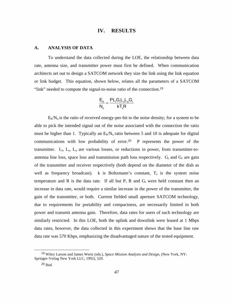
47
IV. RESULTS
A. ANALYSIS OF DATA
To understand the data collected during the LOE, the relationship between data
rate, antenna size, and transmitter power must first be defined. When communication
architects set out to design a SATCOM network they size the link using the link equation
or link budget. This equation, shown below, relates all the parameters of a SATCOM
“link” needed to compute the signal-to-noise ratio of the connection.19
=b l t s a r
o s
E PL G L L GN kT R
Eb/No is the ratio of received energy-per-bit to the noise density; for a system to be
able to pick the intended signal out of the noise associated with the connection the ratio
must be higher than 1. Typically an Eb/No ratio between 5 and 10 is adequate for digital
communications with low probability of error.20 P represents the power of the
transmitter. Ll, Ls, La are various losses, or reductions in power, from transmitter-to-
antenna line loss, space loss and transmission path loss respectively. Gt and Gr are gain
of the transmitter and receiver respectively (both depend on the diameter of the dish as
well as frequency broadcast). k is Boltzmann’s constant, Ts is the system noise
temperature and R is the data rate. If all but P, R and Gt were held constant then an
increase in data rate, would require a similar increase in the power of the transmitter, the
gain of the transmitter, or both. Current fielded small aperture SATCOM technology,
due to requirements for portability and compactness, are necessarily limited in both
power and transmit antenna gain. Therefore, data rates for users of such technology are
similarly restricted. In this LOE, both the uplink and downlink were leased at 1 Mbps
data rates, however, the data collected in this experiment shows that the base line raw
data rate was 570 Kbps, emphasizing the disadvantaged nature of the tested equipment.
19 Wiley Larson and James Wertz (eds.), Space Mission Analysis and Design, (New York, NY:
Springer-Verlag New York LLC, 1992), 520. 20 Ibid.

48
A point to consider when examining the data is the fact that IX Chariot® measures
only the throughput associated with the Internet Protocol (IP) packet payload and
disregarding the 198 bit IP headers associated with the traffic. Therefore the data
represents throughput that is actually less than what was actually passed over the
network.
Also, keep in mind that while the IX Chariot® test scripts were being executed, a
small amount of network management traffic was simultaneously injected into the
network which subsequently reduced the bandwidth available for data generated by the
test scripts. However, since the SNMP traffic was running at a set interval for all tests its
effect was constant for all the scripts it could be considered insignificant for comparisons
of two or more types of test scripts.
Table 2 shows the average throughput, transaction rate and response time from
the IX Chariot® test console for all tests except the final two which utilized actual
software applications previously loaded onto workstations at both the battalion and
company nodes. A separate application, Wireshark, was used to capture the data for the
mIRC and NetMeeting based exchanges.
The first two tests were run to determine the baseline capability of the tested
network configuration. The response time results concur with expected response times
for a transmission link with a geostationary communications satellite. For the purpose of
this LOE, a non-streaming script is one that requires two way communication while
streaming scripts require one-way flow at a specific data rate.21
21 IX Chariot® Scripts Development and Editing Guide, CD-ROM Release 6.50, Version 1.9, IXIA,
2008.

49
SCRIPT THROUGHPUT
AVG. (Mbps)
TRANSACTION RATE
AVG. (# / sec.)
RESPONSE TIME
AVG. (sec.)
Throughput1 0.570 0.715 1.398
Response time1 0.003 1.971 0.507
File Send Long1 0.586 0.735 1.361
File Rec. Long1 0.587 0.736 1.359
Data Base1 0.002 0.986 1.014
SMTP Payload1 0.012 0.237 4.225
FTP Get (Active) 1 0.033 0.826 1.211
HTTP Text Payload1 0.108 1.427 0.701
ICQ Text Chat1 0.016 0.143 7.001
NetMeeting (Video)2 0.064 Not measured Not measured
HTTP Streaming2 0.876 1.974 22.889
Active FTP1 0.093 1.037 2.365
mIRC (Actual)2,3 0.400 Not measured 0.510
NetMeeting (Actual)2,3 0.400 Not measured 0.510
1 – Non-streaming script
2 – Streaming script
3 – Data pulled from Solar Winds software program vice IX Chariot® Table 2. Summary of LOE Data
The final test set, using NetMeeting, was the most comprehensive, and was
originally developed to stress the satellite link. This particular test consisted of multiple
NetMeeting protocols being transferred simultaneously, specifically a video and text chat
session, a file transfer, and an application share, where the receiving node of the
exchange has access to the sender’s desktop applications. Microsoft’s TechNet website,
explains that NetMeeting utilizes both the TCP standard for data transport and call
control, and the UDP standard for secondary connections for sending and receiving audio

50
and video.22 As with the previous test sets, the presence of the ICMP and SNMP
management data is purposely injected by the network management agent. Comparing
this last sample with the previous, there is a marked increase in the receive/transmit
kilobits per second (Kbps) on each of the two nodes. Figure 3 shows throughput at levels
almost the advertised data rate of the leased satellite channels.
Figure 3. Portion of screen shot from NetMeeting test
22 “NetMeeting 3.0 Resource Kit,” Microsoft Tech Net, http://technet.microsoft.com/en-
us/library/cc767134.aspx (accessed September 8, 2008).

51
B. COMPARISON OF TESTED SCRIPTS TO SOFTWARE IN MCTOG CLOC CONCEPT APPLICATIONS
Table 3 maps the IX Chariot® scripts to the applicable MCTOG software
requirements. Development of this table was difficult due to lack of information on the
majority of the MCTOG software. Repeated attempts to gain detailed information
(packet sizes, protocols used, and frequency of exchanges) were hampered because most
of the software is proprietary and vendors were not forthcoming with the information.
Based on discussion with MCWL representatives and Marines, the MCTOG software
was mapped back to the IX Chariot® scripts as follows.
IX Chariot® Script MCTOG Software
Filesndl.scr
MarineLink
C2PC
BAT
FBCB2-BFT
Filercvl.scr
MarineLink
C2PC
BAT
FBCB2-BFT
DBaseL.scr
MarineLink
C2PC
BAT
SMTP_Payload.scr C2PC
activeFTPget_Payload.scr BAT
HTTPText_Payload.scr C2PC
ICQ_Text_Chat.scr mIRC
Netmtgv.scr mIRC
HTTP_Streaming.iag VTC
active_FTP.iag C2PC
BAT Table 3. Comparison of IX Chariot® Script to MCTOG Software Applications

52
THIS PAGE INTENTIONALLY LEFT BLANK

53
V. CONCLUSION AND RECOMMENDATIONS
A. WHAT WAS LEARNED
The main objective of this thesis was to conduct an LOE on a particular
SATCOM terminal technology against a standardized list of small unit IERs. However,
through research, it was determined that no such list existed and that results of
experimentation regarding IERs are of no value until the Marine Corps develops a
consistent list that applies to company and below sized units. Important insight to the
second and third order impacts of fielding SATCOM technology at the less than battalion
size unit will help expand the evaluation metrics of future LOEs beyond a purely data
centric measurement set. During research for this thesis, the authors conversed with
many stakeholders regarding the exact nature of which information exchange
requirements were required for isolated decision-making. To our surprise, although there
are many different research bodies genuinely interested in defining IERs for company
and below sized units, there exists no definitive sources for this information and there is a
noticeable lack of coordination between the various efforts to determine a standardized
list.
Despite the previously noted shortcomings of the limited objective experiment,
the authors learned a tremendous amount regarding the minutiae involved in finding and
evaluating solutions to the problem of providing the technical support needed by a small
unit leader to make decisions in an isolated environment. Based on the knowledge
gained over the past months the authors provide the following recommendations
regarding the objectives of this thesis as well as some strategic recommendations on the
subject of procuring technical solutions in support of information exchange requirements
required for the asymmetric battlefield of today and the future.
B. SATCOM TERMINAL RECOMMENDATION
1. Proof of Concept
Although only supported with one set of data points, the results of the final
NetMeeting test script serve as a proof of concept that two disadvantaged terminals were

54
capable of managing an sufficient collection of simultaneously transmitted application
protocols, in addition to network management related data. The following additions to
the LOE will serve to improve the utility of the experiment:
• To provide a more concrete data, a similar test should be scheduled with
ample time to run test scripts in their entirety as well testing of scenarios
containing multiple application protocols.
• The test should include or simulate the exact specifications and protocols of
the determined set of applications that will support the isolated decision
maker.
• Due to the nature of military communications, security is paramount.
Therefore, the test should be run again with encryption applied. The data
derived from this experiment can be compared to the unencrypted data set to
provide knowledge on the impact of encryption on required bandwidth.
• Because disadvantaged users are physically limited to data rates,
enhancements, such as IP accelerators should be tested as a method of
improving the capacity of such networks.
• All of these tests should only be conducted after a line item list of IERs and
their associated applications or modes of transmittal are validated by the user,
namely the small unit leader.
2. Higher Order Impacts
In addition to the purely data centric metrics above, consideration should be made
regarding the impacts of fielding new equipment will have on manpower, training,
logistics and cost. Laboratory assumptions should be confirmed by seeking input from
the warfighter user. Even if a certain technology is capable of providing all the necessary
bandwidth required for the appropriate information exchanges, that equipment is no more
than ballast if it can’t be transported using organic assets, can’t be run without
lightweight power sources or cannot be operated with a minimum amount of training.

55
This experiment is a perfect example that something as simple as equipment set-up can
often be a show stopper without proper technical support or training.
C. BANDWIDTH MANAGEMENT
The electro-magnetic spectrum is a finite physical resource; it can only be divided
and sub-divided to a certain point. Rather than continuing attempts to divide a decreasing
asset among ever-increasing users, efforts should be made to develop methods of
decreasing demand while supplying the same amount of utility.
1. Re-examine “Network Centric Warfare” Specifics
Operational View-Level One (OV-1) diagrams depicting the “Network Centric”
warfare concept are very appropriate for illustrating the level of connectivity that will be
required to successfully wage war on an asymmetric battlefield and gain the information
advantage over any adversary. However, the lightning bolts that connect the magnitude
of nodes in the diagram fail to quantify exactly what tools are necessary for the small unit
leader and tactical level warfighter to complete their mission successfully. Future
network architects must use a bottom up approach to design allowing them to focus on
information the tactical unit and isolated decision maker require to execute its mission;
not necessarily what would increase the situational awareness of higher headquarters or
operational and strategic level decision makers. After those requirements have been
defined researchers can work in reverse to convert lower level requirements into data that
is useful to higher level units. Rather than live video feed from a helmet-mounted camera
to indicate enemy contact, could an application be developed that uses voice recognition
to convert a verbal report to map grids? Will a low-resolution snapshot suffice for
positive I.D. instead of Unmanned Aerial Vehicle (UAV) feed? Can a small unit
commander act as a “step site“ for his Marines to gain access to higher level
communication services thus reducing the number of nodes that require bandwidth from a
dozen to one?

56
2. Improved Use of Bandwidth
In 2004, the U.S. Army commissioned Rand Corporation to study the bandwidth
requirements of its forces. In the report, the authors stated that “New Technologies will
greatly increase capacity, but unchecked user demands will probably keep pace and
exceed available capacities. No single technique will solve the problem. There are no
silver bullets.”23
The report is an excellent source of methods to optimize the existing bandwidth.
The report was conducted for the U.S. Army; however, the concept could easily be
adapted by the Marine Corps. Optimally, a similar report should be conducted that
analyzes the Marine Corps use of the EM spectrum to transmit information. At a
minimum, this report should be used as a reference for those defining Standard Operating
Procedures (SOPs) as well as Tactics, Techniques and Procedures (TTPs) for future small
unit operations centers.
D. DEFINING BANDWIDTH REQUIREMENTS
One of the most challenging parts of the thesis was attempting to define the IER
set required by a company commander to make a timely, well-informed decision in an
isolated environment. Expectations of finding a subject matter expert in the many Marine
Corps agencies dedicated to improving Warfighting capability or receiving a definitive
answer through face-to-face interviews were met with disappointment. What was
discovered were various uncoordinated efforts by a number of different agencies trying to
gather the same information.
To address this situation, Marine Corps Combat Development should appoint a
single entity to maintain oversight on efforts to define a list of IERs for units below
battalion size. Two candidates exist for this position: MCCDC’s Command and Control
Integration Division (C2ID) based on their efforts in defining the Capability Sets
(CAPESETs) 1-4 for the Combat Operations Center and the newly formed Marine Corps
23 Leland Joe and Isaac Porche III, Future Army Bandwidth and Capabilities (Santa Monica, CA:
Rand Corporation, 2004).

57
Tactics and Operations Group, because they have been tasked to provide standardized
training and instructor qualifications for the Ground Combat Elements (GCEs).
The designated oversight entity should then hold host conferences or Integrated
Process Team (IPT) meetings that include all GCE stakeholders (battalion and company
commanders, platoon leaders, communications officers) with an interest in company and
below IERs. Due to current Operational Tempo (OPTEMPO) the development of the
IER list may be best completed by students at the resident Command and Staff (C&S)
course or the Expeditionary Warfare School (EWS). The IPT or resident students, with
guidance from the USMC “scientific body” to define technical limits of what is possible
and also means to optimize bandwidth as discussed above, should develop three
capability sets based on what net-centric means (or should mean) at the tactical level and
combat experience in current asymmetric battlefield.
Those three capability sets should fall within the MCTOG concept of “heavy,”
“medium” and “light” CLOCs, to address the information exchange requirements for a
FOB setting, a mechanized or mobile force, and a foot mobile or heli-borne force. The
list should be standardized enough to be applicable to any GCE element from the
company and below but also allow growth room for personalized operating procedures
and also allow for the introduction of new technology as it becomes available.
The infantry company is just one element of the MAGTF that requires further
research into the IERs for small unit leaders. In order to optimize the combined arms
effects that MAGTF organization allows, small unit leaders across the combat elements
will need support in making decisions in an isolated environment, therefore similar IER
lists should be developed for those elements.
1. Capability Based Acquisition across the MAGTF
Once the line item list of IERs that support small unit decision makers has been
developed Marine Corps Systems Command (MCSC) should seek out applications or
technical solutions to be used to pass those exchanges across whatever network is
established in the AOR. Again, the developers of these applications should keep in mind
efforts to redefine network centric and optimize bandwidth.

58
When the optimized list of IERs and associated applications for transmittal are
determined, testing can be done to determine the bandwidth requirements of that
particular mix. The list should be tested for bandwidth requirements during actual
training scenarios (i.e., Mojave Viper or other pre-deployment training opportunities).
This would provide validation of the line item list, help determine how much or how little
training is required to successfully operate the new equipment, and how much or how
little manpower requirements would be impacted.
E. THE FINAL WORD
Within days of finalizing the draft of this thesis, the authors received a draft
version of the most recent COC Study of CAPESET V for MAGTF Command and
Control.24 This report, validated by MCCDC C2ID, develops similar recommendations
and notes similar shortfalls in defined IERs for smaller than battalion size units. It is very
comprehensive in its analysis of the issues this thesis addresses and should be referenced
for those who intend to continue the research started in this thesis.
24 MCCDC, C2ID, Combat Operations Center (COC) Study Capability Set (CAPSET) V for Marine
Corps Air-Ground Task Force (MAGTF) Command and Control (C2), ver. 1.9. (Quantico, VA: U.S. Marine Corps, 2008).

59
APPENDIX A. SWE-DISH IPT TECHNICAL SPECIFICATIONS
The following tables are copied directly from the Swe-Dish Instructions for Use:
IPT-i Mil Suitcase 2.4 Satellite Communications Terminal featuring iDirect, rev. 3.3,
March 2007.
Table 4. IPT RF Characteristics

60

61
Table 5. IPT General Characteristics
Table 6. Power Supply Unit Parameter

62
Table 7. Block Up Converter Parameters
Table 8. Internal i-Direct Modem Parameters
Table 9. Solid State Power Amplifier Parameters

63
Table 10. Low Noise Block Down converter Parameters

64
THIS PAGE INTENTIONALLY LEFT BLANK

65
APPENDIX B. IX CHARIOT® TECHNICAL SPECIFICATIONS
The following description and figure of the IX Chariot® software and its processes
is taken directly from the IXIA manual Getting Started with IX Chariot®, release 6.50,
2006.
A. ABOUT IX CHARIOT®
“IxChariot provides thorough performance assessment and device testing by
emulating hundreds of protocols and applications across thousands of network endpoints.
Available with both node-locked and floating license support, IxChariot provides the
ability to confidently predict the expected performance characteristics of any application
running on wired and wireless networks. Using application scripts that emulate
application data flows, IxChariot can help you:
• Test the performance and capacity of network hardware and software.
• Compare competing network products before purchase.
• Identify the source of performance problems.
• Predict the effects of running new applications.
• Measure and baseline typical network operations.
• Verify the performance you are expecting from network service providers.”
B. BASIC SETUP
The application consists of a Console Program and distributed Performance
Endpoints. The Console stores all test files and scripts as well as collects all performance
statistics sent from the Performance Endpoints via polling. Polling rate can be set by the
user. Endpoints use the Application Scripts to create the same data flows an application
would send between computers, without having to install the actual application. Each
Application Script can also be altered by the user to reflect a specific application, if no
such definition exists in the Console’s library of scripts. Figure 4 shows the basic setup
of IX Chariot® .

66
Figure 4. IX Chariot® Basic Setup

67
LIST OF REFERENCES
“1/7 History.” 1st Battalion. 7th Marines, http://www.i-mef.usmc.mil/div/7mar/1bn/ history.asp (accessed August 20, 2008).
Boomer, John. 2007. “Joint Networking Command and Control (C2) Communications Among Distributed Operations, JCAS, and Joint Fires.” Master’s thesis, Naval Postgraduate School.
Capt Salame August 19, 2008. (1/7 Battalion Operations Officer), interview by Maj Senn, 1/7 Headquarters, Twenty-nine Palms, CA.
“Center for Network Innovation and Experimentation,” Center for Network Innovation and Experimentation, http://cenetix.nps.edu/cenetix/ (accessed September 15, 2008).
Conant, Thomas. May, 2008. Marine Corps transformational concepts and Seabasing. PowerPoint Lecture. Quantico, VA: Expeditionary Force Development Center.
Coyne, Joseph, R. Stripling, K.C. Pfluger, Z. La Budde. D. Afergan. 2006. Final report: Company and below command and control information exchange study. Washington D.C.: Naval Research Laboratory.
Craig, Clayton, and Christopher Tsirlis. 2007. “Command and Control for Distributed Operations: An Analysis of Possible Technologies, Structure and Employment.” Master’s thesis, Naval Postgraduate School.
Dean, Tamara. 2006. Network+ guide to networks. Massachusetts: Course Technology.
Director of Strategic Plans and Policy, J5. 2000. Joint Vision 2020. Washington D.C.: US Government Printing Office.
Dodge, J. S&T in support of Distributed Operations. 2006. PowerPoint Lecture. Washington D.C.: Office of Naval Research.
Instructions for use. IPT-I Mil Suitcase 2.4, satellite communications terminal featuring iDirect., 2008. CD-ROM. SWE-DISH Satellite Systems AB.
IX Chariot® user guide.2007. CD-ROM Release 6.50. IXIA.
IX Chariot® scripts development and editing guide. 2007. CD-ROM Release 6.50,Version 1.9. IXIA.
Joe, Leland, and Isaac Porche III, 2004. Future Army bandwidth and capabilities. Santa Monica, CA: Rand Corporation.

68
Knight, Anthony and Aaron Luck. 2007. “Tactical Space – Beyond Line of Sight Alternatives for The Army and Marine Corps Ground Tactical Warfighter.” Master’s thesis, Naval Postgraduate School.
Larson, Wiley, James Wertz (eds.). 1997. Space mission analysis and design. 2nd ed. New York, NY: Springer-Verlag New York LLC.
MCCDC. MAGTF C2 capability gaps. 2007. Information paper, Quantico, VA: MCCDC.
MCCDC. 2007. Marine Corps operations in complex and distributed environments. Information paper, Quantico, VA: MCCDC.
MCCDC. 2007 .“MAGTF C2 Strategy.” PowerPoint presentation. Quantico, VA: MCCDC.
MCCDC, C2ID. 2008. Combat Operations Center (COC) study Capability Set (CAPSET) V for Marine Corps Air-Ground Task Force (MAGTF) Command and Control (C2), ver. 1.9. Quantico, VA: U.S. Marine Corps.
MCWL. 2007. DRAFT-CLOC CONCEPT OF EMPLOYMENT. Quantico, VA: U.S. Marine Corps.
“NetMeeting 3.0 Resource Kit.” Microsoft Tech Net. http://technet.microsoft.com/en-us/library/cc767134.aspx (accessed September 8, 2008).
Simmons, Edwin H. 2003. The United States Marines: A history, fourth edition. Annapolis, Maryland: Naval Institute Press.
Tovar, Edward. August 2005. “USMC Distributed Operations.” DARPA Tech 2005. 22-24.
U.S. Marine Corps.2002. MCRP 3-40.3A: Multiservice communications procedures for tactical radios in a Joint Environment. PCN 14400010500. Quantico, VA: MCCDC.
U.S. Marine Corps. 2005. MCWP 3-40.1 w/Chg 1: Marine Air-Ground Task Force Command and Control. PCN 14300006400. Quantico, VA: MCCDC.
U.S. Marine Corps. USMC Vision & Strategy 2025. http://www.marines.mil/units/hqmc/cmc/Documents/MCVS2025%2030
%20June.pdf. U.S. Marine Corps. Warfighting concepts, emerging & enabling capabilities.
http://hqinet001.hqmc.usmc.mil/p&r/concepts/2005/PDF/Ch2PDFs/CP05 %20Chapter%202%20Warfighting%20Concepts%20intro%20pg
%2016.pdf.

69
INITIAL DISTRIBUTION LIST
1. Defense Technical Information Center Ft. Belvoir, Virginia 2. Dudley Knox Library Naval Postgraduate School Monterey, California 3. Marine Corps Representative Naval Postgraduate School Monterey, California 4. Director, Training and Education MCCDC, Code C46 Quantico, Virginia 5. Director, Marine Corps Research Center MCCDC, Code C40RC Quantico, Virginia 6. Director, Marine Corps Warfighting Laboratory, MCCDC, (Attn: Maj Browne) Quantico Virginia 7. Marine Corps Tactical Systems Support Activity (Attn: Operations Officer) Camp Pendleton, California 8. Head, Information Operations and Space Integration Branch, PLI/PP&O/HQMC Washington, DC