navedtra 14080.pdf
DESCRIPTION
Basic construction electrician CourseTRANSCRIPT

DISTRIBUTION STATEMENT A: Approved for public release; distribution is unlimited.
NONRESIDENTTRAININGCOURSE
February 1993
Equipment Operator,AdvancedNAVEDTRA 14080

DISTRIBUTION STATEMENT A: Approved for public release; distribution is unlimited.
Although the words “he,” “him,” and“his” are used sparingly in this course toenhance communication, they are notintended to be gender driven or to affront ordiscriminate against anyone.

i
PREFACE
By enrolling in this self-study course, you have demonstrated a desire to improve yourself and the Navy.Remember, however, this self-study course is only one part of the total Navy training program. Practicalexperience, schools, selected reading, and your desire to succeed are also necessary to successfully roundout a fully meaningful training program.
THE COURSE: This self-study course is organized into subject matter areas, each containing learningobjectives to help you determine what you should learn along with text and illustrations to help youunderstand the information. The subject matter reflects day-to-day requirements and experiences ofpersonnel in the rating or skill area. It also reflects guidance provided by Enlisted Community Managers(ECMs) and other senior personnel, technical references, instructions, etc., and either the occupational ornaval standards, which are listed in the Manual of Navy Enlisted Manpower Personnel Classificationsand Occupational Standards, NAVPERS 18068.
THE QUESTIONS: The questions that appear in this course are designed to help you understand thematerial in the text.
VALUE: In completing this course, you will improve your military and professional knowledge.Importantly, it can also help you study for the Navy-wide advancement in rate examination. If you arestudying and discover a reference in the text to another publication for further information, look it up.
1993 Edition Prepared byEOC(SCW) John T. Morris
Published byNAVAL EDUCATION AND TRAINING
PROFESSIONAL DEVELOPMENTAND TECHNOLOGY CENTER
NAVSUP Logistics Tracking Number0504-LP-026-7450

ii
Sailor’s Creed
“I am a United States Sailor.
I will support and defend theConstitution of the United States ofAmerica and I will obey the ordersof those appointed over me.
I represent the fighting spirit of theNavy and those who have gonebefore me to defend freedom anddemocracy around the world.
I proudly serve my country’s Navycombat team with honor, courageand commitment.
I am committed to excellence andthe fair treatment of all.”

CONTENTS
CHAPTER PAGE
1.
2.
3.
4.
5.
6.
7.
8.
9.
Transportation Supervisor
Air Detachment Equipment Supervisor
Crane Crew Supervisor
Projects Supervisor
Quarry Supervisor
Crusher Supervisor
Concrete Batch Plant Supervisor
Asphalt Plant Supervisor
Well Drilling Supervisor
APPENDIX
I. Conversion Tables
II. Math Formulas
III. References Used to Develop the TRAMAN
INDEX
AII-1
1-1
2-1
3-1
4-1
5-1
6-1
7-1
8-1
9-1
AI-1
AII-1
INDEX-1
iii

REGULATIONS ON ENVIRONMENTAL POLLUTION ANDHAZARDOUS MATERIALS
Environmental Pollution and Hazardous Waste Handling and Disposal programs have beenEnacted and are United States Law. These programs are of immense importance and should be takeninto consideration during the planning stages before beginning any new construction or rehabilitationproject.
As a member of the Naval Construction Forces, United States law requires you to be constantlyaware of potential environmental pollution hazards or hazardous material spills and to report them toyour immediate supervisor or other senior personnel at the earliest possible time.
The following list of directives contains information on the cognizant government departments andthe procedures for preventing, reporting, and correcting environmental pollution hazards andhazardous materials disposal worldwide:
. Naval Occupational Safety and Health Program Manual, OPNAVINST 5100.23B
. Environmental and Natural Resources Protection Manual, OPNAVINST 5090.1
. Domestic Wastewater Control, MlL-HDBK 1005/8
iv
v
INSTRUCTIONS FOR TAKING THE COURSE
ASSIGNMENTS
The text pages that you are to study are listed atthe beginning of each assignment. Study thesepages carefully before attempting to answer thequestions. Pay close attention to tables andillustrations and read the learning objectives.The learning objectives state what you should beable to do after studying the material. Answeringthe questions correctly helps you accomplish theobjectives.
SELECTING YOUR ANSWERS
Read each question carefully, then select theBEST answer. You may refer freely to the text.The answers must be the result of your ownwork and decisions. You are prohibited fromreferring to or copying the answers of others andfrom giving answers to anyone else taking thecourse.
SUBMITTING YOUR ASSIGNMENTS
To have your assignments graded, you must beenrolled in the course with the NonresidentTraining Course Administration Branch at theNaval Education and Training ProfessionalDevelopment and Technology Center(NETPDTC). Following enrollment, there aretwo ways of having your assignments graded:(1) use the Internet to submit your assignmentsas you complete them, or (2) send all theassignments at one time by mail to NETPDTC.
Grading on the Internet: Advantages toInternet grading are:
• you may submit your answers as soon asyou complete an assignment, and
• you get your results faster; usually by thenext working day (approximately 24 hours).
In addition to receiving grade results for eachassignment, you will receive course completionconfirmation once you have completed all the
assignments. To submit your assignmentanswers via the Internet, go to:
http://courses.cnet.navy.mil
Grading by Mail: When you submit answersheets by mail, send all of your assignments atone time. Do NOT submit individual answersheets for grading. Mail all of your assignmentsin an envelope, which you either provideyourself or obtain from your nearest EducationalServices Officer (ESO). Submit answer sheetsto:
COMMANDING OFFICERNETPDTC N3316490 SAUFLEY FIELD ROADPENSACOLA FL 32559-5000
Answer Sheets: All courses include one“scannable” answer sheet for each assignment.These answer sheets are preprinted with yourSSN, name, assignment number, and coursenumber. Explanations for completing the answersheets are on the answer sheet.
Do not use answer sheet reproductions: Useonly the original answer sheets that weprovide— reproductions will not work with ourscanning equipment and cannot be processed.
Follow the instructions for marking youranswers on the answer sheet. Be sure that blocks1, 2, and 3 are filled in correctly. Thisinformation is necessary for your course to beproperly processed and for you to receive creditfor your work.
COMPLETION TIME
Courses must be completed within 12 monthsfrom the date of enrollment. This includes timerequired to resubmit failed assignments.

vi
PASS/FAIL ASSIGNMENT PROCEDURES
If your overall course score is 3.2 or higher, youwill pass the course and will not be required toresubmit assignments. Once your assignmentshave been graded you will receive coursecompletion confirmation.
If you receive less than a 3.2 on any assignmentand your overall course score is below 3.2, youwill be given the opportunity to resubmit failedassignments. You may resubmit failedassignments only once. Internet students willreceive notification when they have failed anassignment--they may then resubmit failedassignments on the web site. Internet studentsmay view and print results for failedassignments from the web site. Students whosubmit by mail will receive a failing result letterand a new answer sheet for resubmission of eachfailed assignment.
COMPLETION CONFIRMATION
After successfully completing this course, youwill receive a letter of completion.
ERRATA
Errata are used to correct minor errors or deleteobsolete information in a course. Errata mayalso be used to provide instructions to thestudent. If a course has an errata, it will beincluded as the first page(s) after the front cover.Errata for all courses can be accessed andviewed/downloaded at:
http:/ /www.advancement.cnet.navy.mil
STUDENT FEEDBACK QUESTIONS
We value your suggestions, questions, andcriticisms on our courses. If you would like tocommunicate with us regarding this course, weencourage you, if possible, to use e-mail. If youwrite or fax, please use a copy of the StudentComment form that follows this page.
For subject matter questions:
E-mail: [email protected]: Comm: (850) 452-1001, Ext. 1826
DSN: 922-1001, Ext. 1826FAX: (850) 452-1370(Do not fax answer sheets.)
Address: COMMANDING OFFICERNETPDTC (CODE N314)6490 SAUFLEY FIELD ROADPENSACOLA FL 32509-5237
For enrollment, shipping, grading, orcompletion letter questions
E-mail: [email protected]: Toll Free: 877-264-8583
Comm: (850) 452-1511/1181/1859DSN: 922-1511/1181/1859FAX: (850) 452-1370(Do not fax answer sheets.)
Address: COMMANDING OFFICERNETPDTC (CODE N331)6490 SAUFLEY FIELD ROADPENSACOLA FL 32559-5000
NAVAL RESERVE RETIREMENT CREDIT
If you are a member of the Naval Reserve, youwill receive retirement points if you areauthorized to receive them under currentdirectives governing retirement of NavalReserve personnel. For Naval Reserveretirement, this course is evaluated at 9 points.(Refer to Administrative Procedures for NavalReservists on Inactive Duty, BUPERSINST1001.39, for more information about retirementpoints.)
COURSE OBJECTIVES
This course provides the basic informationrequired for Advanced Equipment Operators toperform the duties and responsibilities in thefollowing positions: Transportation Supervisor;Air Detachment Equipment Supervisor; CraneCrew Supervisor; Project Supervisor; QuarrySupervisor; Crusher Supervisor; Concrete BatchPlant Supervisor; Asphalt Plant Supervisor; andWell Drilling Supervisor.

vii
Student Comments
Course Title: Equipment Operator, Advanced
NAVEDTRA: 14080 Date:
We need some information about you:
Rate/Rank and Name: SSN: Command/Unit
Street Address: City: State/FPO: Zip
Your comments, suggestions, etc.:
Privacy Act Statement: Under authority of Title 5, USC 301, information regarding your military status isrequested in processing your comments and in preparing a reply. This information will not be divulged withoutwritten authorization to anyone other than those within DOD for official use in determining performance.
NETPDTC 1550/41 (Rev 4-00)


CHAPTER 1
TRANSPORTATION SUPERVISOR
The Navy has millions of dollars invested intransportation and construction equipment. In theNaval Construction Force (NCF), equipmentrepresents more than 70 percent of the total NCFoutfitting cost.
Equipment is the “backbone” of the Seabees. Theenforcement of instructions to ensure propermanagement and supervision of equipment operationsstarts with the first-class community.
This chapter presents the responsibilities of anEquipment Operator assigned to provide supervisionof a construction and automotive equipment pool atthe Naval Mobile Construction Battalion (NMCB)level.
TRANSPORTATION SUPERVISORRESPONSIBILITIES
The responsibilities of the transportationsupervisor are to supervise and control operations,operator maintenance, and the cycle of automotive,construction, and weight-handling equipment. Also,the transportation supervisor ensures the trans-portation pool supports the transport of personnel,equipment, and materials, and maintains and operatesall fuel, petroleum oil, and lubricant storage anddispensing facilities.
The basic goal of the transportation supervisor isto ensure that safe and serviceable equipment isavailable for use and the maximum service life of theequipment is achieved.
EQUIPMENT MANAGEMENTINSTRUCTIONS
Instructions and publications have beenestablished to regulate the management and control ofequipment. Equipment and supplies procured for theNavy are assigned to various inventory managers.Major construction equipment, automotiveequipment, specialized equipment, amphibious gear,and civil engineer support equipment (CESE) areclassed as 2C materials. The Naval FacilitiesEngineering Command (NAVFACENGCOM) is theinventory manager for all 2C material in the Navy.
1-1
The Civil Engineer Support Office (CESO) at theNaval Construction Battalion Center, Port Hueneme,California, has the management responsibility for 2Cmaterials.
Management of Transportation Equipment,NAVFAC P-300
To supervise a transportation pool properly, youmust be knowledgeable of the applicable publicationsand instructions.
The NAVFAC P-300 was developed for themanagement of equipment in a stable environment.The NAVFAC P-300 is a compilation of directivesissued by the Secretary of the Navy (SECNAV), theChief of Naval Operations (CNO), and theCommander, Naval Facilities Engineering Command(COMNAVFACENGCOM). NAVFAC P-300provides general and detailed procedures for theadministration, operation, and maintenance oftransportation equipment. The areas included are asfollows: administration, procurement, rental, charter,assignment, loan, utilization, registration, andtechnical record control. Additionally, NAVFACP-300 provides instructions for the disposition of andthe operational procedures for automotive,construction, railroad, and special categorytransportation equipment. Procedures are includedfor maintenance planning, scheduling, maintenancecontrol, material support, equipment modification,painting, identification markings, protective coatings,and selection and application of fuels and lubricants.
Equipment Management Manual,NAVFAC P-404
The NAVFAC P-404 establishes criteria, policies,and procedures for the management of CESEassigned to the Naval Construction Force (NCF),Special Operating Units (SOUs), and the NavalConstruction Training Centers (NCTCs). TheNAVFAC P-404 meets the needs of the NCF and theSOUs. These organizations are required to performprojects in a variety of extreme conditions whileexperiencing a constant turnover of personnel whorequire specific procedural direction.

Naval Mobile Construction Battalion(NMCB) Equipment ManagementInstruction, COMSECOND/COMTHIRDNCBINST 11200.1 Series
The COMSECOND/COMTHIRDNCBINST11200.1 Series contains policies and procedures toassist personnel concerned with the management ofequipment in units under Second and Third NavalConstruction Brigade (NCB), or reserve NCBoperational and administrative control. The intent isto assist all levels of personnel to accomplish assignedresponsibilities in an efficient manner. Divided intofour parts, the instruction provides a convenientdirectory to locate information or procedures for the
administration, operation, and maintenance ofautomotive and construction equipment.
Naval Construction Force Manual,WVFAC P-315
This manual provides technical guidance fromthe Chief of Civil Engineers regarding the organizationand operation of the NCF. The manual is divided intotwo distinct parts. The first part presents an overview ofthe NCF, including reserve NCF, and the organizationalstructure and functional roles of key members of anNMCB. The second part describes the mission,organizational structure, and concepts of operation forNCF units other than the NMCB, and describes thecommands involved with NCF support.
Figure 1-1.—A section of an Equipment TAB A.
1-2

CONSTRUCTION AUTOMOTIVESPECIAL EQUIPMENT/MANAGEMENTINFORMATION SYSTEM
The Construct ion Automot ive Spec ia lEquipment/Management Information System(CASE/MIS) is a computer program used formanagement and procurement of all CESE. The CivilEngineer Support Office (CESO), Port Hueneme,maintains this program. Second and Third NCBequipo offices use the (CASE/MIS) program toperform on-hands management of CESE assignment,replacement, overhaul, and disposal. Informationmaintained by CASE/MIS is discussed in thefollowing paragraphs.
TAB A
This equipment list is initiated by CESO and isupdated by the Second and Third NCB equipo officefrom the CASE/MIS computer program. The TAB Ais printed in any format requested by on-sitemanagers. The basic format (fig. 1-1) is printedshowing the equipment code, USN, description, andlocation.
Equipment Code (EC)
CESO assigns an Equipment Code (EC) for eachtype of equipment (see table 1-1). The primarypurpose of equipment codes is to establish permanentand positive identification of each unit of CESE. For
example, you have six sedans on a TAB A with the92-00000 series USN numbers, and one of the sixsedans is equipped with air conditioning. Thestandard EC for sedans is 0105/01. Five of the sedansare listed under the 0105/01 EC. The sedan equippedwith air conditioning is listed under a special EC of0105/02 because the last two digits of a EC denotesany special procurement for a piece of equipment.
DISPATCHER
The transportation supervisor must possess anin-depth knowledge of the positions that worktogether to make the transportation pool functioneffectively. The dispatch office is the hub ofcommunication for all equipment-related matters;therefore, a dispatcher must have the ability to conveyinformation and instructions in a clear and tactfulmanner.
The dispatcher controls the status and location ofevery assigned item of equipment. The dispatchercontrols the keys to all vehicle-locking devices, andall spare keys are retained in the equipment historyjacket. The dispatcher also maintains all requiredforms and records for assigned equipment.
Equipment Status Board
The primary function of the equipment statusboard is to serve as a visual aid that provides a list ofall equipment assigned to the unit. The board should
Table 1-1.—Equipment Codes
EC Number Type of Equipment
0001/00 through 0999/99 Cars, trucks, trailers, and other hauling equipment equipped withwheels
1000/00 through 1999/00 Includes all forklift equipment. The Naval Supply Systems Commandcontrols the inventory in this standard allowance.
2000/00 through 9999/99 All construction equipment which includes the following: dozers;conveyors; cranes; excavating equipment; crushers; asphalt plants;concrete plants; and specialty hauling equipment; such as water,asphalt, and cement trucks
1-3

* Code USN Description Location PM Group Remarks
(1) 030700 94-88650 Trk 1 4T Util A CO CDR 37
(1) 036000 95-19190 Trk 1-1/4T Pool 1Cargo
(2) 95-21098 Ops Supervisor 21 Shop 2.20 Deadlined 2.24
(1) 053900 95-16749 Trk 2-1/2T 2Cargo
(3) 058700 96-27071 Trk 5T Dump UT Project 3 Excess Ltr 4570 Ser XXX
(3) 96-27072 Pool 23 Excess Ltr 4570 Ser XXX
(4) 96-33439 Due 3.3 Ltr 4610 Ser XXX
(4) 96-33451 Due 3.3 Ltr 4610 Ser XXX
(1) 058800 96-32607 Trk 5T Cargo UT Project 7
(1) 060700 96-32926 Trk 5T TT Pool 5
(1) 073000 96-36101 Trk Wrecker Heavy Shop 11
* Optional column for color disc usageLegend(1) Black — In-service, Operational(2) Red — Deadline(3) Green — Pending Replacement(4) Orange — Ordered in(5) Blue — Optional Detachment, Etc.
Figure 1-2.—Equipment Status Board.
be color-coded to identify the CESE current status,general assignment, and location (fig. 1-2).
The dispatcher must know the current statusand location of every assigned item of CESE bymaintaining the status board and making acomparison check daily between the dispatchequipment status board and the equipment statusboard of cost control.
Dispatcher Logs
The dispatcher maintains and records allvehicles and equipment dispatched on theDispatcher’s Log, NAVFAC 9-11240/2 (fig. 1-3).Dispatchers maintain a Heavy Equipment Log, aClass B CESE assigned log, and a Class Cassigned log. Class C and Heavy EquipmentLogs are closed out, folded, and stapled
1-4

Figure 1-3.
1-5

shut daily. The Class B assigned log is closed outweekly. The Operator’s Daily PM Report, NAVFAC11260/4 (fig. 1-4), is used for logging constructionequipment. The Operator’s Inspection Guide andTrouble Report, NAVFAC 9-11240/13 (fig. 1-5), andMotor Equipment Utilization Record, DD Form 1970(Trip Ticket) (figs. 1-6 and 1-7), is used for loggingType B and C CESE. The reports and records areenclosed in the appropriate folded Dispatcher’s Log.On the outside of the log, the dispatcher records thedate and total operating hours or total mileage of allCESE dispatched.
On the first day of each week, thetransportation supervisor collects the Dispatcher’sLogs for the Alfa company operations supervisor.When you perform this task, ensure the following:
1. All forms are completed according toSecond and Third NCB currentinstructions.
Figure 1-4—Operator’s Daily PM Report,NAVFAC 9-11260/4.
Figure 1-5.—Operator’s Inspection Guideand Trouble Report, NAVFAC 9-11240/13.
2. The dispatcher has provided accurateusage (miles or hours).
3. Balance and track high-mileage and low-mileage vehicles for possible reassign-merits or vehicle misuse.
After reviewing the forms, you initial the logsto show the operations supervisor that you havereviewed them. The operations supervisor reviewsthe logs as required by the COMSECOND/COMTHIRDNCBINST 11200.1 Series instructions.
In the NCF, the logs are retained on file bythe dispatchers for a period of 90 days. At a publicworks, the DD Form 1970 is retained for 90 days andthe Dispatcher Logs retained for 36 months.
1-6

Figure 1-6.—Motor Vehicle Utilization Record, DD Form 1970 (Front).
1-7

TO17.
TO18.
TO19.
TO20.
TO21.
TO22.
TO23.
TO24.
TO25.
TO26.
TO27.
TO28.
TO29.
INSTRUCTIONS
* 1 . Date . Ente r the ca le ndar date the e quipme ntis t o be use d.
2 . Ty pe o f Equipment . Ente r the type o fe quipme nt as de s ignate d in the e quipme nt lo g.
3 . Regist rat io n Number o r Serial Number . Ente rthe e quipme nt re gis t rat io n numbe r o r s e r ia lnumbe r.
4 . Administ rat io n Number. Ente r the uni tbumpe r o r adminis t rat ive numbe r.
5 . Organizat io n Name . Ente r the o rganizat io n towhich the e quipme nt i s ass igne d.
6 . Operato r . Ente r the name o f the e quipme nto pe rato r .
7 . Operato r ’s S ignature . The e quipme nt o pe rato r( i t e m 6) wi l l e nte r s ignature imme diate ly upo nre ce ipt o f e quipme nt .
* 8 . Time . Indicate t ime to the ne are s t 5 minute sus ing the 24-ho ur c lo ck .
a . In . Ente r t ime e quipme nt was re turne d fro mdispatch o r use .
b . Out . e nte r the t ime the e quipme nt wasre le ase d fo r o pe rat io n by the dispatche r .
c . To tal . Ente r to ta l t ime the e quipme nt wasin the po sse ss io n o f the o pe rato r . T ime iso bta ine d by subtract ing the t ime l i s te d in“Out” l ine fro m that l i s te d o n the “In” l ine .
* 9. Miles. Will be recorded to the nearest whole mile.a . In . the o pe rato r wi l l e nte r the mi le age
re ading whe n the e quipme nt i s re turne d. I fo do me te r i s ino pe rat ive , e nte r e s t imate dmi le age .
b . Out . The dispatche r wi l l e nte r the mi le agere ading as the t ime o f dispatch.
c . To tal . Ente r the di f fe re nce be twe e n the“Out” and “In” mi le age .
*10. Hours. Will be recorded to the nearest whole hour. Onthose items which require servicing on an hourly basis and arenot equipped with an hour meter, enter the estimated hours ofoperation.
a. In. The operator will enter the hour meter reading uponcompletion of the equipment usage.
b. Out. The dispatcher will enter the hour meter readingprior to equipment release.
c. Total. Enter the total hours dispatched for operation.
11. Fuel/Oil. Enter the amount of fuel (gallons) and/or oil(quarts) obtained for the equipment.
*12. Report To. Enter the name of the individual to whom theoperator is to report.
13. Dispatcher’s Signature. Self-explanatory.
14. Destination. Indicate each location at which a trip beginsand ends. Normally this starts from the equipment pool.(“From” Line) and ends at the same place after one or moreintervening destinations.
*15. Time. All time will be recorded using the 24-hour clock,rounded off to the nearest 5 minutes.
a. Arrive. Enter the arrival time at each destination.b. Depart. Enter the departure time from the motor pool
and each succeeding location.
16. Released By. The person in charge of equipment ondispatch will release by signing on the line indicating thedestination where the equipment was released to the operator.Upon termination of equipment used, but not moved, the personin charge will release the equipment by signing in the top blockof this column.
17. Remarks. The remarks column will be used by the operatorto record unusual operation or abnormal occurrences duringoperation, or other information as directed.
*Items marked with an asterisk (*) have been registered in theDOD Data Element Program.
Figure 1-7.—Motor Vehicle Utilization Record, DD Form 1970 (Back)
1-8
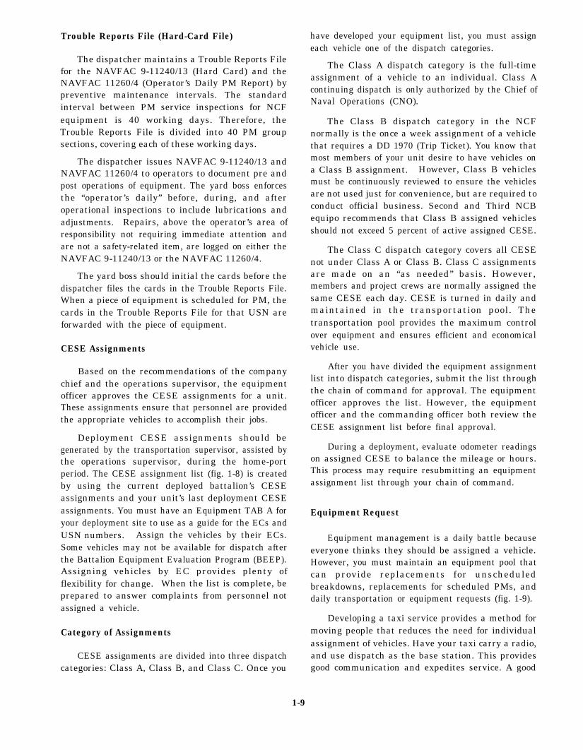
Trouble Reports File (Hard-Card File)
The dispatcher maintains a Trouble Reports Filefor the NAVFAC 9-11240/13 (Hard Card) and theNAVFAC 11260/4 (Operator’s Daily PM Report) bypreventive maintenance intervals. The standardinterval between PM service inspections for NCFequipment is 40 working days. Therefore, theTrouble Reports File is divided into 40 PM groupsections, covering each of these working days.
The dispatcher issues NAVFAC 9-11240/13 andNAVFAC 11260/4 to operators to document pre andpost operations of equipment. The yard boss enforcesthe “operator’s daily” before, during, and afteroperational inspections to include lubrications andadjustments. Repairs, above the operator’s area ofresponsibility not requiring immediate attention andare not a safety-related item, are logged on either theNAVFAC 9-11240/13 or the NAVFAC 11260/4.
The yard boss should initial the cards before thedispatcher files the cards in the Trouble Reports File.When a piece of equipment is scheduled for PM, thecards in the Trouble Reports File for that USN areforwarded with the piece of equipment.
CESE Assignments
Based on the recommendations of the companychief and the operations supervisor, the equipmentofficer approves the CESE assignments for a unit.These assignments ensure that personnel are providedthe appropriate vehicles to accomplish their jobs.
Deployment CESE assignments should begenerated by the transportation supervisor, assisted bythe operations supervisor, during the home-portperiod. The CESE assignment list (fig. 1-8) is createdby using the current deployed battalion’s CESEassignments and your unit’s last deployment CESEassignments. You must have an Equipment TAB A foryour deployment site to use as a guide for the ECs andUSN numbers. Assign the vehicles by their ECs.Some vehicles may not be available for dispatch afterthe Battalion Equipment Evaluation Program (BEEP).Assigning vehicles by EC provides plenty offlexibility for change. When the list is complete, beprepared to answer complaints from personnel notassigned a vehicle.
Category of Assignments
CESE assignments are divided into three dispatchcategories: Class A, Class B, and Class C. Once you
have developed your equipment list, you must assigneach vehicle one of the dispatch categories.
The Class A dispatch category is the full-timeassignment of a vehicle to an individual. Class Acontinuing dispatch is only authorized by the Chief ofNaval Operations (CNO).
The Class B dispatch category in the NCFnormally is the once a week assignment of a vehiclethat requires a DD 1970 (Trip Ticket). You know thatmost members of your unit desire to have vehicles ona Class B assignment. However, Class B vehiclesmust be continuously reviewed to ensure the vehiclesare not used just for convenience, but are required toconduct official business. Second and Third NCBequipo recommends that Class B assigned vehiclesshould not exceed 5 percent of active assigned CESE.
The Class C dispatch category covers all CESEnot under Class A or Class B. Class C assignmentsare made on an “as needed” basis. However,members and project crews are normally assigned thesame CESE each day. CESE is turned in daily andmaintained in the transportation pool. Thetransportation pool provides the maximum controlover equipment and ensures efficient and economicalvehicle use.
After you have divided the equipment assignmentlist into dispatch categories, submit the list throughthe chain of command for approval. The equipmentofficer approves the list. However, the equipmentofficer and the commanding officer both review theCESE assignment list before final approval.
During a deployment, evaluate odometer readingson assigned CESE to balance the mileage or hours.This process may require resubmitting an equipmentassignment list through your chain of command.
Equipment Request
Equipment management is a daily battle becauseeveryone thinks they should be assigned a vehicle.However, you must maintain an equipment pool thatcan provide replacements for unscheduledbreakdowns, replacements for scheduled PMs, anddaily transportation or equipment requests (fig. 1-9).
Developing a taxi service provides a method formoving people that reduces the need for individualassignment of vehicles. Have your taxi carry a radio,and use dispatch as the base station. This providesgood communication and expedites service. A good
1-9

Figure 1-8.—Sample deployment CESE assignments.
1-10

Figure 1-9.—Sample of a Vehicle/Equipment Request
1-11

taxi service reduces the number of membersrequesting an assigned vehicle.
Remember, one of your missions is to ensure themaximum service life of the equipment. This requiresmanaging the number of CESE dispatched andcontrolling the mileage placed on CESE.
YARD BOSS
The yard boss is your equipment yard supervisor.This is the key position in a successful equipmentmanagement program. The yard boss enforcesOperator Maintenance Procedures to reduceequipment breakdown.
The yard boss is responsible for the access, trafficflow, and condition of the equipment yard, therefueling facility, and supports the equipmentwashrack, the cycling and upkeep of equipment, anddaily transportation operations.
Tool Kit
Each Battalion Table of Allowance (TOA) in theNCF contains a Tool Kit, Kit 80111, for the Yard BossProgram. This kit provides the minimum tools andequipment resources necessary to support operatormaintenance. Operators requiring tools to performmaintenance should log out the tools through the yardboss.
Preventive Maintenance
The yard boss supports the PreventiveMaintenance (PM) Program by ensuring theequipment is cleaned, lubricated, and processedthrough collateral equipage. The yard boss receives aNAVFAC 9-11240/13 (Hard Card) from the dis-patcher who maintains a Hard Card log hook andissues a Hard Card number for tracking the mainte-nance of the equipment.
A recommended flow for PM Hard Cards is tohave the yard boss submit two Hard Cards stampedPM and initialed by the collateral equipmentcustodian. The equipment, Hard Card, and cardsfrom the Trouble Reports File for the USN are sent tothe mechanic equipment inspector. The mechanicinspector approves or rejects the equipment,depending on cleanliness and lubrication. Forequipment that is approved, the yard boss has themechanic inspector sign receipt of the Hard Cards andretains one for the dispatch records.
Equipment Cycling
The yard boss must be aware of equipment in theyard that is not regularly used. Equipment must beexercised to protect it from deterioration. All parts ofthe equipment must be operated at the rated capacityfor its intended use to constitute one completeperformance. Remember, starting and running theengine cycles the engine but not the equipment. Theyard boss must maintain a cycle log documentingdate, USN, duration equipment cycled, and anydeficiencies. Equipment must be maintained in astandby status and cycled on a weekly basis.
Washing of CESE
Part of the preventive maintenance program is thedaily cleaning of CESE that allows the detection andprevention of major problems. Dirt and grime canmake an engine run at excessive temperatures,increase fuel consumption, ruin hydraulic cylinders,corrode wiring, and destroy components.Additionally, dirt and grime can add over 1,000pounds of excess weight to an earthmover, clogradiators and possibly bring CESE to a grinding halt.Therefore, it is very important to REMEMBER thatdirt and grime cripples CESE performance andincreases operating costs.
The use of a high-pressure washer or steam iseffective means for removing the crusty, grittybuildup of dirt, grease, and grime from transmissions,track and roller assemblies, engine blocks, and drivetrains. The cleaning of equipment provides thefollowing results: extended equipment life; enhancedefficiency of mechanics when they performequipment inspections and repairs and increasedefficiency of operators when they perform pre andpost operational checks.
Thorough cleaning of equipment cannot beaccomplished with water alone. To provide aneffective wash program, the yard boss must maintaina supply of soap, brushes, rags, buckets, serviceablehoses, and a trash can at the washrack. Additionally,when manning allows, the yard boss should assign awashrack attendant to assist in maintaining wash rackoperations.
PM-to-Interim Repair Ratio
The PM-to-interim repair ratio is the number ofscheduled preventive maintemmce actions comparedto unscheduled maintenance actions (interim repairs).
1-12

The COMSECOND/COMTHIRDNCB equipo goalfor PM-to-interim repair ratio is three scheduled PMinspections to each interim repair. The yard bossprovides the first step toward meeting this goal byenforcing Operator Maintenance. Every operatormust keep assigned vehicles clean, safe, and inserviceable condition. Daily, operators should inspectthe following: fuel, oil, water, hydraulic fluids,battery levels, tires, lug nuts, lights, drive belts,mounted equipment, and exterior or interior damage.Operators must usc their sense of smell, sight, andfeel while operating equipment and note defects onthe Hard Cards.
An ideal Equipment Managment Programrequires the yard boss review all Hard Cards andNAVFAC 11260/4 forms for any deficiency. Fromthis review the yard boss determines if a repair shouldbe performed by the operator, evaluated by themechanic inspector, or to place the cards and forms inthe Trouble Reports File.
Sitting behind a desk is not the only job of atransportation supervisor. Be active! Scheduleyour work to ensure you are out in the yardduring prestart and post operations to reinforcethe Yard Boss Program. As the pool supervisor,you should review what CESE the yard boss issending to the shop for repairs that can impactthe PM-to-repair ratio. Discuss priority equip-ment problems with the operat ion andmaintenance supervisors. Remember, addingfluids, tightening belts, changing light bulbs, andlubricating are all operator maintenance. Dailycommunication between the pool supervisor,yard boss, and dispatcher concerning thecondition and availability of equipment is vital.As the transportation supervisor, you must alsocommunicate daily with the operations andmaintenance supervisors on the conditions of thetransportation pool.
Equipment Availability
Equipment availuability is the percentage of timethe equipment is available for dispatch compared todowntime. Equipment downtime is figured on a24-hour, 7-day-week basis. Ninety percent equip-ment availability is considered excellent, 85 percentis good, and 75 percent and below is poor.
The maintenance supervisoravailability. Overworked or
monitors equipmentabused equipment,
inadequate parts support, or shortage of mechanicsresult in poor equipment availability.
A strong Yard Boss Program is the key toincreased equipment availability and a decrease inequipment downtime.
COLLATERAL EQUIPAGE
The proper management of collateral equipagecan enhance a unit’s Equipment ManagementProgram. However, when this area is neglected, ahigh cost collateral equipage turnover can hinder anyeffective Equipment Management Program.
Maintenance supervisors are very concerned withcollateral equipage operations. Collateral equipmentaccountability is part of contingency readiness, andthe ordering of collateral equipment is the same asordering repair parts that are approved by themaintenance supervisor.
As the transportation supervisor, you shouldmake rounds of the collateral equipage area.Collateral equipage is divided into two basic types:component collateral equipage and tacticalcollateral equipage.
Component Collateral Equipage
Component collateral equipage consists ofitems, such as hoses for pumps and bits for the earthauger. These items are normally procured on thesame contract as the basic machine. The historyjacket should contain a list of the amount and types ofcomponent collateral equipage.
Tactical Collateral Equipage
Tactical collateral equipage consists of itemscommon to the equipment, such as top canvas andtarpaulin, bows and side racks, spare tire and rim,jack and lug wrench, and chains with hooks andbinders.
COLLATERAL EQUIPAGE CUSTODIAN
The collateral equipage custodian is a seasonedoperator who possesses an in-depth knowledge ofcollateral equip age terms, procedures, andequipment. The collateral equipage custodianmaintains a Collateral Custody Record Card,
1-13

Figure 1-10.—Collateral Custody Card, COMSECOND/COMTHIRDNCB 60 Form.
Figure 1-11.—Single-Line Item Consumption/Management Document (Manual), NAVSUP Form 1250-1.
1-14

COMSECOND/COMTHIRDNCB 60 Form (fig. 1- 10),for each line item of equipage for each unit of CESE.The equipage custodian enters all outstandingrequisitions, receipts, issues, locations, losses, andannotates the allowance of a particular line item ofequipage for each CESE on the CB 60 form.
The equipage custodian maintains the CB 60forms in folders for each USN-numbered CESE. TheCB 60 forms are pulled on the PM date to perform an
inventory of mounted or stored collateral equipage foreach USN-numbered CESE entering the shop. Theequipage custodian prepares a NAVSUP Form 1250-1(fig. 1-11) or a 1250-2 (fig. 1-12) for lost, damaged, ordeteriorated collateral equipment. Outstandingrequisitions, amount of gear on hand, and the dateinventoried are all on the CB 60 form. The inventoryprocedures are accountable man-hours on theEquipment Repair Order.
Figure 1-12.—Non-NSN Requisition, NAVSUP Form 1250-2.
1-15

The operators of Class B assignedCESE signs the CB 60 form assuming fullcustody of mounted collateral gear. CB 60forms for Class C mounted collateral gearon CESE are signed by the yard boss. Themounted collateral gear should beannotated on the daily (rip ticket, andcustody is assumed by the operator whosigns the trip ticket, or the collateralequipage can be issued and returned tocollateral each time the unit of CESE isdispatched.
ATTACHMENT CUSTODIAN
Attachments are accessories toconstruction equipment that enable thebasic equipment to perform its functionor adds versatility. Attachments arestored on handstands to keep the itemsout of sand, mud, and water. Hydrauliclines and fittings are sealed forprotection from dirt and moisture.
Attachment accessories, such asbucket teeth, sprockets, drum lagging, andwedges, are placed in boxes or on palletsand marked for the appropriate equipment.Wire rope, sheaves, and bolt threads arelubricated. Nuts and bolts are stored intheir respective holes on the attachmentswhen possible. Exposed machined surfacesand open parts are preserved to preventoxidation and damage. Storage ismaintained to ensure attachments belongingto one USN number are stored together.
The attachment custodian maintains acard file and log that provides anaccurate inventory of receipts and issuesof attachments, when the attachments werelast lubricated, and any damage incurredfrom one operation to another. Inaddition, the custodian is responsible for
the segregated storage of all attachmentsand their associated accessories.
The Attachments Status Board (fig.1-13) is maintained in the dispatcher’soffice by the attachment custodian. TheAttachments Status Board reflects theattachment code, NAVFAC identificationnumber, abbreviated description, the USNnumber of the equipment to which theattachment is assigned, the PM group (sameas the equipment the attachment isassigned), and location and remarks. Thecollateral equipage custodian usuallyperforms the duties of the attachmentcustodian.
FUEL OPERATIONS
The transportation pool manages allfuel operations. The Equipment Operator incharge of fuel operations must be mature,independent, and reliable. The abilitiesto communicate and to maintain logs arealso required. A poor fuel program resultsin needless downtime of equipment anddelays in production.
The fuel truck driver reviews theEquipment Status Board to determine thelocation of all CESE. The driver learnsthe fuel requirements and function of allequipment used on construction projects bycommunicating with the project crewleaders, the assigned Equipment Operator,and the transportation supervisor.
The fuel truck driver must beknowledgeable of all CESE. The driver mustavoid fueling with the wrong fuel orfilling hydraulic or cooling systems withfuel. Maintenance and transportationsuper-visors have fuel tanks stenciledwith the words MOGAS or DIESEL to avoidthis problem.
Figure 1-13.—Attachments Status Board.
1-16

The fuel truck driver must maintain accuraterecords of fuel issues, by equipment USN number, in alog. The driver also maintains records of bulk issues offuel for the tank truck and yard fuel pumps. The drivermust ensure fuel availability for contingency readiness,daily transportation, and construction operations.
The fuel truck driver maintains standards for the fueltanker according to COMSECOND/COMTHIRD-NCBINST 11200.1 Series. Vehicles used for bulktransport of gasoline, fuel, oil, or other flammableliquids are marked on both sides and the rear with theword FLAMMABLE in 6-inch black letters. The wordsNO SMOKING WITHIN 50 FEET is marked in 3-inchblack letters and numerals. A removable plate paintedblack with yellow letters to designate the liquid beingtransported is inserted in a 8-inch by 36-inch bracketthat is bolted on each side of the tanker. The plateshould have MOGAS painted on one side and DIESELpainted on the opposite side in 6-inch letters.
The fuel truck driver must maintain the fireextinguisher on the tanker truck. Second and ThirdNCB equipo recommends the guidelines set forth in theU.S. Army Corps of Engineers, Safety and HealthRequirements Manual, EM 385-1-1. At least oneportable fire extinguisher not less than 20-B:C units(20 = lbs, B = petroleum, C = electrical) shall beprovided on all tank trucks or other vehicles used fortransporting or dispensing flammable or combustibleliquids. The fire extinguisher must be securely mountedon the vehicle, properly filled, and located to ensure it isreadily accessible for use.
The fuel truck driver must have knowledge ofenvironmental pollution. Fueling operations mustalways be under controlled conditions and closelymonitored. Fuel spillage can be disastrous.
TRACTOR-TRAILER OPERATIONS
Tractor-trailer operations are managed by thetransportation supervisor. The hauling of equipment forthe Preventive Maintenance Program and the hauling ofconstruction supplies generates thousands of miles oftractor-trailer operations during a deployment.
The tractor-trailer drivers must be mature, reliable,and experienced. The hauling of oversized, heavy equip-ment is no job for inexperienced operators. For valuabletraining and future replacements, you should assign yourinexperienced operators with the experienced operators.
During the home-port period the operational paceslows and your crews lose an edge of professionalism. Youmust stay on top of all operations to ensure that oversized,heavy loads are handled by your best operators to avoid anymishaps. You must emphasize to your crews that when the
tractor-trailers are on the open rod they represent theU.S. Navy and the Seabees to the public.
As the transportation supervisor, you ensure yourtractor-trailer drivers adhere to the standards andprocedures set forth in the Commercial DriverLicense (CDL) Handbook for the state or states youoperate in. Height and width limitations are set byeach state, and you must obtain state permits to hauloversized loads. On deployment, you must obtain allrules and regulations for tractor-trailer operationsfrom the local department of motor vehicles and basesecurity. With the materials you obtain, develop aturnover folder for the next incoming battalion.
COMSECOND/COMTHIRDNCBINST 11200.1Series authorizes the use of operator nameplates.Nameplates are constructed of wood 3 1/2 inches highby 18 inches long; the wood is painted green with 2-inchhigh lettering painted glossy yellow. To increase prideof ownership and personal care, you should assign eachtractor-trailer driver a tractor-truck with theirnameplates centered on the front grille of the vehicle.
Chains and binders are collateral equipage for low-boytrailers. The chains and binders are maintained and issuedby the collateral equipage custodian. Depending on theamount of tractor-trailer operations, you may require allchains and binders checked out and returned on a dailybasis. Make the drivers accountable and responsible forissued collateral gear. Leaving chains and binders unused inthe storage compartment or on top of the trailer results inrust, excessive deterioration, or theft.
Cargo and equipment securing procedures are setforth in the Federal Motor Carrier Safety RegulationPocketbook. The aggregate static breaking strengthof tie-down assemblies used to secure an article mustbe at least 1 1/2 times the weight of that article.Chains used as tie-down assemblies must conform tothe requirements of the National Association of ChainManufacturer’s Welded and Weldless ChainSpecifications applicable to all types of chain.Binders used in conjunction with a tie-down assemblymust be equal to or greater than the minimumbreaking strength of the tie-down assembly.
The load on every vehicle must be distributed,chocked, tied down, or secured according to U.S.Army Corp of Engineers, Safety and HealthRequirements Manual, EM 385-1-1. It takes muchless time to tie down a load than it takes to report thereason a load fell off a trailer. After delivery of cargo,the driver should broom off all debris from the trailerto prevent possible damage to other vehicles or injuryto pedestrians during the return trip. The operator isresponsible for the safe operation of the tractor-trailerand the securing of cargo.
1-17

BUS SERVICE
To reduce the amount of CESE on the road,can deliver crews to jobsites by an establishedservice. Vehicle breakdowns, scheduled PMs,
youbusand
new construction tasking are times when a bus serviceis the best answer for transporting crews to jobsites.Jobsites having some type of communication shouldbe considered for bus service. Remember, remotejobsites require a safety vehicle. When bus service isused, construction materials can be delivered to thejobsite by the tractor-trailer crew. Crew vehicles mustbe monitored to ensure proper use. They are not to bejust a convenience for the crew leader.
The transportation supervisor manages the libertybus service. Assign mature, reliable equipmentoperators for this duty. During the predeploymentvisit, request the on-site deployed unit’s liberty buspolicy and schedule. This policy and scheduleprovides you and the operations supervisorinformation to use to generate a liberty bus policy foryour unit. The equipment officcr, company chief, andmaintenance supervisor evaluate and preapprove thepolicy. The commanding officer has the finalapproval and must sign the policy into effect. The busservice is for the troops; ensure you establish a busroute that accommodates their needs.
MAINTENANCE FIELD CREWOPERATIONS
Dispatchers are the hub of communications fortrouble calls for CESE in the field. The success of adeployment from an equipment maintenance andproject completion standpoint can be traced to theavailability of equipment due to the field maintenancecrew’s ability to perform adequate and timely repairsin the field. The field maintenance crew reduces theequipment shop work load by repairing CESE in thefield. The dispatchers maintain a log to track the flowof field repairs and inform the heavy shop supervisorof any trouble calls. The equipment heavy shopsupervisor controls the field maintenance crewoperations. The maintenance held crew must dailyinform the dispatchers of the status of repairs made toCESE. The extent of damage on the CESE mightrequire shop repairs. The dispatcher should schedulethe hauling of the CESE to the shop and schedulepossible CESE replacement. The dispatcher mustinform you of all actions and update the field crewrepair log.
EQUIPMENT MAINTENANCEPROGRAM
At all times, the goal of the Equipment MaintenanceProgram is to keep all CESE in a safe and serviceablecondition at a reasonable cost and to detect minordeficiencies before they develop into costly repairs.
MAINTENANCE SUPERVISOR
The maintenance supervisor is normally the seniormechanic responsible for the maintenance program forall assigned CESE. The maintenance supervisorsupervises the inspectors, shop super- visors, preventivemaintenance and cost control clerks, technical librarian,and the part’s expeditor. Additionally, this position isresponsible for enforcing all established maintenancepolicies, approving all repair actions and requisitions,controlling all CESE transfers and disposal, supervisingthe Preventive Maintenance Program, and controllingall mechanics, shop tools, and kits.
The maintenance supervisor coordinates closelywith the operations supervisor on all equipmentrequirements, equipment abuse, and reoccurringequipment breakdowns.
Inspector
The equipment inspector is a knowledgeable andproficient senior Construction Mechanic, preferably aCM1, capable of readily determining the nature of thenecessary repairs on any piece of equipment. Theinspector exercises independent judgment as towhether the equipment requires immediate attentionor can be delayed until the scheduled PM. Whenrepairs are required, the inspector must have theability to describe each repair action clearly on theEquipment Repair Order (ERO), NAVFAC 11200/41.After performing a final inspection and determiningthat repairs have been satisfactorily completed andthe equipment is ready for full service, the equipmentinspector should take the ERO and the equipment todispatch for customer approval and the signing ofBlock 77 of the ERO. The ERO is then returned tocost control for final closing.
Preventive Maintenance (PM)/Cost ControlClerk(s)
Working directly for the maintenance supervisor,the PM/cost control clerk divides all CESE intopreventive maintenance (PM) groups, prepares thePM schedule, and maintains the PM Record Card,NAVFAC 11240/6 (fig. 1-14), with the preventive
1-18

ASSIGNED TO PHONE TYPE OF EQUIP CODE JOB ORDER NO. PM GROUPASSIGNMENT
NMCB 423001 13
NAME MODEL TYPE YEAR EST. ANNUAL MI/HRS USN REG. NO.
BUCYRUS ERIE 30B D 82 42-03317
CUMULATIVE MILES (OR HRS) MILES (OR HRS) CUMULATIVE MILES (OR HR) MILES (OR HR)TYPE DATE MILEAGE OR SINCE REPORTED FOR TYPE DATE MILEAGE OR SINCE REPORTED FOR PM HRS. OPN. LAST PM 6 MO. PERIOD PM HRS. OPN. LAST PM 6 MO. PERIODLAST
A 2-4-88 1945 ENTRIESLAST TRANSLATED
B 6-5-88 2259 FROMLAST PRIOR
C 4-1-88 2060 RECORD
07 6-1-88 210001 7-26-88 215601 9-21-88 234002 11-16-88 2510 O/C,F/C,FF/C,HF,C
VEHICLE/CONSTRUCTION EQUIPMENT PM RECORD NAVFAC 11240/6 (2 75) SUPERSEDES NAVDOCKS 1949
TYPE CUMULATIVE MILES (OR HRS) MILES (OR HRS) CUMULATIVE MILES (OR HR) MILES (OR HR) PM DATE MILEAGE OR SINCE REPORTED FOR TYPE DATE MILEAGE OR SINCE REPORTED FOR HRS. OPN. LAST PM 6 MO. PERIOD PM HRS. OPN. LAST PM 6 MO. PERIOD
A14000 FAIRLEAD 1
A04000 BOOM TIP 1
A03500 BOOM JIB 1
A02500 BOOM BUTT 1
A11500 CRANE HOOK 1
A03000 BOOM EXT 3
A23500 TAG LINE 1
NAVFAC 11240/6 (2-75) BACK *U.S. GOVERNMENT PRINTING OFFICE 1980-603-189/6831 2-1
Figure 1-14.—Sample of Vehicle/Construction Equipment PM Record, NAVFAC 11240/6.
1-19
}
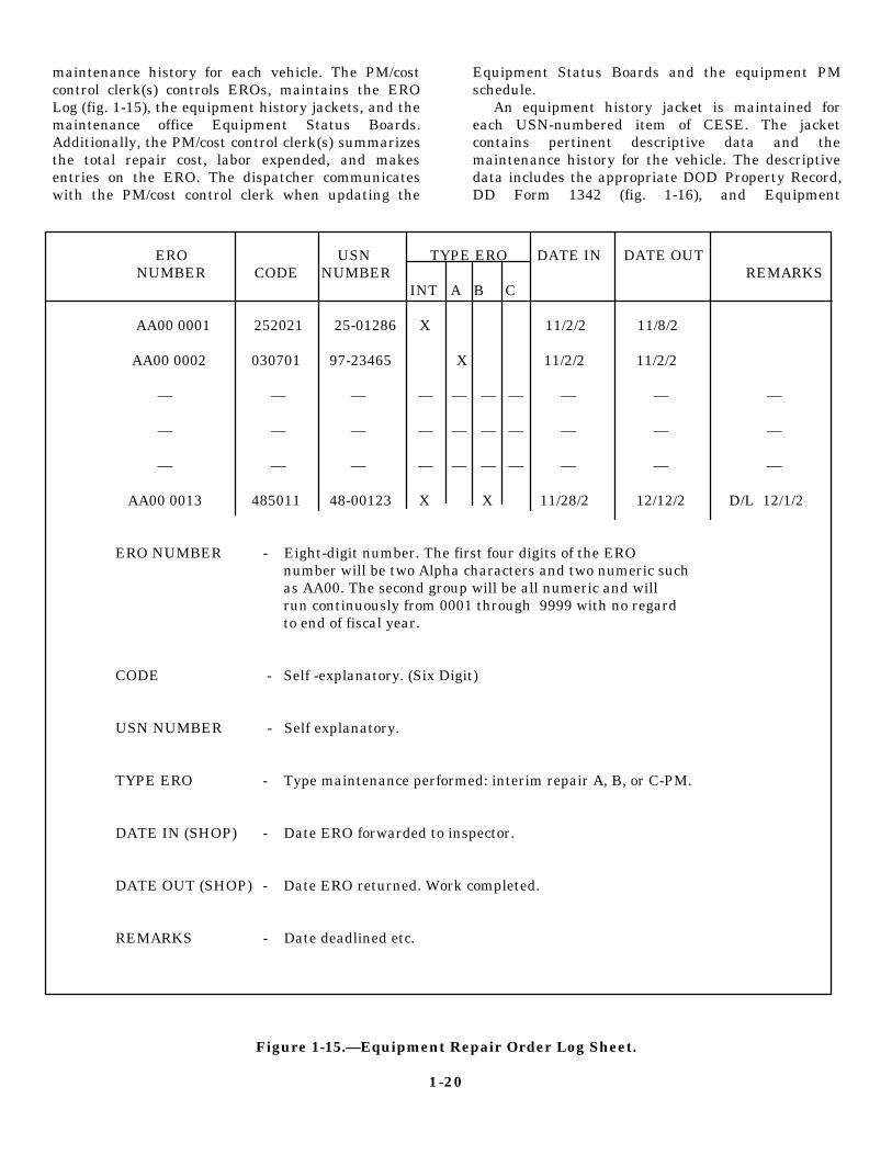
maintenance history for each vehicle. The PM/costcontrol clerk(s) controls EROs, maintains the EROLog (fig. 1-15), the equipment history jackets, and themaintenance office Equipment Status Boards.Additionally, the PM/cost control clerk(s) summarizesthe total repair cost, labor expended, and makesentries on the ERO. The dispatcher communicateswith the PM/cost control clerk when updating the
Equipment Status Boards and the equipment PMschedule.
An equipment history jacket is maintained foreach USN-numbered item of CESE. The jacketcontains pertinent descriptive data and themaintenance history for the vehicle. The descriptivedata includes the appropriate DOD Property Record,DD Form 1342 (fig. 1-16), and Equipment
ERO USN TYPE ERO DATE IN DATE OUTNUMBER CODE NUMBER REMARKS
INT A B C
AA00 0001 252021 25-01286 X 11/2/2 11/8/2
AA00 0002 030701 97-23465 X 11/2/2 11/2/2
— — — — — — — — — —
— — — — — — — — — —
— — — — — — — — — —
AA00 0013 485011 48-00123 X X 11/28/2 12/12/2 D/L 12/1/2
ERO NUMBER - Eight-digit number. The first four digits of the ERO number will be two Alpha characters and two numeric such
as AA00. The second group will be all numeric and will run continuously from 0001 through 9999 with no regard to end of fiscal year.
CODE - Self -explanatory. (Six Digit)
USN NUMBER - Self explanatory.
TYPE ERO - Type maintenance performed: interim repair A, B, or C-PM.
DATE IN (SHOP) - Date ERO forwarded to inspector.
DATE OUT (SHOP) - Date ERO returned. Work completed.
REMARKS - Date deadlined etc.
Figure 1-15.—Equipment Repair Order Log Sheet.
1-20

Figure 1-16.—DoD Property Record, DD Form 1342
1-21

Figure 1-17.—Equipment Attachment Registration Record, NAVFAC 6-11200/45.
Attachment Registration Record, NAVFAC 6-l1200/45 (fig. 1-17), when applicable. Thehistory jacket also includes the completedPM record cards and the blue copies ofcompleted EROs. EROs relating toacceptance checks, PMs, accident reports,speedometer or hour meter replacement, andall repair records are retained in thehistory jacket for the life of theequipment. When a vehicle is transferred,the PM record card is removed from the PMgroup file and returned to the historyjacket. The jacket is hand carried orforwarded by certified mail to thereceiving custodian. The history jacketshould accompany a vehicle when it istransferred to a property disposal office.
Direct Turnover Clerk
The direct turnover (DTO) clerkmaintains the maintenance shop’s repairparts status and accountability recordsand is the liaison between the supplyoffice and the shop. All requisitions fornot in stock (NIS) and not carried (NC)materials must pass through the DTO clerkwho maintains the DTO Log (fig. 1-18). TheDTO clerk receives DTO parts and storesthem by USN in PM groups and notifies thecost control clerk of parts received.
The DTO room is a secured area largeenough to contain forty 12-inch by 12-inch cubes labeled with a
Figure 1-18.—Direct Turnover (DTO) Log.
1-22
PM group. When DTO parts are received, they mustbe placed in the cube that corresponds to the PMgroup of the equipment requiring the parts.
Technical Librarian
Technical librarians are responsible for theprepacked library consisting of operational,maintenance, and part’s manuals. They establish andenforce check-out procedures for manuals and initiateparts requisitions on NAVSUP Form 1250s. The taskof researching and preparing the 1250s is normallyhandled by the technical librarian to free the floormechanics to perform maintenance functions.
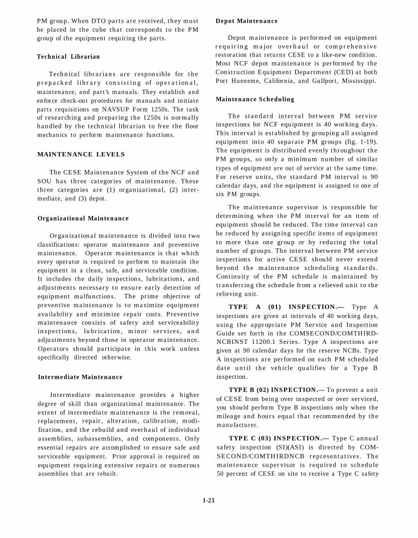
MAINTENANCE LEVELS
The CESE Maintenance System of the NCF andSOU has three categories of maintenance. Thesethree categories are (1) organizational, (2) inter-mediate, and (3) depot.
Organizational Maintenance
Organizational maintenance is divided into twoclassifications: operator maintenance and preventivemaintenance. Operator maintenance is that whichevery operator is required to perform to maintain theequipment in a clean, safe, and serviceable condition.It includes the daily inspections, lubrications, andadjustments necessary to ensure early detection ofequipment malfunctions. The prime objective ofpreventive maintenance is to maximize equipmentavailability and minimize repair costs. Preventivemaintenance consists of safety and serviceabilityinspections, lubrication, minor services, andadjustments beyond those in operator maintenance.Operators should participate in this work unlessspecifically directed otherwise.
Intermediate Maintenance
Intermediate maintenance provides a higherdegree of skill than organizational maintenance. Theextent of intermediate maintenance is the removal,replacement, repair, alteration, calibration, modi-fication, and the rebuild and overhaul of individualassemblies, subassemblies, and components. Onlyessential repairs are accomplished to ensure safe andserviceable equipment. Prior approval is required onequipment requiring extensive repairs or numerousassemblies that are rebuilt.
Depot Maintenance
Depot maintenance is performed on equipmentrequiring major overhaul or comprehensiverestoration that returns CESE to a like-new condition.Most NCF depot maintenance is performed by theConstruction Equipment Department (CED) at bothPort Hueneme, California, and Gulfport, Mississippi.
Maintenance Scheduling
The standard interval between PM serviceinspections for NCF equipment is 40 working days.This interval is established by grouping all assignedequipment into 40 separate PM groups (fig. 1-19).The equipment is distributed evenly throughout thePM groups, so only a minimum number of similartypes of equipment are out of service at the same time.For reserve units, the standard PM interval is 90calendar days, and the equipment is assigned to one ofsix PM groups.
The maintenance supervisor is responsible fordetermining when the PM interval for an item ofequipment should be reduced. The time interval canbe reduced by assigning specific items of equipmentto more than one group or by reducing the totalnumber of groups. The interval between PM serviceinspections for active CESE should never extendbeyond the maintenance scheduling standards.Continuity of the PM schedule is maintained bytransferring the schedule from a relieved unit to therelieving unit.
TYPE A (01) INSPECTION.— Type Ainspections are given at intervals of 40 working days,using the appropriate PM Service and InspectionGuide set forth in the COMSECOND/COMTHIRD-NCBINST 11200.1 Series. Type A inspections aregiven at 90 calendar days for the reserve NCBs. TypeA inspections are performed on each PM scheduleddate until the vehicle qualifies for a Type Binspection.
TYPE B (02) INSPECTION.— To prevent a unitof CESE from being over inspected or over serviced,you should perform Type B inspections only when themileage and hours equal that recommended by themanufacturer.
TYPE C (03) INSPECTION.— Type C annualsafety inspection (SI)(ASI) is directed by COM-SECOND/COMTHIRDNCB representatives. Themaintenance supervisor is required to schedule50 percent of CESE on site to receive a Type C safety
1-23

Figure 1-19.—Sample of Preventive Maintenance Schedule.
1-24

inspection, using the appropriate PM Service andInspection Guide. The relieving maintenancesupervisor is required to schedule the other 50 percentof CESE on site. The Type C inspection is performedon a scheduled PM date that least effects operationalcommitments.
The Naval Construction Force (NCF) PM Serviceand Inspection Guide is outlined in the NavalConstruction Force Equipment ManagementManual, NAVFAC P-404, and Equipment Manage-ment, COMSECOND/COMTHIRDNCBINST11200.1 Series.
Repair Parts
The NAVFAC repair parts allowance required fora NCF unit’s assigned organic and augmentequipment is contained in the Consolidated SeabeeAllowance List (COSAL). These repair parts arefunded by NAVFAC. COSALS are published underthe authority contuined in the NAVFAC or NAVSUPprogrtim support agreement by Navy Ships PartsControl Center (SPCC), Mechanicsburg.
COSALS.— COSALS are both technical andsupply documents. They are technical documents inthat equipment nomenclature, operatingcharacteristics, technical manuals, and so forth, aredescribed in the Allowance Parts Lists. They aresupply documents because they list all parts bymanufacturer’s code and part number, national stocknumber, unit of issue, price and quantity authorizedby NAVFAC maintenance policy. Repair partsallowances are designed to provide a 90 percenteffectiveness for 1,800 construction hours or 90 dayssupport. The 90-day period is defined as a 3-monthutilization period for CESE in new or like-newcondition.
CATEGORIES.— Repair parts are divided intotwo basic categories: parts peculiar, NAVSUPmodifier code 98, and parts common, NAVSUPmodifier code 97. These are published in twoseparate COSALS. Parts peculiar are applicableonly to specific makes or models of equipment. Partscommon are general repair type of items and are notreferenced to any specific equipment. Military andcommercial operator’s manuals, parts manuals, andmaintenancee manuals are listed in the parts peculiar toa COSAL. A descriptive accout showing the methodof entry and how to usc the COSAL is contained inappendix F of the COSAL instruction.
The third category of repair parts is the NAVSUPmodifier code 98. The mod 96 is a minimodifier 97for use with an air detachment or an extended
detachment without jeopardizing the main body. Themod 96 repair parts allowance is designed to provide90 days support.
Equipment Repair Order
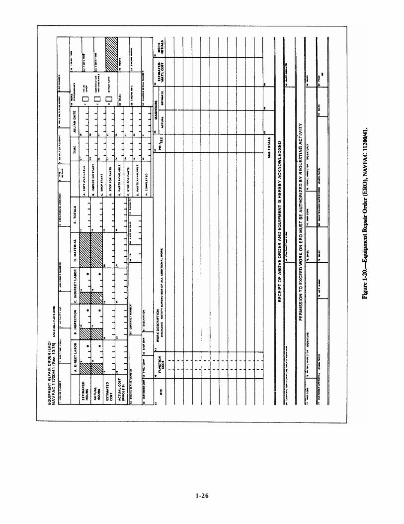
The Equipment Repair Order (ERO), NAVFAC11200/41 (figs. 1-20 and 1-21), and the EROContinuation Sheet, NAVFAC 11200/41A (fig. 1-22),are used in the NCF to record cost of repairs, hoursrequired for repairs, and total time that equipment isout of service. The ERO data help the NCF in budgetplanning, determining life expectancies of equipment,and predicting future equipment and trainingrequirements. The Civil Engineer Support Office,Port Hueneme, California, uses the data to compilecost and utilization figures on each piece ofUSN-numbered equipment.
The ERO Continuation Sheet is used with theERO when the number of repair items exceed thespaces provided on the ERO. The Equipment RepairOrder (ERO) Work Sheet, NAVFAC 11200/41B(fig. 1-23), is used on site to record repair parts useand is filed with the complete ERO in the equipmenthistory jacket.
The ERO is the sole authority to perform work onequipment regardless of whether the work isperformed in the field or in the shop. An ERO isrequired each time labor exceeds 1 hour or materialsare expended on scheduled PM, interim repairs,modernization or alteration of equipment, or deadlinecycling or preservation of equipment. The EquipmentRepair Order Log Sheet (fig. 1-15) is used to track thestatus of the EROs.
LIVE STORAGE PROGRAM
The Naval Construction Battalions deployed atmain body sites are assigned numerous pieces ofCESE to support contingency, emergency, andpeacetime construction operations. Peacetimeconstruction operations do not require the use of thefull allowance of CESE that results in a number ofpieces being placed in extended periods ofnonutilization. This equipment absorbs maintenanceman-hours, deteriorates, and could possibly beimproperly used.
The maintenance supervisor controls the LiveStorage Program developed to reduce maintenancehours spent on CESE. The Live Storage Branch isadequately staffed with skilled, experiencedmechanics and equipment operators.
1-25
1-26

1-27

1-28

1-29

CESE is placed in live stortigc when there is noplanned need for it for a period covering two PMcycles or 80 working days. CESE eligible for livestorage must have an equipment evaluation code ofA5 or above. All cranes are maintained in an activestatus and are under the control of the crane crew. Tobalance CESE through mileage or hours utilization,you should review low-mileage stored CESE forpossible rotation with high-mileage active CESE withlike equipment codes (EC).
All Equipment Status Boards must denote CESEthat is assigned to live storage. The CESE in livestorage is not for replacement of vehicles that are inthe shop for PM or repairs. Live storage proceduresare outlined in the Naval Construction ForceEquipment Management Manual, NAVFAC P-404,the Live Storage of CESE, C O M S E C O N D /COMTHIRDNCBINST 11200.9 series, and theMaintenance of Active CESE at MainbodyDeployment Sites, COMSECOND/COMTHIRD-NCBINST 11200.22 Series.
STORAGE OF PETROLEUM PRODUCTS
Bulk petroleum products are stored, inventoried,and issued by the battilion supply department, andfuel products are stored in the Alfa company yard.The maintenance supervisor maintains enough oil andlubricate supply in the mechanic’s shop to performmaintenance operations.
The transportation supervisor is responsible forthe storage of petroleum products used in thetransportation pool. Storing petroleum productsincludes taking steps to prevent fires, watercontamination, and ground pollution. Guidelines forstorage and issue of flammable and combustibleliquids are found in the U.S. Army Corps ofEngineers, Safety and Health Requirements Manual,EM385-1-1.
EQUIPMENT ACQUISITION ANDDISPOSITION
Equipment acquisition and disposition proceduresfor public works units are found in NAVFAC P-300.Second and Third NCB equipo offices notifybattalions of equipment acquisition or equipmentdisposition instructions by message traffic. Theprocedures are found in the COMSECOND/COMTHIRDNCBINST 11200.1 Series. CivilEngineer Support Office (CESO) handles theacquisition and disposition of CESE for specialoperation units (SOUs).
BEEP
The purpose of the Battalion EquipmentEvaluation Program (BEEP) is to use the fullexpertise and efforts of the two equipment forces toprovide the relieving battalion the best possibleturnover of Alfa company operations. Additionally,pass on all special knowledge of CESE maintenance,operation techniques, and provide a realistic in-depthcondition evaluation of CESE allowance, facilities,tools, and materials.
The maintenance supervisor provides thetransportation supervisor the scheduled CESE list forthe BEEP. COMSECOND/COMTHIRDNCBINST11200.1 Series recommends that CESE scheduling beaccomplished by PM groups, with the appropriatenumber of groups scheduled each day to complete theBEEP within 10 working days. The 10 working dayscovers the cleaning, inspection, hands-on work, andfinal inspection of all CESE, and turnover ofcollateral equipage, tool kits, and other Alfacompany-related areas.
BEEP preparation occurs the same time thebattalion is preparing for the turnover of the SeabeeCamp and construction projects. The equipment poolmust have enough CESE cleaned and staged beforecommencement of the BEEP to ensure full use of allmechanics for 2 complete workdays. This requires aCESE assignment adjustment and the dispatching ofCESE on a priority basis.
The Alfa company operation and maintenancesupervisors generate a BEEP assignment list usingthe guidelines found in the COMSECONDCOM-THIRDNCBINST 11200.1 Series. Additionally, youneed to develop a wash, grease, and CESE inspectioncrew to support the preparation of the CESE. Theoperator’s maintenance performed at these stationsprovides expeditious flow of CESE as it goes throughthe mechanic shop.
Second and Third NCB equipo o f f i cerepresentatives conduct a counterparts meeting beforethe commencement of the BEEP to set the proceduresand guidelines for the BEEP. The representativesprov ide technica l ass is tance and ho ld acomprehensive inspection on the overall effectivenessof the relieved battalion’s equipment managementprogram. Additionally, they conduct a randominventory of repair parts stock to determine theaccuracy of the existing inventory, conduct a critiqueupon the completion of the BEEP, and prepare andsubmit a BEEP completion report (fig. 1-24) toSecond and Third NCB with copies to appropriateinformation addressees.
1-30
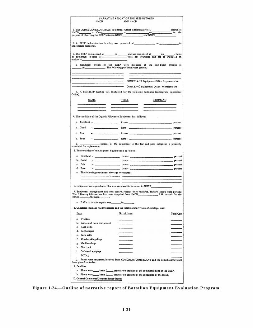
Figure 1-24.—Outline of narrative report of Battalion Equipment Evaluation Program.
1-31
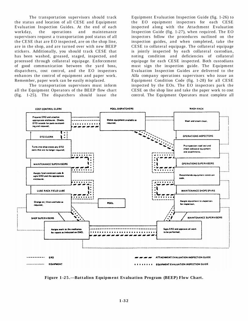
The transportation supervisors should trackthe status and location of all CESE and EquipmentEvaluation Inspection Guides. At the end of eachworkday, the operations and maintenancesupervisors request a transportation pool status of allthe CESE that are EO inspected, are on the shop line,are in the shop, and are turned over with new BEEPstickers. Additionally, you should track CESE thathas been washed, greased, staged, inspected, andprocessed through collateral equipage. Enforcementof good communication between the yard boss,dispatchers, cost control, and the EO inspectorsenhances the control of equipment and paper work.Remember, paper work can be easily misplaced.
The transportation supervisors must informall the Equipment Operators of the BEEP flow chart(fig. 1-25). The dispatchers should issue the
Equipment Evaluation Inspection Guide (fig. 1-26) tothe EO equipment inspectors for each CESEinspected along with the Attachment EvaluationInspection Guide (fig. 1-27), when required. The EOinspectors follow the procedures outlined on theinspection guides, and when completed, take theCESE to collateral equipage. The collateral equipageis jointly inspected by each collateral custodian,noting condition and deficiencies of collateralequipage for each CESE inspected. Both custodiansmust sign the inspection guide. The EquipmentEvaluation Inspection Guides are delivered to theAlfa company operations supervisors who issue anEquipment Condition Code (fig. 1-28) for all CESEinspected by the EOs. The EO inspectors park theCESE on the shop line and take the paper work to costcontrol. The Equipment Operators must complete all
Figure 1-25.—Battalion Equipment Evaluation Program (BEEP) Flow Chart.
1-32

Figure 1-26A.—Equipment Evaluation Inspection Guide (Front).
1-33

Figure 1-26B.—Equipment Evaluation Inspection Guide (Back).
1-34

Figure 1-26B.—Equipment Evaluation Inspection Guide (Back)—Continued.
CESE inspections 2 or 3 days before the plannedBEEP completion date, ensuring that all CESE isprocessed through the mechanic shop.
Mechanic inspectors conduct BEEPinspections using the Equipment EvaluationInspection Guide. A safety inspection EquipmentRepair Order (ERO) is developed for all CESEassigned. Any discrepancies listed on the evaluationguide is transferred to an ERO for repairs. Maintenancesupervisors determine what repairs can be accomplishedbased on the work force, space, and repair partsavailable. Additionally, they inspect all maintenancerecords, review and account for all maintenancecorrespondence, and inventory and inspect allpermanent Alfa company shop equipment. Themaintenance supervisors review all the EquipmentEvaluation Inspection Guides and approve allEquipment Condition Codes (fig. 1-28) for each CESE.
After the final inspections of all CESE, themechanics place NMCB unit identification markingdecals (red-diamond shape for organic equipment andwhite-diamond shape for augment allowanceequipment) in the correct locations. The dispatchersigns Block 77 of the EROs for customer approval ofall CESE “BEEPed.”
COMSECOND or COMTHIRD equipo reviewsand approves all BEEP equipment evaluation guidesand EROs. At the completion of all Alfa companyinspections, the relieving equipment officer signs theTAB A as acceptance of the equipment for therelieving battalion.
LICENSE PROGRAM
A properly administered license program ensuresonly thoroughly trained personnel who are physically
1-35

Figure 1-27.—Attachment Evaluation Inspection Guide.
1-36

Figure 1-28.—Equipment Condition Codes.
and mentally qualified are licensed as EquipmentOperators.
LICENSE EXAMINER
The license examiner should be the bestqualified licensed equipment operator available. Thelicense examiner is appointed by letter by thecommanding officer and has the responsibility tobecome familiar with and maintain a library of thefollowing publications:
1. Storage and Materials Handling,DODINST 4145.19-R-1
2. Motor Vehicles Management Acquisitionand Use, OPNAVINST 11240.16A Motor
3. Vehicles Driver’s Handbook, NAVSEAOP-2239, and Ammunition, Explosives,and Related Hazardous Materials
4. Management of TransportationEquipment, NAVFAC P-300
5. Testing and Licensing of ConstructionEquipment Operators, NAVFAC P-306 6.
6. Management of Weight-HandlingEquipment Maintenance andCertification, NAVFAC P-307
7. Navy Driver’s Handbook, NAVFAC MO-403
8. Naval Construction Force EquipmentManagement Manual, NAVFAC P-404
9. Naval Construction Force Safety Manual,COMSECOND/COMTHIRDNCBINST Series
10. Federal Motor Carrier Safety Regulations,Parts 390-397
Additionally, the license examiner maintainsa license file under lock and key for each licensedoperator in the command. These files aremaintained to provide information on the types ofequipment the operator is qualified to operate,applicants background and experience,examination findings, special requirements, trafficviolations, and accident history. The licenseexaminer must comply with the Privacy Act of 1974in the maintenance of all files of licensed operators.The license examiner maintains a tickler file ofeach operator’s license expiration date and ensuresall personnel are properly trained on the equipmentbefore issuing the Operator’s
1-37

Figure 1-29.—Operator’s Identification Card, OF-346.
Identification Card, OF-346 (fig. 1-29), or Con-struction Equipment Operator License, NAVFAC 11260/2 (fig. 1-30).
APPLICATION FORMS
The proper form used when applying for anautomotive or material-handling equipment license isthe Application for Vehicle Operator’s IdentificationCard, NAVFAC 11240/10 (figs. 1-31 and 1-32). Theproper form to use when applying for a license forconstruction equipment is the Application forConstruction Equipment Operator License, NAVFAC11260/1 (figs. 1-33 and 1-34). All application forms arecompleted by the applicants and signed by thecompany commander or company chief. The NAVFACP-300 states “Military personnel may operategovernment-owned or leased vehicles under 10,000pounds GVW without a government license.”However, all personnel in the NCF and specialoperating units (SOUs) who operate government-owned or rented equipment under the maintenancemanagement policy of the NAVFAC P-404 shall bequalified and have in possession a valid U.S.government operator’s license, covering the size andtype of vehicle to be operated.
PHYSICAL FITNESS INQUIRY FORM
Applicants for the U.S. Government MotorVehicle Operator’s Identification Card, OF-346 (fig. 1-29), and the Construction Equipment OperatorLicense, NAVFAC 11260/2 (fig. 1-30), are required tocomplete a Physical Fitness Inquiry for Motor VehicleOperators, Standard Form 47 (fig. 1-35). The license
Figure 1-30.—Construction EquipmentOperator License, NAVFAC 11260/2.
1-38

Figure 1-31.—Application for Vehicle Operator’s Identification Card, NAVFAC 11240/10 (Front).
1-39

Figure 1-32.—Application for Vehicle Operator’s Identification Card, NAVFAC 11240/10 (Back).
1-40
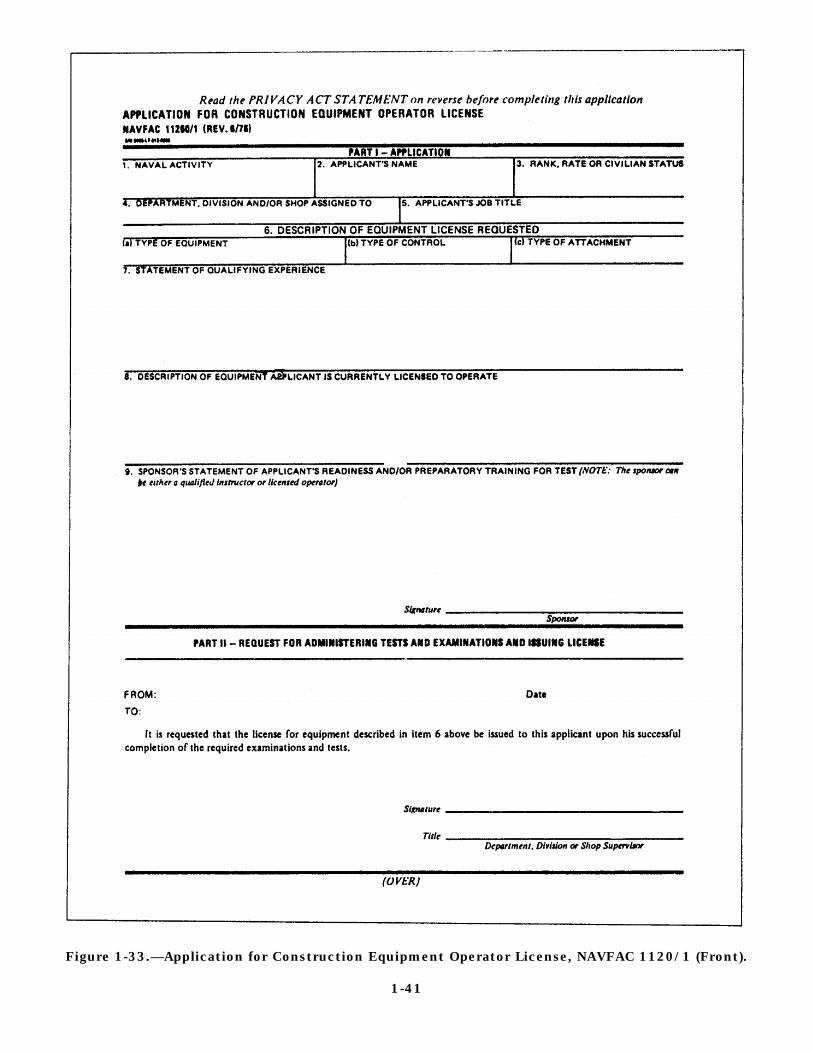
Figure 1-33.—Application for Construction Equipment Operator License, NAVFAC 1120/1 (Front).
1-41

Figure 1-34.—Application for Construction Equipment Operator License, NAVFAC 11260/1 (Back).
1-42

Figure 1-35.—Physical Fitness Inquiry for Motor Vehicle Operators, Standard Form 47.
1-43

examiner reviews and evaluates this form and otheravailable information regarding the physicalcondition of the applicant and determines if a physicalexamination is required. Operators must have nophysical defects or emotional instability that renderthem a hazard to themselves or others. The medicaldepartment conducts all physical examinations ofapplicants referred by the licensing examiner, and theresults arc recorded in the appropriate portion of theapplication form. The SF-47 is retained in theapplicant file and replaced with a new one each timethe license is renewed or upon request of the licenseexaminer. Physical examinations are required foropertators assigned to transport explosives.
LICENSE TEST
Applicants must pass a written examinationbefore taking the performance qualification tests.The written test is based on traffic laws andregulations, accident reporting procedures, operator’smaintenance responsibilities, safe driving practices,and the characteristics and limitations of the types ofequipment for which the test is being given.information particular to a piece of equipment isobtained from the operator's manual located in theTechnical Library.
Written examination questions are prepared bythe license examiner and are approved by theequipment officer and at least two written tests shouldbe developed for each type of equipment. Writtenexaminations, blank license, and answer sheets arestored in a secure location under lock and key.Numerous sample written tests for construction andweight-handling equipment are contained in theTesting and Licensing of Construction EquipmentOperators, NAVFAC P-306. Applicants should studythe operator’s manual when preparing for written andperformance examinations.
Examinations and tests for military personnelapplying for a license to operate general-purposevehicles up to 10,000 pounds GVW is normallywaived if the applicant possesses a valid stateoperator’s license for the type vehicle involved.
Performance Qualification Tests
All performance qualification tests (excludingcranes) must be given by the license examiner. Allapplicants who pass the written test must successfullypass an operational performance or road test and per-form pre and post operational operator maintenance,
as outlined in the operator’s manual. The per-formance qualification test enables a qualifiedexaminer to evaluate the operating skills of eachapplicant. The examiner must terminate anyperformance test that becomes hazardous or when anapplicant demonstrates a lack of skill, unduenervousness, speeding, inattentiveness, or otherunfavorable actions. Personnel failing to qualify for alicense should not be reexamined until after furthertraining or instruction. The specific reason for failureis noted on the application and filed in the license fileof the applicant.
Automotive Tests
Applicants for an OF-346 must pass a locallycreated driver skill test before being given a road testto determine their reactions under varying trafficconditions. The road test is administered in thelargest capacity vehicle for which the license is to beissued. A locally devised checklist that reflects therequirements for the local conditions is used for theevaluation.
Materials-Handling Equipment Tests
Applicants for the materials-handling equipment(MHE) license are operationally tested and scored asprescribed in Storage and Materials Handling,DODINST 4145.19-R-1. This publication containssample MHE test questions.
Construction Equipment Tests
Applicants for a NAVFAC 11260/2 license mustbe familiar with the standard Navy hand signalsbefore taking a performance qualification test. Awide variety of construction and weight-handlingequipment is used by the Navy. For this reason,standard Navy-wide performance qualification testsare not practical; therefore, the local examiner mustprepare such operational tests as required. Numeroussamples of operational tests are contained in theNAVFAC P-306.
LICENSE FORMS
After an applicant satisfactorily completes all therequired tests, the examiner issues a license that listseach type of vehicle the license holder is authorized tooperate. Any restrictions imposed on the license arealso listed.
1-44

U.S. Government Motor Vehicle Operator’sIdentification Card, OF-346
The OF-346 is the license required for automotivemotor vehicles and material-handling equipment.Possession of a valid state operator’s license is notrequired for the issuance of an OF-346 to militarypersonnel on active duty. However, an OF-346 and avalid state driver’s license are required to operategovernment-owned or rented vehicles or equipmentoff base in Alaska, Massachusetts, Nebraska,Missouri, New Hampshire, New Jersey, New York,Connecticut, Vermont, and the District of Columbia.
A properly completed and valid OF-346 musthave the following entries:
1. Card number: A two-part sequential numberthat is the actual license number. The first part of thenumber is the activity number or unit designation ofthe original license issuing activity. The second partof the number is the appropriate sequential number inorder of issue. Example: NMCB-3 license number88 becomes 3-88; a 31ST NCR license numberbecomes 31-88. This number is indicated on theoperator’s record, NAVFAC 11240/10, or NAVFAC11260/3, Construction Equipment Operator LicenseRecord (fig. 1-36). The license examiner maintains achronological record of all licenses issued.
2. Restrictions: Physical limitations and restric-tions. Typical notations are glasses, daytime, hearingaid, or learner.
3. Types of vehicle or equipment: A descriptionof equipment the operator is qualified to operate.Each separate item does not have to be listed; usenotations like trucks through 1 1/4 tons, tractor andtrailer through 10 tons, and so forth.
4. Capacity: See Item 3.
5. Qualifying official: Signature of examiner.
6. Other records: This section is used for a typeof license that requires specific notation. Examplesare as follows: ambulance, fire truck, ammunition andexplosive ordnance vehicles, and avgas refuelers,This entry can also be used as a continuation for Items3 and 4.
The OF-346 is valid for 3 years and may berenewed for additional periods of 3 years each.Remember, the OF-346 expires on the birth date ofthe operator.
Construction Equipment Operator License,NAVFAC 11260/2
The NAVFAC 11260/2 is the proper license foroperating construction equipment. A complete andvalid NAVFAC 11260/2 must have the followingentries:
1. Card number: A two-part sequential numberthat is the actual license number. The first part of thenumber is the activity number or unit designation ofthe original license issuing activity. The second partof the number is the appropriate sequential number inorder of issue, for example: NMCB-3 license number88 becomes 3-88; a 31ST NCR license numberbecomes 31-88. This number is indicated on theoperator’s record, NAVFAC 11240/10 or NAVFAC11260/3, Construction Equipment Operator LicenseRecord (fig, 1-36). The license examiner maintains achronological record of all licenses issued.
2. Date issued: Abbreviated entries of theissuing date, month, and year.
3. Date expired: Abbreviated entries of theexpiration date, month, and year. The NAVFAC11260/2 is valid for 2 years and may be renewed foradditional periods of 2 years each. The licenseexpires on the birth date of the operator in odd or evenyears, consistent with the operator’s year of birth. Forexample, if the birth date is 20 June 1960, theexpiration dates are 20 June 1994 and 20 June 1996.The license expires on the birth date of the operator inodd or even years, consistent with the operator’s yearof birth. For example: If the birth date is 20 June1960, the expiration dates are 20 June 1994, 20 June1996, and so forth.
4. Name of operator: The operator’s name, ascontained in official personnel records.
5. Equipment type: Description of the basicunits the operator is qualified to operate. Typicalnotations are front-end loader, dozer, grader, orexcavator.
6. Size and capacity: Make and model ofequipment written as the equipment type. Typicalnotations are JD670, D8 CAT, D7 CAT, Bantam,Gradall, 515 Dresser, and so forth.
7. Attachment: Description of the attachmentthe operator is qualified to operate. Typical notationsare backhoe, forks, bucket, blade, winch, ripper, or allattachments. This entry can also be used to denotegas- or diesel-powered equipment.
1-45

1-46

8. Types of controls: On the equipment wherecontrol types are variable, enter hydraulic (H),electrical (E), and mechanical (M), as appropriate.
The licensing examiner maintains a tickler file ofeach operator’s license expiration date. Licenserenewal action should start approximately 90 daysbefore the expiration date. The examiner alsomaintains an additional history record forconstruction operators on the NAVFAC 11260/3,Construction Equipment Operator License Record(fig. 1-36). The NAVFAC 11260/3 is retained in thelicense file of the operator.
LICENSE UPGRADING
Applications for upgrading a license to larger ordifferent types of equipment are submitted in thesame manner as an original request. Normally, theonly test required for upgrading a license is anoperator qualifying test for the type and capacity ofthe equipment to which the license is being upgraded.The license examiner signs the upgraded entry on theOF-346 or NAVFAC 11260/2 and updates the licensefile of the applicant.
LICENSE RENEWAL
License renewal is dependent on the licenseexaminer, provided the renewal date is prior to thepresent license expiration date. The examinerdetermines if the operator still meets the requirementsfor the licence being renewed. When the examinerhas any doubt, the operator should be re-examined inthe appropriate area or areas. Operators whoselicense expire before being renewed must bere-examined as a new applicant. Operator licensesthat expire while personnel are assigned to a combatzone are automatically extended until assignment to anoncombat area.
LICENSE CANCELLATION
When a person leaves the service, all governmentlicenses are canceled. Personnel may retain thelicense provided it is stamped “Canceled Due toSeparation” across the front, initialed, and dated bythe examiner.
LICENSE SUSPENSION ANDREVOCATION
Commanding officers,equipment officers may
officers in charge, andrevoke or suspend an
operator’s license at any time for cause. All revokedor suspended licenses should be returned to thelicense office without delay. Supporting justificationand records for license suspensions and revocationshould be kept in the license file of the operator.
The equipment officer conducts traffic court fortraffic violations under the guidelines set forth by thecommand. The license examiner is present at alltraffic court hearings and documents traffic courtresults in the license file of the individual.
When a construction operator’s license isrevoked, the examiner should make a notation in theDate Revoked column of NAVFAC 11260/3.Revoked licenses are not restored until the operator isfully qualified through reevaluation and reexami-nation. A request for reexamination of an operatorwhose license has been suspended or revoked shouldspecifically outline the incidents leading to thesuspension or revocation, so special training emphasiscan be placed on that portion of the reexamination.Licenses are usually suspended for a designated timeperiod with no waiting requirement for reinstatement.
LOST OR MUTILATED LICENSES
Lost, destroyed, or mutilated licenses are replacedupon verification of the original license issued. Thisverification can be accomplished by referring to theLicense Application Form filed in the appropriatepersonnel service record or from the license file of theapplicant.
LICENSE FILES
License files for the operator are maintained bythe license examiner and stored in a secured locationunder lock and key. Each member in the commandwho possesses an OF-346 or NAVFAC 11260/2 musthave a license file. The license tile consists of theNAVFAC 11240/10, SF-47, NAVFAC 11260/1,expired licenses, and other related licensing matters.
PERSONNEL OFFICE
The personnel office must include the licenseexaminer in the check-in or check-out process ofpersonnel in the command. Personnel who check in acommand possessing the OF-346 or a NAVFAC11260/2 must have the NAVFAC 11240/10 and theNAVFAC 11260/3 pulled from their service recordand forwarded to the license examiner for processing.According to NAVMILPERSCOM ART 5030200,
1-47
when personnel check out of a command, theexaminer must ensure the NAVFAC 11260/3 and theNAVFAC 11240/10 are forwarded for filing in theperson’s service record before transfcr.
5. Accident reporting procedures and otherforms and reports that an operator is responsible forcompleting.
MISHAP INVESTIGATIONSTRAINING PROGRAM
Poor equipment operating practices and habitscause mishaps and premature equipment breakdowns.An effective training program on the procedures forissuing or renewing a license reduces poor practices,mishaps, and habits. In addition to being supervisedby the license examiner, this training program must besupervised by the equipment officer, safety officer,the applicant’s supervisor, and other qualifiedoperators.
Training License
Equipment training licenses are issued topersonnel who meet all the required physical andmental qualifications to be licensed but need moreon-the-job training on a piece of equipment. Thetraining license expiration date should not exceed 30days from the date of issue and must have the wordlearner stamped on the face. The license is only validwhen the trainee is accompanied by a qualifiedinstructor or when the trainee is using Navyequipment in a controlled training environment.Training licenses are not required to operate Navyequipment as part of formalized training programsgiven at the Naval Construction Training Centers.
Course of Instruction
In addition to learning how to operate equipment,a trainee is required to study a course of instruction.This locally prepared course must include, but neednot be limited to, the following subjects:
1. Fundamentals of vehicle operation, includingthe functions and proper usc of major assemblies andattachments and equipment limitations.
2. Operator responsibilities before, during, andafter operation maintenance.
3. Safety precautions and accident preventionthrough safe driving practices.
4. Traffic laws, rules and regulations, handsignals, traffic signs, signals, and markings.
Usually, the license examiner is assigned theresponsibilities of the motor vehicle mishap investi-gator for the command assigned. The MishapInvestigation, Reporting and Record Keeping,DODINST 6055.7, states all accidents involving DoDmotor vehicles, including rented CESE, are investi-gated to determine the cause and circumstances.
Thorough investigations of all accidents are madeand evidence documented promptly for use in theevent a claim is filed against the government.Accidents that appear trivial may eventually result inlegal suits. Therefore, mishap investigators mustfollow the mishap investigation guidelines set forth inthe OPNAVINST 5102.1 latest edition.
A mishap investigator must work closely with thecommand safety chief to develop safety and accidentprevention programs for the command. Theseprograms include the safe operation of CESE,provisions for the mandatory use of seat belts, and theprohibition against smoking in vehicles. They alsoperform joint investigations of serious mishaps thatinclude injury or fatalities.
According to OPNAVINST 5102.1, government-owned or leased motor vehicles that involve a fatality,injury, or sustain a total damage of $2,000 or morerequire a NAVGRAM sent to the Naval Safety Center.The command must send the NAVGRAM within30 days of the mishap to the Commander, NavalSafety Center, Naval Air Station, Norfolk, Virginia.On-duty motor vehicle accidents resulting in five ormore persons being hospitalized is reported bypriority message or telephone.
ROADMASTER
In most cases, the license examiner is assigned toserve as the battalion roadmaster. The roadmasterassures the safe operation of the battalion’s equipmentand enforces regulations as directed by the Alfacompany commander. Additionally, the roadmastershould escort oversized loads and check prospectiveroutes of travel for obstructions.
1-48

CHAPTER 2
AIR DETACHMENT EQUIPMENT SUPERVISOR
An air detachment (air det), as stated in the U.S. NavalMobile Construction Battalion (NMCB) Doctrine andPolicy Governing, OPNAVINST 5450.46, is part of aNaval Mobile Construction Battalion (NMCB)organization and is capable of deploying within 48 hours ofnotification. The mission of an air det is to providecontingency support for the Navy, Marine Corps, and otherforces, and perform and participate in disaster recoveryoperations and field exercises (FEX). An air det hasapproximately 90 personnel assigned and contains airliftsupplies, tools, and civil engineer support equipment(CESE) that can be airlifted to perform both horizontal andvertical construction. An air det must be self-sufficient for30 days (600 construction hours) in all aspects, except thatammunition, rations, and POL are limited. When providedlogistic support, an air det can operate independently of anNMCB for an indefinite period.
AIR DETACHMENT EQUIPMENTSUPERVISOR RESPONSIBILITIES
The type and amount of CESE embarked with an airdet depends on the construction tasking and duration ofthe assigned mission. The officer in charge (OIC) of anair det is the equipment officer for the CESE assigned tothe det; however, the daily management of CESE is theresponsibility of the senior Alfa company rating assignedto the air det. This chapter presents the basic informationrequired for you to perform your duties effectively whenresigned as the air detachment equipment supervisor.
CREW ASSIGNMENTS
Personnel are assigned to the air det by theBattalion Operations Department, using the basicguidelines provided in the Naval Construction ForceEmbarkation Manual, COMSECOND/COM-THIRDNCBINST 3120.1 series. The ratings andnumber of personnel assigned to the air det aregoverned by the tasking of the mission.
The air det is organized into three platoons: anequipment platoon, a support platoon, and aconstruction (Builder) platoon.
The equipment platoon supervisor organizes theplatoon and assigns military and job-relatedresponsibilities. Job assignments are organizedsimilar to an Alfa company operation. The job
assignments are as follows: dispatcher, yard boss,collateral equipage/attachment custodian, licenseexaminer, maintenance supervisor, shop supervisor,PM/cost control clerk, DTO clerk, technical librarian,floor mechanics, mechanic field crews, and projectcrews. Personnel may be assigned two or three jobresponsibilities, depending on the size of the platoon.These responsibilities are contained in EquipmentManagement, COMSECOND/COMTHIRDNCB-INST 11200.1 series, and are also covered in chapter1 of this TRAMAN.
EQUIPMENT PLATOONADMINISTRATION READINESS
Equipment platoon administration readiness is theprocess of storing at least a 30-day supply of allrequired forms and office supplies in a mount-out boxor location. This allows you to manage the operationsof an equipment platoon effectively in the event of anair det mount-out. The air det dispatcher, licenseexaminer, and maintenance supervisor should storethe following forms:
1.
2.
3.
4.
5.
6.
7.
8.
9.
10.
11.
12.
Dispatcher’s Log, NAVFAC9-11240/2
Operator’s Inspection Guide and TroubleReport, NAVFAC 9-11240/13
Operator’s Daily PM Report, NAVFAC9-11260/4
Motor Equipment Utilization Record, DDForm 1970
Collateral Custody Record Card, COM-SECOND/COMTHIRDNCB 60 Form
NAVSUP Form 1250
PM Record Card, NAVFAC 11240/6
Equipment Repair Order, NAVFAC 11200/41
Equipment Repair Order Continuation Sheet,NAVFAC 11200/41A
Operator’s Identification Card, OF-346
Construction Equipment Operator’s License,NAVFAC 11260/2
Application for Vehicle Operator’s Identi-fication Card, NAVFAC 11240/10
2-1

13. Application for Construction EquipmentOperator’s license, NAVFAC 11260/1
14. Physical Fitness Inquiry for MotorVehicle Operators, SF-47
15. Construction Equipment OperatorLicense Record NAVFAC 11260/3
16. Miscellaneous office supplies
Do not wait for notification of the air det tomount-out to start acquiring the required forms. Ifyou do, you may find the dispatcher, licenseexaminer, mechanic shop, or the supply departmentnot having enough forms in stock to supply the needsfor the daily operations of the equipment platoon.
TABLE OF ALLOWANCE (TOA)
The table of allowance (TOA) outfits theNaval Mobile Construction Battalion (NMCB) withthe tools and equipment to perform constructionoperations under contingency conditions for 90 days(1,800 construction hours) without resupply;however, fuel and subsistence are limited to 15 dayssupport, and construction materials are not part ofthe TOA. The area commander/project sponsorrequiring the utilization of Seabees is responsible for
the procurement and shipment of constructionmaterials.
The Civil Engineer Support Office (CESO),Port Hueneme, California, is the system managerresponsible for maintaining the Naval ConstructionForce (NCF) TOAs. CESO develops new allowancesas directed by COMNAVFACENGCOM and collectsfield recommendations for revisions to existing TOAs.The TOA represents the best selection of tools andsupplies needed to provide general constructioncapabilities, However, the TOA is not capable ofmeeting every operational requirement. When anassigned project requires tools or equipment in excessof the capability of the unit, the allowance must besupplemented by augmentation.
An NMCB TOA is divided into three echelons:the air detachment (TA41), air echelon (TA31) minusthe air det, and sea echelon (TA22). The echelons arebased on anticipated prioritization of personnel,material, equipment, and the availability of airliftversus sealift support.
The equipment platoon supervisor and the leadmechanic should review the TA41 and request the
Figure 2-1.—Air Force 463L cargo pallet.
2-2
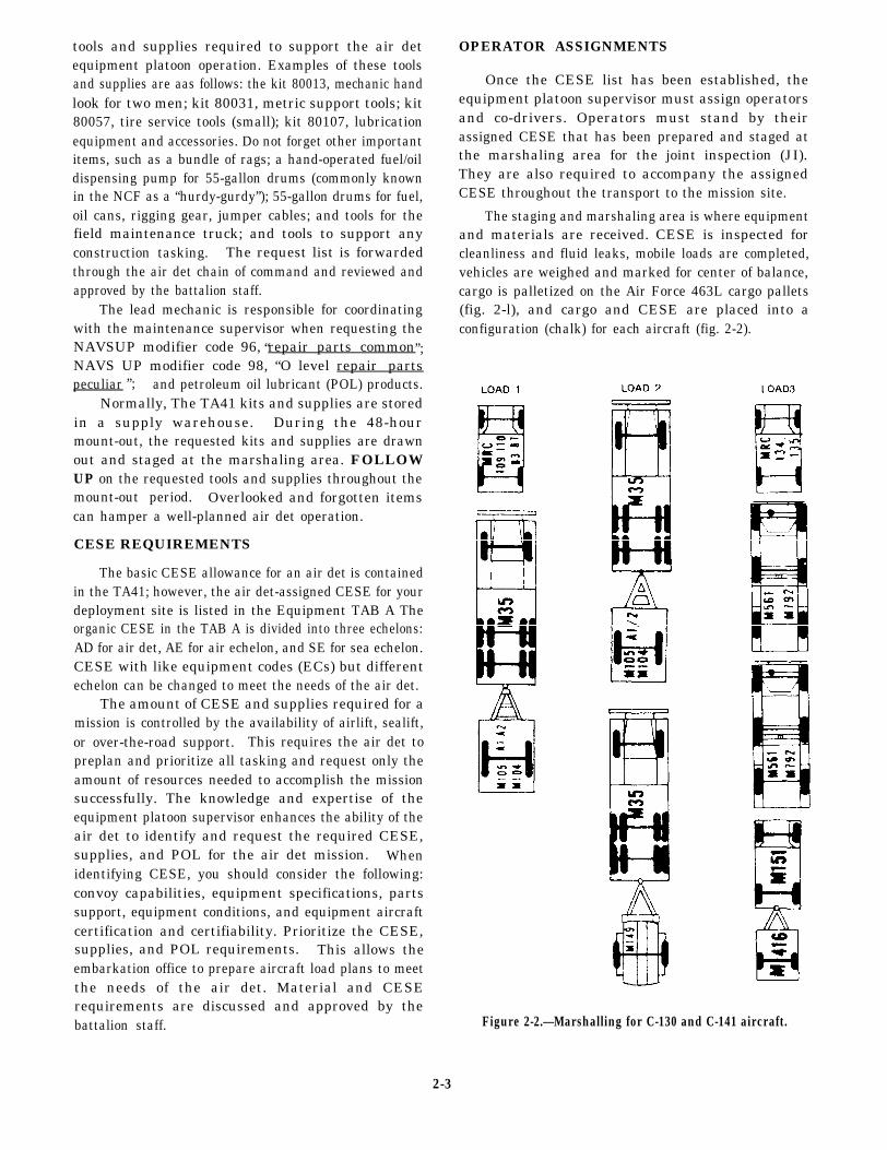
”;
tools and supplies required to support the air detequipment platoon operation. Examples of these toolsand supplies are aas follows: the kit 80013, mechanic handlook for two men; kit 80031, metric support tools; kit80057, tire service tools (small); kit 80107, lubricationequipment and accessories. Do not forget other importantitems, such as a bundle of rags; a hand-operated fuel/oildispensing pump for 55-gallon drums (commonly knownin the NCF as a “hurdy-gurdy”); 55-gallon drums for fuel,oil cans, rigging gear, jumper cables; and tools for thefield maintenance truck; and tools to support anyconstruction tasking. The request list is forwardedthrough the air det chain of command and reviewed andapproved by the battalion staff.
The lead mechanic is responsible for coordinatingwith the maintenance supervisor when requesting theNAVSUP modifier code 96, repair parts commonNAVS UP modifier code 98, “O level repair partspeculiar and petroleum oil lubricant (POL) products.
Normally, The TA41 kits and supplies are storedin a supply warehouse. During the 48-hourmount-out, the requested kits and supplies are drawnout and staged at the marshaling area. FOLLOWUP on the requested tools and supplies throughout themount-out period. Overlooked and forgotten itemscan hamper a well-planned air det operation.
CESE REQUIREMENTS
The basic CESE allowance for an air det is containedin the TA41; however, the air det-assigned CESE for yourdeployment site is listed in the Equipment TAB A Theorganic CESE in the TAB A is divided into three echelons:AD for air det, AE for air echelon, and SE for sea echelon.CESE with like equipment codes (ECs) but differentechelon can be changed to meet the needs of the air det.
The amount of CESE and supplies required for amission is controlled by the availability of airlift, sealift,or over-the-road support. This requires the air det topreplan and prioritize all tasking and request only theamount of resources needed to accomplish the missionsuccessfully. The knowledge and expertise of theequipment platoon supervisor enhances the ability of theair det to identify and request the required CESE,supplies, and POL for the air det mission. Whenidentifying CESE, you should consider the following:convoy capabilities, equipment specifications, partssupport, equipment conditions, and equipment aircraftcertification and certifiability. Prioritize the CESE,supplies, and POL requirements. This allows theembarkation office to prepare aircraft load plans to meetthe needs of the air det. Material and CESErequirements are discussed and approved by thebattalion staff.
OPERATOR ASSIGNMENTS
Once the CESE list has been established, theequipment platoon supervisor must assign operatorsand co-drivers. Operators must stand by theirassigned CESE that has been prepared and staged atthe marshaling area for the joint inspection (JI).They are also required to accompany the assignedCESE throughout the transport to the mission site.
The staging and marshaling area is where equipmentand materials are received. CESE is inspected forcleanliness and fluid leaks, mobile loads are completed,vehicles are weighed and marked for center of balance,cargo is palletized on the Air Force 463L cargo pallets(fig. 2-l), and cargo and CESE are placed into aconfiguration (chalk) for each aircraft (fig. 2-2).
“ ”;
Figure 2-2.—Marshalling for C-130 and C-141 aircraft.
2-3

During the home-port period, a pre-JI isconducted before the JI by the battalion embarkationofficer and the regiment embarkation staff from PortHueneme, California, or Gulfport, Mississippi. Whendeployed overseas, the pre-JI is performed byCOMSECOND/COMTHIRDNCB embarkationrepresentatives. The pre-JI includes the inspection ofall chalks of CESE, marriages and mobile loads ofCESE, hazardous materials, and Special HandlingData/Certification (DD Form 1387-2) (fig. 2-3), and463L pallet loads. The pre-JI allows the battaliontime to correct any discrepancies before the mainjoint inspection (JI).
NOTE: Ensure members are licensed forCESE assigned. licenses can be checked during thisinspection.
The JI is conducted by the battalionembarkation officer, regiment orCOMSECOND/COMTHIRD-NCB representatives,and the combat cargo officer of a ship or, foraircraft, the Departure Airfield Control Element(DACE) in conjunction with the U.S. Air ForceAirlift Control Element (ALCE). The jointinspection is recorded on the DD Form 2133 (fig.2-4).
Information concerning the operationsof the marshaling area or joint inspectionsare provided in the MAC AffiliationTraining Program Airlift Planners Course,MAC pamphlet 50-13, and the NavalConstruction Force Embarkation Manual,
COMSECOND/COMTHIRDNCBINST 3120.1series.
CESE AND MATERIAL PREPARATION
Upon notification of the air det to mount-out,the battalion re-organizes and sets up a mount-outcontrol center (MOCC). The MOCC is under thedirection of the battalion executive officer. TheMOCC controls, coordinates, and monitors themovement of all personnel, supplies, and equipmentto the marshaling area. The MOCC and theembarkation staff control all aspects of an NMCBmount-out and serve as the coordinating center for allthe companies and battalion staff.
During this period, the battalion is normallyorganized into 12-hour shifts. Alfa company isresponsible for all CESE preparation. The flow of theCESE through Alfa company is similar to the BEEPflow chart listed in chapter 1. During this timeperiod, the air det is usually involved in briefings,medical and dental checkups, administration officecheckups, and personnel readiness inspections.However, YOU need to schedule time to communicatewith Alfa company, and FOLLOW UP on the statusof CESE requested. Remember, the battalion ispreparing CESE and supplies for the air det that youwill have to live with.
Embarking on an aircraft requiresspecial loading procedures for several typesof CESE assigned to the battalion TOA.These procedures are outlined in the
Figure 2-3.—Special Handling Data/Certification, DD Form 1387-2.
2-4

Figure 2-4.—Joint Airlift Inspection Record, DD Form 2133.
2-5

Naval Construction Force Embarkation Manual,COMSECOND/COMTHIRDNCBINST 3120.1 series.Alfa company is responsible for following theseprocedures that include the following: the removal ofdump truck headache racks, equipment exhauststacks, dozer blades, counterweights, and equipmentroll over protective structure (ROPS). Also, the fueltank of a vehicle to be embarked by airlift must bebetween one-fourth and three-fourths full; however,when the vehicle has to be placed on the ramp insidethe aircraft, the fuel tank should never be more thanone-third full. Accomplishment of these procedures isa major area of responsibility for the air detequipment platoon; therefore, make sure you knowwhere Alfa company placed the bolts, nuts, and partsfor the disassembled equipment because the air detwill be required to reassemble these items on site.
After the CESE is cleaned, inspected, andserviced by Alfa company, the dispatcher notifies theMOCC that the CESE is ready to be transferred tothe Weighing and Marking station.
WEIGHING AND MARKING
To plan an airlift and to break down loads forindividual aircraft correctly, you must determine theweights and center of balance (C/B) of the two maindivisions: vehicles and general cargo.
The weight and center of balance of vehiclesare determined with secondary loads (mobile loads)mounted. Mobile loads are items of baggage or cargotransported in truck beds and trailers that must be
included in the total weight of a vehicle. To determinethe center of balance (C/B) on a vehicle, the 20thNaval Construction Regiment Embarkation Staff(R23), Gulfport, Mississippi, recommends thefollowing procedures:
Step 1. Establish the reference datum line(RDL). The RDL is the farthest forward point of avehicle.
Step 2. Measure distance 1 (D1). D1 is themeasurement in inches from the RDL to the centerline of the front axle.
Step 3. Measure distance 2 (D2). D2 is themeasurement in inches from the RDL to the centerline of the intermediate axle or rear axle.
NOTE: The distance 2 measurement locationfor vehicles with tandem axles is measured from theRDL to the trunnion.
Step 4. Measure distance 3 (D3). D3 is themeasurement in inches from the RDL to the centerline of the rear axle. This step is performed onvehicles that have three or more axles and ontowed vehicles that will remain married (attached)to a vehicle when loaded on the aircraft. The axleson a towed vehicle will become D4, D5, and soforth (fig. 2-5).
To perform Steps 5, 6, and 7, drive the vehicleonto portable scales (fig,. 2-6) placed under the tireson each axle.
Figure 2-5.—CESE distance measurement locations.
2-6

Figure 2-6.-Portable scales.
Step 5.(FAW). The
Determine the forward axle weightFAW is the total weight reading of the
scales under each front tire. Example: The left fronttire scale reads 3,000 pounds, and the right front tirescale reads 3,000 pounds, and the FAW equals 6,000pounds. This “FAW” is written (FAW 6,000) on apiece of weather-resistant material, such as duct tape,with a grease pencil,fender above the axle.
and attached to the vehicleRemember, this tape must be
removed upon arrival at the site to avoid the removalof the paint on the vehicle.
Step 6. Determine the intermediate axle weight(IAW). The IAW is the total weight reading of thescales under the intermediate tires. Follow theprocedures for Step 5 and label the reading as “IAW”on the masking tape. Remember, the IAW is theweight readings of both scales added together andrecorded in pounds.
Step 7. Determine the rear axle weight (RAW).The RAW is the total weight reading of the scalesunder the rear tires. Follow the procedures for Step 5and label the reading as “RAW’ on the masking tape.Remember, the RAW is the weight readings of bothscales added together and recorded in pounds.
NOTE: The RAW for vchiclcs with tandem axlesis the weight of the IAW and the RAW added togetherand labeled above the trunnion (fig. 2-7).
Step 8. Compute moment 1 (Ml). The formulafor M 1 is distance 1 times the forward axle weight orD1 x FAW = M1.
Step 9. Compute moment 2 (M2). The formulafor M2 is distance 2 times the intermediate axleweight or D2 x IAW = M2
Figure 2-7.—Marking procedures.
2-7

Figure 2-8.—Weight and balance of trackedvehicle.
Step 10. Compute moment 3 (M3). The formula forM3 is distance 3 times the rear axle weight or D3 XRAW = M3.
Step 11. Compute the gross vehicle weight(GVW). The formula for GVW is FAW + IAW + RAW= GVW.
Step 12. Determine the total moment (TM).TM is determined by adding all the momentstogether. The formula is Ml + M2 + M3 = TM.
Step 13. Compute the center of balance (C/B)of the vehicle. This is done by dividing the GVW intothe total moment, which provides the C/B value ininches.
Step 14. Locate the center of balance (C/B).The C/B is located by measuring from the RDL thenumber of inches computed in Step 13. At that point,label on the side of the vehicle with masking tape, aletter “T.” The horizontal portion of the tape islabeled “GVW” plus the weight. The vertical portionof the tape is labeled “C/B” and the distance in inchesmeasured from the RDL (fig. 2-7).
Although there are other procedures used tocompute the center of balance for vehicles, the aboveprocedures must be followed when you use thecomputer aided load manifest (CALM) computerprogram currently used in the NCF.
To find the C/B of a track vehicle (dozer),drive the vehicle onto a wooden beam until it balances(fig. 2-8). The weight of a track vehicle is determined
Figure 2-9.-Roller shoring.
2-8
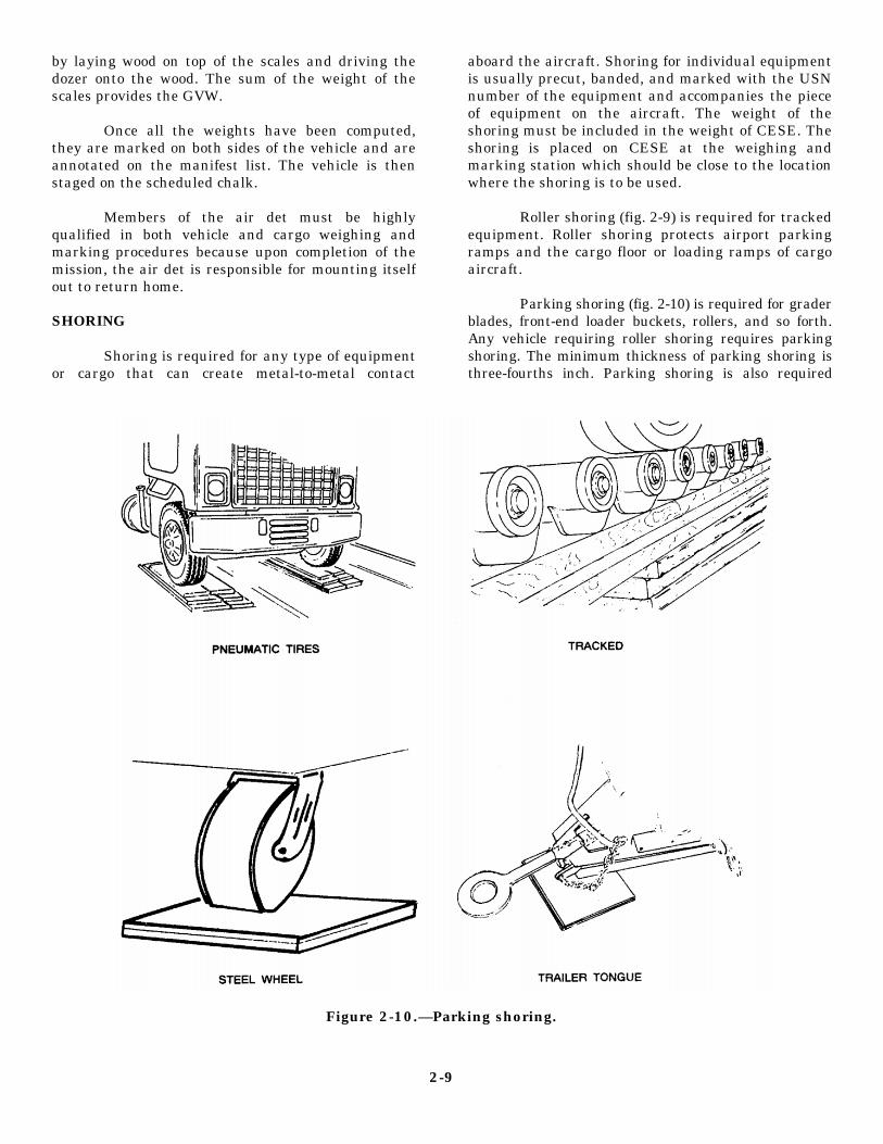
by laying wood on top of the scales and driving thedozer onto the wood. The sum of the weight of thescales provides the GVW.
Once all the weights have been computed,they are marked on both sides of the vehicle and areannotated on the manifest list. The vehicle is thenstaged on the scheduled chalk.
Members of the air det must be highlyqualified in both vehicle and cargo weighing andmarking procedures because upon completion of themission, the air det is responsible for mounting itselfout to return home.
SHORING
Shoring is required for any type of equipmentor cargo that can create metal-to-metal contact
aboard the aircraft. Shoring for individual equipmentis usually precut, banded, and marked with the USNnumber of the equipment and accompanies the pieceof equipment on the aircraft. The weight of theshoring must be included in the weight of CESE. Theshoring is placed on CESE at the weighing andmarking station which should be close to the locationwhere the shoring is to be used.
Roller shoring (fig. 2-9) is required for trackedequipment. Roller shoring protects airport parkingramps and the cargo floor or loading ramps of cargoaircraft.
Parking shoring (fig. 2-10) is required for graderblades, front-end loader buckets, rollers, and so forth.Any vehicle requiring roller shoring requires parkingshoring. The minimum thickness of parking shoring isthree-fourths inch. Parking shoring is also required
Figure 2-10.—Parking shoring.
2-9

Figure 2-11.-Sleeper shoring.
for all vehicles and cargo that exceed aircraft specificfloor weight limitations.
Sleeper shoring (fig. 2-1 1) is used under the frameor axle of a vehicle that exceeds 20,000 pounds and isequipped with soft tires. This shoring is used to preventthe vehicle from bouncing up and down and possiblypulling the tic-down rings out of the aircraft floor.
Approach shoring (fig. 2-12) is used to decrease theapproach angle of aircraft loading ramps, because someitems of cargo will strike the aircraft or ground duringloading or off-loading operations. Long vehicles, suchas low-boy trailers, that have limited ground clearancerequire a varying amount of approach shoring.
The air det must maintain custody of allshoring throughout the mission. Shoring shouldnot be used as tent flooring, tables, or as chairs.Shoring can be easily misplaced and should bestored off the ground in one location to preventinsect infestation, rot, or theft. The equipmentplatoon should account for all shoring assignedto each piece of CESE because this shoring willbe required for additional airlift plans. Shoringrequirements for air certified air det CESE islisted in the N a v a l C o n s t r u c t i o n F o r c eEmbarkation Manual, COMSECOND/COM-THIRDNCBINST 3120.1 series.
Figure 2-12.—Approach shoring.
2-10

PALLETIZED CARGO
Pallets and pallet nets are procured from the AirForce. The 463L pallet (fig. 2-1) is standard systemfor the movement of concentrated cargo used by theAir Force. Military airlift aircraft are equipped with adual-rail system consisting of rows of rollers whichallow 463L pallets to move easily into and out of theaircraft.The 463L pallet is made of corrosion-resistant aluminum and has a soft wood core. Thepallet has an outside dimension of 108 inches by 88inches and is 2 1/4 inches thick. The cargo area spaceis 104 inches by 84 inches which is enough space to
allow 2 inches around the 436L pallets to attachstraps, nets, or other restraint devices. A 436L palletweighs 290 pounds empty and has a maximum loadcapacity of 10,000 pounds; however, to prolong palletlife, a load placed on a pallet should not exceed 7,500pounds.
Pallet nets provide adequate restraint for 10,000pounds of cargo when properly attached to the 463Lpallet. There are three nets to a set: two side nets andone top net (fig. 2-13). The side nets are green incolor, and the top net is yellow. The side nets attach tothe rings of the pallet, and the top nets are attached byhooks to the side nets. These nets have multiple
Figure 2-13.—463L pallet nets.
2-11

adjustment points and may be tightened to fit snuglyon most any load. A complete set of 463L nets (threenets) weighs 65 pounds. Other cargo restraints arechains and chain tic-down devices. These are usedfor large items, such as Conex boxes, Seabee shelters,and refer units, and so forth. Five-thousand-poundtie-down straps (fig. 2-14) are used to secureequipment attachments and provide individual itemrestraints. Additionally, the tie-down straps providesupplemental restraint to the 463L pallet nets.
Cargo is palletized from the heaviest to thelightest. Large and heavy objects are distributedevenly from the center of the pallet outward toprevent the pallet from becoming heavy on one end(fig. 2-15). Additionally, this helps maintain thecenter of balance at or new the center. Lighter orsmaller items are positioned on top or along the sideof the heavier cargo, Containers marked “THIS SIDEUP” are placed upright, and cargo with special labelsare faced outward whenever possible. Pallets shouldbe constructed in a square or pyramid shape wheneverpossible (fig. 2-16). This makes the load stable, easyto handle, and easier to secure on the pallet. Each463L pallet requires dunnage under the pallet whennot on board the aircraft. The dunnage consists ofthree pieces of 4-inch by 4-inch by 90-inch timber andis placed in the center and close to the outside edgesof the pallet. This prevents the pallets from warpingand enhances forklift operations. Each aircraft hasrestrictions as to the dimensional size and shapeparticular to that specific aircraft. Aisleways must bebuilt on pallet position three or four in a C-130aircraft. Check the particular requirements of theaircraft for which the load is prepared.
Figure 2-15.— Pallet cargo placement.
Figure 2-14.—5,000-pound tie-down strap. Figure 2-16.—463L square and pyramid pallet cargoplacement.
2-12

Figure 2-17.—Bare tine extenders.
The marking of the center of balance is notnecessary on individual 463L pallets. When 463Lpallet loads are built correctly, the center of balancewill be at or near the center. The pallets are weighedby using portable scales. The weight of the dunnagemust be weighed with the pallet. The scaled weight ofthe pallet is recorded on the manifest and labeled oneach side (88-inch dimension) of the 463L pallet.
Handling and loading 463L pallets with aforklift requires the use of fork extensions (tine forkextenders in order to support the weight and size ofthe pallet fully. Technical publications that governloading procedures for aircraft require forklift tinesbe a minimum of 72 inches in length.
Tine extenders are designed in twoconfigurations: bare tine extenders (fig. 2-17) androllerized tine extenders (fig. 2-18). The rollerizedversion of tine extenders is best suited for therapid handling of 463L pallets, while the bare tineextenders are more useful in pallet building andthe placement of mobile loads on beds of vehicles.Either type of extender is acceptable and can belocally manufactured; however, extreme caremust be exercised when handling 463L pallets,because the tine tips can easily damage a palletsurface and render it unusable. To allow forunloading aircraft and handling pallets at thecampsite, you must ensure a set of tine forkextensions are embarked with the cargo
Figure 2-18.—Rollerized tine extenders.
2-13

and CESE. The 12K Lift King forklift currentlyassigned to the NCF TOA has a set of roller tine forkextensions assigned as an attachment.
Once the air det has arrived on site, the palletloads are usually broken down and a supply area is setup for material and tool distribution. Never leave thepallets, pallet nets, chains, chain tie-down devices,and even the 5,000-pound cargo straps laying around.When you do, there is a good chance they will berendered useless after being run over, walked on,buried, or otherwise damaged or destroyed. Therecommended procedure for storing pallets is to placedown three sets of 4-inch by 4-inch dunnage and stackthe pallets ten high. Then, place three more sets of4-inch by 4-inch dunnage and stack ten more pallets.Never stack pallets upside down. This could damagethe rings or the aluminum surface. Also, never stackpallets over 40 high. Store all the 4-inch by 4-inchdunnage, chains, chain tie-down devices, and cargostraps in one location, and protect pallet nets fromadverse climatic conditions. The netting materialsmay mildew and deteriorate, and the metal hooks canrust if not properly cared for. The air det mustmaintain custody of 463L pallets, pallet nets, 4-inchby 4-inch dunnage, chains, chain tie-down devicesand cargo straps throughout the mission. These itemsare extremely expensive to purchase and refurbishand could be required for future airlift plans.
COLLATERAL EQUIPAGE
The Alfa company collateral equipage custodiandelegates the responsibility and accountability of theair det CESE collateral equipage and attachments tothe equipment platoon supervisor. This area ofresponsibility is usually delegated to the assigned airdet collateral equipage custodian. The custodianneeds to acquire a list of the collateral equipage andattachments embarked with the air det CESE. Theresponsibilities of the air det collateral equipage andattachment operation are the same us the battalion andis outlined in Equipment Management, COM-SECOND/COMTHIRDNCBINST 11200.1 series andcovered in chapter 1 of this TRAMAN. Propermanagement of collateral equipage and attachmentsenhances YOUR equipment management program forthe air det. When this area is neglected, a high cost airdet collateral equipage and attachment turn-in canoccur and detract from any effective equipmentmanagement program you may have attempted toenforce.
SITE SELECTION
The equipment platoon supervisor works closelywith the air det staff when considering an area to setup the equipment platoon operations. The selectionof the site depends upon the mission, the terrain, andclimatic conditions. When possible, locate theequipment platoon operations close to the center ofactivity to allow the equipment to be usedeconomically and efficiently.
Drainage must not be overlooked. In some areasyou may already have natural drainage, while otherareas may require construction of extensive drainagesystems. You must remember that large-scalegrubbing operations often produce damagingenvironmental effects. Save as much vegetation aspossible to prevent soil erosion.
Allow adequate space to turn around tractor-trailers, to build an equipment loading ramp, to buildan equipment parking area, and an area for equipmentmaintenance operations. Consider areas to dispersethe equipment in a tactical environment to lessenpossible damage from rocket or mortar attacks.Equipment parked in a neat, close file or in rowspresent large targets. Additionally, make sureentrances and exits are laid out to allow for a smoothflow of traffic and wide enough to accommodate thelargest piece of construction equipment.
Other areas to consider are as follows: locationsfor collateral equipage and attachments, dispatch andmaintenance tents, POL storage, storage for vehicleshoring, storage for the 463L pallets, and the vehiclewash area.
SITE ARRIVAL
When the air det embarks by airlift, all membersof the air det are listed on the manifest and arescheduled to fly by chalk numbers. The number ofpassengers (PAXs) allotted on an aircraft depends onthe weight of the cargo or CESE loaded on theaircraft. The Equipment Operators (EOs) assigned toa specific CESE accompany that CESE aboard theaircraft.
Normally, EOS are assigned, with support fromother ratings, the duties of the Arrival Airlift ControlGroup (AACG). The AACG group is usuallyscheduled to fly out on the first chalk, and at themission site supports the Air Force with the unloadingand staging of cargo and CESE from the aircraft. The
2-14

AACG group normally remains at the air base until allthe scheduled chalks arrive at the mission site.
The equipment platoon transports cargo, baggage,CESE, and personnel from the air field to thedeployment site. This movement may require atactical convoy or a nontactical convoy procedure.Convoy procedures are outlined in the NavalConstruction Force Embarkation Manual, COM-SECOND/COMTHIRDNCBINST 3120.1 series, andEquipment Management, COMSECOND/COM-THIRDNCBINST 11200.1 series.
During the first few days of an air det mission,before the supplies and CESE arrive and the camp iscomplctcd, the troops endure abnormal livingconditions which can be detrimental to their morale.Once the supplies start to arrive, the set up of priorityareas should immediately begin. These areas are theshower tent for hot showers, the galley tent for hotmeals, and berthing tents to store gear and to sleep in.When provided properly, these facilities will make aPROFOUND difference in the morale and welfare ofthe troops.
The support platoon has the key responsibility forthe camp setup. Some of the platoon’s responsibilitiesare: camp electrical distribution, camp tent layout,galley facilities, shower facilities, laundry facilities(depending on the duration of the mission), medicalfacility, communications gear setup, latrines, and soforth. The construction of an air det camp is an “allhands” effort.
Delays can hamper plans for personnel, supplies,CESE, and construction operations and force the airdet to have to regroup and manage with the resourceson hand. Therefore, every operation the air det isinvolved in must be prioritized.
EQUIPMENT PLATOON OPERATIONS
The equipment platoon primary responsibility isto support the requirements of the support platoon;however, it also has its own areas of responsibility.One area of responsibility is the control and account-ability of CESE. When control and accountability ofCESE is delayed and not implemented at the start ofthe mission, problems are sure to develop. Someproblems you can expect are unexplainable damagesto CESE, lost keys, neglected operator maintenance,loss of collateral equipage, and even theft.
Dispatch operations must start at the verybeginning of the mission. All operators who areassigned to fly with a piece of CESE must report tothe dispatcher when the CESE arrives at the missionsite. The dispatcher should have an equipment statusboard that denotes the status of all CESE and have anarea to secure equipment keys. Dispatch operationsmay have to be performed out of a box before thedispatch tent is erected. The dispatcher must plan forthese situations. The best method for control andaccountability is to Class “C” assign all CESE.
The air det has to account for all hours andmileage put on CESE during a mission. Theequipment platoon supervisor is responsible forreviewing dispatch logs and trip tickets as outlined inEquipment Management, COMSECOND/COM-THIRDNCBINST 11200.1 series, for an Alfacompany operations supervisor.
The equipment platoon supervisor must stay ontop of all equipment-related operations of the air detDuring the first few days of a mission, the forklift isone of the most important pieces of CESE. Theforklift is required to reassemble CESE, break downpallets, move tent boxes, unload tractor-trailers, andso forth; therefore, to ensure the optimum usc of theforklift, these tasks must be prioritized.
You must remember that SAFETY ISPARAMOUNT and CESE must bc reassembledbefore use. Reassembling CESE is a time-consuming forklift operation that delays individualpriorities of other members of the air det.Therefore, it must be understood and enforced thattasks do not always have to be accomplished withthe support of equipment and that waiting for theavailability of the equipment is not worth the timewasted. Use troops to accomplish tasks that can bedone manually (manual labor). Examples are:breaking down pallets, digging latrines, movingtent boxes, unloading trucks, and so forth. Thesetasks must be accomplished with or without thesupport of equipment.
The equipment platoon also has the responsibilityto check and fill the water buffalos with potable water,maintain the water in the shower water bladders, andmake daily garbage runs. These areas must not beoverlooked during the planning phase. A piece ofCESE (water truck, dump truck) will have to bededicated to support this task. Water buffalosnormally embark empty unless it is determined thatpotable water is not immediately available.
2-15

Equipment repair operations and the use of POLproducts and 55-gallon fuel drums must be closelymonitored to avoid any contaminating spills.Lubricating oil, fuel, hydraulic fluids, transmissionfluids, and antifreeze contain hazardous chemicalproperties. When these items are mishandled andspilled, they can leak into the groundwater system orinto the human food chain. Mishandling the“hurdy-gurdy” while dispensing fuel in vehicles or infuel cans can cause excessive fuel spills that can bedisastrous to the environment. Fifty-five-gallon fueldrums and POL products should be stored at least 50feet away from any structure and located so vehicles andequipment can be easily topped off at the end of eachday. Depending on your mission, the POL products and55-gallon drums should be in a protected position (awayfrom likely avenues of attack) that provides protectionto the fuel storage area as well as to adjacent facilities.Fire extinguishers must be placed for easy accessibilityand “No Smoking” signs must be posted in the POLproducts and fuel storage area.
Embarked with limited resources, themaintenance field crew and field crew truck play amajor role throughout the air det mission. The fieldcrew truck is loaded with the necessary tools andconsumable supplies. These tools and suppliessupport the reassembling of CESE, setting up lightplants, setting up camp electrical supply (generators),repair of hand tools, and so forth. Additionally, themaintenance field crew is required at the airfieldduring aircraft flight unloading operations in case apiece of CESE can not start or breaks down while onboard the aircraft. Depending on the mission, themaintenance field crew truck can be used fordelivering fuel by loading and securing a 55-gallondrum of fuel in the back of the truck. This expiditesfuel runs for equipment on construction projects or forthe camp generators. The requirements formaintenance field crew support requires a radio forcommunications with the maintenance field crew andthe air det camp. A field crew must be equipped withthe proper communication capability to respond tomission requirements expeditiously.
The air det maintenance supervisor should directthe operations of the maintenance field crew and alsoknow the status of all CESE assigned to the air det.The maintenance supervisor has the responsibility toset up the maintenance shop and set up a preventivemaintenance schedule for CESE assigned. Allmaintenance peerformed that requires repair parts,lube oils, or exceeds one man-hour must bedocumented.
Depending on the duration of the mission, the airdet normally schedules means for logistic support andcommunications with the main body. Equipmentrepair parts not covered in the mod 96 or mod 98normally can be acquired through this logisticsupport. The air det maintenance and equipmentmanagement program should mirror that of the mainbody. The management guidelines are provided inEquipment Management, COMSECOND/COM-THIRDNCBINST 11200.1 series.
The success of the air det mission is primary, butshould not be attained at the cost of destroyed CESE.Operator’s maintenance is mandatory and must bestrongly enforced by the entire air det chain ofcommand. CESE damaged by operator negligence orlack of operator maintenance is unacceptable.Equipment failure can seriously jeopardize missionsuccess.
PROJECTS
The primary purpose of the construction platoonis to perform construction operations for the air detwith the support of the equipment and supportplatoons. Construction tasking covers a large rangeof tasks that include disaster recovery operations, wardamage repairs, rapid runway repairs, humanitarianrelief, and constructing advance base functionalcomponents. The tailoring of ratings assigned to theair det is dependent upon the extent and variety of theassigned tasking.
The amount of time allotted to plan constructionprojects depends on the urgency of the air det toembark to the mission site. Urgent situations cancause the air det to embark and manage constructionprojects with just the basic TA41 items. Theequipment platoon supervisor has to plan CESEsupport for the construction projects, and prioritiesshould be set up as soon as possible due to the limitedamount of CESE embarked with the air det.Remember, priorities are subject to change,depending on operational conditions.
AIR DET MOUNT-OUT/RETROGRADE
At the completion of the mission, the air detreceives orders from higher command to prepare tomount-out to relocate or to return to the main bodysite. The air det will have to mount-out itself toinclude the weighing and balancing of CESE,building pallets, developing load plans, anddeveloping convoy procedures, if required. The air
2-16
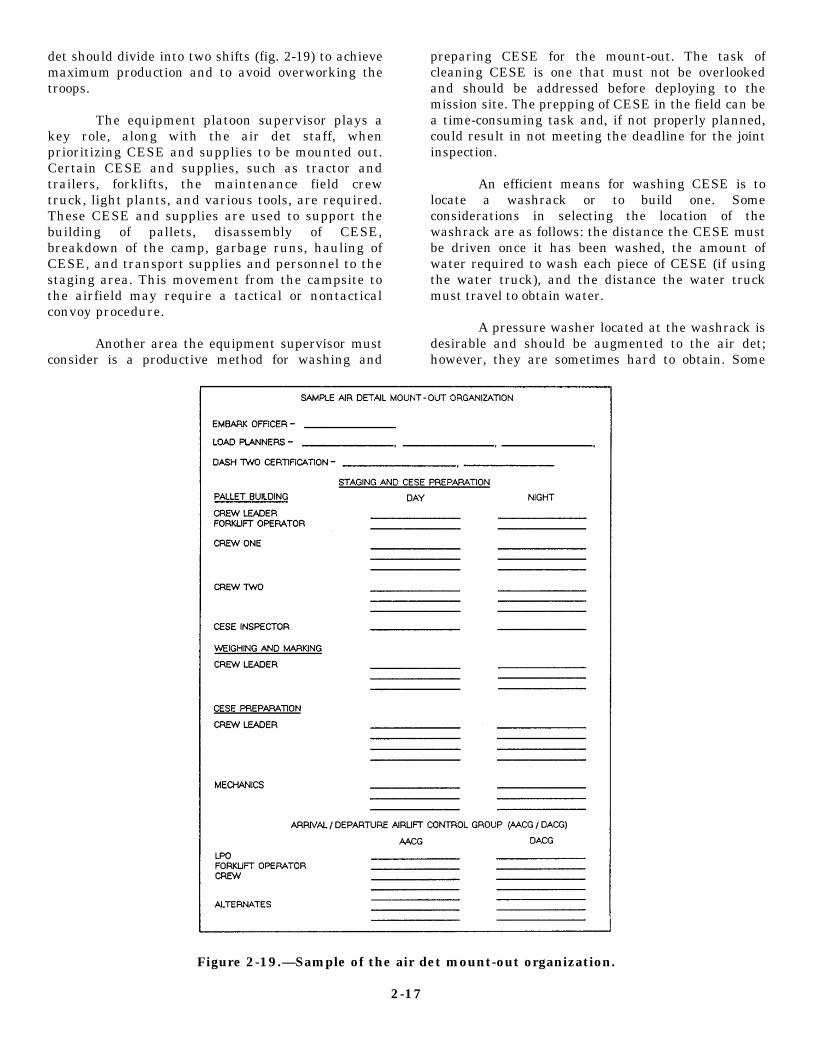
det should divide into two shifts (fig. 2-19) to achievemaximum production and to avoid overworking thetroops.
The equipment platoon supervisor plays akey role, along with the air det staff, whenprioritizing CESE and supplies to be mounted out.Certain CESE and supplies, such as tractor andtrailers, forklifts, the maintenance field crewtruck, light plants, and various tools, are required.These CESE and supplies are used to support thebuilding of pallets, disassembly of CESE,breakdown of the camp, garbage runs, hauling ofCESE, and transport supplies and personnel to thestaging area. This movement from the campsite tothe airfield may require a tactical or nontacticalconvoy procedure.
Another area the equipment supervisor mustconsider is a productive method for washing and
preparing CESE for the mount-out. The task ofcleaning CESE is one that must not be overlookedand should be addressed before deploying to themission site. The prepping of CESE in the field can bea time-consuming task and, if not properly planned,could result in not meeting the deadline for the jointinspection.
An efficient means for washing CESE is tolocate a washrack or to build one. Someconsiderations in selecting the location of thewashrack are as follows: the distance the CESE mustbe driven once it has been washed, the amount ofwater required to wash each piece of CESE (if usingthe water truck), and the distance the water truckmust travel to obtain water.
A pressure washer located at the washrack isdesirable and should be augmented to the air det;however, they are sometimes hard to obtain. Some
Figure 2-19.—Sample of the air det mount-out organization.
2-17
pressure washers require small quantities of water andcan be connected to a water buffalo with a gardenhose to provide a very efficient tool for washingCESE.
A de-bugging steam wash may be required on allCESE that is to be returned to the host country.Normally, this is a rule directed by the Department ofAgriculture of the host nation.
After all the pallets are built and the CESE isprepared, the air det has the responsibility to developits own load plans and to set up the marshaling areaby chalks. A pre-JI inspection is normally held thatallows the air det time to correct any discrepancy.Again, operators must stand by their CESE during theinspection.
The “fly away” can take several days; therefore,arrangements should be made for rations and berthingfor those personnel who are scheduled on the lastchalks. The maintenance field crew is normallyamong those personnel. The field crew is required tostand by to repair any unplanned breakdowns ofCESE that are to be loaded on (he aircraft. Anothergroup of personnel that remains at the airfield is theDeparture Airlift Control Group (DACG). TheDACG supports the Air Force with the loading andsecuring of CESE and 463L pallets onto the aircraft.
Normally, the majority of air det personnel aremanifested to be on the first group of chalks to fly out.These members will have the responsibility toperform the air det retrograde. The retrograde is theperiod of time used to inventory, reorder, clean, and
turn in all the supplies and gear embarked with the airdet.
Normally, CESE returning from the air detoperation is directed through the maintenance shop.This allows CESE to receive an acceptance checkbefore being returned to the field. The air detmaintenance supervisor turns in all the EROs, 1250s,and vehicle history jackets (if deployed more than 30days) used during the mission to the cost controlclerk. The license examiner turns in all licenserelated items and any accident reports to the battalionlicense examiner and the air det dispatcher turns in theclosed out dispatch logs, hard cards, and mileagereports to the battalion dispatcher. All collateralequipage is inventoried and turned over to thebattalion collateral equipage custodian.
After the completion of the retrograde, the air detchain of command will forward an after action reportto the battalion chain of command. This reportcontains a daily diary of events, the personnelembarked, CESE and supplies embarked, taskassigned and completed, man-days expended, andlessons learned, and so forth. Therefore, remember tokeep records of lessons learned throughout themission. This will support the after action report, plushelp plan future missions
Remember, the final condition of CESE, thepositive accountability of collateral equipage, and thepositive accountability of tool kits are your final gradeon how well the equipment management program wasconducted during the air det mission.
2-18

CHAPTER 3
CRANE CREW SUPERVISOR
In minutes, a crane can easily lift and place a loadweighing several tons. Major tasks involved in anyconstruction or ship-loading operation are thehandling of supplies, the driving of piles, and theexcavation of materials. Most of these tasks areperformed by equipment belonging to the lifting andloading family. Part of this family are cranes withvarious attachments, such as hook block, clamshell,dragline, and pile driver. Cranes provide safe andefficient accomplishment of assigned tasks whenoperators use them properly and demonstrate thesame respect for the crane as they should any otherlabor-saving device; however, the first time you bendthe rules or take shortcuts, disaster is waiting tohappen.
As a direct result of OPERATOR ERROR, craneaccidents take heavy and tragic tolls each year.People are crippled or killed and enormous propertydamage is incurred as a direct result of craneaccidents. Nine out of ten crane accidents thatoccurred in the past could have been avoided. Overeighty percent of these accidents were due to operatorinattention, poor judgment, overconfidence, orexcessive speed.
The Naval Construction Force (NCF) has formany years recognized the requirement for anextensive crane safety program. The crane safetyprogram applies to crane operators and the safeoperation of weight-handling equipment. Standardsfor weight-handling equipment operations areoutlined in the Management of Weight-HandlingEquipment, NAVFAC P-307; NCF EquipmentManagement Manual, NAVFAC P-404; NMCBEquipment Management, COMSECOND/COM-THIRDNCBINST 11200.1 series; Use of Wire RopeSlings and Rigging Hardware in the NCF,COMSECOND/COMTHIRDNCBINST 11200.11;and Testing and Licensing of Construction EquipmentOperators, NAVFAC P-306.
CRANE CREW SUPERVISORRESPONSIBILITIES
The Naval Construction Force crane crewsupervisor is assigned and designated in writing by
the commanding officer. The person selected isnormally the best crane operator available withinbattalion-wide assets. The equipment officer, cranetest director, and the crane crew supervisor share theresponsibility of ensuring that any crew that prepares,assembles, operates, or works with or around cranesare well trained in both safety and operatingprocedures.
CRANE CREW
The equipment officer and the Alfa companyoperations chief should select the crane crew at thebeginning of the home-port period. Constructiontasking requiring crane support and the number ofcranes assigned in the TAB A dictate the size of thecrane crew.
During the home-port period the crane crewsupervisor should be aware of and review allconstruction tasking that requires crane support. Aknowledge of crane operations enhances your abilityto make proper plans to meet construction tasking.Proper planning means you select the correct numberand types of crane lifts, assign the correct type ofcrane needed to accomplish the task, select the correctrigging gear, and assign a competent crew to performthe lift. Additionally, if any special skills are requiredto perform any of the tasking, you should know thatspecial training can be coordinated through yourbattalion training department with the NavalConstruction Training Center (NCTC), PortHueneme, California, or Gulfport, Mississippi.
Qualifications
The skills and safety standards demanded forefficient crane operations require only matureprofessionals be assigned as crane operators andriggers on a crane crew. Equipment Operators mustmeet the minimum physical examinationrequirements as established by the NAVFAC P-306.Additionally, they must pass a written and operationalskills test.
3-1

Crane License Program
Before receiving a license to operate a crane,crane operators are required to attend 40 hours offormal classroom instruction on crane operatingsafety, as outlined in the NAVFAC P-306. TheNaval Construction Training Centers (NCTC), PortHueneme, California, and Gulfport, Mississippi,offer a crane school that covers the requirements ofthe NAVFAC P-306. Additionally, operators whoneed to renew their license and have completed the40 hours of crane safety must attend a minimum8-hour refresher training course on crane operatorsafety.
The testing of crane operators is the directresponsibility of the crane certifying officer andcannot be delegated. The crane certifying officer maybe assisted in administering a performance test by thecrane test director. Performance tests are conducted,as outlined in the NAVFAC P-306. The cranemanufacturer’s manual is used to test the operator onthe operator’s maintenance responsibility.
The equipment officer is normally responsible forthe duties of the battalion crane certifying officer. Asoutlined in the NAVFAC P-307, the crane certifyingofficer must be designated in writing by thecommanding officer of the activity. The cranecertifying officer designates in writing the crane testdirector.
A crane license is issued on the ConstructionEquipment Operator License, NAVFAC 11260/2, andwill indicate the make, model, capacity, and theattachments the operator is qualified to operate.Operators requiring more on-the-job training withcranes can be issued a training license for a periof of30 days. The trainee must be under the supervision ofa qualified crane operator. The training license mustdenote the make, model, capacity, and the attachmenton which the operator is to be trained.
Before you deploy, ensure that the crane crew hasseveral licensed crane operators. Your licensedoperators will be needed to support the BattalionEquipment Evaluation Program (BEEP) of the cranes.The crane certifying officer designates in writing thecrane test operator and the crane test mechanic.These positions are required for the crane certificationprogram. The crane certifying officers may alsodesignate an alternate crane test director, testoperator, and test maintenance backups.
BEEP
Cranes are normally condition inspected, loadtested, and certified annually, as prescribed in theNAVFAC P-307; however, in the NCF, lestprocedures for cranes are performed during theBEEP as a joint battalion effort. Time managementis important when performing the BEEP of thecrane area of responsibility. You must rememberthat the weight testing of cranes is a time-consuming event and should be completed before(he end of the BEEP.
The BEEP Equipment and Attachment EvaluationInspection Guides for cranes are issued by thedispatchers. The inspections of the cranes areperformed jointly by the EOs assigned to the cranecrews. Once the EOs have completed the Equipmentand Attachment Evaluation Inspection and the paperwork is taken to the dispatcher, the crane mechanicswill jointly inspect the crane, using the inspectionguides. The crane mechanics also have theresponsibility of performing the Crane ConditionInspection which is documented on the CraneCondition Inspection Record (figs. 3-1A and 3-1B).This inspection, commonly known as the “before,during, and after inspection,” is part of the craneweight-testing procedure and can be performed at thesame time the mechanics are performing theequipment and attachment inspection. The crane testdirector is also responsible for inspecting andreviewing the items on the Crane ConditionInspection Record.
After the crane is released from the shop, thecrane crew supervisors have the responsibility toprepare the crane for the weight-testing procedure.Accomplishing the weight test for certification of thecrane is important, because the ERO for the cranecannot be closed out until the crane is certified.
The weight testing of cranes requires the use ofbig, heavy weights, a stable foundation, and an areaclear of obstructions. Some deployment sites have anarea in Alfa company with weights for the weighttesting of cranes; however, Public Works Centersoverseas normally has an area allocated for the weighttesting of cranes. They normally allow the battalionsto schedule time periods for use of this area.
When a crane has to be transported to theweight-testing-area, the crane crew supervisors mustreceive the planned travel route to determine if lowwires, low overpasses, narrow bridges, or unsafeobstacles exist. The absolute limit of approach for
3-2

Figure 3-1A.—Crane Condition Inspection Record (Front).
3-3

Figure 3-1B.—Crane Condition Inspection Record (Back).
3-4

power lines must be the following: 0 to 125,000 electrical power source. You must inspect the cranevolts, 10 feet; 125,000 to 250,000 volts, 15 feet; over test pad area, slings and rigging gear, and obtain travel250,000 volts, 25 feet. Anytime you are traveling permits if required. This review is documented on thewith a crane, stay a minimum of 4 feet from any Crane Lift Checklist (fig. 3-2) outlined in the
Figure 3-2.-Crane Lift Checklist.
3-5

Figure3-3.—Sample of the Crane Operator’s Daily Checklist.
3-6

COMSECOND/COMTHIRDNCBINST 11200.1series.
The Crane Lift Checklist must be filled out bythe crane crew supervisor or the crane test directorbefore the crane can proceed to any project or makeany crane lifts. After the Crane Lift Checklist iscompleted, make sure you brief the operators andriggers on specifics of the lift and travel conditions.
Crane Operator’s Daily Inspection
Before a crane is operated or transported, itmust be thoroughly inspected by the operator. Theoperator uses the Crane Operator’s Daily Checklist(ODCL) (fig. 3-3). The operator visually inspects andchecks each item prescribed on the checklist.
When the operator observes a deficiency of aload-bearing or load-controlling part or safety device(major deficiency) or an operating condition thatwould cause the slightest loss of control or otherwise
render the crane unsafe, the operator must securethe crane and notify the crane crew supervisor. Thecrane crew supervisor informs the chain of commandof any crane problems.
The NAVFAC Form 11260/4 is additionallyused with the ODCL when dispatching the crane.The ODCL is turned into the crane crew supervisorat the end of each day or shift for review and signing.As outlined in the NAVFAC P-307, the minimumrequirement for retaining the ODCLs is the ODCLsfor the previous month of operation and the ODCLs ofthe current month of operation.
Wire Rope Inspection
Part of the ODCL inspection is the thoroughinspection of all wire rope before using a crane. Allrunning ropes in continuous service must be visuallyinspected for crushing, kinks, corrosion or otherdamage, broken wires, and proper lubrication (fig. 3-4). Other areas to inspect are the following:
Figure 3-4.—Common wire rope defects.
3-7

wire rope sockets, swagec fittings, swivels,pendants, and securing hardware for wear. Winchecnd fittings need only bebc disconnected ordisassembled when experience or visibleindications deem it necessary. The exact time forreplacement of the rope cannot be given becausemany variables are involved; however, safetydepends upon the use of good judgment inevaluating wire rope. The following conditions arereasons for wire rope replacement:
Running ropes—Six or more broken wiresrandomly distributed, broken or torn wires in one lay,or three broken wires in one strand in one lay.Replace end connections when there are any brokenwires adjacent to the end connection.
Boom pendant ropes—More than two brokenwires in one lay in sections beyond the end connectionor one or more broken wires at an end connection.
Kinks or crushed sections—Severe kinks orcrushed rope in straight runs where the wire rope coreis forced through the outer strands.
Flatened sections—Flat sections where thediameter across the flat section is less than five sixthsof the original diameter.
Wire rope wear—Measure wire rope with wirerope calipers (fig. 3-5) to check for wear accurately.Replace wire rope that has wear of one third of theoriginal diameter of outside individual wires. Acrescent wrench can be used as an expedient means tomeasure wire rope.
Wire Rope End Connections
Wire rope end connections must be as specifiedby the manufacturer. If wedge sockets are used,they develop only 70 percent of the breakingstrength of the wire rope due to the crushing actionof the wedge. Exercise caution when wedgedsocket connections are used to make rated capacitylifts. Wedge sockets are particularly subject towear, faulty component fit, and damage fromfrequent change outs, and are highly vulnerable toinadvertent wedge release, and disassembly in atwo-blocking situation. Wire rope clips that clampboth the dead end and live rope must not be usedwith a wedge socket (fig. 3-6).
Figure 3-5.—Measuring wire rope.
Such connectors are hazardous because theyrestrain the wedge from seating properly in thesocket. Wedge sockets must be installed as specifiedin the following procedures:
1. Cut and remove any section of wire rope thatwas used in a socket and was subject to sharp bendingand crushing before resocketing.
Figure 3-6.—Wedge socket.
3-8

2. Install the wedge socket carefully to ensurethe wire rope carrying the load is in direct alignmentwith the eye of the socket clevis pin so the load pull isdirect.
3. Place the socket upright and bring the ropearound in a large, easy-to-handle hoop. Extend thedead end of the wire rope from the socket for adistance of a least one rope lay length. Insert thewedge in the socket, permitting the rope to adjustaround the wedge.
4. As a safety precaution, install a wire ropeclamp on the dead end of the wire rope that comesout of the wedge socket (fig. 3-7). Measure the
distance from the base of the wedge socket to theclamp. This measurement is used as a guide to checkif the wire rope is slipping in the wedge socket
5. Secure the socket to a support and carefullytake a strain on the live side of the rope to ensure theproper initial seating of the wedge. Increase the loadgradually until the wedge is fully seated. Avoidapplying sudden shock loads.
Hook Block Inspection
The hook block and the hook is part of theODCL inspection. The operator must inspect the hookblock for cleanliness, binding sheaves, damaged or worn
Figure 3-7.—Wedge socket clip method.
3-9
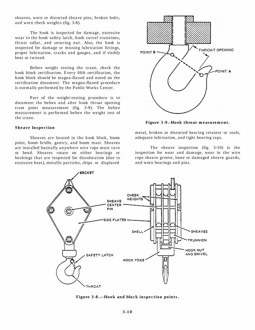
sheaves, worn or distorted sheave pins, broken bolts,and worn check weights (fig. 3-8).
The hook is inspected for damage, excessivewear to the hook safety latch, hook swivel trunnions,thrust collar, and securing nut. Also, the hook isinspected for damage or missing lubrication fittings,proper lubrication, cracks and gouges, and if visiblybent or twisted.
Before weight testing the crane, check thehook block certification. Every fifth certification, thehook block should be magna-fluxed and noted on thecertification document. The magna-fluxed procedureis normally performed by the Public Works Center.
Part of the weight-testing procedure is todocument the before and after hook throat openingtram point measurement (fig. 3-9). The beforemeasurement is performed before the weight test ofthe crane.
Sheave Inspection
Sheaves are located in the hook block, boompoint, boom bridle, gantry, and boom mast. Sheavesare installed basically anywhere wire rope must turnor bend. Sheaves rotate on either bearings orbushings that are inspected for discoloration (due toexcessive heat), metallic particles, chips or displaced
Figure 3-9.-Hook throat measurement.
metal, broken or distorted bearing retainer or seals,adequate lubrication, and tight bearing caps.
The sheave inspection (fig. 3-10) is theinspection for wear and damage, wear in the wirerope sheave groove, loose or damaged sheave guards,and worn bearings and pins.
Figure 3-8.—Hook and block inspection points.
3-10

Figure 3-10.—Sheave (Pulley) Inspection.
3-11

Figure 3-11.—Typical crane capacity chart.
3-12

TEST PROCEDURES
After the crane has been prestarted andtransported to the test pad, the crane crewsupervisors assist the crane test director to set up theweights for the weight-testing procedure. The cranecrew supervisors must know the length of boom andthe number of parts of line assembled on the crane.When testing cranes, you must test all the sections ofboom assigned to a crane during the crane testprocedures. The supervisors take the boom lengthmeasurement and the number of parts of line andreview the load charts (fig. 3-11) to determine themaximum-rated allowable load that the crane can lift.Mobile cranes are weight-tested at 110 percent of therated capacity. Crawler cranes are weight-tested at125 percent of the rated capacity. Complete tests areperformed on each hook, such as the main hoist andthe auxiliary or jib hoist. All rigging used in crane
load testing must have been previously tested to atleast 150 percent of the rated working load.
Test Weights
To determine the test weight for a mobilecrane, refer to the manufacturer’s load chartsassigned to the crane. To determine the test weightused in the following example, use the load chart infigure 3-11. When the crane is assembled with 60 feetof boom, the minimum radius noted on the load chartis 15 feet, with a rated capacity of 48,800 pounds. Donot rely on the boom angle indicator for radiusaccuracy when the lift exceeds 75 percent of the ratedcapacity; however, check the accuracy of the boomangle indicator by placing a 3-foot builder’s level onthe center boom section and raise or lower the boomuntil the level indicates the boom is level (fig. 3-12). Atthis point the boom angle indicator should show the
Figure 3-12.—Check accuracy of boom angle indicator.
3-13

boom is at zero degrees or adjusted to read zerodegrees. Measure the radius to avoid anypossibility of error. Take the 48,800 pounds andmultiply it by 110 percent (48,800 x 110% or 1.10 =53,680). The test weight for this crane example is53,680 pounds. After the test weight is figured,you must remember that the hook blocks andrigging gear are weight that are part of the testweight.
The number of parts of line rigged on the craneis important (fig. 3-13). Most load charts will havethe rated capacity of the crane for different partsof the line; for example, a crane that is capable ofbeing rigged with a eight-part line is rigged with asix-part line. Check the load chart for the six-partline capacity; take that rated capacity andmultiply it by 110 percent. The answer will beyour test weight.
Another weight to figure is the weight for thestability test. The stability test requires that themaximum test load be lifted first at the maximumradius and then be swung through eachmanufacturer’s recommended quadrant of
operation for the crane, which is normally over theside and rear. Using the load chart (fig. 3-11) withthe crane assembled with 60 feet of boom, themaximum radius is 55 feet. Note on the load charta rated capacity for over the rear and over theside. Since the weight has to be transferred fromone quadrant to the other as part of the testprocedure, use the recommended capacity for overthe side. You will find on some load charts therated capacity will be the same for over the sideand rear. The rated capacity for this example is8,400 pounds. Multiply the 8,400 by 110 percent(1.10). (8,400 X 1.10 = 9,240.) In this case, thestability test weight is 9,240 pounds. After the testweight is figured, you must remember that thehook blocks and rigging gear are weight that arepart of the test weight.
A third test weight to compute is the testweight for the auxiliary line, commonly knownas the whip line. This test weight is computedby the maximum load capacity for the winchhoist or the safe working load (SWL) of thewire rope installed on the winch. You mustremember that when the winch capacity is
Figure 3-13.—Eight-part line hook block.
3-14

greater than the SWL of the wire rope, the test weightwill be computed from the SWL of the wire rope or ifthe winch capacity is less than the SWL of the wirerope, the test weight will be computed from thecapacity of the winch. The winch capacity is eitherdocumented on the load charts or in themanufacturer’s manual.
The formula for computing the SWL for a hoistrope is the diameter of the rope squared multiplied by8 or (D x D x 8 = SWL in tons).
Example: The wire rope on a crane is 1/2 inch indiameter. Compute the SWL for the rope.
The first step is to convert the 1/2 into a decimalnumber by dividing the bottom number of the fractioninto the top number of the fraction: (1 divided by2 = .5). Next, compute the SWL formula: (.5 x .5 x 8= 2 tons). The SWL of the l/2-inch wire rope is2 tons.
The next factor to compute is the breakingstrength of the wire rope. On some wire rope spools,the nominal breaking strength of the wire rope ispublished; however, if the breaking strength isunknown, a break test can be performed on the wirerope. This is accomplished by cutting off sections ofthe wire rope and placing each section of the rope ona wire rope break test machine. The machine pulls thewire rope apart and computes the breaking strength.By testing several sections of the wire rope, you candetermine the average breaking strength for that typeof wire rope. Overseas, Public Works Centersnormally have wire rope break test machines that canbe used by the NCF. If the break test cannot beperformed, the rule of thumb used for finding thebreaking strength is to multiply the SWL by 5(SWL x 5 = B.S.). For example, a l/2-inch wire ropewith a SWL of 2 tons has a breaking strength of 10tons (2 x 5 = 10 tons). REMEMBER: When thesingle line wire rope end connection is assembledwith a wedge socket, the wedge socket only develops70 percent of the breaking strength. Example: Thecrane is rigged with l/2-inch wire rope with a wedgesocket end connection. The wedge socket onlydevelops seventy percent of the l/2-inch wire ropeB.S. of 10 tons, which gives the wire rope a B.S.determined by an end connection of 7 tons. Swagedsocket, cappel socket, and the zinc (spelter) socket allprovide 100 percent of the breaking strength whenproperly made.
The next factor to compute is the AWL by usingthe factor of safety (F.S.). To compute the allowable
working load (AWL) of a wire rope, you must firstunderstand the following wire rope safety factors:
1. Rigging rope
a. 5 to 1 under operating conditions
b. 10 to 1 when used to lift personnel
2. Pendants or standing rope
a. 3.0 to 1 under operating conditions
b. 2.5 to 1 when erecting the boom
3. Ropes that wind on drums or pass oversheaves
a. 3.5 to 1 under operating conditions
b. 3.0 to 1 when erecting the boom
For the auxiliary line, use the F.S. of 3.5 for wirerope that winds on drums or passes over sheaves. Theformula for the F.S. is the breaking strength (B.S.),determined by the type of end connection divided byF.S. (Example: B.S. = 7 divided by 3.5 = AWL of2 tons.)
The next factor to compute is the test weight.This is done by multiplying the AWL of 2 tons by 110percent (2 x 110% or 2 x 1.10 = 2.2 tons). Your testweight for the l/2-inch wire rope is 2.2 tons. After thetest weight is figured, you must remember that thehook blocks and rigging gear are weight that are partof the test weight.
Leveling a crane cannot be overemphasized.Cranes must be set up as per manufacturer’sinstruction, with the outriggers fully extended and thecrane leveled. Crane capacity is lost when the craneis out of level by a few degrees (fig. 3-14). Most
Figure 3-14.-Crane capacity lost by crane out of level.
3-15
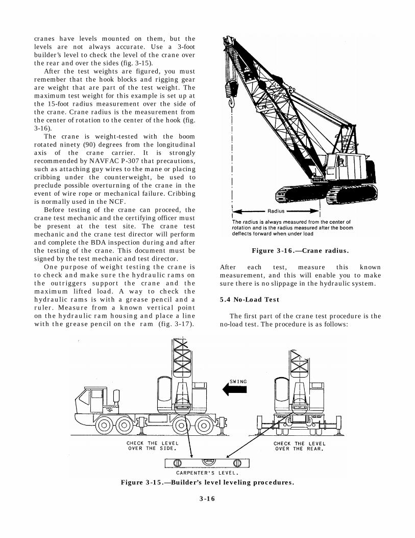
cranes have levels mounted on them, but thelevels are not always accurate. Use a 3-footbuilder’s level to check the level of the crane overthe rear and over the sides (fig. 3-15).
After the test weights are figured, you mustremember that the hook blocks and rigging gearare weight that are part of the test weight. Themaximum test weight for this example is set up atthe 15-foot radius measurement over the side ofthe crane. Crane radius is the measurement fromthe center of rotation to the center of the hook (fig.3-16).
The crane is weight-tested with the boomrotated ninety (90) degrees from the longitudinalaxis of the crane carrier. It is stronglyrecommended by NAVFAC P-307 that precautions,such as attaching guy wires to the mane or placingcribbing under the counterweight, be used topreclude possible overturning of the crane in theevent of wire rope or mechanical failure. Cribbingis normally used in the NCF.
Before testing of the crane can proceed, thecrane test mechanic and the certifying officer mustbe present at the test site. The crane testmechanic and the crane test director will performand complete the BDA inspection during and afterthe testing of the crane. This document must besigned by the test mechanic and test director.
One purpose of weight testing the crane isto check and make sure the hydraulic rams onthe outriggers support the crane and themaximum lifted load. A way to check thehydraulic rams is with a grease pencil and aruler. Measure from a known vertical pointon the hydraulic ram housing and place a linewith the grease pencil on the ram (fig. 3-17).
Figure 3-16.—Crane radius.
After each test, measure this knownmeasurement, and this will enable you to makesure there is no slippage in the hydraulic system.
5.4 No-Load Test
The first part of the crane test procedure is theno-load test. The procedure is as follows:
Figure 3-15.—Builder’s level leveling procedures.
3-16

5.4.1 Hoist. 5.5 Load Test
1. Raise and lower the hook through thefull-working distance of hook travel.
2. Run the hoist block into the limit switch orswitches, if installed, at slow speed.
3. Run the hoist block beyond the limit switch orswitches by using the bypass switch.
5.4.2 Boom.
1. Raise and lower the boom through thefull-working range.
2. Raise the boom into the upper limit switch(when installed). Raise the boom past the boomupper limit switch using the bypass switch.
3. Test the lower limit switch (when installed) bythe same proecdure prescribed for testing the upperlimit switch.
4. Extend and retract telescoping boom sectionstheir full distance of travel.
5. Check the radius indicator by measuring theradius at the minimum and maximum boom angle.
5.4.3 Motion.
Other motions, including swing, shall be operatedthrough one cycle (one-full revolution of majorcomponents).
The load test consists of basically two parts: amaximum load test and a stability test. The followingtest sequence is time and cost cffcctivc. The sequencemay be varied by the activity.
5.5.1 Maximum Test Load for the Crane on MainHoist.
1. Static Test. Raise the test load to clear theground with the boom at minimum radius and hold for10 minutes without boom and load hoist pawls (dog)engaged. Rotate the load and hook to check bearingoperation. Observe any lowering that may occur thatmay indicate a malfunction of the boom or hoistingcomponents, brakes, or outriggers. For hydrauliccranes, tests are performed with the boom fullyretracted and fully extended.
2. Dynamic Test. Raise and lower the test load atnormal operating speeds. Lower the test load to theground until the hoist lines are slack. Wait 5 minutes,hoist test load, and continue on with the test.
3. Hoist Brake. Test the ability of the brake tocontrol and stop the load (fig. 3-18). Test the abilityof the brake to hold and lower the test load with thefriction clutch disengaged, if applicable.
Figure 3-17.—Marking hydraulic rams.
3-17
Figure 3-18.-Hoist brake.

4. Boom Operation. Operate the boom fromminimum radius to maximum radius for the load applied.
5. Hydraulic Crane Slippage. Lift the test load atmaximum radius and allow time for fluid andcomponent temperatures to stabilize. Hold the loadfor 10 minutes without the operator using thecontrols. There should be no significant lowering ofthe load, boom, or outrigger beam due to a componentor system malfunction or failure during the test. Thesignificance of any lowering shall be evaluated by thecertifying officer, depending on operatingrequirements and safety.
5.5.2 Maximum Test Load at Maximum Radius ofCrane (Stability Test)
1. Boom Operation. Raise and lower the boomthrough the full-working range. Visually observe forsmooth operation. Test the boom brake for properoperation. For hydraulic cranes, the test is performedwith the boom fully retracted and fully extended.
2. Rotation. Rotate the crane left and right themaximum degrees allowed by the manufacturer atslow speed. Apply the brake periodically duringrotation. The brake should have the ability to stop therotating motion in a smooth, positive manner.
NOTE: Where brakes are designed for holdingonly, operate controls (plugging) to stop rotation thenapply brakes. Test shall be performed with boomfully retracted and fully extended.
3. Hydraulic Crane Slippage. Lift the test load atmaximum radius and allow time for fluid andcomponent temperatures to stabilize. Hold the loadfor 10 minutes without the operator using thecontrols. There should be no significant lowering ofthe load, boom, or outrigger beams due to acomponent or system malfunction or failure duringthe test. The significance of any lowering shall beevaluated by the certifying officer, depending onoperating requirements and safety.
5.5.3 Auxiliary and Jib Hoist.
The test load should be the maximum load for thehoist.
1. Static Test. Raise the test load to clear theground and hold for 10 minutes. Observe anylowering that occurs that may indicate a malfunctionof the hoisting components or brakes.
2. Dynamic Test. Raise and lower the test load atnormal operating speeds. Lower the test load to theground until the hoist lines are slack. Wait 5 minutes,hoist the test load, and continue the test.
3. Hoist Brake Test. Test the ability of the braketo control and stop the load. Next, test the ability ofthe brake to hold and lower the test load with thefriction clutch disengaged, if applicable.
5.5.4 Free-Rated Load Test.
To check the stability of the crane and operationof the crane carrier, wheels, tires, tracks, brakes, andso forth, under load. Retract outriggers beforebeginning the free-rated test.
CAUTION
ATTACH TAG LINES TO THE LOADTO CONTROL OSCILLATION.
NOTE: No static test is required (not applicableto mobile cranes temporarily mounted on barge).
1. Hoist the maximum free-rated test load at themaximum radius over the rear.
a. Rotate the load through the “over the rear”working arc.
b. Travel a minimum of 50 feet with the testload held over the rear of the crane with the boomparallel to the longitudinal axis of the crane carrier.
2. Hoist the maximum free-rated test load at themaximum radius over the side.
a. Rotate the load through the full-workingrange.
b. Travel a minimum of 50 feet with the testload over the left and then the right side of the cranecarrier with the boom 90 degrees to the axis of travel.
As outlined in the COMSECOND/COM-THIRDNCBINST 11200.1 series, rated free loads orpick and carry operations are only performedaccording to NAVFAC P-307 during a certification, incase of an emergency, or as directed by the cranecertifying officer.
5.5.5 Test After Change or Repair of Tires.
After change or repair of tires, the crane should betested with the maximum free-rated test load over theaffected tire(s). Raise and hold the test load for 10minutes while observing the changed or repairedtire(s).
5.6 Weight-Handling Equipment Used for Other ThanLift Crane Service.
Locomotive, crawler, truck, and cruiser cranesused for clamshell, dragline, magnet, pile driving, orother nonlift crane work should be tested at the
3-18

maximum safe working load permitted forthe size wire rope being used. This testshould be performed in all working motionsexcept travel. Buckets, magnets, and soforth, may be removed for testing wire rope.No test is required after reassembly.Retesting is not required when the endattachment is changed from the originalconnection (that is, changed from clamshelluse to dragline, and so on) during thecertification period.
Load Test Certification
After the test, the crane test mechanic andthe crane test director will jointly perform an afterinspection of the crane. This inspection isdocumented on the Crane Condition InspectionRecord.
Upon successful completion of the inspectionand load test, the certification of the load test andcondition inspection (fig. 3-19) must be prepared intriplicate. The following items are documented on thisform:
1. USN number of the crane
2. Type of crane
3. Rated capacity of the crane
4. Boom length of the crane
5. Location
6. Test date
7. Reason for test
Figure 3-19.—Certification of Load Test and Condition Inspection.
3-19

8.
9.
10.
11.
Hook tram point measurements (before andafter measurements)
Test weights lifted
Crane condition inspection record itemnumbers inspected
Test procedures paragraph numbersperformed, as outlined in NAVFAC P-307
The memorandum must be signed by the testdirector, the mechanical inspector, and the certifyingofficer. The original is filed in the appropriateequipment history jacket. One copy is filed in the unitsafety office, and the second copy is kept in anaccessible protected container on the crane. Thecertification date is stenciled with 3-inch stencils onthe operator’s side of the revolving house.
Frequency of Test
The command schedules each crane for periodiccondition and load tests. Test are conducted beforeplacing any crane into initial use. Cranes stored oridle for 6 months or more must be inspected andtested before returning to service. ANY MACHINET H A T H A S H A D M A J O R R E P A I R S O RREPLACEMENT OF LOAD BEARING ORCONTROLLING PARTS WILL ALSO BE TESTEDBEFORE IT IS PUT BACK IN SERVICE. Thedefinitions of load bearing and controlling are onlythose parts and components that support the load andwhose failure would result in uncontrolled dropping,shifting, or moving of the load. Tests may beconducted as frequently as local authorities deemadvisable (not to exceed 12 months between tests).
After the crane has passed the test procedures, themechanics will place the NMCB unit identificationmarking decal on the crane in the correct locations.
Extension of Certification
The commanding officer may approve in writinga temporary extension of the prior annual certificationwhen an emergent or other contingent conditionsexists precluding the timely certification of the crane.The authority to extend certifications cannot bedelegated. Before you extend the certification, thecrane must pass a complete condition inspection.
CRANE SAFETY
Loss in terms of lives, injuries, and equipment canbc dccrcascd with positive action and the use of safe
operating techniques by all Seabees working on oraround cranes.
Stability
Most crane mishaps result from operator error.Setting up for the lift is the most critical portion of thecrane operation. The most common causes ofmishaps are as follows:
1.
2.
3.
4.
Failure to block/crib under the outriggers padswhere poor ground conditions would notsupport the total weight of the crane and load.
Failure to extend the outriggers fully and use itfollowing the manufacturer’s instructions.
Failure to note overhead obstructions, such asoverpasses and power lines.
Failure to level the crane.
Load Capacity
The rated capacities of mobile cranes are based onboth strength and stability. Manufacturers of craneswill normally denote on the load charts a shaded areaor a bold line across the chart dividing the liftingcapacities based on strength or stability of the crane.It is extremely important to know the difference for, inone case, one of the structural components of thecrane will break, and in the other case, the crane willtip over. The following factors must also berecognized and the capacity adjusted accordingly:
1.
2.
3.
4.
5.
6.
7.
Do not use stability to determine liftingcapacity. Use the load chart installed by thecrane manufacturer. The load chart is securelyattached in the operator’s cab.
Recommended parts of hoist reeving and therecommended size and type of wire rope forvarious crane loads.
Length of boom.
Boom angle.
Boom pendant angle (when the telescopic/folding gantry is down, the angle decreasesand the stress increases).
Gantry and/or live mast in the highestposition.
Quadrant of operation (that is, over the side,over the rear capacities).
3-20

CAUTION
DO NOT RELY ON THE BOOMANGLE INDICATOR FOR RADIUSACCURACY WHEN LIFTS EXCEED 75PERCENT OF THE RATED CAPACITY.MEASURE TO AVOID THE POSSIBILITYOF ERROR.
NOTE: Capacity charts do not apply if themachine has been modified in any way. Ratedcapacity is based on the machine as it was originallymanufactured and equipped.
Safe Lifting
The following factors will give you some basicguidelines of what you must know to perform safedaily crane operations:
1.
2.
3.
4.
5.
6.
7.
8.
9.
1 0.
11.
12.
13.
Determine the weight to be lifted and thecrane required to make the lift safely.
Travel the proposed route the crane willfollow to and from the project site, andcomplete the Crane Lift Checklist.
Obtain the travel permits if required.
Brief operators and riggers on the specifics ofthe lift and travel conditions.
Inspect the crane area setup for stability andsafe operating area.
Fully extend the outriggers and use themaccording to the manufacturer’s instructions.
Check the machine for levelness.
Inspect slings, spreader bars, and all otherhardware being used.
Select the proper sling with sufficientcapacity rating.
Center the sling in the base (bowl) of thehook to avoid hook point loading, and ensurethat the hook block is always placed over thecenter of the load to eliminate shock loadingof the slings or cranes resulting from loadshifts when a lift is made.
Make ample safety allowances for unknownfactors.
Stand clear of and do not walk undersuspended loads.
Boom deflection.deflection. When
All crane booms havethe load is lifted off the
14.
15.
ground, the boom will deflect causing theradius to increase. Increased radius maycause overloading of the crane.
Clean operating area. Water coolers, excesstools, grease, soda cans, and other un-necessary items should be located outside theoperating area of the crane. Water coolersmust be kept off the crane to prevent peoplefrom walking around the crane when inoperation.
Weight on outriggers. On lattice booms,about 60 percent of the load is on theoutriggers close to the load. On hydrauliccranes during near capacity lifts at high boomangles, about 60 percent of the load is onoutriggers away from the load.
ATTENTION: SAFE LIFTING IS PARA-MOUNT! PROJECT COMPLETION MUST NOTINTERFERE WITH SAFE CRANE OPERATIONS!
Training
For deployed units, COMSECOND/COM-THIRDNCBINST 11200.1 series requires biweeklycrane operation and safety meetings be conducted.The meetings review crane operations and includegeneral safety, minimum rigging procedures, craneand rigging responsibilities, and upcoming lifts. TheAlfa company commander, crane test director, cranesupervisor and operators/riggers should attend themeetings.
Mishap Reporting
In addition to the requirements outlined inCOMSECOND/COMTHIRDNCBINST 5100.1series, any mishap involving NCF cranes must bereported by message to the COMTHIRDNCB DET,Port Hueneme, California, or the COMSECONDNCBDET, Gulfport, Mississippi.
WIRE ROPE SLINGS AND RIGGINGHARDWARE
The use of slings, hooks, spreader bars, shackles,and so forth, for lifting is a vital link in theweight-handling process. An in-depth managementprogram for the maintenance and use of slings isrequired to ensure the entire weight-handlingoperations are performed safely and professionally.The crane crew supervisors are responsible for the
3-21

inspection and turnover of all slings and rigging gearduring the BEEP.
Slings
Wire rope slings require special attention due tobeing subjected to severe wear, abrasion, impactloading, crushing, kinking, and overloading. Failureto provide blocking or protective pads permits sharpcorners to cut into the sling. Pulling slings fromunder loads results in abrasion and kinking. Droppingloads on slings or running equipment over slings willcause crushing. Sudden starts and stops when liftingloads will increase stress on the sling. The recom-mended factor of safety for wire rope slings is 5:1 dueto the severe service expended on slings, errors madein determining load weights, and the effects of slingstress from sling angles (fig. 3-20).
Single-Vertical Hitch
The single-vertical hitch (fig. 3-21) is a sling thatsupports a load by a single vertical part or leg of the
Figure 3-21.-Single-vertical hitch.
Figure 3-20.-Sling stress.
3-22

sling. The total weight of the load is carriedby a single leg with the sling angle of 90degrees.
Bridle Hitch
The bridle hitch can consist of two,three, or four single hitches (fig. 3-22), usedtogether to form a bridle hitch for hoisting anobject.
The bridle hitch provides excellent loadstability when the load is distributed equallyamong the legs, the load hook is directly overthe center of gravity of the load, and the loadis raised level. The use of a bridle slingrequires that the sling angles be carefullydetermined to ensure that the individual legsare not overloaded. It is wrong to concludethat a three- or four-leg bridle hitch willsafely lift a load equal to the safe load on oneleg multiplied by the number of legs, becausethere is no way of knowing that each leg iscarrying its share of the load. With a four-legged bridle sling lifting a rigid load, it ispossible for two of the legs to take practicallythe full load while the other two only balanceit. COMSECOND/COMTHIRDNCB stronglyrecommend that the rated capacities for two-leg bridle slings listed in the COMSECOND/COMTHIRDNCBINST 11200.11 series be usedalso as the safe load of three- or four-legbridle hitches.
Sling Angle
The rated capacity of any sling dependson the size, the configuration, and the anglesformed by the legs of the sling and thehorizontal. A sling with two legs used to lift a1,000 pound object will have 500 pounds of theload on each leg when the sling angle is 90degrees. The load stress on each leg increasesas the angle decreases; and if the sling anglewas 30 degrees lifting the same 1,000 poundobject, the load will be 1,000 pounds on eachleg. Try to keep all sling angles greater than45 degrees; sling angles approaching 30degrees are considered extremely hazardousand must be avoided at all cost.
Sling Safe Working Loads
It is a difficult task to remember all of the load,size, and sling combinations; however, the following
Figure 3-22.—Bridle hitch.
rules of thumb work well for estimating theloads in the most sling configurations.
The rules of thumb are based on thesafe working load of the single vertical hitchof a particular sling. The efficiencies of theend fittings used also have to be consideredwhen determining the capacity of thecombination.
3-23

The formula used to compute the safeworking load (SWL) for a bridle hitch with two, three,or four legs (fig. 3-23) is SWL (of single vertical hitch)x H (Height) divided by L (Length) x 2 = SWL. Whenthe sling legs are not of equal length, use the smallestH/L measurement. This formula is for a two-legbridle hitch but it is strongly recommended it also beused for the three- and four-leg hitches.
However, do not forget it is wrong to assumethat a three- or four-leg hitch will safely lift a loadequal to the safe load on one leg multiplied by thenumber of legs.
Other formulas are as follows:
Single-Basket Hitch (fig. 3-24): For verticallegs, SWL = SWL (of single-vertical hitch) x 2.
For inclined legs, SWL = SWL (of single-vertical hitch) x H divided by L x 4.
Double-Basket Hitch (fig. 3-25): For verticallegs, SWL = SWL (of single-vertical hitch) x 4.
For inclined legs, SWL = SWL (of single-vertical hitch) x H divided by L x 4.
Figure 3-23.—Determination of bridle hitch sling capacity.
3-24

Figure 3-24.—Determination of single-baskethitch sling capacity.
Single-Choker Hitch (fig. 3-26): For slingangles of 45 degrees or more, SWL = SWL (ofsingle-vertical hitch) x 3/4 or .75.
Figure 3-26.—Determination of single-chokerhitch sling capacity.
Sling angles of less than 45 degrees are notrecommended; however, if they are used, the formulais SWL = SWL (of single-vertical hitch) x A/B.
Figure 3-25.—Determination of double-basket hitch sling capacity.
3-25
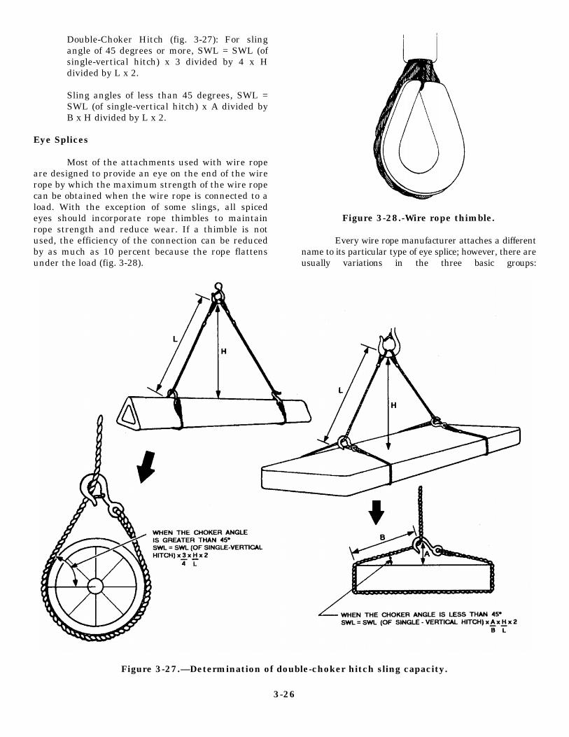
Double-Choker Hitch (fig. 3-27): For slingangle of 45 degrees or more, SWL = SWL (ofsingle-vertical hitch) x 3 divided by 4 x Hdivided by L x 2.
Sling angles of less than 45 degrees, SWL =SWL (of single-vertical hitch) x A divided byB x H divided by L x 2.
Eye Splices
Most of the attachments used with wire ropeare designed to provide an eye on the end of the wirerope by which the maximum strength of the wire ropecan be obtained when the wire rope is connected to aload. With the exception of some slings, all spicedeyes should incorporate rope thimbles to maintainrope strength and reduce wear. If a thimble is notused, the efficiency of the connection can be reducedby as much as 10 percent because the rope flattensunder the load (fig. 3-28).
Figure 3-28.-Wire rope thimble.
Every wire rope manufacturer attaches a differentname to its particular type of eye splice; however, there areusually variations in the three basic groups:
Figure 3-27.—Determination of double-choker hitch sling capacity.
3-26

Group 1:
Group 2:
Group 3:
Figure 3-29.-Flemish eye and serving.
Flemish eye and serving (fig. 3-29)Flemish eye and pressed metal sleeve(fig. 3-30)
Tucked eye and serving (fig. 3-31)Tucked eye and pressed metal sleeve(fig. 3-32)
Fold back eye and pressed metal sleeve(fig. 3-33)
Figure 3-30.-Flemish eye and pressed metal sleeve.
Figure 3-31.-Tucked eye and serving.
The splices in group one are the best andmost secure. The flemish eye with the pressedmetal sleeve is recommended for all rigging andhoisting use. When properly fabricated, itdevelops almost 100 percent of the cataloguebreaking strength. The strand ends of the splicedrope are secured against the live portion of therope by means of a steel or aluminum sleeve setin place under pressure.
Figure 3-32.—Tucked eye and pressed metal sleeve.
3-27

Figure 3-33.—Fold back eye and pressed metal sleeve.
The tucked eye with the pressed metal sleeve isalmost 100 percent efficient; however, the tucked eyeand serving in group 2 can develop only 70 percent ofthe strength of the rope and tend to come free as therope unwinds. As the rope untwists, the tucks in theeye begin to pop free. All eye spices in group 2should have a least five tucks, and the complete spliceshould be carefully and tightly wrapped with a wireserving to cover the whole splice.
The fold back eyes and pressed metal sleeves ingroup 3 are fabricated by bending the rope to the eyedimension required and securing the free or dead endof the rope against the live portion of the rope bymeans of a steel or aluminum sleeve set in place underpressure. Improper swaging or split sleeves used withfold back eye splices (fig. 3-34) can result in completefailure without warning. It is highly recommendedthat these eye splices never be used for overheadhoisting operations.
An alternate method of forming a soft eye in theend of a wire rope without the use of permanentsplicing is fabricating a flemish eye splice (MolleyHogan). The eye is simple to form, requiring aminimum amount of tools, and does not require use ofa splicing vise. The flemish eye develops 90 percentof the breaking strength of the wire rope.
To form a flemish eye (fig. 3-35), unlay the ropestrands 3 to 4 inches longer than twice the
circumference of the eye size desired. The wire ropecore can be cut out or laid in one section of the wire.A simple overhand knot is made, letting the strandslay together and adjusting the eye to the desired size.Bend sections of the strands through the eye so thatthe strands re-lay into position to form the rope.Continue until the eye is completed. Secure the bitterends of the strand to the rope with lashing, seizing, ora wire clip to prevent unlaying of the rope. Before thesling can be put into use, it must be proof-tested andtagged.
Proof-Testing
All field-fabricated slings terminated bymechanical splices, sockets, and pressed and swaged
Figure 3-34.-Fold back sling failure.
3-28

Figure 3-35.-Flemish eye development.
3-29

terminals must be proof-loaded before placing thesling in initial service.
The COMSECOND/COMTHIRDNCBINST11200.11 series has rated capacity charts enclosed fornumerous wire rope classifications. You must knowthe diameter, rope construction, type of core, grade,and splice on the wire rope sling before referring tothe charts. The charts will give you the vertical-ratedcapacity for the sling. The test weight for single-legbridle slings and endless slings is the vertical-ratedcapacity (V.R.C.) multiplied by two or (V.R.C. x 2 =sling test weight).
The test load for multiple-leg bridle slings mustbe applied to the individual legs and must be twotimes the vertical-rated capacity of a single-leg slingof the same size, grade, and wire rope construction.When slings and rigging are broken out of the TOAfor field use, they must be proof-tested and taggedbefore being returned to CTR for storage.
Records
The crane crew supervisor must establish andmaintain a card file system containing a record ofeach sling in the unit’s inventory. Proo fTest/Inspection Sheets (fig. 3-36) are used todocument tests made on all items of weight-liftingslings, spreader bars, hooks, shackles, and so forth.These records are permanent and contain thefollowing entries at a minimum:
1.
2.
3.
4.
5.
6.
7.
8.
Sling identification number (unit location andtwo-digit number with Alfa designation foreach wire rope component)
Sling length
Cable body diameter (inches) and specifi-cations
Type of splice
Rated capacity
Proof test weight
Date of proof test
Signature of proof test director
All the slings must have a permanently affixed,near the sling eye, durable identification tagcontaining the following information:
1. Rated capacity (in tons) (vert. SWL)
2. Rated capacity (in tons) (45-degree SWL)
3. Identification number
Spreader bars, shackles, and hooks must have therated capacities and SWL permanently stenciled orstamped on them. OSHA identification tags can beacquired at no cost from COMTHIRDNCB DET, PortHueneme, California, or COMSECONDNCB DET,Gulfport, Mississippi. Metal dog tags are authorizedproviding the required information is stamped ontothe tags.
Storage
Wire rope slings and associated hardware must bestored either in coils or on reels, hung in the riggingloft, or laid on racks indoors to protect them fromcorrosive weather and other types of damage, such askinking or being backed over. Slings are not to be lefton the crane at the end of the workday.
Sling and Rigging Gear Kits
The NCF has slings and rigging gear in theBattalion Table of Allowance to support the riggingoperations and the lifting of CESE. The kits 80104,84003, and 84004 must remain in the custody of thesupply officer in the central toolroom (CTR). Thedesignated embarkation staff and the crane testdirector monitor the condition of the rigging gear.During the BEEP, the two crane crew supervisorsnormally have the responsibility to inventory thecontents of the kits. The rigging kits must be storedundercover.
Wire Rope Sling Inspection
All wire rope slings must be visually inspected forobvious unsafe conditions before each use. Adetermination to remove slings from service requiresexperience and good judgment, especially whenevaluating the remaining strength in a sling afterallowing for normal wear. The safety of the slingdepends primarily upon the remaining strength. Wirerope slings must be immediately removed fromservice if any of the following conditions are present:
1. Six randomly distributed broken wires in onerope lay or three broken wires in one strand inone lay
2. Wear or scraping on one third of the originaldiameter of outside individual wires
3-30

Figure 3-36.-Proof Test/Inspection Sheet.
3-31

3.
4.
5.
6.
7.
Kinking, crushing, bird caging, or any otherdamage resulting in distortion of the wire ropestructure
Evidences of heat damage
End attachments that are cracked, deformed orworn
Hooks that have an obviously abnormal(usually 15 percent from the originalspecification) throat opening, measured at thenarrowest point or twisted more than 10degrees from the plane of the unbent hook
Corrosion of the wire rope sling or endattachments
To avoid confusion and to eliminate doubt, youmust not downgrade slings to a lower rated capacity.A sling must be removed from service if it cannotsafely lift the load capacity in which it is rated. Slingsand hooks removed from service must be destroyedby cutting before disposal. This ensures inadvertentuse by another unit. When a leg on a multiple-legbridle sling is unsafe, you only have to destroy thedamanged or unsafe leg(s). Units that have thecapability may fabricate replacement legs in the field,provided the wire rope replacement is in compliancewith specifications. The NCF has a hydraulicswaging and splicing kit in the Battalion Table ofAllowance. The kit, 80092, contains the tools andequipment necessary to fabricate 3/8- through5/8-inch sizes of wire rope slings. Before use, allfabricatedd slings must be proof-tested, as outlined inthe COMSECOND/COMTHIRDNCBINST 11200.11series.
Spreader bars, shackles, hooks, and so forth, mustalso be visually inspected before each use for obviousdamage or deformation.
A visual inspection of all active slings andrigging geat must be conducted by the crane crewsupervisor every 60 days. The inspections are notedon the Proof Testing/Inspection Record Cards. Anydeterioration that could result in an appreciable loss ofthe orginal strength of a sling or component justifiesit being removed immediately from service. Afterpassing inspection, a proof test must be conductedbefore returning a sling to service.
Wire Rope Maintenance
Wire rope must be thoroughly claened at regularintervals. A wire brush can be used to remove most ofthe dirt and grit that may accumulate on the wire.
Rust should also be removed when the rope iscleaned. After cleaning, you should allow the wirerope to dry before it is lubricated.
The object of cleaning wire rope is to remove allforeign material and old lubricant from the valleysbetween the strands and the spaces and between theouter wires to permit the lubricant to penetrate intothe rope.
Wire Rope Lubrication
Periodic lubrication of wire rope is essential toprolong the life of a rope. Lubricants generally do notlast through the life of a rope; therefore, this requiresthat the lubricant be renewed. A good grade of newoil or grease (never use engine oil) can be used for thispurpose. It should be free of acids and alkalis andshould be light enough to penetrate between the wiresand strands of the rope and applied as uniformly aspossible throughout the length of the rope.COMSECOND/COMTHIRDNCBINST recommendsthe use of 70:30 ratio of new oil to diesel fuel for awire rope lubricant. Wire rope should be cleaned andlubricated before storing.
Wire Rope Safe Operating Procedures
All personnel involved with the use of wire ropeslings should be thoroughly instructed and trained 10comply with the following practices:
1. Wire rope slings must not be used with loadsthat exceed the rated capacities outlined in enclosure(2) of the COMSECOND/COMTHIRDNCBINST11200.11 series. Slings not included in the enclosuremust be used only according to the manufacturer’srecommendation.
2. Determine the weight of a load beforeattempting any lift.
3. Select a sling with sufficient capacity rating.
4. Examine all hardware, equipment, tackle,and slings before using them and destroy all defectivecomponents.
5. Use the proper hitch.
6. Guide loads with a tag line when practical.
7. When using multiple-leg slings, selectlongest sling practical to reduce the stress onindividual sling legs.
8. Attach the sling securely to the load.
thethe
3-32

9. Pad or protect any sharp corners or edges thesling may come in contact with to prevent chaffing.
10. Slings are to be kept free of kinks, loops, ortwists.
11. Keep hands and fingers from between thesling and the load.
12. Start the lift slowly to avoid shock loadingslings.
13. Keep slings well lubricated to preventcorrosion.
14. Do not pull slings from under a load when theload is resting on the slings; block the load up toremove slings.
15. Do not shorten a sling by knotting or usingwire rope clips.
16. Do not inspect wire rope slings by passingbare hands over the rope. Broken wires, if present,may cause serious injuries. When practical, leatherpalm gloves should be worn when working with wirerope slings.
3-33


CHAPTER 4
PROJECT SUPERVISOR
The mission of the Naval Mobile ConstructionBattalion (NMCB) includes operational readiness,construction, defense, and disaster preparednessoperations. To achieve these assigned missions, theNMCB is organizationally structured for the dualpurpose of construction and military supportoperations.
The commanding officer (CO) of the NMCBhas direct responsibility for the timely preparednessand successful completion of all construction projectsand disaster recovery operations assigned to theNMCB by higher authority. The operations officer (S-3) is responsible to the CO for management of theconstruction and disaster preparedness programs.Additionally, the operations officer is granted directsupervisory authority over the utilization of thebattalion’s construction resources: personnel,equipment, and materials. The element in the overallNMCB organization by which the battalion’s missionis accomplished is the company structure (fig. 4-1).
The NMCB is composed of two categories ofcompanies: construction companies and line
Figure 4-1.—Model of an NMCB organization.
companies. Construction companies are designated asAlfa, Bravo, Charlie, and Delta. These companieshave the capabilities needed for direct missionaccomplishment. Headquarters company is the linecompany and serves as the military andadministration organization for the NMCB.
Within the battalion, Alfa company has theprimary responsibility for the operation andmaintenance of all assigned automotive, construction,and weight-handling equipment. Under theconstruction concept of prime contractor/leadcompany, Alfa company performs as a prime orsubcontractor, sometimes both, for assignedconstruction projects. The prime contractor isresponsible for the safety, quality, and timeliness ofthe construction effort and directs subcontractsupport accordingly. The subcontractor is responsiblefor providing resources in sufficient quantity andquality to accomplish a portion of a constructionproject according to schedules.
The Alfa company commander (A-6) isdirectly responsible to the operations officer (S-3) forAlfa company assigned projects. The Alfa companyoperation chief (A-3) is responsible to the companycommander for all prime and subproject support andnormally assigns a projects chief (A-32) to support themanagement of the construction projects. Thecompany commander, company operation chief, andprojects chief, and usually, the company chief jointlyreview the preliminary construction tasking for anassigned prime project or projects. They then selectthe project supervisor(s) who is/are given theresponsibility to carry out the project tasking. Thecompany selected project supervisor is appointed bythe operations officer for the assigned constructionproject.
PROJECT SUPERVISORRESPONSIBILITIES
In some commands, the project supervisor isreferred to as the “crew leader.” In this chapter, theterm project supervisor refers to the individualassigned as the person in charge of a constructionproject. This chapter presents the basic informationyou are required to know in order to perform theduties and carry out your responsibilities whenassigned as a project supervisor.
4-1

Figure 4-2.-Prime contractor/lead company organization.
Figure 4-3.-Project manager/resource manager organization.
CONCEPTS OF CONSTRUCTION concepts that are most often used by the NavalConstruction Force (NCF). These concepts are as
Construction operations are conducted under follows:several different organizational concepts. Dependingupon the particular objectives of each deployment, the l
CO and the S-3 officer determine the organizational lconcept that is most effective for the execution of theassigned objectives while maintaining readiness
l
Prime contractor/lead company
Project manager/resource manager
Self-sufficient unit/detail
integrity. Although there are many variations that can be Most construction operations in the NCF are
used in a construction organization, there are three conducted under the prime contractor/lead company
4-2

concept (fig. 4-2). In this organization the companycommanders are directly responsible to theoperations officer for the timely and successfulcompletion of construction projects assigned to themby the operations officer. The projectmanager/resource manager concept (fig. 4-3) requiresconstruction projects be assigned directly to a projectmanager who is normally outside the companyorganization. The project managers are thenresponsible directly to the operations officer for thecompletion of the project to include the following:planning, scheduling of resources, direct projectsupervision, and reporting. The entire battalion laborforce is reorganized into resource “pods,” either byrate or by type of work to be accomplished (such asblock crews, concrete crews, finish crews, and wiringcrews). A resource manager is placed in charge ofeach pool. The resource manager has theresponsibility to utilize their assigned personnel,tools, and equipment effectively, without regard toproject assignment, and provide the administrationsupport required by the military organization. Theself-sufficient unit concept (fig. 4-4) is used when thebattalion establishes details to accomplish specifictasks at locations remote from the main body site.These details are organized and staffed with allresources required to accomplish the specific assignedmission; therefore, the self-sufficient unit. The threeconcepts are outlined in the Naval Construction ForceManual, NAVFAC P-315.
No matter what construction concept is used,the prime contractor, project manager, or the officerin charge (OIC) of the self-sufficient unit is directlyresponsible to the operations officer.
DEPLOYMENT PLANNING
The key to a successful deployment is well-developedplans. This planning phase begins 2 months beforethe end of the previous deployment and continuesthrough the end of home port. More details of howconstruction projects are planned and laid out arecovered in the Naval Construction Force/SeabeePetty Officer First Class, NAVEDTRA 10601, and theNaval Construction Force/Seabee Chief Petty Officer,NAVEDTRA 10600. The following is a generaloverview of how deployment tasking is planned. Theplanning phase is subdivided into seven distinctsteps: initial planning step, follow-on planning step,detailed planning step, predeployment trip step,ready-to-deploy evaluation step, advance party phase(final evaluation step), and the main body arrivalstep.
The initial planning step is the period in whichthe battalion receives its preliminary tasking and begins
Figure 4-4.-Self-sufficient unit organization.
monitoring the efforts, plans, tasking, and work loadof the on-site battalion at the next deployment site.The battalion also organizes a planning group thatconsist of personnel who are knowledgeableindividuals in their particular rating. This groupmonitors the planning and estimating of theconstruction projects and performs as the qualitycontrol (QC) team during the deployment.
The follow-on planning step is thepreliminary evaluation involving the in-depth studyof all information received to date and the monitoringof the on-site battalions efforts. Part of the in-depthstudy is to evaluate any additional training needs forbattalion personnel and to review and develop anoverall method of execution for any particular project.After the preliminary evaluation is completed, theappropriate number of personnel for each detail,company, and staff elements are assigned. hisevaluation should yield a significant number ofquestions which are normally resolved by messagetraffic, direct contact, or during the predeploymenttrip.
When the detailed planning step is reached, thebattalion is ready to commence the project planningfunction. At this time, the companies and details becomethe primary planning units within the battalion. Also,this is when the project supervisor becomes involvedwith the planning and it is during this phase that the
4-3

project package is developed. Project packages arecovered in the NCF Seabee Petty Officer First Class,NAVEDTRA 10601.
The quality control (QC) element assists thecompanies and details with the planning effort andcoordinates the detailed analysis of projectrequirements. The analysis includes a distribution ofresources required during various time frames toaccomplish the battalion mission and also themonitoring of the on-site battalion’s efforts andprojecting the point at which each project should beturned over. This information, coupled withmodifications to existing networks and new networks,is coordinated into a schedule. This schedule is based onthe best information available and is subject to changeas new information is received or as priorities change.
In conjunction with the detailed analysis andscheduling effort, each company reviews the bill ofmaterials (BM) provided for a project and determines ifit is complete. Each company also checks what tools andmaterials on the BM are required for each of the networkactivities. An estimate of all tools, equipment,personnel, time, material resources, quality control,safety plans, and special training requirements isdeveloped during this step. This schedule is reviewed bythe battalion staff and compared with the actualresources available to determine and resolve anyexcesses and deficiencies. After this step is completed,a preliminary overall battalion deployment plan shouldexist that indicates all projected evolutions of thebattalion during the upcoming deployment and theschedule to accomplish them.
The predeployment trip step is a critical aspect inevaluating the project planning efforts of the battalion.This trip normally includes a visit to the main body andall current and anticipated detail sites.
The ready-to-deploy evaluation step is areadiness-to-deploy inspection (RDI) conducted by theregimental operations staff in three phases during thehome-port period. The first phase inspection covers thebattalion organizational and training plans; the secondphase inspection covers the construction project plans;and the third phase covers the execution plans. Theseinspections are necessary to ensure that the battalion iswell prepared for the upcoming deployment.
The advance party phase is the final evaluation step.During this phase, the advance party deploys to the mainbody site and to the various detail sites. Also, themonitoring efforts and planning accomplished by the
battalion up to this time are finalized to ensure properemployment of personnel.
The main body arrival step indicates the end of theprimary planning cycle and commencement of theexecution phase of the work; however, planning effortsof the battalion do not stop at this point, but assume adifferent role in the battalion’s operations.
EARTHWORK COMPUTATIONS
Companies that are assigned as a prime contractorfor a construction project are responsible for the fullplanning and estimating (P&E) of the project; however,areas of construction not relating to their specific skillsnormally require assistance from companies assigned assubcontractor for the planning and estimating of theirarea of expertise.
Normally, Alfa company is assigned to what isknown as horizontal construction. The scope of theproject is usually the primary factor in determining ifAlfa company is assigned as the prime or subcontractor.As the project supervisor, you must be thoroughlyknowledgeable of and stay on top of all P&E evolutionsconcerning your project. P&E estimates are used as abasis for purchasing materials and for determiningequipment and manpower requirements. Theseestimates are also used in scheduling progress, whichprovides the basis for scheduling material deliveries,equipment, and manpower. You should review theproject specifications and construction drawings andcheck all quantity estimates for accuracy. Mistakesmade in P&E can be detrimental to the successfulcompletion of the construction project.
Earthwork computations are calculations ofearthwork volumes or quantities used to determine thefollowing: final grades, balance cut and fillrequirements, and PLANNING the most economicalmovement of material. Earthwork computations are acritical element in the planning of any project and theimportance of these calculations cannot beoveremphasized.
Volume Changes
Most earth moving is computed in cubic yards;however, on some deployment sites, the metricsystem is used. A cubic yard is a cube 3 feet long,3 feet wide, and 3 feet high. Many dimensions in fieldmeasurements and contract plans are in feet;therefore, when they are multiplied together toobtain bulk (length x width x depth), the results
4-4

Table 4-1.-Volume Changes
obtained are in cubic feet. To convert cubic feet intocubic yards, divide the cubic feet by 27 (there are 27cubic feet in 1 cubic yard). Another method is todivide each original linear measurement by 3 toconvert the number of feet into yards; then multiplythe values together to cubic yards. Be aware, however,that this method may lead to working in fractions,decimals, and mixed numbers.
Cubic yards of material are either inplace, loose, orcompacted. Material excavated in its natural state
increases in volume, commonly known as swell.Undisturbed material is measured as inplace cubicyards, material loosened by handling is measured inloose cubic yards, and the volume of compactedmaterial is measured as compacted cubic yards. Youmust remember when calculating estimates from prints,cuts are estimated as inplace cubic yards, and fills areestimated as compacted cubic yards. To calculate thecorrect amount of material to be handled, you canconvert the present soil conditions using table 4-1.
4-5

Figure 4-5.-Road terminology.
Figure 4-6.-Slope ratio.
4-6

Figure 4-7.—Cross section.
Road Nomenclature
Part of the planning and estimating process ismaking sure your crew has the understanding of roadterminology (fig. 4-5). Before any construction isperformed on a project site, the elevation is known asexisting grade. The driving surface of an existing roadthat is to be replaced is also known as the existing grade.The subgrade of a road is a prepared base for theplacement of base course materials. The base course isa select layer of well-compacted soil that is placed incompacted lifts on top of the subgrade. This compactioncan be accomplished by mechanical stabilization orchemical stabilization. The sufrace course and theshoulders complete the road. The surface course isusually concrete or asphalt and is part of the road thatvehicles travel on. The shoulder of the road performs asa retainer on each side of the surface course and allowsfor an emergency parking area.
The crown of the road is an established slope fromthe center line of a roadbed to the outside of theshoulders and allows for excess water to drain from thesurface into either a V-type or flat bottom ditch. The areathat covers the entire width of the road project includingthe ditches is known as the roadway. The roadbed is thesection that includes the surface course and bothshoulders, and the travelway is the surface course thatthe vehicle travels on.
Slope Ratio
The two most common slopes used in roadconstruction are the backslope and foreslope. Thebackslope extends from the top of the cut at the existinggrade to the bottom of the ditch. The foreslope extendsfrom the outside of the shoulder to the bottom of the
ditch. The amount of slope in a backslope or foreslopeis the ratio of horizontal distance to vertical distance (fig.4-6). This means that for every 1 foot of vertical (up ordown) distance, the horizontal distance changesproportionally. The following are equations used tocompute slope ratio:
1.
2.
3.
If the base and the height are knownfactors, but not the slope, use:Base ÷ Height = Slope
(B ÷ H = S)
If the slope ratio and height are known factors,but not the base, use:Slope x Height = Base
(S x H = B)
If the base and the slope ratio are knownfactors, but not the height, use:Base ÷ Slope = Height
(B ÷ S = H)
Cross Sections
A cross-sectional view (fig. 4-7) that is given for aroad project is a cutaway end view of a proposed stationbetween the left slope and the right slope. Typical crosssections are plotted at any intermediate place wherethere is a distance change in slope along the center linewhere the natural ground profile and grade linecorrespond. The cross section displays the slope limits,slope ratio, horizontal distance between centerlinestakes and shoulder stakes. It also shows the verticaldistance of the proposed cut or fill at the shoulder andcenterline stakes.
4-7

Figure 4-8.-Geometric sections of a cross section.
Figure 4-9.-Area of a square and rectangle.
To compute the area of acrosssection, you must first break it down intogeometric figures (squares, triangles,etc.). (See fig. 4-8.) Compute each areaseparately, then total the results toobtain the total square feet. To computethe square feet area of a SQUARE orRECTANGLE (fig. 4.9), use the followingequation:
Area = Base × Height or (A = B × H).(See fig. 4-9.)
Since a RIGHT TRIANGLE is a squareor rectangle cut in half diagonally, thesame equation can be used to compute thearea and the result divided by 2 (fig. 4-10). For example;
Another geometric figure you mayencounter in a cross section is aTRAPEZOID (fig. 4-11). The equation tocompute the area of a trapezoid is asfo l l ows :
The next step is to compute the total areain the cross section (fig. 4-12). This isaccomplished by adding the results of eachgeometric figure in the cross section. This valueis the total end area of the cross-sectional view.
To compute the amount of cubic yards betweentwo cross sections, use the following equation:
4-8

Figure 4-10.-Area of a triangle.
Figure 4-11.-Area of trapezoid.
Figure 4-12.-Computing cubic yards of cross sections.
4-9

Figure 4-13.-CAS sheet.
4-10

(AI +
Al =
AZ =
1.85 =
D =
Az) x 1.85 x Distance= Cubic yards
Area of one end cross section
Area of other end of cross section
Constant factor
Distance between two end areas thatmust be changed to a decimal form; for example,250 feet = 2.50, 125 feet = 1,25, 75 feet = .75, and soforth
To compute the equation take the area of one endsection (cross section) plus the area of the other end andmultiply the sum of the two areas by a constant factorof 1.85. This value should now be multiplied by thedistance between the two end areas to determine thenumber of cubic yards. (See fig. 4-12.)
Earthwork equations to compute the volume ofconcrete are outlined in chapter 7. Other areas, such asequations to compute for prime and tack costs, single-and double-surface treatments, and asphalt volumes, areoutlined in chapter 8.
EQUIPMENT ESTIMATES
Equipment estimates are used with productionschedules to determine the construction equipmentrequirements and constraints for a construction project.One fact that must be remembered is that the speed ofthe equipment usually averages between 40 to56 percent of the posted speed limit. The primary factorsresponsible for the variation in the percentage of theposted speed limit are as follows: road conditions, the
number of intersections, the amount of traffic, andhauling distances. Other factors considered are the typesof material hauled (for example, damp sand or loam ismuch easier to handle than clay), safety (equipmentlimitations), operator experience, conditions of theequipment, work hours, and the local climate.
Equipment production must be determined so theamount and type of equipment may be selected.Equipment production rates are available in the SeabeePlanner’s and Estimator’s Handbook, NAVFAC P-405.The handbook provides information on estimatingconstruction work elements and material quantities,including equipment and manpower requirements. Theproduction rate per day should be estimated for eachpiece of equipment. Consider the factors discussedabove, information obtained from NAVFAC P-405, andyour experience. The quantity of work divided by theproduction rate per day produces the number of daysrequired to perform the project. Equipment required tosupport each construction activity is documented on theConstruction Activity Summary Sheet (CAS sheet) (fig.4-13), which is part of the project package. One of thepurposes of the project package is to allow the projectsupervisor and the assigned P&E crew to perform adocumented thorough analysis of their assigned projectand to lay out an organized sequence plan of operationin order to complete the assigned tasking. Detailedinformation on project packages, project planning,project execution, and construction project supervisionare outlined in the Naval Mobile Construction BattalionCrew Leader’s Handbook.
4-11


CHAPTER 5
QUARRY SUPERVISOR
This chapter provides information on the selectionand operations of pits and quarries. It describes basicprinciples of site selection, preparation, and methodsand techniques of developing pits and quarries.
QUARRY SUPERVISORRESPONSIBILITIES
Pit and quarry operations in the Naval ConstructionForce (NCF) are normally managed by Alfa company.The operations chief of Alfa company is usuallyresponsible for the pit and quarry operations andnormally assigns a quarry supervisor to direct theoperations of the pit and quarry.
PITS AND QUARRIES
The operation of the pit and quarry is directlydetermined by the material requirements and tasking forconstruction projects and rock crushing operations. Thesize of the crew assigned to support the pit or quarryoperations is dictated by the availability of theequipment and material required for a construction task.
Pits and quarries are classified according to the typeof material they contain and the methods used toexcavate and process the material (table 5-1).
Pits
Pits are excavations made at the earth’s surface inunconsolidated materials, such as clay, sand, gravel,coral, and laterite. They are sites from which suitableconstruction materials are obtained in quantity, beingremoved or extracted from the surface without the useof blasting. Alluvial or stream-deposited gravel pitsyield gravel that is usually clean and free of clay andhumus and are therefore desirable for concrete andbituminous work. Bank or hill gravel pits yield a clayeygravel that is desirable for road or runway surfacingbecause of its binding qualities. Gravel is also used forbase courses and fills. Soil (other than sand and gravel)selected for use in embankments, fills, and subgrades isobtained from borrow pits. Miscellaneous pits containmixed tailings, slag, cinders, or the like, which are alsoused for road or runway surfacing and as aggregates.
Quarries
Quarries are sites where large, open excavations aremade for the purpose of extracting or removing rock inits natural state by drilling, cutting, and blasting. In somecases, it may be possible to remove and break up rockby use of dozer rippers and bull pricks (jack hammerattachment). The primary types of rocks obtained fromquarries are igneous and metamorphic, such as trap rock,granite, diorite, geneiss, quartize, and certain shales.Military quarries are generally open-faced, whichmeans the vertical surface of the rock is exposed. Sinceseldom used in its inplace state, quarry rock is processedwith mobile equipment that crushes, screens, andwashes.
SITE SELECTION
Before a pit or quarry is located, an investigation ofthe site must be performed to establish that suitableconstruction materials are available in adequateamounts and that the excavation can be workedefficiently with available equipment. Wheneverpossible, existing pits and quarries are used because (1)the quantity and quality of materials can easily bedetermined; (2) good haul and access roads are probablyalready built; (3) less effort can be spent on removal ofoverburden; and (4) facilities, such as ramps, hoppers,bins, power, and water, are generally available.
The chosen site should be as close as possible to theconstruction project and convenient to good routes oftransportation. This allows more efficient hauling bydecreasing the length of haul roads. Pit and quarryhaulage is usually accomplished with equipment, suchas dump trucks and scrapers.
Soil Formation
The formation of soil is a continuous process.Basically, the crust of the earth consists of rock thatgeologists classify into three groups: igneous, which isformed by cooling from a molten state; sedimentary,formed by the accumulation and cementing of existingparticles and remains of plants and animals; andmetamorphic, formed from existing rocks that havebeen subjected to heat and pressure. When the rock is
5-1
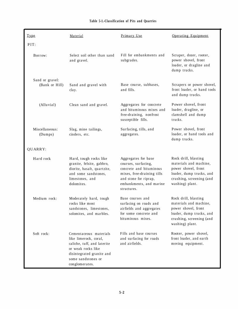
Table 5-1.-Classification of Pits and Quarries
Type Material Primary Use Operating Equipment
PIT:
Select soil other than sandand gravel.
Fill for embankments andsubgrades.
Scraper, dozer, rooter,power shovel, frontloader, or dragline anddump trucks.
Borrow:
Sand or gravel:(Bank or Hill) Sand and gravel with
clay.Base course, subbases,and fills.
Scrapers or power shovel,front loader, or hand toolsand dump trucks.
Power shovel, frontloader, dragline, orclamshell and dumptrucks.
Power shovel, frontloader, or hand tools anddump trucks.
(Alluvial) Clean sand and gravel. Aggregates for concreteand bituminous mixes andfree-draining, nonfrostsusceptible fills.
Miscellaneous:(Dumps)
Slag, mine tailings,cinders, etc.
Surfacing, tills, andaggregates.
QUARRY:
Hard rock Hard, tough rocks likegranite, felsite, gabbro,diorite, basalt, quartzite,and some sandstones,limestones, anddolomites.
Aggregates for basecourses, surfacing,concrete and bituminousmixes, free-draining tillsand stone for riprap,embankments, and marinestructures.
Rock drill, blastingmaterials and machine,power shovel, frontloader, dump trucks, andcrushing, screening (andwashing) plant.
Rock drill, blastingmaterials and machine,power shovel, frontloader, dump trucks, andcrushing, screening (andwashing) plant.
Rooter, power shovel,front loader, and earthmoving equipment.
Medium rock: Moderately hard, toughrocks like mostsandstones, limestones,solomites, and marbles.
Base courses andsurfacing on roads andairfields and aggregatesfor some concrete andbituminous mixes.
Soft rock: Cementaceous materials Fills and base coursesand surfacing for roadsand airfields.
like limerock, coral,caliche, tuff, and lateriteor weak rocks likedisintegrated granite andsome sandstones orconglomerates.
5-2

exposed to the atmosphere, it undergoes a physical andchemical process called WEATHERING, which, over asufficient length of time, disintegrates and decomposesthe rock into a loose, incoherent mixture of gravel, sand,and finer material.
Soil Quality
The intended use of the soil is the determining factorin the quality required. In general, soil used for fills andsubgrades do not have to meet the same specificationsas those used for compacted rock surfaces, base courses,or pavements.
Seven properties of rock are used to help select rockand aggregates for construction. Briefly, these rockproperties are as follows: toughness, hardness,durability, chemical stability, crushed shape, surfacecharacter, and density. Toughness, hardness, anddurability are commonly checked in the field with asimple field test.
Hardness is the resistance of a rock to scratching orabrasion. This property is important in determining thesuitability of aggregate for construction. Hardness canbe measured using the Mob’s scale of hardness (table5-2). The harder the material, the higher its number onthe Moh’s scale. Any material will scratch another of
Table 5-2.-MOH’S Scale of Hardness
Mineral HardnessDiamond . . . . . . . . . . . . . . . . 10Corundum . . . . . . . . . . . . . . . 9Topaz or beryl . . . . . . . . . . . . . 8Quartz . . . . . . . . . . . . . . . . . . . . . 7Feldspar . . . . . . . . . . . . . . . . . 6Apatite . . . . . . . . . . . . . . . . . . 5Fluorite . . . . . . . . . . . . . . . . . 4Calcite . . . . . . . . . . . . . . . . . . 3Gypsum . . . . . . . . . . . . . . . . . . 2Talc . . . . . . . . . . . . . . . . . . . . 1
ExpedientsPorcelain . . . . . . . . . . . . . . . . 7.0Steel file . . . . . . . . . . . . . . . . . . 6.5Windowglass . . . . . . . . . . . . . . 5.5Knife blade . . . . . . . . . . . . . . 5.0Copper coin . . . . . . . . . . . . . . . . 3.0Fingernail . . . . . . . . . . . . . . . . . 2.0
equal or lesser hardness. In the field, hardness may bemeasured using the common expedients shown in table5-2; for example, when you are able to scratch a rockwith a knife blade, the rock has a hardness of 5.0 or less.A rock which can be scratched by a copper coin has ahardness of 3.0 or less.
Aggregates for general construction should have ahardness of 5 to 7 and should be difficult or impossibleto scratch with a knife. Material with a hardness greaterthan 7 should be avoided since they cause excessivewear to crushers, screens, and drilling equipment.Material with a hardness of less than 5 may be used ifother sources of aggregate prove uneconomical.
The requirements as to toughness, durability,crushed shape, and other properties vary according tothe type of construction. Chemical stability has specificimportance when considering aggregates for concrete.Several rock types contain impure forms of silica thatreacts with alkalies in cement. This reaction forms a gelthat absorbs water and expands to crack or disintegratehardened concrete. These reactive materials may beincluded in some gravel deposits as pebbles or ascoatings on gravel. Potential alkali-aggregate reactionsmay be anticipated in the field by identifying the rockand comparing it to known reactive types or byinvestigating structures in which the aggregate has beenused. Generally, light-colored or glassy volcanic rocks,chert, flints, and clayey rocks should be consideredreactive unless proven otherwise.
An additional property of rock is gradation (fig.5-1). This property is also important for evaluating rockas possible construction material. Gradation is thedistribution and range of particle sizes that are presentin, or can be obtained from, a deposit. The gradation ofpit materials can be readily determined from a simpletest. Quarry materials may be more difficult to evaluate.
Figure 5-1.-Types of soil gradation.
5-3

Figure 5-2.-Conventional graphic soil symbols.
Normally, the upper limit ofparticle sizes available is controlled bythe thickness of rock layers and thespacing of cracks or fractures in therock. The amount of fine particlesproduced during rock crushing operationscan be highly variable. Generally, hard,tough rocks produce few fines, and soft,weak rocks produce large quantities offines. Weak sandstones and granitesusually produce large amounts of sand-sizematerials.
Types of Quarry Material
Natural sand and gravel are notalways available, and it is sometimesnecessary to produce aggregate byquarrying and processing rock. Quarryingnormally is performed only where othermaterials of adequate quality and sizecannot be obtained economically.
Many rock types suitable forconstruction exist throughout the world;therefore, the quality and durability ofthe rock type selected depends on localconditions. The following rock types aregenerally easy to quarry, durable, andresistant to weathering, When these arenot available, it may be necessary to usesofter rocks for base courses andsurfacing on a temporary basis. The softer
rocks will usually require little or nob l a s t i n g .
Granite. As a dimension stone,granite is fairly durable and has atexture and color desirable for polishing.As a construction material for basecourses and aggregate, it is not asdesirable as some of the more dense, fine-grained igneous rock.
Felsite–Rhyolite. This is durableand makes a good aggregate for basecourses. It is not suitable for concreteaggregate.
Gabbro-Diorite. Gabbro and dioriteboth have good strength and durability.The mineral crystals of both rocks aredeeply intermeshed, making them very toughand excellent for construction aggregate.
Basalt. The dense variety of basalt,when crushed, is excellent for use as abase course. It is very strong and durable.
Sandstone. Few sedimentary rocks aredesirable for construction due to theirvariable physical properties; however,sandstone is generally durable. Because ofthe variable nature of the types of grainsand cement, each deposit must be evaluatedind iv idua l l y .
5-4

Figure 5-3.-Sieve sizes.
Limestone. Limestone is widely usedfor road surfacing, in concrete, and forl i m e .
Gneiss. Most varieties of gneisshave good strength and durability and makegood road aggregates.
Quartzite. Quartzite is both hardand durable. Because of these qualities,it is an excellent rock for construction,although it is often difficult to quarry.
Marble. The texture and color ofmarble make it very desirable fordimension stone, and it can be used forbase course or aggregate material.
Sieve Analysis
Soil is composed of particles ofvarious sizes and composition. Figure 5-2shows the major types of soils. Soil canbe analyzed by size by sifting a dried andweighed sample through a set of testingsieves (fig. 5-3) and weighing thematerial retained on each screen. Furthertesting may be required by thespecifications for the product you need toproduce. These tests are normally
performed by the soil laboratory in theengineering department of the battalion.
Soil is classified according to theparticle size, such as coarse aggregate,fine aggregate, and mineral filler. Themaximum size of the aggregate varies,depending upon the constructionspecifications. Particle size is definedby passing a soil mass through severalsieves with different sized openings (fig.5 -3 ) .
Particles that pass through a givensieve are said to be passing that sievesize. Particles that fail to pass througha given sieve are said to be retained onthat sieve. The sieve permits particlessmaller than the opening to fall throughand retains the larger particles on thesieve. When you use sieves with screenopenings of different sizes, the soil canbe separated into particle groups based ons i z e .
A weighted sample of aggregate isplaced in the top sieve, and the entireset of sieves (largest on the top,smallest on the bottom) is vibrated eitherby hand or mechanically. The individualweights are calculated as a percentage ofthe total weight, as shown in thefollowing example: Assume we take 3,000grams of soil mass and determine how muchaggregate passes each sieve.
Aggregate passing 1/2-inchsieve and retained on3/8-inch sieve = 720 grams = 24%
Aggregate passing 3/8-inchsieve and retained on No. 4s ieve = 600 grams = 20%
Aggregate passing No. 4sieve and retained onNo. 10 sieve = 450 grams = 15%
Aggregate passing No. 10sieve and retained onNo. 40 sieve = 570 grams = 19%
Aggregate passing No. 40sieve and retained onNo. 200 sieve = 420 grams = 14%
Aggregate passingNo. 200 sieve = 240 grams = 8%
3,000 grams = 100%
The above percentages are one way ofexpressing the gradation of a sample ofaggregate.
5-5

Figure 5-4.-Sieve analysis.
5-6

Figure 5-5.—Compactive soil.
Another method, more commonly used, is toexpress the gradation in terms of the T O T A LPERCENTAGE that passes each sieve. This isdetermined by adding the listed percentage that passedeach sieve and was retained on the next finer sieve tothe percentages listed beside each of the sieves belowit.
For example, in the sample just analyzed, 24%passed the 1/2-inch sieve and was retained on the3/8-inch sieve. The total percentage that passed the1/2-inch sieve is 24% + 20% + 15% + 19% + 14%+ 8% = 100%
The total percentage that passed the 3/8-inch sieveis 20% + 15% + 19% + 14% + 8% = 76%.Continuing the calculation as indicated, the results of thetest in terms of total percentage passing each sieve areas follows:
Aggregate passing 1/2-inchsieve = 3,000 grams = 100%
Aggregate prosing 3/8-inchsieve = 2,280 grams = 76%
Aggregate passing No. 4sieve = 1,680 grams = 56%
Aggregate passing No. 10sieve = 1,230 grams = 41%
Aggregate passing No. 40sieve = 660 grams = 22%
Aggregate passing No. 200sieve = 240 grams = 8%
Figure 5-4 shows the aggregate gradation curve forthis particular example, plotted by using the abovepercentages.
For bituminous aggregate, anything that passes theNo. 4 sieve and is retained on the No. 200 sieve is
considered FINE aggregate. Anything retained on theNo. 4 sieve is considered COARSE aggregate.
Material that can pass a No. 200 sieve is sometimesused in bituminous paving; this material is known asMINERAL FILLER, DUST, OR FINES. It consists offinely powdered rock, portland cement, hydrated lime,or some other artificially or naturally powdered dust.
All testing sieves larger than three-sixteenths of aninch are identified by the actual clear opening in inches.All testing sieves smaller than three-sixteenth of an inchare identified by mesh number. (See fig. 5-4.)
Compaction Qualities of Soil
Compaction is the process of physically densifyingor packing the soil. The strength of any given soil canbe increased by the densification obtained fromcompaction.
Three factors affect compaction: materialgradation, moisture content, and compactive effort.
Material gradation (fig. 5-1) refers to thedistribution of different sizes of particles within a givensoil sample. A well-graded sample contains a good, evendistribution of particle sizes. When the composition ofa soil sample is made up mostly of one size of particles,this soil would be poorly graded. A well-graded soil willcompact more easily than one that is poorly graded. Inwell-graded material, the smaller particles tend to fill theempty spaces (voids) between the larger particles,leaving fewer voids after compaction (fig. 5-5).
Moisture content is the amount of water present inthe soil. Because water acts as a lubricant that helpsparticles slide into a denser position, the moisturecontent of a soil is very important to compaction. Wateralso helps bond clay particles, giving cohesive materialstheir sticky qualities.
5-7

Figure 5-6.—Soil compaction test graph.
Experience has shown it is next toimpossible to achieve proper compaction inmaterials that are too dry or too wet. Soilexperts have proved that in every soilthere is an amount of water, called theOPTIMUM MOISTURE CONTENT, at which it ispossible to obtain maximum density with agiven amount of compaction. Figure 5-6 isan example of a compaction curve that isused to show the relationship between drydensity and moisture content. The soillaboratory performs and determines theoptimum moisture content.
Compactive effort is the method bywhich the compactor imparts energy into
the soil to achieve compaction. Compactorsare designed to use one or a combinationof the following types of compactiveeffort: static weight (pressure), kneadingaction, impact, or vibration.
PIT OR QUARRY SITE PREPARATION
Preparation of a new site shouldstart immediately after the site locationhas been selected. Preparatory workincludes making an operations plan,clearing the site, removing overburden,draining the s i te , bui ld ing
5-8

roads, loading ramps, and installing processingequipment.
Operations Plan
The operations plan is prepared before any earth ismoved. The plan includes the limits of the site to bedeveloped, methods of excavation, equipment to beused, number of personnel required, and locations ofroads, structures, and support equipment. Also, plans fortraffic control and drainage are established.
Clearing the Site
When the site is located in a wooded area, the firstoperation is to clear all timber, standing or fallen. Ifcamouflage is necessary, trees or brush outside thedesignated cleared area should not be removed.
Construction equipment operations are usually themost rapid and efficient means of clearing a site. Use ofthe equipment is limited only by unusually large treesand stumps–terrain which hinders their maneuverabilityand maintenance requirements. The constructionequipment used include bulldozers, winches, powersaws, rippers, motor graders, and scrapers. In addition,hand tools are used in certain clearing operations.
Brush may be disposed of by burning on the site;however, check to see if a burn permit is required.Timber of suitable dimensions should be stockpiled atthe perimeter of the site. This timber should be saved forpossible use in construction of loading ramps. Allstumps, roots, boulders, vegetation, and rubbish must beexcavated and moved clear of the site.
building access roads, and leveling stockpile andequipment sites.
In excavating aggregates for concrete, bituminousmixtures, or base courses, the overburden must beremoved while the aggregates are processed. Frozenmaterial is loosened either with a ripper or explosives.Overburden should be kept cleared at least 50 feet backfrom the top of the face of a quarry or pit to prevent rockand other material from falling on personnel workingnear the top of the face. Also, overburden should becleared far enough back from the top so the equipmentbeing used to clear the overburden does not interferewith drilling operations.
RoadsOverburden
Drainage
Adequate drainage is essential to the operation of apit or quarry. Alluvial gravel pits may be worked wet ordry, depending on water levels. Borrow pits and quarriesare normally worked dry.
Drainage facilities are installed as early as possibleso the site will be dry when work starts. The means ofdrainage depends primarily upon the location and theamount of water to be eliminated. Hillside locations areeasy to drain by an interceptor ditch made along theuphill side with a scraper, dozer, or grader. When thefloor of a site is belowground level, both surface andseepage water must be disposed of. When open ditchescannot be dug to take advantage of gravity flow, allwater is directed to a sump hole. A slight slope on thesite floor must be maintained at all times to permit waterto drain away from the working face of the site.
Overburden is usually removed from a pit or quarrysite by a continuous process of stripping. The methodsand equipment used in removing overburden aredependent upon the type of excavation planned, thedepth of overburden, and the distance the overburdenmust be moved. It may be advantageous to leave inplacethe overburden at military quarry sites and blast it withthe rock to provide binder for road building materials.Removal is coordinated with excavation to provide acontinuously cleared area. The spoil should be dumpedin a remote area to avoid double handling. On hillsidelocations, the spoil should be placed in banks, locatedon the downhill side, outside the working area.
Remember that all overburden is not necessarilywaste. Some of the overburden is suitable for filling,
Construction of access roads should start as soon asthe operations plan is completed so they are ready foruse when the pit and quarry equipment arrives. Theaccess roads should be designed for all-weatheroperation under the heaviest loads anticipated. Theroads should follow the shortest and easiest routes thatsatisfy the traffic control plan. To speed up hauling, youmust avoid sharp curves and grades kept as low aspossible. Ten percent grade (10-foot drop or climb every100 feet) is the maximum grade for truck operations,whereas tractors and graders can climb 20-percentgrades for short distances.
Except for the loop at the loading site, access roadsshould provide one-way traffic—one route to enter andanother to haul out. Leave enough space between haulroads and borrow pits to avoid traffic hazards.
5-9

Figure 5-7.-Plain chute loading ramp.
Chute Loading Ramps
A chute loading ramp
Figure 5-8.-Layout and development of a scraper pit.
are unavailable. An elementary type of loading ramp isthe plain chute (fig. 5-7). Each ramp must be able to
is an expedient means of support the heaviest equipment used, plus an impactloading excavated material into trucks with earth factor of 50 percent, and approximately 20 ton; ofmoving equipment at sites where loaders and clamshells material.
5-10

Figure 5-9.-Layout and development of a pit, using a dragline.
PIT OPERATIONS
Sand, gravel, and other construction materials areextracted from pits with scrapers that can move hugevolumes of material in a relatively short period of time.The material is removed from the floor of the pit insuccessive thin layers over its entire width.
During excavation, scrapers should be carefullyspotted to maintain an even downgrade and preventcutting holes below the general level of the pit floor.When the pit is longer than 100 feet in the direction ofloading, the scraper spots should be staggered along thelength of the cut as well as across the width of the zone.Figure 5-8 depicts the layout and development of ascraper pit with lines A-A and B-B showing the limitsof the pit. Lines A-A and B-B divide the area into threezones for current excavating, stripping, and clearing.Zone 1 is being excavated at the same time Zone 2 isbeing stripped and Zone 3 is being cleared. Threescrapers in staggered formation load downhill in Zone1, and a dozer strips downhill in Zone 2.
In consolidated gravel or soft rock, when scrapersassisted by pusher tractors (Push Cat) will not pickup aheaping load within 150 feet, a ripper should be used toloosen the material, thereby increasing the loadingefficiency of the scrapers. Rippers should be operateddownhill, and an entire zone should be ripped at one timewhile the scrapers are hauling from another zone.
The dragline is the most practical piece ofconstruction equipment for underwater digging and isparticularly adapted to submerged gravel pit operations.Draglines can efficiently recover sand, gravel, laterite,or coral from beaches, the beds of streams, and thebottoms of lakes and lagoons. Figure 5-9 depicts thelayout and development of a pit being excavated with adragline.
Clamshells are capable of excavating loose sand,gravel, and crushed stone at, above, or below groundlevel. The clamshell can be raised and loads dumped atheights equal to the distance from the tip of the boom tothe ground, minus the length of the clamshell bucket, toallow adequate clearance for the bucket when it isopening.
Material removed from pits can seldom be used inits inplace state. In most cases, pit material must beprocessed (crushed and screened) to meet jobspecifications. But, before the material can beprocessed, it must be loaded and delivered to theprocessing equipment. Loading and delivery mayrequire additional handling equipment, such asfront-end loaders equiped with either a rollback bucketor 4-in-1 bucket and conveyers that may be used singlyor in series to load vehicles, construction equipment, orhoppers from stockpiled material. Bucket loaders mayalso be used. They consist of a power-driven endlesschain to which buckets are attached so material is loadedon the downward travel. Handling equipment is used to
5-11

Figure 5-10.–Quarry terminology.
Figure 5-11.–Typical quarry layout.
5-12

load stockpiled material into overheadhoppers and trucks.
The production of any pit materialthat requires crushing and screeningdepends on the capacity of the processingequipment used.
QUARRY OPERATIONS
Quarrying involves not onlyextraction of material (rock) but alsocrushing and screening that makes therock suitable for use as constructionmater ia l .
Quarry Terminology
Figure 5-10 shows the names ofvarious quarry features. Overburden isthe waste material that often overliespit or quarry sites. Deposits withinthe waste materials are called spoil andmust be removed before excavation ofthe construction materials lyingbelow. Overburden refers to loosematerial but locally it may includesolid rock lying above the desiredmaterial. Burden is the constructionmaterial on the face of a quarry. Thefloor of the quarry is the inside bottomsurface that marks the lower limit ofexcavation. Often quarries contain oneor more working floors at various levelsabove the final quarry floor. A quarrywall is a more or less vertical surfacethat marks the lateral limit ofexcavation. The face of a quarry is arock surface (usually vertical) fromwhich rock is to be excavated. The topof the face is called the crest, and thebottom is called the toe. A bench is asteplike mass of rock behind a faceand below a working floor, Notice thateach bench has a face, toe, and crest.
Quarry Development
The layout of a quarry shouldprovide a gravity flow of material fromthe face to the crusher, from the crusherto the storage bin, and from the bin tothe hauling equipment, as illustrated infigure 5-11. A quarry laid out in thismanner assures that a maximum quantity ofrock can be processed with a minimum oflabor and equipment. In quarries laid outon the gravity-flow principle, thedrainage problem is practicallyeliminated.
Military quarries are generally ofthe open-face type with the verticalsurface of the rock exposed. Depending
Figure 5-12.-Determining the direction of thequarry face.
upon local conditions, they may be developedby the single- or multiple-bench method.
Where the rock face is not exposed,core samples should be taken in a gridpattern so rock formations can be plotted,and the lay of the strata, the quality andquantity of the deposit, and depth ofoverburden can be determined. Should arock formation be jointed or stratified,the layout of the quarry is determined bythe strike (direction) of the formation;that is, the face of the quarry must bedirected at right angles to the strike(fig. 5-12). This ensures a vertical ornear vertical face with less chance ofundercutting the face and creating adangerous overhang.
5-13

Figure 5-13.-Single-bench quarry.
A single-bench quarry (fig. 5-13) is one having theentire floor on one level. The height of the bench willdepend on the reach of the equipment available. In theNCF, the recommended bench height is 10 feet;however, depending on the drilling equipment available,type of rock, magnitude of operation, and experience ofthe operating personnel, bench heights can range from8 to 40 feet.
Military quarries are usually of the single-benchtype. This type offers greater safety and efficientoperation. All operations are on one level, a greateramount of rock is shot at one blast, and less equipmentis needed in the overall process. In addition, this typeof quarry requires less training for the operatingcrews.
Blast trial shots are made in both existing and newquarries before installing equipment for two reasons.First, to avoid possible damage to installed equipmentand the second, in the case of new quarries, is that thetrial shots will provide necessary ballast to construct
access roadsupon.
and for foundations to place equipment
WARNING
Blasting must be supervised and controlleddirectly by a qualified blaster. Also, allpersonnel working around blasting should wearhard hats, safety goggles, dust respirators,earplugs, and hard toe safety shoes.
A multiple-bench quarry (fig. 5-14) is one having aseries of ledges or terraces resembling steps. The highestbench is blasted and worked first. Then successive lowerlevels are simultaneously developed as the workprogresses and as each bench is required.
Quarries are developed by the multiple-benchmethod when the face is too high for single shots,horizontal seams or separations are present, or deep andnarrow deposits exist. This method of developmentpermits equipment to be used simultaneously at more
5-14

Figure 5-14.-Multiple-bench quarry.
than one level. All benches must be made wide enoughto allow the use of equipment to remove blasted rock(50 feet minimum). Multiple-bench quarries makepossible greater continuity of operation thansingle-bench quarries.
NOTE: When you are developing a multibenchquarry, blasting must be confined to only one bench ata time. Simultaneous blasting at several levels is NOTpermitted under any circumstances.
QUARRY EQUIPMENT
CESE is available in the Naval Construction ForceTOA to enable construction units to meet their ownaggregate production requirements. Quarry equipmentis subject to exceptionally hard wear due to the abrasiveaction of rock and rock dust; therefore, the operator’smaintenance procedures contained in themanufacturer’s maintenance and service manuals mustbe strictly followed.
The equipment used in hard-rock quarriesconsists of bulldozers, air compressors, rock drills,drill steel and bits, loading and hauling equipment,and miscellaneous tools. As the supervisor in chargeof quarry operations, you must ensure that operator’smaintenance is performed and that all cutting edges,end bits, teeth and shanks, dozer tracks, tires, blades,and so forth, are checked daily for wear, adjustments,and cracks.
Wearfacing
Equipment used in quarry operations should bewear-faced. Wearfacing greatly extends the usable lifeof construction equipment, ensures efficient operationwith less downtime, and greatly reduces the need forspare parts. Guidelines for wearfacing equipment partsand accessories are outlined in the NCF WeldingMaterials Handbook, NAVFAC P-433.
5-15

Wearfacing is commonly known in the NCF ashardfacing. The purpose of hardfacing (fig. 5-15) is toinsulate many working parts of equipment from thedestructive forces that cause metal wear. The selectionof a hardfacing alloy for a certain application is basedon the capacity of the alloy to withstand or resist impactand abrasion. Impact refers to a blow or series of blowson a surface that results in a fracture or gradualdeterioration. Abrasion is the grinding action that resultswhen one surface slides, rolls, or rubs against another.Under high compressive loads, this action can result ingouging.
Alloys that resist abrasion well are poor inwithstanding impact, whereas those that withstandimpact well are poor in resisting abrasion; however,there are many alloys whose hardfacing properties fallbetween two extremes. These alloys offer someprotection against abrasion and withstand impact fairlywell. The hard-faced welding procedures, the typematerial the part is manufactured from, and the primaryand alternate electrodes to perform the hardfacingprocedures are all outlined in NAVFAC P-433.Hardfacing operations must be approved by themaintenance supervisor.
Maintenance
Often, maintenance is put off to a later date becauseof production. This may satisfy the immediateproduction demands of the unit, but it is not good for the
equipment and creates a lax attitude toward scheduledmaintenance. When this occurs, a precedent is set thatleads to putting maintenance second to production.Should this happen, it is not long before production ratesdecline because of equipment breakdowns.
BLASTING OPERATIONS
Blasting operations are usually necessary whenworking a quarry containing materials that cannot beremoved with construction equipment, such as front-endloaders, bulldozers, and hauling equipment. Should thisbe the case, blasting will come under the directsupervision and control of a qualified blaster who carriesthe NEC-5708. All other quarry personnel assignedmust follow written and oral instructions, carry outassigned duties, and observe all safety precautions.
Limiting the number of personnel handlingexplosives lessens the risk of accidents occurring. Thismeans one or two blasters have a definite assignment toconduct several of the tasks involved in loading andfiring a blast. These tasks include the following:carrying explosives and detonators, opening cases,priming, loading, stemming, connecting blastingcircuits, and firing. The entire quarry crew must knowexactly what the blaster’s duties are. With such a systemobserved, everything is accomplished in a precise andorderly manner with no haphazard assumption of thevarious tasks to be performed.
5-16

Figure 5-15.
5-17


CHAPTER 6
CRUSHER SUPERVISOR
Equipment is provided by the Naval ConstructionForce (NCF) to enable the Seabees to meet aggregateproduction requirements. Of this equipment, crushing
equipment is the critical item that provides thecapability to reduce and process material from a pit orquarry to produce finished aggregate in sufficientquality and quantity to meet constructionrequirements.
Seabees are tasked with crusher operations in bothPacific and Atlantic fleet deployment sites. The NavalConstruction Training Center (NCTC), Port Hueneme,California, provides training for crusher operations;however, the majority of training in this area is achievedthrough on-the-job-training (OJT).
The COMSECOND/COMTHlRDNCB direct thetasking of crusher operations conducted by the NavalMobile Construction Battalions (NMCBs). TheNMCBs schedule a predetermined number of man-daysfor crushing a variety of sizes and volumes of materialused to support construction projects, concrete plants,crete mobiles, and asphalt plants. At the end of adeployment, each battalion involved is usually taskedto turn over a specified number of cubic yards ofmaterial of various sizes to the relieving battalion. Themagnitude of the rock crusher tasking dictates the sizeof the crew assigned to support the rock crusheroperations.
CRUSHER SUPERVISORRESPONSIBILITIES
In the Naval Construction Force (NCF), crusher
operations are usually managed by Alfa company. TheAlfa company operations chief is responsible forcrusher operations and should assign a crushersupervisor to direct the operations of the crusher. Thischapter presents important information an EO mustmaster to gain the basic knowledge of rock crusher
operations required to perform the duties of a crushersupervisor.
ROCK CRUSHER
Crushing plantsoutput. The most
are classified by their capacityoften used plant, classified
medium-to-large, has a rated capacity of 75 tonsper hour (tph). This plant has two separate anddistinct sets of equipment: the primary unit andsecondary unit.
The primary unit reduces the quarry rock or coarsegravel by crushing. The secondary unit is primarily usedto process the crushed product.
The amount of crushing required to produce asuitable amount of aggregate material depends upon theavailability of raw materials and the specificationsestablished for the end product. In any crusheroperations, there are four basic functions thathave to be accomplished. The four functions are asfollows:
1. Particle size reduction by crushing.
2. Separation into particle size ranges byscreening.
3. Elimination of undesirable materials bywushing.
4. Movement of the material from one location toanother.
Primary Unit
The primary unit (fig. 6-1) consists of a20-inch by 36-inch standard type of jaw crusher(fig. 6-2), a vibrating grizzly, an under crusherdelivery conveyor, and a running gear. The jawcrusher can be powered by a diesel engine or byelectrical power. All other components are driven byindividual electric motors. Normally, power issupplied by a 200-kW diesel generator. The runninggear is equipped with a fifth wheel and towingdolly.
CAUTION
Make certain each electrically poweredcomponent is grounded.
6-1

Figure 6-1.-Primary unit.
Most crusher and screening units plants are
equipped with some type of feeder to regulate the flowof material into the crusher unit. A heavy-duty apron
type of feeder (fig. 6-3) is usually used to feed theprimary crusher. Raw materials from the pit or quarry
are deposited into the hopper of the heavy-duty apron
feeder that moves the material onto the deck of the
vibrating grizzly. The rate of flow of the feeder belt is
controlled by the operator using the START and STOPbuttons located on the control panel.
Figure 6-2.-Jaw crusher.
As material is moved out of the apron feeder, it isprocessed across the vibrating grizzly. The deck isnormally a bar type of screen with a 1 1/2-inch fixedopening. It screens out material smaller than 1 1/2 inchesand routes the oversized material through the jawchamber to be crushed. The undersized material isrouted through a chute to the undercrusher conveyer.From this point the material can join the jaw crusherproduct by closing a flop gate. This material can bedirected through another chute (by closing a flop gate)and routed to a by-product stockpile.
The vibrating grizzly prescreens material that isalready down to size, allowing the material to bypass thejaw crusher. The grizzly also dry-cleans the material byvibrating it vigorously. The flop gates on the grizzlyenable the operator to select and decide what to do withsmaller particles.
Oversized material is routed through the jawcrusher where it is gradually reduced in size by a seriesof elliptical- downward crushing strokes and is thendischarged onto the undercrusher delivery conveyerbelt. The product size is determined by the productsetting adjustment made at the discharge end of the jawplates.
The hourly rate of production to be obtained from agiven size jaw crusher depends upon a number ofvariable factors:
1. The toughness of the raw material.
2. The product setting.
3. The reduction ratio. (The size of the material fedto the crusher compared to the product size.)
6-2

Figure 6-3.-Apron feeder.
4. The gradation of raw material.
5. The extent of wear to the corrugated surfaces ofthe jaw plates.
6. The rate of feeding.
Feeding problems may develop due to irregularshapes and unwieldy nature of quarry run rock. Feedingproblems can drastically reduce production. Somecommon problems are blocking, bridging, choking, andpacking.
Blocking occurs when an oversize rock settles overthe jaw opening and stops the flow of incoming material.The jaw continues to operate but no crushing takesplace. To prevent blocking, you should let the maximumsize of material processed be 2 inches less than the jawcrusher size. Blocking can be controlled or eliminatedby using a scalping grizzly to prescreen material. Foroptimum production, the ideal feed size is 75 percent ofthe jaw size.
Bridging occurs when two rocks, within themaximum size, arrive at the same time. The two rocksinterlock and bridge the jaws open. When this occurs,all production stops. When large rocks approach theopening, they should be fed individually to preventbridging.
Chokingcontinually
occurs when the jaw chamber isoverfilled. This creates an overload
condition and causes the engine to lug down and may
damage the equipment. For optimum production, theoperator should try to keep the jaw chamber 75 percentfull.
Packing occurs when feed material cakes and packsin the crusher chamber. Plastic material, such as clay,may become sticky and cause this problem. Packing canbecome so severe that it completely stops production.Packing can be reduced or eliminated by prescreening
or prewashing the material. In most cases, the mostpractical solution is to wet down the material
thoroughly. Then process the material even though it isalmost in the form of a slurry.
The jaw crusher can produce at a rate of 55 to 185
tph, depending upon the product setting and the
toughness of the material being crushed. The maximumproduct setting is 5 inches, and the minimum setting is1 1/2 inches.
WARNING
Keep all parts of your body out of the jaw
cavity when you are operating or adjusting thejaws.
6-3

Figure 6-4.-Secondary unit.
Secondary Unit
The secondary unit (fig. 6-4) consists of a
reciprocating feed hopper, an overcrusher conveyer, a
two-deck vibrating screen, a dual roll crusher (fig. 6-5)or hydrocone crusher (fig. 6-6), an undercrusher return
conveyer, a revolving elevator wheel, a diesel powerunit, and the running gear. The dual roll or hydrocone
crusher can be driven by a diesel engine or an electric
motor. All other components are driven by individual
electric motors and power is normally supplied by a
200-kW generator.
Material to be processed is introduced into thehopper of the reciprocating feeder. The rate of flow iscontrolled by the adjustable gate opening. Material isdeposited onto the overcrusher conveyer and carried tothe feed end of the top screen. Material that has beencrushed down to product size by the jaw crusher passesthe top screen. Oversized material is retained on the topscreen and directed through a dual roll crusher orhydroccme crusher for further reduction.
The dual roll crusher consists of a set of rolls thatrevolve toward each other at a constant rim speed. Stoneparticles are reduced in size as they are drawn betweenthe two rolls. Product setting is determined by the
Figure 6-5.-Dual roll crusher.
6-4

Figure 6-6.-Cone crusher plant.
6-5

spacing between the rolls. It is necessaryto set the opening between the rollsslightly closer than the top product sizerequired. With two coarse corrugatedshells (fig. 6-7), the tip-to-tip settingproduces a product larger than two smoothshells set at the same distance.
In the NCF, the hydrocone crusher isnormally used as the secondary unit. Thesemachines have a conical or domed crushingmember called a cone, head, or sphere,which moves in a small circle around avertical axis inside a fixed bowl ormantle.
The cone may be relativelystationary at the top and move at thebottom only, or be mounted so that thehead can wobble as well as gyrate. Thecrushing head is free to turn under thethrust from the material being crushed.The fineness of the product is adjusted byraising or lowering the mantle.
Effective feed and dischargearrangements are essential to theoperation of any cone type of crusher. Formaximum crushing efficiency, feed must besupplied to the crushing chamber in theoptimum amount and distributed evenlyaround the entire crushing area.
NOTE: Material received by thehydrocone crusher must be evenly distributed
nonsegregated feed. This means that thematerial entering the crusher is evenlydistributed around the entire crushingchamber, with fine and coarse materialwell intermixed in the feed. Unevenlydistributed or segregated feed resultsin poor manganese wear, reducedcapacity, and high stresses within thecrusher. These problems can cause shortbearing life and possible failure ofmajor components. An evenly distributed,nonsegregated feed results in maximumcapacity, a uniform product, and asmooth running machine.
A pressure gauge is standard on allhydrocone crushers. Erratic hydroset controlpressure and motor amperage (horse-powerdraw) readings are evidence of poorfeeding conditions and uneven feeddistribution in the crushing chamber. Thepressure gauge enables the operator toread high, average, and low pressures inthe hydroset control and take correctivemeasures against erratic and high-pressureconditions. The pressure gauge should bechecked regularly when the crusher isreceiving the full or maximum amount offeed.
NOTE: When excessive fluctuations occurin the pressure in the hydroset control andhorsepower drew, determine and eliminate thecause immediately. Operating the crusherunder these conditions can cause
Figure 6-7.—Shell combinations for dual roll crushers.
6-6

excessive shock loading and may result in seriousdamage to the crusher.
All hydrocone crushers are supplied with a feedhopper with an adjustable feed spout that is adjustableboth vertically and horizontally. Horizontal adjustmentof the spout is accomplished by moving the adjustablefeed spout frame on the feed hopper. Slotted holes in theupper flange of the feed hopper, and in the feed spoutframe, allow the feed spout to be moved horizontally inorder to position it properly over the feeder plate orspider cap. The feed spout can be positioned verticallyby using studs and adjusting nuts to fasten the spout tothe frame. The vertical position of the spout controls theamount of feed going into the hydrocone crusher.
Adjustable feed spout frame construction allows themounting of a suitable feedbox. Normally, it is better tohave the incoming feed hit the side of the feedbox, afterwhich it falls vertically through the feed spout. This isthe most effective way of obtaining proper feed to thehydrocone crusher (fig. 6-8).
The discharge arrangement setup must allow thematerial to discharge freely without backing upunderneath the crusher. Material backing up below andinto the hydrocone crusher can result in serious damageto the machine.
A straight-down discharge is commonly used withhydrocone crushers. With this arrangement, crushedmaterial falls into a stone box below the crusher.
Material passes through a hole in the stone box flooronto a conveyer belt that carries it away. This dischargearrangement helps prevent buildup of sticky materialsbeneath the crusher.
The crushing chamber is annular (ring shaped).Rock fed into the top falls between the cone andthe mantle and is crushed as the opening narrows withthe movement of the cone. When the opening widensagain, the pieces fall farther, to be crushed againas the cone gyrates. The crushing action is similar tothat of a jaw crusher, except the squeeze comes from theside rather than from the bottom and the curve of thejaws.
The cone speed and the distance of travel mustbe carefully synchronized. A wide space allowspieces to fall more freely than a narrow one when thecone is moving slowly; however, it allows pieces to falltoo far before the next impact. On the other hand, wherethe space is narrow and the cone is moving rapidly,the pieces cannot fall far enough and this causesproduction to be low for the amount of power beingused.
CAUTION
DO NOT operate the cone crusher at asmaller setting than that for which it wasdesigned. Operation at too small a discharge
Figure 6-8.-Recommended cone crusher feed arrangement.
6-7

setting may result in packing in the crusherchamber, high loads and stresses, and possibledamage to major components.
After passing the dual roll crusher, the material isrecirculated to the top screen by means of a returnconveyer and a revolving elevator wheel. The materialfrom the hydrocone crusher is recirculated to the topscreen by means of a return conveyer and a crossoverchute. Any material still too large to pass the top screenis routed through the roll crusher or hydrocone crusheragain. This is known as a “closed circuit” crushingsystem. It is obvious that the product setting on the rollcrusher or hydrocone crusher should be set at or slightlyless than the opening size of the top screen.
The material retained on the bottom screen is theproduct that is routed through a chute to a conveyer andthen delivered to the product stockpile. Material toosmall to meet product specifications is screened out bythe bottom screen and delivered to a by-productstockpile.
The secondary unit includes a bar type of scalpingscreen that can be inserted into the top rim of the slopinghopper. When inserted, this screen causes any oversizedmaterial to be scalped and rolled off of the screen andto the rear of the machine.
The same factors discussed for the jaw crusher alsoaffect the production of the roll crusher. By comparison,dual roll crushers have a limited “stage of reduction”capability. “Stage of reduction” is the difference,
expressed in inches or centimeters, between themaximum input and maximum output size of materialdue to a single crushing action. A stage of reduction of3 inches (7.6 cm) indicates a 3-inch (7.6-cm) reductionin maximum particle size. This reduction capability is afunction of the diameter of the rolls and of the nature ofthe roll shell surface; therefore, every different size andcombination of roll shells has a somewhat differentstage of reduction capacity. For this reason themaximum size of material to be fed to a dual roll crusheris critical.
The maximum allowable feed size is the sum of thestage of reduction capability and the product setting. Ifthe maximum feed size is exceeded, unsatisfactoryresults likely to occur are as follows:
1. Retarded production
2. Excessive roll shell wear
3. Excessive long-and-flat particles
These units also have a wide range of productioncapability. The actual rate of production in tons per houris usually determined by the screening capacity of thescreens. In some cases, the rate may be limited by thecapacity of the dual roll crusher or hydrocone crusher.
Screens
Crushed rock particles are separated into two ormore particle size ranges by the use of screens (fig. 6-9).Screens are also used to scalp off oversized rock and to
Figure 6-9.-Vibrating screen box.
6-8

screen out fines. This enables you to direct certainselected material to receive special or additionalprocessing. Certain material may also be directed tobypass processing that is not required.
Screens consist of two, three, or four layers or decksof open-mesh screen wire cloth, mounted one above theother in a rectangular metal box. The screen surfaces arevibrated to aid sorting. Material is fed at one end and isseparated into size ranges as it passes over the screeningsurface. The screening process is based upon the factthat particle sizes smaller than the screen cloth openingsize passes through the screen and oversized particlesare retained.
Stratification of the feed material must occurrapidly as the material is passed over the screen surfaceto obtain good efficiency and high capacity. This ensuresthe smaller particles can move quickly to the bottom andfall through the screen openings, and the largeroversized particles are carried to the top of the feedstream where they are retained and directed off the endof the screen. The desired performance of specificscreens is obtained by varying the degree of inclination,frequency and amplitude of stroke, and the direction ofthrow. Screens may be horizontal or inclined up to about20 degrees and vibrate at 850 to 1,250 strokes perminute, depending upon the particular application.
CAPACITY.– Capacity is the rate in tons per hourat which a screen produces (passes) the material desired.The capacity of a screen is the rate at which it separatesdesired material from the feed.
FEEDING MATERIALS TO SCREEN.– Caremust be taken to spread the flow of material evenly
across the full width of the screen. The thickness of thebed of feed material should be approximately four timesthe screen opening size. If this is exceeded, the screenbecomes overloaded and the vibrations are dampened.This results in the finer particles being unable to findtheir way to the screen wire opening. When aninsufficient amount of material is fed, the total capacity
of the screen is not used.
VARIABLE FACTORS.– Numerous factors canaffect the performance of screens. Some examples ofthese are as follows: shapes, weight, and gradation ofparticles; degree of inclination and vibration; type ofwire screen cloth; position of the screen within the deck;
and wet screening (washing).
Screen Selection
Once the gradation of material has been determined,
screens must be selected that can segregate the materials
into appropriate sizes. The number of screens to be
selected is dependent upon the number of size rangesinto which the material must be segregated and the type
of equipment available for screening. Table 6-1 givesthe screen sizes of vibrating screens used to produce
specific sizes of aggregate.
Table 61.-Vibrating Screen Selection Chart
6-9

The selection of screen sizes depends upon the sizeof the product desired. The maximum and minimumsizes of the product are expressed in the specifications.Consider the following specifications:
Size Percent Passing
1 inch 100 percent3/4 inch 90 to 100 percent1/2 inch 20 to 50 percent3/8 inch 0 to 15 percentNo. 4 0 to 5 percent
By this specification, the largest size aggregate thatis acceptable is 1 inch. Since 100 percent must passthrough the screen for 1-inch aggregate, 0 percent canbe larger than 1 inch. Although the specification saysthat the lot is acceptable with up to 5 percent of the totalproduct passing through a No. 4 sieve, it is saying thatthe No. 4 aggregate is the smallest size desired.
Based on these specifications, the plant should becalibrated to produce a product between 3/4 and 3/8inches. The reasoning behind calibrating the plant toproduce a 3/4-inch to 3/8-inch aggregate rather than a1-inch to No. 4-size aggregate is because somewhatoversize particles can pass a given screen opening sizewhen oriented diagonally.
By calibrating the plant to produce a top size of3/4-inch aggregate, you can provide a safety margin of10 percent in the event the product stockpile maycontain aggregate over 3/4 inch, but less than 1 inch. Thesame reasoning holds true on the minimum product size.Calibrate the plant to produce 3/8-inch aggregate as theminimum size, thereby creating a 15-percent leeway forparticles in the stockpile being less than 3/8 inch.Therefore, you should choose the next smaller sizescreen than the given maximum specification size forthe upper size calibration. Smiliarly, you should choosethe next larger size screen than the given minimumspecification size for the lower size calibration.
Remember: It is necessary to select screens withopenings slightly larger than the size products desired.This is due to screen inefficiency caused by thetingle of inclination, throw, and angular particleshapes.
Table 6-1 is used for the selection of screens and therelationship between product size and screen size. Forexample:
If your plant has a two-deck vibrating screen, youshould select the following screens:
Product Size Desired Screen Size Selected
Top 3/4 inch 7/8 inchBottom 3/8 inch 7/16 inch
The relationship between aggregate size and screensize is important. The required screen sizes are slightlylarger than the product sizes. If a 7/8-inch screen is notavailable, a 3/4-inch screen should be selected to be putin the unit. If a 7/16-inch screen is not available, a3/8-inch screen should be used.
Conveyers
Conveyers (fig. 6-10) are used to move materialbehg processed from one component to another and [oconvey the finished product into bins, trucks, orstockpiles. Rubber belt conveyers are of the fixed orportable type. Fixed conveyers are attached to and areacomponent of the crusher unit. They are similar indesign and work on the same principle as do portableconveyers.
Before operating conveyers, check to see that beltsare aligned and do not rub on the frame or other parts ofthe plant, As each conveyer is operated, check to see ifthe belts are ruining true. If the conveyer belt is runningto one side on the head or tail pulley, then tighten theend adjustments on that side until the belt is running inthe center of the pulleys. On new assembled conveyers,this procedure must be performed quite often during thefirst few days until the belt is trained. Even after the headand tail pulleys are set and the belts are ruining centrallyover them, a conveyer belt may ride to one side and offthe end of the troughing rolls. Should this occur, loosenthree or four troughing roll assemblies and slide the endsupward about one-fourth inch on the side to which thebelt is climbing. his action forces the belt toward thecenter of the troughing rolls. The (roughing roll frameshave slotted holes to allow for this adjustment. Thereturn roll frames have slotted holes for adjustments andmay be adjusted in the same manner as the (roughingrolls.
Make sure all troughing and return rolls are rotating.Rolls can be worn through and belts damaged if the rollsbecome jammed. The belts should be checkedfrequently to ensure the fasteners are holding and thebelts are not slashed or torn. Operating a conveyer withdefective Fasteners or belts is dangerous to personneloperating the plant and could also cause damage to otherequipment.
All conveyers are provided with wipers located nearthe tail pulley on the return run of the belt. Keep the
6-10

Figure 6-10.-Conveyer.
rubber stripping of the wipers adjusted to just makecontact with the face of the belt. This adjustmentremoves rocks from the belt, thus preventing rocks fromentering between the pulley face and inside face of thebelt.
Three factors affect the efficiency of conveyeroperation. These factors are as follows: speed, loading,and incline.
1. Speed. Most conveyers operate at a speed ofapproximately 300 feet per minute and have a capacityof approximately 300 tons of material per hour. Areduction in speed obviously reduces the conveyercapacity, and an increase in speed theoretically increasesthe capacity. An increase in conveyer speed may alsoincrease wear on the conveyer belt due to increasedslippage of the material at the loading point. An increasein speed also increases the throw of the material at thedischarge end of the conveyer. In some cases, it may benecessary to fit the end of the conveyer with a box orbangboard so the material from the belt falls properly.
2. Loading. Proper loading of a belt conveyer ismandatory for efficent operation. This includes placingthe load in a position centered on the conveyer belt. Agood practice is to load a conveyer in such a mannerthat allows the material to strike the belt in the directionof travel. When material is to be delivered from a spoutor belt to another belt from one side, a transfer box orbangboard should be provided to facilitate properdelivery on the belt. Loading a conveyer belt on one sidecauses it to run to the opposite side of the support rollerswhich results in excessive belt wear.
3. Incline. Portable conveyers can be adjusted tooperate at the various inclines required to meet jobconditions. The maximum incline is determined by the
material carried on the conveyer and varies from 12degrees for washed gravel to 20 degrees for loose earth.When the maximum angle is exceeded, slippage mayoccur.
WASH PLANT
In many types of construction operations, it is notnecessary to have washed clean aggregates in thefinished product; however, some types of operationsrequire clean aggregates free of objectionable material.The wash and screen plant (fig. 6-11) consists of ascrubber, a vibrating screen, and a screw (sand)dehydrator (fig. 6-12). In operation the raw material isfed into a scrubber designed to break loose alldeleterious material. The scrubbed aggregate and washwater are cast upon a triple deck vibrating screen for sizeseparation. The materials retained on the decks of thescreen are sent by individual chutes to their respectiveconveyers for further disposition. The wash water andsand are carried through the third deck into the well ofthe sand dehydrator, where the undesirable products areremoved from the sand by the abrasive washing actionof the spiral conveyer and carried out into a flume bymeans of the overflow water. The clean sand is carriedup and out of the water and discharged into a stockpilingconveyer.
The capacity of the washing and screening plant isbased on the percent of sand in the deposit; for example,each single screw washer can handle a certain amountof material. The screen is also a factor to consider whenfiguring the capacity of this plant. It is necessary to haveenough screening area to handle each gradation ofmaterial desired.
6-11
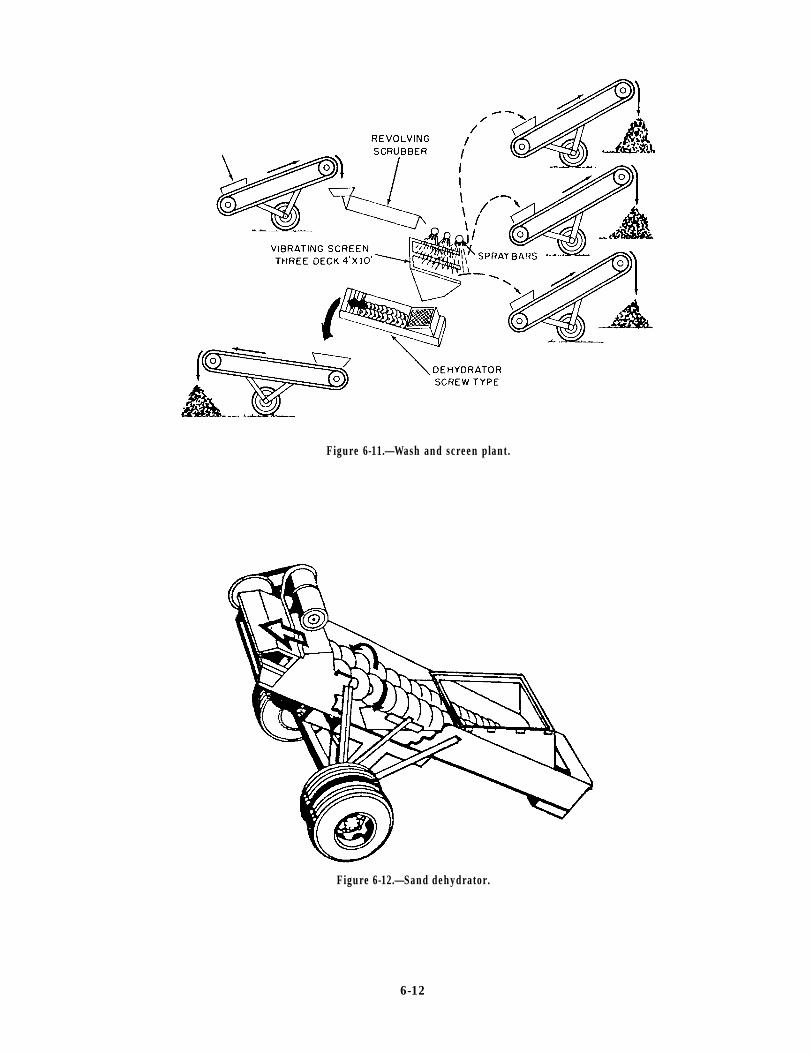
Figure 6-11.—Wash and screen plant.
Figure 6-12.—Sand dehydrator.
6-12

PLANT LAYOUT
Once the plant is in operation, there is seldom timeavailable to stop operations to remodel; therefore, thelayout and erection of the crusher unit should be givenadequate time to ensure an efficient facility is built.
Equipment Configuration
Special attention should be given to creating alogical flow of material from the point where trucksenter the plant with raw material to the point wheretrucks depart from the crusher with crushed aggregateproducts. You should evaluate the physicalenvironmental requirements of each piece ofequipment, such as foundation requirements, waterrequirements, and power requirements, to ensure theyare included during the construction stage.
Drainage
Adequate drainage charnels should be constructedduring the initial earthworking stage of construction andconstantly improved as the plant is built. This issignificant because most of the rock crushing plantshave electrical components inherent to their operation.
Prevailing Winds
Equipment should be oriented in such a manner thatprevailing winds carry the rock dust generated by thecrusher away from the facility. Support equipment, suchas generators and water pumps, and permanentfacilities, such as latrines, offices, and maintenanceshops, should be located out of the path of windscarrying the rock dust.
DO NOT FORGET THE DEPARTMENT OFENVIRONMENT’AL QUALITY (DEQ) REQUIRE-MENTS FOR DUST CONTROL. The DEQ works forthe Environmental Projection Agency (EPA). The EPAhas established standards for controlling the amount ofrock dust that can be admitted into the air.
The COMSECOND/COMTHIRDNCB EquipmentOffices work closely with the DEQ to ensure the plantsin the NCF abide by the rules of the DEQ. Sprinklersystems have been installed on rock crushers in the NCFto control the rock dust produced from crushingoperations to meet the requirements of one rule. As thecrusher supervisor, you are responsible to make surethese systems remain operational.
Organization of Space
The crusher design should include adequate spacearound the equipment. This space is required to provideaccess areas for maintenance personnel to performrepairs, space to move cranes in and out to lift out andreplace or rotate worn jaw plates and roll shells, spacefor the fuel truck to refuel the equipment, and space toremove and replace components of the crusher unit.
Material Handling and Storage
T h e p l a n t should include adequatematerial-handling devices to expedite the flow ofmaterial through the plant and eliminate doublehandling of the material.
A headwall ramp should be constructed to allowhaul units or loaders to back up to or approach the apronfeeder of the primary unit and discharge their loads. Ifa problem with oversized rock is anticipated, you shouldhave a prescreening grizzly built in the quarry or overthe apron feeder to remove the oversized rock.
When possible, store quality product size aggregatein bins, rather than in open stockpiles. This is mostimportant when the aggregate is crushed tospecifications sizes or has been washed. Openstockpiling of aggregate can be contaminated bywindblown sand, fines, and trash.
When bins are not available for aggregate storage,headwalls should be constructed for stockpiles to ensureseparation of different sizes of aggregate beingprocessed. The area separating headwalls should belarge enough to stockpile a large supply of aggregate andhave adequate space on the front side for loadingvehicles without causing congested traffic areas.
Aggregate stockpiles are loaded by loaders orclamshells. These machines are most efficient forloading vehicles with clean aggregate off the top ofstockpiles. The aggregates at the bottom of stockpilesbecome embedded in the ground and tend to becomecontaminated. This layer is lost for use.
Stockpiling
Stockpiling is most efficiently accomplished onhard, flat, clear areas. The location of the stockpilesshould be convenient to the quarry, the crusher, and thehauling unit. When available space is large comparedwith the bulk of material to be stored, trucks may dumppiles as closely as possible to each other.
6-13
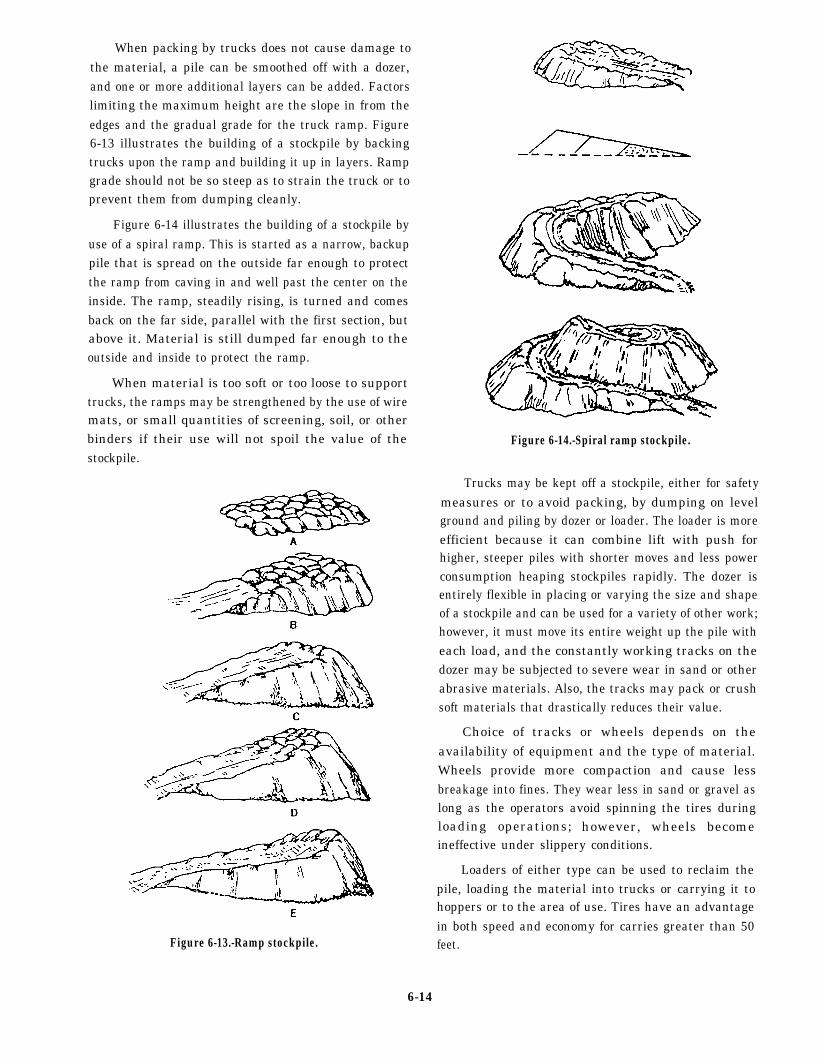
When packing by trucks does not cause damage tothe material, a pile can be smoothed off with a dozer,and one or more additional layers can be added. Factorslimiting the maximum height are the slope in from theedges and the gradual grade for the truck ramp. Figure6-13 illustrates the building of a stockpile by backingtrucks upon the ramp and building it up in layers. Rampgrade should not be so steep as to strain the truck or toprevent them from dumping cleanly.
Figure 6-14 illustrates the building of a stockpile byuse of a spiral ramp. This is started as a narrow, backuppile that is spread on the outside far enough to protectthe ramp from caving in and well past the center on theinside. The ramp, steadily rising, is turned and comesback on the far side, parallel with the first section, butabove it. Material is still dumped far enough to theoutside and inside to protect the ramp.
When material is too soft or too loose to supporttrucks, the ramps may be strengthened by the use of wiremats, or small quantities of screening, soil, or otherbinders if their use will not spoil the value of thestockpile.
Figure 6-13.-Ramp stockpile.
Figure 6-14.-Spiral ramp stockpile.
Trucks may be kept off a stockpile, either for safetymeasures or to avoid packing, by dumping on levelground and piling by dozer or loader. The loader is moreefficient because it can combine lift with push forhigher, steeper piles with shorter moves and less powerconsumption heaping stockpiles rapidly. The dozer isentirely flexible in placing or varying the size and shapeof a stockpile and can be used for a variety of other work;however, it must move its entire weight up the pile witheach load, and the constantly working tracks on thedozer may be subjected to severe wear in sand or otherabrasive materials. Also, the tracks may pack or crushsoft materials that drastically reduces their value.
Choice of tracks or wheels depends on theavailability of equipment and the type of material.Wheels provide more compaction and cause lessbreakage into fines. They wear less in sand or gravel aslong as the operators avoid spinning the tires duringloading operations; however, wheels becomeineffective under slippery conditions.
Loaders of either type can be used to reclaim thepile, loading the material into trucks or carrying it tohoppers or to the area of use. Tires have an advantagein both speed and economy for carries greater than 50feet.
6-14

Road Networks
During the plant erection stage, plans should bemade for the layout of roads. Well-planned roads areneeded to prevent congestion, decrease the time haulunits are in the plant, and for safety. Road networks areneeded for the following:
1. Haul units bringing rock from the quarry
2. Trucks hauling the product aggregate toconstruction sites
3. Service vehicles, such as crew, fuel, andmaintenance vehicles
If possible, plant roads should be one way and bewide enough for the largest haul unit expected. Theyshould be designed to support heavy loads.
Plant roads must be maintained constantly. In dryareas where there is little rainfall, a water truck isrequired to wet down the roads to control the dust. Inwet areas crushed rock should be used on the roads tokeep haul units from sliding off into ditches. Amaximum speed limit should be posted for vehiculartraffic within the crusher area and on the haul roads.
PLANT ERECTION
The importance of proper site preparation andproper stationing of the plant cannot beoveremphasized. Your site for stationing the plantshould be flat, level, and well compacted. Crushing andscreening plants may be operated for short periods oftime from the wheelbase. But it is advantageous onlonger and more deliberate jobs, from a maintenancestandpoint, not to operate the plant until it has beenblocked and leveled with the tires clear of the ground.You should include the following steps in theoperational start-up phase:
Operating instructions. All appropriate technicalmanuals must be reviewed and studied before thebeginning of plant operations.
Training. You should train all personnel assignedto operate and maintain the plant. During this trainingperiod the importance of site preparation, setup,maintenance, and safety should be emphasized. Youshould keep the proper tools, materials, and manuals atthe site. A high rate of aggregate production should notbe expected until personnel become familiar with theequipment.
Tools. The tools used in maintenance and assembl yof the plant are included in the mechanic’s tool kit which
is part of the NCF TOA. Basic issue items that areincorporated with each plant are also available.
Leveling. The plant should be leveled before initialoperation and should be frequently checked while inoperation. Leveling should be done on the frame forlongitudinal leveling. A rigid, straight plank should beused across the unit frame rails for transverse leveling.The leveling should be checked at several pointsthroughout the unit.
Blocking. Blocks should be installed under eachside of the tandem axles and under the dolly axle or thefifth wheel plate to raise the tires or landing gear clearof the ground. Place blocking or cribbing parallel to thelongitudinal center line of the unit.
Hydraulic jacks. Jacks should be on each side ofthe unit opposite each other and under the unit framemembers. Raise and lower the jacks in equal incrementsto prevent bending of the frame.
Screw type of stabilizing jacks. Tighten the screwtype of stabilizing jacks to maximum torque after thecrusher has been blocked and leveled.
retorquing should be continued throughout the
Nuts and bolts. Ensure all bolts are tight bytorquing the nuts, not the bolt heads. Additionally,
operation of the plant. This should be performed atcritical locations and during the initial operation toassure proper seating and prevent parts from looseningand getting out of adjustment. Any adjustmentsrequired, such as movement of trunnion wheels on thetrunnion shaft, should be made during the first hours ofoperation.
Jaw plates and roll shells are held in place bywedges which are secured by keeper bolts. The wedgesmust be driven home with a sledge hammer whileconstantly applying torque with the wrench to achieveproper tightening.
Visual inspection. To prevent damage and eventualbreakage, you should visually inspect the plantconstantly to detect any misadjustment or loss ofadjustment. Visual inspections should be made fromground level, from the platform, and from walkways.All adjustments should be checked with the componentsoperating while empty and rechecked while loaded withaggregate.
75-tph Plant
The 75-ton-per-hour plant is used in any of fourbasic setups, depending upon the raw material available
6-15
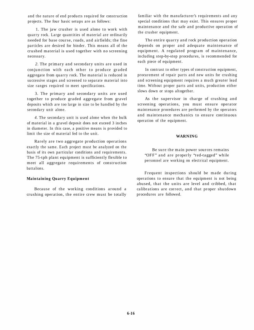
and the nature of end products required for constructionprojects. The four basic setups are as follows:
1. The jaw crusher is used alone to work withquarry rock. Large quantities of material are ordinarilyneeded for base course, roads, and airfields; the fineparticles are desired for binder. This means all of thecrushed material is used together with no screeningnecessary.
2. The primary and secondary units are used inconjunction with each other to produce gradedaggregate from quarry rock. The material is reduced insuccessive stages and screened to separate material intosize ranges required to meet specifications.
3. The primary and secondary units are usedtogether to produce graded aggregate from graveldeposits which are too large in size to be handled by thesecondary unit alone.
4. The secondary unit is used alone when the bulkof material in a gravel deposit does not exceed 3 inchesin diameter. In this case, a positive means is provided tolimit the size of material fed to the unit.
Rarely are two aggregate production operationsexactly the same. Each project must be analyzed on thebasis of its own particular conditions and requirements.The 75-tph plant equipment is sufficiently flexible tomeet all aggregate requirements of constructionbattalions.
Maintaining Quarry Equipment
Because of the working conditions around acrushing operation, the entire crew must be totally
familiar with the manufacturer’s requirements and anyspecial conditions that may exist. This ensures propermaintenance and the safe and productive operation ofthe crusher equipment.
The entire quarry and rock production operationdepends on proper and adequate maintenance ofequipment. A regulated program of maintenance,including step-by-step procedures, is recommended foreach piece of equipment.
In contrast to other types of construction equipment,procurement of repair parts and new units for crushingand screening equipment requires a much greater leadtime. Without proper parts and units, production eitherslows down or stops altogether.
As the supervisor in charge of crushing andscreening operations, you must ensure operatormaintenance procedures are performed by the operatorsand maintenance mechanics to ensure continuousoperation of the equipment.
WARNING
Be sure the main power sources remains“OFF” and are properly “red-tagged” whilepersonnel are working on electrical equipment.
Frequent inspections should be made duringoperations to ensure that the equipment is not beingabused, that the units are level and cribbed, thatcalibrations are correct, and that proper shutdownprocedures are followed.
6-16

CHAPTER 7
CONCRETE BATCH PLANT SUPERVISOR
Concrete is a mixture of cement and water that bindsaggregates, such as sand and gravel or crushed stone,into a rockdikc mass and when properly constructed, itis very rigid and has a long life. This is a result of thechemical reaction between the cement and water calledhydration. The Naval Construction Force (NCF) hasvarious equipment used to provide concrete forconstruction purposes. This equipment ranges from the11S mixer, transit mixer, mobile concrete mixer plant(crete mobile), and the concrete batch plant.
Most concrete production operations are supportedby an experienced Builder (BU). However, EOs mustunderstand the basic principles of concrete mix designand the procedures performed to produce qualityconcrete.
CONCRETE BATCH PLANTSUPERVISOR RESPONSIBILITIES
When assigned as the supervisor of a concrete batchplant in the NCF, you supervise the production andtransport of concrete products used to constructsidewalks, roads, footers, foundations, walls, roofs,runways, rapid runway repairs, and so forth.
PORRLAND CEMENT
Portland cement is usually made of materials,such as limestone or marl and shale or clay. The rawmaterials are crushed, pulverized, and mixed inproper proportions for the correct chemicalcomposition. Then, the raw material is fed into arotary kiln and is calcined (burned) at a temperatureof approximately 2700°F. This process transforms thematerial into a clinker. The clinker is cooled andpulverized so fine that nearly all of the powder canpass through a No. 200 mesh sieve.
Types of Cement
When powdered Portland cement and water arecombined, hydration occurs, The amount of water perunit weight of cement is called the water-cement rationormally given in terms of pounds of water per poundsof cement. Concrete with a low water cement ratio gains
more strength than cement with a higher water cementratio.
There are many types of cement, but only the mostcommon types are listed here:
Type I (normal portland cement) is the mostwidely used cement for pavements, sidewalks,buildings, bridges, masonry units, and soil-cementmixtures. In general, it is used when the concrete willnot be subjected to special sulfate hazards or where theheat generated by the hydration of the cement does notcause an objectionable rise in temperature.
Type II (modified portland cement) has a lowerheat of hydration than Type I. This lower heat gives thiscement an improved resistance to sulfate attack. Type IIcement is used in large structures where cement ofmoderate heat of hydration tends to minimize a rise intemperature. Examples are as follows: large piers, heavyabutments, heavy retaining walls, and when the concreteis placed in warm weather. Type 11 cement is also usedin drainage structures where the sulfate concentrationsare higher than normal.
Type III (high-early-strength portland cement) isused when superior strength is required in a short time.It is used in cold-weather construction to reduce theperiod of protection against low temperatures. Type IIIis also used when forms have to be removedimmediately to allow the concrete to be put in serviceas quickly as possible. Type III cement requires lessprotection time from freezing and attains normal 3-daystrength in 1 day. The volume of heat during hydrationis also accelerated. Normally, this cement is not used inlarge-scale construction operations because it is veryexpensive.
Storage of Cement
Portland cement is a moisture-sensitive materialthat must be protected from damp air or moisture.Cement not protected when in storage sets more slowlybecause hydration has already begun; therefore, it hasless strength than portland cement that is kept dry.
Most types of portland cement are shipped in bulkby rail, truck, or barge. Pneumatic loading andunloading of the transport vehicles is the usual method
7-1

used to handle bulk cement. Bulk cement is measuredin tons (2,000 lb) and smaller quantities are bagged incloth or paper sacks, each containing 94 pounds ofcement. A 94-pound sack of cement is equal to 1 cubicfoot by loose volume.
Cement bags should not be stored on damp floors,but should rest on pallets. The bags should be stackedagainst each other to prevent circulation of air betweenthem, but not stacked against outside walls. If the stacksof cement are to be stored undisturbed for long periods,they should be covered with tarpaulins.
Cement bags that have been stacked in storage forlong periods sometimes acquire a hardness calledWAREHOUSEPACK. This can usually be loosened byrolling the sack around. Cement that has lumps or is notfree flowing should not be used.
AGGREGATE
separately-the fine aggregates on sieves with openings1/4 inch or smaller and the coarse aggregate on sieveswith square openings from about 1/4 inch and larger.The fine sieves are numbered—the larger the number, thesmaller the sieve opening; for instance, the No. 100sieve has 100 openings per inch, and the No. 4 sieve has4 openings per inch.
The grading of both coarse and fine aggregate andthe relative proportions of each in the mix can greatlyaffect the properties of the fresh concrete. Concretemade with coarse sand or not enough sand is hard topump and will be harsh and difficult to trowel. Also,aggregates can segregate or separate from the cementpaste during placement, producing nonuniformconcrete. Air-entraining will help in overcominggrading problems of this kind. Coarse aggregates shouldbe round or subround in shape. This thape allows thecement paste to coat the particles more easily duringmixing.
The aggregates used in concrete must be strong, HANDLING AND STORAGE OFdurable, and chemically inert and generally occupy 60 AGGREGATESto 75 percent of the concrete mix in volumc (70 to 85percent by weight). Natural aggregate deposits are Aggregates containing particles of different sizesexcavated from pits, rivers, lakes, or seabeds. These have a natural tendency to segregate whenever loaded,natural deposits consist of gravel and sand that can be transported, or otherwise disturbed. Aggregates shouldreadily used in concrete after minimal processing. always be handled and stored by a method thatCrushed aggregates are produced by crushing quary minimizes segregation.rock, boulders, cobbles, or large-size gravel. Crushed
Stockpiles should not be built up in cone shapes,aggregates are usually washed and graded before being
formed by dropping successive loads at the same spot.used in concrete. The most commonly used aggregates
This process causes larger aggregate particles toare sand and gravel and when combined with cementproduce a strong, durable mass that is practically
segregate and roll down the sides, leaving the pile with
without voids.a large amount of fine aggregate at the top and a largeamount of coarse aggregate at the bottom. A stockpile
The coarse aggregates used in a mix usually consist should be built up in layers, each made by dumpingof gravel or crushed stone up to 1 1/2 inches in size. successive loads alongside each other.Course aggregates are primarily used as filler. These
If aggregate is dropped in a free fall from aaggregates can pass through a 3-inch sieve and areretained on a No. 4 sieve. In massive structures like
clamshell, loader, or a conveyor, some of the fine
dams, the coarse aggregates may include natural stonesmaterial may be blown aside, causing segregation offines on the lee side of the pile. Clamshells, loaders, and
or rocks, ranging up to 6 inches or more in size.conveyors should be discharged in contact with the
Fine aggregates are those materials that can pass pile.through a No. 4 sieve but are retained on a No. 100 sieve.The fine aggregates and sand in concrete are used to fillthe voids between the large aggregates. Care should betaken to prevent dirt and othcr debris from getting mixedinto the sand. The foreign material affects the bondingquality of the sand.
The gradation of the aggregate is a major factor inthe workability, water requirements, and strength ofconcrete. Fine and coarse aggregates are usually sieved
The bottom of an overhead charging bin shouldalways slope at least 50 degrees towards the centeroutlet. If the slope is less than 50 degrees, segregationwill occur as the material is discharged. When a bin isbeing charged, the material should be dropped from apoint directly over the outlet. Material dropped in at anangle or discharged against the sides of the bin willsegregate. Since a long drop causes both segregation andthe breakage of aggregate particles, the length of a drop
7-2

into a bin should be kept to a minimum by keeping thebin as full as possible at all times.
WATER
The primary function of water used in a concretemix is to start the hardening process of the concretethrough hydration of the cement. A secondary functionis to make the mix workable enough to satisfy therequirements of the job. However, too much water willcause a loss of strength by upsetting the water-cementratio. It will also cause “water gain” on the surface, acondition which leaves a surface layer of weak materialcalled LAITANCE. Also, an excessive amount of waterwill impair the water tightness of the concrete.
Water used in mixing concrete must be clean andfree from oils, alkalis, acids, and organic materials. Mostspecifications recommend the mixing water be fit fordrinking. This is because any water fit for drinking isusually satisfactory for use in mixing concrete.Seawater may be used for unreinforced concrete.
ADDITIVES USED INCONCRETE
There are several additives or admixtures used tochange the composition of concrete or to accelerate orretard its hardening. The three commonly used areair-entraining agents, retarders, and accelerators.Additives are not recommended if the end result can bereached more economically by altering the mixproportions.
Air-entraining portland cement is a specialcement that can be used with good results for a varietyof conditions. It was developed to produce concrete thathas a resistance to freeze-thaw action and scaling causedby chemicals applied for severe frost and ice removal,Air-entraining agents are liquids derived from naturalwood resins, animal fats, vegetable fats, or variouswetting agents, such as alkali salts and water-solublesoaps. Agents are blended with the cement duringmanufacturing or added at the mixing site. If done at thesite, the agent is added to the water used in themix.
Manufactured air-entraining cements are indicatedby the letter A in the type number (Types IA, IIA, IIIA,etc.). Concrete made with this cement contains billionsof extremely small, entirely separated air bubbles percubic foot of concrete. These bubbles provide space forwater to expand due to freezing without damage to theconcrete.
Retarders are used to slow down the rate of settingof a concrete. High temperatures of fresh concrete(85°F - 90°F and higher) are often the cause of anincreased rate of hardening that makes placing andfinishing difficult. One practical way to reduce thetemperature of the concrete is by cooling the mixingwater or the aggregates. Retarders do not decrease theinitial temperature of the concrete. Retarders aresometimes used (o do the following:
1. Offset the accelerating effect of hot weather onthe setting of concrete
2. Delay the initial set of concrete when difficult orunusual conditions of placement occur, such asplacing concrete in large piers and foundations
3. Delay the set for a special finishing process,such as an exposed aggregate surface
Some of the materials used to retard the set of aconcrete mixture are lignin, borax, sugar, tartaric acid,and salt. These materials should be added to the mixingwater.
CAUTION
If 20 percent by volume of regarding agentis added to the mix, the effect is reversed and itthen acts as an accelerator.
Accelerators are used to accelerate the strengthdevelopment of concrete at an early age. Calciumchloride is the material most commonly used inaccelerating admixtures; however, in addition toaccelerating strength gain, calcium chloride causes anincrease in drying shrinkage, potential reinforcementcorrosion, discoloration, and scaling potential. Calciumchloride should be added to the concrete mix in solutionform as part of the mixing water. If added to the concretein dry form, all of the dry particles may not becompletely dissolved during mixing. Undissolvedlumps in the mix can cause pop-outs of dark spots in thehardened concrete. The amount of accelerator usedshould not exceed 2 percent by weight of cement.
COMPUTING CONCRETE VOLUME
To compute the volume of concrete required for aconcrete pad, multiply the length of the pad by its widthtimes its depth to get cubic feet (L x W x D); forexample, a concrete pad is 20 feet in length by 30 feetin width and has a depth of 3 inches. First, convert the3 inches into feet by dividing 3 by 12 to get 0.25 foot.Next, multiply the 20-foot length by the 30-foot width
7-3

to get 600. Finally, multiply the 600 by 0.25 to determinethe volume of concrete required for the pad which, inthis case, is 150 cubic feet.
Concrete is ordered and produced in quantities ofcubic yards. To calculate the number of cubic yardsrequired for the pad, divide the cubic feet of the pad by27. This is required because there is 27 cubic feet in 1cubic yard. Therefore, the concrete pad described in theprevious paragraph, which has a volume of 150 cubicfeet, requires 5.56 cubic yards of concrete: 150 cubicfeet divided by 27 = 5.56 cubic yards.
Concrete projects often present varying degrees ofdifficulty; therefore, extra concrete is required tocompensate for these difficulties. Once the total numberof cubic yards of concrete is computed, add a little extra,normally 10 percent, to compensate for waste. Tocalculate the excess needed, multiply the cubic yards by.10 (10 percent). In the above case, multiply 5.56 cubicyards by .10 to get 0.556 cubic yards. Add the 0.556cubic yards to the 5.56 cubic yards for a total of 6.116or 6.12 cubic yards required for the concrete pad.
BATCHING CONCRETE
Batching is the process of weighing orvolumetricall y measuring and introducing into a mixerthe ingredients for a batch of concrete. To produce auniform quality concrete mix, measure the ingredientsaccurately for each batch. Most concrete specificationsrequire that the batching be performed by weight, rathcrthan by volume, because of inaccuracies in measuringaggregate, especially damp aggregate. Water and liquidair-entraining admixtures can be measured accurate]yby either weight or volume. Batching by using weightprovides greater accuracy and avoids problems createdby bulking of damp sand. Volumetric batching is usedfor concrete mixed in a continuous mixer, and themobile concrete mixer (crete mobile) where weighingfacilities are not at hand.
Specifications generally require that materials bemeasured in individual batches within the followingpercentages of accuracy: cement 1%, aggregate 2%,water 1%, and air-entraining admixtures 3%.
Equipment within the plant should be capable ofmeasuring quantities within these tolerances for thesmallest to the largest batch of concrete produced. Theaccuracy of the batching equipment must be checkedand adjusted when neccessary.
Mixing Concrete
Concrete should be mixed until it is uniform inappearance and all the ingredients are evenlydistributed. Mixers should not be loaded above theirrated capacities and should be operated atapproximately the speeds for which they were designed.If the blades of the mixer become worn or coated withhardened concrete, the mixing action will be lessefficient. Worn blades should be replaced and thehardened concrete removed periodically, preferablyafter each production of concrete.
When a transit mixer (TM) (fig. 7-1) is used formixing concrete, 70 to 100 revolutions of the drum atthe rate of rotation designated by the manufacturer asmixing speed are usually required to produce thespecified uniformity. No more than 100 revolutions atmixing speed should be used. All revolutions after 100should be at a rate of rotation designated by themanufacturer as agitating speed. Agitating speed isusually about 2 to 6 revolutions per minute, and mixingspeed is generally about 6 to 18 revolutions per minute.Mixing for long periods of time at high speeds, about 1or more hours, can result in concrete strength loss,temperature rise, excessive loss of entrained air, andaccelerated slump loss.
Concrete mixed in a transit mixer should bedelivered and discharged within 1 1/2 hours or beforethe drum has revolved 300 times after the introductionof water to cement and aggregates or the cement to theaggregates. Mixers and agitators should always beoperated within the limits of the volume and speed ofrotation designated by the equipment manufacturer.
Overmixing Concrete
Overmixing concrete damages the quality of theconcrete, tends to grind the aggregate into smallerpieces, increases the temperature of the mix, lowers theslump, decreases air entrainment, and decreases thestrength of the concrete. Also, overmixing puts needlesswear on the drum and blades of the transit mixer.
To select the best mixing speed for a load ofconcrete, estimate the travel time to the project (inminutes) and divide this into the minimum desirednumber of revolutions at mixing speed-70. The resultswill be the best drum speed; for instance, if the haul is10 minutes, 70 divided by 10 equals 7. With this drumspeed, the load will arrive on the jobsite with exactly 70turns at mixing speed, with no overmixing of theconcrete mix and no unnecessary wear on the
7-4
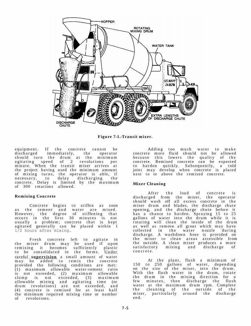
Figure 7-1.-Transit mixer.
equipment. If the concrete cannot bedischarged immediately, the operatorshould turn the drum at the minimumagitating speed of 2 revolutions perminute. When the transit mixer arrives atthe project having used the minimum amountof mixing turns, the operator is able, ifnecessary, to delay discharging theconcrete. Delay is limited by the maximumof 300 rotations allowed.
Remixing Concrete
Concrete begins to stiffen as soonas the cement and water are mixed.However, the degree of stiffening thatoccurs in the first 30 minutes is notusually a problem; concrete that is keptagitated generally can be placed within 11/2 hours after mixing.
Fresh concrete left to agitate inthe mixer drum may be used if uponremixing it becomes sufficiently plasticto be consolidated in the forms. Undercareful supervision a small amount of watermay be added to remix the concreteprovided the following conditions are met:(1) maximum allowable water-cement ratiois not exceeded, (2) maximum allowableslump is not exceeded, (3) maximumallowable mixing and agitating time (ordrum revolutions) are not exceeded, and(4) concrete is remixed for at least halfthe minimum required mixing time or numberof revolutions.
Adding too much water to makeconcrete more fluid should not be allowedbecause this lowers the quality of theconcrete. Remixed concrete can be expectedto harden quickly. Subsequently, a coldjoint may develop when concrete is placednext to or above the remixed concrete.
Mixer Cleaning
After the load of concrete isdischarged from the mixer, the operatorshould wash off all excess concrete in themixer drum and blades, the discharge chuteopening, and the discharge chute before ithas a chance to harden. Spraying 15 to 25gallons of water into the drum while it isrotating will clean the inside of the drumas well as remove all grout which may havecollected in the water nozzle duringdischarge. A washdown hose is provided onthe mixer to clean areas accessible fromthe outside. A clean mixer produces a moresatisfactory mixing and discharge ofconcrete.
At the plant, flush a minimum of150 to 250 gallons of water, dependingon the size of the mixer, into the drum.With the flush water in the drum, rotatethe drum in the mixing direction for afew minutes, then discharge the flushwater at the maximum drum rpm. Completethe cleaning of the outside of themixer, particularly around the dischargeend.
7-5

Figure 7-2.
7-6

MOBILE CONCRETE MIXERPLANT
The trailer-mounted mobile concrete mixer plant(fig. 7-2) carries cement, sand, and coarse aggregates individed bins mounted on the unit. The cement is carriedin a separate bin located across the rear of the unit, andthe sand and aggregate are carried on each side of theunit. Water is carried in a single tank mounted in frontof the aggregate bins and is pumped to the mix auger.Sand and aggregates are accurately proportioned byweight or volume and simultaniously dropped with amixture of cement from the material feed system intothe charging end of the mix auger/conveyor at the rearof the unit. At this point, a predetermined amount ofwater enters the mix auger. The action of this combinedauger and paddle homogenizer mixes the ingredientsand water rapidly, thoroughly, and continuously toproduce a continuous flow of uniformed qualityconcrete. The material mixing action is a continuousprocess that can proceed until the aggregate bins areempty. On the other hand, mixing and delivery may bestopped at any time and then started again at the will ofthe operator. This permits production to be balanced tothe demands of the placing and finishing crews and otherjob requirements.
Operators assigned to the “crete mobile” mustthoroughly read and understand the technical manualbefore operating the plant.
The following are the mobile concrete mixer plantcautions and warnings:
Follow all preventivc maintenance procedures.
Do not allow any foreign matter in the cementbin.
Do not allow paricles larger than 1 1/2 inch inthe aggregate bin.
Do not allow the waterlines and flowmeters tofreeze with water in them.
Do not run the water pump dry.
Do not continue to operate the machine if thehydraulic oil temperature exceeds 190°F.
Wash out the auger within 20 minutes of the lastuse.
l
l
l
l
l
l
Never attempt to repair the machine while inoperation (always turn the power sourceoff).
Keep your entire body clear from all movingparts.
Never attempt to walk on top of the aggregate binto cross from the cement bin to the water tank(use the ladder).
Never walk or stand under the auger.
Never climb inside the aggregate bin (use a smallpole to dislodge any aggregate that hasbridged).
Never enter the cement bin while in operation(there are moving parts inside the bin). -
SLUMP TEST
The slump test is used to measure the consistencyof a concrete mix. The test is normally performed by anEngineering Aid (EA) and is made by using a slumpcone. The cone is 12 inches high with an8-inch-diameter base and a 4-inch-diameter top (fig.7-3).
A bucket is filled with a sample of the concrete fromthe discharge chute from the mixer. From this sample,the cone is filled in three layers. Each layer shouldcontain approximately one third of the volume of thecone. Each layer is rodded in the cone with 25 strokesfrom a 5/8-inch-diameter tamping rod 24 inches long.The strokes should be distributed uniformly over thecross section of the cone and should penetrate into theunderlying layer. The bottom layer should be rodded
Never attempt to operate the unit while in motion. Figure 7-3.-Measurement of slumps.
7-7

throughout the depth. The strokes will eliminate anyvoids when the concrete is placed in the cone.
If the cone is overfilled, the excess concrete is madeflush with the top of the cone with a straightedge. Thecone is raised from the concrete by raising the conecarefully in a vertical direction. The slump is determinedby measuring the difference between the height of thecone and the height of the concrete specimen (fig. 7-3).The slump is recorded in inches on the quality controlreport.
After the slump measurement is completed, the sideof the mix is tapped gently with the tamping rod. Thebehavior of the concrete under this test is a valuableindication of the cohesiveness, workability, andplacability of the concrete mix. If the mix iswell-proportioned, tapping will only cause it to slumplower and retain its original identity, and a poor mix willcrumble, segregate, and fall apart. Normally, the EAsperform three slump tests per truck load of concrete.Another test performed by the EAs on a concrete mix isa concrete strength test. This test is performed to controlthe quality of concrete manufactured in the field, toevaluate the performance of available materials used ina concrete mix, and to establish mix proportions thatgive concrete the required strength.
PLANT SAFETY
1.
2.
3.
All personnel working in the batch plant areashould wear hard hats at all times.
When hoppers are being charged with aclamshell or loader, personnel should stay awayfrom the area of falling aggregate.
Housekeeping of the charging area is important.Keep the area clean and free of spoiled materialand overflow.
4.
5.
6.
Respirators must be worn by all personnel whenhandling bag or bulk cement.
Particular attention should be given to any rashor other irregularities of the skin as it mightindicate “cement poisoning.”
Vapor type of goggles should be worn bypersonnel in batch plant operations.
TRANSIT MIXER SAFETY
The use of transit mixers on construction projectsimpose traffic problems that must be considered.Caution must be used during backing of the transitmixer. Backing should be controlled by a signalman,positioned so the operator can clearly observe thedirections given. Extrement caution must be used whentraveling on a construction site. The stability of themixer is greatly reduced with the extra weight of theconcrete. Also, the weight of the mixer can crush newlyplaced underground utilities, sink in the mud, cracksidewalks, and so forth. In such cases, a slow speed isrecommended.
Some additional safety precautions that must beenforced are as follows:
1.
2.
3.
4.
Reduce speed before making a turn or applyingthe truck brakes.
Secure the discharge chute properly, using thelock provided.
Check to make certain other personnel are in theclear before starting the mixer charging ordischarging.
Make sure the mixer is stopped before makingany adjustments.
7-8

CHAPTER 8
ASPHALT PLANT SUPERVISORThe Naval Construction Force
(NCF) uses various makes and modelsof asphalt plants in both theAt lant ic and Pac i f i c F leetdeployment sites. As an asphaltplant supervisor, you are a keymember and share the responsibilityfor producing a quality mix. Youmust be aware of all operationalfunctions of the plant and bring tothe attention of the Alfa companyoperations chief any detectedproblems or potential problems.Additionally, you must be aware of allfederal, state, and local regulationsand ordinances relating to theoperation of the plant, such as airand water pollution restrictions, antinoise requirements, restricted hoursof operation, and so forth. Befored e p l o y i n g , c o n t a c t t h eCOMSECOND/COMTHIRDNCB equipmentoffices for Environmental Protection Agency(EPA) directives,and operator’s manualsthat relate to the asphalt plant atyour prospective deployment site.
ASPHALT PLANT SUPERVISORRESPONSIBILITIES
This chapter presents the basicinformation concerning the operations ofasphalt plants and the production and usesof bituminous materials. The Seabees needwell-qualified personnel to operate andmaintain asphalt plants. To ensurepersonnel are qualified, you mustemphasize on-the-job training programs.Also, personnel must gain a thoroughunderstanding of the manufacturers’operator and maintenance manuals.
An asphalt plant is an assembly ofmechanical, computerized, electronicequipment where aggregates are blended,heated, dried, and mixed with asphalt toproduce a hot-asphalt mix that meetsspecified requirements. An asphalt plantcan be small, large, stationary, orportable. Whatever the size orconfiguration, every plant can becategorized as either a batch asphaltplant (fig. 8-1), a continuous-flow
Figure 8-1.—Batch asphalt plant.
8-1
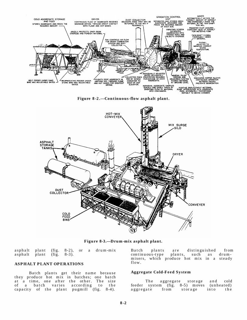
Figure 8-2.—Continuous-flow asphalt plant.
Figure 8-3.—Drum-mix asphalt plant.
asphalt plant (fig. 8-2), or a drum-mixasphalt plant (fig. 8-3).
ASPHALT PLANT OPERATIONS
Batch plants get their name becausethey produce hot mix in batches; one batchat a time, one after the other. The sizeof a batch varies according to thecapacity of the plant pugmill (fig. 8-4).
Batch plants are distinguished fromcontinuous-type plants, such as drum-mixers, which produce hot mix in a steadyflow.
Aggregate Cold-Feed System
The aggregate storage and coldfeeder system (fig. 8-5) moves (unheated)aggregate from storage into the
8-2

Figure 8-4.-Pugmill
plant. The feeder may be charged by a clamshell orfront-end loader. Aggregate feeder units should havecontrols that can beset and secured to produce a uniformflow of aggregate to the cold elevator.
For a uniform OUTPUT from the asphalt plant,INPUT must be accurately measured. The importanceof feeding the exact amounts of each size aggregate intothe dryer at the correct rate of flow cannot beoveremphasized.
The following conditions ensure a uniform flow ofaggregate sizes:
l Correct sizes of aggregate in stockpiles.
l No intermixing of stockpiles.
. Accurately calibrated, set, and secured feedergates.
. Gates kept free of obstruction.
l No excessive arching in the fine aggregates.Arching can be minimized by using rectangular (ratherthan square) openings above the feeders or placing
Figure 8-5.-Aggregate storage and cold-feed system.
8-3

Figure 8-6.-Calibration chart, gradationfeeder gates.
vibrators on the outside of the fineaggregate bins, or both. Vibrators shouldbe wired to cut off automatically when thefeeder stops. This eliminates excessivepacking in the bin.
The following conditions underscorethe need for proper cold feeding:
• Wide variations in the moisturecontent or in the quantity of a specificaggregate at the cold feed may cause aconsiderable change in the temperature ofthe aggregate leaving the dryer.
• A sudden increase in the coldfeed can overload the screens, creating acarry-over of the fine aggregate into thecoarse aggregate hot bins.
• Erratic feeding may cause somebins to overfill while starving others.This can result in the following problems:
1. Layers of variable grading in thehot bin gradation unit storage,especially in the fine bin,resulting in alternating rich andlean batches
2. An overloaded dust collection system
3. A reduced dryer draft
The cold aggregate feeder gatesshould be calibrated. Most manufacturersfurnish approximate calibrations for thegate openings of their equipment. Whenthese are available, they are helpful inmaking the initial gate setting. But theonly accurate way to set gates is bymaking a calibration chart for each gate,using the aggregate to be used in the mix.
The gate opening (in inches orsquare inches) is plotted on the chart asthe horizontal coordinate, and the poundsof material per revolution of the feedingmechanism (or pounds per minute) is thevertical coordinate. When the calibrationchart is being prepared, the gate is set,usually at 25 percent or less of the totalopening, and the feeder is started. Whenthe feeder is running normally, thematerial is measured into a tare containerand weighed at known time intervals (ornumber of revolutions). This gives onepoint on the calibration chart. Theoperation is repeated for three or moregate openings and the points connected onthe chart (fig. 8-6). After the gates havebeen calibrated and locked, minoradjustments may be necessary to assureuniform production.
When the gates discharge on to thebelt conveyer, their output may be checkedby closing all of the gates except one,which is set at one of the calibrationpoints. When the gates cannot be closedcompletely, it may be necessary to stopthe feeder or disconnect it if it ismechanically driven.
The plant is started and brought tonormal operating speed. Then the plant isstopped and the material from a measuredsection of the belt is removed andweighed, using care to remove all fines.
The weight of the material, dividedby the length (in feet) of the beltsection, multiplied by the belt speed (infeet per minute), will give the amount ofmaterial delivered per minute from thegate opening. The material from other gateopenings is determined in the same mannerand the gate calibration chart plotted asdescribed above.
When variable speed drives are used tocontrol belt feeders, calibration issimplified. The gate opening can beestimated, and the speed of the belt can beincreased or decreased to deliver therequired percentage and tonnage of aggregate.
In calculating the output of a gatefor a given opening, deduct the weight ofthe surface moisture on the aggregatebeing weighed. This is very important
8-4

Figure 8-7.-Dryer.
when calibrating gates through which fine aggregatesare flowing.
For uniform flow, gates that feed coarse aggregateshould not be set at a height less than 2 1/2 to 3 timesthe largest aggregate size; for example, if a gate isfeeding aggregate that has a maximum size of 1 inch,the gate should not be set at less than 2 1/2 or 3 inches.Sometimes it may be necessary to restrict the openingwidth to provide the necessary opening height.
Before you set the cold-feed gates, the productionvolume of the plant in normal operation must bedetermined. this can be estimated from the plant size(dryer, screening, and mixing capacities) and mixingcycle time. Then, using the gate calibration charts, eachgate is set to deliver its share of the desired volume ofaggregate.
Grading of the individual cold aggregate isdetermined by sieve analysis. The percentage of eachsize of aggregate to be used is calculated by trial anderror.
The proportions required on the basis of thesepercentages will determine the gate settings. Thesesettings should be checked by the same method used incalibrating the gate originally.
The setting should be considered tentative becausethe cold aggregate may vary in grading and moisture
with the weather and other conditions that will affect itsbulking and flow.
The hot bins should be watched carefully and thecold aggregate feeders regulated to see that they do notrun out of material or overflow.
Dryer
From the aggregate cold-feed system, aggregatesare delivered to the dryer. The dryer (fig. 8-7) is arevolving cylinder in which the aggregate is dried andheated by an oil or gas burner. The cylinders used rangefrom 3 to 10 feet in diameter and from 15 to 40 feet inlength. A cylinder is usually equipped with longitudinalcups or channels (called lifting flights) that lift theaggregate and drop it in veils through the burner flameand hot gases. The slope of the cylinder, its speed,diameter, length, and the arrangement and number offlights control the length of time required for theaggregate to pass through the dryer.
The dryer performs two functions: (1) it removesmoisture from the aggregate and (2) it heats theaggregate to mixing temperature.
The dryer includes an oil or gas burner with a blowerfan to provide the primary air for combustion of the fueland an exhaust fan to create a draft through the dryer.For efficient dryer operation, the air that is combinedwith the fuel for combustion must be in balance with the
8-5
amount of fuel oil being fed into the burner. The exhaustfan creates the draft of air that carries the heat throughthe dryer and removes the moisture. Imbalance amongthese three elements causes serious problems. With fueloil, lack of sufficient air or excess flow of fuel oil canlead to incomplete combustion of fuel. The unburnedfuel leaves an oily coating on the aggregate particles–acoating that can adversely affect the finished mixture.
Lack of balance between the blower air and draft airvelocities can create hack pressure within the dryerdrum, causing puff back at the burner end. Puff backindicates that the draft is not sufficient to accommodatethe air pressure being introduced by the burner blower.The solution is to increase the draft or to reduce thepressure of the blower air.
Dryer burners using natural gas or liquid petroleumgas rarely develop combustion problems; however, animbalance between gas pressure, combustion air, anddraft can occur. Make sure the gas burner you use is thecorrectly type for the pressure of the gas available.
The temperature of the aggregate, not the asphalt,controls the temperature of the mix. Overheating theaggregate can harden the asphalt during mixing.Underheating the aggregate is difficult to coat withasphalt and the resulting mix is difficult to place;therefore, a pyrometer, which is a reliable and accuratetemperature-measuring device, should be installed inthe dryer discharge in full view of your burner operator.
The pyrometers are sensitive instruments, designedto measure the very small electrical current induced bythe heat of the aggregate passing over the sensingelement. The pyrometer must be completely shieldedfrom the heat and plant vibrations. The head of thedevice is usually located several feet away from thedryer and is connected to its sensing elements by wires.Any change in the connecting wire length, size, splice,or coupling will affect the calibration of the device andit must be recalibrated.
Two types of pyrometers are used. They are asfollows: (1) the indicating pyrometer, which is usuallylocated at the discharge chute of the dryer, and (2) therecording pyrometer. The recording head of thisinstrument is usually located in the plant control room.
The major difference between the indicatingpyrometer and the recording pyrometer is that theindicating pyrometer gives a dial or digital reading, andthe recording pyrometer records aggregate temperatureson paper in graph form providing a permanent record.Both types of pyrometers are quite similar in operation.Both pyrometers have a sensing element; that is, a
shielded thermocouple that protrudes into the mainhot-aggregate stream in the discharge chute of the dryer.
Pyrometers should be cleaned periodically. Dustaccumulating on them may cause a time lag intemperature measurement.They should also be checkedfrequently for accuracy. A simple way to do this is to putthe sensing element of the pyrometer, together with anaccurate thermometer, in an oil or asphalt bath. Beingcautious of the flash point for the bath, slowly heat theoil or asphalt and compare readings from the pyrometerand thermometer. These readings should be taken attemperatures below, through, and above the expectedoperating temperature range.
Another means to check the accuracy of atemperature-indicating device is to take two shovelloads of hot aggregate from the dryer discharge chuteand dump them in a pile on top of each other. The topshovel load of hot aggregate keeps the bottom shovelload of aggregate hot while the temperature is taken.Inserting the entire stem of an armored thermometer intothe hot aggregate pile will give a temperature readingthat can be compared to the reading on the pyrometer.Several thermometer readings may be necessary to getaccurate temperature data.
A moisture check of the hot aggregate can beperformed at the same time a temperature indicatorcheck is performed. From the two shovel loads ofaggregate, observe the aggregate for escaping steam ordamp spots. These are signs of incomplete drying orporous aggregate releasing internal moisture which mayor may not be a problem, Another procedure used tocheck the moisture content is to take adry, clean mirror,shiny spatula, or other reflective item and pass it overthe aggregate slowly and at a steady height. Observe theamount of moisture that condenses on the reflectivesurface. With experience, you will be able to detectexcessive moisture consistently. These quick-moisturechecks are useful in determining whether a more preciselaboratory moisture test should be preformed.
Dust Collector
Manufacturers have designed asphalt plants to haveequipment that restrict the escape of pollutants from theplant. Even so, during the operation of an asphalt plant,some gaseous and particulate pollutants may escape intothe air. These pollutants must be controlled and limitedto meet established clean air regulations. As thesupervisor, you must be fully aware and familiar withthe local laws concerning air pollution.
8-6

Figure 8-8.–Dust collector.
A major air pollution concern at an asphalt plantcenters around the combustion unit. Dirty, cloggedburners and improper air-fuel mixtures result inexcessive smoke and other undesirable combustionproducts; therefore, close attention to the cleanlinessand adjustment of the burners and accessory equipmentis very important.
Another source of air pollution is aggregate dust.The greatest dust emissions from the plant come fromthe rotary dryer. Dust collectors are installed at thislocation to reduce dust emissions to a level that meetsanti-air-pollution requirements.
Most dust collectors (fig. 8-8) are centrifugal(cyclone) units, either horizontal or vertical with single
or multiple shells. Dust particles enter the top of the dustcollector in the current of draft air from the dryer, drawnby the fan(s) that pull(s) the flame and the hot gasesthrough the dryer. In the collector, the dust-laden air isforced into a whirling motion.
Heavier dust particles in the exhaust gas stream areseparated by centrifugal force against the collector shelland are carried to the lower outlet. If the collector worksefficiently, the finer dust that remains in suspension iscarried out the exhaust stack with the air. The finescollected at the bottom of the cyclone are normallypicked up by a dust-return auger and returned to theplant or wasted.
When required by specifications, a baghouse or wetwash system is added to the dust-collecting system.Several types of wet systems are used. They usuallyconsist of a short tower, with or without baffles, ormultiple horizontal tubes with spirals. The washer swirlsthe high-velocity exhaust coming from the dust collectorthrough a fog and a fine spray to wash the gas. Thedampened fines are thrown to the sides by centrifugalforce. The material washes down the sides anddischarges, with the water, out the bottom of the washer.The wastewater containing the dust must be properlyhandled to prevent it from becoming another source ofpollution. Use of a wet wash system requires a largesource of water. Also, the output of the fan in the dustcollector must be increased by 10 to 20 percent becauseof pressure loss in the tower.
The baghouse is a large metal housing, containinghundreds of synthetic, heat-resistant fabric bags. Thebags are usually silicone-treated to increase their abilityto collect and retain very fine particles of dust. Thefunction of the baghouse is similar to the function of avacuum cleaner. A large vacuum fan creates a suctionwithin the housing that draws in dirty air and filters itthrough the fabric of the bags. A typical unit may containas many as 800 bags to handle the huge volume ofexhaust gases from the aggregate dryer. Eventually, theyaccumulate into what is called a “dust cake” that mustbe removed before it reduces or stops the flow of dirtyair through the filter. Several methods for cleaning thebags in the baghouse are used; however, the mostcommonly used methods are as follows: flex the bags,back flush the bags with clean air, or flex and back flushthe bags. The Jet-Pulse system is another method whichis similar to the back flush in that it produces a pulse ofpositive pressure within the bag to dislodge the “dustcake.” Dust removed from the bags drops into an augerat the bottom of the baghouse and is normally
8-7

Figure 8-9.-Gradation control unit.
transferred to a storage silo. This material is often usedin the hot mix.
When the material removed from the dust collectorcan be recombined satisfactorily with the aggregates inthe mix, some or all of it may be returned to the plant.The amount returned depends upon the combinedgrading of the finished mix. When the collected dust isunsatisfactory or is prohibited by the mix specifications,it is removed from the bottom of the collector andwasted.
Hot Screens
After the aggregates have been heated and dried,they are carried by a hot elevator to the gradation unit,In the gradation unit, the hot aggregate passes over a
Figure 8-10.-Screen wear.
series of screens. The function of the screens is toseparate the hot aggregate into the specified sizesaccurately and deposit those sizes in hot bins.
The gradation control unit (fig. 8-9) or screeningunit includes a set of several different-sized vibratingscreens. The top screen is a scalping screen that rejectsand carries off oversized aggregates. This is followed byone or two intermediate-sized screens, decreasing insize from the top to bottom. The very bottom screen isnormally a sand screen. The effective screening areamust be large enough to handle the maximum amountof feed delivered to separate the hot aggregates properly;therefore, the capacity of the screens should be checkedagainst the capacity of the dryer and the capacity of thepugmill .
When too much material is fed to the screens or thescreen openings are plugged, many particles that shouldpass through ride over the screen and drop into a bindesignated for larger sized aggregate. When screens areworn (fig. 8-10) or torn, resulting in enlarged openingsand holes, oversized material will go into bins intendedfor smaller sized aggregate. Fine aggregate misdirectedinto bins intended for larger aggregate is know as“carry-over.”
Carry-over can cause a lack of uniformity in theaggregate gradation and in the mixture. Additionally,excessive carry-over adds to the amount of fineaggregate in the total mix, thus increasing the surfacearea to be coated with asphalt. Excessive carry-over, orits fluctuations, can be detected by a sieve analyses madefrom the contents of the individual hot bins and must becorrected immediately. Corrective measures include thecleaning of screens, the regulation of the quantity ofmaterial coming from the cold feed, or a combination ofboth. Some carry-over is permitted in normal screening;
8-8

however, the permissible amount in each bin is usuallyspecified.
Daily visual inspection of the screens for cleanlinessis recommended, preferably before the start ofoperation. When conditions warrant, the screens shouldbe cleaned.
NOTE: Always make sure the bolts securing thescreens are tight.
Hot Bins
Hot bins are used to store the heated and screenedaggregates temporarily in the various sizes required.Each bin is an individual compartment or a segment ofa large compartment divided by partitions. A properlysized hot-bin installation should be large enough toprevent running out of material when the mixer isoperating at full capacity. Bin partitions should be tight,free from holes, and of sufficient height to preventintermingling of the different size aggregates.
Hot bins usually have indicators that tell when theaggregates fall below a certain level. These indicatorsmay be either electronic or mechanical. Each hot binshould be equipped with an overflow pipe to preventexcess amounts of aggregate from backing up into theother bins. The overfill pipes should be set up to stopoverfilling of the bins. When a bin overfills, the screenabove the bin rides on the aggregate, resulting in heavycarry-over and possible damage to the screen. Overflowvents should be checked frequently to ensure they arefree flowing.
Sometimes, very fine aggregate particles build upin the bin corners. When this buildup of aggregatecollapses, it can result in an excessive amount of finesin the mix. This rush of fine materials normally occurswhen the aggregate in the bin is drawn down too low.This condition can be controlled by having fillet plateswelded in the bin corners to eliminate the 90-degreeangles and by maintaining the proper aggregate level inthe bin.
Other potential obstacles to obtaining a good mixincludes a shortage of aggregate in one bin or excess inanother bin, worn gates (at the bottom of the bins) allowleakage of aggregate, and sweating of the bin walls.These obstacles must be overcome. Bin shortages orexcesses can be corrected by adjusting the cold feed.Sweating occurs when moisture vapor in the aggregateand in the air condenses on the bin walls. his usuallyhappens only at the beginning of the day’s operation orwhen the coarse aggregate is not thoroughly dried.
Figure 8-11.-Segration of material in the bot bins.
Sweating may accumulate dust that, when releasedsuddenly, will add unwanted fines in the mix.
Hot-Bin Sampling
Most modern hot-mix asphalt plants are equippedwith devices for sampling hot aggregate from the bins.These devices vary in design but usually serve to divertthe flow of aggregate from the feeders, or gates, underthe bins into sample containers. On continuous-flowplants, the best place to obtain a sample is from thefeeder gates as the material is deposited onto the elevatorleading to the pugmill. Sampling facilities must beconstructed and located so that the samples obtained willbe representative of the material in the bins.
From the flow of aggregate over the screens, thefiner aggregates fall to the near side of the bins andcoarser aggregates fall to the far side (fig. 8-11). Whenthe aggregate is drawn from a bin by opening a gate atthe bottom, the flow of aggregate consistspredominantly of fine aggregate at one edge and coarseaggregate at the other; therefore, the position of thesampling device in the flow of aggregate determineswhether the sample will be composed of the fine portion,the coarse portion, or will be an accurate representationof all the aggregate in the bin. This condition is criticalin the bin that contains the fine aggregate since theasphalt required in the mix is influenced heavily by theaggregate from this bin.
Stratification (vertical layering) of sizes in the finebin may be caused by variation of grading in thestockpiles or by erratic feeding of the cold aggregate.When this form of segregation exists, representative
8-9
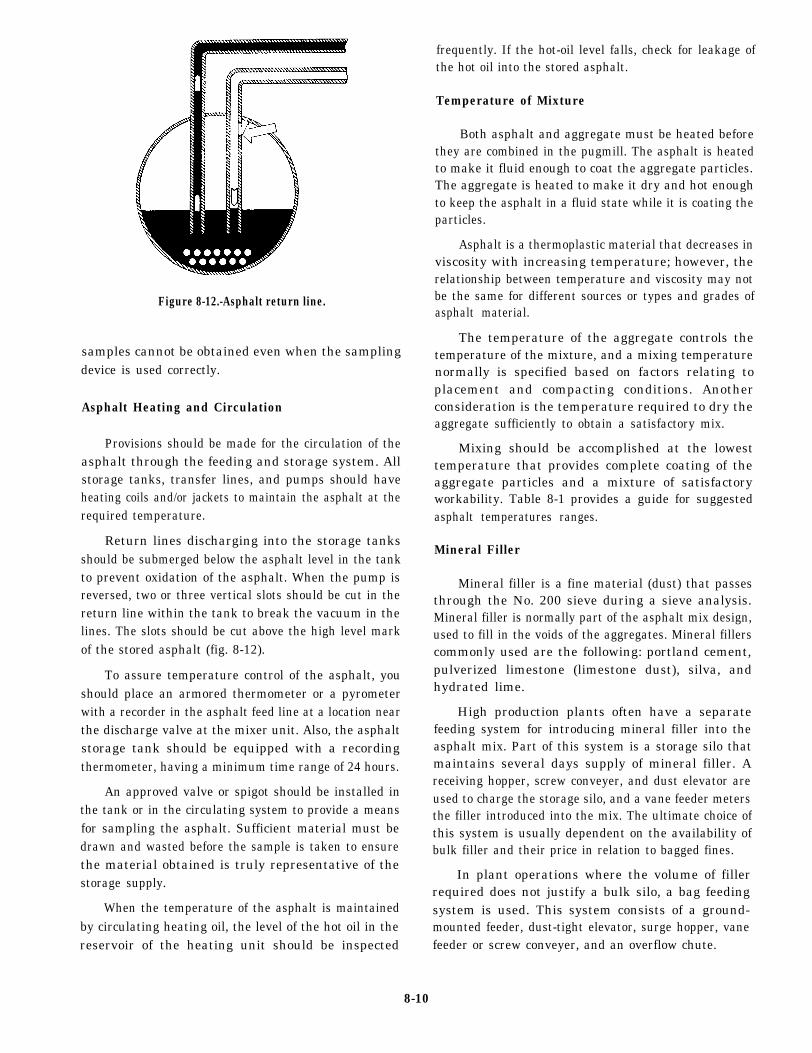
Figure 8-12.-Asphalt return line.
samples cannot be obtained even when the samplingdevice is used correctly.
Asphalt Heating and Circulation
Provisions should be made for the circulation of theasphalt through the feeding and storage system. Allstorage tanks, transfer lines, and pumps should haveheating coils and/or jackets to maintain the asphalt at therequired temperature.
Return lines discharging into the storage tanksshould be submerged below the asphalt level in the tankto prevent oxidation of the asphalt. When the pump isreversed, two or three vertical slots should be cut in thereturn line within the tank to break the vacuum in thelines. The slots should be cut above the high level markof the stored asphalt (fig. 8-12).
To assure temperature control of the asphalt, youshould place an armored thermometer or a pyrometerwith a recorder in the asphalt feed line at a location nearthe discharge valve at the mixer unit. Also, the asphaltstorage tank should be equipped with a recordingthermometer, having a minimum time range of 24 hours.
An approved valve or spigot should be installed inthe tank or in the circulating system to provide a meansfor sampling the asphalt. Sufficient material must bedrawn and wasted before the sample is taken to ensurethe material obtained is truly representative of thestorage supply.
When the temperature of the asphalt is maintainedby circulating heating oil, the level of the hot oil in thereservoir of the heating unit should be inspected
frequently. If the hot-oil level falls, check for leakage ofthe hot oil into the stored asphalt.
Temperature of Mixture
Both asphalt and aggregate must be heated beforethey are combined in the pugmill. The asphalt is heatedto make it fluid enough to coat the aggregate particles.The aggregate is heated to make it dry and hot enoughto keep the asphalt in a fluid state while it is coating theparticles.
Asphalt is a thermoplastic material that decreases inviscosity with increasing temperature; however, therelationship between temperature and viscosity may notbe the same for different sources or types and grades ofasphalt material.
The temperature of the aggregate controls thetemperature of the mixture, and a mixing temperaturenormally is specified based on factors relating toplacement and compacting conditions. Anotherconsideration is the temperature required to dry theaggregate sufficiently to obtain a satisfactory mix.
Mixing should be accomplished at the lowesttemperature that provides complete coating of theaggregate particles and a mixture of satisfactoryworkability. Table 8-1 provides a guide for suggestedasphalt temperatures ranges.
Mineral Filler
Mineral filler is a fine material (dust) that passesthrough the No. 200 sieve during a sieve analysis.Mineral filler is normally part of the asphalt mix design,used to fill in the voids of the aggregates. Mineral fillerscommonly used are the following: portland cement,pulverized limestone (limestone dust), silva, andhydrated lime.
High production plants often have a separatefeeding system for introducing mineral filler into theasphalt mix. Part of this system is a storage silo thatmaintains several days supply of mineral filler. Areceiving hopper, screw conveyer, and dust elevator areused to charge the storage silo, and a vane feeder metersthe filler introduced into the mix. The ultimate choice ofthis system is usually dependent on the availability ofbulk filler and their price in relation to bagged fines.
In plant operations where the volume of fillerrequired does not justify a bulk silo, a bag feedingsystem is used. This system consists of a ground-mounted feeder, dust-tight elevator, surge hopper, vanefeeder or screw conveyer, and an overflow chute.
8-10

Table 8-1.-Suggested Asphalt Temperature Ranges
8-11

Figure 8-13.—Batch asphalt plant hatching unit aggregate weigh-hopper.
Bulk or bag filler systems areequally adaptable for continuous-flowasphalt plants. Final metering of thefiller to the mix is accomplished througha variable speed vane, a screw feeder, ora belt feeder, depending on the materialto be handled and the capacity required.In each case, the mineral filler feed isinterlocked with the aggregate and asphaltfeed to ensure constant accuracy.
When an excess of filler isencountered in the raw aggregate feed, abypass system can be used to receive thefines collected by the dust collector. The
required amount of fines is then fed backto the mix, and any surplus amounts arediverted to a storage bin for disposal orother use.
BATCH ASPHALT PLANT
The batch asphalt plant is shown infigure 8-1. The cold aggregate storage andfeed system, dryer, and dust collector areboth similar in operations for both thebatch and continuous-flow type of asphaltplant. A distinguishing feature of thebatch plant is the batching unit shown infigure 8-13. Here the dried hot aggregate
8-12

Figure 8-14.-Typical batch plant cumulative scale settings and cycle.
is screened into different sizes and stored by size inseparate bins.
From the hot bins the aggregates are deposited intoa weigh-hopper. Coarse aggregates are usually the firstto be deposited into the weigh-hopper, theintermediate-size aggregates next, and the fineaggregates last. This sequence is designed to place thefines of the aggregates at the top of the aggregatesdeposited in the weigh-hopper where they cannot leakout through the gate at the bottom of the weigh-hopper,This system also allows the most efficient utilization of
the available volume in the weigh-hopper. Theweigh-hopper is suspended from scale beams and thescales indicate the weight of the full amount ofaggregate entering the hopper.
When each size of aggregate is deposited into theweigh-hopper, the weights to be drawn from the hot binsare marked on the scale dial. Because the scales indicatethe weights cumulatively, the dial must be markedaccordingly. Figure 8-14 shows how the cumulativescale settings are used to control the proportion ofaggregates drawn from each bin.
8-13

Asphalt Introduction
From the weigh-hopper, the aggregates aredeposited into the plant pugmill (mixing chamber) andare blended with the proper proportion of asphalt. In atypical plant system, asphalt is weighed separately in aweigh bucket before being introduced into the pugmill.When the asphalt reaches a predetermined level in theweigh bucket, a valve in the delivery line closes toprevent excess asphalt from being discharged into thebucket. The asphalt is then pumped through spray barsinto the pugmill. Asphalt buckets should be checked foraccuracy in the mornings. New asphalt loosens some ofthe old asphalt that accumulated the previous day on thesides and bottom of the bucket. Loss of this accumulatedasphalt changes the tare weight of the bucket.
Pugmill Mixing
Asphalt and aggregates are blended in a chambercalled the pugmill. The pugmill consists of a linedmixing chamber with two horizontal shafts on whichseveral paddle shanks, each with two paddle tips, aremounted. The paddle tips are adjustable and fairly easilyreplaced.
The paddle areas are adjusted to ensure there are no“dead areas” in the pugmill. A “dead area” is a locationwhere aggregates can accumulate out of reach of thepaddles and not be thoroughly mixed. Dead areas canbe avoided by making sure the clearance between thepaddle tips and the liner is less than one half of themaximum aggregate size.
Nonuniform mixing can occur if the pugmill isoverfilled (fig. 8-15). When the plant is operating at fullproduction, the paddle tips should be barely visible atthe surface of the material during mixing. If the materialis too high, the surface aggregates will tend to “float”above the paddles and will not thoroughly mix.Conversely, in a pugmill containing too little aggregate(fig. 8-15), the tips of the paddles rake through thematerial without mixing it. These problems can beavoided by following the manufacturer’s pugmill batchrating recommendation. Normally, the rating is based ona percentage of the capacity of the pugmills “live zone.”This live zone (fig. 8-15) is the net volume in cubic feetbelow a line extending across the top are of the insidebody shell radius with shafts, liners, paddles, and tipsdeducted.
Figure 8-14 presents the mixing cycle during whichthe aggregates, mineral filler, and asphalt are blended inasphalt hot mix in the pugmill. The length of time
Figure 8-15.-Typical pugmill.
between the opening of the weigh box gate (Step 6 inthe figure) and the opening of the pugmill dischargegate (Step 9) is referred to as the batch mixing time.The batch mixing time must be long enough toproduce an homogeneous mixture of evenly distributedand uniformly coated aggregate particles. If themixing time is too long, the lengthy exposure of thethin asphalt film to the high-aggregate temperature inthe presence of air can affect the asphalt and reducethe durability of the mix. The speed of the mixer shaftsand the arrangement and pitch of the paddles arefactors governing the efficiency of the mixing. Mostjob specifications require the use of a timing deviceto monitor batch mixing time.
8-14
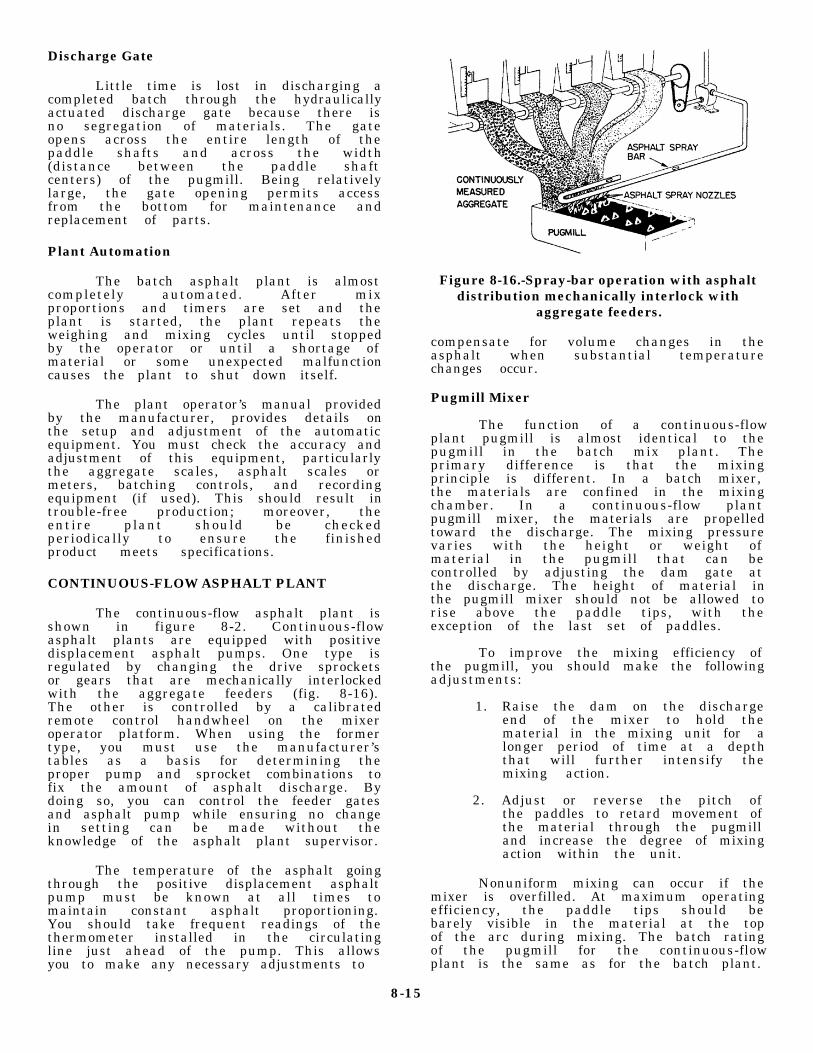
Discharge Gate
Little time is lost in discharging acompleted batch through the hydraulicallyactuated discharge gate because there isno segregation of materials. The gateopens across the entire length of thepaddle shafts and across the width(distance between the paddle shaftcenters) of the pugmill. Being relativelylarge, the gate opening permits accessfrom the bottom for maintenance andreplacement of parts.
Plant Automation
The batch asphalt plant is almostcompletely automated. After mixproportions and timers are set and theplant is started, the plant repeats theweighing and mixing cycles until stoppedby the operator or until a shortage ofmaterial or some unexpected malfunctioncauses the plant to shut down itself.
The plant operator’s manual providedby the manufacturer, provides details onthe setup and adjustment of the automaticequipment. You must check the accuracy andadjustment of this equipment, particularlythe aggregate scales, asphalt scales ormeters, batching controls, and recordingequipment (if used). This should result introuble-free production; moreover, theentire plant should be checkedperiodically to ensure the finishedproduct meets specifications.
CONTINUOUS-FLOW ASPHALT PLANT
The continuous-flow asphalt plant isshown in figure 8-2. Continuous-flowasphalt plants are equipped with positivedisplacement asphalt pumps. One type isregulated by changing the drive sprocketsor gears that are mechanically interlockedwith the aggregate feeders (fig. 8-16).The other is controlled by a calibratedremote control handwheel on the mixeroperator platform. When using the formertype, you must use the manufacturer’stables as a basis for determining theproper pump and sprocket combinations tofix the amount of asphalt discharge. Bydoing so, you can control the feeder gatesand asphalt pump while ensuring no changein setting can be made without theknowledge of the asphalt plant supervisor.
The temperature of the asphalt goingthrough the positive displacement asphaltpump must be known at all times tomaintain constant asphalt proportioning.You should take frequent readings of thethermometer installed in the circulatingline just ahead of the pump. This allowsyou to make any necessary adjustments to
Figure 8-16.-Spray-bar operation with asphaltdistribution mechanically interlock with
aggregate feeders.
compensate for volume changes in theasphalt when substantial temperaturechanges occur.
Pugmill Mixer
The function of a continuous-flowplant pugmill is almost identical to thepugmill in the batch mix plant. Theprimary difference is that the mixingprinciple is different. In a batch mixer,the materials are confined in the mixingchamber. In a continuous-flow plantpugmill mixer, the materials are propelledtoward the discharge. The mixing pressurevaries with the height or weight ofmaterial in the pugmill that can becontrolled by adjusting the dam gate atthe discharge. The height of material inthe pugmill mixer should not be allowed torise above the paddle tips, with theexception of the last set of paddles.
To improve the mixing efficiency ofthe pugmill, you should make the followingadjustments:
1. Raise the dam on the dischargeend of the mixer to hold thematerial in the mixing unit for alonger period of time at a depththat will further intensify themixing action.
2. Adjust or reverse the pitch ofthe paddles to retard movement ofthe material through the pugmilland increase the degree of mixingaction within the unit.
Nonuniform mixing can occur if themixer is overfilled. At maximum operatingefficiency, the paddle tips should bebarely visible in the material at the topof the arc during mixing. The batch ratingof the pugmill for the continuous-flowplant is the same as for the batch plant.
8-15

Figure 8-17.-Basic drum-mix asphalt plant
Mixing Time
Total mixing time begins when allthe combined mineral aggregates are in themixer and ends when the mixer dischargegate is opened. Dry mixing time, whenspecified, begins when all the combinedmineral aggregates are in the mixer andends with the introduction of the asphalt.Wet mixing time begins with the start ofthe asphalt application and ends with theopening of the mixer discharge gate.
The asphalt film on aggregate ishardened by exposure to air and heat;therefore, mixing time should be theshortest time required to obtain a uniformdistribution of aggregate sizes and auniform coating of asphalt on allaggregate particles. The speed of themixer shafts and the arrangement and pitchof the paddles are factors governing theefficiency of the mixing.
To aid further the operation of acontinuous mix plant, you can add orextend several automatic controls.These include the following:
1. Automatic burner controls
2. Automatic mix discharge
3. Automatic mixer and gradationcutoffs in case of hot-bin shortage orimproper feed
4. Electric interlocks that shutdown the complete plant in case of afailure anywhere in the electric system
The operator’s manual for theparticular plant being used gives detailson the setup and adjustments of theautomatic equipment included with theplant.
NOTE: Normally all automaticsystems have manual override. You shouldknow where it is located and how to useit. See the manufacturer’s manual forspecific details.
DRUM-MIX ASPHALT PLANT
The drum-mix plant is shown infigure 8-3. The mixing drum for which theplant is named is very similar inappearance to the batch plant dryer drum.The difference between the two is that ina drum-mix plant the aggregate is not onlydried and heated within the drum, but itis also mixed with the asphalt cement. Ina drum-mix plant, there are no gradationscreens, hot bins, weigh-hoppers orpugmills. Aggregate gradation iscontrolled at the cold feed.
The basic plant consists of a cold-feed system, a rotating drum dryer, anasphalt proportioning and dispensingsystem, and a surge silo (fig. 8- 17). Theease of setup and operation of the drum-mix plant makes it the ideal machine foroperations.
Aggregate Storage and Feed
Aggregate gradation and uniformityare entirely dependent on the cold-feedsystem. Proper care must be exercised notonly in producing the aggregate but alsoin storage. Aggregates used for drum-mixplants must be received, handled, andstored to ensure there is no danger ofcontamination or intermingling.
Stockpiles must be properly gradedand split into different sized fractionsto control the gradation of the mixproperly. Uncorrected segregatedstockpiles will result in mix gradationdifficulties. The plant supervisor shouldestablish and maintain stockpiles in themost economical manner and correct anydeficiencies in uniformity before theaggregate is fed into the mixing plant.
Since the typical drum-mix plantdoes not have a gradation unit, theaggregate must be proportioned beforeentering the mixing drum. This isaccomplished with a multiple-bin cold-feedsystem equipped with precision beltfeeders for control of each aggregate.
8-16

Under each bin is a belt feeder upon which the aggregateis proportioned.
The plant should be equipped with a means to obtainsamples of the full flow of aggregates from each coldfeed and the total cold feed. These samples are requiredto perform a sieve analysis of the dried aggregate.
Cold feed controls consist of the following:
1. Sieve analysis of aggregate in each bin.
2. Calibrate feeders–both belt speed and gateopening.
3. Established bin proportions.
4. Set belt drive speeds and gate openings.
Once the gates are calibrated, they should bechecked regularly to ensure they remain properly set.All settings should be considered tentative because thecold aggregate used in the mix normally varies ingrading and moisture content; therefore, adjustment ofthe gates is required to maintain a uniform flow.
Drum-mix plants require the use of a continuousweighing system on the cold-feed conveyer belts.In-line belt weighers, known as weigh bridges, arebelt-weighing devices used to weigh the combinedaggregate passing over the conveyer belt. A readoutindicates the weight of the flow over the scales at anygiven instant. No material should ever be diverted fromthe conveyer belt after it passes the belt weigher.
The in-line belt weigher is usually located betweenthe head and tail pulley of the cold-feed belt conveyer,This location tends to lessen variations in readingscaused by impact loading, rollback of aggregate, orchanges in belt tension.
In drum-mix plants the aggregate is weighed beforedrying. Undried aggregates may contain an appreciableamount of moisture that can influence the weight;therefore, an accurate measurement of the moisturecontent is important. From the weight measurement,adjustments can be made to the automatic asphaltmetering system to ensure that the amount of asphaltdelivered to the drum is correct for the amount ofaggregate minus its moisture content.
The moisture content of the cold-feed aggregatesshould be monitored at the beginning of each day andabout the middle of the day. When conditions make themoisture content vary, it should be checked morefrequently.
Figure 8-18.-Drum mixer zones
Asphalt Metering
The drum-mixer is normally equipped with a systemto add asphalt to the aggregate inside the drum mixer.Called the asphalt metering and delivery system, it is acontinuous mechanical proportioning systeminterlocking with the aggregate weigh system to ensurethe exact asphalt content of the mix. The weight of theaggregate delivered into the mixer, as measured by theweigh belt, is the basis for determining the quantity ofasphalt delivered into the drum.
Asphalt proportioning is accomplished byestablishing the necessary rate of asphalt delivery ingallons per minute to match the aggregate delivery intons of dry aggregate per hour. The asphalt delivery rateis adjusted to correspond to the weight measurement ofthe aggregate prosing over the belt scale.
Drum-Mix Operation
The mixer is the heart of a drum-mix plant.Compared to a conventional batch plant rotary dryer, themixer is similar in design and construction except thatthe drum-mixer can be divided into two sections: (1) aprimary or radiation zone and (2) a secondary orconvention/coating zone (fig. 8-18).
Aggregates enter the primary zone where heat fromthe burner dries and heats it. Then the aggregate movesto the secondary zone where asphalt is added, andaggregates and asphalt are thoroughly blended.Continued drying also occurs in the secondary zone. Themixture of hot asphalt and moisture released from theaggregate produces a foaming mass that traps the finematerial (dust) and aids in the coating of the largerparticles.
Drum-mixers are equipped with flights to direct theaggregate flow and spread the aggregates into a veil
8-17

across the cross section of the drum. The aggregatesmust not only rotate with the revolving motion of thedrum but must also spread out sufficiently to makeheating and drying of all particles quick and efficient.
The spiral flights are located at the charging(burner) end of the drum-mixer and direct wetaggregates into the drum in such a manner as to attainuniform drum loading. Tapered lifting flights pick up theaggregates and drop them in an even veil through theburner flame.
Burner Operation
The burner inside the drum-mixer provides the heatnecessary to heat and dry the aggregates used in the finalmixture. The burner provides this heat by burning fueloil, gas, or both.
When oil is burned, a low-pressure air draft is usedto atomize the fuel oil for burning. Depending on thetype of fuel used for the burners, the fuel feed and airblower must be balanced to ensure that the properproportions of fuel and air are being introduced into theburner to ensure efficient combustion. Lack of balancecan lead to incomplete burning of the fuel. Especially,when fuel oil or diesel fuel is used, this can leave an oilycoating on the aggregate particles. An imbalancebetween the fuel feed and air flow can be adjusted byeither decreasing the fuel rate or increasing the bloweror draft air.
Surge Silo
The drum-mix plant produces a continuous flow offresh asphalt hot mix and has a surge silo for temporarystorage of the hot-mix material. The surge silo is alsoused for controlled loading of trucks. A weight systemis normally connected to the holding bin of the silo tomonitor the amount of hot mix loaded into each truck.Weight measurements are normally recorded by theweight system control panel.
BITUMINOUS SURFACINGMATERIALS
Bituminous materials are tremendously importantin the construction of roads and airfields for bothmilitary and civilian use. A basic knowledge of thesebituminous materials, their origin, composition, types,and grades are essential for an understanding of their usein construction.
Bituminous surfaces are composed of compactedaggregate and bitumen (binder). The aggregate
transmits the load from the surface to the subgrade, takesthe abrasive wear of the traffic, and provides a nonskidsurface. The binder binds the aggregate together, thuspreventing the displacement and loss of the aggregate.The binder also provides a waterproof cover for the basethat keeps surface water from seeping into andweakening the material.
Bituminous surfaces are particularly adaptable tostage construction. Additional courses can be added toexisting pavements to provide further reinforcementwhen loads or traffic density increases. The flexibilityof bituminous surfaces permits slight adjustment causedby settlement of the subgrade without detrimental effect.Properly designed bituminous wearing surfaces, whencompared with concrete, are less affected bytemperature strains. The surfaces resist wear,weathering, and deterioration from aging with onlyminimal maintenance.
Bituminous materials are highly versatile and serveadmirably in temporary, expedient, and light trafficsituations where concrete is not justifiable. It is equallytrue that thicker bituminous pavement designed forheavy and continuing duty is fully comparable toconcrete designed for heavy volumes of traffic or heavywheel loads; however, bituminous wearing surfaceslack appreciable bearing action to carry wheel loadsover weak spots in the subbase. For this reason, thesubgrade must have an adequate, uniform bearingstrength and the base course must have adequatethickness, bearing capacity, and cohesion.
TYPES AND GRADES OF ASPHALT
Asphalt is a natural or man-made by-product ofpetroleum distillation. Natural asphalt is found in natureas either lake (or pit) asphalt or rock asphalt. Thecommon bituminous surfacing materials are asphaltcements, asphalt cutbacks, asphalt emulsions, road tars,and road tar cutbacks. For identification purposes, thesematerials are divided into three classes: asphaltbitumens, emulsions, and tars. The classification ofthese materials is based on the extent to which theydissolve in a distillate of petroleum or coal. Asphaltcements and asphalt cutbacks are asphalt bitumens (orasphalts). Road tars and road tar cutbacks are tars.
Asphalt Cements
Asphalt cements are solid products of petroleumrefining (fig. 8-19). An asphalt cement is designated bythe letter symbol AC, followed by the penetration gradethat represents its relative hardness. The numbers range
8-18

Figure 8-19.-Petroleum asphalt flow chart.
8-19

Table 8-2.-Penetration Grade and AP Number of Asphalt Cement
Table 8-3.-AsphaIt Cutback Composition (Expressed in Percent of Total Volume)
from 40 (hard) to 300 (soft) (table 8-2). The number isderived from a penetration test that is the distance thata standard needle penetrates the asphalt cement under astandard loading weight, in a given time, under knowntemperature conditions.
All asphalt cements are solid or semisolid at roomtemperature (77°F) and must be converted to a fluid formixing with aggregate or for spraying. Asphalt cementmust be heated to a temperature ranging from 250°F to350F, depending upon the grade of the asphalt cement.
The various penetration grades of asphalt cementare suitable for different uses, such as plant mixes,penetration macadam, and surface treatment. Softpenetration grades of asphalt cement are preferred foruse in cold climates, medium grades in moderateclimates, and had grades in warm climates.
Asphalt Cutbacks
The special equipment needed to heat asphaltcements is not always available. Since asphalt must be
in a fluid condition to spray or to mix with an aggregate,
the solid asphalt cement would not be suitable. Asphalt
cement (AC) can be made fluid by adding solventscalled Cutterstock or Flux Oil. Cutterstock maybe anyone of the more volatile petroleum distillate products.
The resulting combination is called Asphalt Cutback.
Exposure to air causes the petroleum distillate to
evaporate and leave the asphalt cement to perform its
function.
The rate of evaporation determines the type of
asphalt cutback that is in the mixture. Gasoline ornaphtha (highly volatile) will produce a rapid-cure
cutback (RC) with a curing time of 4 to 8 hours; kerosene
(medium volatility) will produce a medium-curing
cutback (MC) with a curing time of 12 to 24 hours; and
a fuel oil (low volatility) will produce a slow-curing
cutback (SC) with a curing time of 48 to 60 hours, Table
8-3 shows the percentage of components by grade for
the three types of asphalt cutbacks.
8-20

Table 8-4.-Asphalt Emulsions According to Their Electric Charge
Grades of Asphalt Cutbacks
When a great amount of cutterstock is added to agiven amount of asphalt cement, a very thin liquidresults. Viscosity grade is a measure of the relativeconsistency of an asphalt bitumen after cutterstock isadded to a fixed amount of it. The grade is designatedby a number that corresponds to the lower limit of theviscosity of asphalt cutback as determined by a standardtest. The upper limit of viscosity is defined as twice thelower limit.
The viscosity grades of RC, MC, and SC are 70(70-140), 250 (250-500), 800 (800-1,600), and 3,000(3,000-6,000). The numbers in parenthesis are the lowerand upper limits of viscosity, In addition, MC has a grade30(30-60). The grade ranges are 30 (most fluid) to 3,000(least fluid).
Uses of Asphalt Cutbacks
Different types and grades of asphalt cutbacks areused to meet various climate conditions for differenttypes of pavement. Asphalt cutbacks are usually usedfor prime/tackcoats and for bituminous surfacetreatments. The prevailing atmospheric temperaturesexisting during construction projects are a major factorin selecting the grade of asphalt cutback. The heaviergrades are preferred for use in warm weather; the lightergrades in cool weather. When the preferred grade of agiven type of asphalt cutback is not available, acomparable grade of another type may be substituted;for example, RC-800 maybe used instead of MC-800,or RC-70 instead of MC-70, without seriously affectingthe finished pavement.
Light grades of asphalt cutback maybe produced inthe field by adding solvents to asphalt cutback. Thecomposition of asphalt cutbacks, expressed in percentof total volume, is shown in table 8-3.
Asphalt Emulsions
An asphalt emulsion is a nonflammable liquidsubstance, composed of asphalt cement, water, and anemulsifier mixed together to produce a liquid material.Emulsions are environmentally friendly, have the samebasic uses as cutbacks and are becoming morecommonly used in the field. Asphalt and water will notmix; therefore, a chemical agent called an “emulsifyingagent” must be added. The emulsifying agent keeps theasphalt cement suspended in the water and controlscertain physical properties of the emulsion. Commonemulsifying agents are soaps, animal blood chemicals,and certain specified colloidal clays in dust. Whenemulsion is applied to a surface, the water and asphaltcement break (separate), leaving a thin film of asphaltcement.
The speed of separation, referred to as setting rate,is the basis for designating an asphalt emulsion. Thesetting rates are rapid, medium, and slow. The lettersymbols for these rates are RS, MS, and SS,respectively.
Asphalt emulsions are classified into two types:those that are negatively charged and those that arepositively charged (table 8-4), Emulsified asphalts maybe of either the anionic electro (negatively) chargedasphalt globules or cationic electro (positive) chargedasphalt globules. The asphalt emulsions are graded onthe basis of viscosity and grouped according to their use.
8-21

Figure 8-20.—Tars obtained from distillation of bituminous coal.
The viscosity grades range from 1 (leastfluid) to 3 (most fluid).
Use of Asphalt Emulsions
Emulsions are used for surfacetreatment, road and plant mixes, and crackand joint filling. The mixing grades canbe mixed unheated with damp aggregate.They are preferred over asphalt cutbackwhen the aggregate is very damp. Cationicemulsions coat damp aggregate better thananionic emulsion.
Recommended use of emulsionsdepends on setting rate and mixingabi l i ty . At water - f reez ingtemperatures, asphalt emulsions donot mix well since the emulsion willseparate from the water. Also,emulsions have a relatively shortshelf life and tend to break whilestill in their unopen drums.
Tars
Tars are obtained from the distillation ofbituminous coal (fig. 8-20) and are seldom used inthe NCF. A road tar is designated by the symbol RTand is manufactured in 12 grades of viscosity(table 8-5). RT-1, RT-2, and RT-3 are PRIMINGOIL. RT-4 through RT-7 are called COLD TARSbecause they are fluid enough to be mixed andapplied at relatively low temperatures. RT-8through RT-12 are called HOT TARS because theyare solid enough to require high temperatures formixing and applying.
The symbol RTCB refers to ROAD TARCUTBACK. RTCBs are manufactured only inviscosity grades 5 and 6. Coal distillate,such as benzene or a solution ofnaphthalene in benzol, may be used tocutback the heaviest grades of road tar toproduce both grades of road tar cutbacks.The viscosity grades of road tars and roadtar cutbacks can be compared to the
8-22

Table 8-5.-Viscosity Grades at Room Temperature
viscosity grades of asphalt cutbacks andasphalt cements by means of table 8-5.
Use of Tars
Tars are suitable for use on areaswhere asphalt is unsuitable. A goodexample is an airfield where petroleumdistillates are likely to be spilled. Tarsdo not strip easily from aggregate in thepresence of water and is preferred as aprime coat. Tars penetrate more deeplyinto the base course than will asphalt ofthe same viscosity and curing rate.
Cold-tar mixes are used for road mixand patching. Hot-tar mixes are used forplant mix, surface treatment, crackfillers, and similar uses. Since tarsbecome soft at high temperatures andbrittle at low temperatures, the heaviergrades are preferred for use in warmweather and the lighter grades in coolweather.
Road tar cutbacks are used forpatching mixes; however, an open flamemust NOT be used near storage tanks anddrums of road tar cutbacks because theyare flammable.
FIELD IDENTIFICATION OFBITUMINOUS MATERIALS
Identifying bituminous materials canbe a problem. Stockpiled bituminousmaterials that are unmarked or improperlymarked can cause unnecessary delays inconstruction operations. Fairly accurateidentification is necessary to decide onthe type of construction that thematerials can be used for, the method ofconstruction to be used, the type andquantity of equipment needed, and theapplicable safety regulations to beobserved. Some of the tests used in thefield to identify bituminous materials asasphalt cement, asphalt cutback, asphaltemulsion, road tar, or road tar cutbackare as follo ws:
• Solubility
• Pour
• Smear
• Heat-Odor
• Penetration
• Stone coating
8-23

Figure 8-21.—Field identification of unknown bituminous materials.
Field identification of bituminousmaterials is summarized in figure 8-21.
Solubility Test
The solubility test consists oftaking a small amount of the unknownbituminous material, enough to cover thehead of a nail if a solid, or few drops ofa liquid material and attempting todissolve the material by stirring it in apetroleum distillate; gasoline, kerosene,
diesel fuel, and so forth. If the materialis an asphalt, it will mix uniformly withthe distillate. Tars, however, will form astringy undissolved mass. Emulsions, inaddition to other distinguishing tests,may also be identified in the solubilitytest since they will form undissolvedballs or beads of the emulsion at thebottom of the container of petroleumdistillate. The solubility test provides apositive method of identification (fig. 8-22).
8-24

FROM LEFT TO RIGHT: KEROSENE,KEROSENE PLUS TAR, KEROSENE PLUSASPHALT CEMENT OR ASPHALT CUTBACK.
BEADS FORMED BY ASPHALT EMULSION INKEROSENE.
Figure 8-22.—Solubility test for asphalt, tar,and emulsion.
Pour Test
When you perform the volubility testand the bituminous material dissolves, anasphalt product–asphalt cement or asphaltcutback–is present. At room temperature(77 F) asphalt cements are solids, and asphaltcutbacks are fluids. With these facts in mind,you may run a second test, a pour test, todetermine whether a sample is an asphaltcement or an asphalt cutback.
In the pour test, an attempt is made to pourthe material from a small container. Asphaltcements are solids and will not pour. Asphaltcutbacks are fluids at 77 F and will pour (fig. 8-23).
A pour test is also used to identify the 12viscosity grades of tar. Viscosity grades of road tarare comparable to the viscosity grades of asphaltcutbacks and asphalt cement (table 8-5). RT-1, themost fluid, is similar in viscosity to the grade 30 ofthe rapid-curing, medium-curing, and slow-curingtypes of asphalt cutbacks. RT-8 is similar to grade800 asphalt cutback. RT-12 has the approximateconsistency of asphalt cement of 200-300penetration.
Road tar grades 4, 5, and 7, which are identicalin appearance to road tar cutback grades 5 and 6 may bedistinguished through a smear test. Like asphalt
ASPHALT CEMENT ON LEFT.ASPHALT CUTBACK ON RIGHT.
LEFT TO RIGHT: ASPHALT CUTBACKS GRADE30, 70, 250, 800, AND 3,000 THREE SECONDS
AFTER TIPPING FULL JARS.
THIRTEEN SECONDS AFTERTIPPING FULL JARS.
143.179Figure 8-23.—Pour test for asphalt
and cutbacks.
cutbacks, road tar cutbacks cure rapidly since theyare thinned with highly volatile materials thatevaporate quickly and leave a sticky substance withina 10-minute period. On the other hand, because thefluid coal oil in road tars evaporates slowly, road tarswill remain at the same consistency at the end of anidentical period.
8-25

Figure 8-24.–Smear test of asphalt cutback.
Smear Test
The smear test is used to separatean RC from an MC or SC. The test isprimarily based on the fact that RCs arecutback with a highly volatile material(naphtha or gasoline). You can determinewhether a sample is an RC or not bysmearing some of the sample in a thinlayer on a nonabsorbent surface, such as apiece of glazed paper. The volatilesubstance evaporates within a few minutesand the surface becomes so tacky that whentouched, the specimen, paper and all,sticks to your fingers and can be liftedinto the air (fig. 8-24).
Checking the reverse side of thepaper, you will find that the RC did notpenetrate through the paper as MCs or SCsdo. MCs and SCs on smear tests remainfluid and oily for time periods that varyfrom hours to days, depending on the typeand grade of material. If an 800 or 3,000grade MC or SC is present, they may becomesticky in a few minutes since there issuch a small amount of cutterstock inthem. When such a viscous grade ispresent, it is well to confirm theidentification of the sample by a prolongedsmear test. Generally, the MCs and SCs willpenetrate through the paper while the RCswill not. You can determine this byobserving the back side of the paper.
In a prolonged smear test, a thinsmear is made on nonabsorbent paper andallowed to cure completely. If the viscouscutback is all RC-3000, it will curecompletely in about 3 hours. When the spothas cured completely (the cutterstock hasalmost all evaporated), the smear willbe almost pure asphalt cement (AC) andwill be hard and no longer sticky. Ifthe viscous sample were an MC or SC-800 or 3,000, the spot would still be
Figure 8-25.—Stone-coating test for emulsions.
uncured and, therefore, very sticky, evenafter 24 hours, while the RC smear willhave become a hard, glazed spot.
Heat-Odor Test
A heat-odor test is used todistinguish between medium-curing andslow-curing asphalt cutback by identifyingthe cutter stock as kerosene, fuel oil, ordiesel oil. A sample of the material isheated in a closed container to retain thevapors. (CARE MUST BE TAKEN TO AVOID THEUSE OF TOO MUCH HEAT). Medium-curingasphalt cutback will have a strong odor ofkerosene. Slow-curing asphalt cutback willlack the kerosene odor, but a faint odorof motor oil may be present.
Field Penetration Test
The field penetration test isperformed to determine the approximatehardness of the asphalt, not to pinpointthe exact penetration number for it. Todetermine if the number falls in the hard,medium, or soft group is sufficient.
To perform this test, attempt topush a sharpened pencil or nail into thecontainer of asphalt (at about 77°F),using a firm strong pressure ofapproximately 10 pounds. If only a slightpenetration is made with considerabledifficulty, a hard asphalt cement ispresent. When the penetration is madeslowly but without great difficulty, amedium asphalt cement is present. If thepenetration is made with ease, the asphaltcement is a high penetration scale (a softAC).
Stone-Coating Test
When a material has been tested andfound to be an emulsion, the stone-coatingtest is performed (fig. 8-25). This test isconducted to determine if the emulsion is a
8-26

Figure 8-26.-Water-mixing test for emulsions.
rapid setting emulsion termed a nonmixinggrade or a medium- or slow-settingemulsion termed as mixing grade emulsion.To know which type is present isimportant because the applications ofthe mixing and nonmixing types varygreatly. The test performed todistinguish between these two types ofemulsions is the stone-coating test.This test consists of taking a handfulof damp sand and adding to the sand asmall amount of emulsion (estimate about6 to 8 percent by weight) and attemptingto mix the two materials. Care should beexercised not to add so much emulsionthat the sand becomes saturated.
A rapid-setting emulsion will“break” so quickly it will not be possibleto mix it with sand. It breaksimmediately, gumming up the mixing spoonand the aggregate with asphalt cement;otherwise, if the unknown sample is amedium- or slow-setting emulsion whenadded to the damp sand, it will mix easilyand coat all the particles completely aswell as the mixing spoon with a uniformcoating of asphalt. Identification of anemulsion merely as a mixing or nonmixingtype is sufficient for field conditions.The difference in viscosity is unimportantbecause there are so few grades. Nodistinction is necessary between medium-and slow-setting emulsions since both aremixing types used largely for the samepurpose.
Another test for emulsions is theWATER-MIXING TEST (fig. 8-26). Becauseemulsions are made with water, more watermay be added to emulsions withoutdisturbing the uniformity of the liquid.None of the other bituminous materialswill dissolve in water.
A FLAME TEST can also be used intesting asphalt emulsions. A clothsaturated with asphalt emulsion willsmolder but will not burn or burst intoflame. Other bituminous materials arecombustible.
Laboratory Test of Bituminous Materials
In addition to the field tests,various tests are performed on bituminousmaterials in the laboratory. These testsusually are made for the purpose ofchecking compliance with the establishedspecifications; however, laboratory testsmay also be made to identify the materialbeyond field identification, to furnishinformation for mix design, or toestablish safe handling procedures.
Bituminous materials are produced tomeet the specification established by thefederal government, the AmericanAssociation of State Highway Officials(AASHO), and the American Society forTesting Materials (ASTM). Thesespecifications define the extreme limitspermitted in the manufacture of thematerial and assure the user that thematerial will possess definitecharacteristics and fulfill the projectrequirements. Consult with the EAs for theproper specifications required.
ESTIMATION OF MATERIALS
Many different combinations ofmaterials are used on bituminous surfaces.Before a bituminous surface is placed, thesurface to be covered normally requiresthe placing of a preliminary treatment: aprime or a tack coat.
Prime Coat
Prime coats are placed on a dirt orgravel surface. The purpose of priming isto waterproof and dustproof the surface,plug capillary voids, and coat and bondloose particles. A prime coat also hardensor toughens the surface, promotes adhesionbetween the existing surface and the newsurface, and penetrates the surface.The priming material may be one of thefol lowing:
• A low-viscosity tar, such as RT-2,RT-3, or RT-4
• A low-viscosity asphalt,such as MC-30, -70, -250, orSC-70 , -250,-80 0
• A diluted asphalt emulsion
Bituminous materials used for theprime coat should be applied in quantitiesknown as the rate of application (ROA) ofnot less than 0.2 gallon or more than 0.5gallon per square yard. Normally, theconstruction project specifications denotethe ROA for the prime coat application;however, when the ROA is not included inthe project specifications, the NCF usesan ROA of .3 for planning purposes.
8-27

To estimate the amount of bitumen required for theprime coat, multiply the area to be treated by the rate ofapplication. Under certain conditions, the estimateshould include sufficient bitumen for an additionalwidth of 1 foot on each side of the surface course to beconstructed on the primed base.
The formulas for a prime coat estimate are as follows:
For computing gallons:
For computing drums:
Tack Coat
A tack coat is a coating of asphalt on an existing pavedsurface that provides a bond between the existing surfaceand the new surface, The two essential properties of a tackcoat are as follows: (1) it must be very thin and (2) it mustuniformly cover the entire surface of the area When tack
8-28
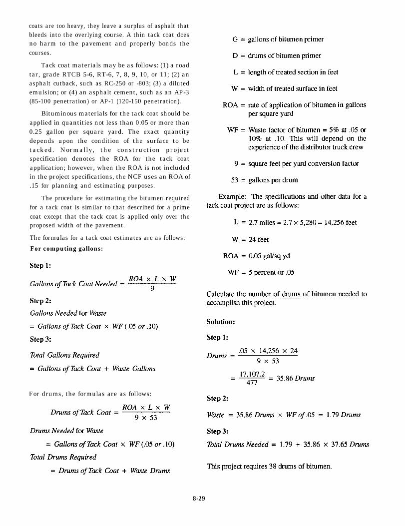
coats are too heavy, they leave a surplus of asphalt thatbleeds into the overlying course. A thin tack coat doesno harm to the pavement and properly bonds thecourses.
Tack coat materials may be as follows: (1) a roadtar, grade RTCB 5-6, RT-6, 7, 8, 9, 10, or 11; (2) anasphalt cutback, such as RC-250 or -803; (3) a dilutedemulsion; or (4) an asphalt cement, such as an AP-3(85-100 penetration) or AP-1 (120-150 penetration).
Bituminous materials for the tack coat should beapplied in quantities not less than 0.05 or more than0.25 gallon per square yard. The exact quantitydepends upon the condition of the surface to betacked. Normally, the construction projectspecification denotes the ROA for the tack coatapplication; however, when the ROA is not includedin the project specifications, the NCF uses an ROA of.15 for planning and estimating purposes.
The procedure for estimating the bitumen requiredfor a tack coat is similar to that described for a primecoat except that the tack coat is applied only over theproposed width of the pavement.
The formulas for a tack coat estimates are as follows:
For computing gallons:
For drums, the formulas are as follows:
8-29

Surface Treatment
Bituminous materials and aggregate are combinedin various proportions to obtain the most satisfactorysurface for a given situation. Accurate estimates arerequired to avoid production delays because ofinadequate supplies. You also want to avoid oversupplyand waste of materials.
The formulas for estimating supplies for a single-surface treatment are as follows:
For computing pounds:
For computing tons:
determined by the same method as above except theThe materials for a multiple-surface treatment are
application rate of the binder and the aggregate, and thesize of the aggregate for the second lift is one half of thatof the first lift.
Example: A test strip with an area of 100 squareyards was used to determine the quantities for asingle-surface treatment. Careful control was made ofmaterials. A check of materials consumed showed that1.50 tons of aggregate was used. Based on previousexperience, an aggregate loss of 10 percent (0. 10) and abitumen loss of 5 percent (0.05) are expected. Find thetons of aggregate and gallons of bitumen necessary tomake a double-surface treatment on a road 24 feet wideand 10 miles long.
8-30

Compute Bituminous Material
Several methods are used to calculate the amount ofhot-mix material required for paving projects; however,when the weight of a hot-mix per square yard or cubicfoot is not known, two equations are used in the NCF tocompute the number of tons of asphalt required for aproject. These equations are as follows:
Equation 1
= Percent of Tons + Tons = Tons Required
Where:
L = length of project in feet
W = width of project in feet
D = depth or thickness of compacted mat. Youmust change inches into feet by dividingthe number of inches by 12 (inches in 1foot). For paver screed height, add 1/8inch for each inch of the mat to be paved.(Example: for a 2-inch mat, two blocks ofwood 2 1/4 inch thick will be required toset under the screed.) The blocks must bethicker than the finished compacted matto allow for additional compaction byrollers
146 = This number represents the approximateweight of 1 cubic foot of compactedhot-mix asphalt. This number can varyfrom 140 to 160 pounds; however,146 pounds equals the 110 pounds persquare yard per 1-inch depth of asphaltused in the second equation for figuringtons require for asphalt. (See table 8-5.)
WF = Waste factor equals 5% or .05, or 10% or.10, depending on the experience of thescreed operators and handwork requiredon the project
2,000 = 2,000 pounds is equal to one ton;therefore, you must divide the totalweight of material by 2,000, giving tonsrequired.
8-31

Table 8-6.-Weight and Volume Relations for Various Types of Compacted Asphalt Pavement.
110 = Pounds per square yard of asphalt per 1inch depth. (Example: A 2-inch mat willequal 220 pounds per square yard.)
9 = To obtain square yards from square feet,divide by 9
2,000 = 2,000 pounds equal one ton; therefore,you must divide the total weight ofmaterial by 2,000, giving tons required.
WF = Waste factor equals 570 or .05, or 10% or.10, depending on the experience of thescreed operators, and handwork requiredon the project.
Example: The specifications for a parking lotpaving project are as follows:
L = 90 feet
W = 30 feet
D = 2 inches
WF = .10
8-32

Find the amount of asphalt required for this project.
Solution:
Estimates for Asphalt Plants
The amount of materials comprising the plant mixcan be best determined by a proportionate method. Thisis demonstrated by the following example:
Example: The required tonnage of plant mix for aproject is 800 tons. The aggregate blend is 50/40/10(percentage coarse aggregate/fine aggregate/mineral
filler). The bitumen content is 6 percent. How many tonsof each aggregate are required?
The job mix formula is as follows:
= Adjusted Percent of AGG
OAC = Optimum Bituminous (Asphalt) Content
Solution:
Total aggregate percent by weight= 100 – 6 = 94percent, or 0.94.
Coarse/aggregate = 0.94 x 50 percent = 47.0 percentby weight of the total mix.
Fine aggregate = .094 x 40 percent = 37.6 percentby weight of the total mix.
Mineral filler = 0.94 x 10 percent = 9.4 by weightof the total mix.
To convert to tons, multiply the required tonnage ofplant mix by the percentage of each component of themix. The results should be adjusted so that the sum ofthe tonnage of components is equal to the requiredtonnage of plant mix.
Coarse aggregate = 800 x 0.470 = 376.0 tons
Fine aggregate = 800 x 0.376 = 300.8 tons
Mineral filler = 800 x 0.094 = 75.2 tons
Bitumen = 800 x 0,060 = 48.0 tons800 tons
(The bitumen weight was calculated as a check.)
Tons per hour
The equation used to compute the amount of asphaltthat can belayed with a paver per hour is as follows:
Tons per hour =L x W x D x 146
2000x 6 0
Where:
L = Feet per minute. The NCF uses 11 feet perminute for planning purposes,
W = Width of the paver screed
D = Depth or thickness of compacted mat
146 =This number represents the approximateweight of 1 cubic foot of compactedhot-mix asphalt
60 = 60 minutes in one hour
2000 = There are 2,000 pounds in 1 ton
Example: The required tonnage of hot-mix asphaltfor a project is 800 tons. The screed of the paver is setat 10 feet, and the depth of asphalt is 2 inches. Estimatethe amount of asphalt that can be laid per hour.
Solution:
11 x 10 x .167 x 146 x 60 = 160921.22000 2,000
160921.22,000
= 80.46 tons per hour
By planning and estimating the amount of hot-mixasphalt that can be laid per hour, you are able to tell theasphalt plant exactly how much hot-mix asphalt isrequired to be delivered per hour and/or per day.
8-33

ASPHALT PLANT SAFETY
You must always be safety conscious and on thealert for potential dangers to personnel and property.Safety considerations cannot be overemphasized.
Coal distillate, such as benzene or naphthalene inbenzol, are suspected carcinogens. Avoid all skincontact and do not inhale the vapors and gases fromthese distillates. Asphalt contains componentssuspected of causing cancer. Anyone handling asphaltmust be trained on the health hazards.
Dust is particularly hazardous because of its threatto your lungs and eyes. Additionally, dust contributesgreatly to poor visibility when trucks, front-end loaders,or other equipment are being used around the stockpilesor cold bins. Reduced visibility in work traffic is a primecause of accidents.
Noise can be a double hazard. Noise is not onlyharmful to your hearing but also distracts your attentionfrom moving equipment or other dangers.
Moving belts transporting aggregates should be aconstant concern, as should belts to motors and sprocketand chain drives. All pulleys and belts and drivemechanisms should be covered or otherwise protected.Loose clothing that can get caught in machinery shouldnever be worn at an asphalt plant.
Good housekeeping is essential for plant safety. Theplant and yard should be kept free of loose wire or lines,pipes, hoses, or other obstacles. High-voltage lines, fieldconnections, and wet ground surfaces are other hazards.Anyloose connections, grayed insulation, or improperlygrounded equipment should be reported immediately.
Plant workers should not work on stockpiles whilethe plant is in operation. Personnel should NOT walk orstand on the stockpiles or on the bunkers over the feedergate openings. Many workers have been pulled down
into the material and buried alive so quickly that nothingcould have been done to save them.
Burner flame and high temperatures around plantdryers are obvious hazards. Control valves that can beoperated from a safe distance should be installed on allfuel lines. Flame safety devices also should be installedon all fuel lines. Smoking should not be permitted nearasphalt or fuel storage tanks. Check frequently for leaksin oil heating lines and steam lines or jacketing on theasphalt distribution lines. Be sure safety valves areinstalled in all steam lines, and they are in working order.Make use of screens, barrier guards, and shields forprotection from steam, hot asphalt, hot surfaces, andsimilar dangers.
When you are handling heated asphalt, use chemicalgoggles and a face shield. All shirt collars should beworn closed and cuffs buttoned at the wrist. Gloves withgauntlets that extend up the arm should be worn looselyso that they can be flipped off easily if they becomecovered with hot asphalt. Pants should remain bloused.
Exercise extreme care when climbing around thescreen deck. All stairs and platforms should have securehandrails.
Hard hats should be worn by all personnel.
Truck traffic patterns should be planned with bothsafety and convenience in mind. Trucks entering theplant to pick up a load of hot mix should not have tocross the path of loaded trucks leaving the plant. If at allpossible, trucks should not have to back up.
All operators should know the three horn signals.
l
l
l
One blast on the horn, STOP,
Two blasts, GO FORWARD,
Three blasts, BACKUP
8-34

CHAPTER 9
WELL DRILLING SUPERVISOR
The Naval Facilities Engineering Command(NAVFAC) invests millions of dollars in water welldrilling equipment and the training required to enablethe Naval Construction Force (NCF) to meet water welldrilling requirements at various locations and conditionsthroughout the world.
The COMSECOND/COMTHIRD NavalConstruction Brigades require all Naval MobileConstruction Battalions to maintain an allowance ofpersonnel qualified in water well drilling operations.The Naval Construction Training Centers (NCTC) andRegiments from both Gulfport, Mississippi, and PortHueneme, California, provide training in water Welldrilling operations. The NEC for water well driller is5707. The means of attaining this NEC is most oftenthrough completion of the water well driller course thatis offered at NCTC, Port Hueneme, California.
This chapter can only provide the basic terminologyand procedures used in well drilling operations. Theextensive knowledge and skills required to perform asan effective well drilling supervisor must be gainedthrough formal training and on-job-training experience.
WELL DRILLING SUPERVISORRESPONSIBILITIES
Successful well drilling operations are a directresult of the efficiency of the supervisor and crew. Thedrilling rig and its controls are not complicated and canbe mastered in a short time; however, knowledge of themechanical operations is only the start and experienceis the vital element.
Drilling water wells is an art for which there are nohard-and-fast rules; it is an art that requires a good dealof common sense and improvisation. The well drillingsupervisor must have a general knowledge of thephysical structure of the earth’s crust and thegroundwater resources within. Often, problems arise inwell drilling, and the well drill supervisor must be ableto visualize what is occurring at the bottom of the hole.An awareness of the conditions under whichgroundwater occurs and of geologic conditions is ashortcut to the solution of some drilling problems thatwould otherwise take much time and experience toattain through the trial-and-error method.
WATER SOURCES
The source of all fresh water upon and in the landareas of the earth is the oceans. Precipitation in the formof rain, hail, sleet, or snow recharges lakes, streams, andunderground water. Part of the precipitation that fallsupon land areas soaks into the ground and under theinfluence of gravity is pulled downward until it becomespart of the saturated zone. Water in the saturated zoneis referred to as groundwater and it is within this zonethat wells are developed. Water recovered from beneaththe ground accounts for a much larger percentage of ourwater supply than that from natural lakes or man-madereservoirs.
Above the saturated zone is a zone identified as thezone of aeration. This zone is divided into three belts:(1) the belt of soil moisture or plant root zone, (2) theintermediate belt, and (3) the capillary fringe. Neitherthe intermediate belt nor the capillary fringe is capableof producing water in usable quantities because thepores or open spaces between individual particles arenot all filled with water. Water in the zone of aeration iscalled subsurface water and should not be confused withgroundwater contained in the saturated zone where allthe pores are filled with water (fig. 9-1).
The volume of water contained in the saturatedzone is the total volume of the openings in rocks orbetween the individual grains of sand or gravel. Theseopenings are referred to as the porosity of the particularmaterial.
The physical characteristics of the zone ofsaturation can vary widely, depending upon thegeologic formations of the earth layers; that is, sand,gravel, clay, rock, or a combination of these. This zonemay also wary in depth from a few feet to many hundredsof feet.
Water may be found within the saturation zone inone continuous body or in alternating layers of clay andsand. This all depends on the impermeability or thepermeability of the formations within the saturationzone; for example, while clay may hold a relatively highvolume of water, the openings between the individualparticles are so small that they prevent the flow of water.Clay is then said to be impermeable. Confined between
9-1

Figure 9-1.–Hydrologic cycle and zone.
two layers of clay maybe a layer of sand which is both sufficient, the Well may be free flowing. An aquifer(fig.porous (holds water) and is permeable (allows the waterto flow). (See fig. 9-2).
A porous and permeable formation that can yieldwater in usable quantities is called an aquifer (fig. 9-3).If an aquifer is not confined by an impermeable layerabove it, the aquifer is said to be under water tableconditions and is subjectcd to atmospheric pressure. Ifan aquifer is confined both above and below and therecharge area or source of water is higher than the pointwhere a well is to be located, the water will be undergreater than atmospheric pressure and will rise to somepoint above the water table. When the pressure is
9-3) under this condition is called an artesian.
Sedimentary, igneous, and metamorphic rockformations are potential sources of water. Sedimentalrocks are the most common aquifers. They are formedby the accumulation of sediments that have beendeposited by water, wind, or ice. Limestone is anexample of a sedimentary rock and is formed from theaccumulation of chemical compounds and minerals thatsettle together out of water. Water percolating throughcracks and joints in a dense limestone deposit results inunderground streams and lakes. Throughout thick,nearly horizontal layers of limestone, as well as shale
9-2

Figure 9-2.-Geologic formation of earth layers.
and sandstone, are huge reservoirs ofgroundwater. Sedimentary rock formations areamong the most common and productive ofall aquifers, and when found in sandy orgravel formations are easy to drill.
Igneous and metamorphic formations areboth viewed as a group of hard, denserocks. Unless highly fractured andoccurring close to the earth’s surface,they contain far less water thansedimentary rocks. The recovery of water fromsolid rock depends on the existence ofmany cracks, fissures, or crevices in therock. Extremely fine deposits ofsedimentary materials usually producelittle water. Although highly porous, theyare relatively impermeable.
Topographical features created bywater action offer an excellent chance for
the recovery of groundwater at relativelyshallow depths. Alluvial sedimentary depositsare the most productive formations forgroundwater. The word alluvial meansdeposited by water. Such features includethe following: alluvial valleys that arerather extensive in area and are the sitesof ancient rivers or the flood plains ofactive rivers; alluvial fans that are anaccumulation of sediments at the base ofmountains, deposited where drainagestreams fan out; and alluvial basins that areessentially structural troughs created bya rim of mountains and glacial outwash.
GROUNDWATER EXPLORATION
Where extensive groundwater explorationhas not occurred, maps, official documents,unofficial documents, and native experiencemust be used to obtain a fairly reliableindication as to a groundwater
Figure 9-3.—Types of aquifers.
9 -3

resource of a particular area. Theinformation available normally will giveyou an idea as to the geologicalconditions, such as terrain and typematerial, approximate depth of an aquiferor series of aquifers, quantities of waterthat may be expected during differentseasons of the year, average depth of thewater table, and drilling procedures andproblems that may be encountered.
Access to maps and publications isusually through hydrographic officeseither on a state or national level,offices of the United States Coast andGeodetic Survey, or its equivalent inother countries, geological or universityarchives, battalion engineering offices,or native drillers.
When very little is known about thewater resources in a particular area, themost valuable clues may come from aninspection of the outcropping of rockformat ions. You may need to verify yourconclusions by exploratory drilling, which isthe surest way to establish the existenceof water-bearing formations.
Exploratory drilling is usuallyinitiated as part of the groundwater studyof an area before construction of waterwells at a particular site.
WELLS
Wells are classified into five methodsof construction. The methods are as follows:dug, bored, jetted, driven, and drilled wells, Each type ofwell has certain advantages and limitations;and the type of well to be developed dependsupon the ease of construction, storage,capacity, limitations as to formations it canpenetrate, and ease of safeguarding itagainst pollution.
A dug well is one in which theexcavation is Made by the use of picks,shovels, spades, or digging equipment,such as sand buckets or clamshell buckets.
A bored well is one in which the excavationis made by the use of hand or power augers.
A jetted well is one in which theexcavatio n i s made by th e use of a high-velocity jet of water.
A driven well i s one whic h isconstructed by driving a pointed screen,referred to as a drive point, into theground. Casings or lengths of pipes areattached to the drive point as it is beingdriven into the ground.
Dug, bored, jetted, and driven wells arerelatively shallow, Generally, they are
less than 100 feet deep and may beconstructed with hand tools. Drilled wellsin the NCF are normally drilled to thedepth of 1,500 feet and are constructedwith portable well drilling machines.
ROTARY DRILLING
When using a hand drill to bore ahole, you press the cutting tool or bitinto the material to be bored. Thematerial is cut as you turn the bit bymeans of the drill handle. During thedrilling process, chips of the cutmaterial are carried to the top of thehole by the flutes of the bit. A rotarydrilling rig operates on the same principle,except for the method of raising the cutmaterial, This material is washed to thesurface by a fluid substance instead ofbeing carried by the bit itself. The bitof a rotary drilling rig is attached to thelower end of the drill pipe.
The methods of drilling for waterare referred to as rotary mud or rotary airdrilling. Rotary mud drilling is currently themost common method used to drill wells andis used where ground formations are looseand unconsolidated. Mud drilling is alsoused in consolidated formations but is notvery efficient. The rotary air drilling methodis preferred when ground formations areconsolidated. A limitation of the airdrilling method is the cfm output of the aircompressor.
When rotary mud or rotary air drillingoperations are being conducted and aformation that is hard to penetrate isencountered, the down-hole-drilling hammerattachment can be used. The down-hole-drilling hammer attaches to the lower endof the drill pipe and rotates as well ashammers (short rapid blows) against thehard formation (fig. 9-4). To use the
Figure 9-4.-Down-hole-drilling (DHD).
9-4

down-hole-drilling hammer, you must “trip-out” all the 2.drilled steel and flush all the mud and foreign materialbefore connecting the hammer. Air from an air 3.compressor passes through the string of drill steel andexits out the down-hole-drilling hammer bit. This aircleans the cuttings from the bit and carries the cuttings record an accurate record of the depth and changes in
maintain a log of formations penetrated andrepresentative samples obtained,
determine the depth to each water level andobtain samples of water from aquifers.
A Driller's Log, or well log, (fig. 9-5) is used to
to the surface. formation along with a description of the samples-taken
Regardless of the drilling method performed, the every 5 feet or at every formation change. Also recorded
objectives of drilling are tois a description of the drilling action that is a valuableclue to a change in formation; for example, with the
1. identify and locate the site of each test rotary method, drilling action in clay or shale is smooth.hole, Chattering of the bit is an indication of sand or gravel.
Figure 9-5.-Driller’s Log.
9-5

Smooth drilling, but rapid penetration, indicates finesand. Additionally, the log includes information of thetime it took to drill each foot. As drilling speed is largelydetermined by the composition of the formations,information from the well log may be used in graph formto reveal the top, bottom, and thickness of eachformation. Clues to the composition of each formationare provided by this log and verified by the samplesobtained.
Rotary Drilling Crew
The water well rig is normally operated by a toolpusher, a driller, a derrick hand, and a floor hand. For
expediency, water well drilling as performed in the NCFis a continuous operation; therefore, you are required tohave more than one shift. The hours of each shiftdepends upon the crew size available, the experiencelevel of the members of the crew, and the condition ofthe equipment; for example, two 12 hour shifts or three8 hour shifts.
The tool pusher is responsible for outlining theoverall drilling program and seeing that it is carried out.The driller carries out the drilling orders, operates therig, and must know the depth, viscosity, density, sandcontent, type of cuttings, number of steel, and the psi ofthe mud pump. The derrick hand works in the mast and
Figure 9-6.-Kelly-drive rotary method of drilling.
9-6

Figure 9-7.-Hoisting plug.
performs tasks, such as racking the steel pipe, screwingthe hoisting plug, and handling the drill pipe or casing.The floor hand records the information on the drill log,records cutting samples, maintains the mud pits, andmaintains all work tools and equipment on the deck ofthe rig.
All crew members must wear protective clothing orequipment, such as hardhats, gloves, safety shoes, andsafety belts. When wearing hard hats, the derrick handand any other crew member working overhead shouldwear chin straps to keep the hard hat from dropping onpersonnel below. Also, while working in the mast, crewmembers should attach their tools securely to the safetybelt by means of line. Before ascending, they shouldclean their shoes of all mud and inspect footholds forgrease. No crew member should wear loose or flappingclothes. Gloves should be worn for protection when
handling wire rope. Safety shoes with reinforced topswill protect toes from being crushed.
Kelly-Drive Rotary Drilling OperatingPrinciples
The basic components of a kelly-drive rotarydrilling rig are the derrick and hoist, kelly, turntable,drill pipe, bit, and pump (fig. 9-6).
The drill pipe comes in lengths that are joinedtogether, as the depth of the well increases. The top jointof the drill pipe is connected to the kelly, which is asplined hollow shaft, that passes up through theturntable and kelly bushing. This bushing is grooved tofit the splines on the kelly. When rotated by the turntable,the kelly is free to move up and down. The pump forcesa mixture of clay and water through the kelly and drillpipe.
A water swivel, suspended from above, is attachedto the top of the kelly. It allows the kelly, drill pipe, andbit to rotate with the driving mechanism. The waterswivel and kelly are raised and lowered by a cable thatruns from the swivel over the sheave at the top of thederrick down the kelly drum. The kelly drum brakes andwire rope control the pressure and rate of feed to the bitby holding off or applying the weight of the drill pipe.
The accessories of a kelly-driven rotary drilling riginclude the hoisting plug, slips, drill collar, kelly sub,and casing. The hoisting plug (fig. 9-7) is the connectinglink between the hoisting line and the drill pipe. Itswivels so that the drill pipe is free to turn while beinghoisted. The slips (fig. 9-8) are used to hold the drill pipewhen it is being moved in or out of the hole while a jointis removed or added. The slips are circular wedges madein two or four pieces and fastened together in sets orpairs. Teeth on the inside of each slip grip the outside ofthe drill pipe. The slips are tapered in such a manner thatwhen set around the drill pipe and pulled into theturntable, they grip the drill pipe securely. The drill
Figure 9-8.—Slips.
9-7

collar (fig. 9-9) joins the bits and drill pipe and helpsstabilize the bit and keeps the hole uniform and straight.This collar is 10 feet long and has a diameter larger thanthat of the drill pipe, yet small enough to clear the wallof the hole. The kelly sub, or wear sub, connects thekelly to the drill pipe. When it becomes worn, it can bechanged instead of the entire kelly.
In areas where surface formations are soft or sandy,it is necessary to set the casing to keep the walls of thehole from caving and to prevent the hole from beingenlarged by the washing action of the circulating fluid.Sometimes, the hole is reamed or enlarged to set thecasing on a firm foundation. To run the casing, youshould attach a sub to the hoisting plug and threaded intoa length of the casing. Some casings are not threadedand must be welded together. The welded casing can bewashed and cooled down by the mixing hose from themud pump and then run into the hole in the same manneras the drill pipe. If the hole has caved so the casing willnot go down, attach the swivel to the casing with a sub
and circulate fluid through the casing. This is calledwashing down and is sometimes used to wash the casingto the bottom of a caving hole.
The kelly and drill pipe are hollow to allow fluidmixtures of clay and water, air, foam, and so forth, to bepumped through them to the bit. The fluid circulatesthrough the drill pipe and out through the bit, where itsweeps under the bit and picks up the material loosenedby it. It then carries the material to the surface throughthe space between the drill pipe and walls of the well.Fluid from the well overflows into a ditch and passesinto a settling pit, where the cuttings settle. The fluidfree from coarse material and containing onlyfine-grained clay in suspension, flows into another pitand is picked up by the pump for recirculation in thewell.
Enough mud-laden fluid (drilling mud) must becirculated to cool and clean the cutting tool properly andto rise in the hole fast enough to carry the cuttings withit. The weight and viscosity of the fluid, aided by the
Figure 9-9.-Drill steel, collars, and subs.
9-8

plastering action of the fluid spiraling against the wallof the well, prevent the wall from caving-in. Theconsistency of the mud must permit the cuttings to beheld in suspension in the hole, yet permit them to settleout in the surface pits. Although some local clays willmix to an acceptable consistency, many do not. Acommercially prepared clay, such as Bentonite, must beadded to improve the density of the mud.
Kelly-Drive Rotary Drilling Operations
In well drilling, details of setting up the rig will vary,depending on the rig used. Well drilling rigs can beskid-mounted, trailer-mounted, truck-mounted, or evenself-propelled. In any case, it is necessary that the rig islevel and cribbed with dunnage before operations begin.Keeping your rig level helps to keep the hole straightduring the drilling operation.
While the rig is being leveled, part of the crew canexcavate the mud pits (fig. 9-10). The size of the pitdepends on the water supply, depth of drilling, and thetype of material drilled. A fluid return ditch should bedug from the drilled hole to the settling pit and from thesettling pit to the main pit. The ditches enter and leavethe settling pit in such a reamer that the flow of fluid isreversed and causes the cuttings to settle, thus keepingthem from flowing into the main pit. The pits are linedand sealed with drilling mud and then water is added.Once the mud pits are full of water, the drilling mud canbe added and mixed to the right viscosity with themixing hose. The suction-hose screen is then placed inthe main pit at the opposite end of the return ditch. Thesuction hose is submerged at all times but does not lieon the bottom.
Keep the circulating fluid as clean and free fromabrasives as possible to protect the pump parts. Thesettling pit should be cleaned when 75% full of cuttingsso that cuttings will not be placed in circulation. The pitis cleaned when the rig is stopped for a drill pipe change,or drill bit cleaning.
A water supply is essential when drilling wells bythe rotary method. There is no set rule as to the amountof water required to drill any one hole. In some cases,where the formations are compact, 3 to 4 gallons ofwater per foot of hole drilled is sufficient. In other caseswhere formations are loose and extremely porous, alarge supply of water is required. For ordinary purposes,750 to 1,000 gallons of water per 8-hour shift is needed.Skid-mounted and canvas tanks are usually apart of thedrilling outfit.
Figure 9-10.-Mud pits.
Even holes spaced only a short distance apart andin the same soil formation may require different drillingtechniques. The drill supervisor must be capable ofselecting the best bit for penetrating a particular for-mation. Some examples of rotary drilling bits are shownin figure 9-11. Either the roller or the cone type of rockbit can be used to penetrate moderately hard to hardformations; a fishtail, three way, or pilot bit can be usedto penetrate soft formations and overburden material.
Figure 9-11.-Drill bits.
9-9

Before starting to drill with any particular rig,thoroughly read and understand the manufacturer’smanual for the machine. Make sure the drilling table, orplatform, is clean, dry as possible, and free of looseobjects. Doing so will help prevent personal injury andloss of tools down the drill hole. For safety, ensure thatthe sheave guards remain in place over moving gearsand chain drives while the rig is operating. Drillers learnfrom experience why a well is dug in a certain way andcan visualize conditions at the bottom of the hole. Noset rules have been established to follow for adjustingspeeds of rotation and bit pressures.
In general, you proceed to set up the rig as follows:Move the rig into position on the selected site. Use thehydraulic outriggers to level the rig and take the weightof the rig off the axles. Next, raise the mast and lock itin place. Now check to see that the rig is slightly higherin the rear to allow for settling during the drillingoperation.
For kelly-drive rotary drilling you continue bydoing the following:
1. Run the kelly through the turntable and threadthe pilot bit to the kelly.
2. Place the turntable transmission in the propergear for the soil formation being drilled.
3. Engage the turntable clutch and release the kellybrake slowly to lower the bit into the ground.
4. Engage the mud pump and lower the kelly afterthe bit has spudded into a depth of 6 to 12 inches.
5. Proceed to drill to the depth of the kelly. Raisethe drill bit 6 to 10 inches, circulate to bring all cuttingsto the surface, than shut off the mud pump and stop theturntable.
6. Next, raise the kelly until the pilot bit reaches thesurface. Remove the pilot bit and lift the kelly clear ofthe turntable.
7. Move the turntable from its position over thehole. Raise, then lower, a surface casing into the hole,using the hoisting drum. The surfacing casing keeps thewell from caving-in from the surface.
8. Once again, position the turntable over the hole.
9. Next raise, then lower, a length of drill pipe intothe hole through the turntable, using the hoisting line.The slips will hold the drill pipe in place in the turntable.
10. Follow up by lowering the kelly and attaching itto the drill pipe. To keep these parts from seizing, applydope on the kelly coupling.
11. Using the kelly drum, raise the kelly andattached drill pipe just enough to enable the slips to beremoved.
12. Lower the kelly and drill pipe so the kellybushing nut slips into the turntable.
13. Engage the turntable and start the mud pump. Indoing so, you lower the kelly to drill again.
14. The slips hold the drill pipe in place until thebreakout thongs are attached to the kelly. Rotate theturntable slowly until the kelly is unscrewed from thedrill pipe.
15. Raise the kelly far enough so another length ofdrill pipe can be added to the pipe remaining in the hole.Reconnect the kelly and lower into the turntable.
16. Start drilling again until you reach the end of thekelly.
Keep repeating this procedure until you have drilledto the desired depth. You are now ready to complete thedrilling operation. Proceed to remove the drill pipe bypulling it out with the hoisting line. Finally, lower thecasing with the screen to the desired depth.
If you must change bits before the desired depth isreached, disconnect the kelly and attach the hoisting lineto the drill pipe. Pull the drill pipe a length at a time,placing the bottom ends on a board to help keep themclean.
Top-Head Drive Rotary Well Drilling Rig
The top-head drive rotary well drilling rig is aspecial top-head drive ISO/airtransportable waterwell-drilling rig (ITWD) (fig. 9-12) that thedevelopment and production effort was conducted orcontrolled by NAVFAC towards providing the NCFwith the capability for rapid water well drilling in avariety of environments.
The self-propelled ITWD design has a lightweightderrick a telescoping mast, and a top-head rotary driveactuated by hydraulic cylinders able to accommodate20-foot-long sections of drill pipe and well casings.When the derrick is lowered for transport, the entire rigweighs 23,000 pounds and is capable of fitting inside astandard cargo container without disassembly and is airtransportable on board a C-130 aircraft. The ITWD iscapable of rotary drilling 12 1/4-inch holes to1,250-foot depths and down-hole-drilling (DHD)hammer (percussion) drilling, 6-inch holes to1,500-foot depths. The ITWD will travel at a top speed
9-10

Figure 9-12.-Top-head drive ISO/air-transportable water well drilling rig.
of 10 mph over unpaved roads and has a cross-countryrough terrain capability.
ITWD Components
The ITWD derrick consist of the telescoping maststructure, the pulldown/pullback mechanism, thetop-head assembly, and the hoist assembly. Othercomponents are a stabilization system, main frame,handling equipment, hydraulics, control console, and soforth.
The drill derrick system is capable of generating15,000 pounds pulldown and 30,000 pounds pullbackforce through the top-head during the drilling operation.The top-head drive is a variable speed drive that impartsrotation and torque to the drill pipe for drilling and has
an rpm range from 0 to 200 rpm. The tophead drive ismounted to a carriage that is free to move up and downover the length of the moving mast section. The topheaddrive also has a hollow spindle for injection of air ormud, giving the ITWD capabilities for rotary air orrotary mud drilling.
The hoist system is attached to the side of the derrickand operates independently of the derrick operation andis rated for a 3,000-pound hook loading. This capacityis sufficient to add and remove 18.5-foot drill pipes and
to set typical 20-foot casing and surface pipe. The hoistis capable of lifting up to 180 feet of 4 1/2-inch drill pipewhen “tripping out” the drill hole. When increasedhoisting is required for lifting longer drill strings, thetop-head drive that has a capacity equivalent to its
9-11
30,000 pullback rating can be used as an additionalhoist.
A split centralizer and pipe-handling system locatedon the ITWD worktable is used to break and make drillpipe connections, to support the drill string during pipehandling, to provide a centralizer bushing for the drillstring, and to aid in setting casing and making casingjoint. The centralizer is a split design consisting of a rearsection welded to the main frame and a removableforward section. The forward section is held in place bytwo pins and can be manually swung out or detached tofacilitate setting large diameter casing or surface pipe.The forward section is removed during transport andstored on top of the worktable. The centralizeraccommodates various sizes of split bushings to adaptto a number of drill pipe, casing, and down-hole-drillinghammer diameters.
A hydraulically powered breakout wrench is alsomounted on the worktable. This wrench is used with amanual holding wrench (used to support the drill stringand stop rotation) to make and break pipe and casingjoints.
Top-Head Drilling Operations
All personnel assigned to drill with the ITWDshould thoroughly read and understand the operator’smanual before proceeding with any drilling operations.Additionally, SAFETY IS PARAMOUNT over allactions performed during drilling operations.
In general, you proceed to set up the rig as follows:Move the rig into position on the selected site. Use thehydraulic outriggers to level the rig and take the weightof the rig off the axles. Ensure adequate overheadclearance; then raise and lock the derrick.
For the top-head drilling rig proceed with thefollowing:
1. Attach the centralizer half to the worktable.
2. Install the centralizer bushings.
3. Place the bottom holding wrench in position.
4. Dope (lubricant for threads) the top-headspindle sub threads.
5. Lower the hoist and attach the hoist plug.
6. Raise the top-head.
7. Dope the tri-cone bit threads (down-hole-drilling hammer treads if hammer drilling).
8. Manually thread the bit into the bit sub.
9. Wrap the mud flinger around the bit sub.
10. Dope the hoist plug threads and thread into thebit sub.
11. Raise the bit sub with the hoist and insert intothe centralizer bushing.
12. Insert the holding wrench to the support bit sub;close the forward half of the centralizer and pin it shut.
13. Remove the hoist plug from the bit sub.
Installation of the Drill Pipe:
1. Slide the drill pipe sling over the drill pipe.
2. Attach the hoist cable to the drill pipe sling andhoist the drill pipe into position over the bit sub.
3. Lower the top-head into position with therotation on slow.
4. Tighten all connections and raise the drillslightly off the holding wrench and remove the holdingwrench.
Rotary Mud Drilling:
1. The mud pits for top-head drilling are dug anddesigned, as shown in figure 9-10.
2. Connect the suction hose to the mud standpipe.
3. Place the suction hose into the mud pit andconnect the hose to the mud pump inlet.
4. Set the engine speed to the manufacturer’srecommendations and open the mud pump valve.
5. Control the mud flow by adjusting the mudpump speed.
6. While drilling, adjust the top-head drive spindlerotation and pulldown speed and monitor the mud pumpstand pressure to avoid a plugged drill bit or loss ofpump prime.
7. Upon completion of the hole, place the suctionhose in a source of clean water and flush the drill pipesand bit.
Rotary Air Drilling:
1. Lower the bit to within 4 inches of the ground,and connect the flushing line to the air compressor.
2. Turn on the compressor, open the air valve, andset the engine speed at the speed recommended by themanufacturer.
3. Set the pulldown regulator to a minimum andstart the top-head drive spindle rotation, and set thepulldown speed to LOW.
9-12

4. Monitor the pulldown and top-head drivespindle rotation pressure gauges to avoid overthrust andmonitor the air line pressure to avoid a plugged bit.
5. When the drill hole is complete, shut down theair and repressurize before “tripping out” the hole.
Down-Hole-Drilling (DHD) (fig. 9-4):
1. Use the percussion button bit.
2. Use the holdback regulator to control feedforces .
3. Switch on the DHD line oiler before operatingthe DHD. (A air line lubrication system injects adetermined rate of oil into the flushing hose to lubricatethe DHD hammer when air hammer drilling.)
4. Use the DHD line oiler regulator to adjust the oilflow and check the oil flow by placing a piece ofcardboard under the spindle sub and inspect the pattern.
5. Monitor the DHD frequency and cuttings todetermine proper feed force.
Setting Casing:
1. Retract the top-head drive and unpin and swingout the forward centralizer.
2. Replace the centralizer bushing with casingclamps.
3. Install the choker sling on the first casing, andhoist the casing above the drilled hole.
4. Lower the casing into the hole until the top isabout 1 foot above the worktable.
5. Close the centralizer and pin it shut.
6. Remove the choker sling and attach it to the nextcasing. Hoist the second casing above the first.
7. If the casing is plastic, install the collar andcement joint. If weld type, join shoulders and weld. Andif thread type, clean threads and dope and tighten witha chain wrench or breakout wrench.
8. Set the screen and rest of casing.
9. Unpin and swing out centralizer.
10. Gravel pack and grout as to the constructionspecifications.
DRILLING DIFFICULTIES
Lost circulation is one difficulty you may encounterwhen drilling. Sometimes it occurs in zones of highporosity that usually contain large supplies of water. A
test of the well should be made whenever circulation islost. Formations that draw off or absorb all or part of thecirculating fluid offer problems, ranging from minorinconveniences and loss of time to extreme conditionsthat render rotary drilling impossible.
Formations that contain joints and fissures, such asquartzite, sandstone, limestone, and dolomite, presentproblems arising from caving, abrasion, and completeloss of circulation.
Shale that is jointed and fissured seldom draws offan excessive amount of circulating mud; however,drilling fluid that is absorbed causes the shale to swelland heave, filling up the drill hole. This has beenovercome by the use of special drilling fluids. ‘Thiscondition is rare, and satisfactory drilling progress canusually be made by using a drilling fluid of highviscosity and weight.
Sands and gravel often absorb enough drilling fluidto hinder drilling progress. Fluid loss, which, in mostcases, will be continuous, should be replaced with mud,not water. Water, when used to maintain sufficientvolume for circulation, soon lowers the viscosity andweight of the mud-water mixture, and caving results.
Two methods are used to regain lost circulation. Thepreferred method is to drill through the zone of lostcirculation and to set a string of conductor casingsbelow the porous zone. The chief requirement for thisprocedure is a plentiful supply of water to circulate thecuttings away from the bit and into the formation. Mudis desirable but the quantity needed usually precludes itsuse. When using water to carry off the drill cuttings,always remember to continue to operate the pump for afew minutes after drilling has stopped. This flushes thecuttings out of the hole and prevents the drill pipe fromsticking when it is stopped to make a connection. Inextreme cases where it is necessary to drill as much as100 feet or more through a formation in whichcirculation is lost, a small quantity of mud is spottedaround and above the bit while an additional joint of pipeis installed in the drilling string. This prevents excessivesettling of the drill cuttings and consequent stickingwhile the drill pipe is standing. When the bottom of thezone has been reached, drilling is continued into theunderlying formation for about 50 feet to give room forcementing the casing. When the casing has been run andcemented, the ordinary rotary drilling procedure isresumed.
In the second method, circulation can usually beregained by mixing a clay-type material with the drillingfluid that can be bought commercially. The water well
9-13

drilling school located at NCTC, Port Hueneme, usesthe second method when circulation is lost duringdrilling operations; however, to regain circulation theschool recommends dropping into the holeapproximately a yard of 3/4-inch to 1-inch cleanaggregate to regain circulation. The amount of cleanaggregate used depends on the size of the area in whichcirculation is lost. If circulation is lost in cavernouslimestone, the fluid level in the hole is checked andtested for fresh water.
A cheap, abundant supply of water is often thedetermining factor between a straight well hole and aloss of time, labor, and equipment.
Much depends on the experience and ability of thedriller when drilling through difficult formations. Thedriller will have to use the capabilities of the machineand experience to keep the hole straight. The harderformations, especially those which are dipped and thosethat are broken and crevice, present many difficulties.Use only a roller and three- or four-wing drag bits forthis type of drilling. Fishtail and some of the single-coneroller bits are not suitable for any except the softestformations.
Crooked Holes
One way to detect crooked holes during drilling isto watch for wear on the drill pipe. If wear occurs at aset distance from the top of the ground, it indicates thehole was deflected at this point. When drilling, detectionof deflections of the bit and drill pipe is not easy becausethe hole can be quite crooked without noticeablyaffecting the operation of the rig. The driller must bealert to any indication that the hole is going crooked.
To avoid crooked holes, make sure that the bits areof a form and size that prevent undue eccentricity duringrotation. They must be sharp and dressed to propergauge. The drill collar that holds the bit to the lower endof the drill pipe must be large enough in diameter to holdthe pipe centrally in the hole and to prevent the bit fromworking off to one side. Avoid excessive bit pressures.
Another difficulty sometimes encountered is thesticking or freezing of the drill pipe. An inexperienceddrill operator can cause the drill pipe to stick by notcirculating mud in the hole. The drill pipe is kept free inthe hole by simultaneously rotating the pipe andcirculating a mud-laden fluid. If either operation stops,only a short time should elapse, depending upon theformation being penetrated before pulling the bit intothe casing (or out of the hole altogether, if no casing hasbeen installed). Failure to do this often causes the drill
pipe to become stuck due to sand and cuttings settlingaround it.
The drill pipe may also stick in some formations iflost mud is replaced with water and not mud. Formationsare often encountered that drain off or absorb a certainamount of the drilling mud. If this mud is replaced withclear water to keep up the fluid level in the hole, thewater thins the mud to a point where the mud exerts acutting action on the walls of the hole and causesextensive caving around the drill pipe, fastening itsecurely in the hole.
Inadequate equipment may cause the drill pipe tostick; for example, a mud pump with insufficientcapacity would not keep circulation moving fast enoughto prevent drill cuttings from settling out and jammingthe drill pipe.
Balling up may also cause the drill pipe to stick.Balling up is the accumulation of soft, sticky shale orclay around the drill collar and bit. Occasionally, mudcollars are formed that are forced up the hole by thepump action. This balling, if allowed to continue, formsa coating around the drill collar that sticks to the drillpipe securely when it is raised off the bottom. The usualcause of balling up is a high rate of penetration,combined with a speed of rotation insufficient to mixthe drill cuttings thoroughly. To overcome theseconditions, the drill operator should raise the pipefrequently by raising it off the bottom 4 or 5 feet andthen drop the pipe while it is rotating rapidly. If this isdone and if the rate of penetration is held to a speed thatgives the circulating fluid time to mix the drill cuttingsthoroughly, this source of trouble can be held to aminimum.
As mentioned before, loss of circulation may resultin a stuck drill pipe. Loss of circulation is especiallytroublesome in porous limestone that contains muchwater. When one of these porous zones is penetrated bythe drill, the pressure of the drilling mud causes it todrain off rapidly into the formation. The sudden reversalof circulation in the hole deposits the suspended drillcuttings around the drill pipe. This often happens sosuddenly that there is no time to remove the drill pipe.
Recovery of Stuck Drill Pipe
Every precaution should be observed to prevent thedrill pipe from sticking as only extreme scarcity of drillpipe justifies extensive recovery operations in drillingshallow wells; however, there are a few things that canbe done successfully with the equipment at hand,
9-14

depending upon how tightly and in what manner the drillpipe is stuck.
When the drill pipe becomes stuck by balling upwhile drilling in soft shale or clay, it can often beloosened by circulating clear water. An upward strainshould be kept on the pipe while circulating the water.
When the pipe is stuck by sand or drill cuttings thathave accumulated in the hole, circulation should bemaintained with the heaviest mud obtainable. Whenpossible, the pipe should be worked. Any movementtransmitted through the pipe, however slight, helpsdislodge the sand particles into the mud stream thatcarries them to the surface.
When a drill pipe is stuck through lack ofcirculation, there is not much that can be done to recoverthe entire string of pipe; however, an attempt should bemade to pull the pipe with jacks. Sometimes the pipe canbe recovered by mixing the proper circulating fluid andcirculating it while working the pipe with both therotating and hoisting mechanisms. In some instances,the pipe can also be recovered by cutting it with ablasting charge in the bottom of the hole or about wherethe pipe is stuck.
Fishing
One of the major problems encountered when welldrilling is the recovery of tools lost in the well. Lost toolsare recovered by fishing. The most frequent cause oftool loss in rotary drilling results from the drill pipetwisting off. Such “twist offs” usually occur near thelower end of the pipe. They may consist of a simpleshearing off from the pipe or of a fracture at a coupling.The accidental dropping of a drill pipe into a hole alsocalls for fishing. Among less common accidentsrequiring fishing is the dropping of tools, such as slipsor wrenches, into the hole. When a break occurs,remember the exact depth of the break. This helps inlocating the tops of the tools and coupling to them witha fishing tool. Recovery of lost drill pipes depends uponwhether the driller can set the tool down on top of thepipes and connect to them.
Some of the more common fishing tools are thecirculating-slip overshot, the die overshot, and thetapered fishing tap (fig. 9-13).
The circulating-slip overshot, as implied by itsname, provides circulation through the lost pipe to assistremoval when fishing. This tool is similar to the dieovershot in its action but provides a watertight couplingbetween the drill pipes.
Figure 9-13.-Tap and overshot fishing tools.
The die overshot is a long-tapered die ofheat-treated steel. When fitted over the lost drill pipe androtated, the die overshot, like the fishing tap, also cutsits own threads. The tapered thread is fluted to permitthe escape of metal cut by the threads. The upper end ofthe die has a thread to fit the drill pipe. The die is hollowbut, as is also true of the tap die, circulation cannot becompleted to the bottom of the hole through the lostpipes because the flutes allow the fluid to escape.
The tapered fishing tap, as its name implies, is afluted tapered tap made of a heat-treated steel. Its actionis similar to that of a machine tap, as it cuts its ownthreads when rotated, and thus grips the lost drillpipe.
REMEMBER: In many shallow wells, it is moreeconomical to abandon the hole than it is to fish for thelost tools.
WELL DEVELOPMENT ANDCOMPLETION
Once an aquifer has been tapped by the drilled hole,the important and essential phase of completion anddevelopment must be accomplished in order to assuremaximum yield under sanitary conditions.Development and completion of a well includes
1.
2.
3.
setting the casing and screens,
removal of the drilling fluid, and
stabilization of the aquifer by removal of apredetermined percentage of the fines, grouting,and sterilization of the well.
9-15

The first operation after drilling the hole (fig. 9-14)is to set the screens and casing (fig. 9-15). The casingprevents collapse of the drilled hole walls inunconsolidated formations. The screens preventcollapse of the drilled hole wall in the aquifer whileallowing water to enter the casing freely. After the casingis set, the well is gravel-packed (fig. 9-16). Gravelpacking is placing graded aggregate on the outside ofthe casing to allow for more production and prevent“fines” from entering the well pump, tanks, andsystems.
When the screens, casing, and gravel pack havebeen completed, the well is ready for development.Development is accomplished by removing the drillingfluid from the aquifer and the employment of any meansthat induces an alternating flow of water in and outthrough the screens. This action stirs up theunconsolidated material in the aquifer and allowsremoval of the finer particles. Gradually, the coarsestparticles become stabilized around the screens, and thelast vestiges of drilling fluid are removed, permitting thewell to yield its maximum capacity.
A variety of methods are used for setting screens,removing drilling fluid, and developing aquifers. Themethod used for either of these operations is oftendetermined by the tools and equipment available.
When development of a well is complete, it isrequired to grout as a sanitary protective measure toprevent seepage of surface water or contaminated waterfrom water-bearing formations above into the aquifer.Grouting is accomplished by cementing from the top ofthe gravel pack to the annular space between the wellwall and casing (fig. 9-17).
WELL DRILLING SAFETY
Safety is paramount in all construction operations.You must always be safety conscious and on the alertfor potential dangers to personnel and equipment. Safetyconsiderations cannot be overemphasized.
1. Hard hats area must and should always be worn.
2. Gloves should be worn to protect hands whenhandling wire rope.
Figure 9-14.-Drilling the hole. Figure 9-15.-Casing the hole.
9-16

Figure 9-16.-Gravel pack.
3. When working in the mast, safety belts shouldbe worn, and tools should be securely attached to thebelts by lines.
4. Before ascending, safety shoes should becleaned of all mud and footholds inspected for grease.Wearing of safety shoes with reinforced tops will protecttoes from being crushed when working with drillingtools.
5. Sheave guards should remain over all movinggears and chain drives.
6. Personnel should not wear loose or flappingclothes.
Figure 9-17.-Capped well.
7. The drilling table, or platform, should be kept
free of loose tools, both to prevent accidents to
personnel and loss of tools down the drilled hole. Theplatform should also be kept clean and dry aspossible.
8. Do not attempt to lube or adjust moving gears.
9. When hoisting loads, do not place yourself
between any moving part and stationary object.
10. Stay clear of suspended loads.
11. Repair or replace all parts that need repair as
needed.
9-17

APPENDIX I
CONVERSION TABLES
AI-1

AI-2

AI-3


APPENDIX II
MATH FORMULAS
AII-1

MATH FORMULAS
A. WEIGHTS AND MEASURES
Dry Measure
2 cups = 1 pint (pt)
2 pints = 1 quart (qt)
4 quarts = 1 gallon (gal)
8 quarts = 1 peck (pk)
4 pecks = 1 bushel (bu)
Liquid Measure
3 teaspoons (tsp) = 1 tablespoon (tbsp)
16 tablespoons = 1 cup
2 cups = 1 pint
16 fluid ounces (oz) = 1 pint
2 pints = 1 quart
4 quarts = 1 gallon
31.5 gallons = 1 barrel (bbl)
231 cubic inches = 1 gallon
7.48 gallons = 1 cubic foot (cu ft)
Weight
16 ounces = 1 pound (lb)
2,000 pounds = 1 short ton (T)
2,240 pounds = 1 long ton
Distance
12 inches = 1 foot (ft)
3 feet = 1 yard (yd)
5 1/2 yards = 1 rod (rd)
16 1/2 feet = 1 rod
1,760 yards = 1 statute mile (mi)
5,280 feet = 1 statute mile
Area
144 square inches = 1 square foot (sq ft)
9 square feet = 1 square yard (sq yd)
30 1/4 square yards = 1 square rod
160 square rods = 1 acre (A)
640 acres = 1 square mile (sq mi)
Volume
1,728 cubic inches = 1 cubic foot (cu ft)
27 cubic feet = 1 cubic yard (cu yd)
Counting Units
12 units = 1 dozen (doz)
12 dozens = 1 gross
144 units = 1 gross
24 sheets = 1 quire
480 sheets = 1 ream
Equivalents
1 cubic foot of water weighs(approx) = 1,000 ounces
62.5 pounds
1 gallon of water weighs 8 1/3 pounds (approx)
1 cubic foot = 7.48 gallons
1 inch = 2.54 centimeters
1 foot = 39.48 centimeters
1 meter = 39.37 inches
1 liter = 1.05668 quarts (liquid) = 0.90808 quart(dry)
1 nautical mile = 6,080 feet (approx)
1 fathom = 6 feet
1 shot of chain = 15 fathoms
AII-2

B. MATHEMATICAL SYMBOLS
Symbol
+
—
±
x
( )
[ ]
{ }—
%
÷
. .. .
=
+
<
~
>
~
Name or Meaning
Addition or positive value
Subtraction or negative value
Positive or negative value
Multiplication dot (Centered; not tobe mistaken for decimal point.)
Multiplication symbol
Parentheses
BracketsGrouping
Braces Symbols
Vinculum(overscore)
Percent
Division symbol
Ratio symbol
Proportion symbol
Equality symbol
“Not equal” symbol
Less than
Less than or equal to
Greater than
Greater than or equal to
Symbol Name or Meaning
v- Square root symbol
~ Square root symbol with vinculum.Vinculum is made long enough tocover all factors of the number whosesquare root is to be taken.
n Pi. The ratio of the circumference ofany circle to its diameter. Approx-imate numerical value is 22/7 or 3.14
C. GEOMETRIC FORMULAS
(Area, Perimeter, Volume, Surface Area)
In the geometric formulas listed in thisappendix, the following letter designations areused except as noted otherwise:
a, b, c, d, and e denote lengths of sides
h denotes perpendicular height
s denotes slant height
A denotes area (plane figures):
C denotes circumference
D denotes diameter
L denotes lateral area (lateral area)
P denotes perimeter
R denotes radius
S denotes surface area (solid figures)
V denotes volume
AII-3

AII-4

AII-5

INCHES REDUCED TO DECIMALS(FOOT)
INCHES
1/2
1
1 1/2
2
2 1/2
3
3 1/2
4
4 1/2
5
5 1/2
6
6 1/2
7
7 1/2
8
8 1/2
9
9 1/2
10
10 1/2
DECIMALS
0.041
0.083
0.125
0.167
0.209
0.250
0.292
0.333
0.375
0.417
0.458
0.500
0.542
0.583
0.625
0.667
0.708
0.750
0.792
0.833
0.875
INCHES DECIMAL
11 0.917
11 1/2 0.958
12 1.00
COMMON FRACTIONS STATEDAS DECIMALS
FRACTION DECIMAL
1/16 0.0625
1/8 0.125
3/16 0.1875
1/4 0.250
5/16 0.3125
3/8 0.375
7/16 0.4375
1/2 0.500
9/16 0.5625
5/8 0.625
11/16 0.6875
3/4 0.750
13/16 0.8125
7/8 0.875
15/16 0.9375
16/16 1.00
AII-6
APPENDIX III
REFERENCES
Chapter 1
Construction Mechanic 1, NAVEDTRA 10645-F1, Naval Education and TrainingProgram Management Support Activity, Pensacola, Fla., 1989.
Construction Mechanic 3 & 2, NAVEDTRA 10644-G1, Naval Education andTraining Program Management Support Activity, Pensacola, Fla., 1988.
Equipment Management, COMSECOND/COMTHIRDNCB 11200.1 Series,Department of the Navy, Naval Construction Battalions, U.S. Pacific Fleet,Pearl Harbor, Hawaii, Naval Construction Battalions, U.S. Atlantic Fleet, NavalAmphibious Base, Little Creek Norfolk, Va., 1988.
Equipment Management Manual, NAVFAC P-404, Naval Facilities EngineeringCommand, 200 Stovall Street, Alexandria, Va., 1988.
Equipment Operator 1, NAVEDTRA 10641-H1, Naval Education and TrainingProgram Management Support Activity, Pensacola, Fla., 1989.
Higgins, Lindley R., Handbook of Construction Equipment Maintenance,McGraw-Hill Book Company, New York N. Y., 1979.
Management of Transportation, NAVFAC P-300, Naval Facilities EngineeringCommand, 200 Stovall Street, Alexandria, Va., 1989.
Chapter 2
Embarkation Manual, COMSECOND/COMTHIRDNCBINST 3120.1 Series,Naval Construction Brigade, Pearl Harbor, Hawaii, Naval Amphibious Base,Little Creek, Norfolk Va., 1983.
Initial Outfitting Repair Parts and COSAL Support System, Civil Engineer SupportOffice (CESO), Construction Battalion Center, Port Hueneme, Calif.
MAC Affilliation Training Program, MAC Pamphlet 50-13, Department of the AirForce, Headquarters Military Airlift Command, Scott Air Force Base, Ill. 1987.
Naval Construction Force/Seabee Chief Petty Officer, NAVEDTRA 10600, NavalEducation and Training Program Management Support Activity, Pensacola,Fla., 1989.
NMCB Operations 0fficer Handbook, COMSECOND/COMTHIRDNCBINST5200.2A, Naval Construction Brigade, Pearl Harbor, Hawaii, NavalAmphibious Base, Little Creek Norfolk, Va., 1988.
Chapter 3
Cranes, Naval Ships’ Technical Manual, S9086-T4-STM-010, Chapter 589,Commander, Naval Sea Systems Command, Washington, D. C., 1988.
AIII-1

Cranes and Attachments 1, SCBT 540.1, Naval Construction Training Center,Gulfport, Miss., 1988.
Cranes and Attachments 2, SCBT 540.2, Naval Construction Training Center,Gulfport, Miss., 1988.
Crane Handbook, Construction Safety Association of Ontario, Toronto, Ontario,Canada, 1982.
Crane & Rigging, Crane Technical Training & Inspection Inc., Altamonte Springs,Fla.
Equipment Operator 1, NAVEDTRA 10641-H1, Naval Education and TrainingProgram Management Support Activity, Pensacola, Fla., 1986.
Equipment Operator 3 & 2, NAVEDTRA 10640-J1, Naval Education and TrainingProgram Management Support Activity, Pensacola, Fla., 1984.
Management of Weight-Handling Equipment Maintenance and Certification,NAVFAC P-307, Naval Facilities Engineering Command, Alexandria, Va.,1989.
Mobile Crane Manual, Construction Safety Association of Ontario, Toronto,Ontario, Canada, 1982.
Rigging Manual, Construction Safety Association of Ontario, Toronto, Ontario,Canada, 1975.
Testing and Licensing of Weight-Handling and Construction Equipment Operators,NAVFAC P-306, Naval Facilities Engineering Command, Alexandria, Va.,1978.
Wire and Fiber Rope and Rigging, Naval Ships’ Technical Manual, NAVSEAS9086-UU-STM-000/CH-613, Chapter 613, Commander, Naval Sea SystemCommand, Washington, D.C., 1978.
Chapter 4
Earthwork Principles: Computing Volume, Programmed Instruction Division, U.S.Naval Schools Construction, Port Hueneme, Calif., 1971.
Equipment Operator 1 & C, NAVEDTRA 10641-G, Naval Education and TrainingProgram Management Support Activity, Pensacola, Fla., 1979.
Equipment Operator 3 & 2, NAVEDTRA 10640-J1, Naval Education and TrainingProgram Management Support Activity, Pensacola, Fla., 1984.
Gradework Principles and Road Nomenclature, Programmed Instruction forEquipment Operator, Naval Construction Training Center, Gulfport, Miss.
Naval Construction Force Manual, NAVFAC P-315, Department of the Navy,Naval Facilities Engineering Command, Alexandria, Va., 1983.
Naval Construction Force/Seabee Chief Petty Officer, NAVEDTRA 10600, NavalEducation and Training Program Management Support Activity, Pensacola,Fla., 1989.
Naval Construction Force/Seabee Chief Petty Officer First Class, NAVEDTRA10601, Naval Education and Training Program Management Support Activity,Pensacola, Fla., 1989.
AIII-2

Naval Mobile Construction Battalion Crew Leaders Handbook, Naval Schools,Civil Engineer Corps Officers School, Port Hueneme, Calif., 1985.
Nichols, Herbert L., Moving the Earth, North Castle Books Inc., Greenwich, Conn.,1976.
NMCB Operations Officer Handbook, COMSECOND/COMTHIRDNCBINST5200.2A, Naval Construction Brigade, Pearl Harbor, Hawaii, NavalAmphibious Base, Little Creek, Norfolk, Va., 1988.
Seabee Planner and Estimator Handbook, NAVFAC P-405, Department of theNavy, Naval Facilities Engineering Command, Alexandria, Va., 1985.
Chapter 5
Engineering Aid 3, NAVEDTRA 10696, Naval Education Training ProgramManagement Support Activity, Pensacola, Fla., 1991.
Equipment Operator 1 & C, NAVEDTRA 10641-G1, Naval Education TrainingProgram Management Support Activity, Pensacola, Fla., 1981.
NCF Welding Materials Handbook, NAVFAC P-433, Naval Facilities EngineeringCommand, Alexandria, Va., 1986.
Quarry Operations 1, U.S. Army Subcourse EN5463, U.S. Army Engineer School,Fort Belvoir, Va., 1989.
Steelworker 3 & 2, NAVEDTRA 10653, Naval Education Training ProgramManagement Support Activity, Pensacola, Fla., 1980.
Chapter 6
Crusher HQ, Universal Engineer Corporation, Cedar Rapids, Iowa, 1982.
Equipment Operator 1 & C, NAVEDTRA 10641-G1, Naval Education TrainingProgram Management Support Activity, Pensacola, Fla., 1981.
Management; Utilization of Engineering Construction Equipment, TM5-331,Department of the Army, Washington, D.C., 1962.
Nichols, Herbert L., Moving the Earth, 3rd ed., North Castle Books, INC,Greenwich, Connecticut, 1976.
Quarry Operations II, U.S. Army Subcourse EN5464, U.S. Army Engineer School,Fort Leonard Wood, Mo., 1989.
Chapter 7
Basics of Concrete, Concrete Construction Publication, Inc., Addison, Ill., 1986.
Builder 3 & 2, Volume 1, NAVEDTRA 10646, Naval Education and TrainingProgram Management Support Activity, Pensacola, Fla., 1987.
Design and Control of Concrete Mixture, Portland Cement Association, Ill., 1988.
Engineering Aid 3, NAVEDTRA 10696, Naval Education and Training ProgramManagement Support Activity, Pensacola, Fla., 1991.
CDC 55150 Pavements Maintenance Specialist, Volume 3, Flexible Pavements,Extension Course Institute, Gunter Air Force Base, Ala.
AIII-3

Trailer Mounted Mobile Concrete Mixer Plant, U.S. Navy Service Manual,Zimmerman Industries, Ephrata, Pa., 1987.
Chapter 8
Bituminous Pavements, U.S. Army Subcourse EN5459, U.S. Army EngineerSchool, Fort Belvoir, Va.
Engineering Aid 3 & 2, Volume 3, NAVEDTRA 10629-1, Naval Education andTraining Program Management Support Activity, Pensacola, Fla., 1984.
Equipment Operator 1, NAVEDTRA 10641-H1, Naval Education and TrainingProgram Management Support Activity, Pensacola, Fla., 1986.
Equipment Operator 1 & C, NAVEDTRA 10641-G1, Naval Education and TrainingProgram Management Support Activity, Pensacola, Fla., 1981.
Equipment Operator 3 & 2, NAVEDTRA 10640-J1, Naval Education and TrainingProgram Management Support Activity, Pensacola, Fla., 1984.
Pavement Maintenance Specialist, Volume 3, Flexible Pavements Course 55150,U.S. Air Force Air University, Gunter Air Force Base, Montgomery, Ala.
Principles of Construction of Hot-Mix Asphalt Pavements, The Asphalt InstituteManual, Series No. 22, Asphalt Institute Building, College Park Md., 1983.
Chapter 9
Equipment Operator 1 & C, NAVEDTRA 10641-H, Naval Education TrainingProgram Management Support Activity, Pensacola, Fla., 1986.
Geology, TM 5-545, Department of the Army, Washington, D.C., 1971.
Integrated Logistic Support Plan for the Lightweight Well Drilling Rig System,NAVFAC ILSP 0311, Department of the Navy, Naval Facilities EngineeringCommand, Alexandria, Va., 1985.
Self-Propelled Prototype Design Lightweight Easily Transported Well Drilling Rig,Ingersall-Rand Research, Inc., Princeton, N. J., 1985.
Water Well Drilling (Failing Rig), SCBT 530.1, Naval Construction TrainingCenter, Gulfport, Miss., 1989.
Well Drilling Operations, TM 5-297/AFM 85-23, Departments of the Army and theAir Force, Washington D.C., 1965.
AIII-4

INDEX
A
Air detachment, CESE and material preparation, 2-4,2-6
Air detachment, CESE requirements, 2-3
Air detachment, crew assignments, 2-1
Air detachment equipment supervisor responsibilities,2-1
collateral equipage, 2-14
crew assignments, 2-1
equipment platoon administration readiness, 2-1to 2-2
equipment platoon operations, 2-15 to 2-16
operator assignments, 2-3 to 2-4
site arrival, 2-14 to 2-15
site selection, 2-14
Air detachment, mount-out/retrograde, 2-16 to 2-18
Air detachment, palletized cargo, 2-11 to 2-14
Air detachment, projects, 2-16
Air detachment, table of allowance, 2-2 to 2-3
Air detachment, vehicle shoring, 2-9 to 2-10
Air detachment, weighing and marking, 2-4 to 2-9
Apron feeder, 6-2
Asphalt batch plant, 8-12 to 8-15
asphalt introduction, 8-14
discharge gate, 8-15
plant automation, 8-15
pugmill mixing, 8-14
Asphalt, bituminous surfacing materials, 8-18
Asphalt, compacted weight and volume, 8-32
Asphalt, continuous-flow plant, 8-15 to 8-16
mixing time, 8-16
pugmill mixer, 8-15
Asphalt, drum-mix plant, 8-16 to 8-18
aggregate storage and feed, 8-16 to 8-17
asphalt metering, 8-17
burner operation, 8-18
drum-mix operation, 8-17 to 8-18
surge silo, 8-18
Asphalt, estimation of materials, 8-27
compute bituminous material, 8-31 to 8-33
estimates for asphalt plants, 8-33
prime coat, 8-27 to 8-28
surface treatment, 8-30 to 8-31
tack coat, 8-28 to 8-29
tons per hour, 8-33
Asphalt, field identification of bituminous materials,8-23 to 8-24
field penetration test, 8-26
heat-odor test, 8-26
pour test, 8-25
smear test, 8-26
solubility test, 8-24
stone-coating test, 8-26 to 8-27
Asphalt plant operations, 8-2
aggregate cold-feed system, 8-2 to 8-5
asphalt heating and circulation, 8-10
dryer, 8-5 to 8-6
dust collector, 8-6 to 8-8
hot bin sampling, 8-9 to 8-10
hot bins, 8-9
hot screens, 8-8 to 8-9
mineral filler, 8-10 to 8-12
temperature of mixture, 8-10
Asphalt plant safety, 8-34
Asphalt plant supervisor responsibilities, 8-1 to 8-2
Asphalt temperature ranges, 8-11
INDEX-1

Asphalt, types and grades, 8-18
asphalt cements, 8-18 to 8-20
asphalt cutbacks, grades, and uses, 8-20 to 8-21
asphalt emulsions, uses, 8-21 to 8-22
tars, uses, 8-22 to 8-23
B
Battalion Equipment Evaluation Program (BEEP),1-30 to 1-37
Blasting operations, 5-16
C
Compaction qualities of soil, 5-7 to 5-8
compactive effort, 5-8
material gradation, 5-7
moisture content, 5-7
Computations of asphalt materials, 8-27
bituminous materials, 8-31 to 8-33
prime coat, 8-27 to 8-28
surface treatment, 8-30 to 8-31
tack coat, 8-28 to 8-29
tons per hour, 8-33
Computations of concrete volume, 7-3 to 7-4
Computations of crane test weights, 3-13 to 3-16
Computations of earthwork, 4-4 to 4-11
Computations of equipment, 4-11
Concrete
batching, 7-4
computing volume of, 7-3 to 7-4
mixer cleaning, 7-5
mixing, 7-4
mobile mixer plant, 7-7
overmixing, 7-4 to 7-5
plant safety, 7-8
remixing, 7-5
slump test, 7-7 to 7-8
Concrete-Continued
transit mixer safety, 7-8
water, 7-3
Concrete additives, 7-3
air-entraining, 7-3
retarders, 7-3
Concrete aggregates, 7-2 to 7-3
handling and storage of aggregates, 7-2
Concrete batch plant supervisor responsibilities, 7-1
Construction Automotive Special Equipment/Man-agement Information System (CASE/MIS),1 -3
equipment code (EC), 1-3
Tab A, 1-3
Conveyers, 6-10 to 6-11
incline, 6-11
loading, 6-11
speed, 6-11
Crane crew supervisor responsibilities, 3-1
crane, BEEP, 3-2, 3-7
crane crew, 3-1
crane license program, 3-2
qualifications, 3-1
Crane license program, 3-2
Crane operator’s daily inspection, 3-7
hook block inspection, 3-9 to 3-10
sheave inspection, 3-10
wire rope end connections, 3-8 to 3-9
wire rope inspection, 3-7 to 3-8
Crane safety, 3-20
load capacity, 3-20 to 3-21
mishap reporting, 3-21
safe lifting, 3-21
stability, 3-20
training, 3-21
INDEX-2

Crane, test procedures, 3-13
extension of certification, 3-20
frequency of test, 3-20
load test, 3-17 to 3-19
load test certification, 3-19 to 3-20
no-load test, 3-16 to 3-17
test weights, 3-13 to 3-16
Crusher primary unit, 6-1 to 6-4
Crusher supervisor responsibilities, 6-1
D
Dual roll crusher, 6-4 to 6-8
E
Earthwork computations, 4-4
cross sections, 4-7 to 4-11
road nomenclature, 4-7
slope ratio, 4-7
volume changes, 4-4 to 4-5
Equipment estimates, 4-11
Equipment maintenance, Equipment Repair Order(ERO), 1-25 to 1-29
Equipment maintenance levels, 1-23
depot maintenance, 1-23
intermediate maintenance, 1-23
organization maintenance, 1-23
Equipment maintenance live storage program, 1-25,1-30
Equipment maintenance program, 1-18
maintenance inspector, 1-18
maintenance supervisor, 1-18
preventive maintenance (PM)/cost controlclerk(s), 1-18 to 1-22
storage of petroleum products, 1-30
technical librarian, 1-23
Equipment maintenance, repair parts, 1-25
COSALS, 1-25
repair parts common, NAVSUPMOD 97, 1-25
repair parts peculiar, NAVSUPMOD 98, 1-25
Equipment maintenance scheduling, 1-23 to 1-25
type a (01) inspection, 1-23
type b (02) inspection, 1-23
type c (03) inspection, 1-23 to 1-25
Equipment management instructions, 1-1 to 1-2
Equipment Management Manual, NAVFACP-404, 1-1
Management of Transportation Equipment,NAVFAC P-300, 1-1
Naval Construction Force Manual, NAVFACP-315, 1-2
NMCB Equipment Management Instruction,COMSECOND/COMTHIRDNCB INST11200.1, 1-2
H
Hydrocone crusher, 6-4 to 6-8
J
Jaw crusher, 6-1 to 6-4
L
License program, 1-35, 1-37
automotive test, 1-44
construction equipment operator license,NAVFAC 11260/2, 1-45 to 1-47
construction equipment test, 1-44
course of instruction, 1-48
license application forms, 1-38 to 1-43
license cancellation, 1-47
license examiner, 1-37
license files, 1-47
license forms, 1-44 to 1-45
license, lost or mutilated, 1-47
license renewal, 1-47
INDEX-3

License program—Continued
license suspension and revocation, 1-47
license test, 1-44
license upgrading, 1-47
material-handling equipment test, 1-44
mishap investigation, 1-48
performance qualification test, 1-44
personnel office, 1-47 to 1-48
physical fitness inquiry form, 1-38, 1-44
roadmaster, 1-48
training license, 1-48
training program, 1-48
M
Maintaining quarry equipment, 6-16
P
Pit operations, 5-11 to 5-13
Pit or quarry site preparation, 5-8 to 5-11
chute loading ramps, 5-10
clearing the site, 5-9
drainage, 5-9
operations plan, 5-9
overburden, 5-9
roads, 5-9
Pits and quarries, 5-1
compaction qualities of soil, 5-7 to 5-8
MOH's scale of hardness, 5-3
pits, 5-1
quarries, 5-1
sieve analysis, 5-5 to 5-7
site selection, 5-1
soil formation, 5-1 to 5-3
soil quality, 5-3 to 5-4
types of quarry material, 5-4 to 5-5
Portland cement, 7-1 to 7-2
storage of cement, 7-1
types of cement, 7-1
Project supervisor responsibilities, 4-1
concepts of construction, 4-2 to 4-3
deployment planning, 4-3 to 4-4
NMCB organization, 4-1
prime contractor/lead company organization, 4-2
project manager/resource manager organization,4-2
self-sufficient unit organization, 4-3
Q
Quarry equipment, 5-15
maintenance, 5-16
wearfacing, 5-15 to 5-17
Quarry operations, 5-13
quarry development, 5-13 to 5-15
quarry terminology, 5-13
Quarry supervisor responsibilities, 5-1
R
Rock crusher, 6-1
blocking, 6-3
bridging, 6-3
choking, 6-3
closed circuit crushing system, 6-8
dual roll crusher, 6-4 to 6-8
heavy-duty apron type of feeder, 6-2
hydrocone crusher, 6-4 to 6-8
packing, 6-3
primary unit, 6-1 to 6-4
secondary unit, 6-4 to 6-8
Rock crusher plant layout, 6-13 to 6-15
plant erection, 6-15 to 6-16
INDEX-4

Rock crusher, screens, 6-8 to 6-9
capacity, 6-9
feeding material to screen, 6-9
screen selection, 6-9 to 6-10
variable factors, 6-9
Rock crusher, secondary unit, 6-4 to 6-8
Rock crusher, wash plant, 6-11 to 6-12
Rotary well drilling, 9-4 to 9-9
kelly-drive drilling, 9-9 to 9-10
top-head drive drilling, 9-10 to 9-13
S
Safety
asphalt plant, 8-34
concrete plant, 7-8
concrete transit mixer, 7-8
cranes, 3-20 to 3-21
well drilling, 9-16 to 9-17
wire rope, 3-23 to 3-26,3-32 to 3-33
Sieve analysis, 5-5 to 5-7
Slings, wire rope sling and rigging hardware, 3-21 to3-22
bridle hitch, 3-23
eye splice, 3-26 to 3-28
single-vertical hitch, 3-22 to 3-23
sling, 3-22
sling angle, 3-23
sling inspection, 3-30 to 3-32
sling, proof testing, 3-28 to 3-30
sling and rigging gear kits, 3-30
sling, records, 3-30
sling, safe working loads, 3-23 to 3-26
sling, storage, 3-30
sling, wire rope lubrication, 3-32
sling, wire rope maintenance, 3-32
sling, wire rope safe operating procedures, 3-32to 3-33
Supervisor responsibilities
asphalt plant, 8-1 to 8-2
concrete batch plant, 7-1
crusher, 6-1
projects, 4-1
quarry, 5-1
transportation, 1-1
well drilling, 9-1
T
Transportation supervisor responsibilities, 1-1
attachment custodian, 1-16
bus service, 1-18
category of assignments, 1-9 to 1-10
CESE assignments, 1-9
Collateral Custodian Record Card, COM-SECOND/COMTHIRDNCB 60 form, 1-14
collateral equipage, 1-13
collateral equipage custodian, 1-13 to 1-16
component collateral equipage, 1-13
dispatcher, 1-3
dispatcher logs, 1-4 to 1-8
equipment availability, 1-13
equipment cycling, 1-12
equipment request, 1-9, 1-11 to 1-12
equipment status board, 1-3 to 1-4
fuel operations, 1-16 to 1-17
maintenance field crew operations, 1-18
PM-to-interim repair ratio, 1-12 to 1-13
preventive maintenance, 1-12
tactical collateral equipage, 1-13
tool kit, 1-12
tractor-trailer operations, 1-17
trouble reports file (hard-card file), 1-9
washing of CESE,
yard boss, 1-12
1-12
INDEX-5

W Well drilling supervisor responsibilities, 9-1
groundwater exploration, 9-3 to 9-4Well development and completion, 9-15 to 9-16
kelly-drive rotary drilling operations, 9-9 to 9-10
Well drilling difficulties, 9-13 to 9-14 mud pits, 9-9
rotary drilling, 9-4 to 9-6crooked holes, 9-14
rotary drilling bits, 9-9
fishing, 9-15 rotary drilling crew, 9-6 to 9-9
top-head drive rotary well drilling, 9-10 to 9-13recovery of stuck drill pipe, 9-14 to 9-15
types of wells, 9-4
Well drilling safety, 9-16 to 9-17 water sources, 9-1 to 9-3
INDEX-6

Assignment Questions
Information: The text pages that you are to study areprovided at the beginning of the assignment questions.

NAVAL EDUCATION AND TRAINING PROGRAMMANAGEMENT SUPPORT ACTIVITY
PENSACOLA, FLORIDA 32509-5000
Errata #1 OCT 1995
Specific Instruction and Errata forNonresident Training Course
EQUIPMENT OPERATOR ADVANCED
1. TO OBTAIN CREDIT FOR DELETED QUESTIONS, SHOW THIS ERRATA TOYOUR LOCAL COURSE ADMINSITRATOR (ESO/SCORER). THE LOCAL COURSEADMINISTRATOR (ESO/SCORER) IS DIRECTED TO CORRECT THE ANSWER KEYFOR THIS COURSE BY INDICATING THE QUESTIONS DELETED.
2. This errata supersedes all previous errata. No attempt hasbeen made to issue corrections for errors in typing, punctuation,etc. which are obvious to the enrollee and do not affect thestudent’s ability to answer the questions.
3. Assignment Booklet, NAVEDTRA 82537
Delete the following questions and write “Deleted” across allfour of the boxes for that question.
Question
6-41


ASSIGNMENT 1
Textbook Assignment: “Transportation Supervisor,” pages 1-1 through 1-17.
Learning Objective: Identify thecommands that are responsible forthe procurement and management ofequipment.
1-1. What does
1. Civil2. Civil3. Civil4. Civil
the acronym CESE mean?
Engineer Supply EquipmentEngineer Shore EquipmentEngineer Seabee EquipmentEngineer Support
Equipment
1-2. CESE is classified as what typeof material?
1. 1C2. 2C3. 3C4. 4C
1-3. What command is assigned theinventory manager responsibilityfor all 2C material in the Navy?
1. COMSECONDNCB Det Gulfport2. COMTHIRDNCB Det Port Hueneme3. NAVFACENGCOM4. CESO
1-4. What does the acronym CESO mean?
1. Civil Engineer Seabee Office2. Civil Engineer Shore Office3. Civil Engineer School Office4. Civil Engineer Support Office
1-5. The management responsibility for2C materials is assigned to whatcommand?
1. CESO2. CECOC3. COMTHIRDNCB Det Port Hueneme4. COMSECONDNCB Det Gulfport
Learning Objective: Identifythe management instructionsused for the management andcontrol of equipment.
1-6. What manual provides guidancefor the management of equipmentin a stable environment?
1. NAVFAC P-3072. NAVFAC P-3003. NAVFAC P-3064. NAVFAC P-404
1-7. What manual is a compilation ofdirectives issued by the SECNAV,CNO, and COMNAVFACENGCOM?
1. NAVFAC P-3072. NAVFAC P-3063. NAVFAC P-3004. NAVFAC P-404
1-8. Procedures for the administration,operation, and maintenance oftransportation equipment arecontained in which of the followingmanuals?
1. NAVFAC P-4052. NAVFAC P-3063. NAVFAC P-3074. NAVFAC P-300
1-9. Criteria, policies, and proceduresfor the management of CESE assignedto Special Operating Units arecontained in which of the followingmanuals?
1. NAVFAC P-4042. NAVFAC P-3063. NAVFAC P-4054. NAVFAC P-307
1

1-10. What manual or instruction wasdeveloped for the management ofequipment in a variety of extremeconditions?
1. COMSECOND/ COMTHIRDCBINST11200.1 series
2. NAVFAC P-4043. NAVFAC P-4054. NAVFAC P-437
1-11. Policies and procedures to assistpersonnel concerned with themanagement of equipment within theNaval Construction Brigades arecontained in which of the followinginstructions?
1. COMSECOND/COMTHIRDNCBINST11200.1 series
2. COMSECOND/ COMTHIRDNCBINST11200.2 series
3. COMSECOND/COMTHIRDNCBINST11200.3 series
4. COMSECOND/COMTHIRDNCBINST11200.4 series
1-12. What manual or instruction hasthe intent to assist all levelsof personnel in the managementof transportation/maintenanceoperations?
1. NAVFAC P-4372. NAVFAC P-4053. COMSECOND/ COMTHIRDNCBINST
11200.1 series4. COMSECOND/ COMTHIRDNCBINST
11200.41 series
1-13. The Chief of Civil Engineersprovides technical guidanceregarding the organization andoperation of the NCF in whichof the following manuals?
1. NAVFAC P-4052. NAVFAC P-3153. NAVFAC P-4374. NAVFAC P-306
1-14. What manual presents an overview ofthe NCF and describes the missionand concepts of operations for NCFunits other than the NMCB?
1. NAVFAC P-3062. NAVFAC P-3073. NAVFAC P-4054. NAVFAC P-315
Learning Objective: Identifythe programs and formats usedfor the management and controlof equipment.
1-15. Which of the following computerprograms is used for the managementand procurement of CESE?
1. CASE/MIS2. ENABLE3. SAMMS4. WP 5.1
1-16. The COMSECOND/COMTHIRDNCB EquipmentOffices perform on-hands managementof CESE assignments, replacements,and overhauls on what computerprogram?
1. ENABLE2. CASE/MIS3. WP 5.14. FORM TOOL
1-17. What type of list is a TAB A?
1. Supply list2. Parts list3. Weapons list4. Equipment list
1-18. The TAB A is initiated by whatoffice?
1. Civil Engineer Support Office2. COMSECOND/COMTHIRDNCB Equipment
Office3. Alfa company operations office4. Alfa company maintenance office
2

1-19. The equipment code (EC) for eachtype of CESE is assigned by whatcommand?
1. NMCB2. CED3. CESO4. NCTC
1-20. Any special procurement for aunit of CESE is designated bywhich of the following numbersin the equipment code?
1. The first number2. The first two numbers3. The last number4. The last two numbers
1-21. The Naval Supply Systems Commandcontrols the inventory of equipmentby what equipment codes?
1. 0001/00-0999/992. 1000/00-1999/003. 2000/00-9999/994. 10000/00-99999/99
Learning Objective: Identifythe responsibilities of thedispatcher.
1-22. The status and location of everyassigned item of equipment iscontrolled by which of thefollowing personnel?
1. Operations chief2. Transportation supervisor3. Yard boss4. Dispatcher
1-23. All spare keys for CESE aremaintained in which of thefollowing locations?
1. Dispatcher history jacket2. Dispatchers field jacket3. Equipment history jacket4. Seabee field jacket
1-24. The primary function of the equip-ment status board is to serve as avisual aid that provides a list ofall equipment assigned to the unit.
1. True2. False
1-25. In the legend on the equipmentstatus board in figure 1-2, thecolor green denotes which of thefollowing information?
1. In-service, operational2. Deadline3. Pending replacement4. Ordered in
1-26. The dispatcher makes comparisonchecks daily between the dispatchequipment status board and theequipment status board maintainedin what location?
1. Collateral equipage2. Crane shed3. Cost control4. Paint shop
1-27. The dispatcher records andmaintains information on allvehicles and equipment in whichof the following logs?
1. NAVFAC 9-11240/12. NAVFAC 9-11240/23. NAVFAC 9-11240/34. NAVFAC 9-11240/4
1-28. Guidelines for dispatch operationsare outlined in which of thefollowing instructions?
1. COMSECOND/COMTHIRDNCBINST11200.1 series
2. COMSECOND/COMTHIRDNCBINST1500.20 series
3. COMSECOND/ COMTHIRDNCBINST5100.1 series
4. COMSECOND/COMTHIRDNCBINST5600.1 series
3

1-29.
1-30.
1-31.
1-32.
1-33.
1-34.
In the NCF, dispatch logs areretained on file for a minimumof
1.2.3.4.
AtDD
how many days?
60708090
a public works unit, theForm 1970 is retained for
a minimum of how many days?
1. 602. 703. 804. 90
At a public works unit, thedispatcher logs are retainedfor a minimum of how manymonths?
1. 352. 363. 374. 38
The Trouble Reports File ismaintained by what sequence?
1. USN Numbers2. Equipment Codes3. Julian date of reports4. Preventive maintenance
intervals
The standard interval betweenPM service inspections for NCFequipment is a total of how manyworking days?
1. 202. 303. 404. 50
When a piece of equipment isscheduled for a PM, the cardsin what file are forwarded withthe piece of equipment?
1. Trouble Reports File2. Equipment Request File3. PM Schedule File4. Dispatcher’s File
1-35. Within an NMCB, when should thedeployment CESE assignments begenerated?
1. During the BEEP2. Just after the BEEP3. Just after the main body
arrives4. During the home port period
1-36. To develop the deployment CESEassignments, you must use what TABas a guide for ECs and USN numbers?
1. TAB A2. TAB B3. TAB C4. TAB D
1-37. Class A assignment of a vehicle canonly be authorized by what person?
1. The commanding officer2. The alfa company commander3. CNO4. The command master chief
1-38. Class B assigned vehicles shouldnot exceed what percentage ofactive assigned CESE?
1. 05%2. 10%3. 15%4. 25%
1-39. What area in an NMCB providesmaximum control over CESE?
1. The barracks2. The club3. The jobsite4. The transportation pool
1-40. What person has the final approvalfor CESE assignments for a NMCB?
1. The alfa company operationschief
2. The alfa company chief3. The battalion operations
officer4. The battalion commanding
officer
4

1-41. During a deployment, what personevaluates and balances the mileageand hours put on assigned CESE?
1. The alfa company commander2. The transportation supervisor3. The yard boss4. The maintenance supervisor
1-42. The base station for taxi serviceshould be controlled at which ofthe following locations?
1. The quarterdeck2. The galley3. The dispatch office4. The barracks
1-43. One of the missions of the trans-portation supervisor is to ensurea maximum service life for theequipment.
1. True2. False
Learning Objective: Identifythe responsibilities of theyard boss.
1-44. The yard boss enforces whichof the following procedures?
1. Bravo company maintenance2. Mechanic maintenance3. Operator maintenance4. Mishap maintenance
1-45. The yard boss is NOT responsiblefor which of the following actions?
1. Traffic flow2. Refueling facility3. Maintaining the washrack4. Inventory of collateral
equipage
1-46. The NCF Table of Allowance (TOA)contains which of the followingtool kits to support the yard bossprogram?
1-47. What person maintains the hard cardlog book and issues the hard cardnumbers?
1. The yard boss2. The dispatcher3. The collateral equipage
custodian4. The maintenance supervisor
1-48. The equipment cycle log is main-tained by which of the followingpersonnel?
1. The yard boss2. The light shop supervisor3. The heavy shop supervisor4. The 5000 shop supervisor
1-49. Cycling of equipment should beaccomplished at what intervals?
1. Daily2. Weekly3. Every two weeks4. Monthly
1-50. Part of the preventive maintenanceprogram is the monthly cleaning ofCESE that allows the detection andprevention of major problems.
1. True2. False
1-51. The cleaning of CESE providesextended equipment life andincreased efficiency of operatorswhen they preform pre and postoperational checks.
1. True2. False
1-52. Which of the following terms bestidentifies an interim repair?
1. First echelon maintenance2. Scheduled maintenance3. Unscheduled maintenance4. Scheduled PM maintenance
1. Kit 800132. Kit 800313. Kit 801074. Kit 80111
5

1-53. COMSECOND/ COMTHIRDNCB Equipo hasestablished what standard PM-tointerim repair ratio?
1. One scheduled PM inspectionto each interim repair
2. Two scheduled PM inspectionsto each interim repair
3. Three scheduled PM inspectionsto each interim repair
4. Four scheduled PM inspectionsto each interim repair
1-54. The first step to take to achievethe PM-to-interim repair ratio isenforcement of what type ofmaintenance?
1. Operator maintenance2. Mechanic maintenance3. Camp maintenance4. Yard maintenance
1-55. At what time(s) should the trans-portation supervisor always besure to tour the equipment yard?
1. First thing in the morning2. Last thing at night3. During pre and post operations4. During the lax period of the
day and last thing at night
1-56. What person is responsible forchanging a burned out taillight?
1. The mechanic at the quick-fixshop
2. The yard boss3. The collateral equipage
custodian4. The operator of the equipment
1-57. Equipment availability is thepercentage of time the equipmentis available in the mechanic shopcompared to deadline.
1-58. Which of the following is NOTa result of poor equipmentavailability?
1. Overworked or abused equipment2. Inadequate parts support3. Shortage of mechanic4. A strong yard boss program
Learning Objective: Identifythe responsibilities requiredto supervise collateral equipageoperations.
1-59. What person approves the orderingof collateral equipage?
1. The maintenance supervisor2. The transportation supervisor3. The cost control clerk4. The collateral equipage
custodian
1-60. What are the two basic typesof collateral equipment?
1. Component and automotive2. Construction and automotive3. Component and tactical4. Construction and tactical
1-61. Which of the following is/are NOTa piece of tactical collateralequipage?
1. Bits for the earth auger2. Side racks3. Lug wrench4. Chains with hooks
1-62. Outstanding requisitions, receipts,issues, locations, and annotationsof allowance of a particular lineitem of equipage for each CESE isdocumented on which of thefollowing forms?
1. True2. False 1. CB 40
2. CB 503. CB 604. CB 70
6

1-63.
1-64.
1-65.
1-66.
1-67.
1-68.
On the PM date, what form is pulledfrom a file to perform an inventoryof mounted or stored collateralequipage for each USN numbered CESEentering the shop?
1. CB 402. CB 503. CB 604. CB 70
What person signs the CB 60 formto assume custody of mountedcollateral gear on Class C assignedCESE?
1. The transportation supervisor2. The yard boss3. The collateral equipage
custodian4. The dispatcher
Attachments are accessories toautomotive equipment that enablethe basic equipment to functioncorrectly or to add versatility.
1. True2. False
Stored attachment accessories aremaintained by what number series?
1. NAVSUP number2. Equipment code3. USN number4. API number
The segregated storage of allattachments and their associatedaccessories is the responsibilityof what person?
1. The transportation supervisor2. The dispatcher3. The yard boss4. The attachment custodian
Which of the following designatorsis NOT reflected on the AttachmentStatus Board?
1. The attachment code2. The equipment code3. The NAVFAC I.D. number4. Attachment description
Learning Objective: Identifythe responsibilities of personnelassigned to conduct fueloperations.
1-69. A poorly managed fuel programresults in needless downtime ofequipment and delays in production.
1. True2. False
1-70. What should the fuel truck driverreview to determine the locationof all CESE?
1. The attachment status board2. The equipment status board3. The hard card log book4. The equipment status log book
1-71. Records of fuel issues aremaintained by which of thefollowing personnel?
1. The field maintenancecrew
2. The yard boss3. The fuel truck driver4. The dispatcher
1-72. The fuel truck driver maintainsthe fuel truck by the standardsoutlined in which of the followingCOMSECOND/COMTHIRDNCB instructions?
1. 4400.3 series2. 11200.11 series3. 11200.1 series4. 5600.1 series
1-73. Lettering for the words NO SMOKINGis marked on the fuel tanker inwhat size and color?
1. 6-inch black lettering2. 6-inch yellow lettering3. 3-inch black lettering4. 3-inch yellow lettering
7

1-74. For fire extinguishers on fuel 1-75. At least one fire extinguishertankers, COMSECOND/COMTHIRDNCB carried on a fuel truck shouldEquipo recommends you follow the be no less than what size?guidelines set forth in which ofthe following manuals? 1. 10-B:C
2. 20-B:C1. EM 385-1-1 3. 30-B:C2. TM 5-545 4. 40-B:C3. EN 54624. EN 0113
8

ASSIGNMENT 2
Textbook Assignment: “Transportation Supervisor”, pages 1-17 through 1-37.
Learning Objective: Identifythe responsibilities of thetransportation supervisor whensupervising tractor-traileroperations.
2-1.
2-2.
2-3.
2-4.
During a deployment, the haulingof equipment for the PM program andof construction supplies generatethousands of miles of tractor-trailer operations.
1. True2. False
What person assigns inexperiencedoperators with experiencedoperators for training to becomefuture replacements?
1.
2.3.4.
Thecan
The collateral equipagecustodianThe dispatcherThe transportation supervisorThe maintenance supervisor
operational pace slows whichresult in a reduced level of
professionalism during what periodof time?
1. Pre-deployment2. Mid-deployment3. Deployment4. Homeport
Height and width limitations ofloads are set by what agency?
1. Congress2. Each state3. The Highway patrol4. The local police
2-5. The size of name plates fortractors is constructed as outlinedin the COMSECOND/COMTHIRDNCBINST11200.1 Series at what dimensions?
1. 3 inches high by 18 inches long2. 3 1/2 inches high by 18 inches
long3. 3 1/2 inches long by 17 inches
high4. 3 inches high by 17 inches long
2-6. The load on every vehicle must bedistributed, chocked, tied down, orotherwise secured according to whatU.S. Army Manual?
1. EN 54782. EN 52583. TM 5-3314. EM 385-1-1
2-7. The safe operation and the securingof cargo on tractor trailers is theresponsibility of which of thefollowing personnel?
1. The transportation supervisor2. The co-rider3. The operator4. The yard boss
Learning Objective: Identifythe responsibilities of thetransportation supervisor whensupervising bus and field crewoperations.
2-8. The number of CESE on the roadcan be reduced by establishinga bus service.
1. True2. False
9

2-9. The liberty bus service is managedby which of the followingpersonnel?
1. The operation officer2. The transportation supervisor3. The yard boss4. The bus drivers
2-10. When should you request the on-sitedeployed unit’s liberty bus policyand schedule?
1. During the BEEP2. After the BEEP3. During the pre-deployment visit4. During the mid-deployment visit
2-11. The final approval signature forthe liberty bus policy is that ofwhat person?
1. The Alfa company commander2. The commanding officer3. The operations officer4. The executive officer
2-12. What location is the hub ofcommunication for trouble callsconcerning CESE in the field?
1. The quarterdeck2. The barracks3. The dispatch office4. The mechanic shop
2-13. The log to track the flow of fieldrepairs should be maintained bywhich of the following personnel?
1. The yard boss2. The dispatcher3. The transportation supervisor4. The operations chief
2-14. What person should control theoperations of the maintenancefield crew?
1. The dispatcher2. The light shop supervisor3. The 5000 shop supervisor4. The heavy shop supervisor
Learning Objective: Recognizethe duties involved in theequipment maintenance program.
2-15. The goal of the equipment mainte-nance program is to keep all CESEin a safe and serviceable conditionat a reasonable cost and to detectmajor deficiencies before theydevelop into costly repairs.
1. True2. False
2-16. What person is responsible for theequipment maintenance program forall assigned CESE?
1. The Alfa company operationschief
2. The Bravo company maintenancechief
3. The Alfa company maintenancechief
4. The command master chief
2-17. The maintenance supervisorcoordinates all equipmentrequirements, equipment abuse,and reoccurring equipmentbreakdowns with what person?
1. The yard boss2. The Alfa company
operations chief3. The dispatcher4. The fuel truck operator
2-18. What person exercises independentjudgement as to whether a pieceof equipment requires immediatemechanic attention or can bedelayed until the next scheduledPM?
1. The maintenance supervisor2. The yard boss3. The equipment inspector4. The pm/cost control clerk
10

2-19. What block on the ERO does thedispatcher sign for customerapproval of repaired CESE?
1. Block 762. Block 773. Block 784. Block 79
2-20. What person divides all CESE intopreventive maintenance groups,prepares the PM schedule, andmaintains the PM Record Card?
1. The equipment inspector2. The PM/Cost control clerk3. The direct turnover clerk4. The company clerk
2-21. What person communicates with thePM/cost control clerk when updatingthe equipment status board?
1. The attachment custodian2. The yard boss3. The dispatcher4. The company clerk
2-22. Pertinent descriptive data and themaintenance history for a vehicleis contained in what file?
1. The history jacket2. The cost control file3. The accident file4. The maintenance folder
2-23. Which of the following records isNOT contained in a history jacket?
1. DOD property record2. Equipment attachment
registration record3. Motor vehicle utilization
record4. PM record cards
2-24. What person is the liaison betweenthe supply office and the mechanicshop?
2-25. DTO parts are stored in whatsequence?
1. By USN number in PM groups2. By manufacturer in PM groups3. By part number in PM groups4. By EC number in PM groups
2-26. When repair parts are received theDTO clerk notifies what person?
1. The company clerk2. The dispatcher3. The cost control clerk4. The postal clerk
2-27. What person is responsible forenforcing check-out procedures formanuals, researching part numbers,and preparing NAVSUP Form 1250s?
1. The battalion librarian2. The technical librarian3. The floor mechanic4. The shop supervisor
Learning Objective: Recognizethe maintenance levels used inthe equipment maintenance program.
2-28. What level of maintenance isdivided into operator maintenanceand preventive maintenance?
1. Organizational2. Intermediate3. Depot4. First echelon
2-29. Maximizing overall equipmentavailability and minimize repaircost is the prime objective forwhat type of maintenance?
1. Intermediate2. Depot3. Operator4. Preventive
1. The pm/cost control clerk2. The company clerk3. The parts expediter4. The direct turnover clerk
11

2-30. What person should participatein minor services and adjustmentsperformed on CESE unlessspecifically directed otherwise?
1. The operator2. The dispatcher3. The yard boss4. The technical librarian
2-31. At what maintenance level is therebuild and overhaul of individualassemblies accomplished?
1. Organizational2. Preventive3. Intermediate4. Depot
2-32. What level of maintenance requiresprior approval before extensiverepairs are performed or numerousassemblies are rebuilt?
1. Depot2. Intermediate3. Preventive4. Organizational
2-33. Depot maintenance is performed bywhich of the following departments?
1. Civil Engineer Department (CED)2. CESE Equipo Department (CED)3. Construction Equipment
Department (CED)4. Contract Equipment Department
(CED)
2-34. The standard time interval betweenPM service inspections, for NCFequipment, is what number ofworking days?
1. 302. 403. 804. 90
2-35.
2-36.
2-37.
2-38.
2-39.
What supervisor is responsible fordetermining when the PM intervalfor a piece of CESE should bereduced?
1. The heavy shop supervisor2. The light shop supervisor3. The 5000 shop supervisor4. The maintenance supervisor
What type of PM inspection isperformed at intervals of 40working days?
1. Type A2. Type B3. Type C4. Type D
What type of PM inspection is per-formed when the mileage and hourson a piece of CESE equal thatrecommended by the manufacturer?
1. Type A2. Type B3. Type C4. Type D
What type of PM inspection isdirected by COMSECOND/COMTHIRDNCBrepresentatives?
1. Type A2. Type B3. Type C4. Type D
Learning Objective: Recognizethe repair parts program andassociated forms used in theequipment maintenance program.
Where is the repair parts allowancelist for NCF organic and augmentCESE located?
1. In the COSAL2. In the TOA3. In the SKO4. In the TAB A
12

2-40. What command funds the repairparts used in the NCF?
1. COMSECOND/COMTHIRDNCB2. COMNAVSUP3. COMNAVAIR4. NAVFACENGCOM
2-41. Repairs part are designed toprovide 90 percent effectivenessfor a total of how many days?
1. 902. 603. 454. 30
2-42. The modifier code 98 is used forclassifying what type of repairparts?
1. Parts small2. Parts large3. Parts peculiar4. Parts common
2-43. What type of parts are classifiedas general repair items?
1. Parts general2. Parts universal3. Parts repair4. Parts common
2-44. Operator’s manuals are listedin what parts listing?
1. Modifier 962. Modifier 973. Modifier 984. Modifier 99
2-45. What repair parts allowance isdesigned not to jeopardize therepair parts allowance of themainbody?
1. Modifier 962. Modifier 973. Modifier 984. Modifier 99
2-46. Which of the following items is NOTrecorded on the NAVFAC 11200/41?
1. The cost of repair2. The hours required for repairs3. The shop to perform the repairs4. The amount of time the
equipment is out of service
2-47. Data from the ERO used to compilecost and utilization figures oneach piece of CESE is utilized bywhat command?
1. Civil Engineer Supply Office2. Civil Equipment Support Office3. Civil Engineer Support Office4. Civil Equipment Seabee Office
2-48. The ERO Worksheet,11200/41B, is usedwhat information?
1. Extra repairs2. All the repair3. All labor4. The purpose of
manuals
2-49. An ERO is required
NAVFACto record
parts
repair
when laborexpended making repairs to avehicle exceed what minimumnumber of hours?
1. 12. 23. 34. 4
Learning Objective: Identifythe responsibilities whensupervising the Live Storage,Petroleum Products, and EquipmentAcquisition and DispositionPrograms.
2-50. What supervisor controls theLive Storage Program?
1. Transportation2. Operations3. Storage4. Maintenance
13
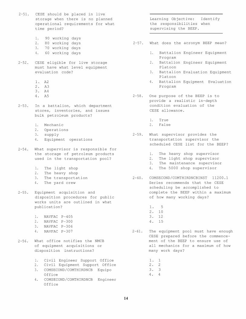
2-51. CESE should be placed in live
2-52.
2-53.
2-54.
2-55.
2-56.
storage when there is no plannedoperational requirements for whattime period?
1. 90 working days2. 80 working days3. 70 working days4. 60 working days
CESE eligible for live storagemust have what level equipmentevaluation code?
1. A22. A33. A44. A5
In a battalion, which departmentstores, inventories, and issuesbulk petroleum products?
1. Mechanic2. Operations3. supply4. Equipment operations
What supervisor is responsible forthe storage of petroleum productsused in the transportation pool?
1. The light shop2. The heavy shop3. The transportation4. The yard crew
Equipment acquisition anddisposition procedures for publicworks units are outlined in whatpublication?
1. NAVFAC P-4052. NAVFAC P-3003. NAVFAC P-3064. NAVFAC P-307
What office notifies the NMCBof equipment acquisitions ordisposition instructions?
1. Civil Engineer Support Office2. Civil Equipment Support Office3. COMSECOND/COMTHIRDNCB Equipo
Office4. COMSECOND/COMTHIRDNCB Engineer
Office
Learning Objective: Identifythe responsibilities whensupervising the BEEP.
2-57.
2-58.
2-59.
2-60.
2-61.
What does the
1. BattalionProgram
2. BattalionPlatoon
3. BattalionPlatoon
4. BattalionProgram
acronym BEEP mean?
Engineer Equipment
Engineer Equipment
Evaluation Equipment
Equipment Evaluation
One purpose of the BEEP is toprovide a realistic in-depthcondition evaluation of theCESE allowance.
1. True2. False
What supervisor provides thetransportation supervisor thescheduled CESE list for the BEEP?
1. The heavy shop supervisor2. The light shop supervisor3. The maintenance supervisor4. The 5000 shop supervisor
COMSECOND/COMTHIRDNCBINST 11200.1Series recommends that the CESEscheduling be accomplished tocomplete the BEEP within a maximumof how many working days?
1. 52. 103. 124. 15
The equipment pool must have enoughCESE prepared before the commence-ment of the BEEP to ensure use ofall mechanics for a maximum of howmany work days?
1. 12. 23. 34. 4
14

2-62. The BEEP assignment list isgenerated by what person?
1. Battalion operations chief2. Battalion operations officer3. Alfa company commander4. Alfa company operations chief
2-63. Which of the following representat-ives conduct the counterpartsmeeting before the commencementof the BEEP?
1. NAVFACENGCOM2. COMSECOND/CCMTHIRDNCB3. CESO4. NAVSUPCOM
2-64. The tracking of the status andlocation of all CESE and EquipmentEvaluation Inspection Guides isthe responsibility of what person?
1. The yard boss2. The collateral equipage
custodian3. The transportation supervisor4. The EO inspectors
2-65. During the BEEP, what actionenhances the control of equip-ment and paper work?
1. Enforcing communication2. Longer work hours3. Securing of liberty4. Enforcing Navy Regulations
2-66. After the EO inspectors havecompleted the procedures outlinedon the Equipment Inspection Guide,the CESE is taken to what location?
1. Mechanic shop2. Collateral equipage3. CESE ready line4. CESE testing area
2-67. What person issues equipment codesfor CESE inspected by the EOs?
2-68. The EO inspections must becompleted no later than howmany days before the plannedBEEP completion date?
1. 12. 23. 44. 5
2-69. What supervisor determines whatrepair can be performed on CESEbased on the work force?
1. The transportation supervisor2. The shop supervisor3. The maintenance supervisor4. The operations supervisor
2-70. The maintenance supervisors reviewall the Equipment EvaluationInspection Guides and approve whatcodes for each CESE?
1. Equipment Codes (EC)2. Equipment Condition Codes3. Equipment Acceptance Codes4. Equipment Cost Codes
2-71. Representatives from what commandapproves all BEEP EquipmentEvaluation Inspection Guides?
1. NAVFACENGCOM2. CESO3. NAVSUPCOM4. COMSECOND/COMTHIRDNCB
Learning Objective: Identifythe responsibilities of theLicense Examiner.
2-72. A properly administered licenseprogram ensures only thoroughlytrained personnel are licensed.
1. True2. False
1. The Alfa operations chief2. The EO inspectors3. The transportation chief4. The yard boss
15

2-73. The license examiner must beappointed by letter by whatperson?
1. The company commander2. The operations officer3. A COMSECOND/COMTHIRDNCB
representative4. The commanding officer
2-74. Which of the following is NOT arequired publication for thelibrary that the license examinermust maintain?
2-75. The maintenance procedures for thefiles on licensed operators mustcomply with the provisions of whatlegal document?
1. The Privacy Act of 19742. The Privacy Act of 19723. The Privacy Act of 19774. The Privacy Act of 1992
1. OPNAVINST 11240.16A2. NAVFAC P-3063. NAVFAC P-4044. NAVFAC P-405
16

ASSIGNMENT 3
Textbook Assignment: “Transportation Supervisor,” and “Air Detachment Equipment Supervisor”pages 1-38 through 2-16.
3-5.Learning Objective: (continued)Identify the responsibilities ofa license examiner.
3-1. What form is used to apply fora material-handling equipmentlicense?
1. NAVFAC 11240/10 3-6.2. NAVFAC 11240/23. NAVFAC 11240/134. NAVFAC 11240/9
3-2. License application forms arecompleted by the applicants andmust be signed by what person?
1. Commanding officer2. Project supervisor 3-7.3. Company chief4. Transportation supervisor
3-3. What publication states militarypersonnel may operate government-owned vehicles under 10,000 poundsGVW without a government license?
1. NAVFAC P-306 3-8.2. NAVFAC P-3003. NAVFAC P-3074. NAVFAC P-404
3-4. The SF-47 is retained in anapplicant’s license file andis replaced with a new one atwhat time? 3-9.
1. Once a year2. When the license is renewed3. When the license is lost4. Every two years
The license examiner does NOT givea performance qualification testfor what type of equipment?
A license examiner should havea minimum of how many writtenexaminations for each type ofequipment?
1. One2. Two3. Three4. Four
Sample written tests forconstruction and weight-handlingequipment are contained in whatpublication?
1. NAVFAC P-3002. NAVFAC P-4053. NAVFAC P-3064. NAVFAC P-307
1. Dozers2. Rock drills3. Graders4. Cranes
What manual contains sampleMHE test questions?
1. NAVFAC P-3072. NAVFAC P-3003. DODINST 4145.19-R-14. DODINST 4160.21M
Which of the following states doesNOT require a valid state driver’slicense in addition to the OF-346to operate government-ownedvehicles off base?
1. Florida2. Nebraska3. Alaska4. Vermont
17

3-10. Which, if any, of the followinginformation can be derived froman OF-346 with the number 133-001?
1. It belongs to the COof NMCB-133
2. It is the first licenseissued by NMCB-133
3. It is the one hundredthirty-third licenseissued by NMCB-1
4. None of the above
3-11. The license examiner issuesan OF-346 on 10 Jan 93 to anindividual with a birth date of12 Jun 70. Unless renewed, thelicense expires on what date?
1. 10 Jan 962. 10 Jan 953. 12 Jun 964. 12 Jun 95
3-12. Typical notations, such as JD670,D7 Cat, are found in what blockon the NAVFAC 11260/2?
1. Equipment type2. Size and capacity3. Attachment4. Type of control
3-13. License renewal actions shouldstart a maximum of how many daysbefore the expiration date?
1. 902. 603. 454. 30
3-14. Under what condition is agovernment operator licenseautomatically extended?
1. While assigned to NCTCfor training
2. While traveling underPCS orders
3. While deployed withan air detachment
4. While assigned to acombat zone
3-15. By power of authority, anoperator’s license can be revokedby which of the following people?
1. Equipment officer2. Maintenance supervisor3. Transportation chief4. License examiner
3-16. In a battalion, what officerconducts traffic court?
1. The legal officer2. The commanding officer3. The equipment officer4. The executive officer
3-17. When an operator’s license isrevoked, the license examinermakes a notation of the daterevoked on what form?
1. NAVFAC 11260/42. NAVFAC 11260/33. NAVFAC 11260/24. NAVFAC 11260/1
3-18. The personnel office is responsiblefor including the license examinerin the check-in or check-outprocess of personnel in a command.
1. True2. False
3-19. Poor equipment operating practicescause accidents and equipmentbreakdowns. To reduce theseproblems, a license examiner canestablish what type of program?
1. Security2. Maintenance3. Safety4. Training
3-20. A training license expiration dateshould not exceed a maximum of howmany days from the date of issue?
1. 152. 203. 254. 30
18

3-21. Mishap investigation guidelines arepresented in which of the followingmanuals?
1. OPNAVINST 11240.16 series2. OPNAV P09B2-1053. OPNAVINST 5102.14. COMSECOND/COMTHIRDNCBINST
4400.3
3-22. A NAVGRAM is required for a mishapthat results in damage that totalshow many dollars?
1. $25002. $20003. $15004. $1000
3-23. In an NMCB, what person shouldcheck the route before moving anoversize load on a public highway?
1. The driver2. The yard boss3. The roadmaster4. The dispatcher
Learning Objective: Recognizethe responsibilities of the airdetachment equipment supervisor.
3-24. After notification, the airdetachment should be capableof deploying within a maximumof how many hours?
1. 122. 243. 484. 72
3-25. The air detachment must be self-sufficient for a maximum of howmany days?
1. 102. 153. 254. 30
3-26. What person is responsible for thedaily management of assigned CESEto the air detachment?
1. Officer in charge (OIC)2. Assistance officer in charge
(AOIC)3. Senior Alfa company rating4. Air det operations chief
3-27. When assigning personnel to theair det, the battalion operationsdepartment uses the guidelinespresented in what manual?
1. NCF embarkation manual2. NCF mobilization planning
manual3. MAC pamphlet airlift planners
manual4. NCF troop movement manual
3-28. The PM/cost control clerk isassigned to which air detachmentplatoon?
1. Support2. Equipment3. Construction4. Maintenance
3-29. Equipment platoon administrationreadiness is the process of storingoffice supplies and forms toprovide a minimum of how many dayssupport?
1. 152. 203. 254. 30
3-30. Which ofrequired
the following forms is NOTto be stored for support
of
1.2.3.4.
equipment platoon readiness?
NAVFAC 9-11260/4NAVFAC 9-11240/13NAVFAC 6-11200/45NAVFAC 11200/41
Learning Objective: Recognizethe Table of Allowance (TOA) usedin the NCF.
19

3-31. The TOA outfits the NMCB withtools and equipment to performconstruction operations undercontingency conditions for aminimum of how many days?
1. 902. 453. 304. 15
3-32. What command is responsiblefor maintaining the NCF TOAs?
1. CESO2. CESOC3. CED4. COMSECOND/COMTHIRDNCB
3-33. The NCF TOA Is divided into threeechelons. What echelon isdesignated for the air det?
1. TA212. TA313. TA414. TA51
3-34. What is the kit number designatorfor lubrication equipment andaccessories?
1. 800132. 800313. 800574. 80107
3-35. When requesting Mod 96, Mod 98, andPOL products, the lead mechaniccoordinates the request with whatperson?
1. The heavy shop supervisor2. The light shop supervisor3. The maintenance supervisor4. The 5000 shop supervisor
3-36. During the 48 hour mount-out,the requested kits and suppliesare staged at what location?
3-37.
3-38.
3-39.
3-40.
3-41.
Learning Objective: Recognize theresponsibilities when identifyingand preparing CESE for the airdetachment.
The air det CESE allowance fora deployment site is containedin what listing?
1. TAB A2. TA413. TAB B4. TA31
The prioritizing of CESE, supplies,and POL products allows what officeto prepare load plans?
1. Equipment2. supply3. Embarkation4. Dispatch
The CESE and cargo that are placedinto a configuration for eachaircraft is known by what term?
1. Cargo load2. Chalk3. Plane load4. Staged load
Special handling data isdocumented on what form?
1. DD Form 1387-22. DD Form 1348-13. DD Form 13424. DD Form 2133
Who directs the operationsof the MOCC?
1. Equipment officer2. Supply officer3. Executive officer4. Embarkation officer
1. Alfa company yard2. Battalion grinder3. Battalion spaces4. Marshaling area
20

3-42. During a mount-out, what areaserves as a coordinating center forall companies and staff personnel?
1. Alfa company2. Quarterdeck3. Marshaling yard4. MOCC
3-43. Embarking CESE on aircraft requiresfollowing the special loadingprocedures that are outlined inwhat manual?
1. 3120.1 series2. 11200.1 series3. P-4044. P-300
3-44. During the mount-out, what membersare responsible for knowing thelocation of the bolts, nuts, andparts for disassembled equipment?
1. Mechanic shop2. Equipment platoon3. Support platoon4. Transportation yard crew
3-45. After Alfa company is completedwith a piece of CESE, what locationdoes the dispatcher notify that theCESE is ready to be transferred?
1. Quarterdeck2. Operations3. MOCC4. Air operations
Learning Objective: Recognize theweighing and marking procedures,and’ shoring used in the NCF.
3-46. When computing the center ofbalance (C/B) of a piece of CESE,you should perform what step first?
1. Establish the distanceto the front axle
2. Establish the distanceto the trunnion
3. Compute the weight ofthe front axle
4. Establish the referencedatum line
3-47. In the weighing and markingprocess, at what step is thevehicle placed on portable scales?
1. When computing for D12. When computing for FAW,
IAW,RAW3. When computing for D24. When computing for D3
3-48. The RAW for a vehicle with tandemaxles is the total weight of whattwo weights added together?
1. FAW + IAW2. FAW + RAW3. IAW + RAW4. GVW + RAW
3-49. To locate the C/B of a vehicle,you measure from what location?
1. From D12. From D23. From D34. From RDL
3-50. What letters are written on thehorizontal portion of the tapeused to denote the C/B of avehicle?
1. GVW2. RDL3. FAW4. RAW
3-51. What type of shoring is requiredfor track equipment?
1. Parking2. Sleeper3. Approach4. Roller
3-52. What type of shoring is usedfor rollers?
1. Parking2. Approach3. Sleeper4. Roller
21

3-53.
3-54.
3-55.
3-56.
3-57.
What type of shoring is requiredfor long vehicles such as low-boytrailers?
1. Parking2. Approach3. Sleeper4. Roller
What shoring is used to preventvehicles with soft tires frombouncing inside the aircraft?
1. Parking2. Approach3. Sleeper4. Roller
Learning Objective: Recognizethe procedures used whenpalletizing cargo in the NCF.
The surface structure of the 463Lis made of a corrosion resistantaluminum. The core is made of whattype of material?
1. Plywood2. Hardwood3. Dogwood4. Softwood
To prolong the life of a 463Lpallet, you should ensure loadweight placed on the pallet notexceed what maximum weight?
1. 8,000 pounds2. 7.500 pounds3. 7,000 pounds4. 6,500 pounds
The top net of the pallet netsis identified by what color?
1. Blue2. Green3. Yellow4. Brown
3-58.
3-59.
3-60.
3-61.
3-62.
Aisleways must be built on palletsthat are to be loaded on a C-130aircraft in what positions?
1. One or two2. Three or four3. Five or six4. Seven or eight
Technical publications requireforklift tines be what minimumlength?
1. 36 inches2. 48 inches3. 60 inches4. 72 inches
What piece of equipment in theNCF TOA has a set of roller tinefork extensions assigned as anattachment?
1. R/T forklift2. 4K forklift3. 6K forklift4. 12K Lift King forklift
Learning Objective: Recognizethe collateral equipage, siteselection, and site arrivalactivities of the air detachment.
Proper management of the air detcollateral equipage programenhances your equipment managementprogram for the air det.
1. True2. False
What environmental factor must notbe overlooked when considering asite for the equipment pool?
1. Drainage2. Type of soil3. Amount of vegetation4. Amount of trees
22

3-63. When the air det embarks byairlift, what number designateshow members are scheduled todepart?
1. The ticket number2. The aircraft number3. The chalk number4. The seat number
3-64. What group normally remains at theairfield until all scheduled chalksarrive at the mission site?
1. Arrival Air Force Control Group2. Airlift Arrival Control Group3. Arrival Airlift Combat Group4. Arrival Airlift Control Group
3-65. What platoon has theresponsibilities of transportingboth cargo and personnel from theairfield to the mission site?
1. Equipment2. Support3. Transport4. Construction
3-66. What platoon has the keyresponsibility for camp setup?
1. Equipment2. Support3. Construction4. Operations
Learning Objective: Recognizethe responsibilities of theequipment platoon operations.
3-67. For control and accountability,what is the best dispatchassignment for air det assignedCESE?
1. Class A2. Class B3. Class C4. Class D
3-68. What person is responsible forequipment-related operations ofthe air det?
1. The support platoon supervisor2. The construction platoon
supervisor3. The equipment platoon
supervisor4. The assistant officer in charge
3-69. During the first few days of an airdet operations, what is one of themost important pieces of CESE?
1. The roller2. The grader3. The generator4. The forklift
3-70. What platoon has the responsibilityto check and fill water buffalosand make daily dump runs?
1. Support2. Construction3. Equipment4. Engineer
3-71. Fuel drums and POL products mustbe stored what minimum number offeet away from any structure?
1. 502. 453. 304. 25
3-72. What supervisor should direct theoperations of the maintenance fieldcrew?
1. Support platoon supervisor2. Air det maintenance supervisor3. Construction platoon supervisor4. Air det engineer supervisor
3-73. When performing maintenance onair det CESE, you are requiredto document which of the followingitems?
1. Repair parts used2. Lube oils used3. Man-hours expended4. All of the above
23

3-74. Guidelines for the air det 3-75. The success of the air det missionmaintenance program are outlined is primary and should always bein what instruction? attained even at the cost of
destroying CESE.1. COMSECOND/COMTHIRDNCBINST
11200.1 series 1. True2. COMSECOND/COMTHIRDNCBINST 2. False
1500.22 series3. COMSECOND/COMTHIRDNCBINST
4400.3 series4. COMSECOND/COMTHIRDNCBINST
11200.11 series
24

ASSIGNMENT 4
Textbook Assignment: “Air Detachment Equipment Supervisor,” “Crane Crew Supervisor,” and“Projects Supervisor,” pages 2-16 through 4-11.
4-5. What governmental agency may
Learning Objective: Recognizerequire a de-bugging steam wash
the air det responsibilitiesbe conducted on all CESE?
for projects, mount-out, andretrograde operations.
1. The Department of Environmentalprotection
2. The Department of Motor
4-1. What is the primary functionof the construction platoon?
1. To perform equipment operations2. To perform camp operations3. To perform construction
operations
4. To perform communicationoperations
4-2. The tailoring of ratings assignedto the air det is dependent uponthe extent and variety of tasking.
1. True2. False
4-3. What person is responsible fordeveloping a productive method forwashing CESE for the mount-out?
1. Support platoon supervisor2. Air det operations chief3. Equipment platoon supevisor4. Air det embarkation officer
4-4. CESE preparation is a time-consuming event that must beproperly planned in order tomeet the deadline for the jointinspection.
1. True2. False
4-6.
4-7.
4-8.
Vehicles
3. The Department of Health andWelfare
4. The Department of Agriculture
What does the acronym DACG mean?
1. Dependent Airlift Crew Group2. Deployment Airlift Construction
Group3. Departure Airlift Construction
Group4. Departure Airlift Control Group
What term identifies the period oftime in which items are inventoriedreordered, cleaned, and turned in?
1. BEEP2. Mount in
3. Retrograde4. Return grade
The final condition of CESE andthe positive accountability ofcollateral equipage and of toolkits determines your final gradein the successful management ofair det CESE?
1. True2. False
Learning Objective: Recognizethe responsibilities for theselection and training of cranecrews in the NCF.
25

4-9. At least what percentage of craneaccidents results from operatorinattention, poor judgment,overconfidence, and/or excessivespeed?
1. 70%2. 75%3. 80%4. 85%
4-10. Which of the following publicationsdoes NOT contain outline standardsfor weight-handling equipment?
1. NAVFAC P-3072. NAVFAC P-4043. NAVFAC P-4054. NAVFAC P-306
4-11. Which of the following supervisorsmust be designated in writing bythe commanding officer?
1. Transportation2. Crane crew3. Projects4. Quarry
4-12. In an NMCB, at what time shouldthe crane crew be selected?
1. At the beginning ofthe deployment
2. At the beginning ofthe home-port period
3. At the end of thehome-port period
4. During the BEEP
4-13. Crane operators assigned tothe crane crew should havewhat characteristics?
1. Maturity and experience2. Experience and personality3. Maturity and education4. Education and personality
4-14. Crane operators must meet theminimum physical examinationrequirements as established bywhat NAVFAC publication?
1. P-4152. P-4043. P-3064. P-315
4-15. Before receiving a license tooperate a crane, an operator mustattend a minimum of how many hoursof formal classroom training?
1. 82. 243. 324. 40
4-16. What person in an NMCB has thedirect responsibility for testingcrane operators?
1. Crane test director2. Crane crew leader3. Certified crane supervisor4. Crane certifying officer
4-17. What person in an NMCB designatesin writing the crane test mechanic?
1. Commanding officer2. Operations officer3. Crane certifying officer4. Crane test director
Learning Objective: Recognizethe procedures for performingthe BEEP of cranes.
4-18. The weight testing of cranes isa time-consuming event and shouldbe completed before the end of theBEEP.
1. True2. False
26

4-19. Which of the following personnelhave the responsibility ofperforming the “before” “during,”and “after” inspection of thecrane?
1. Crane certifying officer2. Crane test operator3. Crane test mechanic4. Crane test rigger
4-20. When transporting a crane on theopen road, you must avoid any powersource by at least what distance?
1. 4 feet2. 10 feet3. 15 feet4. 20 feet
4-21. Which of the following personnelhave the responsibility forcompleting the crane liftchecklist?
1. Crane certifying officer2. Crane crew supervisor3. Crane crew rigger4. Crane crew operator
4-22. What is the minimum requirementsfor retaining ODCLs?
1. ODCLs from the past 90 daysof operations and ODCLs ofthe current month
2. ODCLs from the past 60 daysof operations and ODCLs ofthe current month
3. ODCLs from the previous monthof operations and ODCLs ofthe current month
4. ODCLs of the current monthof operation
4-23. More than two broken wires in onelay in sections beyond the endconnection is the condition forreplacing what section of wirerope?
1. Wire rope connectedto a wedge socket
2. Boom pendant ropes3. Boom hoist ropes4. Wire rope connected
to a winch
4-24. The use of a wedge socket developsonly what percentage of thebreaking strength of the wire rope?
1. 90%2. 80%3. 70%4. 60%
4-25. When should the crane hook blockbe magna-fluxed?
1. After 5 years of service2. After the crane has been
released from deadline3. After any repairs performed
on the hook block4. Every fifth certification
Learning Objective: Recognizethe test procedures performedwhen weight-testing cranes.
4-26. A mobile crane is weight-testedat what percentage of the ratedcapacity of the crane?
1. 100%2. 110%3. 115%4. 125%
4-27. When lifting a load that exceeds75 percent of a crane’s ratedcapacity, you should determine theoperating radius in what manner?
1. By reading the boom angleindicator
2. By actually measuring theoperating radius
3. By watching the boom pendantangle
4. By reading the load chart
4-28. You are assigned to weight testa mobile crane. What is the testweight for a mobile crane with arated capacity of 72,300 pounds?
1. 65,727 pounds2. 79,530 pounds3. 82,159 pounds4. 90,375 pounds
27

4-29. What is the safe working loadof a 3/4-inch hoist wire rope?
1. 4.5 tons2. 6.0 tons3. 9.7 tons4. 10.4 tons
4-30. What is the breaking strengthof a 3/4-inch hoist wire rope?
1. 22.5 tons2. 30.0 tons3. 48.5 tons4. 52.0 tons
4-31. What is the breaking strength ofa 3/4-inch wire rope rigged witha wedge socket?
1. 36.4 tons2. 34.0 tons3. 21.0 tons4. 15.8 tons
4-32. What is the safety factor of a3/4-inch wire rope used as ropethat winds on drums or passeson sheaves?
1. 4.50 tons2. 6.00 tons3. 9.70 tons4. 10.4 tons
4-33. What is the test weight for a3/4-inch wire rope rigged on amobile crane?
1. 9,900 pounds2. 13,200 pounds3. 21,340 pounds4. 22,880 pounds
4-34. What percentage of crane capacityis lost when the crane has a shortboom at maximum radius and is3 degrees out of level?
1. 30%2. 20%3. 15%4. 10%
4-35.
4-36.
4-37.
4-38.
4-39.
When conducting a maximum loadtest, you hold the load clear ofthe ground without the boom andload hoist pawls engaged for whattime period?
1. 5 minutes2. 10 minutes3. 15 minutes4. 20 minutes
When conducting a dynamic test ofthe auxiliary hoist, you must waitwhat length of time after raisingand lowering the test load beforecontinuing the test?
1. 20 minutes2. 15 minutes3. 10 minutes4. 5 minutes
Cranes rigged for clamshell,dragline, or pile-drivingoperations should be weight-testedaccording to what factor?
1. The maximum capacityof the crane
2. The minimum capacityof the crane
3. The safe working load forthe size of wire rope used
4. The safe working load onthe load charts
Retesting of the crane is requiredwhen changing from clamshell todragline.
1. True2. False
At which of the following locationsis the certification of load testand condition inspection filed?
1. Equipment history jacket2. Unit safety office3. Protective container on
the crane4. All of the above
28

4-40. What is the most critical portionof the operation of a crane?
1. Moving the crane2. Setting up for a lift3. Rotating the crane4. Rigging for a lift
4-41. The rated capacities of mobilecranes are based on what factors?
1. Strength and sensibility2. Strength and mobility3. Strength and desirability4. Strength and stability
4-42. In an NMCB, which of the followingpersonnel is NOT required to attendthe biweekly crane operation andsafety meetings?
1. Alfa company commander2. Crane test director3. Battalion safety chief4. Crane supervisor and operator
Learning Objective: Recognizethe NCF wire rope sling andrigging hardware program.
4-43. What person is responsible for theturnover of all slings and rigginghardware during the BEEP?
1. Crane test operator2. Crane certifying officer3. Crane crew rigger4. Crane crew supervisor
4-44. The factor of safety for wirerope slings is what ratio?
1. 5.0 to 12. 3.5 to 13. 3.0 to 14. 4.0 to 1
4-45. The total weight of a load carriedby a single-leg sling at 90 degreesis what type of sling?
4-46. The sling angle for a two-leg slingis at 30 degrees hoisting a 1,000-pound object. What total stressweight is each leg hoisting?
1. 500 pounds2. 750 pounds3. 1,000 pounds4. 1,500 pounds
4-47. If a thimble is not used in an eyeof a wire rope, what percentage ofefficiency of the connection islost?
1. 5%2. 10%3. 15%4. 20%
4-48. When properly fabricated, which ofthe following eye splices developsalmost 100 percent of the cataloguebreaking strength of the wire rope?
1. Flemish eye and serving2. Flemish eye and pressed
metal sleeve3. Tucked eye and serving4. Fold back eye and pressed
metal sleeve
4-49. It is highly recommended that whateye splice never be used foroverhead hoisting operations?
1. Flemish eye and serving2. Tucked eye and serving3. Fold back eye and pressed
metal sleeve4. Tucked eye and pressed
metal sleeve
4-50. What person is responsible forestablishing and maintaining a cardfile system containing records ofeach sling in the unit’s inventory?
1. Crane test director2. Crane crew rigger3. Crane crew mechanic4. Crane crew supervisor
1. Bridle hitch2. Choker hitch3. Double-vertical hitch4. Single-vertical hitch
29

4-51.
4-52.
4-53.
4-54.
4-55.
4-56.
A sling should be maintained on thecrane at the end of each workday.
1. True2. False
Which of the following number ofdesignators does NOT identify anNCF TOA slings and rigging gearkit?
1. 801042. 840033. 840044. 80056
To avoid confusion and doubt, youmay downgrade a sling to a lowercapacity.
1. True2. False
What kit in the NCF TOA containsthe tools and equipment necessaryto fabricate 3/8-inch through5/8-inch sizes of wire rope slings?
1. 801042. 801073. 800924. 84004
At what periodic intervals shoulda visual inspection of all wirerope slings and rigging gear beperformed?
1. Every 30 days2. Every 60 days3. Every 75 days4. Every 90 days
The recommended COMSECOND/COMTHIRDNCBINST wire rope lubricantis composed of what mixture?
1. 70% diesel to 30% used oil2. 70% diesel to 30% new oil3. 70% new oil to 30% gas4. 70% new oil to 30% diesel
4-57. What action is required whenrigging gear becomes defective?
1. Downgrade the capacity2. Survey it through supply3. Destroy it by cutting it up4. Store it in the rigging loft
Learning Objective: Recognizethe responsibilities of the pro-ject supervisor and the conceptsof construction used in an NMCB.
4-58. In an NMCB, what person has directresponsibility for the successfulcompletion of all constructionprojects?
1. Commanding officer2. Operations officer3. Operations chief4. Project supervisor
4-59. In an NMCB, what officer has thedirect supervisory authority overthe utilization of the battalion’sconstruction resources?
1. Executive officer2. Supply officer3. Embarkation officer4. Operations officer
4-60. Within the Alfa companyorganization, what person isresponsible to A-6 for allprime and sub projects?
1. A-52. A-43. A-34. A-32
4-61. In an NMCB, what person appointsproject supervisors for assignedconstruction projects?
1. Company commander2. Operations officer3. Operations chief4. Projects chief
30

4-62. What person determines theorganizational concept ofconstruction used in an NMCB?
1. CO and S-32. NAVFACENGCOM3. COMSECOND/COMTHIRDNCB4. Naval Construction Regiment
4-63. What is the most common construc-tion concept used in the NCF?
1. Project manager/resourcemanager
2. Prime contractor/lead company3. Self-sufficient unit/detail4. Prime company/lead contractor
4-64. What NAVFAC publication outlinesthe concepts of construction usedin the NCF?
1. NAVFAC P-4052. NAVFAC P-4043. NAVFAC P-3204. NAVFAC P-315
4-65. At what step of deployment planningdoes the battalion receivepreliminary tasking and beginmonitoring the efforts of theon-site battalion?
1. Initial2. Detailed3. Follow on4. Follow-up
4-66. At what planning step are personnelassigned to details, companies, andstaff billets?
1. Detailed2. Follow-up3. Initial4. Follow-on
4-67. What element assists companies anddetails with the planning effortand coordinates the detail analysisof project requirements?
4-68. What areas are inspected duringthe first of the three phases ofa readiness-to-deploy inspection?
1. Battalion organization andtraining plans
2. CESE management plans3. Construction project plans4. Execution plans
Learning Objective: Recognizethe steps performed to computeearthwork volumes.
4-69. Mistakes made in P&E can bedetrimental to the successfulcompletion of a constructionproject.
1. True2. False
4-70. What total number of cubic feetequals 1 cubic yard?
1. 32. 93. 274. 36
4-71. When calculating estimates fromconstruction prints, you mustremember that cuts are measuredin what state?
1. Inplace cubic yards2. Compacted cubic yards3. Loose cubic yards4. Swell cubic yards
4-72. In road construction, what is thename of the slope that extends fromthe outside of the shoulder to thebottom of the ditch?
1. Foreslope2. Sideslope3. Backslope4. Frontslope
1. Material liaison office2. Quality control element3. Material construction control4. Quality construction element
31

4-73. When computing the area of a crosssection, you perform what stepfirst?
1. Compute the slope ratio2. Break the section down
into geometric figures3. Compute distance between
stations4. Compute elevation of the
final grade
4-74. What NAVPAC publication containsequipment production rates?
4-75. In a project package, on whatdocument is the equipmentrequirements to support eachconstruction activity documented?
1. MAS sheet2. CAS sheet3. MTO4. BM
1. NAVFAC P-4042. NAVFAC P-3003. NAVFAC P-3064. NAVFAC P-405
32

ASSIGNMENT 5
Textbook Assignment: “Quarry Supervisor,” “Crusher Supervisor,” “Concrete Batch PlantSupervisor,” and “Asphalt Plant Supervisor,” pages 5-1 through 8-10.
Learning Objective: Recognizethe classifications of pits andquarries and the types ofmaterial obtained from them.
5-1. In an NMCB, what company isresponsible for the managementof pit and quarry operations?
1. Alfa2. Bravo3. Charlie4. Headquarters
5-2. Pits and quarries are classifiedbased on which of the followingfactors?
1. Type of material containedwithin
2. Method used to excavate thematerial contained within
3. Method used to process thematerial taken from
4. Each of the above
5-3. Which of the following is NOTa primary material obtained froma quarry?
1. Granite2. Slag3. Gneiss4. Quartize
5-4. The crust of the earth consistsof rock deposits geologists haveclassified into what three groups?
1. Sedimentary, igneous,and shale
2. Sedimentary, metamorphic,and alluvial
3. Igneous, metamorphic,and sedimentary
4. Igneous, silica, and brick
5-5. The hardness of a rock isclassified according to theresistance the rock has tocrushing.
1. True2. False
5-6. Aggregates usedshould be ratedhardness range?
in constructionwithin what
1. Between 1 to 22. Between 2 to 43. Between 5 to 74. Between 8 to 10
5-7. What term identifies the rangeand distribution of particle sizespresent in, or can be obtainedfrom, a deposit?
1. Sieve analysis2. Material fines3. Breakdown analysis4. Gradation
5-8. What type of quarry materialis not suitable for concreteaggregate?
1.2.3.4.
5-9. The
GraniteFelsite-RhyoliteBasaltGabbro-Diorite
portion of a soil sampleretained on the No. 200 sieve isconsidered what type of aggregate?
1. Coarse2. Medium3. Small4. Fine
33

5-10.
5-11.
5-12.
5-13.
5-14.
Which of the following factorsaffect the compaction of soil?
1. Material gradation2. Moisture content3. Compaction effort4. All of the above
Optimum moisture content isthe amount of water in the soilrequired to obtain maximumdensity.
1. True2. False
Learning Objective: Recognizesite preparation procedures andthe operational processes of apit or quarry.
What should you check beforeburning brush on a proposed pitor quarry site?
1. Weather2. Type of fire extinguisher3. Requirement for a smoke permit4. Requirement for a burn permit
Overburden should be kept clearedat least how far back from the topof the face of a quarry?
1. 50 feet2. 40 feet3. 25 feet4. 10 feet
What is the maximum grade fora haul road designed for use bytruck operations
1. 5 percent2. 10 percent3. 15 percent4. 20 percent
in a quarry?
5-15.
5-16.
5-17.
5-18.
5-19.
5-20.
A chute loading ramp should beconstructed to support a minimumof how many tons of material?
1. 5 tons2. 10 tons3. 15 tons4. 20 tons
When a pusher-assisted scrapercannot load within 150 feet, youshould use what equipment?
1. An additional scraper2. An extra pusher3. A ripper tractor4. A front-end loader
Which of the following quarriesis a type commonly used by themilitary?
1. Double bench2. Open faced3. Triple bench4. Closed faced
What factor determines the layoutof a quarry where the rockformation is jointed?
1. The method of development2. The depth of overburden3. The direction of rock
formation4. The lay of the strata
In the NCF, what is therecommended bench heightin a quarry?
1. 10 feet2. 15 feet3. 20 feet4. 25 feet
In the NCF, what is therecommended minimum widthof a bench?
1. 40 feet2. 50 feet3. 60 feet4. 70 feet
34

5-21. What person is responsible forensuring operator maintenance isperformed on quarry equipment?
1. Operations chief2. Maintenance supervisor3. Maintenance field crew4. Quarry supervisor
5-22. What NAVFAC publication providesguidelines for wearfacing equip-ment parts?
1. P-4042. P-4333. P-4054. P-300
5-23. Putting off maintenance to satisfyimmediate production demands setsa good precedence and increasesthe life of the equipment.
1. True2. False
5-24. What is the NEC of a qualifiedblaster?
1. 57102. 57093. 57084. 5707
Learning Objective: Recognizethe principles and methods ofcrusher operations.
5-25. What command directs the taskingof crusher operations for an NMCB?
1. NAVFACENGCOM2. NAVCHAPGRU3. COMSECOND/COMTHIRDNCB4. COMNCFNCB
5-26. The classification of a crusherplant is based on what factor?
5-27. What is the function of theheavy-duty apron type of feeder?
1. Feeds material to thesecondary unit
2. Sorts material beforefeeding the secondary unit
3. Feeds material to the primaryunit
4. Sorts material before feedingthe primary unit
5-28. What component of the primary unitprescreens material that isalready down to the desired size?
1. Vibrating screens2. Apron feeder3. Under crusher delivery
conveyer4. Vibrating grizzly
5-29. In a rock crusher, what problemoccurs when two rocks interlockand bridge the jaws open?
1. Blocking2. Bridging3. Choking4. Packing
5-30. What factor determines theproduction setting for a dualroll crusher?
1. The shell combination2. The speed setting3. The spacing between the rolls4. The hydroset control pressure
5-31. The fineness of the product beingproduced by a hydrocone crusher isadjusted by what action?
1. By raising or lowering themantle
2. By adjusting the feed spout3. By controlling the hydroset
pressure4. By adjusting the concave ring
1. Capacity output2. Weight of crusher unit3. Size jaws4. Area displacement
35

5-32. Material from the hydroconecrusher is recirculated to thetop screen by what components?
1. The return conveyer and therevolving elevator wheel
2. The under conveyer and a dropchute
3. The under conveyer and therevolving elevator wheel
4. The return conveyer and acrossover chute
5-33. The desired performance of aspecific screen is obtainedby taking which of the follow-ing actions?
1. Varying the degree ofinclination
2. Varying the frequencyand amplitude of stroke
3. Varying the direction ofthrow
4. All of the above
5-34. Which of the following is NOTa factor that affects theoperational efficiency of aconveyer?
1. Speed2. Length of travel3. Loading4. Incline
5-35. What factor determines thecapacity of a washing andscreening plant?
1. Water pressure2. Speed of the dehydrator3. Percent of sand in the
deposit4. Capacity of the scrubber
Learning Objective: Recognizecrusher supervisor responsi-bilities for developing thelayout and erection of a crusherplant.
5-36. When you are developing a layoutof a plant, special attention mustbe given to creating a logicalflow of material.
1. True2. False
5-37. Which of the following materialscan contaminate open stockpilesof aggregate?
1. Windblown sand2. Fines3. Trash4. All of the above
5-38. When you are building stockpiles,which of the following pieces ofequipment is more efficientbecause it can combine lift withpush to build higher piles?
1. Dozer2. Clamshell3. Loader4. Excavator
5-39. Which of the following physicalcharacteristics should the siteselected for the erection of aplant have?
1. Flat2. Level3. Well compacted4. All of the above
5-40. When torquing bolts and nuts onthe plant, you do so by torquingthe bolt head.
1. True2. False
36

5-41. Of the following basic setups fora 75-tph crushing plant, which oneshould be used when the bulk ofmaterial from a gravel deposit is3 inches in diameter or less?
1. Jaw crusher2. Primary unit only3. Secondary unit only4. Primary and secondary units
together
5-42. The entire quarry and rockproduction operation dependson improper and inadequatemaintenance of equipment.
1. True2. False
Learning Objective: Recognizethe properties of and uses forvarious types of cement that aconcrete batch plant supervisorworks with.
5-43. The chemical reaction betweencement and water that producesconcrete is known by what term?
1. Concrete2. Hydraulics3. Hydration4. Evaporation
5-44. What type of cement requiresless protection from freezingand attains normal 3-day strengthin 1 day?
1. I2. II3. III4. IV
5-45. Aggregates used in concrete occupywhat percentage of the mix byweight?
1. Between 90% to 95%2. Between 70% to 85%3. Between 60% to 75%
5-46. Stockpiles for concrete aggregates
5-47.
5-48.
5-49.
5-50.
should be built up in a coneshape.
1. True2. False
What condition results if theslope inside an overhead chargingbin is less than 50 degrees?
1. Aggregates dischargetoo quickly
2. The bottom aggregatesabsorb too much water
3. Aggregates segregate whendischarged
4. Aggregates combine too thickly
What is the primary function ofthe water used in a concrete mix?
1. It wets the aggregates sothe cement will bind
2. It starts the hardeningprocess (hydration) of thecement
3. It makes the mix workable4. It prevents the cement from
curing too fast
When an air-entraining agent isused at a site, it is added towhat element of a cement mix?
1. The aggregate for the mix2. The concrete granules for
the mix3. The water to be used in the
mix4. The cement to be used in the
mix
Which of the following materialscan be used to retard the set ofa concrete mix?
1. Borax2. Sugar3. Salt4. Each of the above
4. Between 50% to 55%
37

5-51. A total of how many cubic yardsof concrete is required for a pad60 feet in length, by 30 feet inwidth, with a depth of 4 inchesand a waste factor of 10 percent?
1. 24.22. 22.03. 59.44. 65.3
5-52. Batching by volume providesgreater accuracy and avoidsproblems created by the bulkingof damp sand.
1. True2. False
5-53. When mixing concrete in a transitmixer, what is the maximum numberof revolutions of the drum atmixing speed that you should use?
1. 602. 703. 904. 100
5-54. What is the minimum agitatingspeed on a transit mixer?
1. 1 revolution per minute2. 2 revolutions per minute3. 3 revolutions per minute4. 4 revolutions per minute
5-55. Concrete that is kept agitated cangenerally be placed within whatmaximum time period after mixing?
1. 3 1/2 hours2. 2 1/2 hours3. 1 1/2 hours4. 1/2 hour
5-56. On a mobile concrete mixer plant,the sand and aggregate areaccurately proportioned accordingto what measurement(s)
1. By cubic feet of material only2. By cubic yards of material
only3. By weight or by cubic feet4. By weight or by volume
5-57. You are conducting a slump test.Which of the following resultsindicate a poor mix?
1. The concrete mix crumbles2. The concrete mix segregates3. The concrete mix falls apart4. Each of the above
5-58. When working around cement, youshould pay particular attentionto any rash on your skin becausea rash may indicate cementpoisoning.
1. True2. False
Learning Objective: Describe theoperations of an asphalt plant.
5-59. On a batch plant, the size ofa batch varies according to thecapacity of what component?
1. The hopper2. The dryer3. The pugmill4. The screens
5-60. The proper amount of aggregatesfor asphalt mixes is initiallycontrolled by a uniform flow ofthe aggregate through whatcomponent?
1. Cold-feed adjustment2. Hot-feed adjustment3. Cold-bin capacity4. Hot-bin capacity
5-61. The overloading of the screenswith aggregate underscores a needfor control of what factor?
1. Proper dryer control2. Proper weigh-hopper
calibration3. Proper cold feeding4. Proper gradation control
calibration
38

5-62. The grading of an individual coldaggregate is determined by takingwhat action?
1. Matching a sample of aggregatewith a previous marked sample
2. Running a sieve analysis3. Measuring the rate of
aggregate to the fines4. Noting the progressive
thickness of the fines
5-63. Which of the following factorscontrol the time required foraggregate to pass through a dryer?
1. The cylinder speed2. The slope of the cylinder3. The length, arrangements,
and number of flights4. All of the above
5-64. When aggregate particles showsigns of an oily coating afterleaving the dryer, you shouldmake what adjustment?
1. Decrease the amount of fueloil
2. Decrease blower or draft airpressure
3. Increase the amount of fueloil
4. Increase the amount of naturalgas
5-65. What factor controls thetemperature of an asphalt mix?
1. The temperature of the asphalt2. The temperature of the dryer3. The temperature of the
aggregates4. The temperature of the pugmill
5-66. If not kept clean, which of thefollowing components can be aserious cause of air pollutionat an asphalt plant?
5-67. The Jet-Pulse system is used in anasphalt plant as a method to gainwhat result?
1. Production of pulses of heatto keep aggregate hot
2. Production of suction pulsesto control dust
3. Production of a pulse ofpressure within a filter bagto dislodge “dust cake”
4. A method that produces astream of hot asphalt ontoaggregates
5-68. What factors determine the amountof dust from the dust collectorthat can be returned to the plant?
1. Moisture content2. Degree of suspension
efficiency3. Mix specification4. Separate grading of the finish
mix
5-69. In the gradation control unit,which of the following screensis used as a scalping screen?
1. Top screen2. Top intermediate screen3. Bottom intermediate screen4. Bottom screen
5-70. As associated with the gradationcontrol unit, what does the term“carry-over” mean?
1. Larger aggregates aremisdirected to smalleraggregate bins
2. Rejected aggregates are“carried-over” to a dischargechute
3. Smaller aggregates aremisdirected into the largeraggregate bins
4. Improperly heated aggregatesare reheated
1. Screens2. The dryer combustion unit3. The dryer4. The hopper
39

5-71. Bin partitions should have whichof the following properties toprevent intermingling of theaggregates within the hot bins?
1. Be tight fitting2. Be free of holes3. Be of sufficient height4. All of the above
5-72. In a continuous-flow plant, asample of hot aggregate shouldbe obtained from which of thefollowing locations?
1. Scalping screens2. Overflow vents3. Feeder gates4. Dryer
5-73. What function does the verticalslot in the asphalt return lineserve in asphalt heating andcirculation?
1. It breaks the vacuum in theline upon reversing the pump
2. It allows for circulation ofasphalt through the feedingand storage system
3. It prevents oxidation of theasphalt
4. It provides a means ofsampling asphalt
5-74. The temperature of the asphaltcontrols the temperature of anasphalt and aggregate mixture.
1. True2. False
5-75. As part of an asphalt mix design,what is the purpose of the mineralfiller?
1. To increase the weightof intermediate aggregate
2. To decrease the curing timeof the asphalt mix
3. To increase the workabilityof the asphalt mix
4. To fill in the voids of theaggregates
40

ASSIGNMENT 6
Textbook Assignment: “Asphalt Plant Supervisor,” and “Well Drilling Superisor,” pages 8-11through 9-17.
Learning Objective: (continued):Recognize the operations of anasphalt plant.
6-1. Using tabledistributorfor asphalt
1. Between2. Between3. Between4. Between
8-1, what is thespraying temperatureemulsion SS-1h?
50°F-140°F75°F-130°F110°F-160°F135°F-175°F
6-2. Final metering of mineral fillerto a mix is accomplished throughwhat device?
1. A variable speed vane2. A screw feeder3. A belt feeder4. One of the above, depending
on the material being handled
Learning Objective: Recognizethe operational processes ofa batch asphalt plant.
6-3. Which of the following units is adistinguishing feature of a batchasphalt plant?
1. The cold aggregate feedunit
2. The batching unit3. The dryer unit4. The dust collector unit
6-4. From the hot bins, what sizeaggregates are deposited intothe weigh-hopper first?
1. Coarse2. Intermediate3. Fine4. Mineral filler
6-5.
6-6.
6-7.
6-8.
A pugmill’s “live zone” is the netvolume in cubic yards below a lineextending across the top arc ofthe inside body shell radius, withshafts, liners, paddles, and tipsdeducted.
1. True2. False
In a batch asphalt plant, inwhat location do the aggregates,mineral filler, and asphalt getmixed together?
1. Dryer2. Weigh-hopper3. Pugmill4. Asphalt weigh bucket
In what manual can the batchasphalt plant supervisor finddetails on the setup andadjustment of the automaticequipment?
1. NAVFAC SupervisoryInstructions Manual
2. COMSECOND/COMTHIRDNCBINSTEquipment Management Manual
3. Manufacturer operator’s manual4. Alfa company operations manual
Learning Objective: Recognizethe operational processes of acontinuous-flow asphalt plant.
What factor must be known at alltimes in order to maintainconstant asphalt proportioning?
1. The temperature of theaggregate
2. The output temperatureof the dryer
3. The temperature of the hotbins
4. The temperature of the asphalt
41

6-9.
6-10.
6-11.
6-12.
6-13.
What are the characteristics ofthe movement of materials withina continuous-flow plant pugmill?
1 They are confined in themixer chamber
2. They are propelled towarddischarge
3. They are continuously mixedin the mixer chamber
4. They are continuously mixed,weighed, then discharged
What period of time beginswhen all the combined mineralaggregates are in the mixerand ends when the gate is open?
1. The total mixing time2. The wet mixing time3. The dry mixing time4. The shortest mixing time
What period of time starts withthe asphalt application and endswith the opening of the dischargegates?
1. The total mixing time2. The wet mixing time3. The dry mixing time4. The shortest mixing time
What environmental conditionmakes asphalt film harden onthe aggregates?
1. Exposure to air2. Exposure to moisture3. Exposure to heat and air4. Exposure to moisture and air
Which of the following is NOTa part of the automatic controlsystem for a continuous-flowplant?
1. Burner controls2. Mix discharge3. Dryer control4. Mixer and gradation cutoffs
Learning Objective: Recognizethe operational processes ofa drum-mix asphalt plant.
6-14.
6-15.
6-16.
6-17.
6-18.
6-19.
In a drum-mix plant, in whatlocation is aggregate mixedwith the asphalt?
1. In the mix surge silo2. In the hot-mix conveyer3. In the dust collector4. In the dryer
The drum-mix plant gradationcontrol unit proportions allthe aggregate before it entersthe mixing drum.
1. True2. False
What factor is the basis fordetermining the quantity ofasphalt delivered into the drum?
1. The weight of the aggregate2. The gradation of the aggregate3. The drum-mix output
requirement4. The speed of the in-line belt
feeder
What section in a drum-mixerheats and dries the aggregate?
1. Primary2. Intermediate3. Secondary4. Third
What condition creates an oilycoating on the aggregateparticles?
1. Aggregate not heated2. An unbalanced distribution
of asphalt3. A lack of balance in the
burner operation4. Drum-mixer speed is too slow
The drum-mix plant produces abatch-flow of asphalt that canbe temporarily stored in the surgesilo.
1. True2. False
42

Learning Objective: Identifythe properties of bituminoussurfacing materials.
6-20. What is/are the function(s) of theaggregates in a asphalt surface?
1. Transmits the load from thesurface to the subgrade
2. Absorbs the abrasive wearof the traffic
3. Provides a nonskid surface4. All of the above
6-21. Which of the following factorsis required to support the bearingaction on a bituminous wearingsurface?
1. Larger aggregates placedin the mix design
2. Subgrade and base coursemust have adequate thickness,strength, cohesion, andbearing capacity
3. Upgrade the amount of asphaltin the mix
4. Give the mix adequate curingtime
6-22. Which of the following is abituminous surfacing material?
1. Emulsion2. Tar3. Asphalt bitumen4. Each of the above
6-23. A container of bituminous materiallabeled with the symbol AC indi-cates it contains which of thefollowing materials?
1. Asphalt cutback2. Asphalt cement3. Asphalt emulsion4. Anionic-cationic asphalt
6-24. When used with asphalt cement,which of the following distillatesallows for slow curing afterapplication to a roadway?
1. Naphtha2. Kerosene3. Fuel oil4. Gasoline
6-25. Which of the following viscositygrades of an MC asphalt bitumenis considered the most fluid?
1. 30 to 602. 200 to 8003. 800 to 1,0004. 1,000 to 3,000
6-26. When added to asphalt cement,which of the following producesan asphalt emulsion?
1. Water only2. Soap only3. Water and soap4. Kerosene
6-27. What road tar symbol designatesa hot tar?
1. RT 12. RT 23. RT 54. RT 9
Learning Objective: Recognizethe test for identifyingbituminous materials.
6-28. Field identification of bituminousmaterials found stockpiled inunmarked containers is necessaryfor which of the followingreasons?
1. To determine the type andmethod of construction thematerial can be used for
2. To establish safe handlingpractices for the material
3. To determine type and qualityof equipment needed
4. All of the above
43

6-29. Normally, what field test is usedto differentiate between unknownbituminous materials?
1. Heat-odor2. Volubility3. Water-mixing4. Penetration
6-30. When you are performing thevolubility test, what materialwill form a stringy undissolvedmass?
1. Asphalt2. Asphalt cement3. Emulsion4. Tar
6-31. Asphalt cutbacks are fluidat room temperature.
1. True2. False
6-32. What grade of asphalt is indicatedby a field test in which the sharppoint of pencil penetrates theasphalt with difficulty?
1. Hard2. Medium3. Soft4. Medium hard
Learning Objective: Recognizeand compute estimates ofmaterials.
6-33. What is the purpose of a primecoat?
1. Waterproof the surface2. Plug capillary voids3. Coat and bond loose
particles4. All of the above
6-34. If the ROA is not known, what ROAis used in the NCF for planningpurposes?
1. .12. .23. .34. .4
6-35.
6-36.
6-37.
6-38.
6-39.
How many gallons of prime coatis require for a project 2 mileslong, 12 feet wide, waste factorof 5 percent, and a ROA of 0.3gal/sq yd?
1. 4435.2 gal2. 5174.4 gal3. 6336 gal4. 7392 gal
What happens when a tack coatis applied too heavily?
1.
2.
3.
4.
For
Soaks into the surfacematerialThe overlying coarse willnot stick to the surfacecoarseIt will bleed into theoverlying coarseIt will cause the surfacecoarse to crumble
the purpose of planning, whatis the NCF ROA for a tack coat?
1. .102. .153. .204. .25
A total of how many drums of tackcoat material is required for aproject 500 feet long, 50 feetwide, waste factor of 5 percent,and a ROA of .15?
1. 8.25 drums2. 11.79 drums3. 43.74 drums4. 82.54 drums
You are tasked with a singlesurface treatment of a road20 miles long, 12 feet wide, anda waste factor of 10 percent. A100-square/yard test strip showedthat 2 tons of aggregate was used.What is the rate of application ofaggregate in pounds per sq/yd?
1. 102. 203. 304. 40
44

6-40. Using question 6-39, what totalnumber of tons of aggregate isrequired for this task?
1. 1548.82. 2323.23. 3097.64. 3872.2
6-41. Using equation 2, a total of howmany pounds per square inch woulda 4-inch asphalt mat equal?
1. 1462. 1103. 2204. 440
6-42. A total of how many tons ofasphalt is required for a parkinglot 120 feet long, 60 feet wide,2 inches thick, with 5 percentwaste factor?
1. 332. 463. 924. 331
6-43. The required tonnage of hot-mixasphalt for a project is 300 tons.The screed of the paver is set at12 feet, and the depth of asphaltis 2 inches. Estimate the amountof asphalt that can be laid perhour?
1. 34.682. 80.463. 96.554. 102.4
6-44. When using the horn signal system,what does two blasts of the hornmean?
1. Stop2. Go forward3. Turn around4. Back up
6-45. In which underground zone, if any,should a water well be developed?
1. Plant zone2. Saturated3. Aeration4. None
6-46. Which of the following beltsis NOT part of the zone ofaeration?
1. Soil moisture2. Intermediate3. Saturation4. Capillary fringe
6-47. What is the name of the watercontained in the zone of aeration?
1. Subsurface water2. Ground water3. Soil water4. Surface water
6-48. What formation is porous andpermeable and can yield usablequantities of water?
1. Artesian2. Alluvial basin3. Aquifer4. Capillary fringe
6-49. An artesian well is a source offresh water flowing freely froman aquifer in which the waterpressure exceeds atmosphericpressure.
1. True2. False
6-50. Which of the following rockformations is most likely toproduce water in usablequantities?
1. Igneous2. Sedimentary3. Alluvial4. Metamorphic
Learning Objective: Identifyfundamentals of developingsources of ground water.
45

6-51. When nothing is known of the waterresources in a particular area,the existence of water-producingformations can be verified bywhich of the following means?
1. Exploratory drilling2. Inspecting outcrops of rock
formations3. Studying maps and documents4. Each of the above
6-52. A “drilled” well is normallydrilled to a depth of what numberof feet?
1. 1,0002. 1,5003. 2,0004. 2,500
Learning Objective: Recognizethe operation of rotary drilling.
6-53. What type of drilling methodis used in areas where groundformations are loose andunconsolidated?
1. Mud drilling2. Air drilling3. Down-hole-drilling4. Percussion drilling
6-54. During rotary drilling, a rapidyet smooth penetration of thedrill bit is an indication thatthe bit is entering a
1. bed of gravel2. formation of fine sand3. clay formation4. consolidated formation
6-55. Of the crew members operating therotary well-drilling rig, who hasthe responsibility for carryingout the overall drilling program?
6-56. Personnel engaged in well-drillingoperations should observe which ofthe following safety measures?
1. Wear tight fitting clotheswhile working around movingmachinery
2. Wear gloves when handlingwire rope or metal parts
3. Wear safety shoes and hardhats
4. All of the above
6-57. Which component of a kelly-driverotary well-drilling rig isconnected to the top joint of thedrill pipe?
1. The hoisting plug2. The kelly3. The water swivel4. The drill collar
6-58. Which of the following componentsof the kelly-drive rotarywell-drilling rig controls therate of feed to the drilling bit?
1. The kelly drum brake2. The hoist drum3. The drill collar4. The rotating table
6-59. On the kelly-drive rotarywell-drilling rig, what accessoryholds the drill pipe securelyduring joint addition or removal?
1. The drill collar2. The hoisting plug3. The set of slips4. The kelly sub
1. The project supervisor2. The tool pusher3. The driller4. The derrick hand
46

6-60. In the operation of the rotarydrilling rig, what factors worktogether to prevent the walls ofthe drill hole from collapsingwhen the cut material is washedto the surface by a mixture ofmud and water?
1.
2.
3.
4.
The filtering action ofthe coarse material inthe settling pitThe weight and viscosityand the plastering actionof the fluid on the wallof the well holeThe action of suspendedlocal mud in the fluid andthe additional weight of thefluid due to its content ofsuspended clayThe suspension of cuttingsin the settling pit and thespiraling of the fluid againstthe wall of the drill hole
6-61. What is considered the normalquantity of water needed tosupport an 8 hour shift ofrotary well-drilling?
1. 100 to 500 gallons2. 500 to 750 gallons3. 750 to 1,000 gallons4. 1,000 to 4,000 gallons
6-62. What type of drill bit is used fordrilling through a moderately hardsurface formation with a rotaryrig?
1. Pilot2. Roller3. Fishtail4. Three way
6-63. After the well hole has beendrilled the length of the kelly,what accessory is placed to keepthe well from caving in from thesurface?
1. Turntable2. Surface casing3. Drill collar4. Set of slips
6-64. What depth is the top-head driverotary well-drilling rig capableof rotary drilling?
1. 900 feet2. 1,000 feet3. 1,250 feet4. 1,500 feet
6-65. On the ITWD, what is the purposeof the split centralizer?
1. To break and make drillpipe connections
2. To support the drillstring during handling
3. To aid in setting casings4. All of the above
6-66. What material is used to lubricatethe top-head spindle sub threads?
1. Drilling lubricant2. Petroleum jelly3. Pipe dope4. Fish oil
6-67. When performing down-hole-drillingoperations, how is the oil flowchecked?
1.
2.
3.
4.
Inspecting the oil patternon a piece of card board thatis placed under the spindleChecking the amount of oilon the cuttingsPlacing your hand under thehammer and inspecting theamount of oil dischargedDisconnecting the flushinghose and inspecting the amountof oil discharged from thehose
47
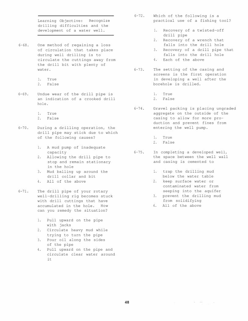
Learning Objective: Recognizedrilling difficulties and thedevelopment of a water well.
6-68. One method of regaining a lossof circulation that takes placeduring well drilling is tocirculate the cuttings away fromthe drill bit with plenty ofwater.
1. True2. False
6-69. Undue wear of the drill pipe isan indication of a crooked drillhole.
1. True2. False
6-70. During a drilling operation, thedrill pipe may stick due to whichof the following causes?
1. A mud pump of inadequatecapacity
2. Allowing the drill pipe tostop and remain stationaryin the hole
3. Mud balling up around thedrill collar and bit
4. All of the above
6-71. The drill pipe of your rotarywell-drilling rig becomes stuckwith drill cuttings that haveaccumulated in the hole. Howcan you remedy the situation?
1. Pull upward on the pipewith jacks
2. Circulate heavy mud whiletrying to turn the pipe
3. Pour oil along the sidesof the pipe
4. Pull upward on the pipe andcirculate clear water aroundit
48
6-72. Which of the following is apractical use of a fishing tool?
1. Recovery of a twisted-offdrill pipe
2. Recovery of a wrench thatfalls into the drill hole
3. Recovery of a drill pipe thatfalls into the drill hole
4. Each of the above
6-73. The setting of the casing andscreens is the first operationin developing a well after theborehole is drilled.
1. True2. False
6-74. Gravel packing is placing ungradedaggregate on the outside of thecasing to allow for more pro-duction and prevent fines fromentering the well pump.
1. True2. False
6-75. In completing a developed well,the space between the well walland casing is cemented to
1. trap the drilling mudbelow the water table
2. keep surface water orcontaminated water fromseeping into the aquifer
3. prevent the drilling mudfrom solidifying
4. All of the above

