nchrp synthesis 354 – inspection and management of … · of bridges with fracture-critical...
TRANSCRIPT
Inspection and Management of Bridges with Fracture-
Critical Details
A Synthesis of Highway Practice
NATIONALCOOPERATIVE HIGHWAYRESEARCH PROGRAMNCHRP
SYNTHESIS 354
TRANSPORTATION RESEARCH BOARD EXECUTIVE COMMITTEE 2005 (Membership as of November 2005)
OFFICERSChair: John R. Njord, Executive Director, Utah DOTVice Chair: Michael D. Meyer, Professor, School of Civil and Environmental Engineering, Georgia Institute of TechnologyExecutive Director: Robert E. Skinner, Jr., Transportation Research Board
MEMBERSMICHAEL W. BEHRENS, Executive Director, Texas DOTALLEN D. BIEHLER, Secretary, Pennsylvania DOTLARRY L. BROWN, SR., Executive Director, Mississippi DOTDEBORAH H. BUTLER, Vice President, Customer Service, Norfolk Southern Corporation and Subsidiaries, Atlanta, GAANNE P. CANBY, President, Surface Transportation Policy Project, Washington, DCJOHN L. CRAIG, Director, Nebraska Department of RoadsDOUGLAS G. DUNCAN, President and CEO, FedEx Freight, Memphis, TNNICHOLAS J. GARBER, Professor of Civil Engineering, University of VirginiaANGELA GITTENS, Vice President, Airport Business Services, HNTB Corporation, Miami, FLGENEVIEVE GIULIANO, Director, Metrans Transportation Center, and Professor, School of Policy, Planning, and Development,
USC, Los AngelesBERNARD S. GROSECLOSE, JR., President and CEO, South Carolina State Ports AuthoritySUSAN HANSON, Landry University Professor of Geography, Graduate School of Geography, Clark UniversityJAMES R. HERTWIG, President, CSX Intermodal, Jacksonville, FLGLORIA JEAN JEFF, Director, Michigan DOTADIB K. KANAFANI, Cahill Professor of Civil Engineering, University of California, Berkeley HERBERT S. LEVINSON, Principal, Herbert S. Levinson Transportation Consultant, New Haven, CTSUE MCNEIL, Professor, Department of Civil and Environmental Engineering, University of DelawareMICHAEL R. MORRIS, Director of Transportation, North Central Texas Council of GovernmentsCAROL A. MURRAY, Commissioner, New Hampshire DOTMICHAEL S. TOWNES, President and CEO, Hampton Roads Transit, Hampton, VAC. MICHAEL WALTON, Ernest H. Cockrell Centennial Chair in Engineering, University of Texas, AustinLINDA S. WATSON, Executive Director, LYNX—Central Florida Regional Transportation Authority
MARION C. BLAKEY, Federal Aviation Administrator, U.S.DOT (ex officio)JOSEPH H. BOARDMAN, Federal Railroad Administrator, U.S.DOT (ex officio)REBECCA M. BREWSTER, President and COO, American Transportation Research Institute, Smyrna, GA (ex officio)GEORGE BUGLIARELLO, Chancellor, Polytechnic University, and Foreign Secretary, National Academy of Engineering (ex officio)J. RICHARD CAPKA, Acting Administrator, Federal Highway Administration, U.S.DOT (ex officio)THOMAS H. COLLINS (Adm., U.S. Coast Guard), Commandant, U.S. Coast Guard (ex officio)JAMES J. EBERHARDT, Chief Scientist, Office of FreedomCAR and Vehicle Technologies, U.S. Department of Energy (ex officio)JACQUELINE GLASSMAN, Deputy Administrator, National Highway Traffic Safety Administration, U.S.DOT (ex officio)EDWARD R. HAMBERGER, President and CEO, Association of American Railroads (ex officio)DAVID B. HORNER, Acting Deputy Administrator, Federal Transit Administration, U.S.DOT (ex officio)JOHN C. HORSLEY, Executive Director, American Association of State Highway and Transportation Officials (ex officio)JOHN E. JAMIAN, Acting Administrator, Maritime Administration, U.S.DOT (ex officio)EDWARD JOHNSON, Director, Applied Science Directorate, National Aeronautics and Space Administration (ex officio) ASHOK G. KAVEESHWAR, Research and Innovative Technology Administrator, U.S.DOT (ex officio) BRIGHAM MCCOWN, Deputy Administrator, Pipeline and Hazardous Materials Safety Administration, U.S.DOT (ex officio)WILLIAM W. MILLAR, President, American Public Transportation Association (ex officio) SUZANNE RUDZINSKI, Director, Transportation and Regional Programs, U.S. Environmental Protection Agency (ex officio)ANNETTE M. SANDBERG, Federal Motor Carrier Safety Administrator, U.S.DOT (ex officio)JEFFREY N. SHANE, Under Secretary for Policy, U.S.DOT (ex officio)CARL A. STROCK (Maj. Gen., U.S. Army), Chief of Engineers and Commanding General, U.S. Army Corps of Engineers (ex officio)
NATIONAL COOPERATIVE HIGHWAY RESEARCH PROGRAM
Transportation Research Board Executive Committee Subcommittee for NCHRPJOHN R. NJORD, Utah DOT (Chair)J. RICHARD CAPKA, Federal Highway Administration JOHN C. HORSLEY, American Association of State Highway
and Transportation Officials
MICHAEL D. MEYER, Georgia Institute of TechnologyROBERT E. SKINNER, JR., Transportation Research BoardMICHAEL S. TOWNES, Hampton Roads Transit, Hampton, VA C. MICHAEL WALTON, University of Texas, Austin
TRANSPORTATION RESEARCH BOARDWASHINGTON, D.C.
2005www.TRB.org
NAT IONAL COOPERAT IVE H IGHWAY RESEARCH PROGRAM
NCHRP SYNTHESIS 354
Research Sponsored by the American Association of State Highway and Transportation Officials in Cooperation with the Federal Highway Administration
SUBJECT AREAS
Bridges, Other Structures, and Hydraulics and Hydrology and Maintenance
Inspection and Management of Bridges with Fracture-
Critical Details
A Synthesis of Highway Practice
ROBERT J. CONNOR
Purdue University
West Lafayette, Indiana
ROBERT DEXTER
University of Minnesota
Minneapolis, Minnesota
and
HUSSAM MAHMOUD
Lehigh University
Bethlehem, Pennsylvania
NATIONAL COOPERATIVE HIGHWAY RESEARCH PROGRAM
Systematic, well-designed research provides the most effectiveapproach to the solution of many problems facing highwayadministrators and engineers. Often, highway problems are of localinterest and can best be studied by highway departmentsindividually or in cooperation with their state universities andothers. However, the accelerating growth of highway transportationdevelops increasingly complex problems of wide interest tohighway authorities. These problems are best studied through acoordinated program of cooperative research.
In recognition of these needs, the highway administrators of theAmerican Association of State Highway and TransportationOfficials initiated in 1962 an objective national highway researchprogram employing modern scientific techniques. This program issupported on a continuing basis by funds from participatingmember states of the Association and it receives the full cooperationand support of the Federal Highway Administration, United StatesDepartment of Transportation.
The Transportation Research Board of the National Academieswas requested by the Association to administer the researchprogram because of the Board’s recognized objectivity andunderstanding of modern research practices. The Board is uniquelysuited for this purpose as it maintains an extensive committeestructure from which authorities on any highway transportationsubject may be drawn; it possesses avenues of communications andcooperation with federal, state, and local governmental agencies,universities, and industry; its relationship to the National ResearchCouncil is an insurance of objectivity; it maintains a full-timeresearch correlation staff of specialists in highway transportationmatters to bring the findings of research directly to those who are ina position to use them.
The program is developed on the basis of research needsidentified by chief administrators of the highway and transportationdepartments and by committees of AASHTO. Each year, specificareas of research needs to be included in the program are proposedto the National Research Council and the Board by the AmericanAssociation of State Highway and Transportation Officials.Research projects to fulfill these needs are defined by the Board, andqualified research agencies are selected from those that havesubmitted proposals. Administration and surveillance of researchcontracts are the responsibilities of the National Research Counciland the Transportation Research Board.
The needs for highway research are many, and the NationalCooperative Highway Research Program can make significantcontributions to the solution of highway transportation problems ofmutual concern to many responsible groups. The program,however, is intended to complement rather than to substitute for orduplicate other highway research programs.
Published reports of the
NATIONAL COOPERATIVE HIGHWAY RESEARCH PROGRAM
are available from:
Transportation Research BoardBusiness Office500 Fifth Street, NWWashington, DC 20001
and can be ordered through the Internet at:
http://www.national-academies.org/trb/bookstore
Printed in the United States of America
NCHRP SYNTHESIS 354
Project 20-5 (Topic 35-08)ISSN 0547-5570ISBN 0-309-09761-4Library of Congress Control No. 2005937608
© Transportation Research Board
Price $27.00
NOTICE
The project that is the subject of this report was a part of the NationalCooperative Highway Research Program conducted by the TransportationResearch Board with the approval of the Governing Board of the NationalResearch Council. Such approval reflects the Governing Board’s judgment thatthe program concerned is of national importance and appropriate with respectto both the purposes and resources of the National Research Council.
The members of the technical committee selected to monitor this project andto review this report were chosen for recognized scholarly competence andwith due consideration for the balance of disciplines appropriate to the project.The opinions and conclusions expressed or implied are those of the researchagency that performed the research, and, while they have been accepted asappropriate by the technical committee, they are not necessarily those of theTransportation Research Board, the National Research Council, the AmericanAssociation of State Highway and Transportation Officials, or the FederalHighway Administration, U.S. Department of Transportation.
Each report is reviewed and accepted for publication by the technicalcommittee according to procedures established and monitored by theTransportation Research Board Executive Committee and the GoverningBoard of the National Research Council.
NOTE: The Transportation Research Board of the National Acade-mies, the National Research Council, the Federal Highway Administra-tion, the American Association of State Highway and Transporta-tion Officials, and the individual states participating in the NationalCooperative Highway Research Program do not endorse products ormanufacturers. Trade or manufacturers’ names appear herein solely because they are considered essential to the object of thisreport.
The National Academy of Sciences is a private, nonprofit, self-perpetuating society of distinguished schol-ars engaged in scientific and engineering research, dedicated to the furtherance of science and technology and to their use for the general welfare. On the authority of the charter granted to it by the Congress in 1863, the Academy has a mandate that requires it to advise the federal government on scientific and techni-cal matters. Dr. Ralph J. Cicerone is president of the National Academy of Sciences.
The National Academy of Engineering was established in 1964, under the charter of the National Acad-emy of Sciences, as a parallel organization of outstanding engineers. It is autonomous in its administration and in the selection of its members, sharing with the National Academy of Sciences the responsibility for advising the federal government. The National Academy of Engineering also sponsors engineering programs aimed at meeting national needs, encourages education and research, and recognizes the superior achieve-ments of engineers. Dr. William A. Wulf is president of the National Academy of Engineering.
The Institute of Medicine was established in 1970 by the National Academy of Sciences to secure the services of eminent members of appropriate professions in the examination of policy matters pertaining to the health of the public. The Institute acts under the responsibility given to the National Academy of Sciences by its congressional charter to be an adviser to the federal government and, on its own initiative, to identify issues of medical care, research, and education. Dr. Harvey V. Fineberg is president of the Institute of Medicine.
The National Research Council was organized by the National Academy of Sciences in 1916 to associate the broad community of science and technology with the Academy’s purposes of furthering knowledge and advising the federal government. Functioning in accordance with general policies determined by the Acad-emy, the Council has become the principal operating agency of both the National Academy of Sciences and the National Academy of Engineering in providing services to the government, the public, and the scientific and engineering communities. The Council is administered jointly by both the Academies and the Institute of Medicine. Dr. Ralph J. Cicerone and Dr. William A. Wulf are chair and vice chair, respectively, of the National Research Council.
The Transportation Research Board is a division of the National Research Council, which serves the National Academy of Sciences and the National Academy of Engineering. The Board’s mission is to promote innovation and progress in transportation through research. In an objective and interdisciplinary setting, the Board facilitates the sharing of information on transportation practice and policy by researchers and practitioners; stimulates research and offers research management services that promote technical excellence; provides expert advice on transportation policy and programs; and disseminates research results broadly and encourages their implementation. The Board’s varied activities annually engage more than 5,000 engineers, scientists, and other transportation researchers and practitioners from the public and private sectors and academia, all of whom contribute their expertise in the public interest. The program is supported by state transportation departments, federal agencies including the component administrations of the U.S. Department of Transportation, and other organizations and individuals interested in the development of transportation. www.TRB.org
www.national-academies.org
ACKNOWLEDGMENTS
The synthesis team would like to thank the following individualswho provided valuable information related to this project: Dr. John W.Fisher of Lehigh University for sharing his insight and providing hisfiles related to the development of the fracture control plan and gen-eral information on fatigue and fracture issues specific to fracture-crit-ical bridges; Dr. Eric J. Kaufmann of Lehigh University who suppliedexperimental data used in the discussion on fracture mechanics andmaterial properties; Dr. John M. Kulicki of Modjeski and Masters forsharing the most recent revisions to be incorporated into the 2005AASHTO LRFD Bridge Design Specifications related to fracture-crit-ical bridges; and Tom Macioce, Pennsylvania Department of Trans-portation, David Miller, SAI Incorporated, and Phil Fish, Fish Inspec-tion and Testing, who provided information about strategies relatedto retrofits, inspection, and maintenance issues associated with frac-ture-critical bridges. Michael Urban, a graduate student at Lehigh
University, greatly assisted in the preparation of the discussion onnondestructive testing techniques. Also, the consulting firms HNTB,Michael Baker Jr., SAI, and URS Corporation provided informationrelated to specific projects where fracture-critical bridges have beenretrofit, as well as information on design and analysis techniques usedto demonstrate redundancy in bridges traditionally classified as frac-ture critical.
Finally and most importantly, Robert J. Connor and Hussam Mah-moud are forever indebted to their dear friend Dr. Robert J. Dexter whodied suddenly in November 2004, during the preparation of the finalversion of this document. It is no overstatement to say that Robert wasone of the kindest men we have had the privilege of knowing, both per-sonally and professionally. We are better people for having known himand will cherish our memories of him for as long we live.
NCHRP COMMITTEE FOR PROJECT 20-5
CHAIRGARY D. TAYLOR, CTE Engineers
MEMBERSTHOMAS R. BOHUSLAV, Texas DOTDONN E. HANCHER, University of KentuckyDWIGHT HORNE, Federal Highway AdministrationYSELA LLORT, Florida DOTWESLEY S.C. LUM, California DOTJAMES W. MARCH, Federal Highway AdministrationJOHN M. MASON, JR., Pennsylvania State UniversityCATHERINE NELSON, Oregon DOTLARRY VELASQUEZ, New Mexico DOTPAUL T. WELLS, New York State DOT
FHWA LIAISONWILLIAM ZACCAGNINO
TRB LIAISONMARK R. NORMAN
COOPERATIVE RESEARCH PROGRAM STAFFROBERT J. REILLY, Director, Cooperative Research ProgramsCRAWFORD F. JENCKS, Manager, NCHRPEILEEN P. DELANEY, Director of Publications
NCHRP SYNTHESIS STAFFSTEPHEN R. GODWIN, Director for Studies and Information ServicesJON WILLIAMS, Manager, Synthesis StudiesDONNA L. VLASAK, Senior Program OfficerDON TIPPMAN, EditorCHERYL KEITH, Senior Secretary
TOPIC PANELCRAIG J. BEISSEL, Pennsylvania Department of TransportationTHOMAS J. HARRINGTON, California Department
of Transportation FREDERICK HEJL, Transportation Research BoardALAN R. KOWALIK, Texas Department of TransportationDENNIS R. MERTZ, University of DelawareTODD NIEMANN, Minnesota Department of TransportationARUNPRAKASH M. SHIROLE, Arora and AssociatesSTEVEN L. ERNST, Federal Highway Administration (Liaison)WILLIAM WRIGHT, Federal Highway Administration (Liaison)
Highway administrators, engineers, and researchers often face problems for which infor-mation already exists, either in documented form or as undocumented experience and prac-tice. This information may be fragmented, scattered, and unevaluated. As a consequence,full knowledge of what has been learned about a problem may not be brought to bear on itssolution. Costly research findings may go unused, valuable experience may be overlooked,and due consideration may not be given to recommended practices for solving or alleviat-ing the problem.
There is information on nearly every subject of concern to highway administrators andengineers. Much of it derives from research or from the work of practitioners faced withproblems in their day-to-day work. To provide a systematic means for assembling and eval-uating such useful information and to make it available to the entire highway community,the American Association of State Highway and Transportation Officials—through themechanism of the National Cooperative Highway Research Program—authorized theTransportation Research Board to undertake a continuing study. This study, NCHRP Proj-ect 20-5, “Synthesis of Information Related to Highway Problems,” searches out and syn-thesizes useful knowledge from all available sources and prepares concise, documentedreports on specific topics. Reports from this endeavor constitute an NCHRP report series,Synthesis of Highway Practice.
This synthesis series reports on current knowledge and practice, in a compact format,without the detailed directions usually found in handbooks or design manuals. Each reportin the series provides a compendium of the best knowledge available on those measuresfound to be the most successful in resolving specific problems.
FOREWORDBy Staff
Transportation Research Board
This synthesis may be useful to bridge owners and consulting engineers engaged in thedesign, inspection, and management of bridges with fracture-critical details, as a guide topresent specifications and engineering judgment. It focuses on the inspection and mainte-nance of bridges with fracture-critical members (FCMs), as defined in the AASHTO LRFDBridge Design Specifications. The objectives of this report were to survey and identify gapsin the literature; determine practices and problems with how bridge owners define, identify,document, inspect, and manage bridges with fracture-critical details; and identify specificresearch needs. Among the areas examined were: inspection frequencies and procedures;methods for calculating remaining fatigue life; qualification, availability, and training ofinspectors; cost of inspection programs; instances where inspection programs preventedfailures; retrofit techniques; fabrication methods and inspections; and experience with FCMfractures and problems details.
This synthesis report of the Transportation Research Board contains informationobtained from a survey distributed to bridge owners and consultant inspectors (72 state,provincial, and international departments of transportation and agencies), a literaturesearch, and targeted interviews. Useful responses were received from 34 states and threeCanadian provinces.
Robert J. Connor, Purdue University, West Lafayette, Indiana, Robert Dexter, Univer-sity of Minnesota, Minneapolis, and Hussam Mahmoud, Lehigh University, Bethlehem,Pennsylvania, collected and synthesized the information and wrote the report, under theguidance of a panel of experts in the subject area. The members of the topic panel areacknowledged on the preceding page. This synthesis is an immediately useful document thatrecords the practices that were acceptable within the limitations of the knowledge availableat the time of its preparation. As progress in research and practice continues, new knowledgewill be added to that now at hand.
PREFACE
CONTENTS
1 SUMMARY
5 CHAPTER ONE INTRODUCTION
Background, 5
Scope and Objective, 5
Organization, 6
7 CHAPTER TWO BACKGROUND
Development of Specifications for Steel Bridges, 7
Redundancy and Collapse of Steel Bridges, 11
Present Classification of Steel Bridge Superstructures as Fracture-Critical, 20
24 CHAPTER THREE RESULTS OF SURVEY
Background, 24
Summary of Responses to Part I—General, 24
Summary of Responses to Part II—Inspection and Classification, 25
Summary of Responses to Part III—Failures, 28
Summary of Responses to Part IV—Retrofit Procedures, 29
Summary of Survey Results, 30
31 CHAPTER FOUR DISCUSSION
Results of Fracture Control Plan—25 Years Later, 31
Identifying Fracture-Critical Bridges, 32
Role of Inspection for Fracture-Critical Bridges, 33
35 CHAPTER FIVE CONCLUSIONS
37 REFERENCES
39 APPENDIX A BACKGROUND DISCUSSION ON FATIGUE,
FRACTURE, NONDESTRUCTIVE EVALUATION,
AND REPAIR AND RETROFIT
57 APPENDIX B SURVEY QUESTIONNAIRE
67 APPENDIX C LIST OF SURVEY RESPONDENTS
68 APPENDIX D ANNOTATED BIBLIOGRAPHY

This report is focused on inspection and maintenance of bridges with fracture-critical members(FCMs). The AASHTO LRFD Bridge Design Specifications (LRFD Specifications) defines anFCM as a “component in tension whose failure is expected to result in the collapse of the bridgeor the inability of the bridge to perform its function.” Note that the FCM can refer to a compo-nent such as a flange of a girder and does not necessarily include the whole “member.” Approx-imately 11% of the steel bridges in the United States have FCMs. Most of these (83%) are two-girder bridges and two-line trusses, and 43% of the FCMs are built-up riveted members.
The objectives of this synthesis project were to:
• Survey the extent of and identify gaps in the literature;• Determine best practices and problems with how bridge owners define, identify, docu-
ment, inspect, and manage bridges with fracture-critical details; and• Identify research needs.
The information was obtained from the literature, from a survey of bridge owners andconsultant inspectors, and from targeted interviews. Thirty-four states and three Canadianprovinces responded to the survey. Information was gathered regarding how bridge ownersdefine, identify, document, inspect, and manage bridges with fracture-critical details. Specificinquiries were made about the following issues:
• Inspection frequencies and procedures;• Methods for calculating remaining fatigue life;• Qualification and training of inspectors;• Available and needed training;• Experience with FCM fractures and problem details;• Examples of where the inspection program prevented failures;• Cost of inspection programs;• Retrofit techniques, including emerging technologies;• Nondestructive evaluation/nondestructive testing;• International experience and practice;• Fabrication methods and fabrication inspection; and• Needed research related to fracture-critical bridges (FCBs).
This report will be useful to owners and consulting engineers engaged in the design,inspection, and management of bridges with fracture-critical details as a guide to presentspecifications and typical engineering judgment.
During the 1970s, the material, design, fabrication, shop inspection, and in-service inspec-tion requirements were improved for steel bridges in general. In 1978, special provisionswere implemented for FCMs, primarily in reaction to bridge collapses. These requirementswere successful in transforming the industry and the design of modern bridges, so that fatigueand fracture are very rare in bridges built in the last 20 to 25 years (i.e., since 1980). Unfor-tunately, approximately 76% of all FCMs presently in inventory were fabricated before 1978.
SUMMARY
INSPECTION AND MANAGEMENT OF BRIDGES WITH FRACTURE-CRITICAL DETAILS
The focus on inspection and maintenance is appropriate, because it was found that theextra fabrication and material costs were small in comparison with the additional costs of“hands-on” fracture-critical inspection mandated since 1988 by the FHWA’s National BridgeInspection Standards. The approximate initial cost premium for new bridges with FCMs ison the order of 8% of the cost of fabricated steel. There is also a hidden initial cost in somecases where more expensive superstructure designs have been used than are necessary tomaintain an acceptable reliability level because of restrictions or more subtle prejudiceagainst bridges with FCMs.
The major impact on life-cycle costs is the additional mandate for hands-on, in-serviceinspection of FCMs. The cost of the fracture-critical inspection is typically two to five timesgreater than inspections for bridges without FCMs. Inspections of closed sections such as tubgirders and tie members are extremely expensive, because inspectors must get inside. Inter-estingly, what constitutes a fracture-critical inspection is often subject to interpretation anddisagreement. The frequency of fracture-critical inspections is actually not currently speci-fied in the National Bridge Inspection Standards and varies up to every 5 years, is typicallyevery 2 years, but often is every year or more frequently if there are specific problems.
These hands-on inspections have revealed numerous fatigue and corrosion problems thatotherwise might have escaped notice. Twenty-three percent of survey respondents indicatedthat they found significant cracks that could have become much worse, possibly averting col-lapses. Similar experiences may be found in the literature. The information from theseinspections is useful in bridge management; that is, in prioritizing bridges for rehabilitationand replacement. Furthermore, states that have centralized teams that do all of the fracture-critical inspections report numerous advantages with this approach.
FCMs are nonredundant. The LRFD Specifications define redundancy as “the quality of abridge that enables it to perform its design function in the damaged state.” Note that these defi-nitions are not clear about what type of damage, load type, magnitude, distribution on the bridge,dynamic amplification, and load factors are supposed to be resisted by the damaged structure.
Nonredundant is a broader term than FCM because nonredundant also includes:
• Substructures;• Members that may be inherently not susceptible to fracture, such as compression mem-
bers, but still could lead to collapse if damaged by overloading, earthquakes, corrosion,fire, terrorism, ship or vehicle collisions, etc.; and
• Members made of materials other than steel.
Substructures such as piers are often nonredundant and have contributed to most of themajor collapses of both steel and concrete bridges.
In addition to prevention of collapse in the event of fracture, redundancy of the super-structure is important for several other reasons of varying levels of importance. The first isthe need to more easily redeck the bridge, which can often be readily overcome by addingan additional line of stringers. It must be recognized that events other than fracture can alsodamage and completely destroy members of the superstructure. These are compelling rea-sons to have redundancy.
These reasons for redundancy (other than fracture) could be used to encourage redundancyoutright instead of indirectly by penalizing FCMs. For example, redundancy is encouraged inSections 1.3.2 and 1.3.4 of the LRFD Specifications. Load factors are modified based on thelevel of redundancy, and it is stated that multiple-load-path and continuous structures couldbe used unless there are compelling reasons to do otherwise.
In the AASHTO Manual for Condition Evaluation and Load and Resistance Factor Rat-ing (LRFR) of Highway Bridges (LRFR Manual), redundancy is reflected in system factors
2
that reduce the capacity of each member in nonredundant systems. The system factors are cal-ibrated so that nonredundant systems are rated more conservatively at approximately the samelevel of reliability associated with new bridges designed by the LRFD Specifications, calledthe “inventory” level in former rating procedures.
Redundancy is related to system behavior rather than individual component behavior.Redundancy is often discussed in terms of three types:
• Internal redundancy, also called member redundancy, can occur when a nonweldedmember is comprised of multiple elements, and a fracture that formed in one elementcannot propagate directly into the adjacent elements.
• Structural redundancy is external static indeterminacy and can occur in a two or morespan continuous girder or truss.
• Load-path redundancy is internal static indeterminacy resulting from having three ormore girders or redundant truss members. One can argue (and show analytically) thatthe transverse members such as diaphragms between girders can also provide load-pathredundancy.
In preparing this synthesis, it was found that internal and structural redundancy are oftenneglected by agencies and designers. Retrofits are described, which have been used to addall three forms of redundancy to bridges with FCMs.
Ultimately, it is the target level of reliability that designers and raters of bridges shouldstrive to achieve, rather than focusing exclusively on redundancy. Redundancy has a majorimpact on the risk of collapse and this impact is accounted for appropriately for all types ofstructures in both the LRFD Specifications and the LRFR Manual. Using the LRFD andLRFR procedures, it is possible to achieve the target level of reliability without redundancyin a bridge that is more conservatively designed by only approximately 17%. For example,a nonredundant bridge designed for an HS-25 loading would have greater reliability than aredundant bridge designed for HS-20 loading.
There are various classifications of superstructure types having FCMs and consequentlythere is wide disagreement. For example, twin box girders would be expected to perform evenbetter than twin I-girders owing to the torsional capacity of the intact box girder and the alter-nate load paths available within each box girder; however, most agencies consider these asFCMs. Unfortunately, the LRFD Specifications are not clear about what types of superstruc-tures have FCMs.
Common assumptions that fractures in certain superstructure types will lead to collapseare generally too simplistic. Many bridges have had a full-depth fracture of an FCM girderand did not collapse, usually owing to the alternative-load-carrying mechanism of catenaryaction of the deck under large rotations at the fracture. It is apparent that other elements ofthese two-girder bridges, particularly the deck, are sometimes able to carry the loads andprevent collapse in these fracture-critical bridges (FCBs). Indeed, these alternate load pathswere so robust in some of these failures that there was little or no perceptible deformationof the structure.
The capacity of damaged superstructures (with the FCM “damaged” or removed from theanalysis) may be predicted using refined three-dimensional analysis. However, there is astrong need to clarify the assumptions, extent of damage, load cases and factors, and dynamiceffects in these analyses. The commentary of the LRFD Specifications states that
The criteria for refined analysis used to demonstrate that part of a structure is not fracture criticalhas not yet been codified. Therefore, the loading cases to be studied, location of potential cracks,degree to which the dynamic effects associated with a fracture are included in the analysis, and fine-ness of the models and choice of element type should all be agreed upon by the owner and the engi-
3

neer. The ability of a particular software product to adequately capture the complexity of the prob-lem should also be considered and the choice of software should be mutually agreed upon by theowner and the engineer. Relief from full factored loads associated with the Strength I Load Combi-nations of Table 3.4.1-1 should be considered as should the number of loaded design lanes versus thenumber of striped traffic lanes.
NCHRP Report 406: Redundancy in Highway Bridge Superstructures, also gives practicalrequirements for estimating the residual capacity of the damaged superstructure.
This same type of analysis is being used to evaluate older structures, as well to better directresources for maintenance and replacement; for example, if a bridge is not really fracture-critical then it may not be necessary to replace it as soon.
Interestingly, other countries do not make a distinction between FCM and non-FCM. Scan-ning tours have noted that three-dimensional refined analysis is more often used in the designand evaluation of bridges in Europe and that the inspection interval is often based on risk.There are some in the United States who believe that fracture-critical inspection should be lessfrequent for more modern bridges as a result of the much better detailing, materials, and fab-rication used in their construction. It has been suggested that the inspection interval should bebased on the level of truck traffic, fatigue details, and other risk factors.
Overall, training for inspectors appears to be adequately available through existing coursesprovided by the National Highway Institute. None of the agencies responding to the surveyidentified any problems with current educations strategies. However, one area that couldrequire additional effort is related to the documentation and archiving of previous failuresand problems. Failures known to have occurred in certain states were not reported in someof the survey responses. Hence, a better method of tracking, archiving, and disseminatingsuch information appears to be needed.
Although training seems adequate related to inspection, many engineers have noted howthe education and training related to fatigue and fracture is not. Engineers are reportedly notlearning lessons from fatigue and fracture incidents because of inadequate understanding.There is concern that they are not able to predict future problem details. Better education inthis area in engineering programs, as well as short courses for practicing engineers, couldlead to improved new bridge designs and better educated engineers available to participate inmaintenance and inspection programs.
4
5
BACKGROUND
The inspection and maintenance of all types of bridges iscritical to the safety of the public and often critical to theeconomy of a region. A bridge as defined in the AASHTOLRFD Bridge Design Specifications (LRFD Specifications)(1) is “a structure, including supports, erected over a depres-sion or an obstruction . . . having an opening measured alongthe center of the roadway of more than 20 feet” (6 m). Fail-ure of a bridge as a result of inadequate inspection and main-tenance can lead to loss of life as well as incalculable usercosts. To minimize the potential for such problems, signifi-cant public funds are spent inspecting and maintaining ournation’s bridges. These funds should only be expended if
• There is a payoff in lower future maintenance costs or• The reliability (a measure of the relative safety) of the
bridge is inadequate and the inspection and maintenancewill sufficiently improve the reliability.
SCOPE AND OBJECTIVE
The focus of this report is on the inspection and maintenanceof bridges with fracture-critical members (FCMs). The LRFDSpecifications (1) define an FCM as a “component in tensionwhose failure is expected to result in the collapse of the bridgeor the inability of the bridge to perform its function.” Slightvariations of this definition can be found in the AASHTO/AWS-D1.5 Bridge Welding Code (2), the AASHTO Manualfor Condition Evaluation and Load and Resistance FactorRating (LRFR) of Highway Bridges (LRFR Manual) (3), andFHWA’s National Bridge Inspection Standards (NBIS) (4).Note that by this definition substructures and superstructuremembers made of concrete and other materials can also beclassified as FCMs, although in practice, typically, onlysteel superstructure members are so classified.
Although the definition indicates that failure of an FCMmay lead to collapse, it is not clear what loading would benecessary to cause the collapse. The definition leaves muchto engineering judgment, and consequently there is disagree-ment about what type of members should be classified asFCMs, as is discussed in detail in chapter two.
The LRFD Specifications note that designers are requiredto clearly indicate FCMs in the contract documents. Note thatalthough the term “member” is often used to refer to an entire
girder, the definition of an FCM refers only to the critical ten-sion element of a member. In the case of an ‘I’ or box girder,the tension flange and the web plate(s) would be FCMs, aswell as the weld of the tension flange to the web. However,the compression flanges and the weld of the compressionflanges to the webs would not be FCMs. According to theLRFD Specifications, longitudinal attachments welded tothe FCM and greater than 4 in. (100 mm) in length in the lon-gitudinal direction are also considered as FCMs. Bridges con-taining FCMs are commonly referred to as fracture-criticalbridges (FCBs), although there are large parts of the bridgethat are not fracture-critical.
FHWA has proposed that states create FCM inspectionplans. There is therefore much interest in the current practicesof various states for inspecting and managing FCBs. How-ever, before the development of such a plan, a more compre-hensive and unambiguous method of classifying bridges andmembers as fracture-critical must be developed to ensureconsistent application of such inspection standards. There isalso a need for other information related to FCMs that maybe used to update the LRFR Manual and the current NBIS.Finally, for obvious reasons, many owners are also concernedabout terrorist threats against FCBs.
Therefore, NCHRP initiated this synthesis project to focuson inspection and management of bridges with FCMs. Theobjectives of this synthesis project were to
• Survey and identify gaps in the literature;• Determine practices and problems with how bridge
owners define, identify, document, inspect, and managebridges with fracture-critical details; and
• Identify research needs.
The scope of the project included studying
• Inspection frequencies and procedures;• Methods for calculating remaining fatigue life;• Qualification and training of inspectors;• Available and needed training;• Experience with FCM fractures and problem details;• Examples of where inspection programs prevented
failures;• Cost of inspection programs;• Retrofit techniques, including emerging technologies;• Nondestructive evaluation (NDE);
CHAPTER ONE
INTRODUCTION

• International experience and practice (largely from scan-ning tours);
• Fabrication methods and fabrication inspection; and• How owners are dealing with fracture-critical details
that cannot be easily inspected.
ORGANIZATION
The following chapter (chapter two) presents results from theliterature review, including a brief summary of the develop-ment and impact of specifications related to fatigue and frac-ture of steel bridges, the performance of bridges in the eventof fractures, and classification of FCMs. Additional detail onthese subjects is also presented in Appendix A, along withdetails on fatigue life prediction, NDE, repair and retrofittechniques, and the impact of high-performance steel (HPS).In general, the literature review confirmed that research con-ducted to evaluate the robustness of bridges deemed to befracture-critical demonstrated that most bridges have consid-erable reserve strength. Studies evaluated robustness usingdifferent methods including case histories of actual fracturesthat occurred in service, field testing, finite-element simula-
6
tion, and reliability theory. An annotated bibliography of themost relevant research is included in Appendix D.
Chapter three reports on the results of the survey of bridgeowners and consultant inspectors, and discusses targetedinterviews. The survey was sent to 72 state DOTs, agen-cies, and provinces, such as those in Canada. Useful replieswere received from 40 agencies. (It should be noted thatmore than 40 surveys were returned; however, a few surveyswere not filled out or the agency did not have any FCBs intheir inventory.) One of the objectives of this survey was togather information on fracture-critical structures and howbridge owners define, identify, inspect, and manage FCBs.Information related to structural failures was gathered alongwith repair and retrofit policies and strategies. In addition,input was solicited from owners on their perceived researchneeds related to FCBs. Useful information was gained relatedto inspection, failures, classification of FCBs, and costs asso-ciated with field inspection.
Chapter four includes discussion of the findings, andchapter five provides the conclusions and proposes futureresearch needs.

7
DEVELOPMENT OF SPECIFICATIONS FOR STEEL BRIDGES
In 1967, the Point Pleasant Bridge over the Ohio River (con-structed in 1928 and also known as the Silver Bridge) col-lapsed, resulting in 46 deaths (Figure 1). The collapse was theresult of a brittle fracture of one of the nonredundant eyebarssupporting the main span (5–7). As discussed later in thischapter, although there is disagreement about what shouldbe classified as an FCM, there is no doubt that this eyebar wasan FCM. There are several reasons why this catastrophe wasextraordinary and is not likely to be repeated. The small flawin the eyebar may have been caused by stress-corrosion crack-ing (SCC) (5,8), which is discussed further in Appendix A.Stress-corrosion cracking should not occur in modern bridgesteel; however, in this instance, the eyebar steel was 1928vintage, heat-treated AISI 1060 steel, which is substantiallydifferent than today’s steel. The fracture toughness of theeyebar was also marginal and a relatively small crack ledto the brittle fracture of the eyebar, which in turn led to thecollapse of the bridge. This collapse was the catalyst for manychanges in material specifications, design, fabrication, shopinspection, in-service inspection, and maintenance of steelbridges.
Material, Design, and Fabrication Specifications,and Effect of Bridge Design Date
In 1974, in part as a result of the Point Pleasant Bridge col-lapse, mandatory Charpy V-notch (CVN) toughness require-ments were initiated for welds and base metal to ensure ade-quate resistance to fracture; that is, fracture toughness (9,10).The greater the CVN at a particular temperature, or the lowerthe temperature at which the CVN is required, the larger thecritical crack size that can be tolerated at lowest anticipatedservice temperature without fracture. The present CVNrequirements (for non-FCM) are essentially the same as theCVN requirements implemented in 1974. The CVN require-ments were the result of significant debate and some com-promise during their development, which is discussed fur-ther in Appendix A.
Presently, material selection, design, and fabrication of steelbridges are governed by
• AASHTO LRFD Bridge Design Specifications (1) and• AASHTO/AWS-D1.5, Bridge Welding Code (2).
In addition to CVN requirements, these provisions restrictthe choice of details as well as control weld flaws and othercrack-like defects. These provisions have reshaped industrypractices and result in an acceptably low probability of fatiguecracking and brittle fracture in new bridges.
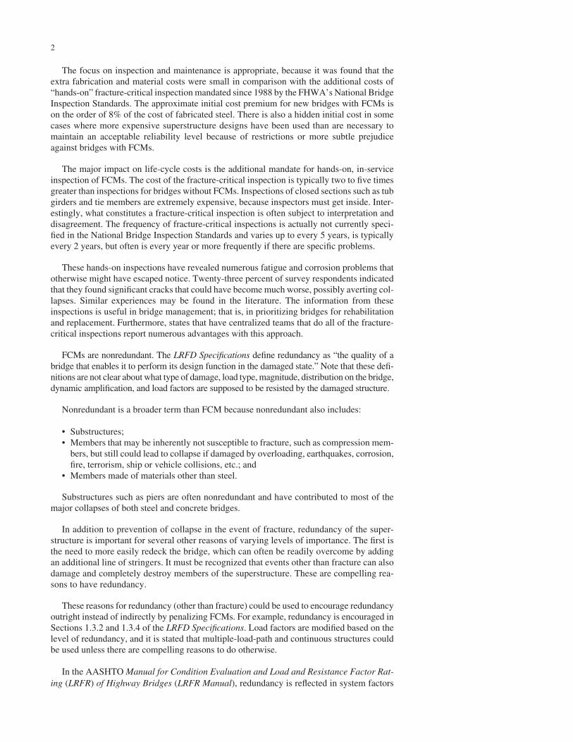
However, many older steel bridges built before the imple-mentation of modern fatigue design provisions in the mid-1970s possess poor fatigue details, such as cover plates thatcan develop fatigue cracks (Figure 2) (11), which if notrepaired, can grow and lead to fracture of the member andpossible collapse of part or all of the bridge.
Other factors that make these older bridges susceptible tofracture include:
• Marginal fracture toughness of the steel and weld metal;• Detailing, fabrication quality, and shop inspection below
modern standards;• Severe corrosion problems, especially at open or failing
expansion joints;• Higher traffic volumes and truck weights than the bridge
was originally designed to handle.
In light of these factors, periodic in-service inspection isparticularly important for older bridges to provide an oppor-tunity to detect cracks and corrosion before they grow to acritical size. In 1970, partly in reaction to the collapse of the
CHAPTER TWO
BACKGROUND
FIGURE 1 Collapse of Point Pleasant Bridge.
Point Pleasant Bridge over the Ohio River, the NBIS (4) wereestablished. Title 23, Code of Federal Regulations, Part 650,Subpart C sets forth the NBIS for all bridges of more than20 ft (6 m) span on all public roads. Section 650.3 specifiesinspection procedures and frequencies, indicates minimumqualifications for personnel, and states reporting, inventory,load posting, and inspection recordkeeping requirements. Thecurrent NBIS mandates a 2-year inspection interval for allhighway bridges carrying public roads.
However, modern steel bridges are not nearly as suscep-tible to fracture as older bridges (12,13). As a result, the waysmodern bridges are managed could possibly be evaluateddifferently than older bridges. This could be studied further,with considerable potential benefits.
For example, problems with severe corrosion have beenreduced. In the last 20 years, durability of weathering steeland coating systems has improved. Expansion joints havebeen improved if not eliminated through the use of continu-ous jointless bridges (14).
In addition, there have been few if any cases where welddefects or low-toughness steel has been an issue for modernsteel bridges, owing primarily to improvements in details,fabrication practices, and fracture toughness of the steel andweld metal (12,15). If spontaneous fracture from weld defectsis ruled out, then fracture can only occur if preceded byfatigue (15). Therefore, in this case, it is essentially sufficientto control fatigue to prevent fracture (12,15).
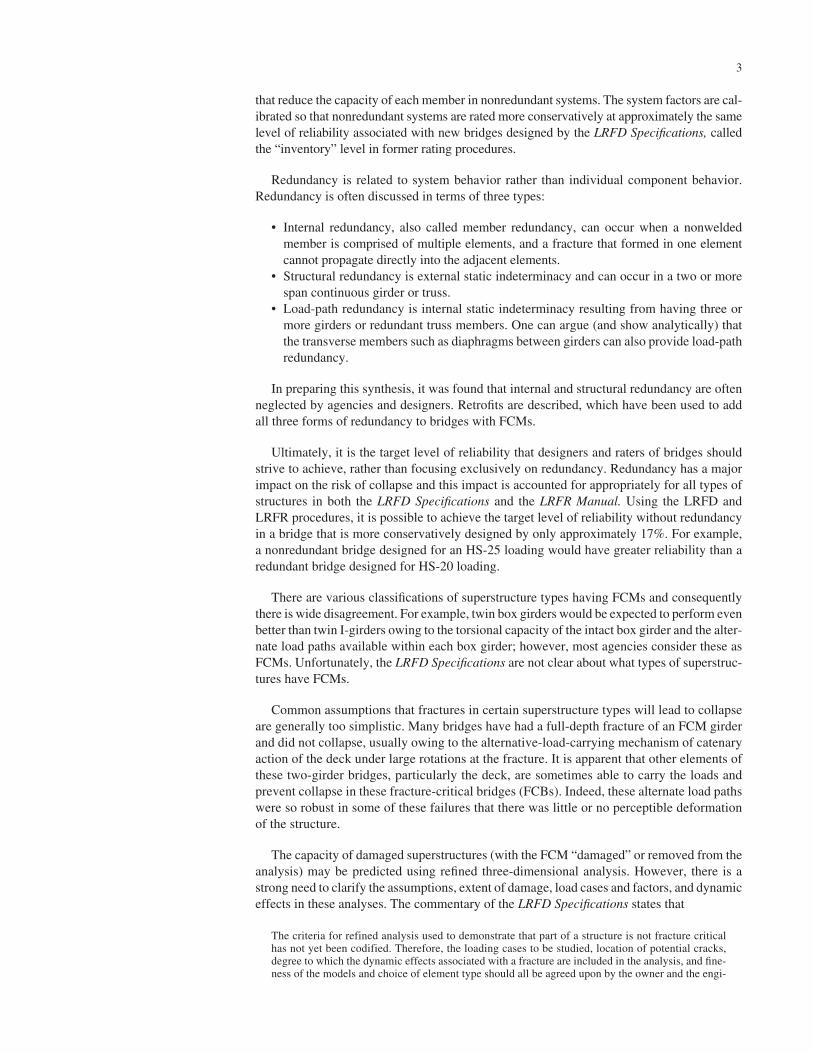
Distortion-induced fatigue cracking, discussed further in Appendix A, continued as a fatigue problem in typicalplate girder bridges designed before the mid-1980s (11,12,15,16). A common example of distortion-induced fatiguecracking is web-gap cracking, which occurs in the gap whena connection plate is not attached to a flange and is subjectto out-of-plane distortion (Figure 3). This problem was cor-
8
rected in 1985 by a change in AASHTO specifications thatmandated the attachment of the connection plate to bothflanges.
Hence, it is important to distinguish three different ageranges of steel bridges:
1. Steel bridges built before the implementation of modernfatigue design provisions in the mid-1970s.
2. Steel bridges designed after the mid-1970s, but before1985, which have fewer fatigue problems but remainsusceptible to distortion-induced fatigue.
3. Modern steel bridges designed after 1985 that shouldnot be susceptible to fatigue at all.
Fatigue is virtually unheard of in modern steel bridges asa result of improved design specifications, more fatigue-resistant details, and improvements in shop inspection(15,16). Fatigue problems that have occurred in modernbridges were typically the result of unintended behavior or a design error that is not consistent with the intent ofpresent specifications and usually manifest in the first fewyears of the life of the bridge. Although the bridges that are referred to herein as “modern” are less than 20 yearsold, there is substantial confidence that these structures willcontinue to perform with few problems resulting fromfatigue.
As a final note, in changing from load factor design (LFD)to LRFD, two-girder bridges will be designed more con-servatively than before. According to Dr. Dennis Mertz, incalibrating the LRFD specifications, loads were increasedslightly to compensate for improved and less conservativedistribution factors. However, the distribution factors fortwo-girder bridges were always reasonably accurate, so theydid not get the benefit of improved distribution factors thatmultigirder bridges did. This should be kept in mind whenconsidering the reliability of these two-girder and two-linetruss systems.
FIGURE 2 Development of fatigue crack at cover plate ends onthe multibeam Yellow Mill Pond Bridge in Connecticut in 1976.(Courtesy: John W. Fisher.)
Concrete Deck
Girder Flange
Girder Web
Crack
Cro
ssframe
FIGURE 3 Typical web-gap fatigue cracking.

9
Additional Material, Fabrication, and In-ServiceInspection Requirements for FCMs and Cost Impact
FHWA led the development of a fracture control plan (FCP)to provide a higher level of safety for FCBs. In the broadsense, an FCP includes everything that affects the potentialfor fracture—in-service inspection and maintenance as wellas design, fabrication, and shop inspection (17). The idea isthat trade-offs can be made between components of the planwithout compromising reliability. For example, better tough-ness could be required to compensate for relaxed in-serviceinspection standards, because better toughness would leadto a larger critical crack size that would be easier to see froma distance and that would take longer to develop. Efforts tomake FCBs more conservative were largely the result ofexperiences with cracking in tied arches, mostly owing tolarge fabrication defects because of difficulty associated withwelding A514 steel (11).
The American Iron and Steel Institute initiated a researchproject to develop an improved FCP for fabrication of non-redundant structures. This work (9,17–21) ultimately resultedin the 1978 publication of the AASHTO Guide Specificationfor Fracture Critical Non-Redundant Bridge Members (22).A key element was more stringent CVN requirements for basemetal and weld metal for FCMs.
This Guide Specification has now been withdrawn. TheCVN requirements for base metal, including the greaterrequirements for FCMs, are now included in the AASHTOLRFD Bridge Design Specifications (1), as well as the ASTMand AASHTO specifications for the steel (23,24). Most ofthe remaining material from the Guide Specification is nowincluded in Section 12 of AASHTO/AWS-D1.5, “AASHTO/AWS Fracture Control Plan (FCP) for Non-RedundantMembers” (2). Note that in AASHTO/AWS-D1.5 the defini-tion of an FCP is narrower, including only fabrication andshop inspection—not base metal selection, in-service inspec-tion, and maintenance. Therefore, these provisions will bereferred to as a fabrication FCP. (Unfortunately, yet anothercompletely different meaning for the term “fracture controlplan” has arisen and that is the plan- or elevation-view draw-ing identifying all FCMs for use in in-service inspection.)
The differences between the provisions for the fabricationof FCMs in Section 12 and the provisions for non-FCMselsewhere in AASHTO/AWS-D1.5 are primarily more strictfabrication and shop inspection requirements to control weldflaws and other crack-like defects in FCMs. For example,transverse groove welds are required to be inspected in theshop with both radiographic testing (RT) and ultrasonic test-ing (UT), whereas only RT is required for non-FCMs.
The fabrication FCP and the more stringent CVN require-ments result in an even lower probability of brittle fracture innew FCMs than for typical non-FCM members. Note that thisadditional fracture reliability does not apply to older FCMs
designed before implementation of the FCP in 1978 (22).The survey (described in chapter three) indicated that approx-imately 75% of FCBs in present inventory were designedbefore the FCP.
However, the fabrication provisions and the CVN require-ments for the materials of the fabrication FCP increase costs.One major bridge fabricator reported that the approximateincrease in initial costs for new FCMs relative to non-FCMsis on the order of 8% of the cost of fabricated steel.
In 1983, the Mianus River Bridge on I-95 in Connecticut(built in 1957) collapsed, killing three persons (Figure 4).Packout corrosion in a nonredundant pin and hanger assem-bly pushed one of the plates partly off the pin, eventuallyleading to a fatigue crack and collapse of the suspended span(between two cantilevers) (16,25,26). This event can be fur-ther attributed to poor maintenance, because a clogged drainwas partly responsible for the packout corrosion. Through-out the country there are numerous other bridges with similarpin and hanger details; however, this type of suspended spanis rarely if ever used in new designs. As with the eyebar of thePoint Pleasant Bridge, this bridge collapse demonstrated thatthese pin and hanger assemblies are also clearly FCMs. (Alsosimilar to the Point Pleasant Bridge collapse, the MianusRiver Bridge collapse was the result of extraordinary circum-stances, in this case corrosion, and not just fatigue or fracture.)
In part because of this failure, the NBIS were revised in1988, requiring among other things a hands-on inspection ofFCMs. This requirement significantly increases life-cyclecosts relative to non-FCMs, which may be inspected fromthe ground, through, in most cases, binoculars (27–29). Thisrequirement is particularly onerous for box girders, becauseit requires the inspectors to enter the boxes, which signifi-cantly increases costs. The frequency and extent of inspec-tion are not clear in the current NBIS. Consequently, there isdisagreement on what constitutes a fracture-critical inspec-tion and how often it is done. (When the word inspection is
FIGURE 4 Collapse of Mianus River Bridge. (Courtesy: JohnW. Fisher.)

used throughout the rest of this report, it is intended to meanfracture-critical, hands-on field inspection, unless otherwisenoted.)
These increased life-cycle costs for FCMs are signifi-cantly greater than the approximately 8% increase in initialmaterials and fabrication costs for FCMs discussed earlier.According to the survey (and as described later in chapterthree), many owners believe that inspection costs associatedwith FCBs consume a large portion of their entire inspectionbudget. Owners were asked to estimate the relative increasein costs when inspecting an FCB relative to inspection andnon-FCBs. There was substantial variation in the response;however, most agencies indicated increases of between 200%and 500%. The most common reasons indicated for theseincreases were:
• Specialized access equipment such as a snooper (Fig-ure 5), manlift (Figure 6), or rigging required for hands-on inspection (30).
• Traffic control to close lanes to permit the access equip-ment to be placed on or below the bridge (see Figure 5).
• Additional employee-hours required to conduct a detailedhands-on inspection.
• More frequent use of nondestructive testing (NDT)(described in Appendix A).
• Greater frequency of inspection for FCBs.
These hands-on inspections have revealed numerous fatigueand corrosion problems that otherwise might have escapednotice. Many of these problem details are discussed in Appen-dix A. Twenty-three percent of respondents to the survey indi-cated that they found significant cracks that could have becomemuch worse, possibly averting collapses (see chapter three).Similar examples may be found in trade magazines [e.g., seeZettler (31)].
10
Primarily because of these increased life-cycle costs, thereis a general reluctance to design new FCBs. Fewer FCBs havebeen proposed since the fabrication FCP went into effect in1978 (22). FCMs, such as steel pier caps and cross girders, arestill frequently designed, although usually only if they cannotbe avoided. In some circumstances, bridge designs with FCMs,such as tied arches, two-girder bridges, and trusses, may be themost efficient and cost-effective structural system. Althoughthe more stringent CVN requirements, the fabrication FCP,and the additional inspection requirements for FCMs arebeneficial, if they are overly conservative for modern bridgesthey can become an obstacle to the savings gained in usingmore cost-effective designs.
International scanning tours for bridge management (32)and fabrication (33) have noted that Europe does not havespecial policies for FCMs. A risk-based approach, coupledwith more rigorous three-dimensional analysis techniques, isused to ensure that a sufficient level of structural reliabilityis provided. Consequently, steel bridge designs that would beconsidered fracture-critical in the United States are still com-monly built without prejudice. However, they have also hadfailures of what we would consider FCBs.
The following is from the fabrication scanning tourreport (33):
Perhaps the most significant design-related observation of thescan team was the rest of the industrialized world’s more liberalview of the importance of redundancy. Two-girder bridges, aswell as other structure types considered nonredundant andfracture critical in the United States, are not discouraged and,in fact, are used extensively as safe and cost-effective bridgedesigns. Kawada Industries cited redundancy studies it performedto demonstrate adequate redundancy of its two-girder systemswith widely spaced, mid-depth cross beams. No special design,fabrication, or inspection requirements for such bridges wereapparent. The U.S. design philosophy for nonredundant bridgesshould be reconsidered, based upon these observations andimprovements in steel toughness.
Twin-girder railroad bridges are common in Germany. Thesingle-cell box girder, commonly used for elevated roadways in
FIGURE 5 Snooper used for hands-on inspection from bridgedeck.
FIGURE 6 Hands-on inspection from manlift.
11
urban areas of Japan, would be classified as fracture critical inthe United States, but has provided excellent performance.
Other interesting findings from the scanning tours werethat the inspection frequency is risk-based in Europe and thatthe inspectors’ qualifications are commensurate with thecomplexity of the bridge.
REDUNDANCY AND COLLAPSE OF STEEL BRIDGES
Definition of Redundancy and Contrast to Indeterminacy and FCMs
The AASHTO LRFD Bridge Design Specifications defineredundancy as “the quality of a bridge that enables it to per-form its design function in the damaged state.” In NCHRPReport 406 (34), Ghosn and Moses defined superstructureredundancy as “the capability of a bridge superstructure tocontinue to carry loads after the damage or the failure ofone of its members,” and this definition is also used in theAASHTO Manual for Condition Evaluation and Load andResistance Factor Rating (LRFR) of Highway Bridges (3).Even though it has to do with potential performance in theevent of damage, redundancy is a quality of the undamagedstructure.
Note that these definitions are not clear about what loadtype, magnitude, distribution on the bridge, dynamic ampli-fication, and load factors are supposed to be resisted by thedamaged structure. Ghosn and Moses attempted to set require-ments for the residual capacity of the damaged superstruc-ture (34).
The definitions of redundancy are also not clear regardingthe type and extent of damage. For example, in a bolted orriveted built-up member it is likely that a fracture would belimited to only one tension element, because it cannot prop-agate directly into neighboring elements. However, a shipcollision could destroy the entire member.
Ultimately, it is the target level of reliability that designersand engineers who rate bridges should strive to achieve andthe focus should not exclusively be on redundancy. Redun-dancy has a major impact on the risk of collapse and thisimpact is accounted for appropriately for all types of struc-tures in both the LRFD Specifications and the LRFR Manual,as discussed here. Using the LRFD and LRFR procedures, itis possible to achieve the target level of reliability withoutredundancy in a bridge that is more conservatively designed.
Structural redundancy and structural indeterminacy areoften confused and used interchangeably, although they arereally two separate issues. Structural indeterminacy simplyrefers to whether or not the forces in a structure can be deter-mined with statics. A structure that is indeterminate, althoughpossibly providing alternate load paths, would not meet thedefinition of redundant if it were to collapse, because the
members in the alternate load path did not have sufficientcapacity to carry the redistributed loads. It is also true, butless obvious, that there are determinate structures that can beshown to meet the definition of redundant by developing newalternative load paths—and even a few examples (discussedlater) of determinate structures that have demonstrated thatthey meet the definition of redundant by surviving a signifi-cant fracture in service.
As defined in the introduction, FCMs are nonredundant;however, nonredundant is a broader term because it alsoincludes
• Substructures;• Members that may be inherently not susceptible to frac-
ture, such as compression members, but still could leadto collapse if damaged by overloading, earthquakes, fire,terrorism, ship or vehicle collisions; and
• Members made of materials other than steel.
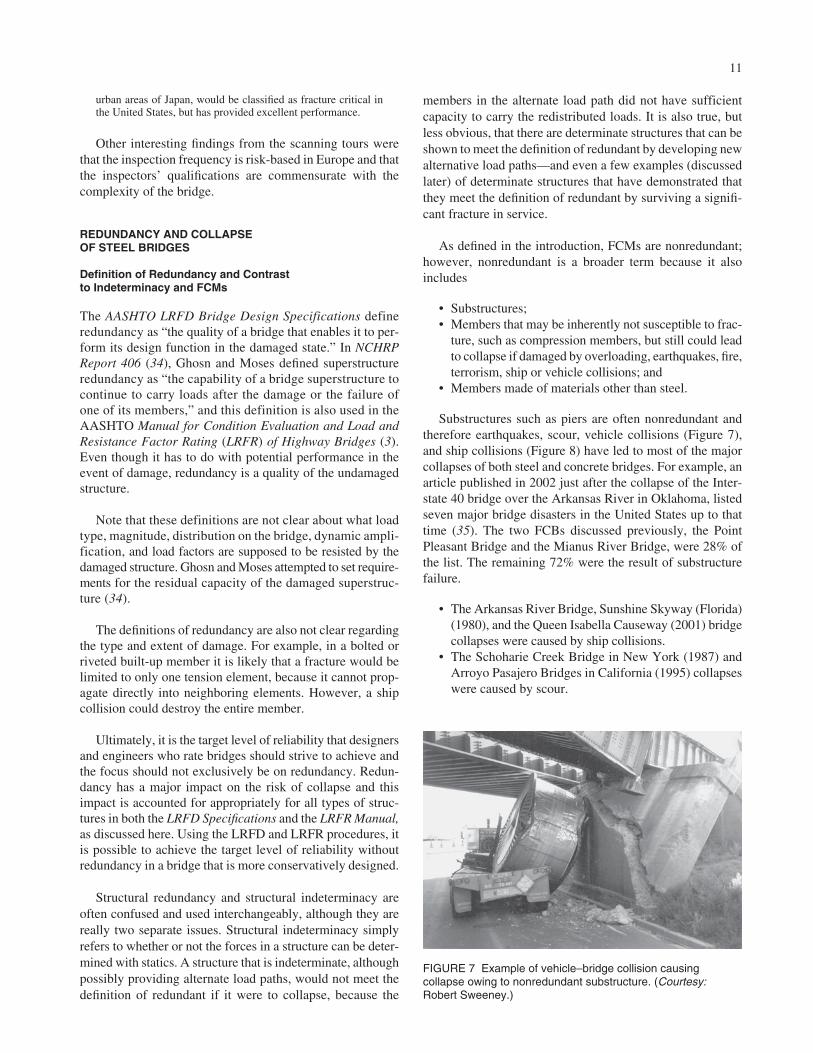
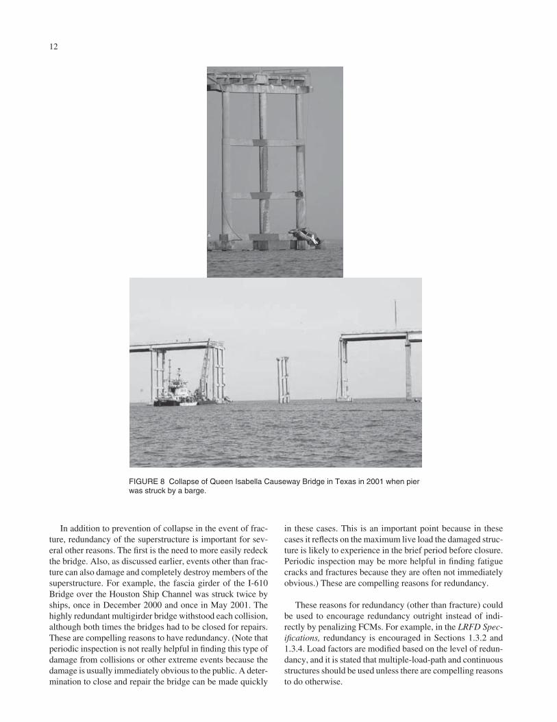
Substructures such as piers are often nonredundant andtherefore earthquakes, scour, vehicle collisions (Figure 7),and ship collisions (Figure 8) have led to most of the majorcollapses of both steel and concrete bridges. For example, anarticle published in 2002 just after the collapse of the Inter-state 40 bridge over the Arkansas River in Oklahoma, listedseven major bridge disasters in the United States up to thattime (35). The two FCBs discussed previously, the PointPleasant Bridge and the Mianus River Bridge, were 28% ofthe list. The remaining 72% were the result of substructurefailure.
• The Arkansas River Bridge, Sunshine Skyway (Florida)(1980), and the Queen Isabella Causeway (2001) bridgecollapses were caused by ship collisions.
• The Schoharie Creek Bridge in New York (1987) andArroyo Pasajero Bridges in California (1995) collapseswere caused by scour.
FIGURE 7 Example of vehicle–bridge collision causingcollapse owing to nonredundant substructure. (Courtesy:Robert Sweeney.)
In addition to prevention of collapse in the event of frac-ture, redundancy of the superstructure is important for sev-eral other reasons. The first is the need to more easily redeckthe bridge. Also, as discussed earlier, events other than frac-ture can also damage and completely destroy members of thesuperstructure. For example, the fascia girder of the I-610Bridge over the Houston Ship Channel was struck twice byships, once in December 2000 and once in May 2001. Thehighly redundant multigirder bridge withstood each collision,although both times the bridges had to be closed for repairs.These are compelling reasons to have redundancy. (Note thatperiodic inspection is not really helpful in finding this type ofdamage from collisions or other extreme events because thedamage is usually immediately obvious to the public. A deter-mination to close and repair the bridge can be made quickly
12
in these cases. This is an important point because in thesecases it reflects on the maximum live load the damaged struc-ture is likely to experience in the brief period before closure.Periodic inspection may be more helpful in finding fatiguecracks and fractures because they are often not immediatelyobvious.) These are compelling reasons for redundancy.
These reasons for redundancy (other than fracture) couldbe used to encourage redundancy outright instead of indi-rectly by penalizing FCMs. For example, in the LRFD Spec-ifications, redundancy is encouraged in Sections 1.3.2 and1.3.4. Load factors are modified based on the level of redun-dancy, and it is stated that multiple-load-path and continuousstructures should be used unless there are compelling reasonsto do otherwise.
FIGURE 8 Collapse of Queen Isabella Causeway Bridge in Texas in 2001 when pierwas struck by a barge.
13
In the LRFR Manual, redundancy is reflected in systemfactors that reduce the capacity of each member in non-redundant systems. The system factors are calibrated so thatnonredundant systems are rated more conservatively atapproximately the same level of reliability associated withnew bridges designed using LRFD Specifications, called the“inventory” level in former rating procedures. Redundantsystems are rated at a reduced reliability level correspondingapproximately to the traditional “operating” level. The sys-tem factor for the most nonredundant bridge types is 0.85.This means that a nonredundant bridge designed for 1.17 (theinverse of 0.85) times the design load has approximatelyequal reliability to a redundant bridge designed for 1.0 timesthe design load.
According to Ghosn and Moses (34), a redundant super-structure has at least one alternate load path and is capable ofsafely supporting the specified dead loads and live loads andmaintaining temporary serviceability of the deck followingfailure of a main load-carrying member. They recognized thatredundancy is related to system behavior rather than individ-ual component behavior. The specifications generally ignorethe interaction between members and structural components(i.e., system behavior) in a bridge, however.
Redundancy is often discussed in terms of three types (28,29,34):
• Internal redundancy, also called member redundancy,exists when a member is comprised of multiple elementsand a fracture that formed in one element cannot propa-gate directly into the adjacent elements. Examples includegirders with composite deck (the deck remains intact inthe event of a girder fracture as in Figure 9); riveted orbolted built-up girders, tie girders, or tension membersof a truss (Figure 10); split box sections with longitudi-
nal bolted splice (Figure 11); the bracing system, later-als and cross frames within a box member (Figure 12);bolted continuous plates or shapes to give a memberredundancy (Figures 13–15), and single-cell concreteboxes with multiple post-tensioning strands. Note that itmust be shown that the damaged member (several pos-sible cases considered separately with one element frac-tured or removed) can survive the prescribed loads to beinternally redundant.
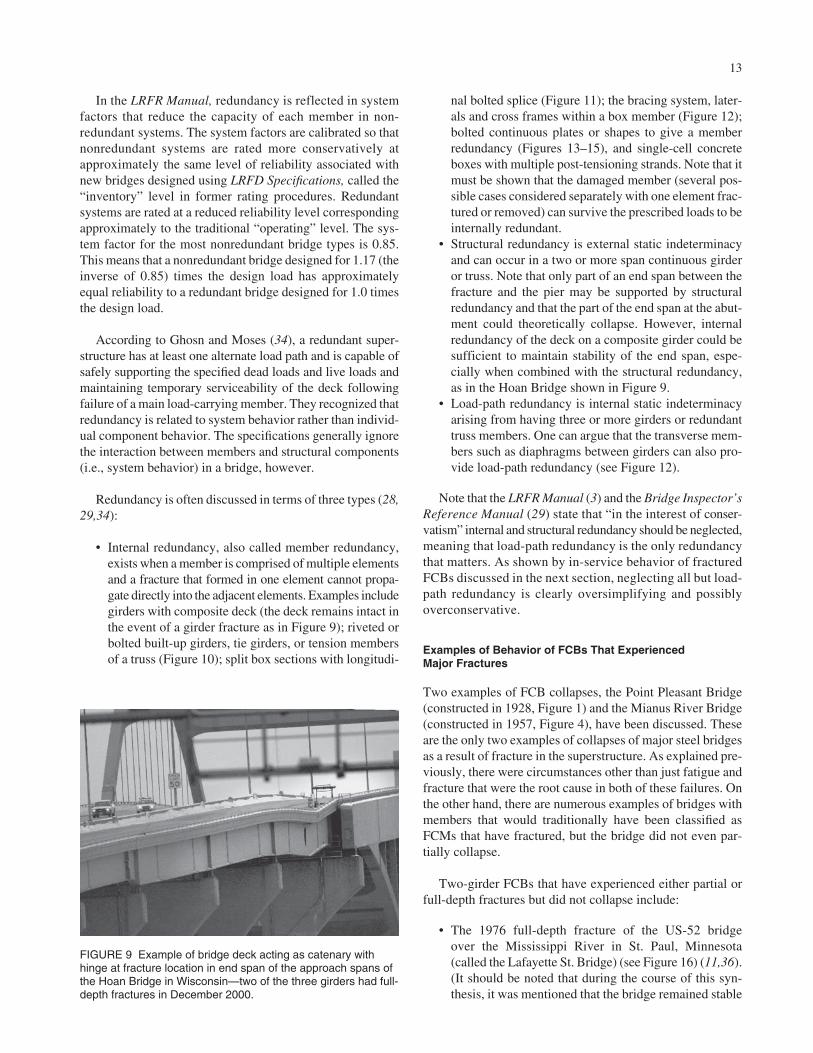
• Structural redundancy is external static indeterminacyand can occur in a two or more span continuous girderor truss. Note that only part of an end span between thefracture and the pier may be supported by structuralredundancy and that the part of the end span at the abut-ment could theoretically collapse. However, internalredundancy of the deck on a composite girder could besufficient to maintain stability of the end span, espe-cially when combined with the structural redundancy,as in the Hoan Bridge shown in Figure 9.
• Load-path redundancy is internal static indeterminacyarising from having three or more girders or redundanttruss members. One can argue that the transverse mem-bers such as diaphragms between girders can also pro-vide load-path redundancy (see Figure 12).
Note that the LRFR Manual (3) and the Bridge Inspector’sReference Manual (29) state that “in the interest of conser-vatism” internal and structural redundancy should be neglected,meaning that load-path redundancy is the only redundancythat matters. As shown by in-service behavior of fracturedFCBs discussed in the next section, neglecting all but load-path redundancy is clearly oversimplifying and possiblyoverconservative.
Examples of Behavior of FCBs That ExperiencedMajor Fractures
Two examples of FCB collapses, the Point Pleasant Bridge(constructed in 1928, Figure 1) and the Mianus River Bridge(constructed in 1957, Figure 4), have been discussed. Theseare the only two examples of collapses of major steel bridgesas a result of fracture in the superstructure. As explained pre-viously, there were circumstances other than just fatigue andfracture that were the root cause in both of these failures. Onthe other hand, there are numerous examples of bridges withmembers that would traditionally have been classified asFCMs that have fractured, but the bridge did not even par-tially collapse.
Two-girder FCBs that have experienced either partial orfull-depth fractures but did not collapse include:
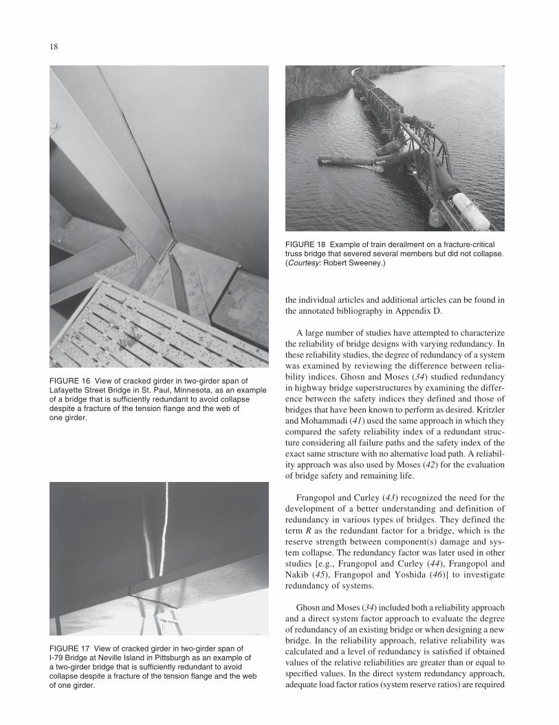
• The 1976 full-depth fracture of the US-52 bridge over the Mississippi River in St. Paul, Minnesota(called the Lafayette St. Bridge) (see Figure 16) (11,36).(It should be noted that during the course of this syn-thesis, it was mentioned that the bridge remained stable
FIGURE 9 Example of bridge deck acting as catenary withhinge at fracture location in end span of the approach spans ofthe Hoan Bridge in Wisconsin—two of the three girders had full-depth fractures in December 2000.

because it leaned on an adjacent bridge). However,interviews with Donald Fleming, former Bridge Engi-neer of the Minnesota Department of Transportation(DOT) and John W. Fisher, both of whom weredirectly involved with the failure investigation, con-firmed that this was not the case. The bridge did sag 6.5 in. (165 mm), but was not supported by the adjacentbridge.
14
• The 1977 full-depth fracture of the I-79 bridge at NevilleIsland in Pittsburgh, Pennsylvania (Figure 17) (11,15).
• The May 2003 fracture of the US-422 Bridge nearPottstown, Pennsylvania. The entire bottom flange andapproximately 9 in. (230 mm) of the web fractured (37).
It is apparent that other elements of these two-girderbridges, particularly the deck, along with the floorbeams, cross-
PL 1 1/8
PL 1 3/4
PL 1 1/8
PL 1 x 7 7/8 (TYP)
CL SPLICE
FLANGE SPLICE
CL SPLICE
WEB SPLICE
3'-0
"
5'-3"
3"
6 1/
4"
6'-8
"
6 1/
4"
3"
2'-9"
(a)
(b)
FIGURE 10 Examples of internally redundant members: (a) riveted built-up girder and (b) bolted built-up tie girder proposedfor Blennerhassett Arch Bridge. (Courtesy: Michael Baker Jr., Inc.)

15
frames, and stringers, are sometimes able to carry the loads andprevent collapse. These alternate load paths were so robust inthe I-79 and US-422 fractures that there was little or no per-ceptible deformation of the structure. For example, when atugboat pilot discovered the I-79 fracture, the bridge was stillproviding a serviceable roadway. In the case of the LafayetteSt. Bridge, displacements of 2.5 in. (63 mm) were noticedrelative to the adjacent bridge 48 days before the fracture wasdiscovered, growing to 6.5 in. (230 mm) as the crack lengthincreased over that time.
The less obvious nature of the damage in the case of afracture as opposed to the other causes such as collisions
discussed previously has implications for the loading toevaluate the damaged member (residual capacity). A lowerlevel of residual capacity would be required for membersdamaged by these other more obvious causes because thebridge is likely to be closed within hours after the event.However, if a fracture goes unnoticed for an extended period,the probability of larger permits or illegal loads increasessignificantly.
As explained in chapter three, some agencies even classifythree-girder bridges as FCBs. The Hoan Bridge fracture, shownin Figure 9, is an example of a three-girder bridge end span(which is viewed as most critical owing to inadequate con-
FIGURE 11 Splitting a box section with a bolted longitudinal splice to give it internal redundancy. (Courtesy: HNTB.)
Truss action between slab and diaphragm
FIGURE 12 Schematic of twin composite tub girder superstructure showinginternal redundancy provided by bracing system and possible alternative loadpath provided by slab and diaphragm. (Courtesy: HNTB.)

16
Lowerchord
Redundancyplate
FIGURE 13 Redundancy plate bolted to lower chord of SR-33bridge near Easton, Pennsylvania. (Courtesy: HNTB.)
FIGURE 14 Tee section bolted to continuous lower flange of box section to provide redundancy. (Courtesy: HNTB.)
tinuity at the joint), with two out of three girders and the webof the third girder fractured (38).
These fractures in actual bridges are the most valuabledata available to judge the necessity of special provisions forFCMs. These full-scale tests are much more valuable thanlaboratory tests or numerical simulations, because the for-mer are subject to idealizations and assumptions. Althoughnot sufficient to prove that two-girder bridges should not beclassified as having FCMs, these incidents do show thatunder some circumstances they do not meet the definition ofan FCM.
The survey (see chapter three) revealed several other exam-ples of FCBs that had experienced major fractures but hadnot collapsed. These were usually noticed in an inspection,but had occurred at an earlier, unknown time. Similar accountscan be found elsewhere (31,39).
Although not caused by a fracture, a train derailment on anonredundant truss bridge, shown in Figure 18, is anotherexample of valuable in-service behavior of a full-scale bridge.Note that several diagonals, hangers, and upper chord bracesare completely severed, but the truss did not collapse eventhough a significant portion of the live load remained on thebridge.
17
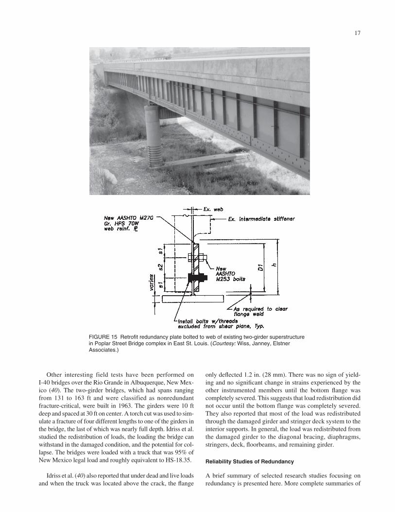
Other interesting field tests have been performed on I-40 bridges over the Rio Grande in Albuquerque, New Mex-ico (40). The two-girder bridges, which had spans rangingfrom 131 to 163 ft and were classified as nonredundantfracture-critical, were built in 1963. The girders were 10 ftdeep and spaced at 30 ft on center. A torch cut was used to sim-ulate a fracture of four different lengths to one of the girders inthe bridge, the last of which was nearly full depth. Idriss et al.studied the redistribution of loads, the loading the bridge canwithstand in the damaged condition, and the potential for col-lapse. The bridges were loaded with a truck that was 95% ofNew Mexico legal load and roughly equivalent to HS-18.35.
Idriss et al. (40) also reported that under dead and live loadsand when the truck was located above the crack, the flange
only deflected 1.2 in. (28 mm). There was no sign of yield-ing and no significant change in strains experienced by theother instrumented members until the bottom flange wascompletely severed. This suggests that load redistribution didnot occur until the bottom flange was completely severed.They also reported that most of the load was redistributedthrough the damaged girder and stringer deck system to theinterior supports. In general, the load was redistributed fromthe damaged girder to the diagonal bracing, diaphragms,stringers, deck, floorbeams, and remaining girder.
Reliability Studies of Redundancy
A brief summary of selected research studies focusing onredundancy is presented here. More complete summaries of
FIGURE 15 Retrofit redundancy plate bolted to web of existing two-girder superstructurein Poplar Street Bridge complex in East St. Louis. (Courtesy: Wiss, Janney, ElstnerAssociates.)
18
the individual articles and additional articles can be found inthe annotated bibliography in Appendix D.
A large number of studies have attempted to characterizethe reliability of bridge designs with varying redundancy. Inthese reliability studies, the degree of redundancy of a systemwas examined by reviewing the difference between relia-bility indices. Ghosn and Moses (34) studied redundancyin highway bridge superstructures by examining the differ-ence between the safety indices they defined and those ofbridges that have been known to perform as desired. Kritzlerand Mohammadi (41) used the same approach in which theycompared the safety reliability index of a redundant struc-ture considering all failure paths and the safety index of theexact same structure with no alternative load path. A reliabil-ity approach was also used by Moses (42) for the evaluationof bridge safety and remaining life.
Frangopol and Curley (43) recognized the need for thedevelopment of a better understanding and definition ofredundancy in various types of bridges. They defined theterm R as the redundant factor for a bridge, which is thereserve strength between component(s) damage and sys-tem collapse. The redundancy factor was later used in otherstudies [e.g., Frangopol and Curley (44), Frangopol andNakib (45), Frangopol and Yoshida (46)] to investigateredundancy of systems.
Ghosn and Moses (34) included both a reliability approachand a direct system factor approach to evaluate the degreeof redundancy of an existing bridge or when designing a newbridge. In the reliability approach, relative reliability wascalculated and a level of redundancy is satisfied if obtainedvalues of the relative reliabilities are greater than or equal tospecified values. In the direct system redundancy approach,adequate load factor ratios (system reserve ratios) are required
FIGURE 16 View of cracked girder in two-girder span ofLafayette Street Bridge in St. Paul, Minnesota, as an exampleof a bridge that is sufficiently redundant to avoid collapsedespite a fracture of the tension flange and the web of one girder.
FIGURE 17 View of cracked girder in two-girder span of I-79 Bridge at Neville Island in Pittsburgh as an example of a two-girder bridge that is sufficiently redundant to avoidcollapse despite a fracture of the tension flange and the web of one girder.
FIGURE 18 Example of train derailment on a fracture-criticaltruss bridge that severed several members but did not collapse.(Courtesy: Robert Sweeney.)
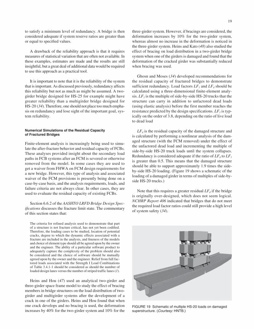
19
to satisfy a minimum level of redundancy. A bridge is thenconsidered adequate if system reserve ratios are greater thanor equal to specified values.
A drawback of the reliability approach is that it requiresmeasures of statistical variation that are often not available. Inthese examples, estimates are made and the results are stillinsightful, but a great deal of additional data would be requiredto use this approach as a practical tool.
It is important to note that it is the reliability of the systemthat is important. As discussed previously, redundancy affectsthis reliability but not as much as might be assumed. A two-girder bridge designed for HS-25 for example might havegreater reliability than a multigirder bridge designed forHS-20 (34). Therefore, one should not place too much empha-sis on redundancy and lose sight of the important goal, sys-tem reliability.
Numerical Simulations of the Residual Capacity of Fractured Bridges
Finite-element analysis is increasingly being used to simu-late the after-fracture behavior and residual capacity of FCBs.These analyses provided insight about the secondary loadpaths in FCB systems after an FCM is severed or otherwiseremoved from the model. In some cases they are used toget a waiver from FHWA on FCM design requirements fora new bridge. However, this type of analysis and associatedwaiver of the FCM provisions is presently being done on acase-by-case basis, and the analysis requirements, loads, andfailure criteria are not always clear. In other cases, they areused to evaluate the residual capacity of existing FCBs.
Section 6.6.2 of the AASHTO LRFD Bridge Design Spec-ifications discusses the fracture limit state. The commentaryof this section states that:
The criteria for refined analysis used to demonstrate that partof a structure is not fracture critical, has not yet been codified.Therefore, the loading cases to be studied, location of potentialcracks, degree to which the dynamic effects associated with afracture are included in the analysis, and fineness of the modelsand choice of element type should all be agreed upon by the ownerand the engineer. The ability of a particular software product toadequately capture the complexity of the problem should alsobe considered and the choice of software should be mutuallyagreed upon by the owner and the engineer. Relief from full fac-tored loads associated with the Strength I Load Combinationsof Table 3.4.1-1 should be considered as should the number ofloaded design lanes versus the number of striped traffic lanes (1).
Heins and Hou (47) used an analytical two-girder andthree-girder space frame model to study the effect of bracingmembers in bridge structures on the load distribution of two-girder and multigirder systems after the development of acrack in one of the girders. Heins and Hou found that whenone crack develops and no bracing is used, the deformationincreases by 40% for the two-girder system and 10% for the
three-girder system. However, if bracings are considered, thedeformation increases by 10% for the two-girder system,whereas almost no increase in the deformation is noticed inthe three-girder system. Heins and Kato (48) also studied theeffect of bracing on load distribution in a two-girder bridgesystem when one of the girders is damaged and found that thedeformation of the cracked girder was substantially reducedwhen bracing was used.
Ghosn and Moses (34) developed recommendations forthe residual capacity of fractured bridges to demonstratesufficient redundancy. Load factors LF1 and LFd should becalculated using a three-dimensional finite-element analy-sis. LF1 is the multiple of side-by-side HS-20 trucks that thestructure can carry in addition to unfactored dead loads(using elastic analysis) before the first member reaches theresistance predicted by the design specifications. LF1 is typ-ically on the order of 3.8, depending on the ratio of live loadto dead load
LFd is the residual capacity of the damaged structure andis calculated by performing a nonlinear analysis of the dam-aged structure (with the FCM removed) under the effect ofthe unfactored dead load and incrementing the multiple ofside-by-side HS-20 truck loads until the system collapses.Redundancy is considered adequate if the ratio of LFd to LF1
is greater than 0.5. This means that the damaged structureshould be able to support approximately 1.9 times the side-by-side HS-20 loading. (Figure 19 shows a schematic of theloading of a damaged girder in terms of multiples of side-by-side HS-20 trucks.)
Note that this requires a greater residual LFd if the bridgeis originally over-designed, which does not seem logical.NCHRP Report 406 indicated that bridges that do not meetthe required load factor ratios could still provide a high levelof system safety (34).
FIGURE 19 Schematic of multiple HS-20 loads on damagedsuperstructure. (Courtesy: HNTB.)
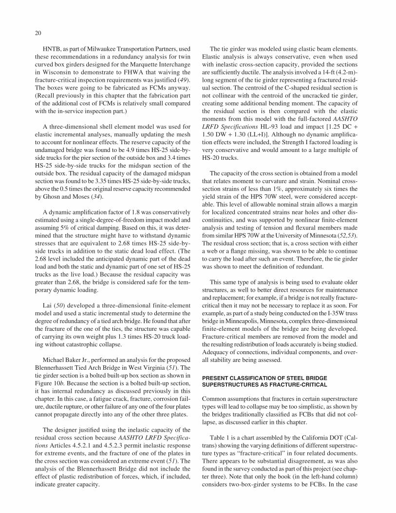
HNTB, as part of Milwaukee Transportation Partners, usedthese recommendations in a redundancy analysis for twincurved box girders designed for the Marquette Interchangein Wisconsin to demonstrate to FHWA that waiving thefracture-critical inspection requirements was justified (49).The boxes were going to be fabricated as FCMs anyway.(Recall previously in this chapter that the fabrication partof the additional cost of FCMs is relatively small comparedwith the in-service inspection part.)
A three-dimensional shell element model was used forelastic incremental analyses, manually updating the meshto account for nonlinear effects. The reserve capacity of theundamaged bridge was found to be 4.9 times HS-25 side-by-side trucks for the pier section of the outside box and 3.4 timesHS-25 side-by-side trucks for the midspan section of theoutside box. The residual capacity of the damaged midspansection was found to be 3.35 times HS-25 side-by-side trucks,above the 0.5 times the original reserve capacity recommendedby Ghosn and Moses (34).
A dynamic amplification factor of 1.8 was conservativelyestimated using a single-degree-of-freedom impact model andassuming 5% of critical damping. Based on this, it was deter-mined that the structure might have to withstand dynamicstresses that are equivalent to 2.68 times HS-25 side-by-side trucks in addition to the static dead load effect. (The2.68 level included the anticipated dynamic part of the deadload and both the static and dynamic part of one set of HS-25trucks as the live load.) Because the residual capacity wasgreater than 2.68, the bridge is considered safe for the tem-porary dynamic loading.
Lai (50) developed a three-dimensional finite-elementmodel and used a static incremental study to determine thedegree of redundancy of a tied arch bridge. He found that afterthe fracture of the one of the ties, the structure was capableof carrying its own weight plus 1.3 times HS-20 truck load-ing without catastrophic collapse.
Michael Baker Jr., performed an analysis for the proposedBlennerhassett Tied Arch Bridge in West Virginia (51). Thetie girder section is a bolted built-up box section as shown inFigure 10b. Because the section is a bolted built-up section,it has internal redundancy as discussed previously in thischapter. In this case, a fatigue crack, fracture, corrosion fail-ure, ductile rupture, or other failure of any one of the four platescannot propagate directly into any of the other three plates.
The designer justified using the inelastic capacity of theresidual cross section because AASHTO LRFD Specifica-tions Articles 4.5.2.1 and 4.5.2.3 permit inelastic responsefor extreme events, and the fracture of one of the plates inthe cross section was considered an extreme event (51). Theanalysis of the Blennerhassett Bridge did not include theeffect of plastic redistribution of forces, which, if included,indicate greater capacity.
20
The tie girder was modeled using elastic beam elements.Elastic analysis is always conservative, even when usedwith inelastic cross-section capacity, provided the sectionsare sufficiently ductile. The analysis involved a 14-ft (4.2-m)-long segment of the tie girder representing a fractured resid-ual section. The centroid of the C-shaped residual section isnot collinear with the centroid of the uncracked tie girder,creating some additional bending moment. The capacity ofthe residual section is then compared with the elasticmoments from this model with the full-factored AASHTOLRFD Specifications HL-93 load and impact [1.25 DC +1.50 DW + 1.30 (LL+I)]. Although no dynamic amplifica-tion effects were included, the Strength I factored loading isvery conservative and would amount to a large multiple ofHS-20 trucks.
The capacity of the cross section is obtained from a modelthat relates moment to curvature and strain. Nominal cross-section strains of less than 1%, approximately six times theyield strain of the HPS 70W steel, were considered accept-able. This level of allowable nominal strain allows a marginfor localized concentrated strains near holes and other dis-continuities, and was supported by nonlinear finite-elementanalysis and testing of tension and flexural members madefrom similar HPS 70W at the University of Minnesota (52,53).The residual cross section; that is, a cross section with eithera web or a flange missing, was shown to be able to continueto carry the load after such an event. Therefore, the tie girderwas shown to meet the definition of redundant.
This same type of analysis is being used to evaluate olderstructures, as well to better direct resources for maintenanceand replacement; for example, if a bridge is not really fracture-critical then it may not be necessary to replace it as soon. Forexample, as part of a study being conducted on the I-35W trussbridge in Minneapolis, Minnesota, complex three-dimensionalfinite-element models of the bridge are being developed.Fracture-critical members are removed from the model andthe resulting redistribution of loads accurately is being studied.Adequacy of connections, individual components, and over-all stability are being assessed.
PRESENT CLASSIFICATION OF STEEL BRIDGESUPERSTRUCTURES AS FRACTURE-CRITICAL
Common assumptions that fractures in certain superstructuretypes will lead to collapse may be too simplistic, as shown bythe bridges traditionally classified as FCBs that did not col-lapse, as discussed earlier in this chapter.
Table 1 is a chart assembled by the California DOT (Cal-trans) showing the varying definitions of different superstruc-ture types as “fracture-critical” in four related documents.There appears to be substantial disagreement, as was alsofound in the survey conducted as part of this project (see chap-ter three). Note that only the book (in the left-hand column)considers two-box-girder systems to be FCBs. In the case
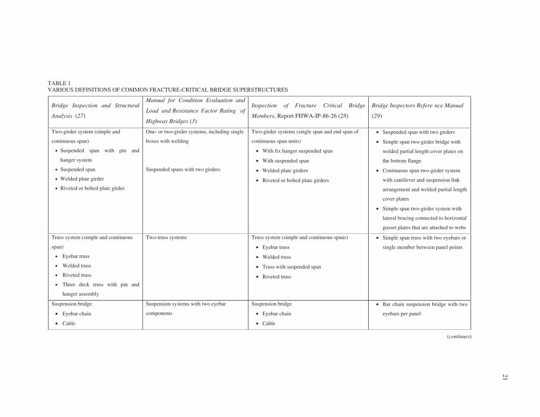
21
Bridge Inspection and Structural
Analysis (27)
Manual for Condition Evaluation and
Load and Resistance Factor Rating of
Highway Bridges (3)
Inspection of Fracture Critical Bridge
Members, Report FHWA-IP-86-26 (28)
Bridge Inspectorís Refere nce Manual
(29)
Two-girder system (simple and
continuous span)
• Suspended span with pin and
hanger system
• Suspended span
• Welded plate girder
• Riveted or bolted plate girder
One- or two-girder systems, including single
boxes with welding
Suspended spans with two girders
Two-girder systems (single span and end span of
continuous span units)
• With fix hanger suspended span
• With suspended span
• Welded plate girders
• Riveted or bolted plate girders
• Suspended span with two girders
• Simple span two-girder bridge with
welded partial length cover plates on
the bottom flange
• Continuous span two-girder system
with cantilever and suspension link
arrangement and welded partial length
cover plates
• Simple span two-girder system with
lateral bracing connected to horizontal
gusset plates that are attached to webs
Truss system (simple and continuous
span)
• Eyebar truss
• Welded truss
• Riveted truss
• Three deck truss with pin and
hanger assembly
Two-truss systems Truss system (simple and continuous spans)
• Eyebar truss
• Welded truss
• Truss with suspended span
• Riveted truss
• Simple span truss with two eyebars or
single member between panel points
Suspension bridge
• Eyebar chain
• Cable
Suspension systems with two eyebar
components
Suspension bridge
• Eyebar chain
• Cable
• Bar chain suspension bridge with two
eyebars per panel
TABLE 1VARIOUS DEFINITIONS OF COMMON FRACTURE-CRITICAL BRIDGE SUPERSTRUCTURES
(continues)

22
• Welded tie box girder
• Riveted tie box girder
Welded tie arches • Two welded tie box girder
• Two riveted tie box girder
Steel pier cap
• Welded box or plate girder
• Riveted box or plate girder
• Two column steel bent
Steel pier caps and cross girders Steel pier cap
• Welded box or plate girder
• Riveted plate girder
• Single welded I-girder or box girder
pier cap with bridge girders and
stringers attached by welding
Longitudinal box beam
• Single welded box
• Single riveted box
Single boxes with welding Longitudinal box beam
• Single welded box
• Single riveted box
• Simple span single welded box girders
with details such as termination of
longitudinal stiffeners or gusset plate
Anchor for cable stayed bridge
Pin and hanger connections when used
in suspended span configuration in
nonredundant systems
Pin and hanger connections on two- or three-
girder systems
Two or less box girders
Three or more box girders if spacing is
large (should be determined by
structural engineer)
Courtesy: Tom Harrington, Caltrans.
Tie arch Tie Arch Welded tie arches with box shape tie girder
TABLE 1 (Continued)

23
of the AASHTO Manual for Condition Evaluation and Loadand Resistance Factor Rating (LRFR) of Highway Bridges (3)[identical to the predecessor Manual for Condition Evalua-tion of Bridges (54)] and the Bridge Inspectors ReferenceManual (29), only welded tie members for arches or singlebox girders are considered FCMs, whereas riveted or boltedbuilt-up tie members or single box girders, such as thoseshown in Figure 10, would not be FCMs. This would appearto be giving credit to the internal redundancy of the bolted orriveted built-up members (but these manuals note elsewherethat internal redundancy should be neglected).
In Table 1, not all two-I-girder bridges are consideredFCBs in some of the documents. The LRFR Manual and thereference manual include all two-I-girder bridges as FCBs.However, in Inspection of Fracture Critical Bridge Members(28), continuous two-girder bridges are not considered frac-ture-critical except for the end span. This FHWA report givescredit to the structural redundancy of the continuous spans.
Unfortunately, the AASHTO LRFD Bridge Design Speci-fications are not clear about what types of superstructures areto be classified as FCBs. The fatigue and fracture limit staterequirements are specified in Article 6.10.5. Special provi-sions for box sections are included in Section 6.11.5, whichalso states that:
For single box sections, box flanges in tension shall be consid-ered fracture-critical, unless analysis shows that the section can
support the full dead and appropriate live load after sustaining acomplete fracture of the flange at any point.
The commentary of this section states that:
There may be exceptions where box flanges of single-box sectionssubject to tension need not be considered fracture-critical. Forexample, continuously braced top flanges in regions of nega-tive flexure where there is adequate deck reinforcing to act asa top flange in such cases, adequate shear connection must alsobe provided.
The section was recently amended to include the following:
Unless adequate strength and stability of a damaged structure canbe verified by refined analysis, in cross sections comprised of twobox sections, only the bottom flanges in the positive momentregion should be designated fracture-critical. Where cross sectionscontain more than two box girder sections, all of the tensionflanges should be considered non-fracture-critical.
Therefore, the redundancy of two box or tub girders is some-times even in question. Twin tub girders would be expected toperform even better than twin I-girders owing to the torsionalcapacity of the intact tub girder and the alternate load pathsavailable within each tub girder. Unfortunately, this built-inredundancy shown by these structures is not explicitly rec-ognized in the LRFD Specifications. As will be discussed inchapter three, the results of the survey revealed that differentagencies classify tub girders differently when determining ifthe bridge is fracture-critical or not.

This chapter summarizes the findings of the survey. One ofthe objectives of this survey was to gather information onfracture-critical structures and how bridge owners define,identify, inspect, and manage FCBs. Information related to structural failures and how owners have addressed ordeveloped retrofit policies and strategies was also collected.In addition, what owners see as the most relevant researchneeds related to FCBs was solicited.
Specifically, the survey was intended to collect data invarying levels related to the following:
• How FCMs are presently defined, documented, andmanaged;
• Inspection frequencies and procedures;• Methods for calculating remaining fatigue life;• Qualification and training of inspectors;• Available and needed training;• Locally owned bridges;• Experience with FCM fractures and problem details;• Examples of where an inspection program prevented
failures;• Cost of inspection programs;• Retrofit techniques used;• NDE methods used;• As-built versus as-designed;• Fabrication methods and fabrication inspection; and• Impact of staff turnover.
BACKGROUND
A detailed questionnaire intended to identify and characterizespecific issues related to FCBs was developed and distributedto all state and Canadian provincial DOTs and various othertransportation authorities within the United States. The sur-vey was divided into four parts. Part I (General) collectedgeneral information related to FCBs and was the screeningportion of the survey to determine whether participants shouldcontinue on to the other three sections. Part II (Inspectionand Classification) was intended to identify the policies andapproaches used to inspect FCBs. In addition, this sectionalso requested specific data related to the classification andnumber of FCBs in an owner’s inventory. Part III (Failures)requested specific details about each owner’s experienceswith respect to problems with both FCBs and non-FCBs.Owners were requested to provide information about all
24
types of failures, whether they were the result of fatigueand fracture or for other reasons (e.g., impact, overload, orcorrosion). This section also differentiated between failuresthat occurred before and after the FCP was initiated (around1975 for most agencies) and before and after the FCB inspec-tion program became regulation (around 1988 for most agen-cies). Part IV (Retrofit Procedures) contained a series ofquestions that sought to acquire information about how own-ers deal with failed bridges and/or subsequently develop pro-cedures to improve redundancy. This section also requestedthat individuals provide opinions on future research needsrelated to FCBs.
Overall, the response to the survey was reasonably thor-ough. After it was sent out, several owners indicated that theydid not have the ability to retrieve the data requested withrespect to the breakdown of the structure types that were clas-sified as FCBs in their inventory. This was the result of limi-tations of the software that they used to manage their bridgedatabases. Most however were able to provide the detailed data,which are included in Appendix B. A list of survey respondentsis included in Appendix C.
Two states, Pennsylvania and Oklahoma, provided addi-tional documentation that described their general inspectionprocedures. [More information can be found on the websiteof each state (http://www.dot.state.pa.us/ and http://www.okladot.state.ok.us/).] According to the document provided,the procedures used by Oklahoma are based somewhat onthose of the Pennsylvania DOT. That document providesguidance on how to prioritize FCBs for inspection criteriaand intervals based on remaining fatigue life, fatigue detail,material properties, and so forth.
In addition, issues related to FCBs were discussed with sev-eral colleagues, the project panel, AASHTO T-14 at the July2003 meeting in Baltimore, and participants at the FHWAFCB workshop held in Orlando in November 2004. Many ofthe comments from these conversations are also reportedhere as anecdotes.
SUMMARY OF RESPONSES TO PART I—GENERAL
In this section, agencies were asked to provide their definitionof an FCB. For the most part, the responses were consistentand nearly all agencies referred to or quoted the definition
CHAPTER THREE
RESULTS OF SURVEY

25
The greatest scatter in the responses appeared to be relatedto three-girder bridges and twin-steel “tub” girders. As indi-cated earlier, because respondents classified the bridge typebased on their opinion owing to the lack of a formal policy bytheir agency, it is clear that different results would be obtainedfrom different people. Interestingly, this implies that the samestructural configuration may be classified as fracture-criticalin one portion of a state and non-fracture-critical in another.
As indicated in Table 2, agencies were also asked to iden-tify and classify other types of bridges as fracture or non-fracture-critical. The responses were limited to this question.However, approximately one-third of the agencies indicatedthat there are other bridge types they classify as fracture-critical. Some of these included timber bridges, post-tensionedconcrete, and steel-tied arch bridges. Suspension bridgeswere also typically classified as fracture-critical owing tothe main cables.
SUMMARY OF RESPONSES TO PART II—INSPECTION AND CLASSIFICATION
Part II of the survey provided considerable information asto the number of bridge types in the inventories of the respond-ing agencies. Specific structural configurations were identifiedby most agencies. Unfortunately, not all agencies provided datafor this set of questions, because they were not able to extractthe information from their databases.
As can be seen, approximately 11% percent of the steelbridge inventory is classified as fracture-critical, based onthe agencies that responded to this question. The percentageranged from approximately 10% to up to 30%, dependingon the agency. However, the majority of these bridges (about75%) were built before 1975 (around the time the FCP wasintroduced by AASHTO). This is most likely for severalreasons, including increases in quality control and the morestringent (and hence more costly) material and fabricationcosts demanded by the FCP. In addition, the lack of apparentredundancy of FCBs was an obvious undesirable feature andled many agencies to move away from building such struc-tures. Because most of the FCBs in the U.S. inventory weredesigned before 1975, these bridges contain fatigue detailsknown to be poor and those that are susceptible to out-of-plane distortion. It should also be noted that the “modern”fatigue design provisions were introduced into the specifi-cations beginning around 1973. Hence, most of the bridgesbuilt before 1975 were designed using the older, nonconser-vative fatigue design provisions. Fortunately, the loading usedfor fatigue design and the analytical models were, in mostcases, quite conservative.
FCBs designed beginning in the early 1980s were detailedto minimize out-of-plane distortion cracking and minimizethe use of low-fatigue resistance details (D, E, and E′). In addi-tion, these bridges were built with material having improvedfracture toughness requirements and shop inspection.
provided by the AASHTO LRFD Bridge Design Specifica-tions. However, although the definition provided was consis-tent, how it is applied to various structure types was muchmore variable. A question was posed in tabular format askingthe respondent to classify various types of bridges as fracture-critical or non-fracture-critical. The question and responsesare summarized in Table 2. Most respondents indicated thattheir answers were based both on general policy whereapplicable and their own opinion.
As is apparent from the summarized data, there is consid-erable inconsistency in how owners apply the definition ofFCBs. The only structural configurations that all respondentsclassified the same were a two-girder system (fracture-critical)and multisteel tub girder bridges (non-fracture-critical).
The respondents were generally more conservative in theirapplication of the definition than the AASHTO Manual forCondition Evaluation and Load and Resistance Factor Rating(LRFR) of Highway Bridges (3) [identical in this respect to thepredecessor Manual for Condition Evaluation of Bridges (54)]and the Bridge Inspector’s Reference Manual (29).
Interestingly, truss bridges with two truss lines were clas-sified as non-fracture-critical by a few owners. In discussingthis issue with one of the respondents, they indicated that theywere primarily referring to riveted trusses because individualmembers were internally redundant and fracture of the entiretension chord was very unlikely. When asked if they wouldconsider riveted two-girder bridges as non-fracture-critical ifthere were riveted cover plates, they indicated that they mightif there was more than one cover plate, but that this would haveto be considered on a case-by-case basis. Therefore, it appearsthat internal member redundancy is sometimes equated withload-path redundancy, or it at least lowers an owner’s concernregarding load-path redundancy.
Description
Two-girder bridges
Three-girder bridges
Three-girder bridges with girder spacing
Multigirder bridges with girder spacing
Truss bridges
Two-girder bridges fabricated using HPS 70W
Truss bridges fabricated using HPS 70W
Single-steel ìt ub” girder bridges
Twin-steel “tub” girder bridges
Multisteel “tub” girder bridges
Other (post-tensioned, timber, steel cross girders, etc.)
Fracture-Critical
Yes
38
9
10
3
34
31
28
32
22
0
13
No
0
21
32
28
3
1
2
5
12
34
3
TABLE 2SURVEY RESPONSES TO QUESTION 3 (How would youcategorize the following bridges?)

The two most common types of fracture-critical structuralsystems are not surprisingly two-girder bridges and trusses.The combination of these two structural systems comprisesapproximately 83% of all FCBs. About one-half of these struc-tures (41%) are riveted structures, the remaining being fullywelded or welded and bolted.
Inspection Issues
Many agencies (60%) require that inspectors successfullycomplete the National Highway Institute fracture-critical train-ing course and indicated that experience with various NDTtechniques is helpful. NDT (discussed in detail in Appendix A),such as magnetic-particle testing, dye-penetrant testing, orultrasonic testing, was required when warranted. Thesetechniques were also used depending on the bridge’s age,average daily truck traffic (ADTT), stress level, and condi-tion. No information on the use of special devices such asboroscopes for inspection of details that cannot be accessedwas provided. Several states rotate field inspectors and shopinspectors and report that the cross transfer of knowledge isbeneficial.
Many respondents are concerned about shrinking budgetsand staff, personnel turnover, and lost expertise. Many agen-cies are also concerned about contracting out inspections toconsultants; however, no firm examples to warrant such con-cern were provided. These concerns are usually coupled withthe perceived need for improved documentation. Concernshave been expressed about locally owned bridges and bridgesless than 20 ft (6 m) in span not receiving any or enough atten-tion from skilled inspectors. Consultants are often hired to dothis work and results are often reported to be inadequate. Alocal municipality was contacted as well as two local con-sultants and there does not appear to be a unified approach tothe inspection of local bridges. Some, depending on size,location, and use, are inspected more rigorously than others.Some states may override the decisions of the local govern-ments. Some state agencies have expressed the desire to beable to review the quality of local inspectors to ensure thatthey are adequately trained and performing inspections con-sistent with required standards.
Although the inspectors’ training is considered to be ade-quate, many engineers have noted how the training in fatigueand fracture is not adequate. Engineers are reportedly notlearning lessons from fatigue and fracture incidents becauseof a lack of understanding. There is concern that they are notable to predict future problem details. Better education inthis area in engineering programs as well as short courses forpracticing engineers could lead not only to better new bridgedesigns but also to more qualified and knowledgeable engi-neers to participate in maintenance and inspections.
In addition, approximately 65% of respondents indicatedthat special procedures were followed when inspecting FCBs.No details were provided as to what these special procedures
26
included, however, it can be assumed that they involve a morethorough inspection requiring a greater level of effort.
Some of the following cost data were briefly discussed inchapter two. Costs associated with bridge inspection take up aconsiderable portion of each agency’s budget. It is believed bymany owners that inspection costs associated with FCBs con-sume a large portion of the budget dedicated to inspection.Questions were asked to determine if this belief is consistentwith actual practice. There was considerable variation in thedata obtained. This is partly because the survey did not clearlyindicate to respondents what cost comparisons should beincluded. However, for a given agency, it is reasonable toassume that the person completing the survey compared thesame items for each type of inspection. Therefore, although theresponse from different agencies cannot be compared, relativeincreases indicated from an individual survey are comparable.
Owners were asked to estimate what, if any, additionalcosts are incurred when inspecting an FCB. Surprisingly, theanswers ranged from 0% to 6,000%, with most agencies indi-cating increases of from 200% to 500%. It should be notedthat only two owners mentioned that there was none or neg-ligible increases in costs associated with inspecting FCBs.(Some agencies did not reply to these questions.) The indi-viduals who indicated that there were significant additionalcosts provided solid reasons for these increases, the mostcommon of which were as follows:
• Additional costs associated with the use of special-ized access equipment such as a snooper, manlift, orrigging. In many cases, non-FCBs can be inspectedfrom the ground with binoculars. FCBs require “arm-length” access.
• Additional costs associated with traffic control to closelanes to permit the access equipment to be placed on orbelow the bridge. Indirect costs associated with laneclosures were estimated by one agency to be $11,000per lane per hour of closure. Thus, if inspection requiredtwo lanes to be closed for 3 h, there would be a cost of$66,000 to the motoring public.
• Increased costs associated with additional employee-hours required to conduct a detailed hands-on inspection.
• Additional costs associated with needs to more frequentlyperform NDT.
• Many states inspect FCBs at greater frequency than non-FCBs. This in itself may raise costs assuming that thereare no other increases.
As stated, some agencies inspect FCBs more frequentlythan non-FCBs. As part of the survey, owners were asked toprovide the intervals at which inspections are conducted.There was moderate variation in the responses, with intervalsranging from 2 to 5 years. Certainly, the condition of a givenstructure has a significant influence on the interval betweeninspections. Based on discussions with some owners, inter-vals of 6 months or even less are sometimes used in unusual
27
cases where warranted. However, some agencies did not dis-tinguish between the FCB and non-FCB bridges when deter-mining the interval between inspections.
The survey revealed that there are differences in howowners inspect FCBs. When asked if the entire bridge isinspected or just the FCMs in detail, there appeared to beno clear consensus. Apparently, in the training course,Michael Baker, Jr., has indicated that if there are FCMs theentire bridge should be subjected to hands-on inspection.Some owners see no increase in costs by inspecting the entirebridge in greater detail, whereas others indicated that onlythe FCMs are included to reduce costs. Some owners notedthat hands-on inspection is encountering significant prob-lems in non-FCBs as well.
Inspectors reported that variance of as-built conditionswhen compared with what is shown on the plans is a prob-lem. Documentation of the as-built details could be very use-ful. Examples include SR-422 in Pennsylvania (37), the HoanBridge (38), and other bridges with shelf–plate details forlateral bracing that were not built as shown in the plans andwere not the same quality welding as expected. This and otherproblem details are discussed further in Appendix A.
In conversations with owners and bridge engineers it isoften expressed that inspection intervals and the level ofscrutiny should be flexible; being determined by the statesand different for different bridge situations. Many individu-als have expressed a desire to see such levels based on risk,which might include ADTT and the type of fatigue details.On the other hand, public and private inspectors want a cook-book procedure, owing to inadequate knowledge, not gettingpaid to make judgments, and concerns about liability if theydo make judgments. A proper balance must be found betweenthese two needs and the safety of the bridge. For example,John W. Fisher, Professor Emeritus of Lehigh University,expressed similar views during a personal interview con-ducted in June 2004. Dr. Fisher also stated that efforts relatedto inspection of a given bridge should be a function of thematerial used in the fabrication of the bridge. For example, abridge constructed of HPS 70W material will not need to beinspected as often as bridges made from other steel, at leastwith respect to issues of fatigue and fracture. He suggeststhe following inspection scenario for new bridges. After con-struction, a bridge should be inspected every 2 years for thefirst 4 years to identify any critical issues, which are usuallymanifest early in the life of a bridge. If the condition of thebridge is acceptable after 4 years, then the inspection inter-val could be increased to 5 years for the next 10 to 15 years.The inspection frequency should be reconsidered and theinspection interval decreased, if needed, every 15 years.
Follow-up questions were asked of some agencies to deter-mine how many states have centralized teams, including engi-neers and NDE technicians, that perform all the FCB inspec-tions in the state. This is common in low population states
such as Wyoming, because there are a limited number of per-sonnel anyway. However, many of the larger states, such asTexas and Minnesota, also have centralized statewide teams.They noted the advantages of working with a snooper andcontinuity in having the same team do the inspections repeat-edly. Other larger states assign inspections to regional divi-sions that do the non-FCB inspections as well—or there is amix of some inspections of major or troublesome FCBs doneby centralized teams, whereas inspections of smaller, benignFCBs are done by regions.
Approximately 20% of responding agencies have donemore rigorous analysis to determine which members or por-tions of members are actually in tension and hence consid-ered fracture-critical. The objective of this question was toascertain if owners actually analyze a structure to determinewhich members, if they were to fail, would lead to the col-lapse of the bridge. For example, there may be many tensionmembers in a large truss that are subject to tensile dead andlive load stresses. However, through more advanced analy-sis, it can usually be shown that there may only be a few ofthese critical members that if lost as a result of fracture wouldlead to collapse. One example is Texas, which has its cen-tralized team do this type of analysis in advance of inspect-ing all of their FCBs.
Unfortunately, this question does not seem to have beenworded clearly enough to ensure that this is the level of analy-sis being referred to. Thus, it seems that some agencies indi-cating “analysis” is performed were not referring to theadvanced analysis described previously. Nevertheless, itappears that a very small percentage of owners would performthis level of analysis and only in large critical structures.
In addition to the cost, inspectors and owners see manyadvantages to the hands-on fracture-critical inspections. Theyreported finding numerous problems with fatigue and corro-sion that might not otherwise have been discovered. Thereare also reports of finding these problems in non-FCMs;therefore, hands-on inspection is good for all members of allbridges. These hands-on inspections are also reported to beuseful for the purpose of bridge management; that is, for pri-oritizing bridges as part of an overall bridge replacement andrehabilitation program.
Inspection and Failures
The following question (no. 13) was asked related to inspec-tion of FCBs and whether or not it has prevented any failures:Has the inspection of a fracture-critical bridge(s) ever iden-tified a condition that has clearly prevented a fracture and thesubsequent collapse of the structure?
Respondents were informed that the objective of this ques-tion was to identify specific cases or examples whereby theadditional inspection efforts dedicated to FCBs prevented afailure that would have occurred had the inspection not been
carried out. However, case examples that would not warranta “yes” were provided. For example, the discovery of typicalout-of-plane distortion cracks, which usually take years tobecome critical, would not warrant a response of “yes.” Fur-thermore, inspections that found fractured members wouldalso not warrant a response of “yes” because the inspectiondid not prevent the fracture and the bridge did not fail.
Interestingly, approximately 30% of the agencies thatreplied to this question answered “yes.” However, in describ-ing the specific case where this had occurred, the fracture ofthe member had already taken place. Thus, the respondentshould have answered “no.” Note that these responses alsoindicate cases where FCMs had fractured, and bridges did notcollapse, and therefore would add to the few cases describedin chapter two (see Figures 16 and 17).
When one of the owners who completed the survey wasasked why they answered “yes” to the question, they indi-cated that although the fracture had occurred, the bridge didnot collapse. In addition, there was no indication of any sag-ging of the structure. Hence, because the inspection found thefracture before any loss of structural integrity, the structurecould be repaired before there was any more significant dam-age. (It should be noted that the fracture in question occurredin May 2003 under moderate temperatures. Had the frac-ture occurred in the winter during a cold period, it couldhave been much worse and significant damage introduced.Furthermore, the forensic investigation revealed that the frac-ture had occurred less than a few days to a maximum of oneweek before being discovered. Therefore, it is almost purelycoincidental that the fracture was found before any additionaldamage occurred. Ironically, the owner had developed retro-fit drawings and was about to let the construction contract toretrofit the bridge to prevent this type of problem at the timethe failure occurred.)
Nevertheless, when the responses were closely reviewedand adjusted to properly answer the question, the percentageof “yes” respondents drops to 23%, which is still significantbecause failures were prevented.
Journal articles have reported on instances of fractures thatwere found during inspections; for example, the EdgewoodRoad Bridge in Cedar Rapids, Iowa (31). This bridge wasbeing inspected by a private firm and a large fracture in the topflange of the twin-box structure was discovered at several loca-tions. Although contracting inspections out worries manybridge owners, this firm was apparently doing a good job. Frac-tures in the Paseo Bridge on I-35 in Kansas City, Missouri,were noticed only when an 8 in. (200 mm) gap opened at theexpansion joint (39).
Only 5% of those responding indicated that the use ofHPS would influence how they view FCBs. Most believedthat if a member fails, it does not matter what type of steelwas used and that owing to the lack of redundancy inherent
28
in the bridge, there was no advantage. There appeared to belittle recognition of the significantly superior toughness ofHPS in decreasing the potential for fracture of a givenmember. In addition, most agencies (79%) did not feel thateliminating poor fatigue details, say less than a Category Cfatigue detail, would influence their decisions with respect toinspection frequency or the level of detail in new bridges.Some states base their inspection frequency on the types offatigue details that are on the bridge and use this (and otherdata) to determine how often the bridge should be inspectedand with what level of detail.
With respect to fatigue, it is commonly observed that byusing simplified structural analysis methods the calculationsfor many bridges indicated no remaining fatigue life or even“negative” fatigue life. These calculations imply that fatiguecracking should be observed presently or in the near futureon these bridges. However, such bridges typically show nosigns of fatigue-related problems. (This does not includecracking from secondary stresses, such as web-gap cracking,because this type of cracking is not explicitly considered infatigue rating calculations.) When asked about their agency’spolicy regarding cases when this inconsistency occurs, resultswere that one of the owners responding had a formal policyregarding this common problem. Most indicated that they doa more rigorous analysis or field instrumentation on a case-by-case basis. Even then, these efforts are mostly limited touse on larger or critical bridges. However, other factors, suchas route, ADTT, existing condition, type of steel, and agealso influence the decision to use the more advanced meth-ods. Weigh-in-motion or advanced three-dimensional analy-ses are used by approximately 10% and 32% of the agencies,respectively, as needed. Interestingly, field instrumentationand load testing was used by approximately 45% of the agen-cies at one time or another. However, this is somewhat mis-leading, because an agency may have only used field instru-mentation once in 10 years. Thus, although nearly half ofthose responding have indicated they have used field instru-mentation to improve fatigue life predictions at one time, itis not used very often.
SUMMARY OF RESPONSES TO PART III—FAILURES
This section collects information relating only to bridge fail-ures. Cracking associated with fatigue that did not result infracture was not included as a failure. For example, out-of-plane distortion cracks were not to be counted as failures.However, fractures that resulted from a fatigue crack were tobe included. Respondents were asked to distinguish betweenfailures that occurred before and those that occurred after theimplementation of the FCB inspection program. Failures inFCBs and non-FCBs were to be identified separately. Fur-thermore, owners were asked to distinguish between failuresthat were the result of impact, scour, and so forth, and thosecaused by fatigue or fracture. Unfortunately, the data col-lected related to these questions were not as complete as wasdesired and were very difficult to quantify.

29
The results of this section revealed that there have been veryfew failures of FCBs that were the result of fatigue or fracture.As discussed chapter two, with the exception of the SilverBridge (1967) (Figure 1) and the Mianus River Bridge (1983)(Figure 4), no bridges have completely collapsed as a result ofbrittle fracture caused by fatigue or a flaw in the past 45 years.As discussed in chapter two, the failure of the Silver Bridge ledto the development and implementation of the national bridgeinspection program in the United States. Interestingly, the fail-ure of the Mianus River Bridge in 1983 occurred after theimplementation of that program. As discussed in chapter two,however, the failure of the Mianus River Bridge did lead to thedevelopment and implementation of the FCB inspection pro-gram, which was put into practice in 1988.
As mentioned earlier, respondents were asked to distin-guish between all failures (fracture-critical and non-fracture-critical) that occurred before and after the implementationof the FCB inspection program. Unfortunately, many agen-cies did not indicate when the failure occurred. Based on thelimited responses, it appears that most were not because thebridge was fracture-critical and could not have been preventedthrough inspection. Note that this is not to say that FCBs havenot failed catastrophically for reasons such as overloads, scour,or impact. (A bridge posted for 3 tons that has collapsedbecause a 30-ton truck attempted to cross it did not fail sim-ply because it was fracture-critical.) Rather, the data suggestthat there are very few failures that have been caused byfatigue or brittle fracture in the absence of overloads, impact,scour, or corrosion.
Owners were asked if any special or formal investigativeprocedures were implemented when a failure had occurredto identify the cause of the fracture. Few of the agencies indi-cated that any formal procedures exist, although limited inves-tigations were conducted on most failures. In other cases,the girder was repaired and no formal investigation wasconducted. Therefore, failure investigations appear to beconducted at various levels on a case-by-case basis.
Another interesting observation from the survey data isrelated to the lack of owners documenting and archivingreports or data related to failures. Although many failuresthroughout the United States over the past 30 years are gener-ally known, interestingly many states did not include thesefailures when replying to this section of the survey. It isassumed that the individual who responded had no personalknowledge of the failure or that the individuals who did eitherdid not get the survey, left the organization, or simply forgot.This also implies that not all owners keep a centralized data-base of failures within their jurisdiction that can be easilyaccessed. Thus, new employees may not be adequatelyinformed of previous problems on a given structure or whena problem previously studied arises.
The issue of individuals retiring or leaving state DOTswas reviewed in NCHRP Synthesis of Highway Practice 313:
State DOT Outsourcing and Private-Sector Utilization (55).A primary objective of that report was to provide guidance onthe outsourcing of major program responsibility of state trans-portation agencies. The outsourcing of the decision-makingprocess and issues associated with procuring and adminis-tering outsourced activities are also discussed.
SUMMARY OF RESPONSES TO PART IV—RETROFIT PROCEDURES
This section was intended to identify any standard practicesthat have been developed to improve the redundancy of FCBs.Approximately 92% of the agencies responding to this ques-tion have not developed such policies.
In addition, agencies were asked to identify any researchneeds related to FCBs. A summary of the “yes” votes for eachof the suggested potential research topics is summarized here.The top three are highlighted in bold.
• Develop guidelines related to advanced structural analy-sis procedures to better predict service load behavior inFCBs (8).
• Develop advanced fatigue-life calculation proce-dures taking into account the lack of visible cracksfor FCBs (9).
• Field monitoring for FCBs (10).• Crack arrest capabilities of bridge steel (3).• Establish evaluation procedures for advanced large
deformation and member loss (7).• Develop advanced analyses techniques and proce-
dures to investigate alternate load paths, redundancy,and bridge collapse (10).
• Develop retrofit procedures to add redundancy (1).
Although some examples were provided, owners were alsoasked to suggest other potential research topics. Only a fewagencies suggested additional research topics. Three ownersindicated that inspection frequency and extent for fracture-critical (and all) bridges should be risk-based and related toADTT and fatigue details. FCBs on very low ADTT roadsshould not need the same frequency of inspection as those onbusy Interstates. Two states indicated that they already con-duct inspections as a function of ADTT. For these states, ifthe ADTT is less than 1,000 (150 for the other state), they arenot required to perform the detailed inspections associatedwith FCBs.
Another potential topic mentioned was that the loadingof the structure should be checked when investigating thepotential for collapse. NCHRP Report 406 (34), discussedin chapter two, provides a procedure that has been used suc-cessfully in practice. One respondent suggested that someguidance as to the extent of damage, analysis methods, mag-nitude of live load, impact, and so forth, be specified so thata designer can determine if there is the potential for collapse.It should be noted that the 2005 AASHTO LRFD is to have

substantial additional commentary on how to analyze andaddress the loading and analysis issues for FCBs.
The results of the survey also suggest that the applica-tion of the AASHTO definition of FCMs and FCBs needsclarification, because there is considerable variability in theclassification of structures.
One owner suggested that research be conducted to eval-uate and identify issues related to overhead sign bridges andhigh-mast lighting towers because these are often fracture-critical structures. They further indicated that these structuresactually give them more problems than bridges; however,there are no standardized inspection and fabrication specifi-cations for these structures.
SUMMARY OF SURVEY RESULTS
The results of the survey can be summarized as follows:
• Owners use a consistent definition for FCBs that is inagreement with that provided by AASHTO. However,how they establish which bridges are fracture-criticalis much more variable. A bridge that is determined tobe fracture-critical in one state may not be identifiedas such in another state. Often, the decision is based onengineering judgment.
• Additional costs associated with the inspection of FCBscan be considerable, both in terms of direct dollar costsand the additional indirect costs to the public as a result oflane closures and traffic delays. Most agencies reportedinspection costs that were 2 to 5 times greater for FCBsthan for non-FCBs. Increases in inspection costs of 10 to50 times have been reported for some structures.
30
• There are two documented collapses of FCBs where thestructure catastrophically failed. One is the Point Pleas-ant Bridge that failed before any initiatives related tothe FCP and NBIS. The second is the Mianus RiverBridge, which failed before the implementation of theFCB inspection program. Other failures that were theresult of unreasonable overloads should not be directlyattributed to the circumstance of the bridge being frac-ture-critical. Other failures have occurred as a result ofscour or impact; but again, these failures are indepen-dent of bridge type.
• There have been several fractures of bridges identifiedas FCBs over the last 30 years that have occurred with-out collapse or resulting in fatality. The apparent ade-quacy of alternate load paths within all of these structureshas provided substantial redundancy, although they werenot designed as such.
• Owners identified the following as the most importantareas for future research related to FCBs:– Develop load models, criteria for extent of damage,
and guidelines related to advanced structural analy-sis procedures to better predict service load behaviorin FCBs and the behavior after fracture of an FCM,including dynamic effects from the shock of the frac-ture and, if necessary, large deformations.
– Develop advanced fatigue-life calculation procedurestaking into account a lack of visible cracks for FCBs.
– Provide field monitoring for FCBs.– Develop rational risk-based criteria for inspection
frequency criteria and level of detail based onADTT, date of design, and fatigue detail categoriespresent.
– Evaluate fracture-critical issues related to sign, signal,and light supports. (Respondents indicated that thesestructures give them more problems than bridges).

31
RESULTS OF FRACTURE CONTROL PLAN—25 YEARS LATER
It has been approximately 25 years since the introduction ofthe FCP, as previously found in the AASHTO/AWS-D1.5 (2).Subsequent to the FCP, there have been relatively few FCBsdesigned (e.g., two-girder bridges and two-truss systems),when compared with before the plan. This is primarily becauseof the added costs placed on fracture-critical structures interms of materials, fabrication, and in-service inspection.Nevertheless, there have been some notable long-span FCBsbuilt. Some states continue to use steel cross girders andtwin tub girders. For example, Texas has built approximately190 FCBs in the last 20 years. Among bridges designed afterthe FCP, the fracture toughness, detailing, and weld qual-ity has been much better than before, resulting in memberswith greater reliability than non-FCMs. Approximately11% of steel bridges have FCMs; however, 76% of thesewere built before the FCP. Most of these, 83%, are two-girder bridges and two-line trusses, and 43% of the FCMsare riveted.
Based on the results of the survey and personal commu-nications with industry and academic experts, there do notappear to have been any failures (certainly none where therewas loss of life) of any structures built after the implementa-tion of the FCP. However, it must also be noted that therehave been only two such catastrophic bridge failures identi-fied in the past 40 years that are attributed to fracture. Hence,it is difficult to measure the success of the FCP, and the NBISrequirements for hands-on inspection introduced in 1988, inpreventing catastrophic failure of bridge structures, becauseat least one of the two (Mianus River) could have been pre-vented through routine inspection and better maintenance ofdrainage. Fabricators question the need for much of the test-ing, noting that the procedures become routine and automaticafter building FCMs for years.
Nonredundant is a broader term than FCM because non-redundant also includes:
• Substructures;• Members that may be inherently not susceptible to frac-
ture, such as compression members, but still could leadto collapse if damaged by overloading, earthquakes, fire,terrorism, ship or vehicle collisions, and so forth; and
• Members made of materials other than steel.
Interestingly, extreme loadings of substructure elements suchas piers have led to most of the spectacular collapses of bothsteel and concrete bridges.
In addition to prevention of collapse in the event of fracture,redundancy of the superstructure is important for several otherreasons. The first is the need to more easily redeck the bridge.Also, events other than fracture can damage and completelydestroy members of the superstructure. These are compellingreasons for redundancy. These reasons for redundancy (otherthan fracture) should not be used to justify unnecessary re-quirements for FCMs, a subset of nonredundant members. Thetwo sets of bridge members, nonredundant members and thesubset FCMs, should be addressed separately as appropriate.
These reasons for redundancy (other than fracture) shouldbe used to encourage redundancy outright instead of indi-rectly by penalizing FCMs. For example, in Sections 1.3.2and 1.3.4 of the LRFD Specifications, redundancy is encour-aged. Load factors are modified based on the level of redun-dancy and it is stated that multiple-load-path and continuousstructures should be used unless there are compelling reasonsto do otherwise.
In the AASHTO Manual for Condition Evaluation andLoad Resistance Factor Rating (LRFR) of Highway Bridges,redundancy is reflected in system factors that reduce thecapacity of each member in nonredundant systems. The sys-tem factors are calibrated so that nonredundant systems arerated more conservatively at approximately the level of re-liability associated with new bridges designed by the LRFDSpecifications, called the “inventory” level in former ratingprocedures. Redundant systems are rated at a reduced re-liability level corresponding approximately to the traditional“operating” level.
Redundancy is related to system behavior rather than indi-vidual component behavior and is often discussed in terms ofthe following three types:
• Internal redundancy, also called member redundancy,exists when a member is comprised of multiple ele-ments and a fracture that formed in one element cannotpropagate directly into adjacent elements.
• Structural redundancy is external static indeterminacyand can occur in a two-or-more-span continuous girderor truss.
CHAPTER FOUR
DISCUSSION

• Load-path redundancy is internal static indeterminacyarising from having three or more girders or redundanttruss members. One can argue that the transverse mem-bers such as diaphragms between girders can also pro-vide load-path redundancy.
Internal and structural redundancies are often neglected,but this is clearly oversimplifying and possibly overconserva-tive. Retrofits are described that have been used to add redun-dancy to bridges with FCMs.
Ultimately, it is the target level of reliability that design-ers and raters of bridges should strive to achieve; they shouldnot focus exclusively on redundancy. Redundancy has a majorimpact on the risk of collapse and this impact is accountedfor appropriately for all types of structures in both the LRFDSpecifications and the LRFR Manual. Using these LRFD andLRFR procedures, it is possible to achieve the target level ofreliability without redundancy in a bridge that is more conser-vatively designed, by only approximately 17%. For example,a nonredundant bridge designed for an HS-25 loading wouldhave greater reliability than a redundant bridge designed forHS-20 loading.
The cost premium for higher toughness is lower than it was30 years ago. Even ordinary bridge steel typically has muchgreater than minimum specified notch toughness, except per-haps for Zone 3. The new HPS provide a toughness level thatfar exceeds the minimum requirements. This has significantlyaltered the economic factors that were considered in settingthe current AASHTO toughness requirements. There is a rea-sonable argument for increasing the notch toughness require-ments. Extremely large cracks, greater than 14 in. (350 mm),could be tolerated in mild steel if the temperature shifts werezero. An increase could be combined with some loosening ofthe definition of FCMs that would, for example, allow two-girder bridges. If full advantage were taken of the toughnessof HPS, research suggests it would be possible to:
• Eliminate special in-service inspection requirementsfor fracture-critical structures for HPS,
• Reduce the frequency and need for hands-on fatigueinspections for HPS,
• Eliminate of the penalty for structures with low redun-dancy for HPS.
IDENTIFYING FRACTURE-CRITICAL BRIDGES
Assuming that the FCP is serving its purpose, the literature,survey, and several failures appear to suggest that it is notthe FCP that needs to be revisited. Rather, how individualbridges are characterized as fracture-critical in the firstplace may require further refinement. There are varying clas-sifications of superstructure types as having FCMs and con-sequently there is wide disagreement. For example, twin boxgirders would be expected to perform even better than twin
32
I-girders owing to the torsional capacity of the intact boxgirder and the alternate load paths available within each boxgirder; however, most agencies consider these FCMs. Thesestructures contain four webs and are fully composite withthe concrete deck and unlikely to collapse catastrophically.It seems unreasonable to consider these structures fracture-critical. However, the AASHTO LRFD Bridge Design Spec-ifications do not specifically address what types of super-structures have FCMs.
Common assumptions that fractures in certain superstruc-ture types will lead to collapse are too simplistic. Numerousbridges have had a full-depth fracture of an FCM girder anddid not collapse, usually owing to the alternative load carry-ing mechanism of catenary action of the deck under largerotations at the fracture. It is apparent that other elements ofthese two-girder bridges, particularly the deck, are sometimesable to carry the loads and prevent collapse in these FCBs.These alternate load paths were so robust in some of thesefailures that there was little or no perceptible deformationof the structure. For example, the I-79 Neville Island Bridgeover the Ohio River, which would have been classified asfracture-critical, did not collapse and actually carried trafficfor a considerable period. Therefore, was this bridge actuallyfracture-critical? Furthermore, it was fabricated before theimplementation of the FCP; therefore, it serves as an exam-ple of the robustness of structures that were not fabricated tothe higher requirements.
There are many other examples of bridges classified asfracture-critical or containing FCMs that have exhibited com-plete fractures in girders, cross girders, hangers, and othermembers that continued to perform until the failure wasdiscovered, sometimes by accident. Therefore, the questionbecomes, should these bridges or members have been classi-fied as fracture-critical in the first place because collapse didnot occur?
Clearly, one of the greatest research needs is related tohow to determine if a bridge should be considered fracture-critical. This finding is consistent in two ways with the sug-gestions noted on the survey. First, there was considerablevariation in how individual agencies classify bridges (i.e., asfracture-critical or non-fracture-critical). Second, those indi-viduals who identified areas of needed research selected top-ics related to this area as being the most needed.
The capacity of damaged superstructures (with the FCM“damaged” or removed from the analysis) may be predictedusing refined three-dimensional analysis. However, there isa strong need to clarify the assumptions, extent of damage,load cases and factors, and dynamic effects in these analyses.The commentary of the AASHTO LRFD Bridge Design Spec-ifications states that:
The criteria for refined analysis used to demonstrate that part ofa structure is not fracture critical has not yet been codified.

33
Therefore, the loading cases to be studied, location of poten-tial cracks, degree to which the dynamic effects associatedwith a fracture are included in the analysis, and fineness of themodels and choice of element type should all be agreed uponby the owner and the engineer. The ability of a particular soft-ware product to adequately capture the complexity of the prob-lem should also be considered and the choice of software shouldbe mutually agreed upon by the owner and the engineer. Relieffrom full factored loads associated with the Strength I LoadCombinations of Table 3.4.1-1 should be considered as shouldthe number of loaded design lanes versus the number of stripedtraffic lanes.
NCHRP Report 406 (34) gives practical requirements for theresidual capacity of the damaged superstructure.
This same type of analysis is being used to evaluate olderstructures as well to better direct resources for maintenanceand replacement; for example, if a bridge is not really frac-ture-critical then it may not be necessary to replace it as soon.
Other countries do not make a distinction in FCMs; how-ever, scanning tours have noted that three-dimensional refinedanalysis is more often used in the design and evaluation ofbridges in Europe and that the inspection interval is oftenbased on risk. Some in the United States believe that fracture-critical inspection should be less frequent for the modernbridges as a result of the much better detailing and materials,and perhaps should be based on truck traffic, fatigue details,and other risk factors.
ROLE OF INSPECTION FOR FRACTURE-CRITICAL BRIDGES
There is no doubt that the hands-on fracture-critical inspec-tions have revealed numerous fatigue and corrosion prob-lems that otherwise might have escaped notice. Many ofthese problem details are discussed in Appendix A. Twenty-three percent of the survey respondents (see chapter three)indicated that they had found significant cracks and corrosionthat could have become much worse; and in doing so, possi-bly averting collapses. Similar examples may be found intrade magazines [see Zettler (31)]. However, agencies alsoreport finding these problems on non-FCBs when hands-oninspections are performed. Therefore, such inspections aregood for all steel bridges, not just FCBs.
However, owners spend a major portion of their budget onefforts associated with the inspection and maintenance of allstructures. Fracture-critical inspections consume a large frac-tion of that budget for a comparatively few structures. The costof the fracture-critical inspection is typically two to five timesgreater than inspections for bridges without FCMs. Inspec-tions of closed sections such as tub girders and tie membersare extremely expensive because inspectors must get insidesuch sections. What constitutes a fracture-critical inspectionis subject to interpretation and disagreement. The frequencyof fracture-critical inspections is actually not specified andvaries up to every 5 years, is typically every 2 years, but often
is every year or more frequently if there are specific problems.It is not known if efforts beyond what is normally put forthduring the inspection of non-FCBs are actually warranted;however, even if there are only a few cases of such efforts pre-venting a major failure, they are most likely worthwhile.
Questions do arise with respect to inspection requirementsfor newer bridges, which were built using superior steels(especially using any type of HPS), subjected to advancedNDT techniques, and fabricated using higher-quality weldingprocedures than used in the past. In addition, those fabricatedusing the FCP should be of superior quality than bridges builtbefore the introduction of the FCP. Modern steel bridges arealso built with a composite deck slab and are inherently morecapable of carrying redistributed loads through alternate paths.Two-girder curved-girder bridges, especially those built sincethe early 1980s, almost always contain heavy transverse crossframes capable of carrying a significant load from one girderto another.
In addition, based on the survey responses and infor-mation received during interviews of recognized experts infatigue and fracture, it was found that there is a strong sensethat the inspection interval should in some way be related torisk, ADTT, and age of the structure. Possibly, bridges builtafter the implementation of the FCP or with HPS can beinspected at greater intervals. Furthermore, bridges with lowADTT could be inspected at a frequency somehow relatedto traffic data. The approach could be similar to that used inthe aircraft industry, where airframes are inspected based onhours of flight, not just years of service. It is recognized thatissues related to corrosion, settlement, scour, and so forth,which can only be quantified through regular inspection, arenot related to ADTT. However, these issues are common toall nonredundant bridges and not just FCMs.
Research in risk-based inspection seems justified becausethe payoff can be substantial. For example, there would besignificant savings if it could just be shown that bridges canbe inspected every 3 years instead of 2. The potential savingsshould be considered when developing the scope and budgetfor such a research project to ensure that reliable data are col-lected and safe recommended changes to the inspection pro-gram established.
It must be emphasized that before inspection intervals areadjusted, it is critical that the potential ramifications be thor-oughly understood. It is possible that some components needto be inspected on the schedule currently in place. For exam-ple, the existing inspection intervals might need to remainunchanged to ensure that problems with elements such asdeck slabs and bearings do not go undetected. It was also sug-gested by a few of the designers who were interviewed that itmight be important to inspect the deck, for example, more fre-quently than the steel superstructure. Another example wouldbe a bridge susceptible to scour, where it might be required toinspect the substructure at a greater frequency than the super-
structures. Nevertheless, it is clear that before changes aremade there are many factors that must be considered.
Education and Training of Inspectors
Overall, training of inspectors seems to be adequately avail-able through the existing courses offered by the NationalHighway Institute. None of the responding agencies identifiedany problems with the current educations strategies. However,one area that appears to need additional effort is related to thedocumentation and archiving of previous failures and prob-lems. As discussed in the previous chapter, failures known tohave occurred in certain states were not always reported in thereplies to the survey. Therefore, a better method of trackingsuch information appears to be needed.
Education and Training of Engineers
Although not evident from the surveys, discussions withindustry leaders have also revealed that a general knowledgegap exists with respect to fatigue and fracture design, evalu-ation, and behavior in the engineering community. This is the
34
result of several factors. First, few academic institutions offerany substantial material in undergraduate coursework onfatigue and fracture. Therefore, recent graduates must learnon the job and often simply follow cookbook specificationapproaches with little understanding of the spirit of the spec-ifications. Second, there has been a major shift in the experi-ence level in U.S. DOTs over the last several years. Many ofthe most experienced engineers are retiring and with theirdeparture will be lost the years of experience acquired dur-ing the period when most of the issues with fatigue and frac-ture were foremost (1970–1990).
To address this, several owners and engineers expressedthe need for additional training. Although current NationalHighway Institute courses seem adequate for training inspec-tors and providing overall guidance, a more in-depth courseappears to be needed for bridge designers. For example, thePennsylvania DOT has sponsored the development of a shortcourse on fatigue and fracture design for its engineers andconsultants. In addition, FHWA is currently (2005) consid-ering the development of a similar course designed to addressthis need that would be taught in strategic locations acrossthe United States.
35
The fracture control plan (fabrication provisions and CharpyV-notch requirements) and new fatigue specifications havenecessitated substantial changes in the design and fabricationof bridges. As a result, modern bridges are much less suscep-tible to fatigue, corrosion, and fracture than bridges designedbefore 1975 (and 1985 for web-gap cracking).
In the United States, the fatigue-cracking problem in steelbridges is essentially confined to bridges designed before1975, expect for web-gap cracking in bridges designed upto 1985. Approximately 11% of steel bridges have fracture-critical members (FCMs) and 76% of these were built beforethe implementation of the fracture control plan. Most of these(83%) are two-girder bridges and two-line trusses, and 43%of the FCMs are riveted.
There are numerous examples of FCMs where one girderin a two-girder bridge has fractured but the bridge does noteven partially collapse. It is apparent that the deck deflectsand begins to act as a catenary to carry the load. Other coun-tries do not have additional provisions for FCMs and theirassociated costs and continue to use fracture-critical designswith no apparent problems. European countries use three-dimensional analysis to design and assess their bridges, andthe inspection interval is often based on risk.
Very few traditional FCM bridges (e.g., two-girder bridgesor two-truss systems) are now being built. In some cases,these systems are potentially more efficient; however, thereis additional initial cost and added inspection cost.
Ultimately, designers and raters of bridges strive to achievethe target level of reliability. Redundancy has a significantimpact on the risk of collapse, and this impact is accounted forappropriately for all types of structures in both the AASHTOLRFD Bridge Design Specifications and the Manual for Con-dition and Load and Resistance Factor Rating (LRFR) ofHighway Bridges. It is possible to achieve the target level ofreliability without redundancy in a bridge that is more conser-vatively designed. For example, a nonredundant bridgedesigned for an HS-25 loading would have greater reliabilitythan a redundant bridge designed for HS-20 loading.
There could be a useful distinction between the subset ofFCMs and the encompassing set of all nonredundant mem-bers, which includes substructures; members that may beinherently not susceptible to fracture, such as compression
members, but still could lead to collapse if damaged by over-loading, earthquakes, fire, terrorism, ship or vehicle colli-sions, and so forth; and members made of materials otherthan steel. Substructures such as piers are often nonredundantand have been responsible for most of the spectacular col-lapses of both steel and concrete bridges.
The cost premium for higher toughness is lower than it was30 years ago. Even ordinary bridge steel typically has muchgreater than minimum specified notch toughness, except per-haps for Zone 3. The new high-performance steels (HPS) pro-vide a toughness level that far exceeds the minimum require-ments. This has significantly altered the economic factors thatwere considered in setting the current AASHTO toughnessrequirements. However, there is a reasonable argument forincreasing the notch toughness requirements. Extremelylarge cracks, greater than 14 in. (350 mm), could be toleratedin mild steel if the temperature shift was zero. An increasecould be combined with some loosening of the definition ofFCMs that would, for example, allow two-girder bridges. Iffull advantage were taken of the toughness of HPS, researchsuggests it would be possible to:
• Eliminate special in-service inspection requirementsfor fracture-critical structures for HPS,
• Reduce frequency and need for hands-on fatigue inspec-tions for HPS, and
• Eliminate the penalty for structures with low redun-dancy for HPS.
The capacity of damaged superstructures (with the FCM“damaged” or removed from the analysis) may be predictedusing refined three-dimensional analysis. However, there isa strong need to clarify the assumptions, extent of damage,load cases and factors, and dynamic effects in these analyses.NCHRP Report 406: Redundancy in Highway Bridge Super-structures gives practical requirements for the residualcapacity of the damaged superstructure. This type of analy-sis and associated waiver of the FCM provisions is presentlybeing done on a case-by-case basis. This same type of analy-sis is being used to evaluate older structures as well to betterdirect resources for maintenance and replacement; for exam-ple, if a bridge is not really fracture-critical then it may notbe necessary to replace it as soon.
Owners are not consistent in classifying bridges as fracture-critical. In the LRFR Manual (which is identical to the earlier
CHAPTER FIVE
CONCLUSIONS
Manual for Condition Evaluation of Bridges) and the BridgeInspector’s Reference Manual, it is stated that twin box or tubgirders are not considered FCM. It is also stated that:
• Only welded tie members for arches or single-box gird-ers are considered FCMs, whereas riveted or bolted built-up tie members or single-box girders would not be FCMs.This would appear to be giving credit to the internalredundancy of the bolted or riveted built-up members.
• Not all two-I-girder bridges are considered FCMs; in theBridge Inspector’s Reference Manual, even simple-spantwo-I-girder bridges are not FCMs unless they have coverplates, shelf plates, or a suspended span.
The AASHTO LRFD Bridge Design Specifications are notclear about what types of superstructures have FCMs.
It has been conclusively determined that hands-on, frac-ture-critical inspections have revealed numerous fatigue andcorrosion problems that otherwise might have escaped notice.Twenty-three percent of survey respondents indicated thatthey found significant cracks and corrosion that could havebecome much worse, possibly averting collapses. However,transit agencies also reported finding these problems on non-FCMs when hands-on inspections are done. Therefore, inspec-tions such as these are good for all steel bridges, not just FCMs.
The cost of a hands-on, in-service inspection for FCMs isestimated to be two to five times that of such inspections ofnon-FCMs and may not always be required. Inspection fre-quency of existing bridges could be based on risk factors suchas truck traffic, type of details, and date of design; that is, a dis-tinction could be made between (1) bridges designed before1975, (2) bridges designed between 1975 and 1985, and (3)modern bridges (designed after 1985) with only Category Cdetails or better.
36
Training of inspectors seems to be adequately availablethrough the existing National Highway Institute courses.One area needing additional training is fatigue and fracturefor design engineers. Also, additional effort is required fornational documentation and archiving of previous failuresand problems.
Recently, FHWA proposed that the states create FCMinspection plans. However, survey data suggest that before thedevelopment of such a plan, a more comprehensive methodof classifying bridges as fracture-critical could be developedto ensure consistent application of such inspection standards.
Innovative retrofits have been developed and implementedsuccessfully to improve the redundancy of FCBs, includingusing post-tensioning and bolted redundancy plates.
Owners identified the following as the most importantareas for future research as related to FCBs:
• Develop load models, criteria for the extent of damage,and guidelines related to advanced structural analysisprocedures to better predict service load behavior inFCM bridges and the behavior after fracture of an FCM,including dynamic effects from the shock of the frac-ture and, if necessary, large deformations.
• Develop advanced fatigue-life calculation procedures,taking into account a lack of visible cracks for fracture-critical bridges.
• Investigate field monitoring for fracture-critical bridges.• Develop rational risk-based criteria for inspection fre-
quency criteria and level of detail based on averagedaily truck traffic, date of design, and fatigue detailcategories present.
• Evaluate fracture-critical issues related to sign, signal,and light supports.
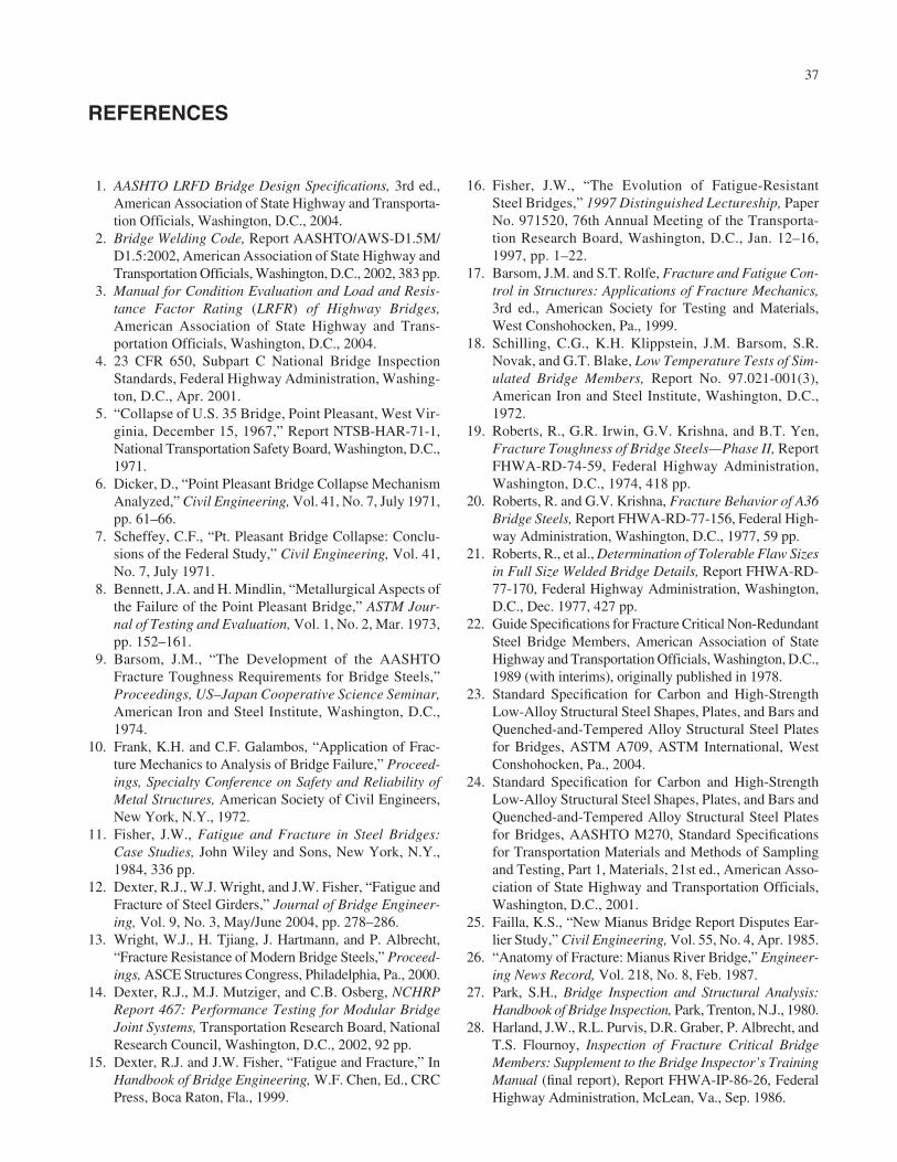
37
1. AASHTO LRFD Bridge Design Specifications, 3rd ed.,American Association of State Highway and Transporta-tion Officials, Washington, D.C., 2004.
2. Bridge Welding Code, Report AASHTO/AWS-D1.5M/D1.5:2002, American Association of State Highway andTransportation Officials, Washington, D.C., 2002, 383 pp.
3. Manual for Condition Evaluation and Load and Resis-tance Factor Rating (LRFR) of Highway Bridges,American Association of State Highway and Trans-portation Officials, Washington, D.C., 2004.
4. 23 CFR 650, Subpart C National Bridge InspectionStandards, Federal Highway Administration, Washing-ton, D.C., Apr. 2001.
5. “Collapse of U.S. 35 Bridge, Point Pleasant, West Vir-ginia, December 15, 1967,” Report NTSB-HAR-71-1,National Transportation Safety Board, Washington, D.C.,1971.
6. Dicker, D., “Point Pleasant Bridge Collapse MechanismAnalyzed,” Civil Engineering, Vol. 41, No. 7, July 1971,pp. 61–66.
7. Scheffey, C.F., “Pt. Pleasant Bridge Collapse: Conclu-sions of the Federal Study,” Civil Engineering, Vol. 41,No. 7, July 1971.
8. Bennett, J.A. and H. Mindlin, “Metallurgical Aspects ofthe Failure of the Point Pleasant Bridge,” ASTM Jour-nal of Testing and Evaluation, Vol. 1, No. 2, Mar. 1973,pp. 152–161.
9. Barsom, J.M., “The Development of the AASHTOFracture Toughness Requirements for Bridge Steels,”Proceedings, US–Japan Cooperative Science Seminar,American Iron and Steel Institute, Washington, D.C.,1974.
10. Frank, K.H. and C.F. Galambos, “Application of Frac-ture Mechanics to Analysis of Bridge Failure,” Proceed-ings, Specialty Conference on Safety and Reliability ofMetal Structures, American Society of Civil Engineers,New York, N.Y., 1972.
11. Fisher, J.W., Fatigue and Fracture in Steel Bridges:Case Studies, John Wiley and Sons, New York, N.Y.,1984, 336 pp.
12. Dexter, R.J., W.J. Wright, and J.W. Fisher, “Fatigue andFracture of Steel Girders,” Journal of Bridge Engineer-ing, Vol. 9, No. 3, May/June 2004, pp. 278–286.
13. Wright, W.J., H. Tjiang, J. Hartmann, and P. Albrecht,“Fracture Resistance of Modern Bridge Steels,” Proceed-ings, ASCE Structures Congress, Philadelphia, Pa., 2000.
14. Dexter, R.J., M.J. Mutziger, and C.B. Osberg, NCHRPReport 467: Performance Testing for Modular BridgeJoint Systems, Transportation Research Board, NationalResearch Council, Washington, D.C., 2002, 92 pp.
15. Dexter, R.J. and J.W. Fisher, “Fatigue and Fracture,” InHandbook of Bridge Engineering, W.F. Chen, Ed., CRCPress, Boca Raton, Fla., 1999.
16. Fisher, J.W., “The Evolution of Fatigue-ResistantSteel Bridges,” 1997 Distinguished Lectureship, PaperNo. 971520, 76th Annual Meeting of the Transporta-tion Research Board, Washington, D.C., Jan. 12–16,1997, pp. 1–22.
17. Barsom, J.M. and S.T. Rolfe, Fracture and Fatigue Con-trol in Structures: Applications of Fracture Mechanics,3rd ed., American Society for Testing and Materials,West Conshohocken, Pa., 1999.
18. Schilling, C.G., K.H. Klippstein, J.M. Barsom, S.R.Novak, and G.T. Blake, Low Temperature Tests of Sim-ulated Bridge Members, Report No. 97.021-001(3),American Iron and Steel Institute, Washington, D.C.,1972.
19. Roberts, R., G.R. Irwin, G.V. Krishna, and B.T. Yen,Fracture Toughness of Bridge Steels—Phase II, ReportFHWA-RD-74-59, Federal Highway Administration,Washington, D.C., 1974, 418 pp.
20. Roberts, R. and G.V. Krishna, Fracture Behavior of A36Bridge Steels, Report FHWA-RD-77-156, Federal High-way Administration, Washington, D.C., 1977, 59 pp.
21. Roberts, R., et al., Determination of Tolerable Flaw Sizesin Full Size Welded Bridge Details, Report FHWA-RD-77-170, Federal Highway Administration, Washington,D.C., Dec. 1977, 427 pp.
22. Guide Specifications for Fracture Critical Non-RedundantSteel Bridge Members, American Association of StateHighway and Transportation Officials, Washington, D.C.,1989 (with interims), originally published in 1978.
23. Standard Specification for Carbon and High-StrengthLow-Alloy Structural Steel Shapes, Plates, and Bars andQuenched-and-Tempered Alloy Structural Steel Platesfor Bridges, ASTM A709, ASTM International, WestConshohocken, Pa., 2004.
24. Standard Specification for Carbon and High-StrengthLow-Alloy Structural Steel Shapes, Plates, and Bars andQuenched-and-Tempered Alloy Structural Steel Platesfor Bridges, AASHTO M270, Standard Specificationsfor Transportation Materials and Methods of Samplingand Testing, Part 1, Materials, 21st ed., American Asso-ciation of State Highway and Transportation Officials,Washington, D.C., 2001.
25. Failla, K.S., “New Mianus Bridge Report Disputes Ear-lier Study,” Civil Engineering, Vol. 55, No. 4, Apr. 1985.
26. “Anatomy of Fracture: Mianus River Bridge,” Engineer-ing News Record, Vol. 218, No. 8, Feb. 1987.
27. Park, S.H., Bridge Inspection and Structural Analysis:Handbook of Bridge Inspection, Park, Trenton, N.J., 1980.
28. Harland, J.W., R.L. Purvis, D.R. Graber, P. Albrecht, andT.S. Flournoy, Inspection of Fracture Critical BridgeMembers: Supplement to the Bridge Inspector’s TrainingManual (final report), Report FHWA-IP-86-26, FederalHighway Administration, McLean, Va., Sep. 1986.
REFERENCES

29. Bridge Inspectors Reference Manual, FHWA NHI 03-002, Federal Highway Administration, Washington, D.C.,Oct. 2002.
30. Harper, J., “Underbridge Equipment,” Bridge Builder,Oct.–Dec. 2003, p. 25.
31. Zettler, R., “Crisis Averted,” Bridge Builder, Mar.–Apr.2004, pp. 24–26.
32. Hearn, G., et al., Bridge Management Systems, FederalHighway Administration, Washington, D.C., to bepublished.
33. Verma, K., et al., Steel Bridge Fabrication Technolo-gies in Europe and Japan, Report FHWA-PL-01-018,Federal Highway Administration, Washington, D.C.,Mar. 2003.
34. Ghosn, M. and F. Moses, NCHRP Report 406: Redun-dancy in Highway Bridge Superstructures, Trans-portation Research Board, National Research Council,Washington, D.C., 1998, 50 pp.
35. “Bridge Disasters in the United States,” CNN, May 26,2002 [Online]. Available: http://www.cnn.com/2002/US/05/26/bridge.accidents.
36. Fisher, J.W., A.W. Pense, and R. Roberts, “Evaluation ofFracture of Lafayette Street Bridge,” Journal of the Struc-tural Division, Vol. 103, No. 7, July 1977, pp. 1339–1357.
37. Connor, R.J., E.J. Kaufmann, J. Jin, and C.H. Davies,“Forensic Investigation of the SR422 Over the SchuylkillRiver Girder Fracture,” Proceedings of the Twenty-FirstInternational Bridge Conference, Pittsburgh, Pa., 2004.
38. Wright, W.J., J.W. Fisher, and B. Sivakumar, HoanBridge Failure Investigation, Federal Highway Admin-istration, Washington, D.C., 2001.
39. Harper, J. and S. Lender, “Emergency Fix,” BridgeBuilder, Oct.–Dec. 2003, pp. 26–28.
40. Idriss, R.L., K.R. White, C.B. Woodward, and D.V.Jauregui, “After-Fracture Redundancy of Two GirderBridge: Testing I-40 Bridges Over Rio Grande,” Con-ference Proceedings 7, Fourth International Bridge Engi-neering Conference, Aug. 28–30, 1995, San Francisco,Calif., pp. 316–326.
41. Kritzler, R.W. and J. Mohammadi, “Probabilistic Eval-uation of Redundancy of Bridge Structures,” Proceed-ings of the Sixth Specialty Conference, Denver, Colo.,July 8–10, 1992.
42. Moses, F., “Evaluation of Bridge Safety and Remain-ing Life,” Conference Proceeding, In Structural Design,Analysis, and Testing, Alfred H.S. Ang, Ed., 1989, pp.717–726.
38
43. Frangopol, D.M. and J.P. Curley, “Effects of Damageand Redundancy on Structure Reliability,” ASCE SpringConvention, Washington, D.C., Apr. 7–10, 1986.
44. Frangopol, D.M. and J.P. Curley, “Effects of Redun-dancy Deterioration on the Reliability of Truss Systemsand Bridges,” Conference Proceedings, In Effects ofDeterioration on Safety and Reliability of Structures,S. Marshall Ma, Ed., 1986.
45. Frangopol, D.M. and R. Nakib, “Redundancy Evalua-tion of Steel Girder Bridges,” 5th International Confer-ence on Structural Safety and Reliability, San Francisco,Calif., Aug. 7–11, 1989.
46. Frangopol, D.M. and K. Yoshida, “Loading and MaterialBehavior Effects on Redundancy,” Proceedings of Struc-tures Congress, Chicago, Ill., Apr. 15–18, 1996.
47. Heins, C. and C.K. Hou, “Bridge Redundancy: Effect ofBracing,” Journal of the Structural Division, Vol. 106,No. 6, June 1980, pp. 1364–1367.
48. Heins, C.P. and H. Kato, “Load Redistribution ofCracked Girders,” Journal of the Structural Division,Vol. 108, No. 8, Aug. 1982, pp. 1909–1915.
49. Elza, P., T. Shkurti, and K. Price, “Redundancy Analy-sis,” Marquette Interchange Final Design, MilwaukeeTransportation Partners, Milwaukee, Wis., Mar. 2004.
50. Lai, L.L.-Y., “Impulse Effect on Redundancy of a Tied-Arch Bridge,” Computing in Civil Engineering, Proceed-ings of the First Congress held in conjunction with A/E/CSystems ‘94, Washington, D.C., June 20–22, 1994.
51. Michael Baker, Jr., Inc., “Investigation of Tie BeamRedundancy,” July 10, 2003.
52. Dexter, R.J., S.A. Altstadt, and C.A. Gardner, “Strengthand Ductility of HPS70W Tension Members and TensionFlanges with Holes,” Final Report to American Iron andSteel Institute, University of Minnesota, Twin Cities,Mar. 2002.
53. Dexter, R.J. and S.A. Altstadt, “Strength and Ductilityof Tension Flanges in Girders,” Recent Developmentsin Bridge Engineering, K.M. Mahmoud, Ed., A.A.Balkema/Swets & Zeitlinger, Exton, Pa., Oct. 2003,pp. 67–81.
54. Manual for Condition Evaluation of Bridges, 2nd ed.,American Association of State Highway and Trans-portation Officials, Washington, D.C., 2000, 148 pp.
55. Warne, T.R., NCHRP Synthesis of Highway Practice313: State DOT Outsourcing and Private-Sector Utiliza-tion, Transportation Research Board, National ResearchCouncil, Washington, D.C., June 2003, 42 pp.

39
OVERVIEW OF FATIGUE
Fatigue is considered a serviceability limit state for bridges.This is because fatigue cracks do not typically compromisestructural integrity and are more of a maintenance issue.However, as was recognized by the Task Committee onRedundancy of Flexural Systems (A1), fatigue is the mostcommon cause of reported damage in steel bridges.
The fatigue design and assessment procedures outlined inthis appendix are included in the AASHTO specifications forbridges (A2). As a result, steel bridges that have been built inthe last two decades have not and should not have any signifi-cant problems with fatigue and fracture (A3). However, bridgesdesigned before the modern specifications will continue to besusceptible to the development of fatigue cracks and to fracture.
Detailing rules are perhaps the most important part of thefatigue and fracture design and assessment procedures.These rules are intended to avoid notches and other stressconcentrations, as well as the use of details known to be veryfatigue sensitive. They also often result in details that haveimproved resistance against brittle fracture as well as fatigue.Modern steel bridges are also detailed in a way that appearsmuch cleaner than those built before the 1970s. There arefewer connections and attachments in modern bridges andthe connections use more fatigue-resistant details, such ashigh-strength bolted joints.
In bridges there are usually a large number of cycles of sig-nificant live load and fatigue will almost always precede frac-ture. Therefore, controlling fatigue is practically more impor-tant than controlling fracture. Usually, the only measures takenin design that are primarily intended to ensure fracture resis-tance are those to specify materials with minimum specifiedtoughness values [such as a Charpy V-notch (CVN) test re-quirement]. As explained in chapter three, toughness is speci-fied so that the structure is resistant to brittle fracture despitemanufacturing defects, fatigue cracks, and/or unanticipatedloading. However, these material specifications are less impor-tant for bridges than the S–N curves and detailing rules.
Nominal Stress S–N Curves
The established method for fatigue design and assessment ofsteel bridges in the United States is the nominal stress approach.The nominal stress approach is based on S–N curves, where Sis the nominal stress range and N is the number of cycles untilthe appearance of a visible crack. Details are designed based on
APPENDIX A
Background Discussion on Fatigue, Fracture, Nondestructive Evaluation,and Repair and Retrofit
the nominal stress range in the connecting members rather thanthe local “concentrated” stress at the detail. The nominal stressis usually obtained from standard design equations for bendingand axial stress and does not include the effect of stress con-centrations of welds and attachments. AASHTO (A2) has sevenS–N curves corresponding to seven categories of weld details(A through E’), as shown in Figure A1.
The fatigue design procedure is based on associating theweld detail under consideration with a specific category. Theeffects of the welds and other stress concentrations, includ-ing the typical defects and residual stresses, are reflected inthe ordinate of the S–N curves for the various detail cate-gories. Consequently, the variability of fatigue life data at aparticular stress range is typically about a factor of 10.
The AASHTO S–N curves in Figure A1 are also usedthroughout North America for a variety of other weldedstructures, including the American Institute for Steel Con-struction Manual of Steel Construction (A4), the AmericanRailway Engineering and Maintenance-of-Way AssociationManual for Railway Engineering (A5), the American Weld-ing Society (AWS D1.1) Structural Welding Code (A6), andthe Canadian Standards Association (CSA S16-2001) LimitStates Design of Steel Structures (A7).
The S–N curves can be represented by the following powerlaw relationship:
where N is the number of stress cycles, S is the nominal stressrange, and A is a constant particular to the detail category, asgiven in Table A1.
In the nominal stress range approach, each detail categoryalso has a constant-amplitude fatigue limit (CAFL), which isgiven in Table A1. The CAFL is the stress range below whichno fatigue cracks occurred in tests conducted with constant-amplitude loading.
The approach to designing and assessing bridges forfatigue is empirical and is based on tests of full-scale mem-bers with welded or bolted details. Such tests indicate that:
• The strength and type of steel have only a negligibleeffect on the fatigue resistance expected for a particulardetail (A8–A10).
• The welding process also does not typically have aneffect on the fatigue resistance (A11,A12).
NA
S=
31( )
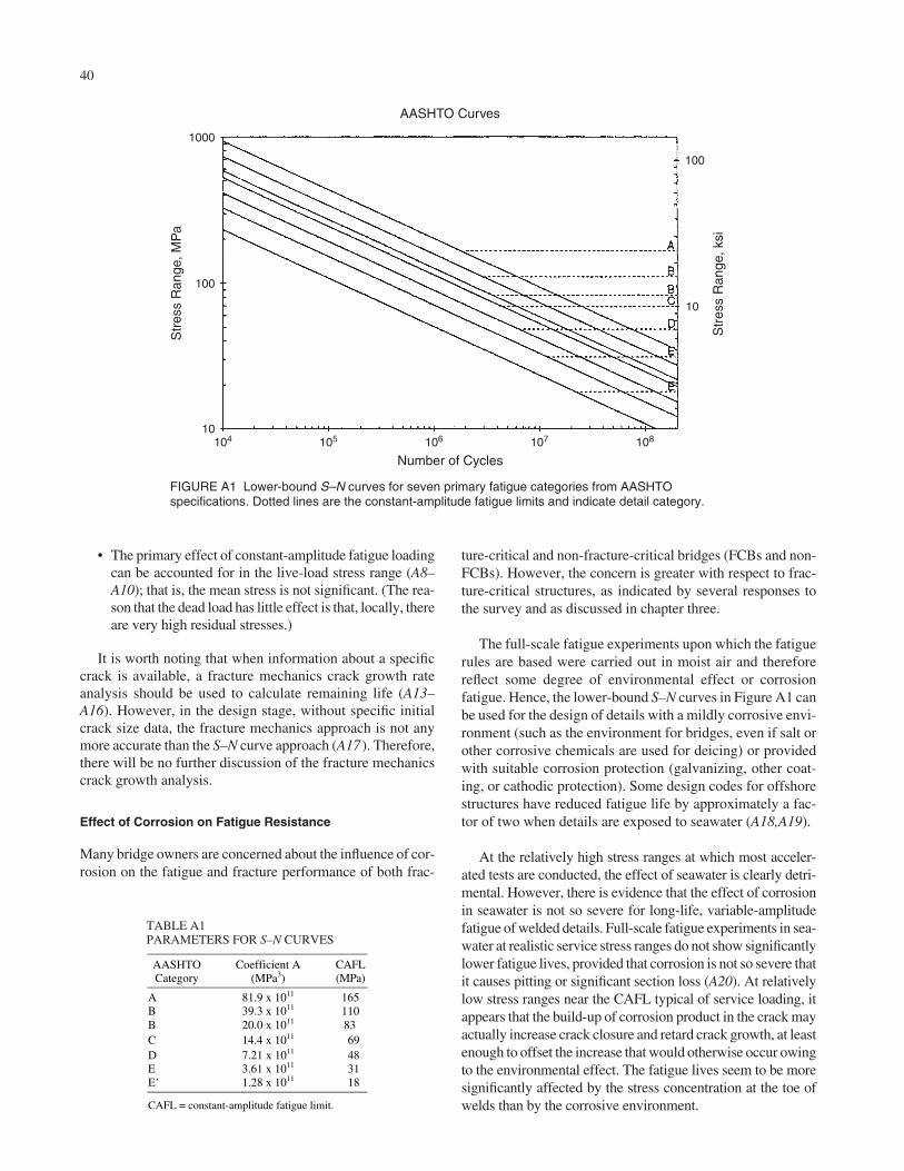
• The primary effect of constant-amplitude fatigue loadingcan be accounted for in the live-load stress range (A8–A10); that is, the mean stress is not significant. (The rea-son that the dead load has little effect is that, locally, thereare very high residual stresses.)
It is worth noting that when information about a specificcrack is available, a fracture mechanics crack growth rateanalysis should be used to calculate remaining life (A13–A16). However, in the design stage, without specific initialcrack size data, the fracture mechanics approach is not anymore accurate than the S–N curve approach (A17). Therefore,there will be no further discussion of the fracture mechanicscrack growth analysis.
Effect of Corrosion on Fatigue Resistance
Many bridge owners are concerned about the influence of cor-rosion on the fatigue and fracture performance of both frac-
40
ture-critical and non-fracture-critical bridges (FCBs and non-FCBs). However, the concern is greater with respect to frac-ture-critical structures, as indicated by several responses tothe survey and as discussed in chapter three.
The full-scale fatigue experiments upon which the fatiguerules are based were carried out in moist air and thereforereflect some degree of environmental effect or corrosionfatigue. Hence, the lower-bound S–N curves in Figure A1 canbe used for the design of details with a mildly corrosive envi-ronment (such as the environment for bridges, even if salt orother corrosive chemicals are used for deicing) or providedwith suitable corrosion protection (galvanizing, other coat-ing, or cathodic protection). Some design codes for offshorestructures have reduced fatigue life by approximately a fac-tor of two when details are exposed to seawater (A18,A19).
At the relatively high stress ranges at which most acceler-ated tests are conducted, the effect of seawater is clearly detri-mental. However, there is evidence that the effect of corrosionin seawater is not so severe for long-life, variable-amplitudefatigue of welded details. Full-scale fatigue experiments in sea-water at realistic service stress ranges do not show significantlylower fatigue lives, provided that corrosion is not so severe thatit causes pitting or significant section loss (A20). At relativelylow stress ranges near the CAFL typical of service loading, itappears that the build-up of corrosion product in the crack mayactually increase crack closure and retard crack growth, at leastenough to offset the increase that would otherwise occur owingto the environmental effect. The fatigue lives seem to be moresignificantly affected by the stress concentration at the toe ofwelds than by the corrosive environment.
AASHTO Curves
1000
100
10
100
10
104 105 106 107 108
Number of Cycles
Str
ess
Ran
ge, M
Pa
Str
ess
Ran
ge, k
si
FIGURE A1 Lower-bound S–N curves for seven primary fatigue categories from AASHTOspecifications. Dotted lines are the constant-amplitude fatigue limits and indicate detail category.
AASHTOCategory
CAFL(MPa)
A 165B 110Bí 83C 69D 48E 31E’
Coefficient A(MPa3)
81.9 x 10¹¹
39.3 x 10¹¹
20.0 x 10¹¹
14.4 x 10¹¹
7.21 x 10¹¹
3.61 x 10¹¹
1.28 x 10¹¹ 18
CAFL = constant-amplitude fatigue limit.
TABLE A1PARAMETERS FOR S–N CURVES

41
Severely corroded members may be evaluated as CategoryE details (A21), regardless of their original category (unlessof course they were Category E′ or worse to start with). How-ever, pitting or significant section loss from severe corrosioncan also lower that fatigue strength (A21,A22).
Loading for Fatigue Design
It is important to note that the load producing fatigue crackingis comprised of the entire load spectrum crossing the bridge.The load that produces a fracture, on the other hand, is typi-cally the largest load from the load spectrum. Bridges experi-ence what is known as long-life, variable-amplitude loading[i.e., very large numbers of random amplitude cycles greaterthan the number of cycles associated with the CAFL (A23)].
If the percentage of stress ranges exceeding the CAFL isgreater than approximately 0.01%, the history of N variablestress ranges can be converted to N cycles of an effective stressrange that can then be used just like a constant-amplitude stressrange in S–N curve analysis. Typically, Miner’s rule (A24) isused to calculate an effective stress range from a histogram ofvariable stress ranges. Theoretically, this effective constant-amplitude stress range results in approximately the samefatigue damage for a given number of cycles as the same num-ber of cycles of the variable-amplitude service history. If thestress ranges are counted in discrete “bins,” as in a histogram,the effective stress range, SRe (A23), can be calculated as:
where αi = number of stress cycles with stress range in thebin with average value Sri divided by the total number ofstress cycles (N).
In the AASHTO specifications (A2), the stress range fromthe fatigue design truck (i.e., the HS15) represents the effec-tive stress range. No additional safety factor is used forMiner’s rule, because it is relatively accurate for truck loadingon bridges. For large numbers of cycles, the AASHTO speci-fication has another check that involves comparing the stressrange from the fatigue design truck with one-half of the CAFL.This check is actually intended to compare the CAFL with astress range that is twice that produced by the fatigue designtruck (i.e., dividing the resistance by two is the same as multi-plying the load by two). Although somewhat confusing inapplication, the intent is to ensure that almost all of the stressranges should be below the CAFL, but that occasionally thestress range can exceed the CAFL with no significant effect.
Fatigue Life Prediction Methodology for Existing Bridges
The 1990 AASHTO Guide Specifications for the FatigueEvaluation of Existing Steel Bridges (A25) can be used for thefatigue evaluation of steel bridges. The purpose of the guide
S Si rii
Re ( )= ( )( )∑ α 31 3
2
is to provide procedures for calculating the remaining fatiguelife of existing steel bridges using concepts of probabilisticlimit states. The fatigue evaluation procedures in the guidewere adopted from and are identical to the proposed proce-dures presented in NCHRP Report 299: Fatigue EvaluationProcedures for Steel Bridges (A26). The effects of repeatedloading on the fatigue life of an existing bridge are defined interms of the remaining life of the structure. This means thatthe effect of exceeding the allowable fatigue stress is a reduc-tion of the remaining fatigue life of the structure rather thanimmediate failure.
There are two levels for which the remaining fatigue lifecan be calculated, the remaining safe life and the remainingmean life. The remaining safe life provides a much higherlevel of safety. The safe life has an exceedence probability of97.7% for redundant members (the same probability inherentin using the basic design S–N curves). The mean remaininglife, however, is the best estimate of the actual remainingfatigue life of the detail under consideration. The mean lifehas an exceedence probability of 50%.
The safe life is used for design and for a first screeninganalysis. The impact of reaching a safe life equal to zeroshould be relatively minimal; it may mean having to repairjust a small percentage of the details on a bridge. In this case,the calculated mean life may be used to determine when the cracking will be so pervasive that half the details will be cracking, requiring extensive retrofitting or possiblyreplacement of the bridge. If the remaining life that is esti-mated is not satisfactory, there are four options: (1) recalcu-late the fatigue life more accurately (possibly using load test-ing), (2) restrict truck traffic on the bridge, (3) repair or modifythe detail, and/or (4) perform more frequent inspections ofthe detail.
The procedures in NCHRP Report 299 (A26) are the bestavailable procedures for predicting the number of yearsbefore substantial fatigue cracking may occur at a detail. It isdifficult to accurately predict all of the variables that thebridge will experience over its remaining life, such as past,present, and future truck volumes and stress ranges, whichcan also vary with changing truck weights over time.
Although calculations are by far the most common andfavored methods of estimating remaining fatigue life in abridge, they are also the least accurate. Field instrumenta-tion and monitoring has consistently demonstrated that mea-sured in-service stress range histograms result in the mostaccurate estimates of remaining life. Analysis methods relyon approximate load models and simplified structural analy-sis models, both of which are typically conservative. Mea-surements made in the field reflect actual site conditions andtraffic patterns when recorded over a sufficient period oftime. Because the stress range is directly measured at thedetail in question, there is no error introduced through ana-lytical simplifications.

Because in nearly all cases field measurements indicatethat in-service stresses are less than predicted, costly retrofitscan be eliminated or reduced in number. The resulting sav-ings will almost always far exceed the cost of the additionalefforts associated with the field instrumentation. Despite thispotential for savings, most agencies do not use this approach,as will be discussed in the review of the survey results.
OVERVIEW OF FRACTURE
Fracture may be defined as rupture in tension or rapid exten-sion of a crack, leading to gross deformation, loss of functionor serviceability, or complete separation of the component(A4,A14,A27). Because the scope of this synthesis is limitedto practical information, there are many interesting aspects offracture that are not discussed. However, there are severalgood texts that can serve as a starting point for more in-depthstudies (A14,A15,A27).
It is important to rapidly assess the potential for fracturewhenever there is a crack in any tension element (tensionmember or tension flange of flexural member). However, theoccurrence of fatigue cracks does not necessarily mean thatthe structure is in danger (A13,A27). In some redundantstructures, a fatigue crack may stop propagating with nointervention at all as a result of redistribution of stresses(A28). Usually, however, a fatigue crack will propagate andeventually cause a fracture if not repaired in a timely manner(A13,A15,A27). The development of a fatigue crack in a frac-ture-critical member (FCM) should, in most cases, warrantclosure of one or more lanes, posting the bridge for cars only,or result in complete closure of the bridge until repairs canbe made. Fracture is the rupture in tension or rapid extensionof a crack leading to gross deformation, loss of function orserviceability, or complete separation of the component.
Details that have good fatigue resistance, Category C andbetter, are usually also optimized for resistance to fracture.Detailing rules to avoid fracture are very similar to thecommon sense rules to avoid fatigue. For example, inter-secting welds should always be avoided owing to the proba-bility of defects and excessive constraint. Intersecting welds,or even welds of too close proximity, have caused brittlefractures [e.g., the Hoan Bridge in Wisconsin (A29) and theSR-422 bridge in Pennsylvania (A30,A31)]. Weld backingbars must usually be removed to achieve the needed resis-tance to both fatigue and fracture. Stress concentrations suchas reentrant corners should be avoided and instead transitionradii that are ground smooth and flush should be provided.This commonly occurs at copes in floorbeams at connectionsdesigned for vertical shear only.
The ends of butt welds are always a potential location ofdefects. It is important to use run-out tabs and to later grindthe ends of the weld flush or to a radius. Fillet weld termina-tions should not be ground, for this will expose a very thinligament near the weld root that will tear easily.
42
Fracture Assessment Procedures
A fracture assessment is made using fracture mechanics prin-ciples (A13–15,A32,A33). In the absence of other establishedprocedures, an often used reference is the 1999 British Stan-dard, BS 7910, “Guide on Methods for Assessing theAcceptability of Flaws in Metallic Structures” (A32). Thereis presently no comparable U.S. standard; however, BS 7910is used by some U.S. industries (primarily the oil and gasindustries).
A fracture assessment requires some knowledge of thefracture toughness of the steel and/or weld metal, which maybe estimated from the Charpy energy or CVN (A15,A33).Unlike fatigue, the susceptibility to fracture is stronglydependent on the type of material and even the particular heatof the steel or lot of weld metal (A14,A15,A34,A35). TheCVN may be obtained from mill reports for the steel andfrom the certifications for the weld metal, if good recordsexist. Lacking such specific information, for bridges builtsince 1974 when minimum Charpy requirements were firstincluded in the ASTM A709 specification for bridge steels,the CVN for the steel plate and weld metal may be assumedto be at least as large as the minimum specified values. Forolder structures, or for cases when the assumed minimumvalues are not sufficient, it may be necessary to drill a coreand get a sample of the steel, then make and test some Charpyspecimens. A minimum of three specimens should be testedfrom each plate or structural shape. The fracture assessmentwill not be discussed further because it is documented else-where and is not the emphasis of this report.
Causes for Fracture Other Than Fatigue
As mentioned previously, fracture in bridges is almost alwaysa result of fatigue cracking. However, if a detail and materialare particularly susceptible to fracture, failure will usuallyoccur as the loads are applied for the first time during or soonafter construction. An example is the fracture that occurredwhen the Caltrans Workers Memorial Bridge (previouslyknown as the Bryte Bend Bridge) was under construction in1970. The fracture, shown in Figure A2, was attributed to useof low-toughness A514 steel (A36) at a point where a trans-verse bracing member was welded along the edge of the pri-mary tension flange of a tub girder, creating a stress concen-tration at the reentrant corner. A514 steel, marketed under thename of T1 steel, is quenched and tempered with a minimumspecified yield stress of 690 MPa.
It is also possible that fracture can occur in service directlywithout apparent fatigue crack growth. For example, at poordetails that are highly constrained, such as the intersection pointof two or three welds, fracture may occur in service directlyfrom small crack-like weld discontinuities, such as the fracturesthat originated at shelf plate details in the Hoan Bridge in Mil-waukee in December 2000 (A29) (Figure A3) or the SR-422failure (A30,A31). Repair and retrofit of these shelf-plate details

43
are discussed in special directives from FHWA and are not dis-cussed further in this report.
Subcritical crack propagation in bridge elements may alsooccur by stress corrosion cracking (SCC), although this is aconcern only for very-high-strength steels; that is, steel withyield strength much greater than 100 ksi. SCC involves elec-trochemical dissolution of metal along active sites under the
influence of tensile stress (A14,A15). As hydrogen is liber-ated in the process, this failure mechanism may also involvehydrogen cracking. SCC can be distinguished from fatiguecracking by examining the fracture surface under a lightmicroscope. SCC has occurred in prestressing cables (A37)and in A490 bolts that were out of specification (A38).
Specification of Charpy V-Notch for Fracture Resistance
Fracture behavior depends strongly on the type and strengthlevel of the steel or filler metal. The fracture resistance ofeach type of steel or weld metal varies significantly from heatto heat, or from lot to lot. Although fracture toughness can bemeasured directly in fracture mechanics tests (A14–A16), theusual practice is to characterize the toughness of steel interms of the impact energy absorbed by a CVN specimen(A15). Because the Charpy test is relatively easy to do, it willlikely continue to be the measure of toughness used in steelspecifications.
Because it is not directly related to the fracture toughness,CVN energy is often referred to as notch toughness. Thenotch toughness is still very useful, however, because it canoften be correlated to the fracture toughness and then used ina fracture mechanics assessment (A15,A32,A33). Figure A4shows a plot of the CVN energy of A709 Grade 50 (350 MPayield strength) structural steel at varying temperatures. Theseresults are typical for ordinary hot-rolled structural steel.
The fracture limit state includes phenomena ranging fromthe brittle fracture of low-toughness materials at service loadlevels to ductile tensile rupture of a component. The transi-tion between these phenomena depends on temperature, asreflected by the variation of CVN with temperature as shownin Figure A4. The transition is a result of changes in theunderlying microstructural fracture mode.
Brittle fracture on the so-called lower shelf in Figure A4is associated with cleavage of individual grains on selectcrystallographic planes. Brittle fracture may be analyzedwith linear-elastic fracture mechanics theory because theplastic zone at the crack tip is very small. At the high end ofthe temperature range, the so-called upper shelf, ductile frac-ture is associated with the initiation, growth, and coalescenceof microstructural voids, a process requiring much energy.The net section of plates or shapes fully yields and then rup-tures with large slanted shear lips on the fracture surface.
Transition-range fracture occurs at temperatures betweenthe lower and upper shelves and is associated with a mixtureof cleavage and shear fracture. Large variability in toughnessat constant temperature and large changes of temperature aretypical of transition-range fractures.
AASHTO specifications for bridge steel and weld fillermetal require minimum CVN values at specific temperatures
FIGURE A2 Brittle fracture of flange of tub girder of Bryte BendBridge in Sacramento, California, while under construction.
FIGURE A3 Fractured girder of the Hoan Bridge in Milwaukee(top) and view of critical shelf plate detail featuring intersectingwelds.

(A25). As shown in Figure A4, the typical lower-shelf CVN isabout 10 J. Therefore, when a minimum CVN of 20 J or moreis specified at some temperature, the most important result ofsuch a specification is that the lower shelf of the Charpycurve will start at a temperature lower than the specified tem-perature. This indicates that the lower shelf of a structureloaded statically or at intermediate strain rates such as trafficloading on a bridge is even lower, a phenomena known as thetemperature shift (A15). Because of the temperature shift, thetemperature at which the CVN requirement is specified maybe greater than the lowest anticipated service temperature.
If the material is not on the lower shelf at service tempera-ture, brittle fracture will not occur as long as large cracks donot develop. It essentially does not matter what the specifiedCVN value is as long as it is at least 20 J. Usually, an averagefrom three tests of 34 J (25 ft-lbs) or 27 J (20 ft-lbs) is speci-fied at a particular temperature. The greater the value of theaverage CVN requirement, the more certain that the material
44
is well above the lower shelf; however, there may be a greaterpremium to be paid with diminishing increases in certainty.
Table A2 lists, as an example, values of impact energypresently required for base metal in FCMs for the three tem-perature zones into which the United States is divided. [Fornonfracture-critical members (non-FCMs), typically only 20J is required at the same temperatures.] The complete table isfound in the LRFD Specifications (A2). For example, 50-mmthick flange plates of grade 345W steel for an FCB to be builtat a site where the lowest anticipated service temperature(LAST) is −15°C must have the minimum impact energy forZone 1, which is 34 J at 21°C.
History of Development of the Fracture Critical Plan
The fracture toughness requirements are based on a correla-tion between the fracture toughness in terms of the stress-
TEST TEMPERATURE, °F
A588 19mm PlateCharpy Data
0 50 100 150 200 250-50-100-150
0
10
30
50
70
20
40
6090
25 50 75 100-25-50-75
TEST TEMPERATURE, °C
CV
N, J
oule
s
CV
N, f
t-lb
FIGURE A4 Charpy energy transition curve for A709 Grade 50 (350 MPa yieldstrength) structural steel.
ASTM A709Steel Grade
Plate Thickness (mm) and
Joining Methoda
Zone 1 LAST = −18°C (Joules at °C)
Zone 2 LAST = −34°C (Joules at °C)
Zone 3 LAST = −51°C (Joules at °C)
250F Up to 100 M & W 34 at 21 34 at 4 34 at −12
Up to 50 M & W 34 at 21 34 at 4 34 at −12
Over 50 to 100 M 34 at 21 34 at 4 34 at −12 345F, 345WF
Over 50 to 100 W 41 at 21 41 at 4 41 at −12
HPS-485WF Up to 100 M & W 48 at −23 48 at −23 48 at −23
Up to 65 M & W 48 at −1 48 at −18 48 at −34
Over 65 to 100 M 48 at −1 48 at −18 48 at −34
690F, 690WF Over 65 to 100 W 68 at −1 68 at −18 Not permitted
aM = mechanically fastened; W = welded.
TABLE A2MINIMUM CHARPY IMPACT TEST REQUIREMENTS FOR FRACTURE-CRITICAL MEMBERS

45
intensity factor and the CVN, including a “temperatureshift.” The temperature shift accounts for the differences instrain rate between the Charpy impact test and the trafficloads. For example, the time it takes to reach the yield strainin bridges from an overloaded truck is about one second ver-sus one millisecond in the Charpy test (A15). Several inde-pendent studies verified the temperature shift (A39–A41).
For example, several girders were tested at the U.S. SteelResearch Laboratory that contained fatigue cracks initiated atthe ends of cover plate details (A41). A more extensive studywas done at Lehigh University that examined an increasednumber of specimens fabricated from grade 250, 345, and 690steels (A39). In both studies, the fatigue cracks were grown attemperatures and loading rates that closely resemble thoseencountered in bridges, and the cracked girders were sub-jected to periodic overloads until fracture occurred.
The temperature shift was the subject of some disagreementin the development of notch toughness requirements in theearly 1970s. The prevailing opinion in the debate was thatordinary hot-rolled mild structural steels had sufficient notchtoughness. The specified CVN values are the typical minimumvalues that could be consistently achieved. Having the speci-fication was very important to screen out unusually brittlematerials.
Roberts and Krishna (A39) and Roberts et al. (A40),among others, argued that the fracture-critical specificationshould require a level of dynamic toughness sufficient toarrest pop-in-type fractures occurring from local brittle zones.Hartbower (A42) proposed an alternate fracture control planthat called for the CVN test to be done at the same tempera-tures as the LAST for the bridge service site; that is, withoutexploiting the benefit of the temperature shift. This wouldmean that CVN would be required at −34°C for Zone II (mostof the country). To achieve notch toughness at these lowertemperatures, the steel would require additional processing,such as normalization. This increased processing would sig-nificantly increase the cost of the steel, which is a major partof total bridge costs.
Ultimately, the temperature shift concept was retained,largely out of economic necessity, and the fracture controlplan placed a strong emphasis on defect control to preventthe pop-in-type fracture events. Therefore, the CVN require-ments represented a compromise that allowed the continueduse of hot-rolled steel rather than normalized steel.
The good fracture-resistance track record of mild steelshows that requiring normalized steel would have been unnec-essary. Experience in service and in full-scale experiments hasverified the temperature shift and the adequacy of the notch-toughness requirements for mild steels. Some premature cracksand fractures occurred in tied arches fabricated with A514steel. A514 steel is quenched and tempered steel with a mini-mum specified yield stress of 100 ksi. This steel is much dif-
ferent than mild steel and should be avoided for FCMs. Frac-tures that occurred during construction in the box girders of theBryte Bend Bridge in California also occurred in A514 steel.Consequently, higher CVN requirements are implemented forthe higher strength steel, as shown in Table A2.
Again a compromise was reached, which resulted in theslightly increased CVN for FCMs at the same temperatureshift. At the same time, more stringent fabrication rules wereapplied for FCMs to control the possibility of initial defects.Most importantly, the stress range for fatigue design wasarbitrarily dropped by about one category, which resulted ina decrease in the allowable stress range of approximately25% in most cases. A 25% decrease in the stress range shouldessentially double the fatigue life. It is important to realizethat this decrease in the allowable stress range for FCMs inthe Standard Specifications has been dropped in the mostrecent LRFD Specifications (A2).
The Bridge Welding Code D1.5 calls for higher impactenergies in weld metal than in base metal, a reasonablerequirement given that the welds create stress raisers andhigh-tensile residual stresses. Given that the cost of fillermetal is relatively small in comparison with the overall costof materials, it is well worth specifying high-toughness fillermetal to mitigate the effects of high-tensile stresses inducedby welding. For FCMs, 34 J is required at −29°C for weldmetal, regardless of the temperature zone. For non-FCMs,weld metal is required that can give 27 J at −29°C for Zone3, and at −18°C for Zones 1 and 2.
The somewhat higher toughness requirements shown inTable A1 for thick plates that are to be welded is the result ofthe higher degree of constraint and plane–strain behavior attemperatures higher than would be the case for thinner plates.This is more of a problem in welded members, because weld-ing increases the potential for initial flaws and defects thatcan initiate brittle fracture. Another feature of the specifica-tion requires higher toughness for steels with yield strengthgreater than 345 MPa.
The AASHTO material toughness specifications providethe minimum level of toughness required to sufficiently min-imize the risk of brittle fracture. The existing AASHTO frac-ture control plan has generally done a good job of preventingfracture failure in bridge structures since design using its pro-visions. A few brittle fractures have still occurred withoutnoticeable fatigue crack growth in previously designed bridges,however, although the steel met the modern CVN toughnessrequirements (i.e., those required by the fracture control planor general AASHTO toughness requirements). In most suchcases, the fracture can be traced back to one or more aspectsof the fracture control plan related to controlling the size ofdefects. If all aspects of the fracture control plan are properlyimplemented, the risk of brittle fracture is minimized by thecurrent specifications and fracture will be a rare event in ser-vice. However, in the ensuing decades, very few FCBs were

constructed, in part because the fabrication costs were signif-icantly greater.
High-Performance Steel
The recently developed high-performance steels (HPS) aremuch tougher but also more expensive than the ordinaryGrade 250, 345, or 345W steel. The first grade to be fullyintegrated into the AASHTO specifications is the HPS485W. Two additional steels are currently being developed,an HPS 690 W Cu-Ni and an HPS 345W. Both of these steelsare much tougher than the ordinary Grade 250, 345, and345W steels. The main reason for developing HPS has beento improve weldability, but a large gain in toughness hasbeen a desirable by-product. Development of HPS in theUnited States has been done under a joint research and devel-opment program by FHWA, U.S. Navy, and the AmericanIron and Steel Institute (A43).
In contrast to ordinary bridge steel, Grade HPS 485W showsupper shelf behavior at test temperatures down to approxi-mately −20°C. Even at the extremely cold service temperaturefor Zone 3 (LAST = −51°C), this steel exhibits toughness in theupper transition region; without the benefit of the temperatureshift, the CVN energy still exceeds 150 J. Likewise, highdynamic and crack arrest toughness can be expected of thissteel. Clearly, HPS 485W steel provides a level of toughnessfar exceeding the current requirements, which are based on pre-venting brittle fracture.
In current research underway at the Turner–Fairbank High-way Research Center of FHWA, the fracture toughness of HPSare being determined as a function of temperature, loading rate,and plate thickness (A44,A45). At the same time, the fractureresistance of fatigue-cracked I-girders fabricated from HPS 485is being determined. The test girders are cyclically loaded untila crack grows to the desired length; the girder is then cooled to−34°C and subjected to a typical design overload. If the girderdoes not fracture, the fatigue crack is grown larger and the sameoverload is reapplied. The HPS 485W steel girder resisted thefull design overload until approximately 50% of the tensionflange area was lost to fatigue, meaning that the net section ofthe cracked tension flange had yielded.
In contrast, the full-scale tests discussed previously (A39,A41) on girders made of Grade 345 steel fractured when the netsection of the cracked tension flange reached a stress of approx-imately 60% of the yield stress, meaning that the fracture wasbrittle. In contrast, the fracture mode for the Grade HPS 485Windicates a large amount of plastic deformation before failure.
The HPS grade steels provide a toughness level that farexceeds the minimum requirements cited in Table A2.Although HPS 485W costs more than ordinary grade 345Wsteel, the advantages afforded by higher strength more thanoffset the difference in material costs. This has significantlyaltered the economic factors that were considered in setting
46
the current AASHTO toughness requirements. The cost pre-mium for higher toughness is lower than it was 30 years ago.
Consideration of Increasing ToughnessRequirements for Bridge Steel
Fortunately, today’s scrap-based steel typically has improvedtoughness relative to the steel of the 1970s. This is the resultof: (1) a reduction in carbon, (2) a reduction in impuritiessuch as phosphorous and sulfur, as well as (3) an increase inalloying elements such as nickel and chromium, whichenhance toughness. Nickel and chromium and other beneficialalloys just happen to be in the scrap that is derived primarilyfrom automobiles and other sheet metal, which tends to havegreater alloying than structural steel made from iron ore.
Because steel today has greater toughness than the steelsof the 1970s is perhaps the best argument for increasing thenotch toughness requirements for FCMs. This would allowdesigners to take advantage of the superior toughness char-acteristics of HPS (A45). In other words, because the CVNspecifications were essentially just below what was consis-tently attainable in the 1970s, and because the toughness hasgenerally improved over time, it is rational to raise the barsomewhat to ensure that the bridge steel represents the bestpractice of today. This could probably be done without forc-ing the mills to use any additional processing and thereforewould not significantly affect the cost of steel. Even though theargument can be made that the increased toughness is notabsolutely necessary, it is always better to have greater tough-ness if there is no cost penalty.
If there was no temperature shift, extremely large cracks,greater than 350 mm, can be tolerated in mild steel. If the notchtoughness requirements were increased, the increased tough-ness could also be used to offset the decrease in reliabilityassociated with no longer decreasing the stress range for FCMsin the LRFD Specifications (A2). To make it more palatable,this increase could be combined with some loosening of thedefinition of FCMs that would, for example, allow two-girderbridges that are known to be redundant, as discussed earlier.
Research currently underway at FHWA’s Turner–FairbankHighway Research Center is studying ways of taking advan-tage of the benefits of higher toughness as in most modern platesteel, especially HPS. These benefits include:
• Elimination of special in-service inspection require-ments, such as hands-on or arms-length inspection forfracture-critical structures for HPS.
• Reduction in the frequency of inspections for the super-structure components of HPS bridges.
• Elimination of the penalty for structures with low redun-dancy for HPS.
Ultimately, the greatest benefit might be achieved by pro-viding a solid foundation for structural innovation. The cur-

47
rent U.S. practice of providing a high level of structural redun-dancy prevents engineers from considering other structuralsystems that can result in more efficient, lower-cost bridges.For example, two-girder and tied-arch bridges are rarely builttoday in the United States, even though experience hasshown that in many situations they are very economical. Ahigher factor of safety against fracture will increase the reli-ability level of low-redundancy systems, thereby reducingthis barrier to innovation.
Although higher toughness makes bridges more tolerantto longer cracks, it does not significantly increase fatigue life.Fatigue cracks grow according to a power law; therefore,most of the fatigue life is spent growing the crack while it isvery small. Additional fracture toughness, greater than theminimum specified values, will allow the crack to growlonger before the member fractures. But, at that late stage, thecrack is growing so rapidly that relatively few cycles areneeded to reach the end of the life.
Ultimately, decisions to specify toughness beyond theminimum required level must be made based on cost. Thecurrent AASHTO steel toughness requirements were devel-oped using the cost factors that existed in the 1970s and con-sidering the state of the art in steel production at that time.Modern steel processing practice has made it more econom-ical to produce high-toughness steels such as A709 HPS485W. In addition, the Grade 250, 345, and 345W steels pro-duced today have typical CVN that far exceed the minimumrequirements. The current AASHTO specifications for mater-ial toughness may need to be reevaluated to take maximumadvantage of the higher-toughness steels used today.
INSPECTION AND NONDESTRUCTIVE TESTING
Periodic in-service inspection provides a final safety net todetect cracks before they grow to a critical size. Because ofthe repetition of details in a bridge, when one crack is found,it is very likely that similar details may also be cracked.Therefore, the first and most urgent step in planning repairsand retrofits is to thoroughly inspect the bridge for othercracks, usually visually but often followed up with nonde-structive evaluation such as magnetic-particle testing (MT)or dye-penetrant testing (PT), especially for FCMs. Thefocus of inspection for fatigue cracks should be on detailssimilar to the one that cracked on elements of the bridge intension, with a priority for elements with high live-load stressranges and FCMs (A46–A48).
Elements for which the applied stress remains in compres-sion need not be inspected closely for fatigue cracks, becausecomplete fracture is not possible. Owing to welding residualstresses, a crack can still occur in a structural element thatundergoes cyclic loading even if the applied stress remains incompression. However, these cracks will usually arrest asthey grow away from the welds as the tensile residual stressfield either decreases or is relieved by the cracking (A4).
Inspection is primarily performed visually. The surveynoted that many agencies inspected non-FCBs from theground with binoculars, whereas the FCBs were visuallyinspected hands on. Nondestructive testing (NDT) is usedsome for FCMs, in particular if there is an indication that isclearly not a crack from the visual inspection. NDT methodspresently used in service for bridges include but are not lim-ited to the following: PT, MT, and ultrasonic testing (UT).Radiographic testing and eddy-current testing are usuallyonly used in the shop and therefore are not discussed here.
Dye-Penetrant Testing
PT is used to detect surface discontinuities only. A penetrat-ing liquid dye, either visible or fluorescent, is placed on thesurface of the member and will enter any discontinuities.After a period of time, up to 30 min for extremely fine, tightdiscontinuities, the excess dye is removed and the area isallowed to dry. A developer is then applied, pulling the resid-ual wet dye from the discontinuities as shown in Figure A5.Penetrant inspection is inexpensive, simple, and easy tolearn. However, inspectors need to be properly trained in not-ing the difference between real and false indications thatoften occur from a slight weld undercut and other disconti-nuities that are not significant.
Magnetic Particle Testing
MT involves the use of magnetic field lines to determinewhether surface or near surface cracks exist by the disruptionof the lines. This disruption of lines results from a disconti-nuity in the member; for example, a crack. The material caneither be magnetized through direct magnetization or by plac-ing a magnetic field (indirect magnetization) on the member.Once the field is established, magnetic particles (typically inthe form of a powder) are placed on the inspection surface.Discontinuities are exposed when they are trapped in the leak-age of the magnetic field and the location, shape, and size ofa crack can accurately be determined. Figures A6–A8 depictthis process and the required equipment.
MT can be conducted very quickly and, compared withother NDT methods, it is relatively cost-effective in terms of
FIGURE A5 Example of indication from dye penetrant inspection.

48
equipment and procedures. In contrast to PT, MT can revealshallow cracks below the surface, is very accurate, requiresless time, and may be more economical after the equipment isobtained. This procedure is favored among many inspectors.
Ultrasonic Testing
UT inspection is another commonly used NDT method inpractice. By using high-frequency sound waves, surface andsubsurface discontinuities can be detected. As the sound wavestravel through the material and reflect back, the presence andlocation of any discontinuities, which also cause reflections, inthe member can be detected. This information is then dis-played on a cathode ray tube screen for interpretation.
Advantages in using this type of test are the ability todetect small internal discontinuities, accuracy, and nearlyinstantaneous test results. The primary disadvantage to thistest is that highly trained and experienced technicians areneeded to operate and accurately interpret this type of testresults. The international fabrication scanning tour noted thatautomated UT, providing a permanent record, is often usedoutside the United States.
Because small, possibly innocuous, discontinuities can bedetected with UT, acceptance criteria are presented in AWSD1.5. These acceptance criteria are workmanship standards;that is, they represent the typical quality level easily achiev-able by good welders. The AWS D1.5 UT acceptance crite-ria are not based on the effect that the rejectable discontinu-ities might have on the resistance to fatigue and fracture; theyare typically more strict than necessary.
The AWS standards are for new fabrication and were notintended for existing structures. It is a misapplication toapply these workmanship standards to an evaluation of exist-ing bridges. If there is no impact on fatigue and fracture, anowner will be far more reluctant to take out of service orrepair (at owner expense) a structure that is found to havepoor workmanship than the owner would be when the com-ponent is still in the fabrication shop and the repairs wouldbe at the fabricator’s expense.
Notwithstanding that it is a misapplication, the AWS D1.5criteria have frequently been used to assess the UT of buttwelds in service. On many occasions, an indication with arejectable decibel (dB) rating will be cored out of a largegroove weld for destructive examination and characterizationof the actual flaw. Figure A9 shows the results of many ofthese investigations, as conducted by Dr. Eric Kaufmann atLehigh University’s Advanced Technology for Large Struc-tural Systems (ATLSS) Center, plotted in terms of the dB rat-ing versus the actual flaw size. Also shown are the D1.5 rejec-tion limits for various thickness butt welds. It can be seen thatthe AWS criteria are very conservative. For typical platingthickness, the AWS criteria will reliably screen out defects ofonly a few millimeters in width.
FIGURE A6 Magnetic particle testing—Placement of magneticfield.
FIGURE A7 Magnetic particle testing—Application of magneticparticles.
FIGURE A8 Magnetic particle testing—Indication.

49
Established fracture mechanics principles can be used todefine acceptable initial crack sizes that will not propagate tothe critical size in the lifetime of a structure (A15,A32). Thesetypes of calculations are referred to as “fitness-for-purpose”calculations, indicating that although a component may haverejectable discontinuity, it can be proven that the componentis fit for its defined purpose (lifetime and anticipated loading).
RETROFIT METHODS
This section presents commonly used repair and retrofit tech-niques for fatigue-critical details, as well as retrofit tech-niques to improve the redundancy of fracture-critical bridges(FCBs). A distinction is made between a repair and a retro-fit: a repair is intended to arrest the propagation of a fatiguecrack, whereas a retrofit is intended to either (1) upgrade thefatigue resistance and prevent the occurrence of fatiguecracking, or (2) create an alternative load path in the event offracture to make an FCM into a non-FCM.
Issues related to repair and retrofit of fatigue cracks willbe discussed first followed by some discussion related toretrofit of FCBs. One of the best sources for informationrelated to retrofit strategies is Fatigue and Fracture in SteelBridges by John W. Fisher (A13). Although out of print, itremains an excellent source for material on retrofitting fatigue-or fracture-damaged bridges.
Repair and Retrofit of Fatigue Cracks
Many different methods are used for the repair of fatiguecracks and retrofit of fatigue-prone details. The choice ofmethod depends on the circumstances of the fatigue crackingand may also depend on the availability of certain skills andtools from local contractors who would perform the repairs.Repair and retrofit techniques can be placed in three majorcategories: (1) surface treatments, (2) repair of through-thickness cracks, and (3) modification of the connection orthe global structure to reduce the cause of cracking.
Surface Treatments
Weld toe surface treatments include grinding, gas tungstenarc or plasma remelting of the weld toe, and impact treat-ments. These techniques can be used as “weld improvement”retrofit methods; that is, for increasing the fatigue strength ofuncracked welds. With any of these treatments, the improve-ment in fatigue strength can be attributed to one or a combi-nation of the following:
• Improvements in the weld geometry and correspondingreduction in the stress concentration,
• Elimination of some of the more severe discontinuitiesfrom which the fatigue cracks propagate, or
• Reduction of tensile residual stress or the introductionof compressive residual stress (A49,A50).
The easiest and lowest cost of these treatments is hammerpeening, which is very effective and commonly used. Someof the methods, including hammer peening, can also be usedfor the repair of shallow surface cracks up to 3 mm deep.
A relatively new process, known as Ultrasonic ImpactTreatment, has been the subject of several recent studies(A51,A52). The process, developed in Russia, is similar to airhammer peening, but applies the treatment at a very high fre-quency, up to 35 kHz. This technique uses sound waves toexcite a peening device that introduces compression into thesteel at the toe of fillet welds. Fatigue testing done on treatedand untreated specimens cut from the plate girder concludedthat, for the conditions tested, Ultrasonic Impact Treatmentaltered the performance of a Category C detail by impartingto it the fatigue strength of a Category B detail. Furtherresearch is being conducted to address the effect UltrasonicImpact Treatment will have, if any, on the fatigue thresholdof details and how different fatigue stress ranges, weldingprocesses, and quality control affect the results.
Once either treatment is applied to the welds that havealready been in service, the remaining fatigue life is at leastas good as the life of the original detail when it was new. Inother words, there is no remaining effect of prior fatigue load-ing cycles. In most cases, these treatments result in fatiguestrength of the treated detail that is at least one fatigue “cat-egory” greater than the original detail; that is, the next great-est S–N curve in the AASHTO set of S–N curves can be usedto predict the residual life of the repaired detail. Surface treat-ments only affect the weld toes; therefore, fatigue cracks maystill develop from the weld roots.
Hole Drilling
Hole drilling is perhaps the most widely used repair methodfor fatigue cracks or retrofit method for fatigue-critical details.It is often used as a temporary measure to arrest a propagatingcrack, followed eventually by more extensive repairs. It is rarethat any repair scheme such as repair welding or modifying
10
5
0
-5
-10
-15
0 2 4 6 8 10 12
Reject for t < 18 mm (70o class A)
Reject for t < 64 mm
Reject for t < 203 mm
DefectRating(db)
Measured Defect Width (2a) (mm)
FIGURE A9 Actual defect size from destructiveexaminations of cores from welds with UT indicationsof various dB rating. (Data from Lehigh University.)
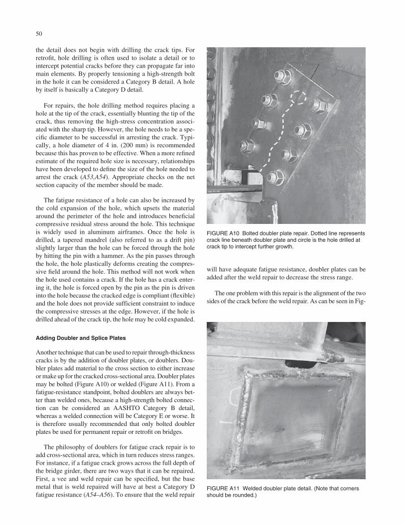
the detail does not begin with drilling the crack tips. Forretrofit, hole drilling is often used to isolate a detail or tointercept potential cracks before they can propagate far intomain elements. By properly tensioning a high-strength boltin the hole it can be considered a Category B detail. A holeby itself is basically a Category D detail.
For repairs, the hole drilling method requires placing ahole at the tip of the crack, essentially blunting the tip of thecrack, thus removing the high-stress concentration associ-ated with the sharp tip. However, the hole needs to be a spe-cific diameter to be successful in arresting the crack. Typi-cally, a hole diameter of 4 in. (200 mm) is recommendedbecause this has proven to be effective. When a more refinedestimate of the required hole size is necessary, relationshipshave been developed to define the size of the hole needed toarrest the crack (A53,A54). Appropriate checks on the netsection capacity of the member should be made.
The fatigue resistance of a hole can also be increased bythe cold expansion of the hole, which upsets the materialaround the perimeter of the hole and introduces beneficialcompressive residual stress around the hole. This techniqueis widely used in aluminum airframes. Once the hole isdrilled, a tapered mandrel (also referred to as a drift pin)slightly larger than the hole can be forced through the holeby hitting the pin with a hammer. As the pin passes throughthe hole, the hole plastically deforms creating the compres-sive field around the hole. This method will not work whenthe hole used contains a crack. If the hole has a crack enter-ing it, the hole is forced open by the pin as the pin is driveninto the hole because the cracked edge is compliant (flexible)and the hole does not provide sufficient constraint to inducethe compressive stresses at the edge. However, if the hole isdrilled ahead of the crack tip, the hole may be cold expanded.
Adding Doubler and Splice Plates
Another technique that can be used to repair through-thicknesscracks is by the addition of doubler plates, or doublers. Dou-bler plates add material to the cross section to either increaseor make up for the cracked cross-sectional area. Doubler platesmay be bolted (Figure A10) or welded (Figure A11). From afatigue-resistance standpoint, bolted doublers are always bet-ter than welded ones, because a high-strength bolted connec-tion can be considered an AASHTO Category B detail,whereas a welded connection will be Category E or worse. Itis therefore usually recommended that only bolted doublerplates be used for permanent repair or retrofit on bridges.
The philosophy of doublers for fatigue crack repair is toadd cross-sectional area, which in turn reduces stress ranges.For instance, if a fatigue crack grows across the full depth ofthe bridge girder, there are two ways that it can be repaired.First, a vee and weld repair can be specified, but the basemetal that is weld repaired will have at best a Category Dfatigue resistance (A54–A56). To ensure that the weld repair
50
will have adequate fatigue resistance, doubler plates can beadded after the weld repair to decrease the stress range.
The one problem with this repair is the alignment of the twosides of the crack before the weld repair. As can be seen in Fig-
FIGURE A10 Bolted doubler plate repair. Dotted line representscrack line beneath doubler plate and circle is the hole drilled atcrack tip to intercept further growth.
FIGURE A11 Welded doubler plate detail. (Note that cornersshould be rounded.)
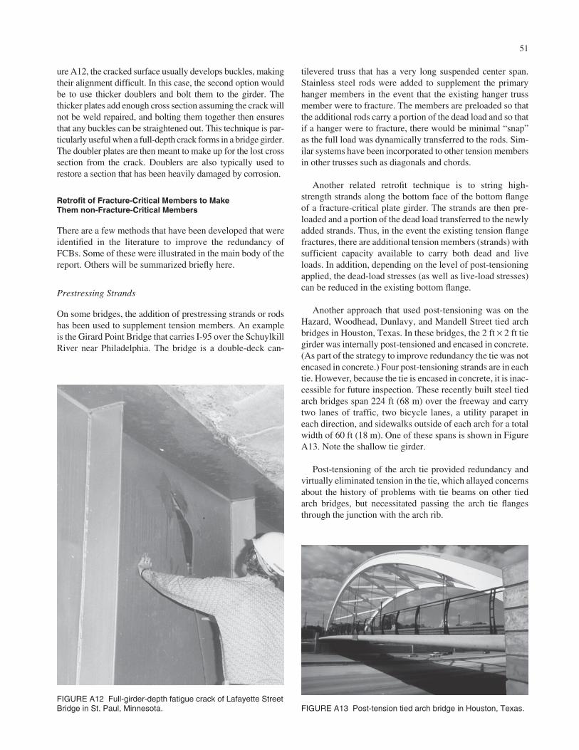
51
ure A12, the cracked surface usually develops buckles, makingtheir alignment difficult. In this case, the second option wouldbe to use thicker doublers and bolt them to the girder. Thethicker plates add enough cross section assuming the crack willnot be weld repaired, and bolting them together then ensuresthat any buckles can be straightened out. This technique is par-ticularly useful when a full-depth crack forms in a bridge girder.The doubler plates are then meant to make up for the lost crosssection from the crack. Doublers are also typically used torestore a section that has been heavily damaged by corrosion.
Retrofit of Fracture-Critical Members to MakeThem non-Fracture-Critical Members
There are a few methods that have been developed that wereidentified in the literature to improve the redundancy ofFCBs. Some of these were illustrated in the main body of thereport. Others will be summarized briefly here.
Prestressing Strands
On some bridges, the addition of prestressing strands or rodshas been used to supplement tension members. An exampleis the Girard Point Bridge that carries I-95 over the SchuylkillRiver near Philadelphia. The bridge is a double-deck can-
tilevered truss that has a very long suspended center span.Stainless steel rods were added to supplement the primaryhanger members in the event that the existing hanger trussmember were to fracture. The members are preloaded so thatthe additional rods carry a portion of the dead load and so thatif a hanger were to fracture, there would be minimal “snap”as the full load was dynamically transferred to the rods. Sim-ilar systems have been incorporated to other tension membersin other trusses such as diagonals and chords.
Another related retrofit technique is to string high-strength strands along the bottom face of the bottom flangeof a fracture-critical plate girder. The strands are then pre-loaded and a portion of the dead load transferred to the newlyadded strands. Thus, in the event the existing tension flangefractures, there are additional tension members (strands) withsufficient capacity available to carry both dead and liveloads. In addition, depending on the level of post-tensioningapplied, the dead-load stresses (as well as live-load stresses)can be reduced in the existing bottom flange.
Another approach that used post-tensioning was on theHazard, Woodhead, Dunlavy, and Mandell Street tied archbridges in Houston, Texas. In these bridges, the 2 ft × 2 ft tiegirder was internally post-tensioned and encased in concrete.(As part of the strategy to improve redundancy the tie was notencased in concrete.) Four post-tensioning strands are in eachtie. However, because the tie is encased in concrete, it is inac-cessible for future inspection. These recently built steel tiedarch bridges span 224 ft (68 m) over the freeway and carrytwo lanes of traffic, two bicycle lanes, a utility parapet ineach direction, and sidewalks outside of each arch for a totalwidth of 60 ft (18 m). One of these spans is shown in FigureA13. Note the shallow tie girder.
Post-tensioning of the arch tie provided redundancy andvirtually eliminated tension in the tie, which allayed concernsabout the history of problems with tie beams on other tiedarch bridges, but necessitated passing the arch tie flangesthrough the junction with the arch rib.
FIGURE A12 Full-girder-depth fatigue crack of Lafayette StreetBridge in St. Paul, Minnesota. FIGURE A13 Post-tension tied arch bridge in Houston, Texas.

Bolted Redundancy Plates
Another technique that has been used on some bridges isthe addition of bolted redundancy plates. This retrofit con-sists of bolting plates or angles to existing tension mem-bers. The primary function is to provide an additional com-ponent(s) so that if the tension flange of an existingmember were to fail at some location along the length, theadded component would assume the full dead and liveloads of the tension flange. For example, the two-girderapproach spans on the Poplar Street Bridge in East St. Louis,Missouri, have been retrofit by bolting thick HPS platesthat would take the place of the tension flange along theweb just above the tension flange, as shown in Figure 15 inchapter two of this report (page 17).
Because the added components are bolted to the existingmember, there is no direct path for the fracture to travel intothe added component. Hence, the member becomes inter-nally redundant as with a riveted built-up member. For exam-ple, in a riveted tension flange comprised of several plates ithas been observed that the cover plate can fully fracture,although the other elements of the member remain and themember continues to take the entire load. When a retrofitplate is added to a bridge with no live load, it also reduces thelive-load stress range in the existing member.
The technique has also been used in new construction ona large truss bridge that carries SR-33 over the Lehigh Rivernear Easton, Pennsylvania. On this new bridge, redundancyplates were bolted alongside of selected tension chords thatwere identified to be critical, as shown in Figure 13 in chap-ter two of the report (page 16). The plates were fully splicedat the panel points and nominally connected to the memberalong the length. An advantage of redundancy plates used inthe design is that the components share both dead and liveloads throughout the life of the bridge.
Although these techniques add internal member redun-dancy, they do not add overall structural load path redun-dancy. In other words, in the unlikely event that the entirelower chord failed only one lower chord remains.
Use of Composite Construction
The SR-33 Bridge near Easton, Pennsylvania, incorporatedan additional measure to increase redundancy. The top chordis fully composite with the concrete deck (see Figure A14).Traditionally, in truss bridges, only the floorbeams andstringers are made composite with the deck. The deck is cast-in-place reinforced concrete supported by steel stringers andtransverse floorbeams. It is the only composite truss in thestate of Pennsylvania and possibly the United States. Thestructure is a four-span continuous haunched steel deck trussthat is composite with the reinforced concrete deck. Themain river span is 181 m and the depth of the trusses variesfrom 11 m to 22 m.
52
Controlled load testing and long-term monitoring of thebridge confirms that there is excellent load distributionbetween trusses and that stresses in the upper chord in thenegative moment regions are very small owing to the com-posite action (A56). Hence, it is believed that the choice tomake the deck composite with the upper chord added sub-stantial redundancy.
Installation of Additional Girders
This retrofit technique is only applied when a structure is tobe widened. In cases where the existing structure is function-ally obsolete and additional or wider lanes are required, anadditional exterior girder is sometimes added. If the newgirder is adequately attached to the existing girders, full loadsharing can be realized. Thus, a two-girder bridge can becomea four-girder bridge and be removed from the list of FCBs inan owner’s inventory. It is emphasized that the new girdermust be sufficiently attached to the existing girder and deck.
This technique was employed on the Pennsylvania Turn-pike near the Valley Forge Interchange northwest of Philadel-phia. In this example, a two-girder bridge was widened byadding parallel girders adjacent to the existing riveted girders.In effect, a two-girder cross section was converted into a four-girder cross section. Although the girder spacings are unequaland the distance between the two original girders may still beconsiderable, the structure as a system should not be consid-ered fracture critical as long as the connections between thegirders and to the concrete deck are adequate.
The additional girders can also be used to retrofit crossgirders. For example, two girders were used to provideredundancy to existing steel cross girders carrying multi-girder composite spans, as shown in Figure A15. The bridgecarries I-95 just north of Philadelphia. The retrofit required
Stringer noteshear studs
Shear studson top chord
FIGURE A14 Shear studs being installed on top chords,floorbeams, and stringers on the SR-33 bridge near Easton,Pennsylvania.
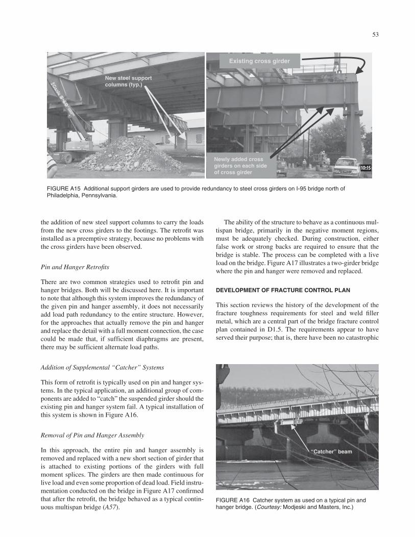
53
the addition of new steel support columns to carry the loadsfrom the new cross girders to the footings. The retrofit wasinstalled as a preemptive strategy, because no problems withthe cross girders have been observed.
Pin and Hanger Retrofits
There are two common strategies used to retrofit pin andhanger bridges. Both will be discussed here. It is importantto note that although this system improves the redundancy ofthe given pin and hanger assembly, it does not necessarilyadd load path redundancy to the entire structure. However,for the approaches that actually remove the pin and hangerand replace the detail with a full moment connection, the casecould be made that, if sufficient diaphragms are present,there may be sufficient alternate load paths.
Addition of Supplemental “Catcher” Systems
This form of retrofit is typically used on pin and hanger sys-tems. In the typical application, an additional group of com-ponents are added to “catch” the suspended girder should theexisting pin and hanger system fail. A typical installation ofthis system is shown in Figure A16.
Removal of Pin and Hanger Assembly
In this approach, the entire pin and hanger assembly isremoved and replaced with a new short section of girder thatis attached to existing portions of the girders with fullmoment splices. The girders are then made continuous forlive load and even some proportion of dead load. Field instru-mentation conducted on the bridge in Figure A17 confirmedthat after the retrofit, the bridge behaved as a typical contin-uous multispan bridge (A57).
The ability of the structure to behave as a continuous mul-tispan bridge, primarily in the negative moment regions,must be adequately checked. During construction, eitherfalse work or strong backs are required to ensure that thebridge is stable. The process can be completed with a liveload on the bridge. Figure A17 illustrates a two-girder bridgewhere the pin and hanger were removed and replaced.
DEVELOPMENT OF FRACTURE CONTROL PLAN
This section reviews the history of the development of thefracture toughness requirements for steel and weld fillermetal, which are a central part of the bridge fracture controlplan contained in D1.5. The requirements appear to haveserved their purpose; that is, there have been no catastrophic
New steel supportcolumns (typ.)
Existing cross girder
Newly added crossgirders on each sideof cross girder
FIGURE A15 Additional support girders are used to provide redundancy to steel cross girders on I-95 bridge north ofPhiladelphia, Pennsylvania.
“Catcher” beam
FIGURE A16 Catcher system as used on a typical pin andhanger bridge. (Courtesy: Modjeski and Masters, Inc.)
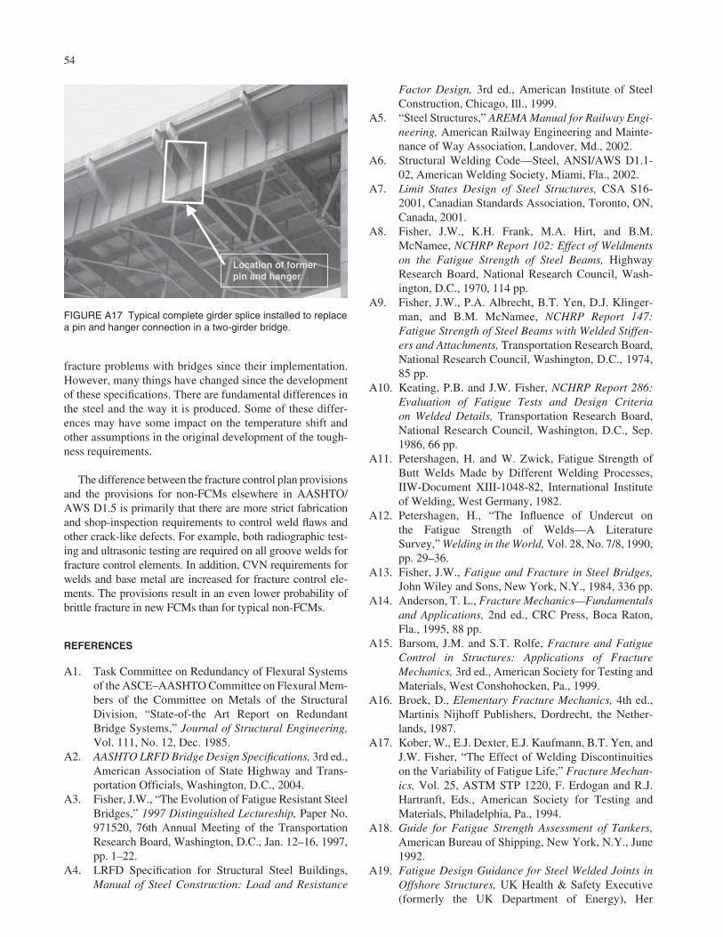
fracture problems with bridges since their implementation.However, many things have changed since the developmentof these specifications. There are fundamental differences inthe steel and the way it is produced. Some of these differ-ences may have some impact on the temperature shift andother assumptions in the original development of the tough-ness requirements.
The difference between the fracture control plan provisionsand the provisions for non-FCMs elsewhere in AASHTO/AWS D1.5 is primarily that there are more strict fabricationand shop-inspection requirements to control weld flaws andother crack-like defects. For example, both radiographic test-ing and ultrasonic testing are required on all groove welds forfracture control elements. In addition, CVN requirements forwelds and base metal are increased for fracture control ele-ments. The provisions result in an even lower probability ofbrittle fracture in new FCMs than for typical non-FCMs.
REFERENCES
A1. Task Committee on Redundancy of Flexural Systemsof the ASCE–AASHTO Committee on Flexural Mem-bers of the Committee on Metals of the StructuralDivision, “State-of-the Art Report on RedundantBridge Systems,” Journal of Structural Engineering,Vol. 111, No. 12, Dec. 1985.
A2. AASHTO LRFD Bridge Design Specifications, 3rd ed.,American Association of State Highway and Trans-portation Officials, Washington, D.C., 2004.
A3. Fisher, J.W., “The Evolution of Fatigue Resistant SteelBridges,” 1997 Distinguished Lectureship, Paper No.971520, 76th Annual Meeting of the TransportationResearch Board, Washington, D.C., Jan. 12–16, 1997,pp. 1–22.
A4. LRFD Specification for Structural Steel Buildings,Manual of Steel Construction: Load and Resistance
54
Factor Design, 3rd ed., American Institute of SteelConstruction, Chicago, Ill., 1999.
A5. “Steel Structures,” AREMA Manual for Railway Engi-neering, American Railway Engineering and Mainte-nance of Way Association, Landover, Md., 2002.
A6. Structural Welding Code—Steel, ANSI/AWS D1.1-02, American Welding Society, Miami, Fla., 2002.
A7. Limit States Design of Steel Structures, CSA S16-2001, Canadian Standards Association, Toronto, ON,Canada, 2001.
A8. Fisher, J.W., K.H. Frank, M.A. Hirt, and B.M.McNamee, NCHRP Report 102: Effect of Weldmentson the Fatigue Strength of Steel Beams, HighwayResearch Board, National Research Council, Wash-ington, D.C., 1970, 114 pp.
A9. Fisher, J.W., P.A. Albrecht, B.T. Yen, D.J. Klinger-man, and B.M. McNamee, NCHRP Report 147:Fatigue Strength of Steel Beams with Welded Stiffen-ers and Attachments, Transportation Research Board,National Research Council, Washington, D.C., 1974,85 pp.
A10. Keating, P.B. and J.W. Fisher, NCHRP Report 286:Evaluation of Fatigue Tests and Design Criteria on Welded Details, Transportation Research Board,National Research Council, Washington, D.C., Sep.1986, 66 pp.
A11. Petershagen, H. and W. Zwick, Fatigue Strength ofButt Welds Made by Different Welding Processes,IIW-Document XIII-1048-82, International Instituteof Welding, West Germany, 1982.
A12. Petershagen, H., “The Influence of Undercut on the Fatigue Strength of Welds—A Literature Survey,” Welding in the World, Vol. 28, No. 7/8, 1990,pp. 29–36.
A13. Fisher, J.W., Fatigue and Fracture in Steel Bridges,John Wiley and Sons, New York, N.Y., 1984, 336 pp.
A14. Anderson, T. L., Fracture Mechanics—Fundamentalsand Applications, 2nd ed., CRC Press, Boca Raton,Fla., 1995, 88 pp.
A15. Barsom, J.M. and S.T. Rolfe, Fracture and FatigueControl in Structures: Applications of FractureMechanics, 3rd ed., American Society for Testing andMaterials, West Conshohocken, Pa., 1999.
A16. Broek, D., Elementary Fracture Mechanics, 4th ed.,Martinis Nijhoff Publishers, Dordrecht, the Nether-lands, 1987.
A17. Kober, W., E.J. Dexter, E.J. Kaufmann, B.T. Yen, andJ.W. Fisher, “The Effect of Welding Discontinuitieson the Variability of Fatigue Life,” Fracture Mechan-ics, Vol. 25, ASTM STP 1220, F. Erdogan and R.J.Hartranft, Eds., American Society for Testing andMaterials, Philadelphia, Pa., 1994.
A18. Guide for Fatigue Strength Assessment of Tankers,American Bureau of Shipping, New York, N.Y., June1992.
A19. Fatigue Design Guidance for Steel Welded Joints inOffshore Structures, UK Health & Safety Executive(formerly the UK Department of Energy), Her
Location of formerpin and hanger
FIGURE A17 Typical complete girder splice installed to replacea pin and hanger connection in a two-girder bridge.
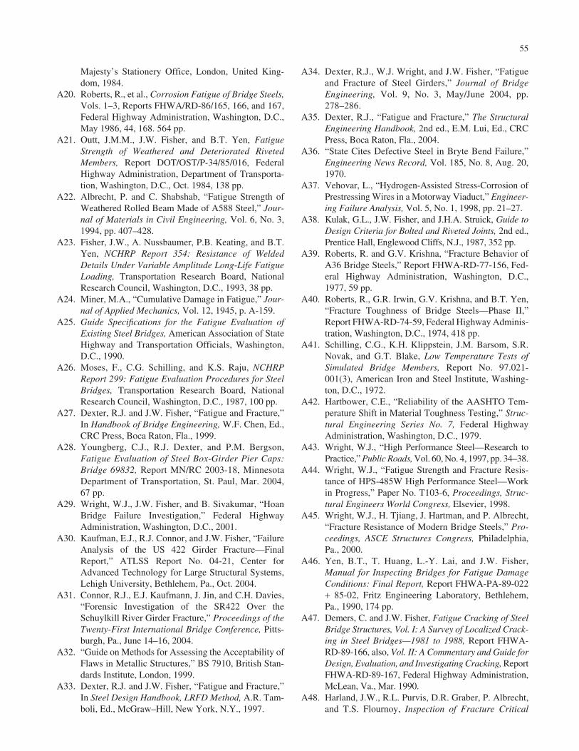
55
Majesty’s Stationery Office, London, United King-dom, 1984.
A20. Roberts, R., et al., Corrosion Fatigue of Bridge Steels,Vols. 1–3, Reports FHWA/RD-86/165, 166, and 167,Federal Highway Administration, Washington, D.C.,May 1986, 44, 168. 564 pp.
A21. Outt, J.M.M., J.W. Fisher, and B.T. Yen, FatigueStrength of Weathered and Deteriorated RivetedMembers, Report DOT/OST/P-34/85/016, FederalHighway Administration, Department of Transporta-tion, Washington, D.C., Oct. 1984, 138 pp.
A22. Albrecht, P. and C. Shabshab, “Fatigue Strength ofWeathered Rolled Beam Made of A588 Steel,” Jour-nal of Materials in Civil Engineering, Vol. 6, No. 3,1994, pp. 407–428.
A23. Fisher, J.W., A. Nussbaumer, P.B. Keating, and B.T.Yen, NCHRP Report 354: Resistance of WeldedDetails Under Variable Amplitude Long-Life FatigueLoading, Transportation Research Board, NationalResearch Council, Washington, D.C., 1993, 38 pp.
A24. Miner, M.A., “Cumulative Damage in Fatigue,” Jour-nal of Applied Mechanics, Vol. 12, 1945, p. A-159.
A25. Guide Specifications for the Fatigue Evaluation ofExisting Steel Bridges, American Association of StateHighway and Transportation Officials, Washington,D.C., 1990.
A26. Moses, F., C.G. Schilling, and K.S. Raju, NCHRPReport 299: Fatigue Evaluation Procedures for SteelBridges, Transportation Research Board, NationalResearch Council, Washington, D.C., 1987, 100 pp.
A27. Dexter, R.J. and J.W. Fisher, “Fatigue and Fracture,”In Handbook of Bridge Engineering, W.F. Chen, Ed.,CRC Press, Boca Raton, Fla., 1999.
A28. Youngberg, C.J., R.J. Dexter, and P.M. Bergson,Fatigue Evaluation of Steel Box-Girder Pier Caps:Bridge 69832, Report MN/RC 2003-18, MinnesotaDepartment of Transportation, St. Paul, Mar. 2004,67 pp.
A29. Wright, W.J., J.W. Fisher, and B. Sivakumar, “HoanBridge Failure Investigation,” Federal HighwayAdministration, Washington, D.C., 2001.
A30. Kaufman, E.J., R.J. Connor, and J.W. Fisher, “FailureAnalysis of the US 422 Girder Fracture—FinalReport,” ATLSS Report No. 04-21, Center forAdvanced Technology for Large Structural Systems,Lehigh University, Bethlehem, Pa., Oct. 2004.
A31. Connor, R.J., E.J. Kaufmann, J. Jin, and C.H. Davies,“Forensic Investigation of the SR422 Over theSchuylkill River Girder Fracture,” Proceedings of theTwenty-First International Bridge Conference, Pitts-burgh, Pa., June 14–16, 2004.
A32. “Guide on Methods for Assessing the Acceptability ofFlaws in Metallic Structures,” BS 7910, British Stan-dards Institute, London, 1999.
A33. Dexter, R.J. and J.W. Fisher, “Fatigue and Fracture,”In Steel Design Handbook, LRFD Method, A.R. Tam-boli, Ed., McGraw–Hill, New York, N.Y., 1997.
A34. Dexter, R.J., W.J. Wright, and J.W. Fisher, “Fatigueand Fracture of Steel Girders,” Journal of BridgeEngineering, Vol. 9, No. 3, May/June 2004, pp.278–286.
A35. Dexter, R.J., “Fatigue and Fracture,” The StructuralEngineering Handbook, 2nd ed., E.M. Lui, Ed., CRCPress, Boca Raton, Fla., 2004.
A36. “State Cites Defective Steel in Bryte Bend Failure,”Engineering News Record, Vol. 185, No. 8, Aug. 20,1970.
A37. Vehovar, L., “Hydrogen-Assisted Stress-Corrosion ofPrestressing Wires in a Motorway Viaduct,” Engineer-ing Failure Analysis, Vol. 5, No. 1, 1998, pp. 21–27.
A38. Kulak, G.L., J.W. Fisher, and J.H.A. Struick, Guide toDesign Criteria for Bolted and Riveted Joints, 2nd ed.,Prentice Hall, Englewood Cliffs, N.J., 1987, 352 pp.
A39. Roberts, R. and G.V. Krishna, “Fracture Behavior ofA36 Bridge Steels,” Report FHWA-RD-77-156, Fed-eral Highway Administration, Washington, D.C.,1977, 59 pp.
A40. Roberts, R., G.R. Irwin, G.V. Krishna, and B.T. Yen,“Fracture Toughness of Bridge Steels—Phase II,”Report FHWA-RD-74-59, Federal Highway Adminis-tration, Washington, D.C., 1974, 418 pp.
A41. Schilling, C.G., K.H. Klippstein, J.M. Barsom, S.R.Novak, and G.T. Blake, Low Temperature Tests ofSimulated Bridge Members, Report No. 97.021-001(3), American Iron and Steel Institute, Washing-ton, D.C., 1972.
A42. Hartbower, C.E., “Reliability of the AASHTO Tem-perature Shift in Material Toughness Testing,” Struc-tural Engineering Series No. 7, Federal HighwayAdministration, Washington, D.C., 1979.
A43. Wright, W.J., “High Performance Steel—Research toPractice,” Public Roads, Vol. 60, No. 4, 1997, pp. 34–38.
A44. Wright, W.J., “Fatigue Strength and Fracture Resis-tance of HPS-485W High Performance Steel—Workin Progress,” Paper No. T103-6, Proceedings, Struc-tural Engineers World Congress, Elsevier, 1998.
A45. Wright, W.J., H. Tjiang, J. Hartman, and P. Albrecht,“Fracture Resistance of Modern Bridge Steels,” Pro-ceedings, ASCE Structures Congress, Philadelphia,Pa., 2000.
A46. Yen, B.T., T. Huang, L.-Y. Lai, and J.W. Fisher,Manual for Inspecting Bridges for Fatigue DamageConditions: Final Report, Report FHWA-PA-89-022+ 85-02, Fritz Engineering Laboratory, Bethlehem,Pa., 1990, 174 pp.
A47. Demers, C. and J.W. Fisher, Fatigue Cracking of SteelBridge Structures, Vol. I: A Survey of Localized Crack-ing in Steel Bridges—1981 to 1988, Report FHWA-RD-89-166, also, Vol. II: A Commentary and Guide forDesign, Evaluation, and Investigating Cracking, ReportFHWA-RD-89-167, Federal Highway Administration,McLean, Va., Mar. 1990.
A48. Harland, J.W., R.L. Purvis, D.R. Graber, P. Albrecht,and T.S. Flournoy, Inspection of Fracture Critical

Bridge Members, supplement to the Bridge Inspec-tor’s Training Manual, final report, Report FHWA-IP-86-26 (PB87-163440), Federal Highway Administra-tion, McLean, Va., Sept. 1986, 232 pp.
A49. Braid, J., R. Bell, and D. Militaru, “Fatigue Life of as-Welded, Repaired, and Hammer-Peened Joints inHigh-Strength Structural Steel,” Welding in theWorld/Le Soudage le Monde, Vol. 39, No. 5, 1998,pp. 248–261.
A50. Harrison, J.D., “Further Techniques for Improving theFatigue Strength of Welded Joints,” British WeldingJournal, Vol. 13, No. 11, 1966.
A51. Tryfyakov, V., P. Mikheev, Y. Kudryavtsev, and D.Reznik, “Ultrasonic Impact Peening Treatments ofWelds and Its Effect on Fatigue Resistance in Air andSeawater,” 25th Annual Offshore Technology Confer-ence, Houston, Tex., May 3–6, 1993.
A52. Roy, S., J. Fisher, and B. Yen, “Fatigue Resistance of Welded Details Enhanced by Ultrasonic ImpactTreatment (UIT),” Proceedings of the Eleventh International Offshore and Polar Engineering Con-ference, Stavenger, Norway, June 17–22, 2001, pp. 309–313.
56
A53. Fisher, J., B.M. Barthelemy, D.R. Mertz, and J.A.Edinger, NCHRP Report 227: Fatigue Behavior ofFull-Scale Welded Bridge Attachments, Transporta-tion Research Board, National Research Council,Washington, D.C., 1980, 47 pp.
A54. Dexter, R., R. Fitzpatrick, and D. St. Peter, “FatigueStrength and Adequacy of Fatigue Crack Repairs,”Report SSC-425, Ship Structure Committee, Wash-ington, D.C., May 2003.
A55. Gregory, E.N., G. Slater, and C.C. Woodley, NCHRPReport 321: Welded Repair of Cracks in Steel BridgeMembers, Transportation Research Board, NationalResearch Council, Washington, D.C., 1989, 52 pp.
A56. Dexter, R.J. and B.A. Kelly, “Research on Repair andImprovement Methods,” International Conference onPerformance of Dynamically Loaded Welded Struc-tures, Proceedings of the IIW 50th Annual AssemblyConference, San Francisco, Calif., July 13–19, 1997,pp. 273–285.
A57. Frank, K.H. and C.F. Galambos, “Application ofFracture Mechanics to Analysis of Bridge Failure,”Proceedings, Specialty Conference on Safety and Re-liability of Metal Structures, 1972.

57
QUESTIONNAIRE
NCHRP SYNTHESIS TOPIC 35-08
INSPECTION AND MANAGEMENT OF BRIDGES WITH FRACTURE CRITICAL MEMBERS
Please complete and return this questionnaire by March 19, 2004
Name:Title:Agency:Address:City:State:Zip:Phone:Fax:E-mail:
Please return the completed questionnaire to:
Robert J. ConnorLehigh University117 ATLSS DriveBethlehem, PA 18015Phone: (610) 758-6103 Fax: (610) 758-5553Email: [email protected]
We would greatly appreciate discussing any matters related to this survey with you on the telephone. If you have any ques-tions, comments, or can provide any additional information that is not identified in the questionnaire, please do not hesitate tocall myself at 610-758-6103 or Robert J. Dexter at 612-624-0063.
Background
During the past three decades, special emphasis has been placed on the evaluation, inspection, and rehabilitation of bridgescontaining fracture-critical members (FCMs). FCMs are steel members in tension or with tension elements whose failurewould probably cause a portion of or the entire bridge to catastrophically collapse. Bridges containing FCMs are commonlyreferred to as fracture-critical bridges (FCBs).
This survey is being conducted as part of NCHRP Synthesis Topic 35-08: Inspection and Management of Bridges withFracture Critical Members. One of the objectives of this survey is to gather information on fracture-critical structures and howbridge owners define, identify, inspect, and manage FCBs.
Notes for Completing this Survey
A copy of this survey should be given to all departments within your agency that have significant experience with FCBs(e.g., designers, inspectors, district bridge engineers). Multiple responses from a single agency are welcomed and encouraged.
APPENDIX B
Survey Questionnaire

It would be advantageous to provide a copy to the individuals within the agency with the most experience and familiarity withthe history of the bridge inspection and maintenance program of the agency.
In responding to all of the questions below, if you do not have exact information or if it would be very difficult to obtain,please feel free to estimate the approximate answer and indicate that it is an estimate. It is better to have an estimate than noinformation at all. Also, please provide sketches, drawings, photographs, inspection reports and any other useful informationif available. If you have such material in digital format, please send it via e-mail if possible. If this additional information isnot digital in format, you can send this to us by regular mail. If you request, we will return it to you right away.
QUESTIONNAIRE
PART I—GENERAL1. How does your agency define a fracture-critical bridge?
Nearly all agencies responded that they either use the AASHTO or NBIS definitions.
2. Are different criteria used for different structural systems (e.g., are trusses identified using different criteria than box girders)?
33 No7 Yes
If yes, please describe the criteria:
Results indicated the criteria are developed for specific projects on case-by-case basis. Some rely on a rank-ing system to prioritize inspection procedures based on age, average daily traffic, type of material, and type offatigue details on the bridge.
3. How would you categorize the following bridges (place an ‘X’ in the box to select the type of bridge)?
CHAPTER 10. DescriptionFracture Critical
Yes No
Two girder bridges 38 0
Three girder bridges 9 28
Three girder bridges with girder spacing > ______ ft 10 21
Multi-girder bridges with girder spacing >_______ft 3 32
Truss bridges 34 3
Two girder bridges fabricated using HPS 70W 31 1
Truss bridges fabricated using HPS 70W steel 28 2
Single steel “tub” girder bridges 32 5
Twin steel “tub” girder bridges 22 12
Multi-steel “tub” girder bridges 0 34
Other (post-tensioned, timber, steel cross girders, etc.) 13 3
Are these answers your opinion or your agency’s written policy?
Engineering judgment in conjunction with established policies; e.g., NBIS and AASHTO.
4. Does your agency identify suspension bridges as fracture critical?
8 No25 Yes
58

59
If yes, what elements are considered fracture critical?______________________________________________________________________________________________________________________________________________
5. Does your agency currently have any fracture-critical bridges in its inventory?
1 No39 Yes
If you answered “yes” to question 5, please continue and complete the survey. If you answered “no,” please return thesurvey to the address listed above. We thank you for your time. (ID = insufficient data.)
PART II—INSPECTION AND CLASSIFICATION
1. How many steel bridges are in your inventory? 85,723a. How many are fracture critical? 11.8%
How many fracture-critical bridges were built before 1975? 76%How many fracture-critical bridges were built before 1985? 70% (ID)
b. How many are non-fracture critical? 80%How many non-fracture-critical bridges were built before 1975? 67%How many non-fracture-critical bridges were built before 1985? 81%
2. Please provide a breakdown of the approximate number of each type of structure identified as fracture critical in yourinventory. Some common types of bridges often identified as fracture critical are listed below:
16.4% Welded two-girder system (with bolted or welded field splices)1.0% Welded three-girder system (with bolted or welded field splices)<1% Other welded girder systems considered fracture critical
8.6% Riveted two-girder system<1% Riveted three-girder system<1% Other riveted girder systems considered fracture critical
30.9% Riveted truss bridges with two truss lines3.8% Welded truss bridges with two truss lines (with bolted or welded field splices)1.6% Welded and bolted truss bridges with two truss lines
28% Bridges with steel pier caps1.5% Bridges with pin and hanger systems6.1% Bridges with steel cross girders
<1% Bridges with single steel tub girders<1% Bridges with twin steel tub girders1.1% Bridges with multi-steel tub girders
7.5% Other steel bridges considered fracture critical
Please describe: Steel cross girders, cable supported, tied arch.
3.1% Other non-steel bridges (e.g., wood or post-tensioned concrete) considered fracture critical. Please describe:______________________________________________________________________________________________________________________________________________________________________________
3. Does your agency require any special inspection procedures for fracture-critical bridges?
11 No29 Yes

If yes, please describe below:
Examples given: hands-on, arms length at defined intervals.
4. Does your agency require any special training or qualifications for individuals inspecting fracture-critical bridges?
17 No23 Yes
If yes, please describe below:
Examples given: NHI, in-house training, FCB inspection team lead must have experience and in most casesbe a PE.
5. What is the maximum interval (in years) between inspections of typical non-fracture-critical bridges permitted by youragency?
Two years typically, 5 years maximum for in-depth.
6. What is the maximum interval (in years) between inspections of typical fracture-critical bridges permitted by your agency?
Two years typically, 5 years maximum for in-depth.
7. Are there any special methods or nondestructive testing techniques required by your agency to inspect fracture-critical bridges?
25 Yes
If yes, please briefly describe:
Dye penetrant, UT, magnetic particle testing.
15 No
The next two questions make a distinction between cursory inspection and detailed “hands-on” inspection. Your agencymay not make such a distinction, so the answers would be the same.
8. What is the maximum interval (in years) between detailed “hands-on” inspections of typical non-fracture-critical bridgepermitted by your agency?
5
9. What is the maximum interval (in years) between detailed “hands-on” inspections of typical fracture-critical bridgepermitted by your agency?
5
10. If fracture-critical bridges are inspected at a greater frequency than non-fracture-critical bridges, is the entire bridgeinspected more frequently or just the fracture-critical members?
Most agencies answered no to this question and that interval is based on a case-by-case basis. Some agen-cies indicated that they only inspected the FCM, while others indicated the entire bridge is inspected sincecrews and equipment are on site.
11. Is there any significant increase in the costs associated with the inspection of fracture-critical bridges?
13 No26 Yes
60

61
If you answered “yes” to question 11, what are the reasons for the increased costs (e.g., increased frequency of inspec-tion, increased cost per inspection)?
Traffic control, additional time on site to perform in-depth inspection, added equipment costs such as snooper,testing equipment, special FCB inspection team, etc.
Can you attempt to estimate at the absolute or percentage increase in cost? (e.g., 10%, 15%, . . . etc.)
Increase in cost due to frequency of inspection __________Increase in cost per inspection __________Other factors (please describe): _________________________________________________________________________________________________________________________________________________________________
12. Is there any special or advanced analysis performed to identify which specific members are fracture critical or if the struc-ture is actually fracture critical (e.g., 3-D structural analysis, etc.)?
32 No8 Yes
If yes, please describe below:
Some owners indicated that 3-D modeling has been conducted on a case-by-case basis, but none had adefined policy.
13. Has the inspection of a fracture-critical bridge(s) ever identified a condition that has clearly prevented a fracture and thesubsequent collapse of the structure? (The objective of this question is to identify specific cases or examples whereby theadditional inspection efforts dedicated to FCBs prevented a failure that would have occurred had the inspection not beencarried out. For example, the discovery of typical out-of-plane distortion cracks, which usually take years to become crit-ical, would not warrant a response of “yes” for this question. Furthermore, inspections which found fractured memberswould also not warrant a response of “yes” for this question since the inspection did not prevent the fracture and the bridgedid not fail.)
27 No8 Yes
14. If you answered “yes” to question 13, please describe the problem(s) in detail. Bridge name and/or inventory number,location, year built:
Questions 13 and 14 did not provide information intended. Question 13 was not worded clearly enough to deter-mine if inspection program found immediate problems. Only a few owners replied to both questions. Overall, mostwho replied felt inspection permitted them to find and correct a problem before failure occurred.
15. If a bridge normally identified as fracture critical had all fracture-critical members fabricated from HPS 70W steel, wouldthere be any changes to the inspection methods or interval that you would recommend?
Nearly all owners answered “no” to this question. However, the reason given for a response of “no” was almostalways because FHWA/NBIS does not allow a change in inspection requirements if HPS 70W is used.
16. If a bridge normally identified as fracture critical was fabricated so that the worst fatigue category used was Category Cwould there be any changes to the inspection methods or interval that you would recommend? (Most multi-beam bridgesbuilt in the last twenty years do not have details worse than Category C.)
Nearly all owners answered no to this question.
17. It is commonly observed that by using simplified structural analysis methods the calculations for many bridges indicateno remaining fatigue life or even “negative” fatigue life. These calculations imply that fatigue cracking should be observedpresently or in the near future on these bridges. However, such bridges typically show no signs of fatigue-related prob-

lems. (Please note this does not include cracking from secondary stresses, such as web gap cracking, as this type of crack-ing is not explicitly considered in fatigue rating calculations.)
What is your agency’s policy regarding cases when this inconsistency occurs?
One state relied on a fracture mechanics approach to evaluate potential for fracture. Interestingly, many statesdo not check fatigue life on FCBs. Others, if they check fatigue, will retrofit the bridge or post the bridge. Over-all, none of the agencies that replied indicated a defined procedure to address this issue.
18. Are more rigorous methods ever used such as:
a. Weigh-in-motion studies to better characterize loading
Yes 4
If yes, how many bridges per year _____.
No 36
b. Advanced analysis, such as grid or 3-D frame analysis
Yes 13
If yes, how many bridges per year _____.
No 27
c. Field instrumentation and/or controlled load testing or monitoring
Yes 18
If yes, how many bridges per year _____.
No 22
Please describe other methods and provide procedures as necessary.________________________________________________________________________________________________________________________________________________________________________________________________
19. What criteria are used to identify bridges that will be evaluated using the more rigorous methods for a fatigue evaluation?Owners indicated that these additional efforts are undertaken on a case-by-case basis.
Influencing factors are structure size, age, average daily traffic, type of fatigue details on the bridge, overallcondition (including fatigue problems) of the bridge.
20. In performing a fatigue evaluation, does your agency use a specific procedure for fracture-critical bridges?
9 Yes30 No
21. If you answered “yes” to question 19, what is your level of confidence in these procedures?
____ Low____ Medium____ High
Very few agencies answered this question. Those who replied indicated low-to-medium confidence.
62

63
PART III—FAILURES
The failures of interest in this section are only related to fractures. Cracking associated with fatigue that did not result in frac-ture should not be included in this group. However, fractures that have occurred as a result of a fatigue crack should beincluded. For all failures cited, please provide a description of the bridge, failure, inventory number of the bridge, and anyother information you can provide. (ID = insufficient data.)
1. Has your agency ever experienced the failure of any non-fracture-critical bridges the cause of which could be attributedto any reason, such as fracture of a member, scour, vehicle impact, . . . etc?
8 No31 Yes
2. If you answered “yes” to question 1, were there any fatalities? (Please provide information for each failure.)
20 No13 Yes
If yes, how many? ID
3. Has your agency ever experienced the failure of any fracture-critical bridges the cause of which was attributed to rea-sons other than fatigue or fracture of a member, such as, scour, impact, . . . etc?
24 No16 Yes
If yes, how many were prior to the implementation of the fracture-critical bridge inspection program (1975 for most agencies)? ________ID_______
Bridge name and/or inventory number, location: _________________________________________________________________________________________________________________________________________________________
If yes, how many were after the implementation of the fracture-critical bridge inspection program? ________ID_______
Bridge name and/or inventory number, location: _________________________________________________________________________________________________________________________________________________________
4. If you answered “yes” to question 3, were there any fatalities? (Please provide information for each failure.)
11 No2 Yes
If yes, how many? ID
5. Has your agency ever experienced the failure of any fracture-critical bridges the cause of which was clearly attributed tofatigue or fracture of a member?
35 No4 Yes
If yes, how many? ID
If yes, how many were prior to the implementation of the fracture-critical bridge inspection program (1975 for most agencies)? ________ID_______
Bridge name and/or inventory number, location: _________________________________________________________________________________________________________________________________________________________

If yes, how many were after the implementation of the fracture-critical bridge inspection program? ________ID_______
Bridge name and/or inventory number, location: _________________________________________________________________________________________________________________________________________________________
If you answered yes to question 5 were there any fatalities?
ID NoID Yes
If yes, how many? ______________ (Please provide information for each failure.)
6. Has your agency ever experienced a brittle fracture in a member of a fracture-critical bridge in which the bridge did notcollapse catastrophically but remained standing? (For example, a girder may have fractured with damage only resultingin significant deflections or local buckling of other members.)
29 No10 Yes
If yes, how many? ________ID_______
If yes, how many were prior to the implementation of the fracture-critical bridge inspection program (1975 for most agencies)? ________ID_______
Bridge name and/or inventory number, location: _________________________________________________________________________________________________________________________________________________________
If yes, how many were after the implementation of the fracture-critical bridge inspection program? ID
Bridge name and/or inventory number, location: _________________________________________________________________________________________________________________________________________________________
7. Have existing small fatigue cracks ever been observed to propagate significantly (greater than 6 inches) between regu-larly scheduled inspections?
29 No11 Yes
If yes, how many were prior to the implementation of the fracture-critical bridge inspection program (1975 for most agencies)? ________ID_______
Bridge name and/or inventory number, location: _________________________________________________________________________________________________________________________________________________________
If yes, how many were after the implementation of the fracture-critical bridge inspection program? ________ID_______
Bridge name and/or inventory number, location: _________________________________________________________________________________________________________________________________________________________
8. Have fatigue cracks ever resulted in fracture of a fracture-critical member?
34 No4 Yes
If yes, how many were prior to the implementation of the fracture-critical bridge inspection program (1975 for most agencies)? ________ID_______
Bridge name and/or inventory number, location: _________________________________________________________________________________________________________________________________________________________
64

65
If yes, how many were after the implementation of the fracture-critical bridge inspection program? ID
Bridge name and/or inventory number, location: _________________________________________________________________________________________________________________________________________________________
9. If you answered “yes” to question 8, were tests conducted to determine the material properties of the steel?
1 No5 Yes
10. If you answered “yes” to question 8, has it been confirmed through a detailed investigation that the fractures were initi-ated by the fatigue crack?
1 No4 Yes
11. What was determined to be the specific cause of the fracture?
There were very few responses to this question. Where additional information was given, fatigue, impact fromships, or constraint-induced fracture originating at intersecting weld (Hoan-like failure) were identified as thecauses.
12. How long (in inches) was the fatigue crack at the time of fracture? (Please attach sketches, photographs, etc., as required.)
ID
13. Would you be willing to speak with us over the telephone to discuss these failure(s) further?
6 No15 Yes
PART IV—RETROFIT PROCEDURES
1. Has your state or agency developed any policies for retrofit of bridges identified as fracture critical to improve redundancy?
30 No7 Yes
2. Please provide copies of these policies. (Please attach documents as required.)
ID
3. Have the retrofits been implemented or been scheduled to be implemented in the field on any bridges to date?
13 No15 Yes
4. Can your agency identify any research needs related to fracture-critical steel bridges?
6 No.6 Yes—if yes, please describe below. Some examples are provided below that can simply be checked.8 Develop guidelines related to advanced structural analysis procedures to better predict service load behavior in
fracture-critical bridges.9 Develop advanced fatigue-life calculation procedures taking into account lack of visible cracks for fracture-
critical bridges.10 Field monitoring for fracture-critical bridges.3 Crack arrest capabilities of bridge steel.

7 Establish evaluation procedures for advanced large deformation and member death.10 Develop advanced analyses techniques and procedures to investigate alternate load paths, redundancy, and bridge
collapse.1 Retrofit procedures to add redundancy.
Others you may wish to suggest:
ID—See responses to question 5 of this section.
5. Can your agency suggest any changes in the current practice of identifying, inspecting, or retrofitting fracture-critical steelbridges?
_____ No_____ Yes
If yes, please describe below.
• Develop methods to establish inspection intervals and criteria based on ADT/ADTT, age, detail types, exist-ing condition, etc.
• Develop fracture-critical inspection procedures for high-mast lighting towers, overhead sign bridges. Thesestructures should be considered as fracture critical according to one respondent. The individual indicatedthat these structures are more problematic than their fracture critical bridges.
Survey Completed—Thank You for Your Time
66

67
U.S. State Departments of Transportation
AlaskaArizonaArkansasCaliforniaColoradoDelawareGeorgiaHawaiiIllinoisIndianaIowaKansasKentuckyMarylandMichiganMinnesotaMississippi
Canadian Provinces
AlbertaQuebecNew Brunswick
APPENDIX C
List of Survey Respondents
MissouriNebraskaNevadaNew JerseyNew MexicoNew YorkNorth CarolinaOklahomaOregonPennsylvaniaTennesseeTexasVirginiaWashingtonWest VirginiaWisconsin
68
1. Idriss, R.L., K.R. White, and D.V. Jauregui, “After-Fracture Response of a Two-Girder Steel Bridge,” Natural HazardsMitigation, Presented at the Structures Congress ‘93, Irvine, Calif., Apr. 19–21, 1993.
Idriss et al. (1) developed a computer model to study the after-fracture response of I-40 two-girder bridges. Field test data (2)were used to validate or modify the analytical model. The main focus of the analysis was to investigate the way in which theload distributes, the maximum load the bridge could withstand, and the potential for the bridge to collapse after a full-depthcrack was introduced in one of the bridge girders. The analysis showed that the structure remained stable after the crack wasintroduced. The stability of the structure was attributed to a large surge in the tension force of the lateral bracing, which helpedin stiffening and stabilizing the structure.
2. Idriss, R.L., K.R. White, C.B. Woodward, and D.V. Jauregui, “After-Fracture Redundancy of Two-Girder Bridge: Test-ing I-40 Bridges Over Rio Grande,” Conference Proceedings 7, Fourth International Bridge Engineering Conference, SanFrancisco, Calif., Aug. 28–30, 1995, pp. 316–326.
Idriss et al. (2) conducted field testing on I-40 bridges over the Rio Grande in Albuquerque, New Mexico. The bridges werebuilt in 1963 and were classified by AASHTO as nonredundant fracture critical. Similar to the intention of the analytical model(1), the main focus of the authors was to study the redistribution of loads, the load capacity the bridge can withstand, and thepotential for collapse. The bridges were loaded in the positive moment region with a truck that was 95% of New Mexico legalload, and roughly equivalent to HS-18.35.
The truck load was placed on the bridge four different times as four different levels of damage were introduced in one ofthe girders in the bridge. The fourth level of damage was such that a 6-ft crack was introduced in one of the 10-ft girders. Thecrack stretched to include the bottom flange, which was totally severed (only 4 ft of the web and the top flange were left tocarry the bridge).
Idriss et al. reported that under dead and live loads, and when the truck was located above the crack, the flange deflected 13/16 in. There was no sign of yielding, with no significant change in strains experienced by the gauged members until thebottom flange was completely severed. In other words, load redistribution did not occur until the bottom flange was completelysevered. Another important finding was that most of the load was redistributed through the damaged girder and stringer decksystem to the interior supports. In general, the load was redistributed through the damaged girder, the diagonals, the stringers,the deck, and the floorbeams.
3. Idriss, R.L. and K.R. White, “Secondary Load Paths in Bridge Systems,” Transportation Research Record 1290, Trans-portation Research Board, National Research Council, Washington, D.C., 1991, pp. 194–201.
Idriss and White (3) studied the secondary load path in a four-girder bridge using finite-element analysis. The focus of thestudy was to investigate the distribution of the loads and the secondary load paths along which a load is transmitted when dam-age occurs in the given set of proportionate structures. Three finite-element analyses were conducted and the results were com-pared with experimental results from an AASHTO road test conducted in the early 1960s on four bridges.
The load-deflection response showed good agreement between the finite-element model and the experimental results upto the load causing the first plastic hinge. Beyond that point, the actual structure showed much greater deflection than themodel. The analysis was also conducted with three types of defects modeled at midspan in one of the two exterior girders.The first defect was a 50% loss in the flange section for a distance of 5 ft 6 in. at about the centerline of the girder, whereasthe second defect was a 100% loss. The third defect included a crack at midspan in the bottom flange extending upwardthrough the full depth of the web plate. The first sign of an excessive yielding with a plastic hinge was observed in the defec-tive girder. The more extensive the damage in the girder, the more widespread and extensive the yielding in the slab anddiaphragms. When a near-full-depth crack was modeled at midspan, the maximum capacity of the bridge was 1.5 to 3 timesan HS-20 truck loading.
APPENDIX D
Annotated Bibliography

69
4. Sweeney, R.A.P., “Importance of Redundancy in Bridge-Fracture Control,” Transportation Research Record 711, Trans-portation Research Board, National Research Council, Washington, D.C., 1979, pp. 23–30.
Sweeney (4) discussed the importance of redundancy in controlling the fracture of bridges. He characterized welded structures to be generally not “fail-safe” in which, if cracks starts to run in a weld, it will not stop unless it runs out of mate-rial, weld, or driving force. Riveted structures however are internally member redundant because most members are builtup of several components. Also, the holes provided in a riveted structure serve as crack stoppers at the interface betweencomponents. Using examples of bridges that had failed, Sweeney emphasized that designers of welded nonredundant struc-tures must ensure that no brittle fracture will occur during the life of a bridge. Sweeney also mentioned that fires have shownthat trusses have considerable redundancy or an alternate load path that will prevent collapse by brittle fracture.
5. Lai, L.L.-Y., “Impulse Effect on Redundancy of a Tied-Arch Bridge,” Computing in Civil Engineering, Proceedings ofthe First Congress held in conjunction with A/E/C Systems ‘94, Washington, D.C., June 20–22, 1994.
Lai (5) studied the redundancy of a tied arch bridge using a three-dimensional finite-element model. In a tied arch bridge thetie is always in tension and is classified as a fracture-critical member. In other words, if one of the ties fractures, the bridgewill not be able to carry the load and will eventually collapse. Lai used a static incremental study to determine the degree ofredundancy of the structure and found that after the fracture of the one of the ties, the structure can carry its own weight plus1.3 times HS-20 truck loading without catastrophic collapse. Lai also considered the dynamic and impulse effect on the behav-ior of the bridge after the fracture of one of the ties. The dynamic analysis of the structure with unfractured ties showed thatthe first four modes of vibrations are 1.57, 1.82, 3.2, and 3.31 Hz, respectively. With one of the ties fractured, the natural fre-quencies changed to 1.29, 1.69, 2.73, and 2.89 Hz, respectively. Clearly, the reduction in the structural stiffness resulted in areduction in the natural frequencies. When considering the impulse loading, the maximum deflection of the fractured struc-ture was calculated to be twice as much as that when using static incremental analysis.
6. Pandey, P.C. and S.V. Barai, “Structural Sensitivity as a Measure of Redundancy,” Journal of Structural Engineering,Vol. 123, No. 3, 1997, pp. 360–364.
Pandey and Barai (6) presented a definition of redundancy based on response sensitivities where the generalized redundancy
is inversely proportional to the elements’ response sensitivity In their def-
inition the redundancy of the structure is no longer a fixed quantity, but rather a function of the strength and the response ofthe structure at a given stage.
7. Hartley, D. and S. Ressler, “After-Fracture Redundancy of Steel Bridges: A Review of Published Research,” ATLSSReport No. 89-13, Lehigh University, Bethlehem, Pa., 1989.
Hartley and Ressler (7) conducted a review of 16 articles and technical reports on the after-fracture redundancy of steel bridges.They concluded that no actual consistent definition of the word redundancy had been determined. As they mentioned, thiscould be because redundancy is characterized by a certain degree of inherent variability, which is very hard to quantify.
8. Csagoly, P.F. and L.G. Jaeger, “Multi-Load Path Structures for Highway Bridges,” Transportation Research Record 711,Transportation Research Board, National Research Council, Washington, D.C., 1979, pp. 34–39.
Csagoly and Jaeger (8) provided a framework of reference for discussion of multiload path structures with the intentionthat such discussion will result in the elimination in future design of single-load path structures. Csagoly and Jaeger pro-vided various examples of bridges that behaved “unintentionally” as multiload path structures as a result of having backupsystems that prevented collapse when critical components of the structures failed. It is worth mentioning that the authorscharacterized single-cell steel box girders as single-load path structures, suggesting that their future design should be eliminated.
9. Frangopol, D.M. and J.P. Curley, “Effects of Damage and Redundancy on Structure Reliability,” Journal of StructuralEngineering, Vol. 113, No. 7, 1987, pp. 1533–1549.
Frangopol and Curley (9) used an example of redundant and nonredundant trusses to illustrate that the degree of redundancyis not an adequate measure of the system’s overall strength. Rather, the strength measure is constituted by the behavior of themembers (i.e., ductile versus brittle).
Generalized redundancyResponse sensitivi
α 1
tty
⎛⎝⎜
⎞⎠⎟
.

Frangopol and Curley recognized the need for the development of a better understanding and definition of redundancy invarious types of bridges and used illustrative examples to define new ideas regarding redundancy in bridges. They defined theterm R (the redundant factor for a bridge) as
where Lintact defines the overall collapse load of the bridge without damage, whereas Ldamaged defines the overall collapse load ofthe damaged bridge. Therefore, R is the reserve strength between the component(s) damage and system collapse. They also statedthat “important members could be identified in which their failure or severe damage would have a greater influence on the effec-tiveness of the redundancy of the bridge, and that more inspection and quality assurance should be given to such members.”
10. The Task Committee on Redundancy of Flexural Systems of the ASCE–AASHTO Committee on Flexural Members ofthe Committee on Metals of the Structural Division, “State-of-the Art Report on Redundant Bridge Systems,” Journal ofStructural Engineering, Vol. 111, No. 12, Dec. 1985.
The Task Committee on Redundancy of Flexural Systems (10) recognized that “loads are carried by the system along a vari-ety of simultaneous paths” and that “redundant load paths exist in most structures.” That being said, they examined methodsto determine the redundant path in flexural systems and presented the experiences of approximately 100 bridges. The follow-ing highlights what they discussed.
• Various analytical techniques could be used to investigate the linear elastic response of damaged flexural systems to loadsthat include reverse design using AASHTO; more sophisticated methods than AASHTO; and finite-difference, finite-strip,or finite-element methods. Nonlinear analysis for all critical stresses and deformations must be accurately determined.
• Welded members can suffer a failure as a result of excess stress that is the result of an imperfection in the weld.• If several load paths are available in a structure, then weakening in the most critical location would be followed by a
redistribution of the load in which the redistribution is a function of the changing stiffness of the structure.• Steel stringer bridges are highly redundant for the load for which they were designed.• Failure of one girder in a two-girder system may lead to collapse. However, large deflections could be the result of the
redistribution of loads.• Secondary members are often not included in the analysis for the transverse behavior. They are also not considered in
the analysis for live load. However, these members could participate in the load redistribution resulting in reduction ofthe stresses in the main members.
• Fatigue cracks do not cause a change in the stiffness of the structure. However, if the crack length becomes critical, asudden failure of the girder could take place. If the girder fails, then a drastic redistribution of the load to the adjacentgirder would occur through the slab and the bracing systems.
• Fatigue is the most common cause of reported damage in bridges.• Failure in bolted structures is unlikely to occur because if a crack originates it cannot propagate past the holes used for
bolting.• Behavior of the bridge superstructure is not greatly affected if the skew angle is more than 60 degrees.• For loads up to the elastic limit, a fully composite interaction between the deck and the main girder could be assumed if
the AASHTO code is used for the design even if the bridge is noncomposite.• Based on previous studies, in composite bridges the reinforced concrete deck is likely to be the first component to exhibit
nonlinearity.• Bottom lateral wind bracing does not contribute greatly to live-load redistribution in straight bridges. The contribution
of the bracing system to the load redistribution is high for curved girders.• Data on steel bridges that suffered damage indicate that if redundancy is present then few steel bridges would collapse.
Furthermore, those bridges that collapsed were mostly nonredundant truss bridges.
11. Frangopol, D.M. and J.P. Curley, “Effects of Redundancy Deterioration on the Reliability of Truss Systems and Bridges,”Conference Proceeding, In Effects of Deterioration on Safety and Reliability of Structures, S. Marshall Ma, Ed., 1986.
The definition of structural redundancy including system reliability and damage assessment concept was utilized to analyt-ically investigate the effect of redundancy deterioration on the reliability of truss systems and bridges. Using Figure D1,Frangopol and Curley (11) illustrated that the degree of redundancy of a system is not an adequate measure of system strength.The example showed that the redundant truss has an increase in ultimate load capacity compared with the nonredundant trussof 78%, 100%, and 131% for brittle, ductile and hardening behavior of members, respectively.
RL
L L=
−intact
intact damaged
70
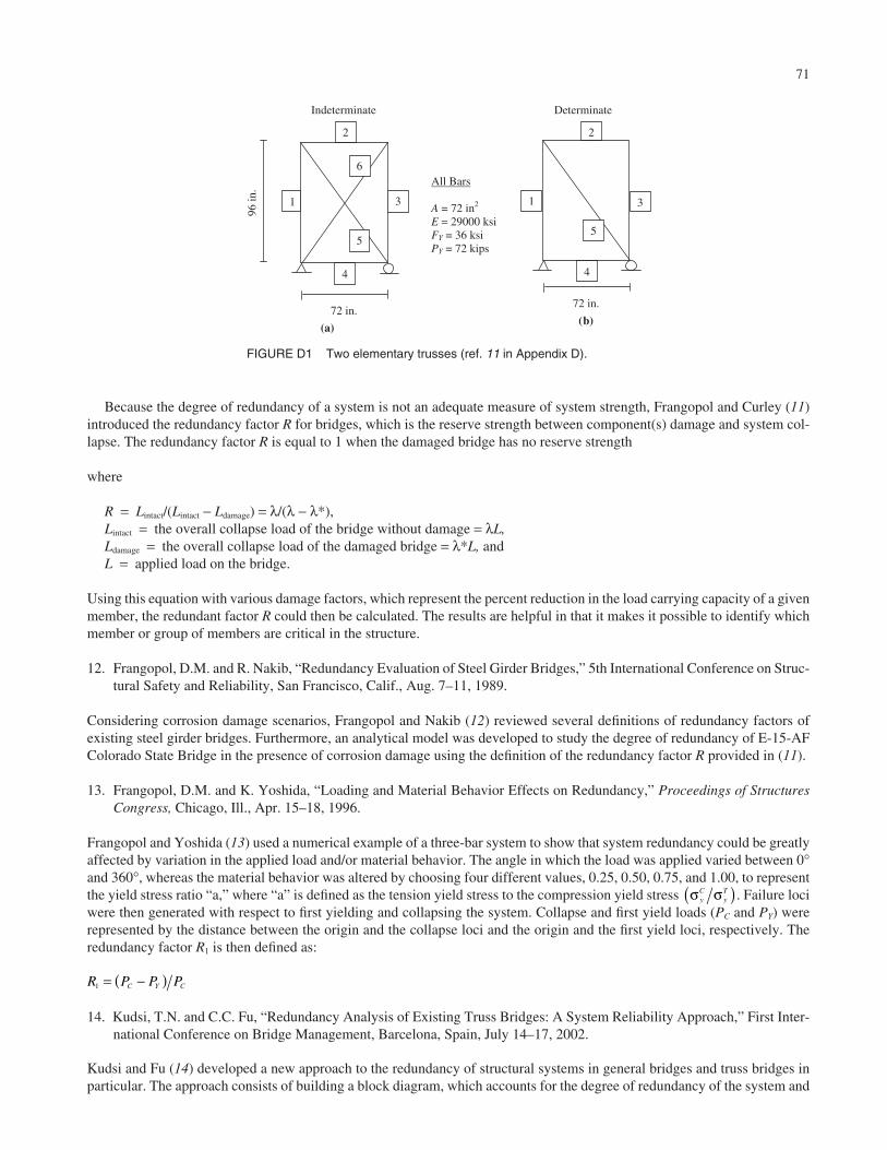
71
Because the degree of redundancy of a system is not an adequate measure of system strength, Frangopol and Curley (11)introduced the redundancy factor R for bridges, which is the reserve strength between component(s) damage and system col-lapse. The redundancy factor R is equal to 1 when the damaged bridge has no reserve strength
where
R = Lintact/(Lintact − Ldamage) = λ/(λ − λ*),Lintact = the overall collapse load of the bridge without damage = λL,Ldamage = the overall collapse load of the damaged bridge = λ*L, andL = applied load on the bridge.
Using this equation with various damage factors, which represent the percent reduction in the load carrying capacity of a givenmember, the redundant factor R could then be calculated. The results are helpful in that it makes it possible to identify whichmember or group of members are critical in the structure.
12. Frangopol, D.M. and R. Nakib, “Redundancy Evaluation of Steel Girder Bridges,” 5th International Conference on Struc-tural Safety and Reliability, San Francisco, Calif., Aug. 7–11, 1989.
Considering corrosion damage scenarios, Frangopol and Nakib (12) reviewed several definitions of redundancy factors ofexisting steel girder bridges. Furthermore, an analytical model was developed to study the degree of redundancy of E-15-AFColorado State Bridge in the presence of corrosion damage using the definition of the redundancy factor R provided in (11).
13. Frangopol, D.M. and K. Yoshida, “Loading and Material Behavior Effects on Redundancy,” Proceedings of StructuresCongress, Chicago, Ill., Apr. 15–18, 1996.
Frangopol and Yoshida (13) used a numerical example of a three-bar system to show that system redundancy could be greatlyaffected by variation in the applied load and/or material behavior. The angle in which the load was applied varied between 0°and 360°, whereas the material behavior was altered by choosing four different values, 0.25, 0.50, 0.75, and 1.00, to representthe yield stress ratio “a,” where “a” is defined as the tension yield stress to the compression yield stress . Failure lociwere then generated with respect to first yielding and collapsing the system. Collapse and first yield loads (PC and PY) wererepresented by the distance between the origin and the collapse loci and the origin and the first yield loci, respectively. Theredundancy factor R1 is then defined as:
14. Kudsi, T.N. and C.C. Fu, “Redundancy Analysis of Existing Truss Bridges: A System Reliability Approach,” First Inter-national Conference on Bridge Management, Barcelona, Spain, July 14–17, 2002.
Kudsi and Fu (14) developed a new approach to the redundancy of structural systems in general bridges and truss bridges inparticular. The approach consists of building a block diagram, which accounts for the degree of redundancy of the system and
R P P PC Y C1 = −( )
σ σyC
yT( )
Indeterminate Determinate
(b)
All Bars
A = 72 in2
E = 29000 ksi FY = 36 ksi PY = 72 kips
4
5
31
2
1
4
5
6
2
(a)
96 in
.
3
72 in. 72 in.
FIGURE D1 Two elementary trusses (ref. 11 in Appendix D).
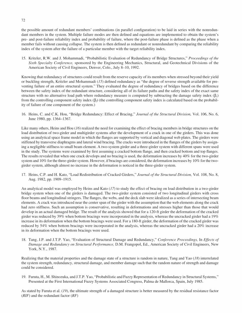
the possible amount of redundant members’ combinations (in parallel configuration) to be laid in series with the nonredun-dant members in the system. Multiple failure modes are then defined and equations are implemented to obtain the system’spre- and post-failure reliability index and probability of failure, where the post-failure phase is defined as the phase when amember fails without causing collapse. The system is then defined as redundant or nonredundant by comparing the reliabilityindex of the system after the failure of a particular member with the target reliability index.
15. Kritzler, R.W. and J. Mohammadi, “Probabilistic Evaluation of Redundancy of Bridge Structures,” Proceedings of theSixth Specialty Conference, sponsored by the Engineering Mechanics, Structural, and Geotechnical Divisions of theAmerican Society of Civil Engineers, Denver, Colo., July 8–10, 1992.
Knowing that redundancy of structures could result from the reserve capacity of its members when stressed beyond their yieldor buckling strength, Kritzler and Mohammadi (15) defined redundancy as “the degree of reverse strength available for pre-venting failure of an entire structural system.” They evaluated the degree of redundancy of bridges based on the differencebetween the safety index of the redundant structure, considering all of its failure paths and the safety index of the exact samestructure with no alternative load path where redundancy measure is computed by subtracting the damage safety index (βs)from the controlling component safety index (βf) (the controlling component safety index is calculated based on the probabil-ity of failure of one component of the system.)
16. Heins, C. and C.K. Hou, “Bridge Redundancy: Effect of Bracing,” Journal of the Structural Division, Vol. 106, No. 6,June 1980, pp. 1364–1367.
Like many others, Heins and Hou (16) realized the need for examining the effect of bracing members in bridge structures on theload distribution of two-girder and multigirder systems after the development of a crack in one of the girders. This was doneusing an analytical space frame model in which the flanges are supported by vertical and diagonal web plates. The girders werestiffened by transverse diaphragms and lateral wind bracing. The cracks were introduced in the flanges of the girders by assign-ing a negligible stiffness to small beam element. A two-system girder and a three-girder system with different spans were usedin the study. The systems were examined by first assuming a cracked bottom flange, and then cracked bottom and top flanges.The results revealed that when one crack develops and no bracing is used, the deformation increases by 40% for the two-girdersystem and 10% for the three-girder system. However, if bracings are considered, the deformation increases by 10% for the two-girder system, although almost no increase in the deformation is noticed in the three-girder system.
17. Heins, C.P. and H. Kato, “Load Redistribution of Cracked Girders,” Journal of the Structural Division, Vol. 108, No. 8,Aug. 1982, pp. 1909–1915.
An analytical model was employed by Heins and Kato (17) to study the effect of bracing on load distribution in a two-girderbridge system when one of the girders is damaged. The two-girder system consisted of two longitudinal girders with crossfloor beams and longitudinal stringers. The flanges, the webs, and the deck slab were idealized as a series of intersecting beamelements. A crack was introduced near the center span of the girder with the assumption that the web elements along the crackhad zero stiffness. Such an assumption is conservative, resulting in deformations and stresses higher than those that woulddevelop in an actual damaged bridge. The result of the analysis showed that for a 120-ft girder the deformation of the crackedgirder was reduced by 39% when bottom bracings were incorporated in the analysis, whereas the uncracked girder had a 19%increase in its deformation when the bottom bracings were used. For a 180-ft girder, the deformation of the cracked girder wasreduced by 54% when bottom bracings were incorporated in the analysis, whereas the uncracked girder had a 20% increasein its deformation when the bottom bracings were used.
18. Tang, J.P. and J.T.P. Yao, “Evaluation of Structural Damage and Redundancy,” Conference Proceedings, In Effects ofDamage and Redundancy on Structural Performance, D.M. Frangopol, Ed., American Society of Civil Engineers, NewYork, N.Y., 1987.
Realizing that the material properties and the damage state of a structure is random in nature, Tang and Yao (18) interrelatedthe system strength, redundancy, structural damage, and member damage such that the random nature of strength and damagecould be considered.
19. Furuta, H., M. Shinozuka, and J.T.P. Yao, “Probabilistic and Fuzzy Representation of Redundancy in Structural Systems,”Presented at the First International Fuzzy Systems Associated Congress, Palma de Mallorca, Spain, July 1985.
As stated by Furuta et al. (19), the ultimate strength of a damaged structure is better measured by the residual resistance factor(RIF) and the redundant factor (RF)
72

73
where
Xi = member properties of the ith member,Yj = reduction in geometry properties of the jth member (zero for undamaged structure), andAk = constant representing original geometrical properties of the kth member.
These equations assume that material properties, original geometry properties, and the damage level of a member areknown. However, because such information is difficult to obtain, Tang and Yao (18) considered a probabilistic approach andtreat some of the variables as random variables and define RIF and RF in the average sense
where
where E [.] denotes expected value.
20. Moses, F., “Evaluation of Bridge Safety and Remaining Life,” Conference Proceeding, In Structural Design, Analysis,and Testing, Alfred H.S. Ang, Ed., American Society of Civil Engineers, New York, N.Y., 1989, pp. 717–726.
Based on reliability principles and available data, Moses (20) considered the overstress limit state and the fatigue limit statefor the evaluation of bridges. The overstress limit state refers to the extreme event in which the maximum load effect exceedsthe bridge strength capacity. The fatigue limit state is determined by repetitive loading and is more sensitive in steel bridges.Provided that the bridge is redundant in which a multiload path exists in the bridge, a target reliability index of 2.3 was chosen
by the author. The reliability index b was calculated using the formula β = g_/σg, where g
_= mean safety margin, and σg = standard
deviation of g.
The value of g is calculated based on the safety index model:
where
R = member strength,D = dead load effect, andL = live load effect.
The statistical values of the load and load effects were assembled from weight-in-motion programs, field tests, and otherload meter information.
21. Ghosn, M. and F. Moses, NCHRP Report 406: Redundancy in Highway Bridge Superstructures, Transportation ResearchBoard, National Research Council, Washington, D.C., 1998, 50 pp.
In this report, Ghosn and Moses defined bridge redundancy as “the capability of bridge superstructure to continue to carry loadsafter the damage or the failure of one of its members.” They recognized that redundancy is related to system behavior ratherthan individual component behavior. The current bridge specifications, however, generally ignore the interaction between mem-
g R D L= − −
RFE R X A
E R X A E R X Y Au i k
u i k u i j k
=( )[ ]
( )[ ] − ( )[ ],
, , ,
RFE R X Y A
E R X Au i j k
u i k
= ( )[ ]( )[ ]
, ,
,
RFR X A
R X A R X Y A
R f X Y
u i k
u i k u i j k
u i j
=( )
( ) − ( )
=
,
, , ,
, ,, , , , , ,...A i j k mk( ) = 1 2 (ultimate strength of intact structure),
RIFR X Y A
R X Au i j k
u i k
= ( )( )
, ,
,
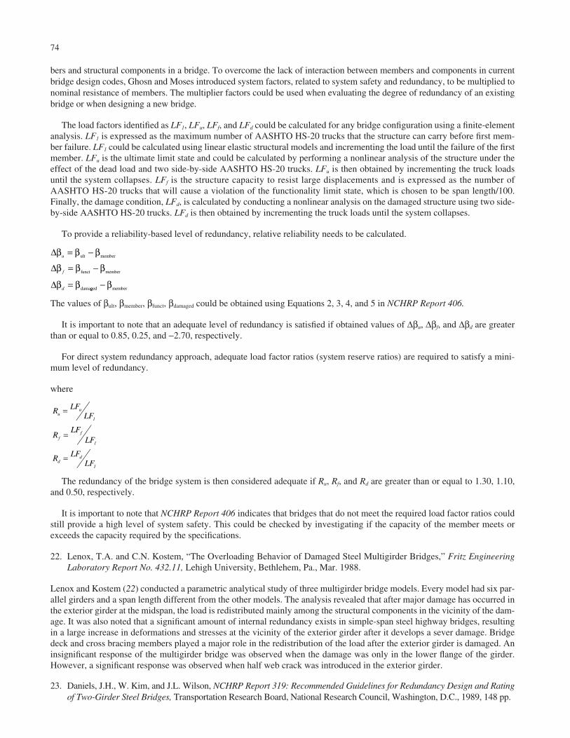
bers and structural components in a bridge. To overcome the lack of interaction between members and components in currentbridge design codes, Ghosn and Moses introduced system factors, related to system safety and redundancy, to be multiplied tonominal resistance of members. The multiplier factors could be used when evaluating the degree of redundancy of an existingbridge or when designing a new bridge.
The load factors identified as LF1, LFu, LFf, and LFd could be calculated for any bridge configuration using a finite-elementanalysis. LF1 is expressed as the maximum number of AASHTO HS-20 trucks that the structure can carry before first mem-ber failure. LF1 could be calculated using linear elastic structural models and incrementing the load until the failure of the firstmember. LFu is the ultimate limit state and could be calculated by performing a nonlinear analysis of the structure under theeffect of the dead load and two side-by-side AASHTO HS-20 trucks. LFu is then obtained by incrementing the truck loadsuntil the system collapses. LFf is the structure capacity to resist large displacements and is expressed as the number ofAASHTO HS-20 trucks that will cause a violation of the functionality limit state, which is chosen to be span length/100.Finally, the damage condition, LFd, is calculated by conducting a nonlinear analysis on the damaged structure using two side-by-side AASHTO HS-20 trucks. LFd is then obtained by incrementing the truck loads until the system collapses.
To provide a reliability-based level of redundancy, relative reliability needs to be calculated.
The values of βult, βmember, βfunct, βdamaged could be obtained using Equations 2, 3, 4, and 5 in NCHRP Report 406.
It is important to note that an adequate level of redundancy is satisfied if obtained values of Δβu, Δβf, and Δβd are greaterthan or equal to 0.85, 0.25, and −2.70, respectively.
For direct system redundancy approach, adequate load factor ratios (system reserve ratios) are required to satisfy a mini-mum level of redundancy.
where
The redundancy of the bridge system is then considered adequate if Ru, Rf, and Rd are greater than or equal to 1.30, 1.10,and 0.50, respectively.
It is important to note that NCHRP Report 406 indicates that bridges that do not meet the required load factor ratios couldstill provide a high level of system safety. This could be checked by investigating if the capacity of the member meets orexceeds the capacity required by the specifications.
22. Lenox, T.A. and C.N. Kostem, “The Overloading Behavior of Damaged Steel Multigirder Bridges,” Fritz EngineeringLaboratory Report No. 432.11, Lehigh University, Bethlehem, Pa., Mar. 1988.
Lenox and Kostem (22) conducted a parametric analytical study of three multigirder bridge models. Every model had six par-allel girders and a span length different from the other models. The analysis revealed that after major damage has occurred inthe exterior girder at the midspan, the load is redistributed mainly among the structural components in the vicinity of the dam-age. It was also noted that a significant amount of internal redundancy exists in simple-span steel highway bridges, resultingin a large increase in deformations and stresses at the vicinity of the exterior girder after it develops a sever damage. Bridgedeck and cross bracing members played a major role in the redistribution of the load after the exterior girder is damaged. Aninsignificant response of the multigirder bridge was observed when the damage was only in the lower flange of the girder.However, a significant response was observed when half web crack was introduced in the exterior girder.
23. Daniels, J.H., W. Kim, and J.L. Wilson, NCHRP Report 319: Recommended Guidelines for Redundancy Design and Ratingof Two-Girder Steel Bridges, Transportation Research Board, National Research Council, Washington, D.C., 1989, 148 pp.
R LFLF
RLF
LF
R LFLF
uu
ff
dd
=
=
=
1
1
1
Δ
Δ
Δ
β β β
β β β
β β
u
f
d
= −
= −
=
ult member
funct member
damagged member− β
74

75
Daniels et al. (23) provided guidelines for the design and rating of a redundant bracing system on new or existing two-girdersteel bridges. They also investigated the after-fracture redundancy of simple span and continuous, composite and noncom-posite, steel two-girder highway bridges. The investigation was done using an analytical model in which a near full-depth frac-ture was assumed to occur at any position along the length of one of the two girders. The fracture was introduced in the ten-sion flange and in the full depth of the web (no fracture of compression flange). The bridge system used in the model consistedof top and bottom bracings (laterals) and diaphragms.
The analysis concluded that significant redundancy could be achieved if redundant bracing systems (top and bottom later-als and diaphragms) are properly designed. Furthermore, if the bracing system is not originally designed for redundancy, thebridge system could still exhibit significant after-fracture redundancy if the bracing system is properly configured. Finally,there is a need for a new redundancy rating, which could be calculated by the allowable stress or load factor methods.
24. Chen, S.S., J.H. Daniels, and J.L. Wilson, “Computer Study of Redundancy of Single Span Welded Steel Two-GirderBridge,” Report FHWA-PA-85-047+84-20, Federal Highway Administration, Washington, D.C., Mar. 1986, 72 pp.
Chen et al. (24) investigated the response of a simple-span welded right two-girder bridge to a midspan fracture of one of thetwo main girders. The investigation included a three-dimensional model of the bridge to allow for the interaction between thestructural components.
The finite-element analyses confirmed the findings of many researchers, which is the critical role played by componentsand details in carrying the load after the fracture of one of the girders. For the bridge used in the study, under the dead load,the girder crack was followed by cracking and warping in the deck, failing of a fixed bearing, and buckling of several cross-frame horizontal members. Overall, a significant insight was gained on the structural behavior and the redistribution mecha-nism of the load after the through-depth fracture of one of the two girders at midspan.
25. “Final Report of the Bridge Safety Assurance Task Force to the New York State Commissioner of Transportation,” NewYork State Department of Transportation, John Kozak, Chairmen of the Bridge Safety Assurance Task Force, June 1995.
The Bridge Safety Assurance Task Force was formed primarily in response to the fatal collapses of Connecticut’s MianusRiver Bridge in 1983 and the New York State Thruway Schoharie Creek bridge collapse in 1987 as a result of scour. The taskforce included experts in various fields related to bridge engineering in the areas of hydraulics, river mechanics, concrete, andsteel. The individuals contributing in the area of steel bridges were Dr. John W. Fisher and Dr. J. Hartley Daniels. The reportevaluates conditions significantly affecting structural safety of New York bridges and recommends action to enhance identi-fication of vulnerable bridges and prioritization of corrective actions.
Vulnerability of steel bridges was examined and a procedure to assess vulnerability, based on average daily truck traffic,member type, susceptibility to fatigue, redundancy, and other factors were incorporated into the assessment procedure. Theresult of the assessment was a ranking that could be used to compare the vulnerability of a given bridge to other bridges andto permit more effective use of funds when considering which bridges to retrofit, repair, or replace.

Abbreviations used without definitions in TRB publications:
AASHO American Association of State Highway OfficialsAASHTO American Association of State Highway and Transportation OfficialsADA Americans with Disabilities ActAPTA American Public Transportation AssociationASCE American Society of Civil EngineersASME American Society of Mechanical EngineersASTM American Society for Testing and MaterialsATA American Trucking AssociationsCTAA Community Transportation Association of AmericaCTBSSP Commercial Truck and Bus Safety Synthesis ProgramDHS Department of Homeland SecurityDOE Department of EnergyEPA Environmental Protection AgencyFAA Federal Aviation AdministrationFHWA Federal Highway AdministrationFMCSA Federal Motor Carrier Safety AdministrationFRA Federal Railroad AdministrationFTA Federal Transit AdministrationIEEE Institute of Electrical and Electronics EngineersISTEA Intermodal Surface Transportation Efficiency Act of 1991ITE Institute of Transportation EngineersNASA National Aeronautics and Space AdministrationNCHRP National Cooperative Highway Research ProgramNCTRP National Cooperative Transit Research and Development ProgramNHTSA National Highway Traffic Safety AdministrationNTSB National Transportation Safety BoardSAE Society of Automotive EngineersSAFETEA-LU Safe, Accountable, Flexible, Efficient Transportation Equity Act: A Legacy for Users (2005)TCRP Transit Cooperative Research ProgramTEA-21 Transportation Equity Act for the 21st Century (1998)TRB Transportation Research BoardTSA Transportation Security AdministrationU.S.DOT United States Department of Transportation