nebraska department of roads construction...
TRANSCRIPT

Construction Stormwater Best Management Practices
Nebraska Department of Roads
First Edition
1
AcronymsBFM - Bonded Fiber Matrix
BMP – Best Management Practice
CSW – Construction Stormwater
ECB – Erosion Control Blanket
EPA – Environmental Protection Agency
MCM – Minimum Control Measure
NDEQ – Nebraska Department of Environmental Quality
NPDES – National Pollutant Discharge Elimination System
NOI – Notice of Intent
NOT – Notice of Termination
RECP - Rolled Erosion Control Products
SWPPP – Stormwater Pollution Prevention Plan
TRM – Turf Reinforcement Mat
This publication is funded in part by a Clean Water Act Section 319 grant from the US Environmental Protection Agency, through the Nebraska Department of Environmental Quality.
2
10 Keys to SucceedEvery construction project presents a unique set of pollution challenges for Owners and Operators to manage. Best Management Practices (BMPs) must be selected, designed, installed, and maintained correctly to minimize the risk of polluting water resources. Owners, Operators, and/or Inspectors utilize and inspect a variety of BMPs that work together during the project to control stormwater pollution. The following “10 Keys to Succeed” represent the best approaches to maintaining compliance with stormwater permit requirements and protecting water quality during construction.
Minimize soil disturbance and protect natural 1. features.
Phase construction activity in a manner that 2. minimizes impacts to resources.
Control stormwater quantity and velocity 3. fl owing onto and through the project.
Stabilize soils and protect slopes.4.
Protect storm drain inlets.5.
Establish perimeter controls.6.
Detain runoff, before it is discharged, to 7. provide time for sediment to settle out of suspension.
Establish stable construction exits.8.
Inspect and maintain all pollution control 9. measures.
Keep chemicals out of traffi c and 10. environmentally sensitive areas.

3
Contents
I. Project Administration . . . . . . . . . . . . . . . . . 5
A. Stormwater Permit Information . . . . . . . . . . . 6
B. SWPPP . . . . . . . . . . . . . . . . . . . . . . . . . . . . . . . 7
C. Qualifi cations . . . . . . . . . . . . . . . . . . . . . . . . . . 8
II. Erosion Control . . . . . . . . . . . . . . . . . . . . . . . 9
A. Mulching . . . . . . . . . . . . . . . . . . . . . . . . . . . . .10
B. Hydraulic Applications . . . . . . . . . . . . . . . . .121. Compost . . . . . . . . . . . . . . . . . . . . . . . . . . 122. Tackifi er. . . . . . . . . . . . . . . . . . . . . . . . . . . 123. Hydraulically Applied Mulches . . . . . . . . 134. Soil Binders . . . . . . . . . . . . . . . . . . . . . . . 14
C. Slope Interruption . . . . . . . . . . . . . . . . . . . . .161. Soil Roughening . . . . . . . . . . . . . . . . . . . . 172. Slope Tracking . . . . . . . . . . . . . . . . . . . . . 183. Berms & Diversions . . . . . . . . . . . . . . . . . 194. Benching . . . . . . . . . . . . . . . . . . . . . . . . . . 205. Temporary Slope Drains . . . . . . . . . . . . . 216. Wattles/Compost Logs . . . . . . . . . . . . . . 23
D. Vegetation . . . . . . . . . . . . . . . . . . . . . . . . . . .241. Cover Crop Seeding . . . . . . . . . . . . . . . . . 242. Temporary Seeding . . . . . . . . . . . . . . . . . 253. Permanent Seeding . . . . . . . . . . . . . . . . . 254. Sodding . . . . . . . . . . . . . . . . . . . . . . . . . . . 28
E. Rolled Erosion Control Products . . . . . . . . . .291. Straw . . . . . . . . . . . . . . . . . . . . . . . . . . . . . 292. Excelsior . . . . . . . . . . . . . . . . . . . . . . . . . . 293. Coconut Fiber . . . . . . . . . . . . . . . . . . . . . . 304. Combinations . . . . . . . . . . . . . . . . . . . . . . 305. Degradable Netting . . . . . . . . . . . . . . . . . 306. Turf Reinforcement Mat . . . . . . . . . . . . . 30
4
III. Sediment Control . . . . . . . . . . . . . . . . . . . .36
A. Erosion Checks . . . . . . . . . . . . . . . . . . . . . . .371. Wattles . . . . . . . . . . . . . . . . . . . . . . . . . . . 392. Earth Checks . . . . . . . . . . . . . . . . . . . . . . 403. Rock Checks . . . . . . . . . . . . . . . . . . . . . . . 414. Synthetic Checks . . . . . . . . . . . . . . . . . . . 42
B. Traps and Basins . . . . . . . . . . . . . . . . . . . . . .441. Silt Traps . . . . . . . . . . . . . . . . . . . . . . . . . . 442. Sediment Traps . . . . . . . . . . . . . . . . . . . . 453. Sediment Basins . . . . . . . . . . . . . . . . . . . 45
C. Barriers . . . . . . . . . . . . . . . . . . . . . . . . . . . . . .481. Topsoil . . . . . . . . . . . . . . . . . . . . . . . . . . . . 482. Mulch (Slash) . . . . . . . . . . . . . . . . . . . . . . 493. Silt Fence . . . . . . . . . . . . . . . . . . . . . . . . . 50
D. Inlet/Outlet Protection . . . . . . . . . . . . . . . . .541. Inlet Protection . . . . . . . . . . . . . . . . . . . . . 542. Outlet Protection . . . . . . . . . . . . . . . . . . . 58
IV. Good Housekeeping . . . . . . . . . . . . . . . . .60
A. Preservation of Vegetated Buffers . . . . . . .611. Environmentally Sensitive Areas . . . . . . 622. Construction Staging and Phasing . . . . . 62
B. Perimeter Control . . . . . . . . . . . . . . . . . . . . .631. Construction Safety Barrier Fencing . . . 632. Berms and Diversions . . . . . . . . . . . . . . . 64
C. Dust Control . . . . . . . . . . . . . . . . . . . . . . . . . .66
D. Stabilized Construction Exits . . . . . . . . . . . .67
E. Solid Waste Management . . . . . . . . . . . . . .69
F. Stockpiles . . . . . . . . . . . . . . . . . . . . . . . . . . . .71
G. Secondary Containment . . . . . . . . . . . . . . . .73
H. Concrete Washout . . . . . . . . . . . . . . . . . . . . .75
I. Street Sweeping & Vacuuming . . . . . . . . . .76
References & Acknowledgements . . . . . . . .77
I. Project Administration
5
I. Project Administration
Contents
A. Stormwater Permit Information . . . . . . . . . . . 6
B. SWPPP . . . . . . . . . . . . . . . . . . . . . . . . . . . . . . . 7
C. Qualifi cations . . . . . . . . . . . . . . . . . . . . . . . . . . 8
6
I. Project Administration
I. Project Administration
A. Stormwater Permit InformationDuring construction, stormwater Best Management Practices (BMPs) must be used that manage pollutants, such as sediment, that can impact water quality. When a construction project will disturb at least one acre of soil, with few exceptions, stormwater leaving the site is regulated. In Nebraska, the stormwater permitting program is administered by the Nebraska Department of Environmental Quality (NDEQ). The construction project Owner is responsible for applying for coverage and complying with all permit requirements. Both NDEQ and the U.S. Environmental Protection Agency (EPA) can take enforcement action against the project Owner, Operator, and any other responsible party for violating the required permit conditions. NDEQ’s General Construction Storm Water Permit can be viewed at: www.transportation.nebraska.gov
Regulated Waters of the State include “streams, lakes, ponds, impounding reservoirs, marshes, wetlands, watercourses, waterways, wells, springs, irrigation systems, drainage systems, and all other bodies or accumulation of water, surface and underground, natural or artifi cial, public or private, situated wholly or partly within or bordering upon the state.” Protecting these water resources is not only the right thing to do for the environment, it also protects human health and safety. Uncontrolled erosion during construction can cause large amounts of sediment to adversely impact streams, damage drainage structures, and cause public concern. Soil erosion, expensive maintenance efforts, and potential fi nes are avoided when BMPs are correctly designed, installed, and maintained.
I. Project Administration
7
B. SWPPPA Stormwater Pollution Prevention Plan (SWPPP) documents how stormwater run off—or discharge—from a construction site will be controlled. The construction project owner must develop a SWPPP before applying for coverage under the Nebraska General Construction Stormwater Permit. The SWPPP includes permanent and temporary erosion control plans, specifi cations and special provisions. The SWPPP describes erosion prevention measures, sediment controls, and good housekeeping practices that will be used to prevent construction-related pollutants from impacting water quality.
A SWPPP also addresses specifi c information for protecting water quality including a detailed description of the:
• potential construction-related pollutants,
• temporary and permanent BMPs,
• implementation sequence of BMPs,
• inspection and maintenance measures for BMPs,
• corrective actions and changes to the SWPPP.
Basic information and photos of good and poor BMP examples are included in this document to illustrate important aspects of many BMPs. Helpful information for developing and maintaining a SWPPP and Erosion Control Plan can be viewed at: www.transportation.nebraska.gov
8
I. Project Administration
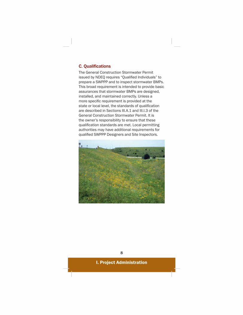
C. Qualifi cationsThe General Construction Stormwater Permit issued by NDEQ requires “Qualifi ed Individuals” to prepare a SWPPP and to inspect stormwater BMPs. This broad requirement is intended to provide basic assurances that stormwater BMPs are designed, installed, and maintained correctly. Unless a more specifi c requirement is provided at the state or local level, the standards of qualifi cation are described in Sections III.A.1 and III.I.3 of the General Construction Stormwater Permit. It is the owner’s responsibility to ensure that these qualifi cation standards are met. Local permitting authorities may have additional requirements for qualifi ed SWPPP Designers and Site Inspectors.
II. Erosion Control
9
II. Erosion Control
Contents
A. Mulching . . . . . . . . . . . . . . . . . . . . . . . . . . . . .10
B. Hydraulic Applications . . . . . . . . . . . . . . . . .121. Compost . . . . . . . . . . . . . . . . . . . . . . . . . . 122. Tackifi er. . . . . . . . . . . . . . . . . . . . . . . . . . . 123. Hydraulically Applied Mulches . . . . . . . . 134. Soil Binders . . . . . . . . . . . . . . . . . . . . . . . 14
C. Slope Interruption . . . . . . . . . . . . . . . . . . . . .161. Soil Roughening . . . . . . . . . . . . . . . . . . . . 172. Slope Tracking . . . . . . . . . . . . . . . . . . . . . 183. Berms & Diversions . . . . . . . . . . . . . . . . . 194. Benching . . . . . . . . . . . . . . . . . . . . . . . . . . 205. Temporary Slope Drains . . . . . . . . . . . . . 216. Wattles/Compost Logs . . . . . . . . . . . . . 23
D. Vegetation . . . . . . . . . . . . . . . . . . . . . . . . . . .241. Cover Crop Seeding . . . . . . . . . . . . . . . . . 242. Temporary Seeding . . . . . . . . . . . . . . . . . 253. Permanent Seeding . . . . . . . . . . . . . . . . . 254. Sodding . . . . . . . . . . . . . . . . . . . . . . . . . . . 28
E. Rolled Erosion Control Products . . . . . . . . . .291. Straw . . . . . . . . . . . . . . . . . . . . . . . . . . . . . 292. Excelsior . . . . . . . . . . . . . . . . . . . . . . . . . . 293. Coconut Fiber . . . . . . . . . . . . . . . . . . . . . . 304. Combinations . . . . . . . . . . . . . . . . . . . . . . 305. Degradable Netting . . . . . . . . . . . . . . . . . 306. Turf Reinforcement Mat . . . . . . . . . . . . . 30
II. Erosion Control
10
II. Erosion Control
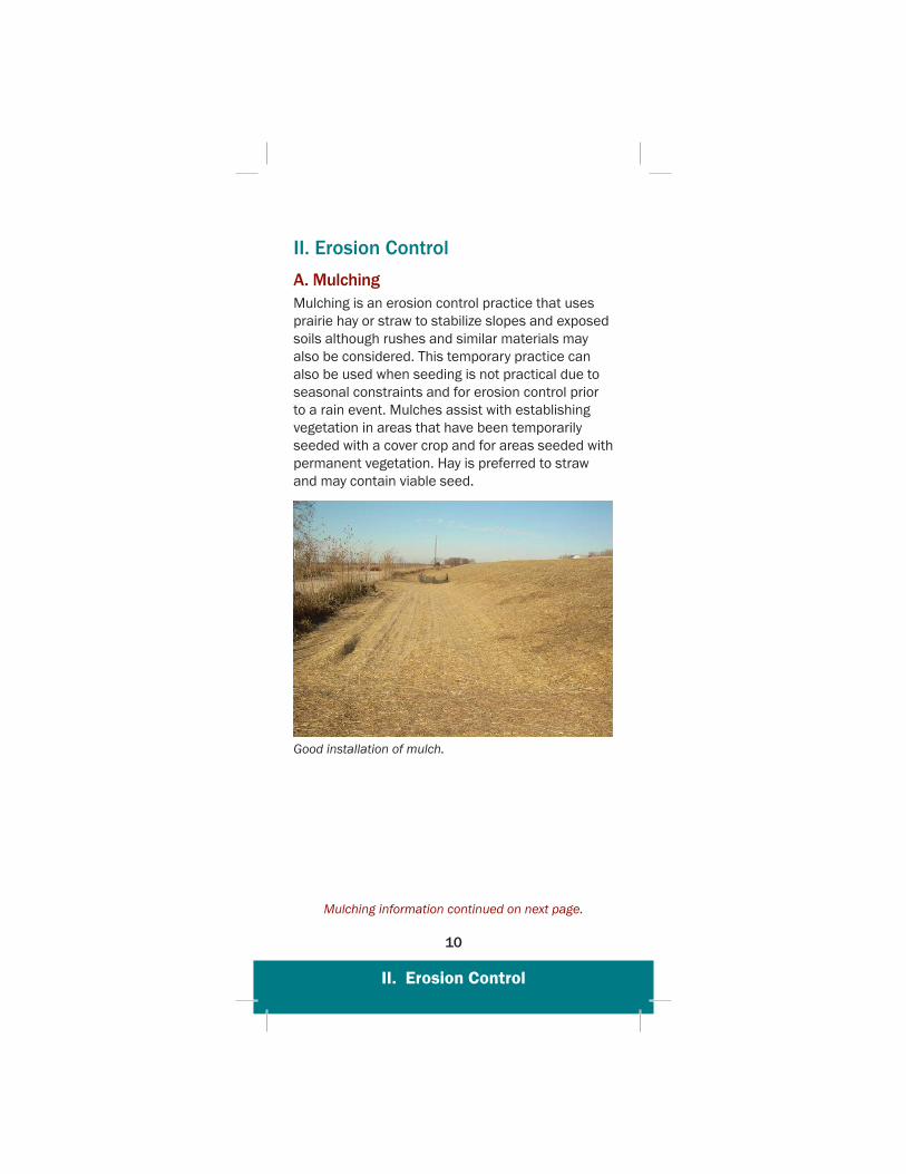
A. MulchingMulching is an erosion control practice that uses prairie hay or straw to stabilize slopes and exposed soils although rushes and similar materials may also be considered. This temporary practice can also be used when seeding is not practical due to seasonal constraints and for erosion control prior to a rain event. Mulches assist with establishing vegetation in areas that have been temporarily seeded with a cover crop and for areas seeded with permanent vegetation. Hay is preferred to straw and may contain viable seed.
Good installation of mulch.
Mulching information continued on next page.
II. Erosion Control
11
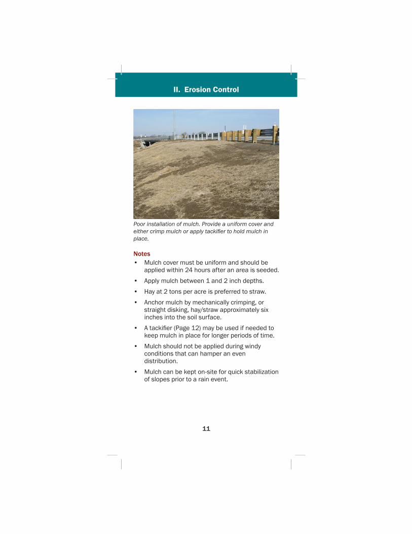
Poor installation of mulch. Provide a uniform cover and either crimp mulch or apply tackifi er to hold mulch in place.
Notes• Mulch cover must be uniform and should be
applied within 24 hours after an area is seeded.
• Apply mulch between 1 and 2 inch depths.
• Hay at 2 tons per acre is preferred to straw.
• Anchor mulch by mechanically crimping, or straight disking, hay/straw approximately six inches into the soil surface.
• A tackifi er (Page 12) may be used if needed to keep mulch in place for longer periods of time.
• Mulch should not be applied during windy conditions that can hamper an even distribution.
• Mulch can be kept on-site for quick stabilization of slopes prior to a rain event.

II. Erosion Control
12
B. Hydraulic ApplicationsSome erosion control materials can be applied to bare soil using hydraulic applications. These materials assist in establishing erosion-resistant vegetation on disturbed areas and critical slopes. A homogenous slurry of compost, tackifying agents, mulches and soil binders can be uniformly broadcast onto the soil. Hydraulic applications are effi cient because erosion and dust control materials can often be applied in one operation.
1. Compost Composts are engineered soil amendments made of solid organic materials that must meet local, state, and federal quality standards. Compost may be blown onto slopes as an alternative to placement of erosion control blankets. When properly applied, compost protects the soil and provides an organic growth medium to assist vegetation growth.
2. Tackifi erTackifi ers are bonding agents made of synthetic polymers used to stick, or tack, hydraulic seeding and hay or straw mulch to the soil surface. Wind can blow hay and straw away which allows precipitation to cause erosion. Tackifi ers provide immediate and extended protection from wind and rain to allow vegetation adequate time to establish.
Notes• Tackifi ers are water-soluble and must be
reapplied 6 to 12 months after application if plants have not germinated to stabilize the soil.
• Apply tackifi ers the same day as mulch is applied.
• Do not apply tackifi ers during precipitation events, over snow, or during periods of high winds.

II. Erosion Control
13
3. Hydraulically Applied MulchesThe use of hydraulically applied mulches is currently an evolving technology that seeks to improve functional longevity, erosion control effectiveness and vegetation establishment. Fiber Reinforced Matrix, Bonded Fiber Matrix, Stabilized Mulch Matrix, Hydraulic Mulch and other emerging products may be used when referring to this erosion control method. The benefi ts and considerations for hydraulically applied mulches are still being explored.
These products provide immediate erosion protection while creating an environment that promotes vegetation establishment. Products consist of various mixtures of refi ned fi ber matrices, tackifi ers, super-absorbents, fl occulating agents, man-made fi bers, plant biostimulants and other performance enhancing additives. Each product is unique and may last between 3-12 months before reapplication is needed. The Erosion Control Technology Council (ECTC) is researching and working to improve the specifi cations of these potentially valuable products.

II. Erosion Control
14
Place Hydraulically Applied Mulches uniformly over slopes from multiple angles to ensure proper adhesion to soil surfaces.
Notes• Avoid application if rain is forecasted since the
product must dry before controlling erosion.
• Concentrated fl ows can erode these products therefore application in channels is not ideal.
• Avoid vehicular or pedestrian traffi c. Once the surface is broken, the matrix material must be reapplied.
4. Soil Binders
Soil binders are chemical stabilizers, such as polyacrylamide, guar gum, and soybean oil, that provide temporary soil stabilization for stockpiles, berms, haul roads or when slopes cannot be seeded due to seasonal constraints. Soil binders are sprayed onto exposed soil surfaces to hold them in place and minimize wind and runoff erosion.
Soil Binders continued on next page.
II. Erosion Control
15
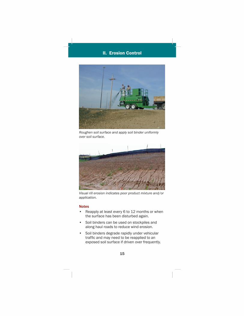
Roughen soil surface and apply soil binder uniformly over soil surface.
Visual rill erosion indicates poor product mixture and/or application.
Notes• Reapply at least every 6 to 12 months or when
the surface has been disturbed again.
• Soil binders can be used on stockpiles and along haul roads to reduce wind erosion.
• Soil binders degrade rapidly under vehicular traffi c and may need to be reapplied to an exposed soil surface if driven over frequently.
II. Erosion Control
16
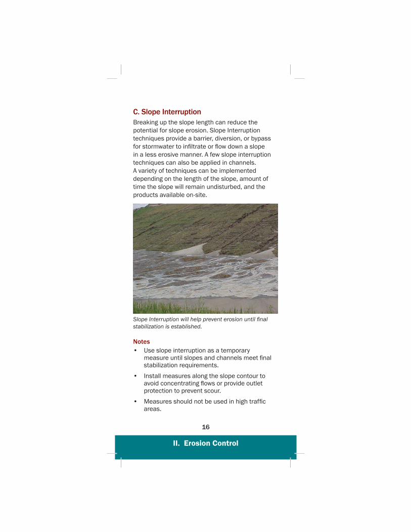
C. Slope InterruptionBreaking up the slope length can reduce the potential for slope erosion. Slope Interruption techniques provide a barrier, diversion, or bypass for stormwater to infi ltrate or fl ow down a slope in a less erosive manner. A few slope interruption techniques can also be applied in channels. A variety of techniques can be implemented depending on the length of the slope, amount of time the slope will remain undisturbed, and the products available on-site.
Slope Interruption will help prevent erosion until fi nal stabilization is established.
Notes• Use slope interruption as a temporary
measure until slopes and channels meet fi nal stabilization requirements.
• Install measures along the slope contour to avoid concentrating fl ows or provide outlet protection to prevent scour.
• Measures should not be used in high traffi c areas.
II. Erosion Control
17
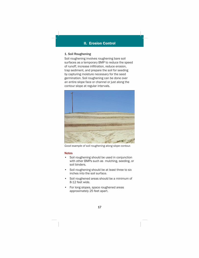
1. Soil RougheningSoil roughening involves roughening bare soil surfaces as a temporary BMP to reduce the speed of runoff, increase infi ltration, reduce erosion, trap sediment, and prepare the soil for seeding by capturing moisture necessary for the seed germination. Soil roughening can be done over an entire slope face or channel or just along the contour slope at regular intervals.
Good example of soil roughening along slope contour.
Notes• Soil roughening should be used in conjunction
with other BMPs such as mulching, seeding, or soil binders.
• Soil roughening should be at least three to six inches into the soil surface.
• Soil roughened areas should be a minimum of 8-12 feet wide.
• For long slopes, space roughened areas approximately 25 feet apart.
II. Erosion Control
18
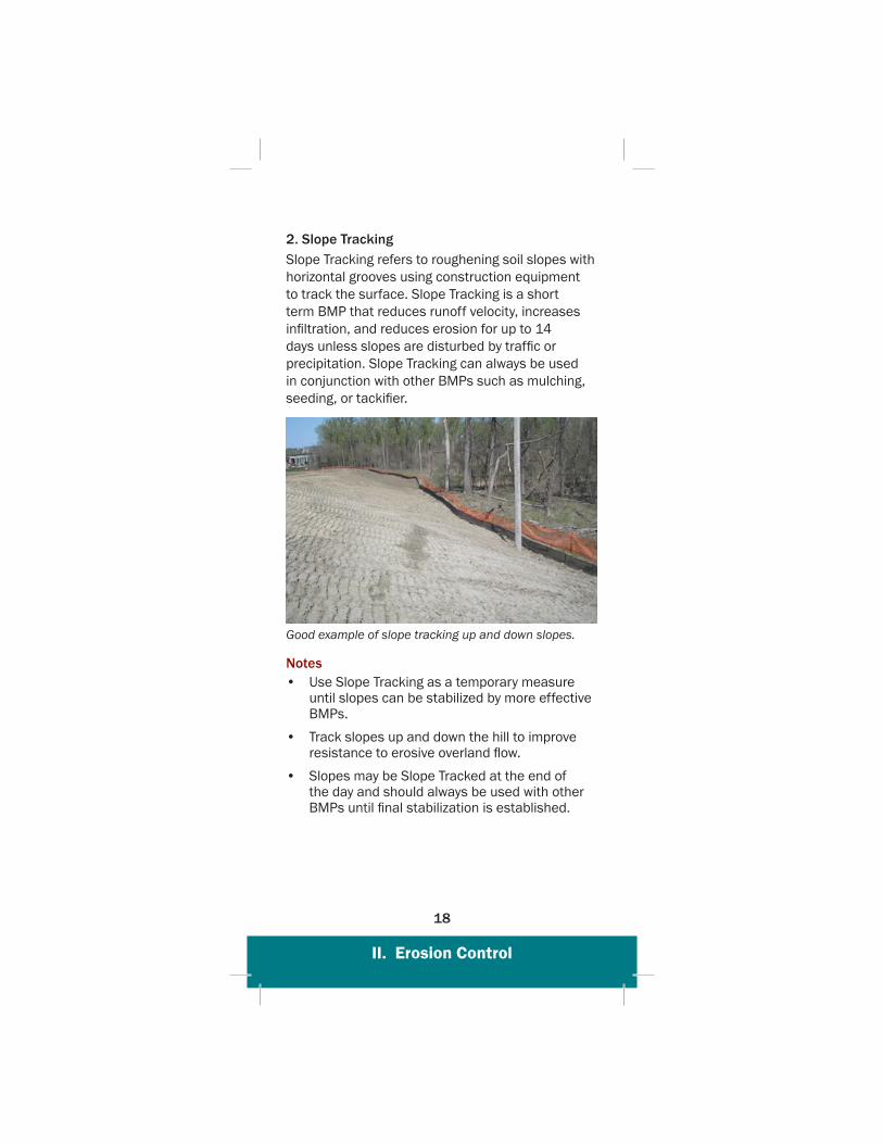
2. Slope TrackingSlope Tracking refers to roughening soil slopes with horizontal grooves using construction equipment to track the surface. Slope Tracking is a short term BMP that reduces runoff velocity, increases infi ltration, and reduces erosion for up to 14 days unless slopes are disturbed by traffi c or precipitation. Slope Tracking can always be used in conjunction with other BMPs such as mulching, seeding, or tackifi er.
Good example of slope tracking up and down slopes.
Notes• Use Slope Tracking as a temporary measure
until slopes can be stabilized by more effective BMPs.
• Track slopes up and down the hill to improve resistance to erosive overland fl ow.
• Slopes may be Slope Tracked at the end of the day and should always be used with other BMPs until fi nal stabilization is established.
II. Erosion Control
19
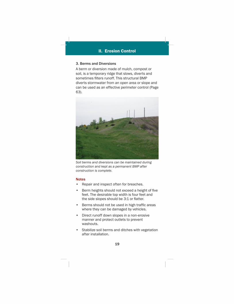
3. Berms and DiversionsA berm or diversion made of mulch, compost or soil, is a temporary ridge that slows, diverts and sometimes fi lters runoff. This structural BMP diverts stormwater from an open area or slope and can be used as an effective perimeter control (Page 63).
Soil berms and diversions can be maintained during construction and kept as a permanent BMP after construction is complete.
Notes• Repair and inspect often for breaches.
• Berm heights should not exceed a height of fi ve feet. The desirable top width is four feet and the side slopes should be 3:1 or fl atter.
• Berms should not be used in high traffi c areas where they can be damaged by vehicles.
• Direct runoff down slopes in a non-erosive manner and protect outlets to prevent washouts.
• Stabilize soil berms and ditches with vegetation after installation.
II. Erosion Control
20
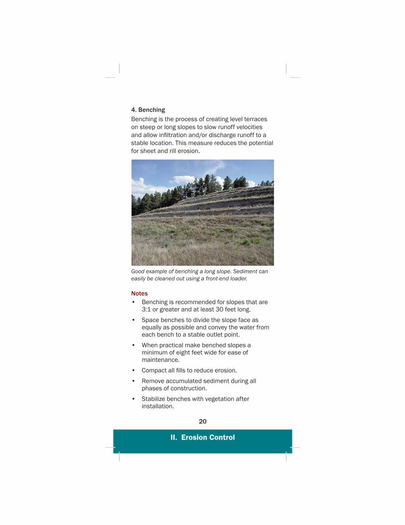
4. BenchingBenching is the process of creating level terraces on steep or long slopes to slow runoff velocities and allow infi ltration and/or discharge runoff to a stable location. This measure reduces the potential for sheet and rill erosion.
Good example of benching a long slope. Sediment can easily be cleaned out using a front-end loader.
Notes• Benching is recommended for slopes that are
3:1 or greater and at least 30 feet long.
• Space benches to divide the slope face as equally as possible and convey the water from each bench to a stable outlet point.
• When practical make benched slopes a minimum of eight feet wide for ease of maintenance.
• Compact all fi lls to reduce erosion.
• Remove accumulated sediment during all phases of construction.
• Stabilize benches with vegetation after installation.
II. Erosion Control
21
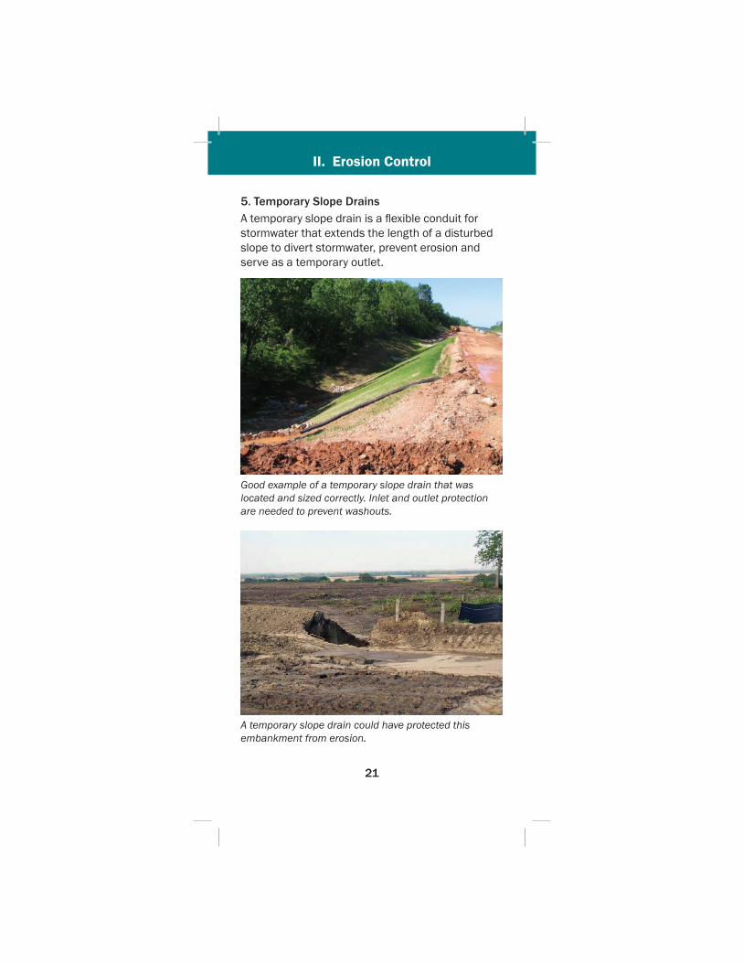
5. Temporary Slope DrainsA temporary slope drain is a fl exible conduit for stormwater that extends the length of a disturbed slope to divert stormwater, prevent erosion and serve as a temporary outlet.
Good example of a temporary slope drain that was located and sized correctly. Inlet and outlet protection are needed to prevent washouts.
A temporary slope drain could have protected this embankment from erosion.

II. Erosion Control
22
Slope drain using plastic pipe. Stake down securely, and install where heavy fl ows need to be transported down slopes. Be sure to stabilize the inlet and outlet.
Notes• Use during grading operations until fi nal
drainage structures are installed and slopes are stabilized.
• Direct stormwater to a temporary slope drain inlet using compacted berms and diversions (Page 19)
• Utilize fl exible pipe material that is at least 15 inches in diameter or larger.
• Fasten all connections with water tight fi ttings and securely anchor pipe to the slope.
• Adequate inlet and outlet protection must be installed to prevent scouring from erosive fl ows.
• Inlets and outlets may need to be cleaned out periodically and open chute protectors should not be undercut or bypassed.
II. Erosion Control
23
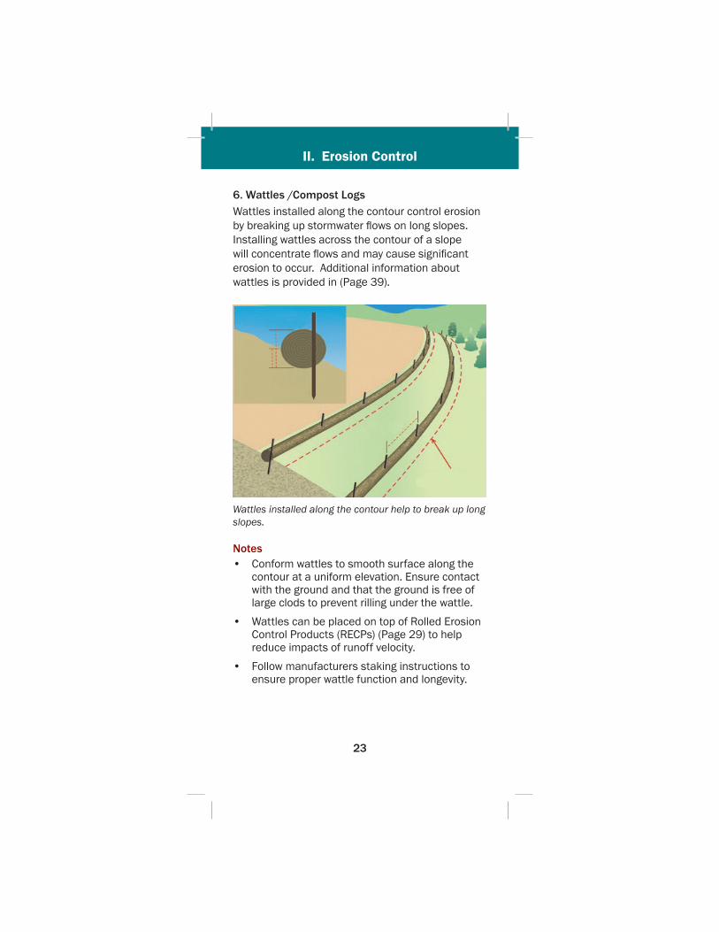
6. Wattles /Compost LogsWattles installed along the contour control erosion by breaking up stormwater fl ows on long slopes. Installing wattles across the contour of a slope will concentrate fl ows and may cause signifi cant erosion to occur. Additional information about wattles is provided in (Page 39).
Wattles installed along the contour help to break up long slopes.
Notes• Conform wattles to smooth surface along the
contour at a uniform elevation. Ensure contact with the ground and that the ground is free of large clods to prevent rilling under the wattle.
• Wattles can be placed on top of Rolled Erosion Control Products (RECPs) (Page 29) to help reduce impacts of runoff velocity.
• Follow manufacturers staking instructions to ensure proper wattle function and longevity.

II. Erosion Control
24
D. VegetationSeeding and sodding are the primary methods of establishing vegetation and stabilizing soils disturbed by construction activity. Vegetation is the most effective, long-term form of erosion control.
1. Cover Crop Seeding – Cover crop seeding is the establishment of a temporary vegetative cover on disturbed areas with appropriate, rapidly growing annual plants. Cover Crop seeding can be used on soil stockpiles, dikes, dams, sediment basin slopes, temporary road banks, or on fi nished grades that will be exposed for more than 14 days or until permanent seeding can be established.
NDOR Cover Crop Seed Selection Chart
* N
DOR
Spe
cifi c
Sel
ectio
n Ch
art

II. Erosion Control
25
2. Temporary Seeding – Temporary seeding is the establishment of annual or perennial vegetation using grasses for periods longer than cover crop seeding can protect. It is generally used in staged construction and can be in place for periods longer than a growing season.
3. Permanent Seeding – Permanent seeding is the primary method used to provide a permanent vegetative cover to protect against erosion. NDOR projects may specify different types of seeding and seed mixtures which are determined by regional growth conditions.
NDOR Seed TypesType A – Includes backslope, ditches, and portions
of the foreslope.
Type B – Includes shorter plant varieties placed on shoulder areas and in the medians which are frequently mowed.
Type C – Includes other seed mixtures as needed for special placement.
Good example of a mulched and seeded area.
II. Erosion Control
26
Notes• Prepare seed bed along the slope contour by
loosening soil surface to a minimum depth of three inches. Fertilizer should be applied after the seed bed is prepared.
• Mulch, mulch tackifi er and/or RECP should be applied as soon as possible after seeding.
• The area must be re-seeded if portions of it fail to establish, provide inadequate ground coverage, or are disturbed.
• Seeding should occur during the project as construction is completed and within the specifi ed time frame for seeding operations.
• Do not seed when the ground is frozen, wet or otherwise untillable, or when uniform distribution of seed cannot be achieved.
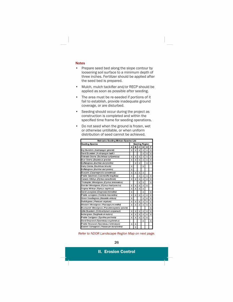
Refer to NDOR Landscape Region Map on next page.

II. Erosion Control
27
II. Erosion Control
28
4. Sodding – Sodding is a permanent erosion control practice that involves laying a continuous cover of grass sod on exposed soils. Sod provides immediate vegetative cover. Project specifi cations will dictate what times of the year sod should be laid.
Notes• Sod must be fertilized and treated for pre-
emergent weed control.
• A watering plan helps root systems grow and crowd out weed growth.
• Sod should be watered until moisture in the soil reaches 8-10 inches deep.
• For the fi rst two weeks new sod should be watered three times daily, during daylight hours to maintain soil moisture and watered routinely after that to maintain growth.
• Mowing is the responsibility of the property owner and new sod should not be mowed for 10-14 days after installation.
II. Erosion Control
29
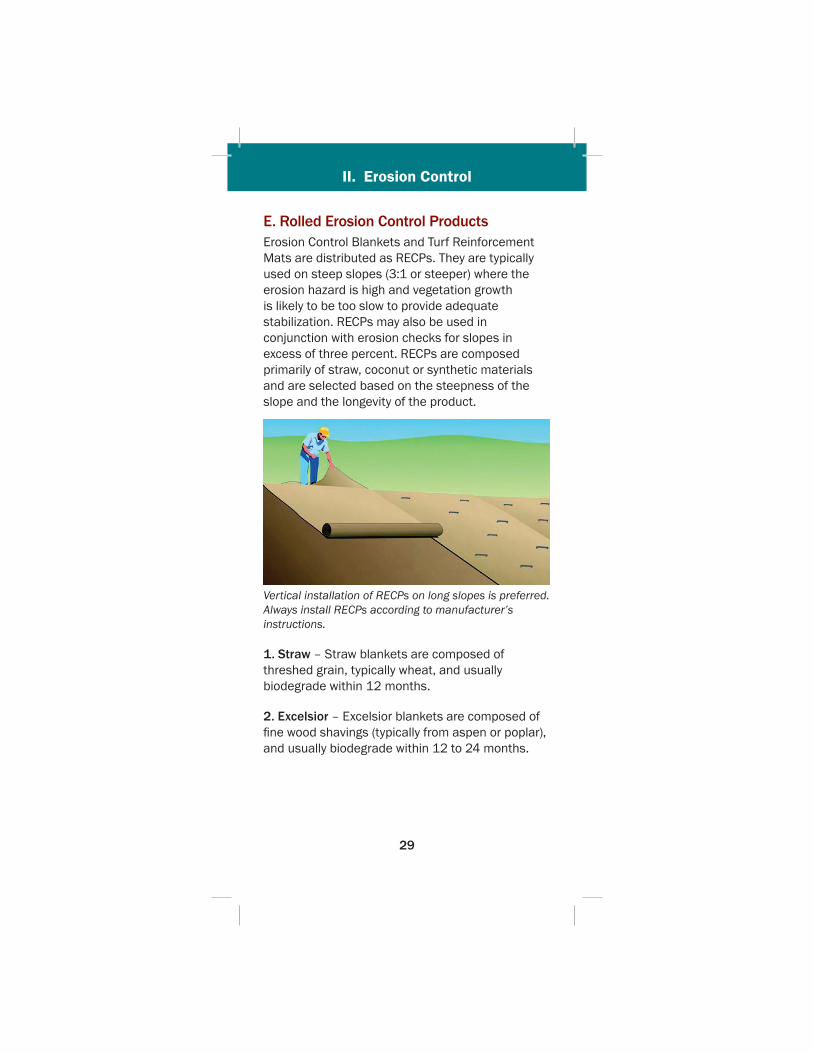
E. Rolled Erosion Control ProductsErosion Control Blankets and Turf Reinforcement Mats are distributed as RECPs. They are typically used on steep slopes (3:1 or steeper) where the erosion hazard is high and vegetation growth is likely to be too slow to provide adequate stabilization. RECPs may also be used in conjunction with erosion checks for slopes in excess of three percent. RECPs are composed primarily of straw, coconut or synthetic materials and are selected based on the steepness of the slope and the longevity of the product.
Vertical installation of RECPs on long slopes is preferred. Always install RECPs according to manufacturer’s instructions.
1. Straw – Straw blankets are composed of threshed grain, typically wheat, and usually biodegrade within 12 months.
2. Excelsior – Excelsior blankets are composed of fi ne wood shavings (typically from aspen or poplar), and usually biodegrade within 12 to 24 months.
II. Erosion Control
30
3. Coconut Fiber – Coconut fi ber blankets, also known as coir fi bers, hold up to eight times their weight in water and usually biodegrade within 36 months.
4. Combinations – Combination blankets composed of straw and coconut may be mixed in various ratios to improve the longevity of the blanket.
5. Degradable Netting - Degradable netting is a synthetic mesh or woven natural fi ber that is used on slopes to protect mulch from wind erosion.
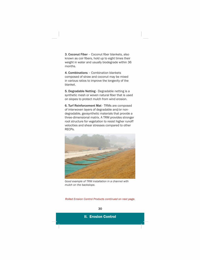
6. Turf Reinforcement Mat - TRMs are composed of interwoven layers of degradable and/or non-degradable, geosynthetic materials that provide a three-dimensional matrix. A TRM provides stronger root structure for vegetation to resist higher runoff velocities and shear stresses compared to other RECPs.
Good example of TRM installation in a channel with mulch on the backslope.
Rolled Erosion Control Products continued on next page.
II. Erosion Control
31
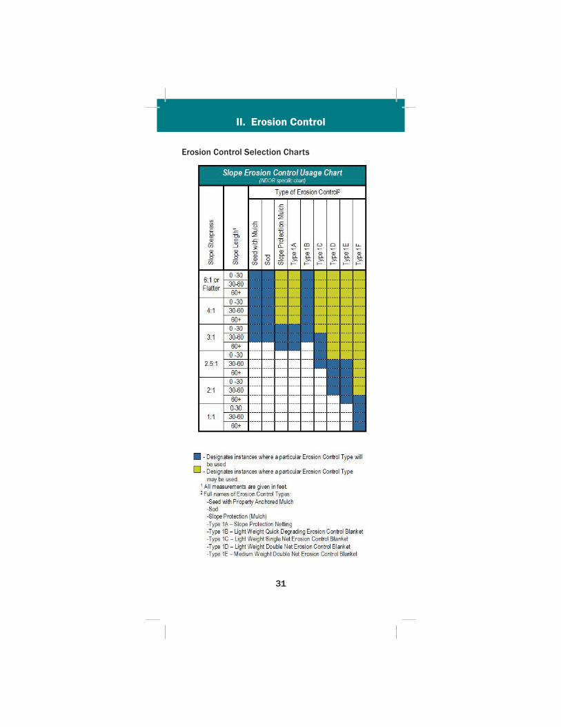
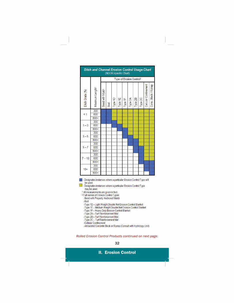
Erosion Control Selection Charts
II. Erosion Control
32
Rolled Erosion Control Products continued on next page.
II. Erosion Control
33
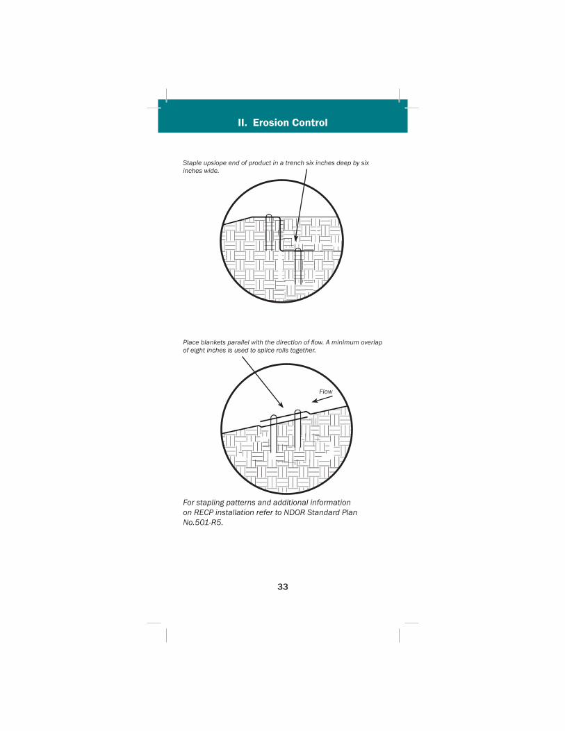
Staple upslope end of product in a trench six inches deep by six inches wide.
Place blankets parallel with the direction of fl ow. A minimum overlap of eight inches is used to splice rolls together.
Flow
For stapling patterns and additional information on RECP installation refer to NDOR Standard Plan No.501-R5.
II. Erosion Control
34
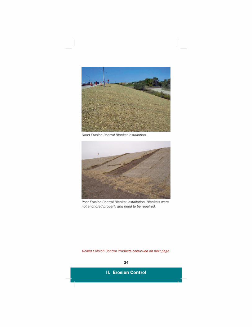
Good Erosion Control Blanket installation.
Poor Erosion Control Blanket installation. Blankets were not anchored properly and need to be repaired.
Rolled Erosion Control Products continued on next page.
II. Erosion Control
35
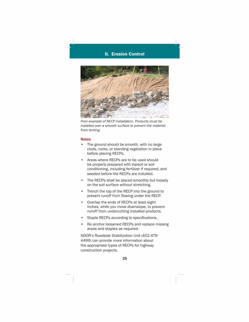
Poor example of RECP installation. Products must be installed over a smooth surface to prevent the material from tenting.
Notes• The ground should be smooth, with no large
clods, rocks, or standing vegetation in place before placing RECPs.
• Areas where RECPs are to be used should be properly prepared with topsoil or soil conditioning, including fertilizer if required, and seeded before the RECPs are installed.
• The RECPs shall be placed smoothly but loosely on the soil surface without stretching.
• Trench the top of the RECP into the ground to prevent runoff from fl owing under the RECP.
• Overlap the ends of RECPs at least eight inches, while you move downslope, to prevent runoff from undercutting installed products.
• Staple RECPs according to specifi cations.
• Re-anchor loosened RECPs and replace missing areas and staples as required.
NDOR’s Roadside Stabilization Unit (402-479-4499) can provide more information about the appropriate types of RECPs for highway construction projects.
3636
III. Sediment Control
Contents
A. Erosion Checks . . . . . . . . . . . . . . . . . . . . . . . .371. Wattles . . . . . . . . . . . . . . . . . . . . . . . . . . . 392. Earth Checks . . . . . . . . . . . . . . . . . . . . . . 403. Rock Checks . . . . . . . . . . . . . . . . . . . . . . . 414. Synthetic Checks . . . . . . . . . . . . . . . . . . . 42
B. Traps and Basins . . . . . . . . . . . . . . . . . . . . . .441. Silt Traps . . . . . . . . . . . . . . . . . . . . . . . . . . 442. Sediment Traps . . . . . . . . . . . . . . . . . . . . 453. Sediment Basins . . . . . . . . . . . . . . . . . . . 45
C. Barriers . . . . . . . . . . . . . . . . . . . . . . . . . . . . . .481. Topsoil . . . . . . . . . . . . . . . . . . . . . . . . . . . . 482. Mulch (Slash) . . . . . . . . . . . . . . . . . . . . . . 493. Silt Fence . . . . . . . . . . . . . . . . . . . . . . . . . 50
D. Inlet/Outlet Protection . . . . . . . . . . . . . . . . .541. Inlet Protection . . . . . . . . . . . . . . . . . . . . . 542. Outlet Protection . . . . . . . . . . . . . . . . . . . 58
III. Sediment Control
III. Sediment Control
37
III. Sediment Control
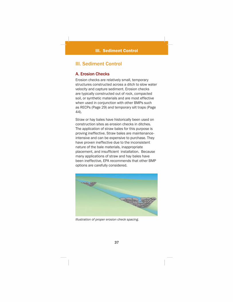
A. Erosion ChecksErosion checks are relatively small, temporary structures constructed across a ditch to slow water velocity and capture sediment. Erosion checks are typically constructed out of rock, compacted soil, or synthetic materials and are most effective when used in conjunction with other BMPs such as RECPs (Page 29) and temporary silt traps (Page 44).
Straw or hay bales have historically been used on construction sites as erosion checks in ditches. The application of straw bales for this purpose is proving ineffective. Straw bales are maintenance-intensive and can be expensive to purchase. They have proven ineffective due to the inconsistent nature of the bale materials, inappropriate placement, and insuffi cient installation. Because many applications of straw and hay bales have been ineffective, EPA recommends that other BMP options are carefully considered.
Illustration of proper erosion check spacing.
III. Sediment Control
38
Notes• Temporary checks should be removed when
their useful life has been completed. The useful life of an erosion check is complete when the check cannot be cleaned out and has become ineffective.
• Space erosion checks where the top elevation of the downstream check is level with the base elevation of the up stream check for maximum effectiveness.
• In the case of grass-lined ditches, checks should be removed when the grass has matured suffi ciently to protect the ditch or swale from erosion.
• The area beneath the check should be seeded and mulched immediately after the checks are removed.
• Erosion checks should be cleaned out once sediment has accumulated to half the height of the check material.
• Inspect for erosion along the ends of the checks and make repairs before the next inspection or rain event.
III. Sediment Control
39
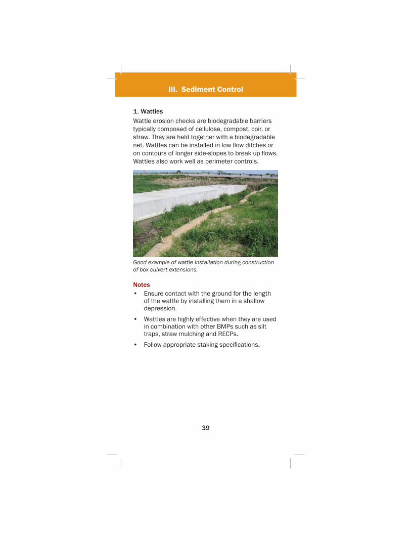
1. WattlesWattle erosion checks are biodegradable barriers typically composed of cellulose, compost, coir, or straw. They are held together with a biodegradable net. Wattles can be installed in low fl ow ditches or on contours of longer side-slopes to break up fl ows. Wattles also work well as perimeter controls.
Good example of wattle installation during construction of box culvert extensions.
Notes• Ensure contact with the ground for the length
of the wattle by installing them in a shallow depression.
• Wattles are highly effective when they are used in combination with other BMPs such as silt traps, straw mulching and RECPs.
• Follow appropriate staking specifi cations.
III. Sediment Control
40
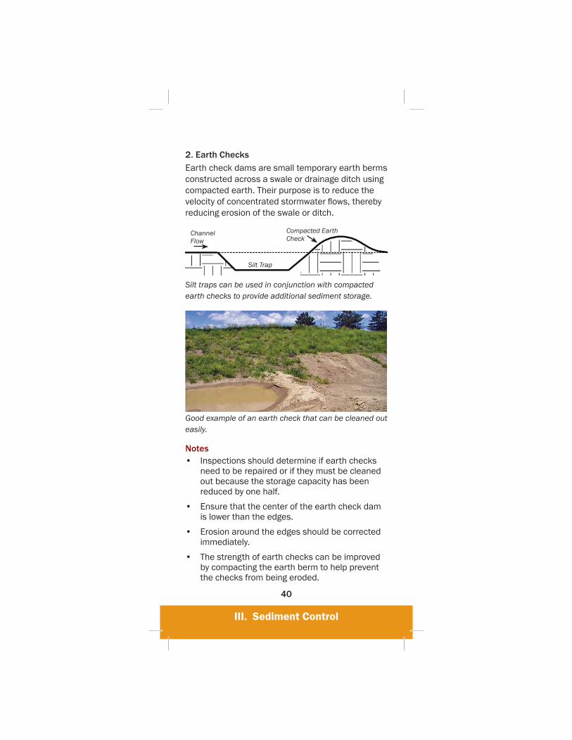
2. Earth ChecksEarth check dams are small temporary earth berms constructed across a swale or drainage ditch using compacted earth. Their purpose is to reduce the velocity of concentrated stormwater fl ows, thereby reducing erosion of the swale or ditch.
Channel Flow
Silt Trap
Compacted Earth Check
Silt traps can be used in conjunction with compacted earth checks to provide additional sediment storage.
Good example of an earth check that can be cleaned out easily.
Notes• Inspections should determine if earth checks
need to be repaired or if they must be cleaned out because the storage capacity has been reduced by one half.
• Ensure that the center of the earth check dam is lower than the edges.
• Erosion around the edges should be corrected immediately.
• The strength of earth checks can be improved by compacting the earth berm to help prevent the checks from being eroded.
III. Sediment Control
41
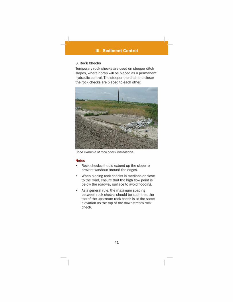
3. Rock ChecksTemporary rock checks are used on steeper ditch slopes, where riprap will be placed as a permanent hydraulic control. The steeper the ditch the closer the rock checks are placed to each other.
Good example of rock check installation.
Notes• Rock checks should extend up the slope to
prevent washout around the edges.
• When placing rock checks in medians or close to the road, ensure that the high fl ow point is below the roadway surface to avoid fl ooding.
• As a general rule, the maximum spacing between rock checks should be such that the toe of the upstream rock check is at the same elevation as the top of the downstream rock check.

III. Sediment Control
42
4. Synthetic ChecksSynthetic checks, such as triangular silt barriers, are typically used as temporary controls for ditch and channel stabilization during construction. These products are made of synthetic materials and are designed so that they can be relocated throughout the project as needed to control silt.
Upstream toe must be trenched 3-6”, backfi lled, and tamped down.
Install staples according to manufacturer’s specifi cations.
Standard synthetic checks will be 16-20” wide and 8-10” tall.
Channel Flow
Side cross section illustration of Synthetic Check installation.
Cross section width of synthetic check will provide a minimum overfl ow height of six inches for channel fl ow.
Front cross section illustration of Synthetic Check installation.
Synthetic Checks continued on next page.
III. Sediment Control
43
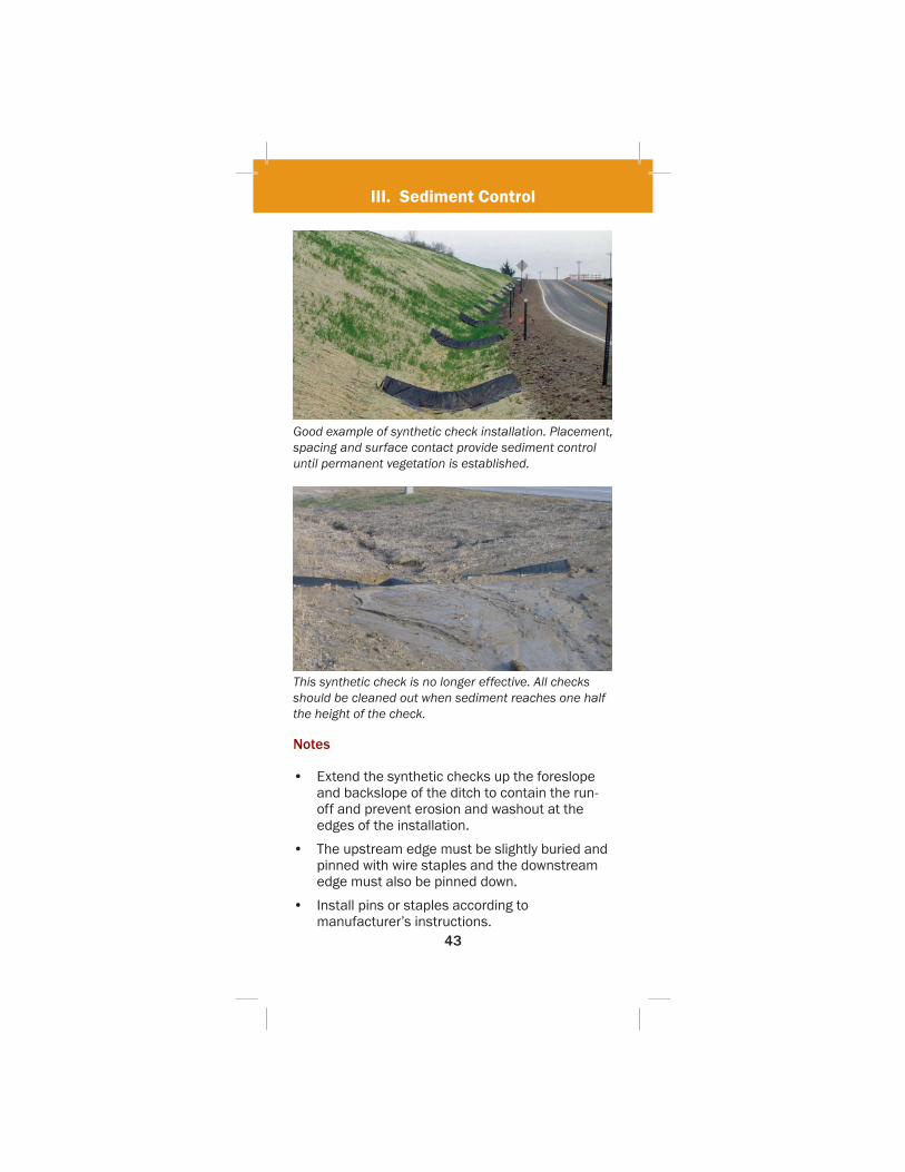
Good example of synthetic check installation. Placement, spacing and surface contact provide sediment control until permanent vegetation is established.
This synthetic check is no longer effective. All checks should be cleaned out when sediment reaches one half the height of the check.
Notes
• Extend the synthetic checks up the foreslope and backslope of the ditch to contain the run-off and prevent erosion and washout at the edges of the installation.
• The upstream edge must be slightly buried and pinned with wire staples and the downstream edge must also be pinned down.
• Install pins or staples according to manufacturer’s instructions.
III. Sediment Control
44
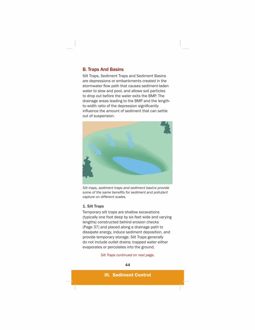
B. Traps And BasinsSilt Traps, Sediment Traps and Sediment Basins are depressions or embankments created in the stormwater fl ow path that causes sediment-laden water to slow and pool, and allows soil particles to drop out before the water exits the BMP. The drainage areas leading to the BMP and the length-to-width ratio of the depression signifi cantly infl uence the amount of sediment that can settle out of suspension.
Silt traps, sediment traps and sediment basins provide some of the same benefi ts for sediment and pollutant capture on different scales.
1. Silt Traps Temporary silt traps are shallow excavations (typically one foot deep by six feet wide and varying lengths) constructed behind erosion checks (Page 37) and placed along a drainage path to dissipate energy, induce sediment deposition, and provide temporary storage. Silt Traps generally do not include outlet drains; trapped water either evaporates or percolates into the ground.
Silt Traps continued on next page.

III. Sediment Control
45
Good example of a silt trap used in the right-of-way.
2. Sediment Traps Sediment Traps are small impoundments placed in a drainage path that serves one or more common drainage locations. They are typically a deeper excavation (three to four feet depth) placed behind an embankment. Sediment traps are sized to detain/retain the fi rst inch of runoff and induce sediment deposition. They are designed to handle drainage areas up to fi ve acres with large storms fl owing out through a stabilized outlet.
3. Sediment Basins Sediment basins are larger impoundments placed in or adjacent to a drainage path that serves several common drainage locations. They should be located at low lying areas of the site where fl ows converge. They are designed by a hydraulic engineer and can be either excavations, embankments, or a combination of both. Sediment basins are sized to detain/retain up to the 10-year, 24-hour storm event for sites that exceed fi ve acres in drainage area. They are designed to both induce sediment deposition and reduce peak discharges. They will have both primary and secondary stabilized outlets.

III. Sediment Control
46
Sediment traps and basins must be designed with an adequate overfl ow structure and outlet protection.
Good example of a constructed sediment basin for a linear construction project.
Traps and Basins continued on next page.

III. Sediment Control
47
Notes• Install sediment traps and basins before any
land disturbance takes place in the drainage area. Install silt traps as needed during construction.
• Sediment must be removed from the trap and basin when the storage volume has been reduced by one half.
• Sediment traps and basins should provide 3,600 cubic feet of storage per acre of disturbed area.
• The outlet of a sediment basin must be underlaid with geotextile and be at least one and one-half foot high and be designed to control overfl ow.
• Sediment basin outlets may be made up of both coarse aggregate and riprap.
• Sediment basins, sediment traps and silt traps are not intended for installation in creeks or other areas of major fl ow.

III. Sediment Control
48
C. BarriersInstalling stormwater barriers is a practice used to slow down runoff and allow sediment to settle out. Barriers are not intended to wrap the project site. Instead they provide small areas for containment of stormwater. Stormwater fl ows are either contained behind the barrier or allowed to pass over the top of them. Barriers are not installed along steep slopes or in channels like slope interruption (Page 16) techniques. Barriers function best when controlling sheet fl ow below the toe of a slope, adjacent to stream banks, and around storm drain inlets located in a recessed slump.
1. TopsoilProtecting and preserving topsoil is also a good BMP. Compacted topsoil can be used as a temporary barrier around the construction site and then re-applied during fi nal grading. Topsoil barriers must be stabilized if they will be left undisturbed for more than 14 days.
Topsoil can be used as a perimeter control during construction and reapplied as a growth medium during fi nal grading.
III. Sediment Control
49
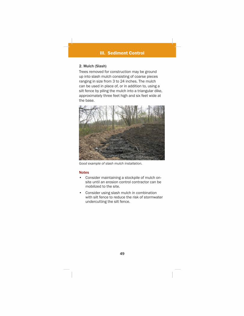
2. Mulch (Slash)Trees removed for construction may be ground up into slash mulch consisting of coarse pieces ranging in size from 3 to 24 inches. The mulch can be used in place of, or in addition to, using a silt fence by piling the mulch into a triangular dike, approximately three feet high and six feet wide at the base.
Good example of slash mulch installation.
Notes• Consider maintaining a stockpile of mulch on-
site until an erosion control contractor can be mobilized to the site.
• Consider using slash mulch in combination with silt fence to reduce the risk of stormwater undercutting the silt fence.
III. Sediment Control
50
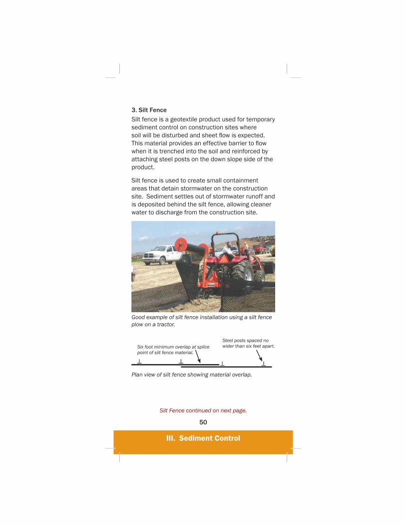
3. Silt FenceSilt fence is a geotextile product used for temporary sediment control on construction sites where soil will be disturbed and sheet fl ow is expected. This material provides an effective barrier to fl ow when it is trenched into the soil and reinforced by attaching steel posts on the down slope side of the product.
Silt fence is used to create small containment areas that detain stormwater on the construction site. Sediment settles out of stormwater runoff and is deposited behind the silt fence, allowing cleaner water to discharge from the construction site.
Good example of silt fence installation using a silt fence plow on a tractor.
Plan view of silt fence showing material overlap.
Silt Fence continued on next page.
Six foot minimum overlap at splice point of silt fence material.
Steel posts spaced no wider than six feet apart.

III. Sediment Control
51
Illustration of silt fence installation. Silt fence should be properly trenched to prevent undercutting. Trenching is not required if a silt fence plow is used for installation.
Poor example of silt fence installation. The silt fence was not trenched into the soil.

III. Sediment Control
52
Good silt fence installation. Accumulated sediment has been removed from the fence and the area has been mulched.
Poor example of silt fence use. Excessive quantities do not provide additional benefi ts and waste project resources.
Silt Fence continued on next page.
III. Sediment Control
53
Notes• Silt fence should be installed prior to any
grubbing or grading activity.
• Install along contours to avoid concentrated fl ows.
• Inspect silt fence regularly for sediment accumulation, tears, undermining, and separation from posts.
• Silt fence should be installed approximately six feet away from the toe of the fi ll, when feasible, for ease of maintenance.
• Sediment should be removed when it accumulates to one third of the exposed fabric height and be disposed of properly.
• Maximum drainage area is one-quarter acre per 100 feet of silt fence length.
• Silt fence should be removed once it has served its purpose and the area has been stabilized.
• Reinforce silt fence material with steel posts that are spaced no wider than six feet apart.
• Do not excavate silt fence trenches wider or deeper than necessary for installation and compact soil around the toe of the material.
III. Sediment Control
54
D. Inlet/Outlet ProtectionCulverts and ditches are designed to carry moderate to large amounts of stormwater. They also can carry sediment to streams, rivers, wetlands, lakes and sensitive areas if they are not properly protected. Culvert and swale outlets can become severely eroded if stormwater fl ows are not controlled.
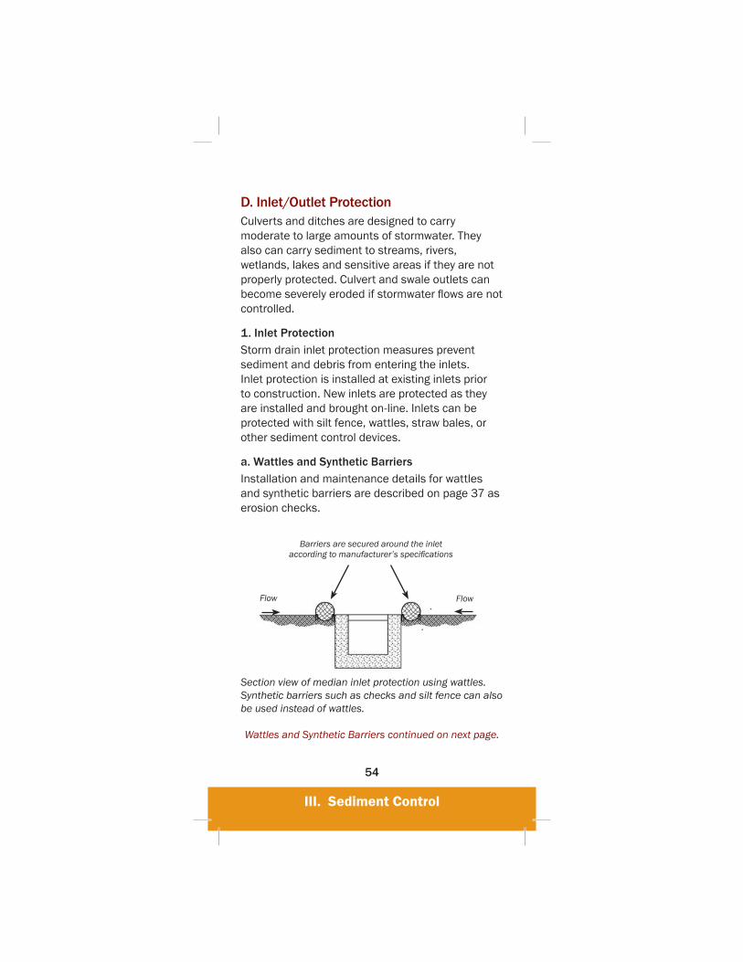
1. Inlet ProtectionStorm drain inlet protection measures prevent sediment and debris from entering the inlets. Inlet protection is installed at existing inlets prior to construction. New inlets are protected as they are installed and brought on-line. Inlets can be protected with silt fence, wattles, straw bales, or other sediment control devices.
a. Wattles and Synthetic BarriersInstallation and maintenance details for wattles and synthetic barriers are described on page 37 as erosion checks.
Barriers are secured around the inlet according to manufacturer’s specifi cations
Flow Flow
Section view of median inlet protection using wattles. Synthetic barriers such as checks and silt fence can also be used instead of wattles.
Wattles and Synthetic Barriers continued on next page.
III. Sediment Control
55
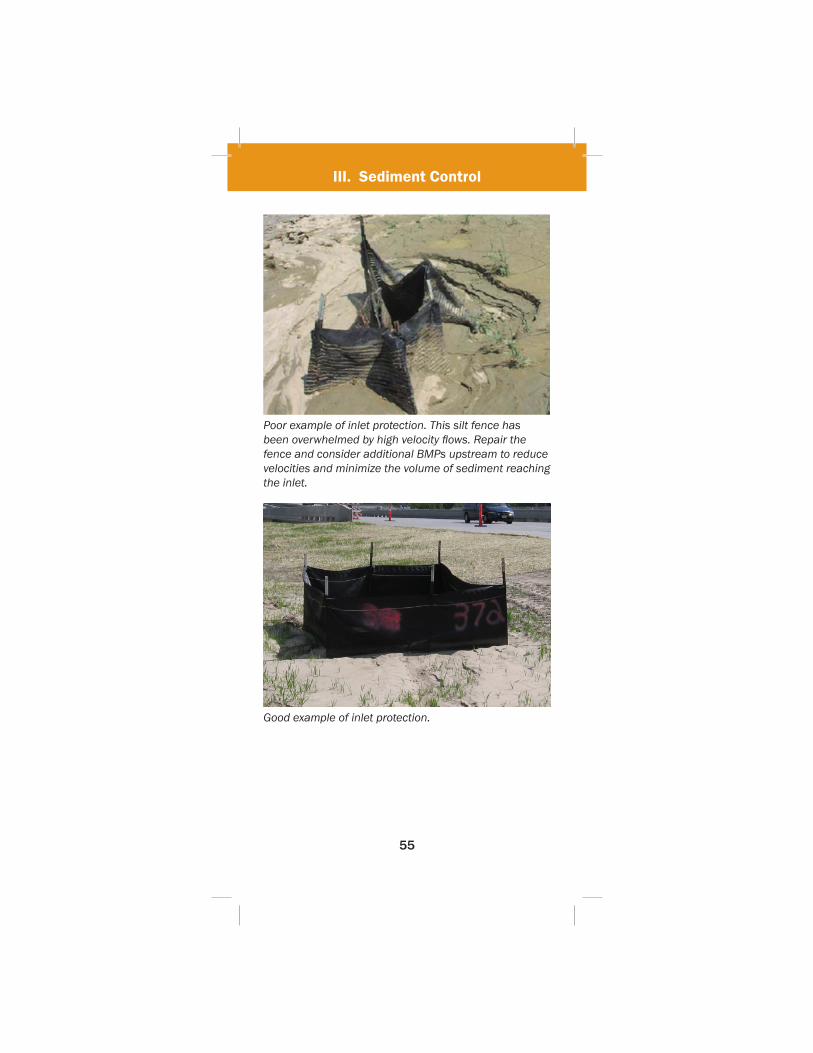
Poor example of inlet protection. This silt fence has been overwhelmed by high velocity fl ows. Repair the fence and consider additional BMPs upstream to reduce velocities and minimize the volume of sediment reaching the inlet.
Good example of inlet protection.
III. Sediment Control
56
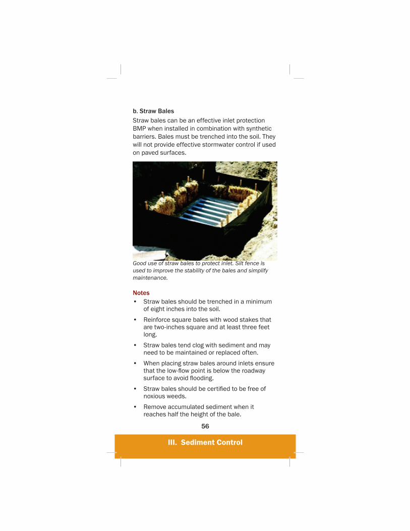
b. Straw BalesStraw bales can be an effective inlet protection BMP when installed in combination with synthetic barriers. Bales must be trenched into the soil. They will not provide effective stormwater control if used on paved surfaces.
Good use of straw bales to protect inlet. Silt fence is used to improve the stability of the bales and simplify maintenance.
Notes• Straw bales should be trenched in a minimum
of eight inches into the soil.
• Reinforce square bales with wood stakes that are two-inches square and at least three feet long.
• Straw bales tend clog with sediment and may need to be maintained or replaced often.
• When placing straw bales around inlets ensure that the low-fl ow point is below the roadway surface to avoid fl ooding.
• Straw bales should be certifi ed to be free of noxious weeds.
• Remove accumulated sediment when it reaches half the height of the bale.

III. Sediment Control
57
c. Curb Inlet Protection
Curb inlet protection is a temporary measure used to block sediment from entering storm drain inlets. Some methods used to provide curb inlet protection may include rock fi lled mesh bags (rock socks) and other synthetic proprietary products. Curb inlet protection is most effective appropriate erosion control measures are used to minimize sediment migrating toward inlets.
This inlet protection is no longer effective. Remove accumulated sediment after each precipitation event.
Notes• For new inlets, install inlet protection as soon
as storm drain inlets are constructed. For existing inlets, install inlet protection before land-disturbance activities begin.
• Check inlet protection during rain events to make sure they are not creating a fl ooding hazard.
• Clean-up and dispose of accumulated sediment.
• Replace or repair the damaged inlet protection.
• Sweep streets, sidewalks, and other paved areas regularly.
III. Sediment Control
58
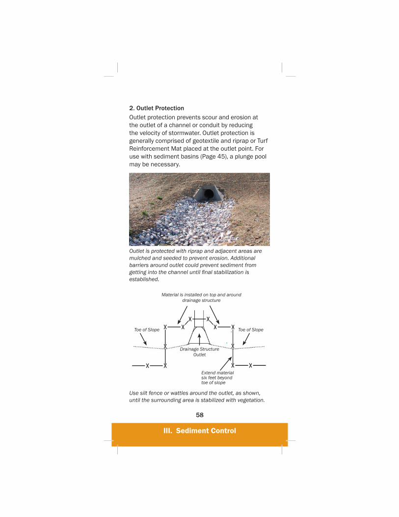
2. Outlet ProtectionOutlet protection prevents scour and erosion at the outlet of a channel or conduit by reducing the velocity of stormwater. Outlet protection is generally comprised of geotextile and riprap or Turf Reinforcement Mat placed at the outlet point. For use with sediment basins (Page 45), a plunge pool may be necessary.
Outlet is protected with riprap and adjacent areas are mulched and seeded to prevent erosion. Additional barriers around outlet could prevent sediment from getting into the channel until fi nal stabilization is established.
Material is installed on top and around drainage structure
Toe of Slope Toe of Slope
Drainage Structure Outlet
Extend material six feet beyond toe of slope
Use silt fence or wattles around the outlet, as shown, until the surrounding area is stabilized with vegetation.
III. Sediment Control
59
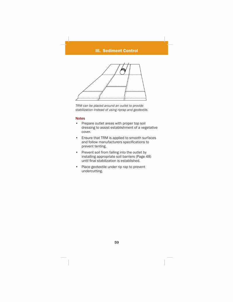
TRM can be placed around an outlet to provide stabilization instead of using riprap and geotextile.
Notes• Prepare outlet areas with proper top soil
dressing to assist establishment of a vegetative cover.
• Ensure that TRM is applied to smooth surfaces and follow manufacturers specifi cations to prevent tenting.
• Prevent soil from falling into the outlet by installing appropriate soil barriers (Page 48) until fi nal stabilization is established.
• Place geotextile under rip rap to prevent undercutting.
IV. Good Housekeeping
60
IV. Good Housekeeping
Contents A. Preservation of Vegetated Buffers . . . . . . .61
1. Environmentally Sensitive Areas . . . . . . 622. Construction Staging and Phasing . . . . 62
B. Perimeter Control . . . . . . . . . . . . . . . . . . . . .631. Construction Safety Barrier Fencing . . . 632. Berms and Diversions . . . . . . . . . . . . . . . 64
C. Dust Control . . . . . . . . . . . . . . . . . . . . . . . . . .66
D. Stabilized Construction Exits . . . . . . . . . . . .67
E. Solid Waste Management . . . . . . . . . . . . . .69
F. Stockpiles . . . . . . . . . . . . . . . . . . . . . . . . . . . .71
G. Secondary Containment . . . . . . . . . . . . . . . .73
H. Concrete Washout . . . . . . . . . . . . . . . . . . . . .75
I. Street Sweeping & Vacuuming . . . . . . . . . . .76

IV. Good Housekeeping
61
IV. Good Housekeeping
A. Preservation of Vegetated BuffersBy carefully delineating and controlling the areas not to be disturbed by grading or construction activities, the potential for soil erosion and stormwater pollution problems is reduced. Vegetated buffers provide erosion and sediment control, detention, fi ltration, and add aesthetic values to a site during and after construction. Preserved vegetation intercepts rainfall, promotes infi ltration, and processes higher quantities of stormwater runoff than newly planted areas that have to become established.
Use vegetated buffers to your advantage as natural erosion control. Add an extra layer of protection with perimeter controls before starting construction.
IV. Good Housekeeping
62
1. Environmentally Sensitive AreasSpecifi c precautions may be required to prevent impacts to environmentally sensitive areas. Vegetated buffers should be used to keep construction away from streams, lakes, wetlands, special habitats, historical properties, trees to be preserved and other special assets. Many of these assets are likely to be regulated by special permits or special provisions agreed to in the project planning phase. Vegetated buffers are an excellent method to comply with permit and contract requirements and protect these areas.
2. Construction Staging and PhasingContractors should preserve vegetated buffers as a temporary BMP during the construction project. Preserve areas that are already vegetated for as long as possible to provide an inexpensive sediment and erosion control BMP.
Notes• Mark off vegetated buffer areas before
construction begins using appropriate perimeter controls (Page 63).
• Limit disturbed areas to only those necessary for construction of the project.
• Supplement buffer areas for waterways and wetlands with construction barrier fence, silt fence and/or wattles.
• Educate equipment operators or use signs to warn vehicular traffi c to avoid preservation areas. Keep preservation areas clear of construction materials.
IV. Good Housekeeping
63
B. Perimeter Control Perimeter controls such as fences, berms and mulches are used to control sediment laden runoff from leaving a construction site and to divert upland clean stormwater from entering the site. They are also used to defi ne the construction site perimeter and environmentally sensitive areas. It is important that perimeter controls are in place before any earth-moving activities begin.
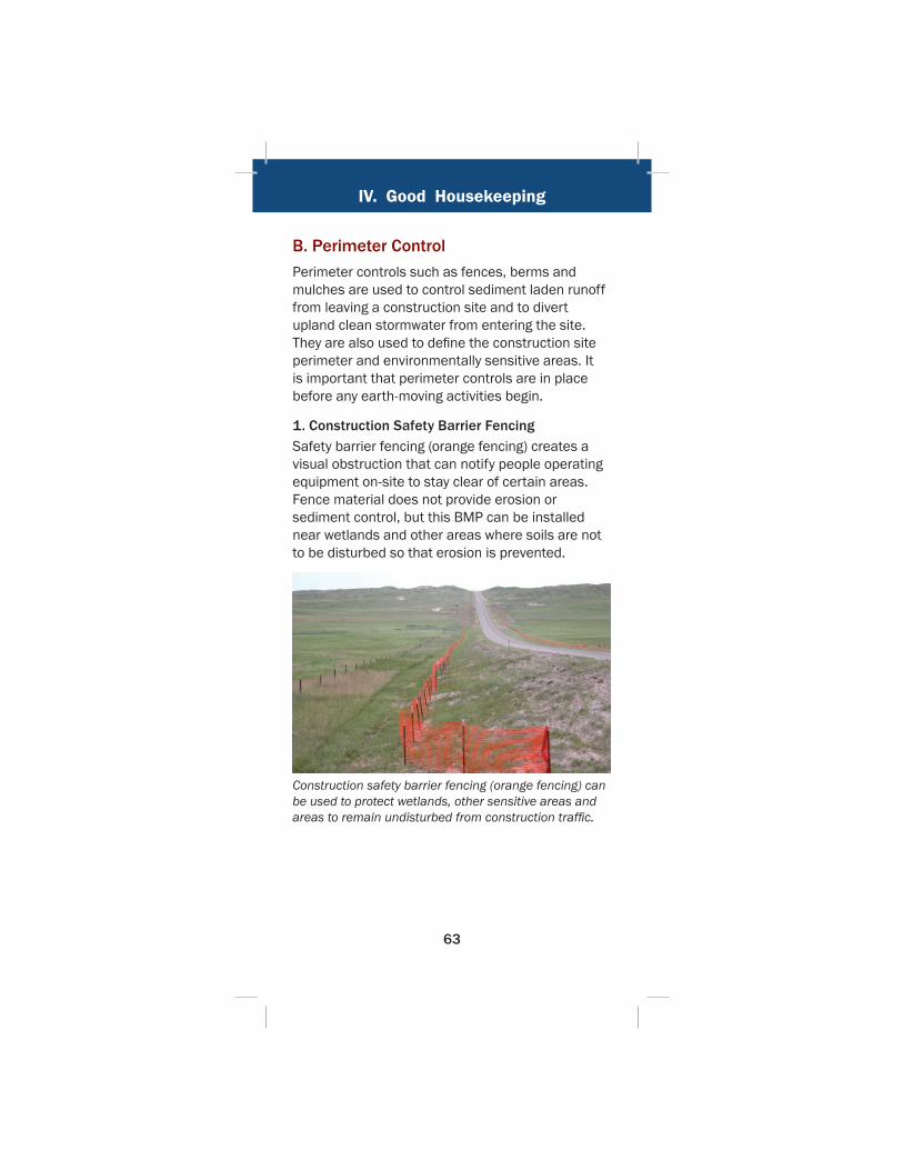
1. Construction Safety Barrier FencingSafety barrier fencing (orange fencing) creates a visual obstruction that can notify people operating equipment on-site to stay clear of certain areas. Fence material does not provide erosion or sediment control, but this BMP can be installed near wetlands and other areas where soils are not to be disturbed so that erosion is prevented.
Construction safety barrier fencing (orange fencing) can be used to protect wetlands, other sensitive areas and areas to remain undisturbed from construction traffi c.

IV. Good Housekeeping
64
2. Berms and DiversionsA mulch, compost or soil berm or diversion is a temporary ridge that slows and fi lters fl ow and diverts stormwater from an open area or slope. Diversions are designed to intercept and divert upland runoff around bare soil areas. Berms and ditches diverting upland runoff around construction sites reduce erosion and sedimentation problems.
Good example of a soil berm used for perimeter control.
If possible, divert stormwater around your site.
Berms and Diversions continued on next page.
IV. Good Housekeeping
65
Notes
• Seed soil berms and ditches after they are constructed.
• Repair and inspect perimeter controls often for breaches.
• Berm heights should not exceed a height of fi ve feet. The desirable top width is four feet and the side slopes should be 3:1 or fl atter.
• Berms should not be used in locations where they can be damaged by vehicle traffi c.
• Direct runoff down slopes in non-erosive manner and protect outlets to prevent washouts.
IV. Good Housekeeping
66
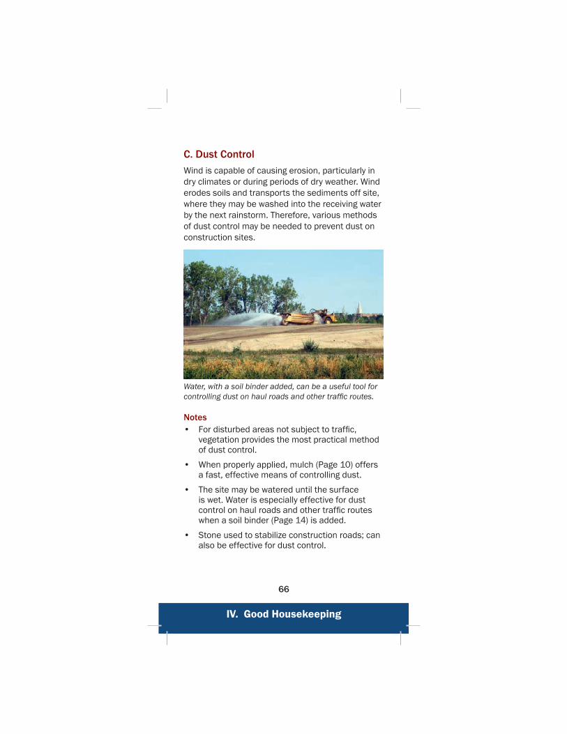
C. Dust ControlWind is capable of causing erosion, particularly in dry climates or during periods of dry weather. Wind erodes soils and transports the sediments off site, where they may be washed into the receiving water by the next rainstorm. Therefore, various methods of dust control may be needed to prevent dust on construction sites.
Water, with a soil binder added, can be a useful tool for controlling dust on haul roads and other traffi c routes.
Notes• For disturbed areas not subject to traffi c,
vegetation provides the most practical method of dust control.
• When properly applied, mulch (Page 10) offers a fast, effective means of controlling dust.
• The site may be watered until the surface is wet. Water is especially effective for dust control on haul roads and other traffi c routes when a soil binder (Page 14) is added.
• Stone used to stabilize construction roads; can also be effective for dust control.

IV. Good Housekeeping
67
D. Stabilized Construction ExitsWhen vehicles and equipment drive off of a construction site, mud and sediment can be tracked onto paved surfaces unless the exit area is stabilized. Stabilized exits made of crushed rock or other approved materials provide an area for vehicles to drive over before leaving the construction area. Driving over these areas will vibrate the vehicle, knocking the sediment loose from the tires. Exits should be installed in strategic locations to encourage operators to use them as much as possible. When a stabilized construction exit is specifi ed, geotextile is used to separate the stabilizing material from the soil below.
Install stabilized exits in strategic locations to encourage operators to use them as much as possible.

IV. Good Housekeeping
68
Good construction exit. When areas fi ll with sediment, more rock should be added to keep the exit effective.
Poor example of a construction exit. Vehicles are tracking sediment off-site.
Notes• Ensure material does not get tracked onto
nearby roads or travel routes. Clean roads throughout the day to maintain safety.
• Encourage all vehicles to use the stabilized construction exits.
• Replace and/or add material as needed to maintain the effectiveness of the BMP.
IV. Good Housekeeping
69
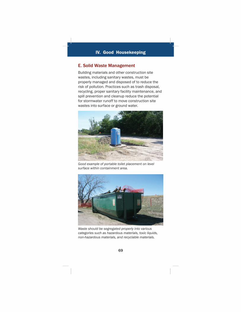
E. Solid Waste ManagementBuilding materials and other construction site wastes, including sanitary wastes, must be properly managed and disposed of to reduce the risk of pollution. Practices such as trash disposal, recycling, proper sanitary facility maintenance, and spill prevention and cleanup reduce the potential for stormwater runoff to move construction site wastes into surface or ground water.
Good example of portable toilet placement on level surface within containment area.
Waste should be segregated properly into various categories such as hazardous materials, toxic liquids, non-hazardous materials, and recyclable materials.

IV. Good Housekeeping
70
Notes• Designate trash and bulk waste collection
areas on-site. Keep them away from high traffi c areas, watercourses and other protected areas.
• Recycle materials whenever possible.
• Segregate and provide proper disposal options for hazardous material wastes.
• Clean up litter and debris from the construction site daily.
• Locate portable toilets away from drainage facilities, watercourses, and from traffi c circulation.
• Secure portable toilets to prevent overturning.
• Provide secondary containment around portable toilets.

IV. Good Housekeeping
71
F. StockpilesStockpiles of soil and other erodible materials must be managed so that stormwater does not wash pollutants into state waters including waterways and wetlands.
Poor example of stockpile management. Protect stockpiles with silt fence or other BMPs and seed if left undisturbed for more than 14 days.
Good installation of silt fence around stockpile. The fence is placed at least six feet from the toe of the slope to provide a catchment area and easy clean out. Stockpiles must be stabilized if left undisturbed for more than 14 days.

IV. Good Housekeeping
72
Notes
• Topsoil/embankment stockpiles should be sprayed with soil tackifi er, a hydraulically applied mulch or have mulch/mulch tackifi er applied to prevent wind erosion.
• Provide temporary stabilization where work on stockpiles is paused at least 14 days.
• The toe of erodible stockpiles must be protected with silt fence or other applicable BMPs.
• Do not place stockpiles in drainage ways or near state waters.

IV. Good Housekeeping
73
G. Secondary ContainmentAll building materials that have the potential to contaminate stormwater or groundwater must be placed in areas with secondary containment. Secondary containment prevents a spill from spreading across a site.
Good example of secondary containment. Be sure to replace the drain plug after clean water has been allowed to drain out.
Good use of a soil berm for secondary containment. Containment area must be large enough to capture a complete tank rupture.
IV. Good Housekeeping
74
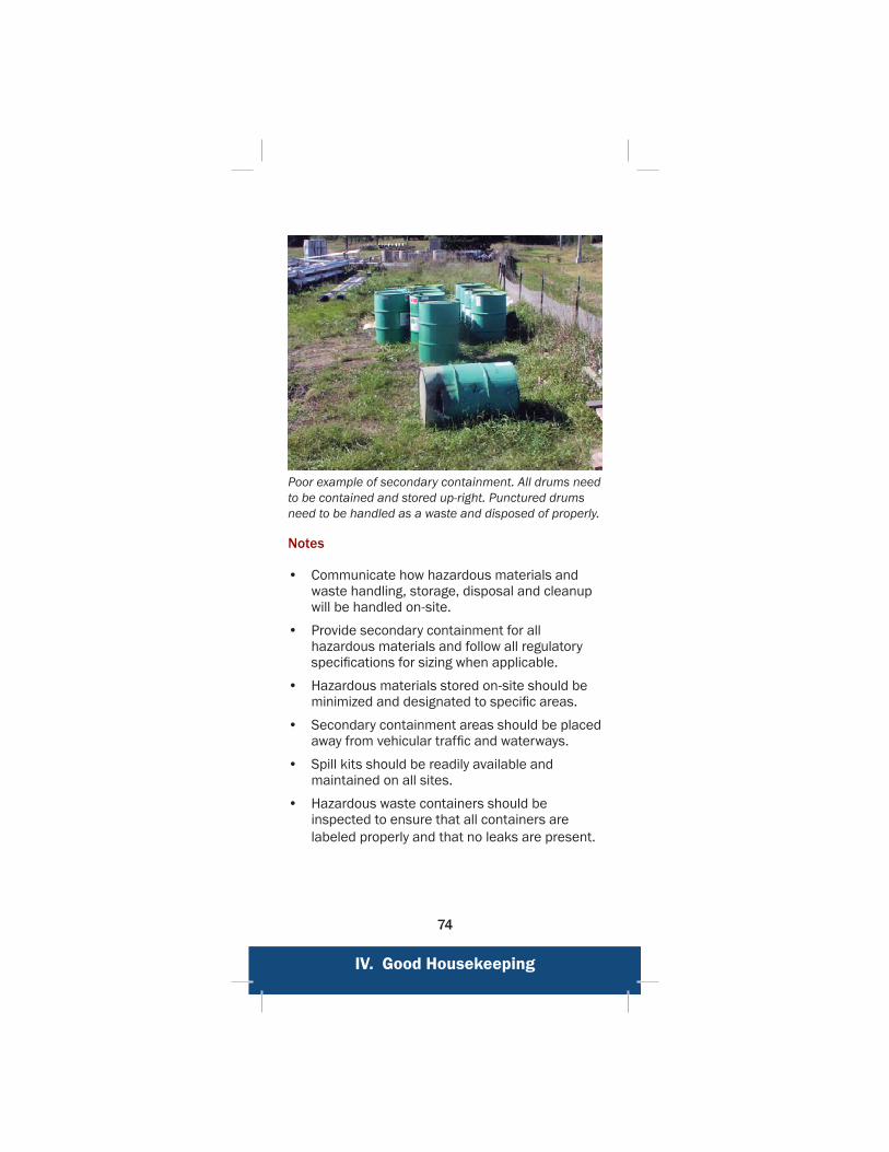
Poor example of secondary containment. All drums need to be contained and stored up-right. Punctured drums need to be handled as a waste and disposed of properly.
Notes
• Communicate how hazardous materials and waste handling, storage, disposal and cleanup will be handled on-site.
• Provide secondary containment for all hazardous materials and follow all regulatory specifi cations for sizing when applicable.
• Hazardous materials stored on-site should be minimized and designated to specifi c areas.
• Secondary containment areas should be placed away from vehicular traffi c and waterways.
• Spill kits should be readily available and maintained on all sites.
• Hazardous waste containers should be inspected to ensure that all containers are labeled properly and that no leaks are present.
IV. Good Housekeeping
75
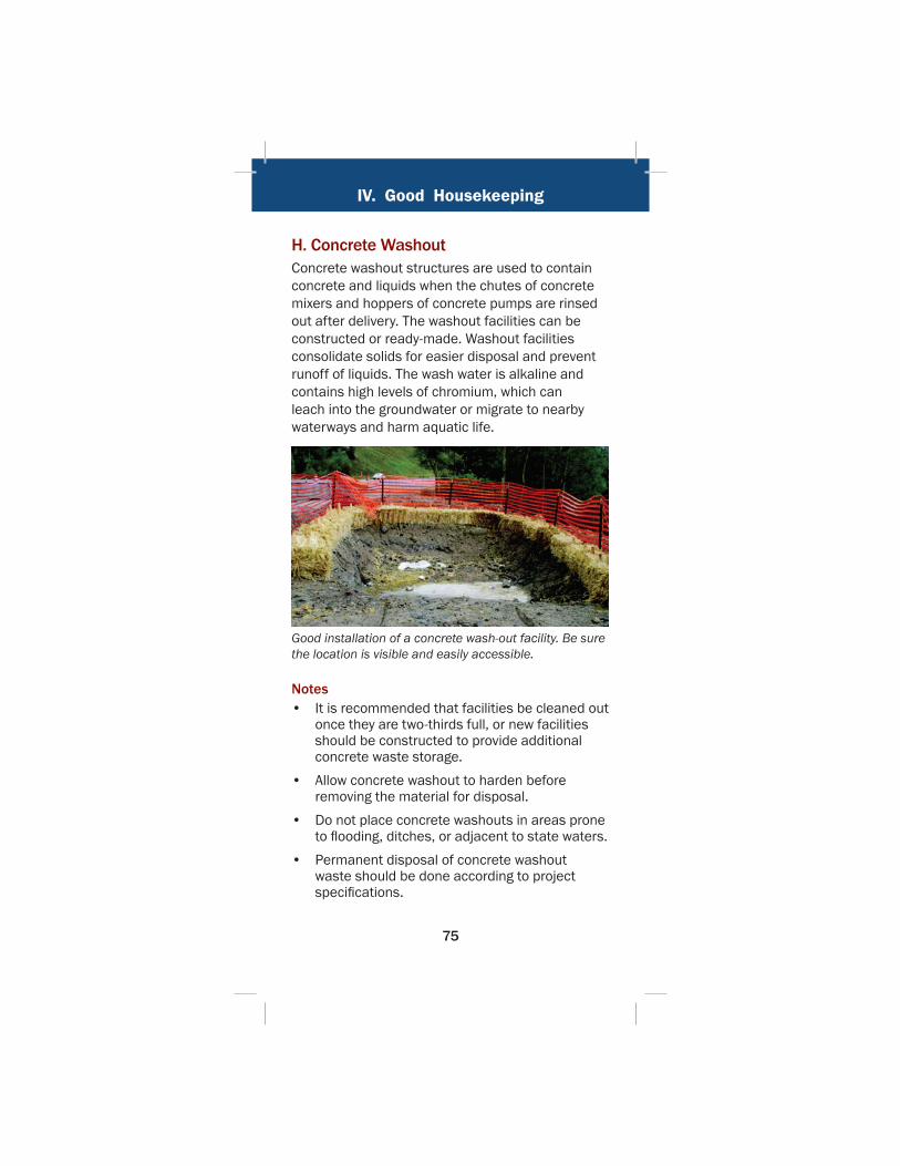
H. Concrete WashoutConcrete washout structures are used to contain concrete and liquids when the chutes of concrete mixers and hoppers of concrete pumps are rinsed out after delivery. The washout facilities can be constructed or ready-made. Washout facilities consolidate solids for easier disposal and prevent runoff of liquids. The wash water is alkaline and contains high levels of chromium, which can leach into the groundwater or migrate to nearby waterways and harm aquatic life.
Good installation of a concrete wash-out facility. Be sure the location is visible and easily accessible.
Notes• It is recommended that facilities be cleaned out
once they are two-thirds full, or new facilities should be constructed to provide additional concrete waste storage.
• Allow concrete washout to harden before removing the material for disposal.
• Do not place concrete washouts in areas prone to fl ooding, ditches, or adjacent to state waters.
• Permanent disposal of concrete washout waste should be done according to project specifi cations.
IV. Good Housekeeping
76
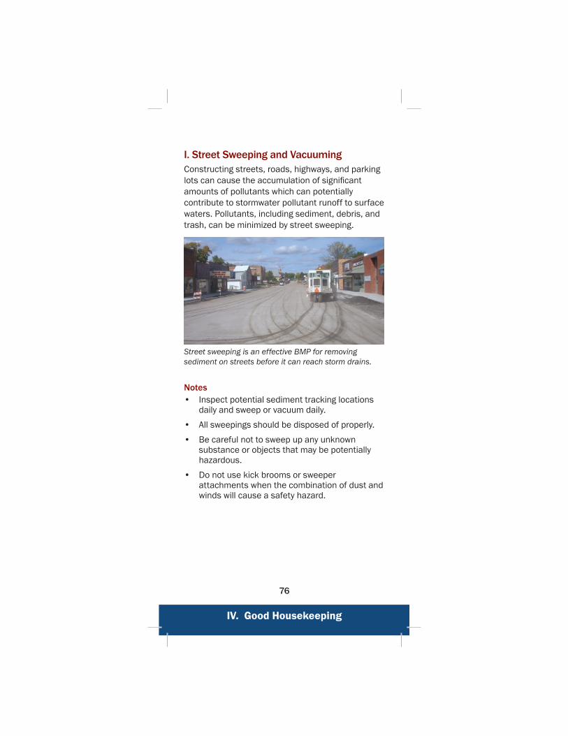
I. Street Sweeping and VacuumingConstructing streets, roads, highways, and parking lots can cause the accumulation of signifi cant amounts of pollutants which can potentially contribute to stormwater pollutant runoff to surface waters. Pollutants, including sediment, debris, and trash, can be minimized by street sweeping.
Street sweeping is an effective BMP for removing sediment on streets before it can reach storm drains.
Notes• Inspect potential sediment tracking locations
daily and sweep or vacuum daily.
• All sweepings should be disposed of properly.
• Be careful not to sweep up any unknown substance or objects that may be potentially hazardous.
• Do not use kick brooms or sweeper attachments when the combination of dust and winds will cause a safety hazard.
References and Acknowledgements
77
Special Thanks To:Nebraska Department of Environmental Quality for providing Clean Water Act, Section 319 grant funding to produce this manual.
Colorado Department of Transportation for providing BMP information and photos.
Minnesota Department of Transportation for providing BMP photos.
US Environmental Protection Agency for provid-ing BMP information and photos.
Erosion Control Technology Council for providing reference information.
For Additional References: www.transportation.nebraska.gov keyword search: stormwater
DisclaimerThis handbook was drafted in 2008 by a consultant for the Nebraska Department of Roads in an effort to provide a general overview of techniques and methods constituting best practices for handling of construction stormwater The information in this Guide is general guidance and does not supersede or replace any project plan, specifi cations, special provision, SWPPPs or other project specifi c commitments. The information in the handbook should not be considered to be legal advice. Please consult an attorney before taking any action concerning your specifi c rights, obligations or duties under local, state or federal law.

V. NDOR Specifi c Information
Nebraska Department of RoadsPlanning & Project Development
Roadside Stabilization Unit1500 Hwy 2
Lincoln, NE 68502
www.transportation.nebraska.gov