network architecture and protocols - capanina
TRANSCRIPT
FP6-IST-2003-506745 CAPANINA
Deliverable Number D27
Network architecture and protocols Specification of network architecture and protocols , including QoS,
interoperability issues, network management, routin g in mobile environment and the implications of all-optical backhaul networ k for the delivery of
broadband services from high altitude platforms
Document Number CAP-D27-WP25-BUTE-PUB-01
Contractual Date of Delivery to the CEC 1st Nov 2006
Actual Date of Delivery to the CEC 16th October 2006
Author(s): Dung Dinh Luong (BUTE), Mihael Mohorcic (JSI), Tien Van Do (BUTE), Roman Novak (JSI), Ales Svigelj (JSI), Matteo Berioli (DLR), Andrej Vilhar (JSI), Carolina Fortuna (JSI), Adam Glicser (BUTE), Nam Do Hoai (BUTE), Gergo Buchholcz (BUTE).
Participant(s) (partner short names): BUTE, JSI, DLR
Editor (Internal reviewer) Matteo Berioli (DLR), Anton Donner (DLR)
Workpackage: WP2.5
Estimated person months 49
Security (PUBlic, CONfidential, REStricted)
PUB
Nature REPORT
CEC Version 1.1
Total number of pages (including cover): 172
Abstract :
This deliverable specifies the network architecture and protocols, which are suitable for the provision of services and applications in CAPANINA operating scenarios. Based on the basic assumptions and the network architecture’s requirements, the specification work of the network architecture and protocols can be reduced to the identification of the main issues specific to HAP-based broadband access network and their detailed consideration. These issues include: (i) investigation of QoS implementation and service provisioning for the mobile access network, described in Chapter 3 focusing on effective packet scheduling and admission control applicable to HAP-based wireless networks, capable to guarantee QoS requirements; (ii) investigation of additional network elements and/or functionality required to implement load balancing, error detection and recovery solutions in multiple HAP constellations, carried out in Chapter 4; (iii) investigation of path optimization, home agent placement and multi-homing architectures in the context of network layer mobility support with the aim to improve the backhaul link utilization, addressed in Chapter 5; (iv) investigation of the impact of physical network topology to wavelength requirements in all-optical backhaul network based on HAPs and performance evaluation of different routing and wavelength assignment schemes, described in Chapter 6; and (v) identification, specification and categorization of HAP-networks specific management parameters, which are missing in the existing management standards, given in Chapter 7.
Keyword list: network architecture, HAP, QoS, routing, network management, mobility, load balancing, error detection and recovery, all-optical networks.

Network architecture and protocols CAP-D27-WP25-BUTE-PUB-P03
15th October 2006 FP6-IST-2003-506745-CAPANINA Page 2 of 172
DOCUMENT HISTORY
Date Revision Comment Author / Editor Affiliation
31/08/06 P01 First complete draft distributed within WP2.5 for comments and further contributions
D. D. Luong BUTE
04/09/06 P02 Structural changes related to Chapters 2 and 3
D. D. Luong BUTE
08/09/06 P03 Revision of abstract and Introduction, addition of executive summary and some missing subchapters, minor revisions of main chapters, addition of appendices
D. D. Luong BUTE
19/09/06 P04 Further revision to most parts and submission of final draft to internal reviewers
D. D. Luong BUTE
09/10/06 P05 Modifications following the internal review
D. D. Luong BUTE
13/10/06 01 Final version incorporating SB comments
M. Mohorčič, D. D. Luong
JSI, BUTE
Document Approval (CEC Deliverables only)
Date of approval
Revision Role of approver Approver Affiliation
09/10/06 01 Editor (Internal reviewer) M Berioli & A Donner DLR
16/10/06 01 For the Scientific Board David Grace UOY

Network architecture and protocols CAP-D27-WP25-BUTE-PUB-P03
15th October 2006 FP6-IST-2003-506745-CAPANINA Page 3 of 172
EXECUTIVE SUMMARY
This document forms a deliverable from the CAPANINA workpackage WP2.5 concerned with network architecture and protocols. The purpose of this document is the specification of the network architecture suitable to deliver candidate services and applications targeted in CAPANINA Deliverable D1. With the assumption that CAPANINA HAP networks will be IP-based, the existing IP-based standards can be used and therefore, instead of the whole specification of the network architecture, HAP-specific problems have been identified and solutions for these problems have been proposed.
The starting point of this work are the basic assumptions, detailed in Chapter 2, upon which we build the required network architecture, analyse existing protocols and propose necessary modifications to meet HAP-specific requirements. In particular, we summarise the intended use of HAP network, including a brief overview of business models and network scenarios, and present some alternative communication technologies suitable for various segments of the HAP network. These assumptions have important impact on the network architecture and implications for provision of QoS, routing, network management and other network layer functionalities addressed in this report, as we discuss in this chapter. The most important assumption is that the HAP network should be IP-based. In the light of basic assumptions, we review the requirements specified in CAPANINA Deliverable D13 and identify the essential problems to be addressed.
Chapter 3 considers the QoS implementation issues for CAPANINA HAP networks, looking at the link layer based on the IEEE 802.16-SC wireless access technology, at two IP-based end-to-end QoS architectures (IntServ and DiffServ), as well as at mapping between network layer’s QoS parameters and link layer’s QoS parameters. We support the use of hybrid QoS architecture comprising IntServ and DiffServ to exploit the advantages of both of these QoS architectures. The mapping between IntServ and DiffServ traffic classes have been already discussed in several studies, however, the implementation of IntServ and DiffServ in the HAP networks with the assumption of IEEE 802.16-SC as the wireless access technology emerges several problems that we address in this chapter. With the variable bit rate of the IEEE 802.16 wireless links using adaptive coding and modulation techniques, the effective packet scheduling and call admission control are open issues requiring adequate solutions. These two mechanisms are the main tools to implement QoS requirements of the network architecture. Effective packet scheduling and admission control are investigated, capable to guarantee QoS requirements while keeping the resource utilization as high as possible. Solutions are proposed specific for HAP-based wireless networks. Besides the packet scheduling and admission control, other state-of-the-art mechanisms such as Multi-protocol Label Switching (MPLS) and Type of Service (TOS) Routing, can be combined with DiffServ to support QoS efficiently, as we show with performance evaluation based on simulations.
In Chapter 4, the load balancing is considered as a mechanism to use network resources efficiently and avoid poor performance in heavily loaded situations. In particular, the network architecture implications of using multiple platforms with partially or completely overlaid coverage areas are investigated, focusing on required additional network elements/functionality to provide the capacity increase. Different load balancing policies are discussed for the basic utilisation of multiple HAPs supporting only outbound connections from the HAP network, as well as for the advanced utilisation of multiple HAPs supporting outbound and inbound connections. In addition to increased system capacity multiple HAP constellations can also be used to improve the resilience of the system, which is an important parameter in designing a wireless system. The communications between users and HAPs, between HAPs or between HAP and terrestrial gateway will be wireless. Additionally, the floating or flying nature of the platforms will increase the potential for transmission errors, similar as in mobile communications, only that here we deal also with the mobility of base stations and not only the end users. Fast error detection and recovery is thus one of the most important issues and is also discussed in Chapter 4. Particular focus is given to MPLS-based solutions for error detection and recovery, by investigating several MPLS scenarios and their performance.
In Chapter 5 the network layer protocols and algorithms for provision of mobility support are studied. In addition to end-node mobility, a concept of mobile routers is presented as an important future mobility scenario. HAP network is well suited to support mobile router on a vehicle, i.e. train, bus, ship or automobile. In particular, a scenario in which network connectivity is provided to the passengers on-board a train is considered. We designate this particular scenario as HAP-to-train scenario. Two-level
Network architecture and protocols CAP-D27-WP25-BUTE-PUB-P03
15th October 2006 FP6-IST-2003-506745-CAPANINA Page 4 of 172
mobility emerges. Several issues are raised when Mobile IP is used as macro-mobility protocol. The main problem is that mobility has an adverse influence on the effectiveness of routing, which is of great importance when multiple wireless links are involved; and in HAP networks user-to-HAP links, backhaul links and inter-platform links are all wireless. Issues such as path optimization, home agent placement and multi-homing architectures are studied in detail as these mechanisms have substantial influence on the backhaul link utilization. We discuss how propositions that have emerged recently in the Internet community fit with the HAP network architecture. Original solutions are proposed; some of them are general enough to be applied to other types of access networks.
The concept of optical transport network and its application to CAPANINA HAP networks are discussed in Chapter 6, based on the assumption that the use of free-space optics can be extended from inter-platform links also to the backhaul uplink/downlink between the HAP and the fixed ground station. This high-speed all-optical network concept would satisfy the particularly bandwidth-demanding requirements of the aggregate traffic load from/to several tens or hundreds of cells within the HAP coverage area. We address various technologies and concepts supporting such optical transport network (OTN) including the wavelength division multiplex (WDM) concept and the wavelength routing. We investigate the impact of physical network topology to the number of different required wavelengths to maintain all-optical paths between all nodes in the network, taking into account some basic regular topologies as well as representative general topologies. We also provide representative simulation results investigating the impact of physical network topologies, the effect of link failure and the performance of different routing and wavelength assignment schemes. In particular, we show that the performance of the routing algorithm is by far more important than the performance of the wavelength assignment algorithm. We also show, both analytically for regular topologies and numerically for representative generalised topologies, that for large networks double/multiple-hop routing is inevitable.
In Chapter 7 we show that increasing the management reliability is an important factor to be solved for the management of HAP networks. We analyse several network management solutions and select the suitable one for HAP networks. We identify several management parameters, specific to the HAP networks, which are still missing in the existing management standards, and we specify these parameters and categorize them into different groups.
The basic assumption taken in this study, i.e. that CAPANINA HAP network should be based on the IP standards, allowed the approach where different HAP-specific issues were identified and addressed within the dedicated personnel and time resources. The issues addressed in this report more in detail represent the subset of HAP-specific networking issues that are particularly relevant for the specific CAPANINA high-speed train operating scenario. In this scenario IEEE 802.16-SC standard has been selected for the wireless access technology bridging the mobile collective networks and the network of HAPs, and the second year trial confirmed the possibility to use free-space optics for the backhaul uplink and downlink between HAP and a fixed ground station in cloud-free conditions. The solutions for other identified HAP-specific issues requiring further investigation, however, are believed to be applicable to the CAPANINA operating scenario without major adaptations.

Network architecture and protocols CAP-D27-WP25-BUTE-PUB-P03
15th October 2006 FP6-IST-2003-506745-CAPANINA Page 5 of 172
TABLE OF CONTENTS
1 INTRODUCTION........................................................................................................... 18
2 BASIC ASSUMPTIONS AND REQUIREMENTS ................. ......................................... 20 2.1 Introduction ...............................................................................................................................20 2.2 Basic Assumptions....................................................................................................................21 2.2.1 Business Models ....................................................................................................................21
2.2.1.1 Internet Connection........................................................................................................................ 22 2.2.1.2 Internet Connection for Collective Mobile Networks....................................................................... 22 2.2.1.3 Broadcast Services ........................................................................................................................ 23
2.2.2 Network Scenarios .................................................................................................................23 2.2.2.1 Standalone Platform Scenarios...................................................................................................... 23
2.2.2.1.1 Standalone Platform Scenario without On-Board Processing................................................. 23 2.2.2.1.2 Standalone Platform Scenario with On-Board Processing...................................................... 24
2.2.2.2 Multiple Platform Scenario with Inter-Platform Links...................................................................... 25 2.2.3 Communication Technologies................................................................................................26
2.2.3.1 Access Segment ............................................................................................................................ 26 2.2.3.2 IP as the Network Layer Protocol................................................................................................... 27 2.2.3.3 MPLS ............................................................................................................................................. 28 2.2.3.4 All-optical Transport Network ......................................................................................................... 29
2.3 Network Architecture Requirements and the Impacts of Basic Assumptions...........................29 2.3.1 Service Requirements ............................................................................................................29 2.3.2 Technical Requirements.........................................................................................................30 2.3.3 HAP Specific Requirements ...................................................................................................31 2.3.4 Impacts of Basic Assumptions ...............................................................................................32
2.4 Summary...................................................................................................................................33
3 QOS CONSIDERATIONS............................................................................................. 34 3.1 Introduction ...............................................................................................................................34 3.2 Selected QoS Architecture for the CAPANINA HAP Networks and Implementation Solutions 34 3.2.1 Hybrid QoS Architecture.........................................................................................................35 3.2.2 Bandwidth Broker and Admission Control for DiffServ...........................................................35
3.3 APS: a Packet Scheduling Algorithm for High System Throughput on the Access Link ..........36 3.3.1 System Model.........................................................................................................................37 3.3.2 The Adaptive Profile Scheduling ............................................................................................38
3.3.2.1 Motivation and Contribution of APS ............................................................................................... 39 3.3.2.2 Adaptive Profile Scheduling ........................................................................................................... 39
3.3.3 Simulation Results..................................................................................................................42 3.3.4 Carrying QoS Traffic on the Wireless Access Downlink ........................................................45 3.3.5 Using APS for Access Uplink .................................................................................................45
3.4 Simulation Investigation for IEEE 802.16 Wireless Access Link’s QoS with a Measurement-Based Admission Control Algorithm .........................................................................................46
3.4.1 Admission Control Problem Related to Adaptive Profiles ......................................................46 3.4.2 Evaluation...............................................................................................................................47
3.5 Problems Related to Carrying Signalling Messages over the Wireless Access Link ...............49

Network architecture and protocols CAP-D27-WP25-BUTE-PUB-P03
15th October 2006 FP6-IST-2003-506745-CAPANINA Page 6 of 172
3.5.1 RSVP Messages over 802.16 Wireless Link..........................................................................49 3.5.2 RSVP Re-establishment.........................................................................................................51
3.6 Combining DiffServ, ToS Routing and MPLS to Support QoS .................................................53 3.6.1 DiffServ Approach ..................................................................................................................55 3.6.2 DiffServ over MPLS Approach ...............................................................................................55 3.6.3 ToS Routing Approach ...........................................................................................................56 3.6.4 ToS Routing over MPLS Approach ........................................................................................59 3.6.5 DiffServ and ToS Routing over MPLS Approach ...................................................................60 3.6.6 DiffServ over ToS Routing Approach .....................................................................................61 3.6.7 Simulations and Performance Evaluation ..............................................................................62
3.6.7.1 End-to-end Delay and Throughput Analysis .................................................................................. 63 3.6.7.2 Network Load Balancing ................................................................................................................ 65
3.7 Summary...................................................................................................................................66
4 LOAD BALANCING, ERROR DETECTION AND RECOVERY....... .............................. 67 4.1 Introduction ...............................................................................................................................67 4.2 Load Balancing .........................................................................................................................68 4.2.1 Basic Utilisation of Multiple HAPs...........................................................................................69 4.2.2 Advanced Utilization of Multiple HAPs ...................................................................................71
4.3 MPLS-based Solutions for Error Detection and Recovery........................................................72 4.3.1 MPLS-based Recovery over Packet Switched HAP Networks ..............................................73
4.3.1.1 Failure Discovery and Recovery .................................................................................................... 73 4.3.1.1.1 Failure Discovery..................................................................................................................... 74 4.3.1.1.2 Failure Recovery with 1+1 Protection...................................................................................... 75 4.3.1.1.3 Shared Mesh Restoration........................................................................................................ 75
4.3.2 GMPLS-based Recovery over Wavelength Switched HAP Networks....................................76 4.3.2.1 HAP-to-HAP Connection Recovery................................................................................................ 77
4.3.2.1.1 1+1 Dedicated Path Protection ............................................................................................... 77 4.3.2.1.2 Shared Mesh Path Restoration ............................................................................................... 77
4.3.2.2 Restoring Connections after a HAP-to-Ground Failure.................................................................. 78 4.3.3 Recovery with MPLS over GMPLS over Wavelength Switched HAP Networks ....................79
4.4 Summary...................................................................................................................................80
5 NETWORK LAYER MOBILITY SUPPORT..................... .............................................. 81 5.1 Introduction ...............................................................................................................................81 5.2 Network Architecture for Mobility Scenario ...............................................................................82 5.3 Hierarchical Approach to Mobility Support ................................................................................83 5.3.1 Access-Level Mobility .............................................................................................................83 5.3.2 Micro-Mobility .........................................................................................................................83 5.3.3 Macro-Mobility ........................................................................................................................85 5.3.4 Other Issues ...........................................................................................................................86
5.4 Routing to Mobile Nodes...........................................................................................................86 5.4.1 Mobile IP.................................................................................................................................86 5.4.2 Hierarchical MIP .....................................................................................................................86 5.4.3 Mobile Routers .......................................................................................................................87
5.5 Route Optimization ...................................................................................................................91 5.5.1 Backhaul Link Utilization.........................................................................................................91 5.5.2 Intra-domain Routing Problem ...............................................................................................91
Network architecture and protocols CAP-D27-WP25-BUTE-PUB-P03
15th October 2006 FP6-IST-2003-506745-CAPANINA Page 7 of 172
5.5.3 Proxy Mobility Anchor Points ..................................................................................................95 5.5.4 Performance Analysis ............................................................................................................98
5.5.4.1 Numerical Evaluation ..................................................................................................................... 98 5.5.4.2 Simulation Evaluation................................................................................................................... 102
5.5.5 Proxy Home Agents ............................................................................................................. 104 5.6 Placement of Home Agents ....................................................................................................105 5.6.1 Placement Dilemma ............................................................................................................. 105 5.6.2 Simulation Evaluation ........................................................................................................... 105
5.6.2.1 Simulation Tool ............................................................................................................................ 106 5.6.2.2 Results ......................................................................................................................................... 106
5.7 Multihoming Support ............................................................................................................... 111 5.7.1 Configuration Taxonomy ......................................................................................................112 5.7.2 Handling NLOS Conditions...................................................................................................113 5.7.3 Route Optimality...................................................................................................................113 5.7.4 Simulation Evaluation ........................................................................................................... 114
5.7.4.1 Methodology................................................................................................................................. 114 5.7.4.2 Configurations.............................................................................................................................. 115 5.7.4.3 Results ......................................................................................................................................... 115
5.7.5 Open Issues ......................................................................................................................... 119 5.8 Summary................................................................................................................................. 120
6 ALL-OPTICAL BACKHAUL HAP NETWORK ................... ......................................... 121 6.1 Introduction .............................................................................................................................121 6.2 IPL Physical Constraints ......................................................................................................... 122 6.3 Optical Transport Network ......................................................................................................123 6.3.1 WDM Routing....................................................................................................................... 123 6.3.2 Physical Topologies.............................................................................................................. 126
6.3.2.1 Full Mesh Topology...................................................................................................................... 126 6.3.2.2 Bus Topology ............................................................................................................................... 128
6.4 Routing and Wavelength Assignment..................................................................................... 130 6.4.1 Routing ................................................................................................................................. 130
6.4.1.1 Fixed Routing ............................................................................................................................... 130 6.4.1.2 Fixed Alternate Routing................................................................................................................ 131 6.4.1.3 Adaptive Routing.......................................................................................................................... 131 6.4.1.4 Fault Tolerant Routing.................................................................................................................. 131
6.4.2 Wavelength Assignment ......................................................................................................132 6.4.2.1 Random Assignment.................................................................................................................... 132 6.4.2.2 First Fit Assignment ..................................................................................................................... 132
6.5 Performance evaluation of all-optical backhaul HAP network ................................................133 6.5.1 The Impact of Physical Network Topologies ........................................................................ 133
6.5.1.1 7 HAPs / 7 GSs Topologies ......................................................................................................... 133 6.5.1.2 7 HAPs / 14 GSs Topologies ....................................................................................................... 135
6.5.2 The Effect of Link Failure .....................................................................................................137 6.5.3 Performance Evaluation of Routing and Wavelength Assignment Schemes ...................... 140
6.5.3.1 Performance of the Wavelength Assignment Algorithms............................................................. 143 6.5.3.2 Performance of the Routing Algorithms ....................................................................................... 143 6.5.3.3 Performance of the Routing and Wavelength Assignment Algorithms ........................................ 143 6.5.3.4 Utilization of network resources ................................................................................................... 143 6.5.3.5 Need for double hops?................................................................................................................. 147
Network architecture and protocols CAP-D27-WP25-BUTE-PUB-P03
15th October 2006 FP6-IST-2003-506745-CAPANINA Page 8 of 172
6.6 Summary................................................................................................................................. 148
7 NETWORK MANAGEMENT SOLUTIONS FOR HAP NETWORKS ...... ..................... 149 7.1 Introduction .............................................................................................................................149 7.2 HAP-Specific Considerations.................................................................................................. 149 7.2.1 HAP Flight Control Related Issues....................................................................................... 149 7.2.2 Characteristics of the Network Architecture ......................................................................... 149 7.2.3 Control and Monitor of Communication Devices on Board ..................................................149
7.3 Specification of the Network Management ............................................................................. 150 7.3.1 Multiple Links to Provide High Availability in Communications with HAPs ........................... 151 7.3.2 New MIBs for HAP Networks ...............................................................................................152
7.3.2.1 MIB for HAP Control and Operation ............................................................................................. 152 7.3.2.2 MIB for Antennas ......................................................................................................................... 153 7.3.2.3 MIB for HAP Constellation ........................................................................................................... 153 7.3.2.4 MIB for Handoff ............................................................................................................................ 153 7.3.2.5 MIB for Optical Physical and Link Layer for Inter-platform Communication and Backhaul Optical Link 153 7.3.2.6 MIB for Mobile IP.......................................................................................................................... 155 7.3.2.7 MIB for QoS ................................................................................................................................. 156
7.4 Summary................................................................................................................................. 157
8 SUMMARY AND CONCLUSIONS............................ .................................................. 158
9 REFERENCES............................................................................................................ 160
APPENDICES.................................................................................................................... 166 A. Data Fields of DSx (DSA/DSC) Messages ............................................................................. 166 B. Mapping between IntServ Traffic Classes and IEEE 802.16 LL QoS Classes ....................... 167 C. Mapping between DiffServ Traffic Classes and IEEE 802.16 LL QoS Classes...................... 168 D. Mapping between IntServ Traffic Classes and DiffServ Classes............................................ 169 E. Channel Model for Performance Evaluation of APS...............................................................170

Network architecture and protocols CAP-D27-WP25-BUTE-PUB-P03
15th October 2006 FP6-IST-2003-506745-CAPANINA Page 9 of 172
LIST OF FIGURES
Figure 1: General multi HAP network architecture. .. ........................................................................20 Figure 2: Standalone platform without on-board proc essing. ............................................ ............24 Figure 3: Standalone platform with on-board process ing. ............................................... ...............24 Figure 4: General network scenario under investigat ion................................................ .................26 Figure 5: Hybrid QoS architecture.................. ....................................................................................35 Figure 6: Processing and forwarding of RSVP message s with BB. ......................................... ......36 Figure 7: The state transition between the Markov c hain’s states. ..................................... ...........42 Figure 8: The average throughput of APS and Round R obin versus the minimal guaranteed
bandwidth.......................................... .................................................................................44 Figure 9: The Fairness index versus time. .......... ..............................................................................44 Figure 10. Packet scheduling at access wireless dow nlink. ............................................. ..............45 Figure 11: Histogram of used capacity (number of as signed slots), (a) for model 1-2 and (b) for
model 3-5. ......................................... ..................................................................................48 Figure 12: Mapping for RSVP messages into LL signal ling messages...................................... ....50 Figure 13: Re-establish the IntServ connection by s ending RSVP PATH and RESV again. ........52 Figure 14: Using RSVP proxy........................ ......................................................................................52 Figure 15: MPLS deployment over a HAP network...... .....................................................................54 Figure 16: Core node in DiffServ approach. ......... .............................................................................55 Figure 17: Core node in DiffServ-over-MPLS approach ...................................................................56 Figure 18: Core node in ToS-routing approach. ...... .........................................................................57 Figure 19: Link-Cost functions for the different tr affic classes in ToS routing approach............59 Figure 20: Core node in ToS-routing-over-MPLS appro ach. ............................................... ............60 Figure 21: Core node in DiffServ-ToS-routing-over-M PLS approach. ...................................... ......60 Figure 22: Core node in DiffServ over ToS routing a pproach. ........................................... .............61 Figure 23: Link cost functions for the different tr affic classes in the DiffServ over ToS routing
approach........................................... ..................................................................................62 Figure 24: End-to-end delay-throughput curves...... .........................................................................64 Figure 25: Percentage of network resources utilizat ion. ............................................... ..................65 Figure 26: Multi HAP Network architecture which inc ludes overlaid HAP coverage. ...................68 Figure 27: Traffic flows if only one HAP is utilize d...........................................................................69 Figure 28: HAP architecture for basic utilization o f multiple HAPs. ................................... ............70 Figure 29: HAP architecture for advanced utilizatio n of multiple HAPs................................. ........72 Figure 30: Failure domains. ........................ ........................................................................................72 Figure 31: MPLS domain. ............................ ........................................................................................73 Figure 32: MPLS recovery roles for the upstream con nection............................................ ............74 Figure 33: MPLS shared path restoration recovery pr ocedure. ........................................... ...........75 Figure 34: GMPLS over WDM HAP network topology..... .................................................................76 Figure 35: Shared Path Restoration recovery steps.. .......................................................................78 Figure 36: Non-gateway HAP failure. ................ .................................................................................79 Figure 37: Rerouted connections after a non-gateway HAP failure....................................... .........79 Figure 38: HAP network topology for routing protoco l investigation. ................................... ........82 Figure 39: Single-HAP vs. multiple-HAP micro-mobili ty area............................................ ..............84 Figure 40: Two-level MIP routing with CN in global network. ........................................... ..............88 Figure 41: Two-level MIP routing for HAP-to-HAP tra ffic. .............................................. ..................89 Figure 42: Two-level MIP routing after first-level route optimization (CN in global network). .....89
Network architecture and protocols CAP-D27-WP25-BUTE-PUB-P03
15th October 2006 FP6-IST-2003-506745-CAPANINA Page 10 of 172
Figure 43: Two-level MIP routing after first-level route optimization (CN in HAP network). ........90 Figure 44: HMIP-based route optimization. .......... .............................................................................91 Figure 45: HMIP-based route optimization in an HAP network. ........................................... ...........92 Figure 46: Unrealistic solution to the backhaul lin k issue............................................ ...................92 Figure 47: HMIP based route optimization control me ssages............................................. ............93 Figure 48: HMIP intra-domain data flow. ............ ...............................................................................94 Figure 49: Data packet formats..................... ......................................................................................94 Figure 50: PMAP control message flow............... ..............................................................................95 Figure 51: Sequences of control packet transmission s...................................................................96 Figure 52: PMAP intra-domain data flow. ............ ..............................................................................97 Figure 53: Sequence of optimized data packet transm ission. ............................................ ............97 Figure 54: PMAP-optimized route in an HAP network.. ....................................................................98 Figure 55: HMIP domain model ( L = 2, n = 3).....................................................................................99 Figure 56: Reduction of MRL vs. domain depth ( n = 4).................................................................. 100 Figure 57: Reduction of MRL vs. network scale ratio (n = 4)......................................................... 100 Figure 58: Reduction of MRL vs. node degree ( L = 3). ...................................................................101 Figure 59: Simulation network topology............. ............................................................................. 103 Figure 60: Performance of different TCP flows...... ......................................................................... 103 Figure 61: Dual interface architecture for MIP hand over during NLOS conditions. ...................106 Figure 62: Simulation network topology with CN in g lobal network. ..................................... ...... 107 Figure 63: TCP performance (CN in global network, b ackground traffic at 0%). ........................ 10 7 Figure 64: TCP performance (CN in global network, b ackground traffic at 94%). ...................... 108 Figure 65: TCP performance (CN in global network, b ackground traffic at 96%). ...................... 108 Figure 66: LOS percentage boundary. ................ .............................................................................109 Figure 67: Simulation network topology with CN in H AP network. ........................................ ...... 109 Figure 68: TCP performance (CN in HAP network, back ground traffic at 0%).............................1 10 Figure 69: TCP performance (CN in HAP network, back ground traffic at 96%)........................... 11 0 Figure 70: Simulation network topology............. ............................................................................. 114 Figure 71: Throughput (CN in global network). ...... ........................................................................ 116 Figure 72: Backhaul link utilization (CN in global network)........................................... ................ 116 Figure 73: Throughput (CN in HAP network).......... .........................................................................117 Figure 74: Backhaul link utilization (CN in HAP net work).............................................. ................117 Figure 75: Packet loss on HAP interface (LOS to NLO S transition)...................................... ........ 118 Figure 76: Packet loss on terrestrial network inter face (NLOS to LOS transition)...................... 118 Figure 77: Discarded packets on non-primary HA..... ..................................................................... 119 Figure 78: General all-optical transport network ar chitecture. ........................................ ............. 121 Figure 79: Block diagram of a HAP node with an opti cal cross-connect (single-hop approach).125 Figure 80: Block diagram of a HAP node in a multi-h op OTN employing WDM; (a) electronic
TDM, (b) statistical multiplexing used with the add /drop multiplexer. ...................... 125 Figure 81: Full mesh physical topology............. .............................................................................. 126 Figure 82: Bus physical topology................... ..................................................................................128 Figure 83: 7 HAPs / 7 GSs topologies. .............. ...............................................................................134 Figure 84: 7 HAPs / 14 GSs topologies. ............. .............................................................................. 136 Figure 85: Network topologies for the investigation of the effect of link failure. .................... .... 138 Figure 86: Evolution of blocking for 21-node topolo gy with failure on the link (3 ↔↔↔↔ 5). ............ 139 Figure 87: The European-wide topologies consisting of 35 HAPs. ........................................ ...... 140 Figure 88: Performance of the routing and wavelengt h assignment algorithms. ....................... 141

Network architecture and protocols CAP-D27-WP25-BUTE-PUB-P03
15th October 2006 FP6-IST-2003-506745-CAPANINA Page 11 of 172
Figure 89: Blocking for the EU-1 topology with 128 wavelengths per link. .............................. ... 146 Figure 90: Blocking for the EU-2 topology with 128 wavelengths per link. .............................. ... 146 Figure 91: Agents in HAP network devices. .......... .......................................................................... 151 Figure 92: Differentiated Services Code Point ...... ..........................................................................168 Figure 93: Rayleigh fading channel with K-state Mar kov model.......................................... .........171

Network architecture and protocols CAP-D27-WP25-BUTE-PUB-P03
15th October 2006 FP6-IST-2003-506745-CAPANINA Page 12 of 172
LIST OF TABLES
Table 1: QoS classes of IEEE 802.16 standard. ...... ..........................................................................27 Table 2: Channel conditions. ....................... .......................................................................................42 Table 3: SNR thresholds............................ ..........................................................................................43 Table 4: Parameters of burst profiles.............. ...................................................................................43 Table 5: Transition probabilities of the Markov cha in................................................. .....................43 Table 6: Parameter setting of simulation........... ................................................................................47 Table 7: Packet loss, link utilization and blocking probability. ...................................... .................49 Table 8: Mapping between RSVP TSPEC and DSx service flow .............................................. .......51 Table 9: Mapping between RSVP FLOWSPEC and DSx serv ice flow........................................... ..51 Table 10: Advantages and disadvantages of different load balancing mechanisms....................71 Table 11: Optimal HA placement in terms of throughp ut and backhaul link loads..................... 111 Table 12: HAP system scenarios (HAP altitude – IPL length) [81]. ...................................... ......... 123 Table 13: Wavelength requirements in the full mesh topology; N = [2,10] and k = [1,3]. ........... 128 Table 14: Wavelength requirements in the bus topolo gy; N = [2,10] and k = [1,3]. ..................... 130 Table 15: Network topology characteristics and wave length requirements for 7 HAPs / 7 GSs.135 Table 16: Network topology characteristics and wave length requirements for 7 HAPs / 14 GSs.137 Table 17: The effect of removing a link............ ................................................................................ 139 Table 18: Network topology characteristics of the E U-1 and EU-2 topologies............................ 140 Table 19: Performance of RWA algorithms on the EU-1 topology. ......................................... ...... 142 Table 20: Performance of RWA algorithms on the EU-2 topology. ......................................... ...... 142 Table 21: Resource utilization by RWA algorithms on the EU-1 topology................................. .. 144 Table 22: Resource utilization by RWA algorithms on the EU-2 topology................................. .. 145 Table 23: Minimum number of wavelengths required fo r a 35 HAPs / 35 GSs network to
guarantee zero blocking. ........................... .....................................................................147 Table 24: Relevant parameters of service flow param eter set. .......................................... ........... 166 Table 25: Error parameter set. ..................... ..................................................................................... 167 Table 26: Mapping rules for IntServ services....... ...........................................................................167 Table 27: Mapping IntServ services into IEEE 802.16 LL QoS classes. ................................... ....167 Table 28: Mapping rules for DiffServ services. ..... .......................................................................... 169

Network architecture and protocols CAP-D27-WP25-BUTE-PUB-P03
15th October 2006 FP6-IST-2003-506745-CAPANINA Page 13 of 172
LIST OF ACRONYMS
AAA Authentication, Authorization and Accounting
ADM Add-Drop Multiplexer
ADSL Asymmetrical Digital Subscriber Line
AF Assured Forward
AN Anchor Node
AR Adaptive Routing
AR Access Router
ARQ Automatic Repeat reQuest
ATM Asynchronous Transfer Mode
ATN Aeronautical Telecommunication Network
APS Adaptive Burst profile Scheduling
BB Bandwidth Broker
BE Best Effort Service
BER Bit Error Rate
BGP Border Gateway Protocol
BU Binding Update
CAC Call Admission Control
CBR Constraint Based Routing
CID Connection Identification
CLS Controlled Load Service
CMIP Common Management Information Protocol
CMOT CMIP Over TCP/IP
CN Correspondent Node
CoA Care-of Address
CPS Common Part Sublayer
COTS Commercial Off-The-Shelf
CPE/TE Customer Premise Equipment / Terminal Equipment
CR-LDP Constraint-based Routing Label Distribution Protocol
CS Convergence Sublayer
DiffServ Differentiated Services
DHCP Dynamic Host Configuration Protocol

Network architecture and protocols CAP-D27-WP25-BUTE-PUB-P03
15th October 2006 FP6-IST-2003-506745-CAPANINA Page 14 of 172
DIUC Downlink Interval Usage Code
DL Down Link
DRCL Distributed Relative Capacity Loss
DSA Dynamic Service Addition
DSC Dynamic Service Change
DSCP DiffServ Code Point
EDFA Erbium Doped Fiber Amplifier
EF Expedited Forward
E-LSP EXP-Inferred-PSC LSP
ER Edge Router
FA Foreign Agent
FEC Forwarding Equivalence Class
FF First Fit (assignment)
FIFO First-In First-Out
FIS Fault Indication Signal
FR Fixed Routing
FTP File Transfer Protocol
GGSN Gateway GPRS Support Node
GMPLS Generalized Multi-Protocol Label Switching
GN Global Network
GS Ground Station
GW Gateway
HA Home Agent
HAP High Altitude Platform
HAT HAP Access Terminal
HMIP Hierarchical Mobile IP
HoA Home Address
ICMP Internet Control Message Protocol
IEEE Institute of Electrical and Electronic Engineers
IETF Internet Engineering Task Force
IGP Interior Gateway Protocol
IntServ Integrated Services

Network architecture and protocols CAP-D27-WP25-BUTE-PUB-P03
15th October 2006 FP6-IST-2003-506745-CAPANINA Page 15 of 172
I/O Input/Output (module)
IP Internet Protocol
IPv4 IP version 4
IPL Inter-Platform Link
ISP Internet Service Provider
ITU-T International Telecommunications Union - Telecommunications
LAN Local Area Network
LCoA On Link Care-off Address
LD Link Degraded
LER Label Edge Router
LF Link Failure
L-LSP Label-Only-Inferred-PSC LSP
LOS Light Of Sight
LSP Label Switching Path
LSR Label Switching Router
MAC Media Access Control
MAP Mobile Anchor Point
MIB Management Information Base
MIP Mobile IP
MIPv4 MIP version 4
MIPv6 MIP version 6
MN Mobile Node
MPLS Multi-Protocol Label Switching
MR Mobile Router
NEMO Network Mobility Working Group
NLOS Non Light-Of-Sight
nrtPS Non-Real-Time Polling Service.
OCX Optical Cross Connect
OD Origin-Destination (pair)
OE Optical to Electronic (conversion)
OEO Optic-to-Electronic-Optic (conversion)
ORC Optimized Route Cache Management Protocol
Network architecture and protocols CAP-D27-WP25-BUTE-PUB-P03
15th October 2006 FP6-IST-2003-506745-CAPANINA Page 16 of 172
OSS Operational Support System
OTN Optical Transport Network
PAT Pointing, Acquisition and Tracking
PD Path Degraded
PF Path Failure
PHA Proxy Home Agent
PHB Per-Hop Behaviour
PMAP Proxy Mobility Anchor Point
PML Path Merge LSR
PMP Point-To-Multipoint
POR Point Of Repair
PSL Path Switch LSR
R Random (assignment)
RADIUS Remote Authentication Dial In User Service
RCoA Regional Care-off Address
RF Radio Frequency
rtPS Real-Time Polling Service.
RSVP Resource Reservation Protocol
RSVP-TE Resource reSerVation Protocol - Traffic Engineering extension
RWA Routing and Wavelength Assignment
SC Single Carrier
SLA Service Level Agreement
SNMP Simple Network Management Protocol
SNR Signal-to-Noise Ratio
SME Small and Medium size Enterprise
SOHO Small Office, Home Office
SS Subscriber Station
TACACS Terminal Access Controller Access-Control System
TCP Transmission Control Protocol
TDM Time Division Multiplexing
TMN Telecommunications Management Network
ToS Type of Service

Network architecture and protocols CAP-D27-WP25-BUTE-PUB-P03
15th October 2006 FP6-IST-2003-506745-CAPANINA Page 17 of 172
TTL Time-To-Live
QoS Quality of Service
UGS Unsolicited Grant Service
UIUC Uplink Interval Usage Code
UL Up Link
UMTS Universal Mobile Telecommunications System
VOD Video On Demand
VoIP Voice Over IP
VPN Virtual Private Network
WDM Wavelength Division Multiplexing
W-MAN Wireless Metropolitan Area Network
WRR Weighted Round Robin

Network architecture and protocols CAP-D27-WP25-BUTE-PUB-P03
15th October 2006 FP6-IST-2003-506745-CAPANINA Page 18 of 172
1 Introduction
In order to efficiently provide broadband services to customer premises and fast moving vehicles scalable and manageable network architecture needs to be defined, possibly based on an all-IP network concept supporting IP protocol. For such network architecture the most suitable protocol stack needs to be defined, capable of (i) mapping end-user QoS requirements on network and lower layer protocols, (ii) efficient and reliable routing in the mobile environment involving trains and platforms, and (iii) implementing methods and concepts to optimise the link utilization and improve the network performance.
The purpose of the present document is the specification of suitable network architecture for CAPANINA High Altitude Platforms (HAP) networks. Network architecture hereby means the overall structure including all elements, functionalities, mechanisms, protocols necessary to deliver the predefined sets of services and applications defined in CAPANINA Deliverable D1. Different types of targeted applications and services, as well as the large set of requirements for a HAP networks as a wireless networks providing mobility and using floating or flying base stations, make the network architecture become rich in technical features. Therefore, the specification of the network architecture becomes very demanding and challenging work and an important part of CAPANINA project’s contributions.
In order to specify a suitable network architecture, we first have to determine the required features and functionalities as well as basic assumptions of the CAPANINA HAP network. CAPANINA Deliverable D13 has defined a comprehensive set of requirements regarding the protocol stack, forwarding & routing protocols, QoS solutions, network management solutions, operating system support, etc. This complex system of requirements makes the specification of the network architecture extremely comprehensive and demanding task, which can be significantly relaxed by a good selection of applicable basic assumptions. In this work they include assumptions about business models, networking scenarios and communication technologies suitable for various segments of the HAP network. One important assumption is that IEEE 802.16 Single Carrier is the wireless access technology standard for CAPANINA’s HAP networks. The other important assumption is that we consider IP as the network layer protocol. With the latter assumption, the re-use of architecture and protocol (quasi-)standards and proposals is strongly advisable for two reasons: firstly it facilitates seamless interoperability with existing networks and secondly it minimizes superfluous work that would lead to reproduction of already existing solutions.
With the assumption of using IP, the set of requirements for the network architecture reduces to a set of problems which are mostly HAP-specific. Even more, in this work we identify and investigate more in detail those problems that are predominantly CAPANINA scenario specific, in particular:
• How to guarantee the QoS in HAP network with the chosen wireless access technology? (addressed in Chapter 3)
• How to use load balancing in multiple HAP networks, what are its implications to the network architecture and functionality of network elements, and how to detect network errors and recover from errors? (addressed in Chapter 4)
• How to address the mobility problems in HAP networks with mobile end-users, routers and base stations? (addressed in Chapter 5)
• What are the technologies and concepts necessary for supporting all-optical backbone networks and how these concepts affect the network topology and architecture? (addressed in Chapter 6)
• How to manage the HAP networks efficiently and resiliently? (addressed in Chapter 7)
The main frame of the study has been defined based on the basic assumptions for the HAP network architecture and on the network architecture requirements and the impacts of basic assumptions in Chapter 2.

Network architecture and protocols CAP-D27-WP25-BUTE-PUB-P03
15th October 2006 FP6-IST-2003-506745-CAPANINA Page 19 of 172
We focused on the problems related to QoS at the link layer in Chapter 3, especially on packet scheduling, measurement-based call admission control and QoS parameter mapping between the link layer based on IEEE 802.16-SC wireless access standard and networking layer considering a hybrid QoS architecture comprising of IntServ and DiffServ.
In Chapter 4, load balancing, error detection and recovery solutions are investigated from the perspective of additional network elements and/or functionality required in the network comprised of multiple interconnected HAP platforms.
In Chapter 5 we studied the network layer protocols and algorithms for the provision of mobility support, focusing on path optimization, home agent placement and multi-homing architectures, proposing some original solutions, which are general enough to be applied also to other types of access networks.
Chapter 6 addresses the concept of optical transport network and its application to CAPANINA HAP networks, focusing on the investigation of the impact of physical network topology to wavelength requirements and on the performance evaluation of different routing and wavelength assignment schemes.
In Chapter 7 we analyse several network management solutions and select the suitable one for HAP networks. We identify HAP-networks specific management parameters that are not addressed in the existing management standards and provide their specification.
Finally, in Chapter 8 we provide the overall summary of the work carried out in workpackage WP2.5 and draw some conclusions.

Network architecture and protocols CAP-D27-WP25-BUTE-PUB-P03
15th October 2006 FP6-IST-2003-506745-CAPANINA Page 20 of 172
2 Basic Assumptions and Requirements
2.1 Introduction
In this chapter, the background information is given on the intended use of HAP network from the perspective of the CAPANINA project, including a brief overview of business models and network scenarios. Some alternative communication technologies suitable for various segments of the HAP network are briefly presented, together forming basic assumptions for the investigated HAP network architecture. These assumptions have a profound impact on the analysis of network architectures and, in the first place, the implications for provision of QoS, routing, network management and other network layer functionalities. General network architectures and requirements for HAP system, representing a starting point for the studies reported in this document, were proposed and discussed in [19]. General reference network architecture for providing services to fixed users and fast trains (or other means of transport), equipped with collective terminal interfacing between the on-board LAN and the HAP, is depicted in Figure 1. Such network can consist of multiple HAPs, which are connected via backhaul link to gateway (GW) and further to the backbone network. HAPs can be further interconnected with inter-platform links (IPLs), making the HAP network architecture more flexible by means of number of gateways and backbone infrastructure. Users will typically not access directly to the HAP but connect via fixed or wireless LANs to HAP Access Termination (HAT), which can be either fixed (i.e. mounted on the building) or mobile (i.e. mounted on the vehicle, such as fast train in the particular case of CAPANINA).
backhaul link user link
Figure 1: General multi HAP network architecture.
CAPANINA D13 deliverable [19] describes the general requirements for the network architecture. In the following a brief but essential summary of requirements is presented in order to support better understanding of objectives of this deliverable and to provide the baseline for the analysis and comparison of different alternative solutions of the network architecture for HAP networks. The

Network architecture and protocols CAP-D27-WP25-BUTE-PUB-P03
15th October 2006 FP6-IST-2003-506745-CAPANINA Page 21 of 172
requirements are categorised according to service aspects, technical aspects and HAP-specific aspects.
• Service aspects
o Service provision for private subscribers and "business" subscribers
o Service requirements and QoS
o Point-to-point, point-to-multipoint, broadcast
• Technical aspects
o Communication technology (layer 1, 2 and 3, and equipment)
o Network topology
o Authentication and authorization solution
o Routing
o Network management
o Cooperation with the existing networks
o The use of COTS equipments, e.g. when IP or MPLS routers are used
• HAP-specific aspects:
o Equipment size and weight
o Energy consumption
Basic assumptions, especially the assumption that CAPANINA HAP networks are IP-based, have important impacts on the requirement system. More precisely, IP and the existing IP-based standards reduce the requirements for the network architecture. In the following, we will discuss about the impacts of basic assumptions on each requirement aspect.
2.2 Basic Assumptions
2.2.1 Business Models
To define a network architecture which can flexibly provide the candidate services and applications listed in CAPANINA Deliverable D1, business models should be considered in terms of architecture of the service, business actors involved and their roles, information flows in user, control and management plane.
We have following general business actors, which are described in CAPANINA Deliverable D1:
• HAP Network Operator
• Other Network Operator
• Service Provider
• Subscriber
• User
The HAP Network Operator is interested in making as much profit as possible. To do this, their network architecture has to be competitive in order to satisfy the customers’ demands: besides
Network architecture and protocols CAP-D27-WP25-BUTE-PUB-P03
15th October 2006 FP6-IST-2003-506745-CAPANINA Page 22 of 172
providing high bandwidth, necessary features such as QoS mechanisms and multicast should be implemented in the HAP networks. Recently, the network operators tend to wholesale services, e.g. ADSL operators wholesale ADSL connections, to the service providers who maintain direct relationship with subscribers. By leaving the customer care to service provider partners, partly or entirely, the network operators can focus on developing advanced infrastructure by which new services can be easily developed and activated. However, co-operation support between the HAP Network Operator and the Service Provider is an emerging important factor in network architecture design.
Candidate CAPANINA services and applications work under the following business models:
• Internet connection
• Internet Connection for Users on High-Speed Vehicles
• Broadcast services
2.2.1.1 Internet Connection
The Service Provider (Internet Service Provider in this case) buys services from the HAP Network Operator and possibly other network operators to provide Internet connectivity for subscribers. In the service contract, the Subscriber and Service Provider agree on the billing method. The Subscriber pays the Service Provider fix monthly price or according to the used amount of traffic or a combination of fix monthly price and a variable traffic price.
The antenna and CPE/TE (Customer Premise Equipment / Terminal Equipment) can be provided by the Service Provider or can be bought by the users on the market. In the later case, the user, control and management interfaces between the CPE/TE and HAP network must be open to the CPE/TE manufacturers.
The Subscriber can choose suitable Internet connection service from several options with regard to guarantee of service quality such as minimum upload and download bandwidth, loss rate, delay, jitter, etc.
Important operations related to the Internet connection service are service activation, the authentication of the Subscriber, fault performance, usage monitoring, billing mediation and billing. In order to perform these operations, the cooperation between the Network Operators and the Service Provider is required.
There are two groups of solutions providing cooperation between Network Operators and the Service Provider. The first group to minimize the necessary cooperation between the Network Operators and the Service Provider is to direct all information from the users to the Service Provider which perform as many operations as possible (user authentication, IP address distribution, usage monitoring, billing mediation and billing). In these solutions, the network operator must provide a virtual connection between the users and the Service Provider and do not care what kind of data transferred in the connection.
The other group of solutions leaves the main part of operations to the Network Operator and performs only customer service and billing. The data coming from the users do not need to be directed to the Service Provider and therefore, this solution enhances the flexibility in using network resources.
2.2.1.2 Internet Connection for Collective Mobile N etworks
The Service Provider in the case of Internet access on high-speed vehicles buys an Internet connection supporting mobility and roaming from the HAP network operator or another Internet Service Provider and provides Internet connectivity for travellers by installing a local Ethernet or Wi-Fi onboard. Currently, the well-known business model for this kind of service is the prepaid model applied for the Wi-Fi hotspot services. Prepaid subscribers can connect to the Internet only after successfully being identified by web-based authentication interface using valid username and password. The billing is based on connection time interval or amount of used traffic. The fee of Internet access can be included in the ticket fee. In that case, the authentication is not necessary.
Network architecture and protocols CAP-D27-WP25-BUTE-PUB-P03
15th October 2006 FP6-IST-2003-506745-CAPANINA Page 23 of 172
2.2.1.3 Broadcast Services
Examples of broadcast services are digital TV and digital radio. Broadcasting via HAP broadband delivery could serve the rural area beyond the reach of cable TV. Since the Service Provider has to pay the Network Operator for the network usage, it is interested in minimizing the network resource usage while maintaining adequate quality level of media data. The broadcast service may be offered in different packages with different combinations of TV and radio channels. Broadcast channels can be encoded in order to avoid unauthorized access. A good key management is necessary. The decoding keys are replaced by new keys after a time interval. The subscribers, who did not perform the payment in time, do not receive the new keys for the service. The key sending should be done automatically to the set-top box which performs the decoding as well. The subscriber does not have to worry about the key exchange.
2.2.2 Network Scenarios
Network scenarios to be explored and analyzed need to be defined. We first identify possible alternatives and variations in system components. Then we compose the most probable scenarios.
From the system architecture perspective HAPs can be used as standalone platforms, providing broadband wireless access for single-user (mobile or fixed) or collective terminals (mobile or fixed) in the coverage area to the central ground station (GS). Furthermore, they can be interconnected via terrestrial links between gateways or via inter-platform links to form a network of HAPs.
Such a telecommunication system can be deployed as a stand-alone network, which applies to the case where the platform is used in a remote area, where no terrestrial network exists and there is also no connectivity to satellites. To fully exploit HAPs capabilities, a network of HAPs has to be connected to external networks via gateways providing suitable internetworking functionality. Ground terminals communicate with platforms via user links, while GSs, hosting gateways to external networks and different servers, are connected to platforms via backhaul links, together forming an up/down link segment.
Another classification of HAPs can be done according to the location of switching equipment. In the case that there are no switching equipment on-board HAP (transparent payload), all the switching is done in GSs. While transparent payload enables the platform payload complexity, weight and power consumption to be significantly reduced, the backhaul requirements are more demanding and traffic from/to different cells needs to be efficiently aggregated / split on the platform.
Platforms with on-board switching (switching payload) capabilities provide some gain in terms of QoS parameters (mainly delay) to communicating parties within the same platform coverage area and potentially reduce the backhaul traffic. Furthermore, in order to deploy the network of platforms, which are connected by inter-platform links, the use of switching payload is necessary.
Topology design phase depends heavily on types of services, which are required in the system, and also on the desired coverage area of the system. In order to increase the system capacity, the coverage area of each platform is further divided into cells using multi-beam antennas. The coverage area depends on the number and configuration of HAPs and on the elevation angle at which the communicating terminal sees the platform.
Different network architectures can be deployed by different possible interconnections. In general, we can define three network scenarios, which are described more in detail in the following subsections:
2.2.2.1 Standalone Platform Scenarios
2.2.2.1.1 Standalone Platform Scenario without On-Board Processing
In a standalone platform scenario the system coverage is limited to the cellular coverage of a single platform, enabling only communication between terminals within the coverage area, or with terminals in other networks using a gateway located in the ground station. In this scenario a HAP with transparent payload is used. The backhaul links are heavily loaded, as all the user traffic passes through them to GS. In Figure 2 if the terminal A wants to send data to terminal B, the data has to be transferred to GS (1a, 1b) and the GS send it back to the terminal B (2a, 2b).

Network architecture and protocols CAP-D27-WP25-BUTE-PUB-P03
15th October 2006 FP6-IST-2003-506745-CAPANINA Page 24 of 172
Figure 2: Standalone platform without on-board proc essing.
In the simplest scenario without any on board processing (Figure 2) the HAP has the role of a transparent transponder. It relays all signals from/to the subscriber stations to/from the gateway on the ground. In this case, even modulation/demodulation and coding/decoding is not necessary. With this scenario, all network architecture functionalities can be placed on the ground. Note that, in the case of transparent payload, even the traffic between two users within the same coverage is passing through the GS.
2.2.2.1.2 Standalone Platform Scenario with On-Board Processing
Figure 3: Standalone platform with on-board process ing.
In the case of standalone platform scenario with on-board processing modulation/demodulation, coding/decoding and switching (routing) are implemented on board. If a subscriber terminal sends data to another one belonging to the same coverage of the HAP, the packets will be switched (routed) to the receiver directly without communication with the gateway (in Figure 3 the data transfer 1 and 2) on the ground as in the first scenario.

Network architecture and protocols CAP-D27-WP25-BUTE-PUB-P03
15th October 2006 FP6-IST-2003-506745-CAPANINA Page 25 of 172
2.2.2.2 Multiple Platform Scenario with Inter-Platf orm Links
The scenario with platform interconnection via inter-platform links (IPLs) provides extended system coverage with significantly reduced terrestrial infrastructure. To support communication between adjacent platforms without any ground network elements each HAP payload includes a switching device and one or more inter-platform link terminals. Depending on the link budget analysis we can choose between optical and radio frequency terminals. In this scenario GSs are used mainly as gateways to other public and/or private networks, while providing also a backup interconnection between platforms in the case of IPL failure. Implementation of IPLs significantly reduces requirements for terrestrial and user/backhaul segments, provides high flexibility of system coverage, and supports system operation independent of terrestrial network. On the other hand, IPL terminals represent additional weight and power consumption on the platform and require steerable IPL antenna to maintain permanent connection.
An alternative scenario with satellite links can be used to integrate the HAP system into other non-local terrestrial or satellite networks. It is mainly targeted for the use in areas with deficient or non-existing terrestrial infrastructure, typically rural and remote areas. In addition to providing connection of the platform to other public or private networks via satellite, platform to satellite links could also be used as a backup solution in the case when the connection with the rest of the network via IPL or GS is disabled due to a failure (e.g. natural disaster) or extreme rain fading on ground to HAP segment. The main drawback of satellite links is a need to use heavier terminals with higher power consumption in comparison to IPLs, due to the longer communication paths which result in higher attenuation. An important problem might be also interference with other satellite communication systems operating in adjacent frequency bands.
In this report, a general network scenario of HAPs containing (typically optical) inter platform links, backhaul links, and on-board processing is considered (Figure 4). The processing power suffices for packet based switching and routing. Network elements on the ground provide HAPs with connection to the high-speed Internet through a set of backhaul links. In general we assume that user and backhaul radio communications with HAP take place in the mm-wave frequency bands. However, in Chapter 6 we also address the possibility to establish and use optical backhaul communication links in order to implement an all-optical transport network.
In addition to fixed users, mobile users connect to the HAP network. It is assumed that the prevailing type of mobile user would be a collective terminal mounted on a vehicle; i.e. bus, train, ship or automobile. The passengers access the network through a local wireless or wired network.
Furthermore, we assume that the HAPs and the terrestrial infrastructure belong to a single administrative domain.
In most cases HAP networks with multiple platforms will be used to interconnect isolated HAP coverage areas or, in the case of contiguous slightly overlapping coverage areas, to extend the system coverage beyond the coverage of a single HAP. However, multiple HAPs can be also deployed to serve a common coverage area in order to increase the capacity provided and/or to improve the system resilience. In practice, the deployment of a multiple HAP network will be driven by a combination of the above aspects.
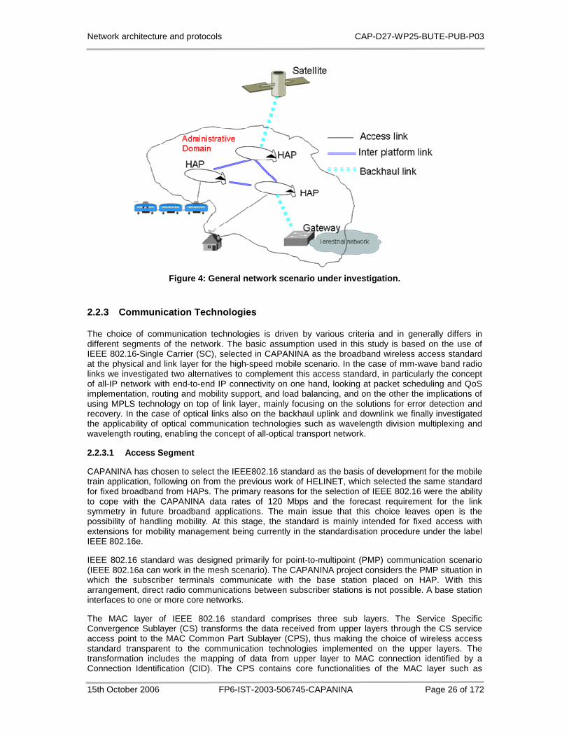
Network architecture and protocols CAP-D27-WP25-BUTE-PUB-P03
15th October 2006 FP6-IST-2003-506745-CAPANINA Page 26 of 172
Figure 4: General network scenario under investigat ion.
2.2.3 Communication Technologies
The choice of communication technologies is driven by various criteria and in generally differs in different segments of the network. The basic assumption used in this study is based on the use of IEEE 802.16-Single Carrier (SC), selected in CAPANINA as the broadband wireless access standard at the physical and link layer for the high-speed mobile scenario. In the case of mm-wave band radio links we investigated two alternatives to complement this access standard, in particularly the concept of all-IP network with end-to-end IP connectivity on one hand, looking at packet scheduling and QoS implementation, routing and mobility support, and load balancing, and on the other the implications of using MPLS technology on top of link layer, mainly focusing on the solutions for error detection and recovery. In the case of optical links also on the backhaul uplink and downlink we finally investigated the applicability of optical communication technologies such as wavelength division multiplexing and wavelength routing, enabling the concept of all-optical transport network.
2.2.3.1 Access Segment
CAPANINA has chosen to select the IEEE802.16 standard as the basis of development for the mobile train application, following on from the previous work of HELINET, which selected the same standard for fixed broadband from HAPs. The primary reasons for the selection of IEEE 802.16 were the ability to cope with the CAPANINA data rates of 120 Mbps and the forecast requirement for the link symmetry in future broadband applications. The main issue that this choice leaves open is the possibility of handling mobility. At this stage, the standard is mainly intended for fixed access with extensions for mobility management being currently in the standardisation procedure under the label IEEE 802.16e.
IEEE 802.16 standard was designed primarily for point-to-multipoint (PMP) communication scenario (IEEE 802.16a can work in the mesh scenario). The CAPANINA project considers the PMP situation in which the subscriber terminals communicate with the base station placed on HAP. With this arrangement, direct radio communications between subscriber stations is not possible. A base station interfaces to one or more core networks.
The MAC layer of IEEE 802.16 standard comprises three sub layers. The Service Specific Convergence Sublayer (CS) transforms the data received from upper layers through the CS service access point to the MAC Common Part Sublayer (CPS), thus making the choice of wireless access standard transparent to the communication technologies implemented on the upper layers. The transformation includes the mapping of data from upper layer to MAC connection identified by a Connection Identification (CID). The CPS contains core functionalities of the MAC layer such as
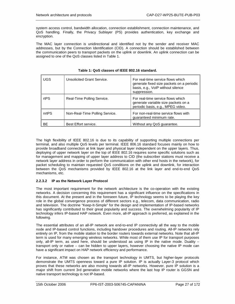
Network architecture and protocols CAP-D27-WP25-BUTE-PUB-P03
15th October 2006 FP6-IST-2003-506745-CAPANINA Page 27 of 172
system access control, bandwidth allocation, connection establishment, connection maintenance, and QoS handling. Finally, the Privacy Sublayer (PS) provides authentication, key exchange and encryption.
The MAC layer connection is unidirectional and identified not by the sender and receiver MAC addresses, but by the Connection Identification (CID). A connection should be established between the communication peers to transport packets on the uplink or downlink. An uplink connection can be assigned to one of the QoS classes listed in Table 1.
Table 1: QoS classes of IEEE 802.16 standard.
UGS Unsolicited Grant Service. For real-time service flows which generate fixed size packets on a periodic basis, e.g., VoIP without silence suppression.
rtPS Real-Time Polling Service. For real-time service flows which generate variable size packets on a periodic basis, e.g., MPEG video.
nrtPS Non-Real-Time Polling Service. For non-real-time service flows with guaranteed minimum rate.
BE Best Effort service. Without any QoS guarantee.
The high flexibility of IEEE 802.16 is due to its capability of supporting multiple connections per terminal, and also multiple QoS levels per terminal. IEEE 806.16 standard focuses mainly on how to provide broadband connection at link layer and physical layer independent on the upper layers. Thus, deploying of upper network layer on the top of IEEE 802.16 requires some specific solutions such as for management and mapping of upper layer address to CID (the subscriber stations must receive a network layer address in order to perform the communication with other end hosts in the network), for packet scheduling to maintain requested QoS conditions on the uplink and downlink, for interaction between the QoS mechanisms provided by IEEE 802.16 at the link layer and end-to-end QoS mechanisms, etc.
2.2.3.2 IP as the Network Layer Protocol
The most important requirement for the network architecture is the co-operation with the existing networks. A decision concerning this requirement has a significant influence on the specifications in this document. At the present and in the foreseen future, IP technology seems to be playing the key role in the global convergence process of different sectors e.g., telecom, data communication, radio and television. The doctrine “Keep-It-Simple” for the design and implementation of IP-based networks has significantly contributed to their great popularity and success. The overwhelming popularity of IP technology infers IP-based HAP network. Even more, all-IP approach is preferred, as explained in the following.
The essential attributes of an all-IP network are end-to-end IP connectivity all the way to the mobile node and IP-based control functions, including handover procedures and routing. All-IP networks rely entirely on IP, from the mobile station to the border routers towards external networks. Note that all-IP term is used for many emerging wireless networks. While most of them use IP for transport purposes only, all-IP term, as used here, should be understood as using IP in the native mode. Duality – transport only or native – can be hidden to upper layers, however choosing the native IP mode can have a significant impact on HAP network efficiency and performance.
For instance, ATM was chosen as the transport technology in UMTS, but higher-layer protocols demonstrate the UMTS openness toward a pure IP solution. IP is actually Layer-3 protocol which proves that these networks are also moving towards all-IP networks. However, pure IP solution is a major shift from current 3rd generation mobile networks where the last hop IP router is GGSN and native transport technology is not IP-based.

Network architecture and protocols CAP-D27-WP25-BUTE-PUB-P03
15th October 2006 FP6-IST-2003-506745-CAPANINA Page 28 of 172
Numerous reasons speak for all-IP architecture. Using IP technology as the foundation of HAP networks makes engineering and economic sense. Today, IP is prevalent fixed networking standard. The philosophy embodied in the IP has made it ubiquitous. The main aspects of this philosophy are simple and stateless networks, with complexity pushed to the edge. The IP network is modular, with open interfaces placed along functional boundaries. A single cabling and routing network that would support all mobile and fixed users, public and private, would be preferred choice for network operators from economic as well as engineering perspective. Finally, at the user level, it is expected that all end user applications will be IP-based. Applications available on fixed networks will inherently be available on mobile networks, without their characteristics being impaired by specific mobile protocols. The same will apply to terminals where only an IP stack will be necessary. It is the native use of IP that more readily allows for building an efficient network regardless of access technologies. As the coverage of native IP increases, the wireless-specific protocols are pushed farther toward the access segment.
2.2.3.3 MPLS
MPLS is a technology defined by IETF and ITU-T in order to enhance the capability of the IP core networks of service providers. That is, a domain consisting of MPLS routers can be established in the core of IP networks. At the ingress point of an MPLS domain, the ingress Label Edge Router (LER), packets are classified according to packet header information (e.g., source/destination address, service class, etc.) or according to network related information (e.g., ingress port) or combinations of both. A group of packets treated in the same way is called Forwarding Equivalence Class (FEC). It is also possible to bundle a set of FECs and use one single label for this union. This procedure is known as aggregation.
Then a unique locally significant fixed-length label is chosen for packets belonging to a certain FEC and attached to each packet. Subsequent Label Switching Routers (LSRs) examine the packets’ labels, replace them with already specified new labels, and forward the packets according to information stored in a table to the next LSR, until the egress point (egress LER) of the network is reached. The unidirectional path along which a packet traverses the MPLS domain is called Label Switched Path (LSP) and it can be considered a tunnel in some ways, since the packets entering the path are fast-forwarded until the end of the path by just looking at the labels.
The forwarding procedure (forwarding plane) is completely decoupled from the MPLS control plane which gives HAP network provider a lot of possibilities to influence the network’s behaviour. The control plane itself can be divided into two parts. One part, the label distribution protocol, is responsible for distributing labels to all LSRs along an LSP. Currently two different protocols are defined by the IETF: (i) RSVP-TE (RFC 3209), the Traffic Engineering extension for MPLS to the Resource reSerVation Protocol, and (ii) CR-LDP (RFC 3213), the Constraint-based Routing Label Distribution Protocol, which has been newly developed for MPLS. In February 2003 the IETF decided to discontinue work on CR-LDP, so the former one should be preferred.
Although basic traffic engineering can be achieved by manually defining LSPs (explicit routing), one central goal in networks with fixed nodes is to automatically choose an adequate LSP through the MPLS domain in order to achieve maximal utilization of the network and to meet service class requirements like delay or guaranteed bandwidth. Therefore, it consists of mechanisms which gather network state information and compute routes for LSPs. The CBR (Constraint Based Routing) mechanism can be used to efficiently use the resource of the network.
MPLS is recommended as an optional but important building block in the network architecture for CAPANINA HAP network, which is motivated by the following reasons. MPLS plays a significant role in the IP core of service providers' networks today because the traffic engineering feature of MPLS makes the cost-efficient utilization of networking resource possible. In addition, MPLS resilient mechanisms can help the HAP-based network service providers to cope (e.g.: reroute the affected connections/sessions to avoid failed links or network elements) with HAP-specific network failures, which are expected to be frequent in HAP networks having floating and/or flying base stations. It is worth mentioning that GMPLS (Generalized MPLS) can be used as the control plane solution for the HAP optical network comprising backhaul and inter-platform links.
Network architecture and protocols CAP-D27-WP25-BUTE-PUB-P03
15th October 2006 FP6-IST-2003-506745-CAPANINA Page 29 of 172
2.2.3.4 All-optical Transport Network
The concept of all-optical HAP-based transport network emerges from the possibility to extend the use of free-space optics from inter-platform links (IPLs) also to the backhaul uplink/downlink (UL/DL) between HAP and the fixed ground station. Recent CAPANINA trials achieved a remarkable 1.25 GBit/s downlink transmission from the stratosphere to an optical receiver on the ground over a maximum link distance of 64 km [16].
Due to demanding requirements to backhaul uplink and downlink between HAP and the fixed ground station hosting a gateway to external networks, which will have to carry the aggregate traffic load from/to several tens or hundreds of cells, at least one ground station is expected to be positioned in each HAP coverage area. Their number will actually have to be based on link budget calculation taking into account also the expected traffic load. Therefore, capacity boosting all-optical alternative to mm-wave transmission technology, based on wavelength division multiplex routing, has been investigated in order to avoid unnecessary conversions between optical and electronic domains, as well as its limitations and implications to the network topology.
2.3 Network Architecture Requirements and the Impac ts of Basic Assumptions
2.3.1 Service Requirements
In order to define the most suitable network architecture the set of candidate services and the implications of their provision need to be carefully assessed. Requirements should then be derived based on service characteristics and the required functionality.
A list of services that should be feasible via broadband HAP delivery are given in [17]. The range of candidate services identified therein is grouped with the requirements of each group as follows:
• Conversational services (e.g., voice and video telephony): they require data transfer with low delay and low delay variation, but may be more tolerant toward data loss depending on the applied encoding. Bandwidth requirements vary with the application (e.g. voice and/or video transfer).
• Streaming services (e.g., real time radio and television): they need low delay variation for the data transfer, but are less sensitive to delay and data loss, the latter depending on the applied encoding. Bandwidth requirements are usually high.
• Interactive services (e.g., the Web): their primary interest is low delay data transfer, and also minimal data loss, however, delay variation is not an issue. Their bandwidth consumption is usually not significant.
• Best-effort services (e.g., email and FTP): for them neither delay nor delay variation is an issue, however loss should be kept at a minimum level. Due to their best-effort nature bandwidth availability is not an issue.
These characteristics have to be considered when defining the network architecture. Even though the four service groups impose distinctively different requirements on the network, they share the need for some common functional entities. This need derives from the way an individual service is introduced, set up and operated in a network. The definition of the network architecture must also describe how these entities are realized.
The targeted HAP network must be able to operate in the following scenarios:
• The network architecture must be capable to provide broadband Internet and Intranet access for SOHO or SME with QoS support; the access services can be:
o Point-to-point
o Multicast

Network architecture and protocols CAP-D27-WP25-BUTE-PUB-P03
15th October 2006 FP6-IST-2003-506745-CAPANINA Page 30 of 172
o Broadcast
• The network architecture must be capable to provide private circuits for
o Interconnection of different networks, ISPs
o Backhaul link between a base station of a mobile cellular network and the core network
o Bearer link inside a core network
• The network architecture must support mobility to provide access link aggregate traffic points on trains and coaches.
2.3.2 Technical Requirements
In the following we list other technical requirements that need to be addressed in the phase of the network architecture definition:
• Provision of connectivity: must provide end-to-end connection between players. If HAP is used as an access network, it must connect end-users to the core network. In case of private circuits, the network architecture must be able to deliver data between two points. In the first case, interworking is needed with the core network while in the second case, interworking is necessary at both connected points.
• Relay or routing : mechanism to forward data packets from the sender to the receiver must be implemented. In a HAP network environment, where link failures may be heavily affected by bad weather conditions such as fog and rain, quick link failure detection and rerouting mechanism is required. Multicast routing is also a required feature to provide multicast and broadcast services and applications.
• Facilitation of the interworking between operators: today’s Internet consists of several domains; each of them is operated by separate network operator. Thus the interworking between operators is necessary in order to connect network domains to provide connectivity for wide areas. In case of HAP networks, the interworking between HAP network operators with other operators in the Internet is a required functionality which involves the specification of interfaces between operators. The authentication, authorization and accounting (AAA) interworking and mobility management is the problem subset in this area.
• Flexibility: the ultimate goal of any network is to provide services for users. Some services can be defined before deploying the network infrastructure. Other services may be derived according to the need of the market. Hence the development, deployment and provisioning of new services should be flexible in HAP networks.
• Control and management : the HAP networks will be controlled and managed by operators in order to provide non-interrupted services with predefined quality. To do that, the following functionalities should be developed and implemented in the network architecture:
o AAA: authentication, authorisation and accounting. Authentication is the mean to identify the subscribers of HAP network usually by username and password. The subscribers must be authenticated before gaining access to the HAP network and the offered services. Authorization functions give or deny the subscribers rights to access to the network resources after authentication. Finally, accounting is the process to keep trace of the subscriber usage statistics such as amount of data transferred, amount of time spent in the network, etc. These statistics can be used in other processes such as trend analysis, network planning, billing, etc.
o QoS: mechanisms are necessary to measure, improve and guarantee the agreed QoS parameters such as transmission rate, error rate, delay and other parameters.

Network architecture and protocols CAP-D27-WP25-BUTE-PUB-P03
15th October 2006 FP6-IST-2003-506745-CAPANINA Page 31 of 172
o Mobility and roaming: an important objective of CAPANINA is to provide network access for trains and coaches with speed up to 300 km/h. Then mechanisms are needed to provide connection handover from one HAP to another (roaming). The network connection of a mobile user should be non-interrupted, same as for a fixed user. To do this, a centralized AAA and mobility management mechanisms are required.
o Network management: besides the network management features of a traditional network, we need to identify the additional management features necessary for the HAP network such as HAP specific management, subscriber station management, mobility related network management.
• Cooperation with existing networks: the HAP network in most cases will not operate in a standalone manner; it should be integrated with other networks to provide end-to-end connections. Then the network architecture should be specified for easy integration with existing networks.
• The use of COTS equipments: it is not reasonable if the equipment to be deployed and operated in the HAP networks is developed from scratch. Buying COTS equipment and integrating it is much more viable and cost efficient solution.
• Authentication support for roaming: IEEE 802.16 supports authentication facility in the MAC layer. However, this authentication is per-terminal. In some service scenarios, the per-user authentication should be required. Moreover, IEEE 802.16 supported authentication mechanism is local and static, meaning that each base station has its own preconfigured terminal database. From network and service management point of view, a centralized database of subscriber information is a must. Furthermore, the roaming services require user information exchange between the base stations and the centralized user information database.
• Security in MAC and/or in upper layer: the IEEE 802.16 standard supports data encryption. However, the security vulnerability of IEEE 802.11 standard raises the question of the suitability of such security mechanisms in protecting user data. In this respect we have two alternatives to choose from: enhance the security mechanism by e.g. frequently changing of encryption keys, or use the network layer security mechanism.
2.3.3 HAP Specific Requirements
Finally, the network architecture definition also needs to take into account a set of requirements specific for telecommunication systems based on HAPs:
• Reduce payload and energy consumption onboard: the smaller the payload, the lower the HAP’s production and operation cost. The floating aerial platforms will be supplied by solar cells. Therefore, a continuous operation of the platform especially at night will depend on the power consumption onboard. Defining network layer in user, control and management plane requires consideration of the trade-off between the weight of the payload on-board, energy consumption and the number of networking functionalities. That is, any increase of the number and complexity of functionalities will increase the weight of the payload onboard and the energy consumption at the same time.
• HAP management : the management of the HAP networks contains additional tasks as compared to the management of traditional networks. HAPs as flying objects in the stratosphere reveal several operation and maintenance activities. For instance, the altitude, the location and the energy of the HAPs should be easily monitored and controlled. After an operational period, the HAP should be brought back to the ground for maintenance purposes.
• Security : experiences gained from the deployment of Wi-Fi hotspots suggest that security and user data protection should be carefully considered. Data communication, mainly on the wireless access link, should be secured in such a way that makes unauthorised data access become impossible or very hard task.
Network architecture and protocols CAP-D27-WP25-BUTE-PUB-P03
15th October 2006 FP6-IST-2003-506745-CAPANINA Page 32 of 172
• CPE/TE: the complexity level of the CPE/TE is an open issue. CPE/TE can contain lots of functionalities to reduce the complexity of the HAPs. In this case, the cost of CPE/TE production may increase dramatically. On the contrary, if we want to keep CPE/TE to be simple, the production cost can be low but the number of functionalities on-board will increase. Should CPE/TE manage the traffic of only one subscriber or should the case of multiple subscribers behind the CPE/TE be considered? For instance, the end-users on the train scenario may belong to one subscriber or they can be different subscribers.
2.3.4 Impacts of Basic Assumptions
On service requirements : IP-based networks can support different type of services if Quality of Service is supported to guarantee different quality requirements of the services. IP multicasting in the whole HAP network and the link-layer broadcasting at the access wireless link is required to support multicast and broadcast scenarios. With IP in the network layer, interconnection with different networks, backhaul link service and bearer link service can be easily provided.
On technical requirements : Existing IP-based AAA standards such as Diameter (RFC 3588), RADIUS (RFC 2865) and TACACS (RFC 1492) can be readily used for HAP networks. Selecting the most suitable AAA protocol among them for the use in HAP networks is one of important tasks to be carried out. IP intra-domain and inter-domain routing protocols can be used for forwarding data packets from its source to destination. However, the consideration of more efficient routing or switching mechanisms, suitable for HAP network, is a must because of the possible high probability of network errors. Specifying suitable Operational Support System (OSS) should be another important task to support effective network management and operation. Finally, suitable mobility management mechanisms are needed for the operation of CAPANINA HAP networks.
On HAP-specific requirements : Currently there are several existing IP-based network management systems. Selecting the most suitable one for CAPANINA HAP network and specifying HAP-specific parameters for control and monitoring is an important task. Security issues, especially key management mechanisms, also need to be carefully considered. Finally, the functionality of the CPE/TE and their design is another important task.

Network architecture and protocols CAP-D27-WP25-BUTE-PUB-P03
15th October 2006 FP6-IST-2003-506745-CAPANINA Page 33 of 172
2.4 Summary
This chapter provided the basic assumptions which are the essential starting points for building the network architecture. Firstly, we provided the business models describing the information exchange and co-operation between business actors in different service scenarios. Secondly, different possible network scenarios were identified and the most probable, a general network scenario containing inter-platform links and back-haul links is selected for our further analysis. Thirdly, the assumptions about the essential network technologies were provided: IEEE802.16 is selected as the broadband wireless access technology and IP as the network layer protocol for CAPANINA. MPLS and All-Optical networks are identified as optional but effective technologies to be taken into consideration for the specification of the network architecture.
Considering the requirements of the network architecture specified in [19] and taking into account the basic assumptions, the following HAP-specific problems to be addressed are identified:
• Quality of Service.
• Suitable AAA standards.
• Routing or switching protocols capable for quick error detections an recovery.
• Mobility management.
• Network management.
• Operational Support System (OSS).
• Design of CPE/TE.
• Security and key management.
All problems identified and listed above require more detailed investigation in the process of specification of HAP network architecture. However, due to limited time and human resources available for the WP2.5 of the CAPANINA project, we selected a subset of CAPANINA scenario specific issues for further in-depth investigation. Quality of service, mobility management, routing or switching protocols capable for quick error detections an recovery, and network management were identified as primary areas to be considered and are addressed in the following chapters, as they were originally proposed for investigation in the Technical Annex of the project, as well as the problems related to all-optical networking, which based on the successful second year CAPANINA trial emerges as a potential solution for high-speed data communication for inter-platform and backhaul links. . The remaining areas, not investigated in detail in the frame of WP2.5 but essential for the conclusive specification of the network architecture, include the selection of suitable AAA standard, suitable OSS, design of CPE/TE and security and key management.
Network architecture and protocols CAP-D27-WP25-BUTE-PUB-P03
15th October 2006 FP6-IST-2003-506745-CAPANINA Page 34 of 172
3 QoS Considerations
3.1 Introduction
To satisfy different performance requirements of heterogeneous applications and services, QoS support is required. In this chapter, a hybrid end-to-end QoS architecture comprising both IntServ and DiffServ is proposed to ensure the scalability and compatibility while satisfying the quality requirements of candidate services and applications for CAPANINA HAP networks: DiffServ should be used in the core network because of its high-degree scalability and both DiffServ and IntServ should be provided at the access links to provide end-users the possibilities to choose the most appropriate QoS scheme for their applications.
DiffServ and IntServ are already implemented in several commercial products. Moreover, several studies of the operations of IntServ over DiffServ have been carried out, e.g. in (RFC 2998), [40], [41]. In this documentation, we will not investigate how to implement IntServ over DiffServ or how to map from a class of one QoS architecture to the corresponding class of another QoS architecture (already was considered in IST HELINET project [43]). Instead, we will focus on the problems raising in the implementation of IntServ-DiffServ hybrid QoS architecture in the HAP networks.
As mentioned in Chapter 2, IEEE 802.16-SC is the wireless access technology selected for CAPANINA HAP networks. Connections of its MAC layer are unidirectional and identified not by the sender and receiver MAC addresses, but by the Connection Identification (CID). A connection should be established between the communication peers to transport packets on the uplink or downlink.
At the wireless access link, we have to implement the hybrid QoS architecture on the top of the IEEE 802.16-SC MAC layer. This will be the main problem space to be considered.
The main motivation of this chapter is to find the solutions for the following problems. Firstly, IEEE 802.16 standard does not specify the call admission control and packet scheduling mechanism to implement its QoS architecture in the link layer. Selecting appropriate call admission control and packet scheduling would be QoS implementation task. The problem becomes more challenging if the applied adaptive coding and modulation is taken into account and therefore, the link’s bit rate is variable.
Secondly, we have to address the issues related to the efficient transferring of IP-layer QoS signalling traffic over 802.16 wireless access link. Three issues are identified in this area:
• How to process and forward the RSVP signalling messages over the wireless access link?
• How to carry QoS traffic classes on wireless access downlink?
• QoS issues related to mobility.
Thirdly, there are state-of-the-art forwarding and routing technologies such as MPLS and ToS routing with different features and advantages. The question is how these technologies themselves or combinations of them and DiffServ, which is proposed to be deployed in both the access and core networks, can support QoS efficiently.
3.2 Selected QoS Architecture for the CAPANINA HAP Networks and Implementation Solutions
Other QoS mechanisms exist in lower layer such as the QoS support in ATM networks; however, the QoS mechanisms in layers lower than IP layer alone cannot give adequate scalability and flexibility. Consequently, QoS support in IP layer should be considered for the HAP networks. There exist two well-known QoS architectures in the IP layer: IntServ (RFC 1633) and DiffServ (RFC 2475). In the following, a hybrid architecture comprising IntServ and DiffServ is considered for CAPANINA HAP networks.
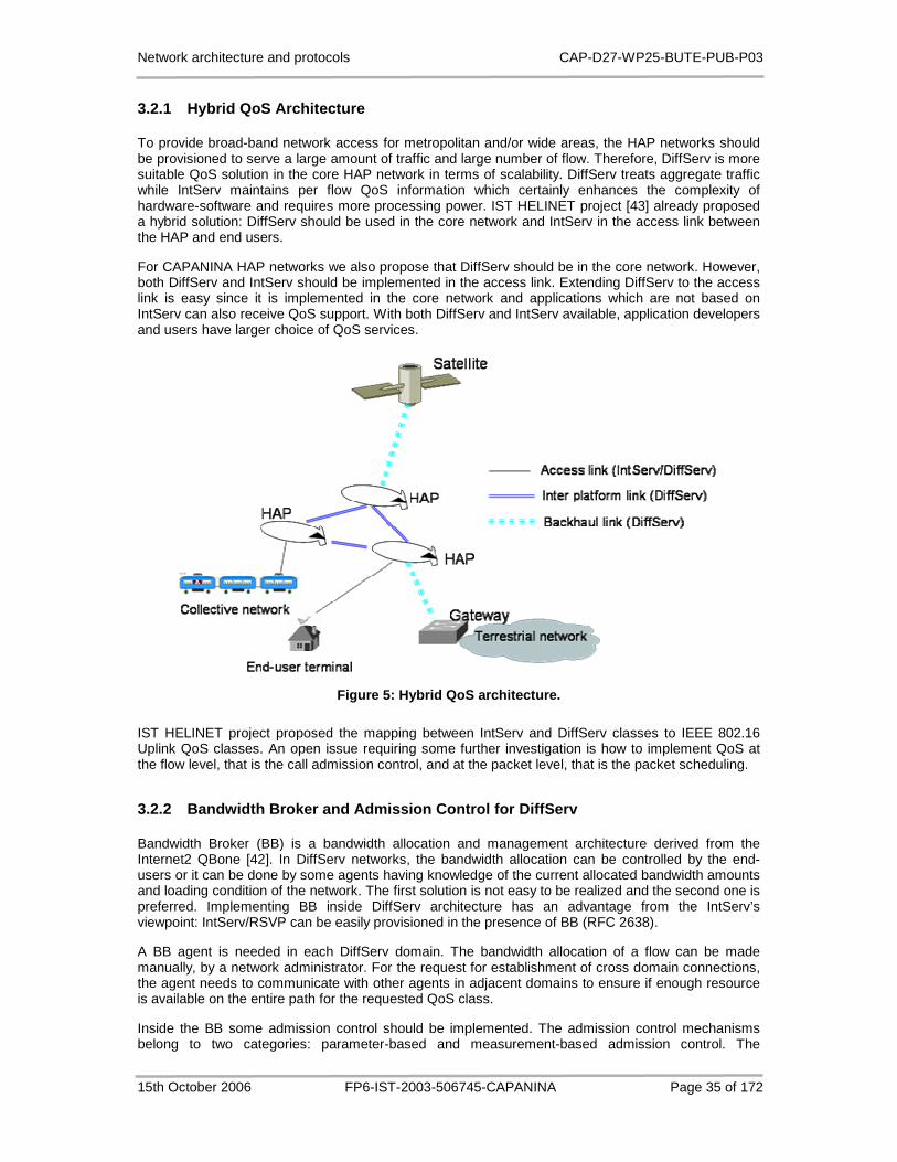
Network architecture and protocols CAP-D27-WP25-BUTE-PUB-P03
15th October 2006 FP6-IST-2003-506745-CAPANINA Page 35 of 172
3.2.1 Hybrid QoS Architecture
To provide broad-band network access for metropolitan and/or wide areas, the HAP networks should be provisioned to serve a large amount of traffic and large number of flow. Therefore, DiffServ is more suitable QoS solution in the core HAP network in terms of scalability. DiffServ treats aggregate traffic while IntServ maintains per flow QoS information which certainly enhances the complexity of hardware-software and requires more processing power. IST HELINET project [43] already proposed a hybrid solution: DiffServ should be used in the core network and IntServ in the access link between the HAP and end users.
For CAPANINA HAP networks we also propose that DiffServ should be in the core network. However, both DiffServ and IntServ should be implemented in the access link. Extending DiffServ to the access link is easy since it is implemented in the core network and applications which are not based on IntServ can also receive QoS support. With both DiffServ and IntServ available, application developers and users have larger choice of QoS services.
Figure 5: Hybrid QoS architecture.
IST HELINET project proposed the mapping between IntServ and DiffServ classes to IEEE 802.16 Uplink QoS classes. An open issue requiring some further investigation is how to implement QoS at the flow level, that is the call admission control, and at the packet level, that is the packet scheduling.
3.2.2 Bandwidth Broker and Admission Control for Di ffServ
Bandwidth Broker (BB) is a bandwidth allocation and management architecture derived from the Internet2 QBone [42]. In DiffServ networks, the bandwidth allocation can be controlled by the end-users or it can be done by some agents having knowledge of the current allocated bandwidth amounts and loading condition of the network. The first solution is not easy to be realized and the second one is preferred. Implementing BB inside DiffServ architecture has an advantage from the IntServ’s viewpoint: IntServ/RSVP can be easily provisioned in the presence of BB (RFC 2638).
A BB agent is needed in each DiffServ domain. The bandwidth allocation of a flow can be made manually, by a network administrator. For the request for establishment of cross domain connections, the agent needs to communicate with other agents in adjacent domains to ensure if enough resource is available on the entire path for the requested QoS class.
Inside the BB some admission control should be implemented. The admission control mechanisms belong to two categories: parameter-based and measurement-based admission control. The

Network architecture and protocols CAP-D27-WP25-BUTE-PUB-P03
15th October 2006 FP6-IST-2003-506745-CAPANINA Page 36 of 172
parameter-based admission control algorithms are simple and easy to implement but is not efficient in resource utilization. Measurement-based admission algorithms estimate the current load of the network periodically; therefore, result in higher resource utilization but they are more complicated. Considering the IEEE 802.16 wireless access link with variable bit rate, a modified version of measurement-based admission control is needed for efficient resource utilization. We will discuss about this in Section 3.4.
In a DiffServ network with BBs, the IntServ RSVP signalling messages can be processed and forwarded as follows. In each DiffServ domain, the PATH messages are identified by leaf-routers and forwarded to the BB which calculates and updates the corresponding fields in the PATH messages and forward them to the next DiffServ domain on the path. When the RESV messages come back, they also be forwarded to the BB and necessary resource is allocated for the flow (Figure 6).
Figure 6: Processing and forwarding of RSVP message s with BB.
3.3 APS: a Packet Scheduling Algorithm for High Sys tem Throughput on the Access Link
In wired networks, QoS requirements are typically satisfied by a combination of resource reservation (at the flow level) and fair resource allocation/packet scheduling (at the packet level). However, in wireless environments of scare and shared nature, user mobility and a signal-to-noise ratio -SNR- (characterizing channel conditions) dynamically changes, which makes it very difficult to perform either resource reservation or fair packet scheduling. Thus effective packet scheduling algorithms should consider channel conditions in order to enhance system performance. It has been shown that General Processor Sharing (GPS) [21] and Packet Fair Queuing (PFQ) [22] algorithms can not simultaneously provide fairness and guaranteed service in wireless networks in spite of a fact that they perform well in wired networks.
The scheduling disciplines in wired networks are not directly applicable to wireless networks as wireless channel characteristics are completely different than that of wired channel in following viewpoints:
1. Wireless link is more prone to errors and the errors usually occur in bursts.
2. Wireless channel capacity is variable and location dependent because of interference, fading and shadowing.
3. Wireless bandwidth is limited.
4. Mobility of users gives more dynamics and variability in the system (in case of mobile networks).
5. Power constraint for mobile terminals (in case of mobile networks)
In order to tackle these issues in wireless environments, some desired properties should be defined for wireless scheduling. In [25], William K. Wong et al. introduced some of the desired properties for scheduling algorithm in wireless environments, namely: 1) Efficient bandwidth utilization; 2) Bounded

Network architecture and protocols CAP-D27-WP25-BUTE-PUB-P03
15th October 2006 FP6-IST-2003-506745-CAPANINA Page 37 of 172
delay; 3) Fairness; 4) Low complexity; 5) Heterogeneous traffic support; 6) Graceful service degradation; 7) Cooperation with connection admission control (CAC); 8)Interoperability
Several wireless fair queuing algorithms have been developed which provide varying degrees of short-term and long-term fairness, short-term and long-term throughput bounds, average case and worst case delay bounds, and graceful degradation for flows in the presence of channel error. Some of them were investigated and compared in [23] [24], in those works the wireless channel is modelled with two states: error-free and erroneous. Sessions in error state will offer their service share to sessions in the error-free state and claim it back when they switch to the error-free state.
As can see in [23] [24], there is no scheduling algorithm, which achieves all the desired qualities of wireless scheduling. There is always a trade-off in doing so.
In the previous works, the wireless channel is modelled with two states: error-free and erroneous. Sessions in error state will offer their service share to sessions in the error-free state and claim it back when they switch to the error-free state. Recently, different adaptive mechanisms such as adaptive modulation and channel coding have been proposed to enhance system capacity. The channel can be in multiple states and each state is assigned with a combination of mechanisms called a burst profile to maximize the data rate while maintain the bit error rate (BER) under a certain threshold. Some works on the packet scheduling focused on satisfying requirements of different QoS classes but they did not consider the dynamics of the wireless channel’s condition.
The 802.16 standard did not specify how to schedule packets in order to achieve QoS restrictions and high system performance. In 802.16, adaptive modulation and channel coding have been proposed to enhance system capacity. The channel can have multiple states and each state is assigned with a combination of mechanisms called burst profile to maximize the data rate while maintain the bit error rate (BER) under a certain threshold. We investigate packet scheduling in multi-state down-link wireless channel of IEEE 802.16 W-MAN networks operating in point-to-multi-point communication scenario. In this work, we introduce the system and channel model for systems with adaptive channel coding and modulation. With cross-layer design approach we propose a scheduling algorithm called Adaptive Profile Scheduling (APS), which takes into account different wireless channel conditions observed by different subscriber stations to enhance the system throughput while preserving the property of the long-term fairness and the guaranteed rate for each user.
3.3.1 System Model
Consider a wireless network with a base station (BS) and maximum N subscriber stations (SS) working in point-to-multi-point communication scenario. The data packets are segmented into fixed size ARQ (Automatic Repeat reQuest, a link-layer error control mechanism supported by IEEE 802.16) blocks and scheduled on the downlink with Time Division Multiplexing (TDM) and Adaptive Burst Profile [38]. Data to be sent to SSs are multiplexed in TDM frames which size is S symbols.
In our model, data will arrive to a user queue with given rate that can be guaranteed rate in case of real-time applications, or minimum rate in case of non real-time applications. We don’t consider the traffic type with hard delay bound. We also assume that one new connection just only is accepted by Connection Admission Control (CAC) when BS can satisfy the requirements of coming connection while maintains the performance of the system.
An SS measures the received signal level sent by the BS and decides which burst profile is the best for its downlink transmission. The burst profile change request then can be sent to the BS on the up-link. Let BP is the set of predefined burst profiles. At any point of time, each SS is assigned with a burst profile which consists of a modulation and a channel coding technique, i.e. for the SS i at time
frame k ; a burst profile ( )kibp , is chosen from BP with that a symbol can carry )),(( kibpbps bytes of data. We assume that the chosen burst profile is efficient enough to transfer data successfully to the SS.
At each frame, e.g. at frame k, the BS with a given set of SSs and their assigned burst profiles must decide how to transfer data. That is, ),( kin symbols are assigned to SS i to carry its data, where

Network architecture and protocols CAP-D27-WP25-BUTE-PUB-P03
15th October 2006 FP6-IST-2003-506745-CAPANINA Page 38 of 172
∑=
≤N
i
Skin1
),( (3.1)
The data amount of all SS i packet in frame k : )),((),(),( kibpbpskinkiD =
The data amount of all SS-s packed in frame k can be calculated as
∑∑==
==N
i
N
i
kibpbpskinkiDkD11
)),((),(),()( (3.2)
which has an upper bound:
{ }l. l,kbpbpskbpbps
i, i,kbpkbp
S,kbpbpskDmaxkD
best
best
best
∀≥∀∈
==
))(())((
)()(
))(())(()(max
(3.3)
Therefore, the average amount of data per frame taken over m frame:
),(
),( 1
m
jiDmiD
m
javg
∑ == , for SS i ; (3.4)
m
kDmD
m
kavg
∑ == 1)(
)( , for all SSs; (3.5)
The throughput fairness index is defined according to Jain et al. [28].
∑∑
=
==N
i avg
N
i avg
miDN
miDmI
1
2
1
2
),(
)),(()( ; (3.6)
The throughput fairness index takes values between 0 and 1. The closer the index is to 1, the fairer the scheduling.
3.3.2 The Adaptive Profile Scheduling
In our model, the channel can have multiple states (see the channel model in Appendix E) and each state is assigned with a combination of mechanisms called burst profile to maximize the data rate while maintain the bit error rate (BER) under a certain threshold. We investigate packet scheduling in multi-state down-link wireless channel operating in point-to-multi-point communication scenario. In this section, a novel wireless scheduling algorithm known as the Adaptive Profile Scheduling (APS) algorithm (developed continuously in [1], [2], [3]) is proposed.

Network architecture and protocols CAP-D27-WP25-BUTE-PUB-P03
15th October 2006 FP6-IST-2003-506745-CAPANINA Page 39 of 172
3.3.2.1 Motivation and Contribution of APS
In wireless networks downloading users may experience that the wireless link is the bottleneck for their flows. In this case packet scheduling algorithms reassign slots in order to improve the overall download performance of the BS. Reassignment can be done according to a fair distribution or a dynamic priority distribution among the SSs. The first mechanism may not be efficient enough to improve the throughput. The second mechanism puts the fairness at a disadvantage assuming that all users receive the same (best effort) service.
In packet scheduling, it is often a trade-off in attempting to achieve the desired qualities of wireless scheduling. Moreover, the requirement for low complexity and scalability limits the number of practical scheduling algorithms available for implementation, with weighted round robin and simple priority scheduling being recognized as two of the most scalable algorithms available as of the present moment.
Consider to the dynamics of the wireless channel’s condition, we propose the Adaptive Profile Scheduling (APS) in order to enhance system performance.
As specified at the beginning of Section 3.3, there were several objectives put forth in the selection of a desired wireless scheduling algorithm. It is virtually impossible to propose a scheduling algorithm that befits every single objective, however, with this in mind, specific qualities which it is felt to be more essential was put into thought upon the formulation of APS.
APS, provides a solution by dynamic priority assignment for the SSs. In order to provide fairness and high utilization it assigns the priority level to the SSs according to their burst profile. Thus APS allocates more slots for SSs with good burst profile improving the performance.
Since APS works on SS queues that receive the same (best effort with guaranteed bandwidth) service the algorithm must be aware of the allocation of the slots. If the error conditions let the BS distribute slots in a fair manner (e.g. no SS is blocked permanently) then APS must share slots fairly among the SSs. To sum up, the objective of APS is to:
• Provide a throughput guarantee of ir for each SS i .
• Achieve high wireless channel utilization-Enhance the overall throughput.
• Guarantee long term fairness.
• Simple implementation and algorithm complexity.
3.3.2.2 Adaptive Profile Scheduling
Consider BS with N flows entering the scheduler from SSs in Point-to-Multipoint (PMP) scenario, each flow will be accepted to BS with predefined traffic rate, and will be assigned with a FIFO buffer at the BS. The MAC packets to be sent to the SSs are classified according to their receiver SS address and put into the corresponding FIFO buffers. Buffer management is implemented at the queues to buffer a fixed number of packets and packets exceeding the queue length are dropped. Packets leave the queues when they are serviced. The data packets are segmented into fixed size ARQ blocks and scheduled on the downlink with Time Division Multiplexing (TDM). Data to be sent to SSs are multiplexed in TDM. It can be seen from the network node that there can be two scenarios arising from the rate at which the packets are entering into the scheduler.
The main principle of APS is that the SS with better burst profile (higher bps) should borrow resources from the SS with worst burst profile and gives back the borrowed resources when its channel condition is bad. This main principle is combined with some mechanisms to guarantee the minimum rates and fairness. Two token buckets is used: the first token bucket is for the minimum rate guarantee and the second one is for the fairness guarantee purpose.
Denote the FIFO buffer assigned to SS i for storing MAC packets by iqueue . The actual sizes of the
first and second token bucket are 1it and 2it , respectively. The depth of the token buckets is upper

Network architecture and protocols CAP-D27-WP25-BUTE-PUB-P03
15th October 2006 FP6-IST-2003-506745-CAPANINA Page 40 of 172
bound ( 1max and 2max ). A ir is used for the minimum rate guarantee for SS i . Slots of each TDM time
frame are distributed among SSs after five steps:
• In the first step, adequate slots are reserved according to the guaranteed minimum rate of each SS using the first token bucket.
• The second step guarantees the long-term fairness for each SS by limiting the borrowed slots. If there is user with 2it exceeds the 2max threshold, then amount of data according to
exceeded amount (one token in the 2. bucket is assigned with one symbol of the frame).
• The third step enhances the system throughput by give higher privilege to SSs with better burst profile. The distribution of remained slots is based on the remained tokens in the second bucket and the data in queue of each user. The user with higher burst profile will get better change to send out its data as much as it can.
• In the fourth & fifth step, the token buckets are refilled.
The first bucket is refilled once in a rough, but the second can be refilled more than once as the following step of the second and the third steps. Those three steps can be repeated as much as can be in order to solve the starve problem: there are cases, in which some user has data but they haven’t got enough tokens in the second bucket to send out, but there are some users, they haven’t data, but they have enough tokens. Those unused tokens can be redistributed; hence users can borrow tokens from others to send out their data, and will be pay later in other redistribution rough. By this, we can maintain the long-term fairness of the system.
Algorithm 1 Description of the APS
{step 1 – For minimum rate guarantee}
filledsymno = 0
for i = 1 to N do reserve
=
)),((,
)),((min
kibpbps
data
kibpbps
ts ii1
ifor SS i
isofilledsymn =+ ;
))},((*,,min{ kibpbpsstdatat ii1ii1 =−
{ })),((*,min kibpbpssdatadata iii =−
end for
if Sofilledsymn = then
goto step 5
end if
{step 2 – For long-term fairness}
0=osharedsymn
for i=1 to N do
if 0 and >> i2i2 datamaxt then reserve for SS i
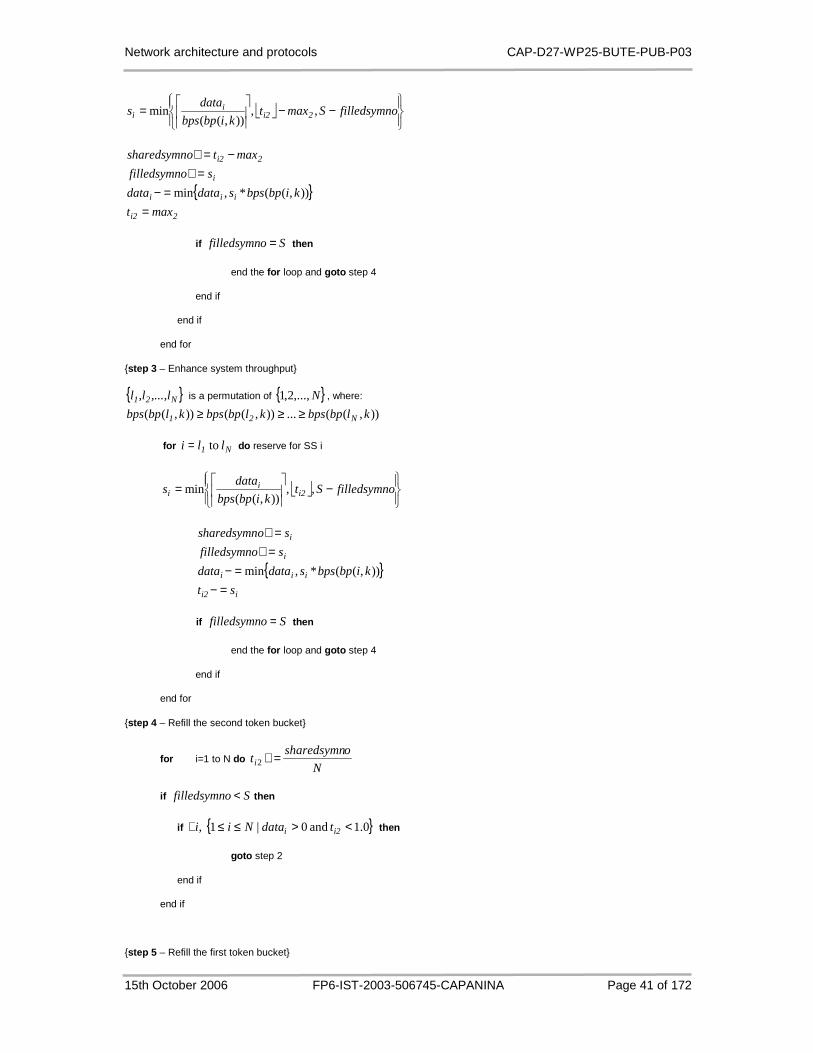
Network architecture and protocols CAP-D27-WP25-BUTE-PUB-P03
15th October 2006 FP6-IST-2003-506745-CAPANINA Page 41 of 172
−−
= ofilledsymnSmaxt
kibpbps
datas 2i2
ii ,,
)),((min
{ }2i2
iii
i
2i2
maxt
kibpbpssdatadata
sofilledsymn
maxtosharedsymn
==−
=+−=+
)),((*,min
if Sofilledsymn = then
end the for loop and goto step 4
end if
end if
end for
{step 3 – Enhance system throughput}
{ }N21 ,...,l,ll is a permutation of { }N,...,2,1 , where:
)),((...)),(()),(( klbpbpsklbpbpsklbpbps N21 ≥≥≥
for N1 lli to= do reserve for SS i
−
= ofilledsymnSt
kibpbps
datas i2
ii ,,
)),((min
{ }ii2
iii
i
i
st
kibpbpssdatadata
sofilledsymn
sosharedsymn
=−=−
=+=+
)),((*,min
if Sofilledsymn = then
end the for loop and goto step 4
end if
end for
{step 4 – Refill the second token bucket}
for i=1 to N do N
osharedsymnti =+2
if Sofilledsymn < then
if { }0.1 and 0|1 , <>≤≤∃ i2i tdataNii then
goto step 2
end if
end if
{step 5 – Refill the first token bucket}

Network architecture and protocols CAP-D27-WP25-BUTE-PUB-P03
15th October 2006 FP6-IST-2003-506745-CAPANINA Page 42 of 172
for i=1 to N do
+=
8
*1000*,min
frametimertmaxt ii11i1
end for
Based on those viewpoints, we can say that APS performs well the desired properties, which are mentioned previously. We will see this in the following section by some simulation results.
3.3.3 Simulation Results
In this section, some simulation results are done to illustrate the throughput improvement and the fairness of the APS. The algorithm was implemented in the ns-2 network simulator [3] with parameters shown in Table 2. Note that queuing models [29] may be applied for our case, however, it is out of the scope of the present work.
The channel model in Appendix E gives the basis for the performance evaluation. In this case, the wireless channel quality is characterized by the received SNR which is partitioned into 6 intervals with the thresholds of 610 A,...,A,A shown in Table 3, as suggested by Li et al. [27]. Six burst profiles as
shown in Table 4 are assigned to these intervals with different bps parameters. Time variation of the signal levels is characterized by Doppler frequency effect caused by the motion of subscriber stations.
Table 2: Channel conditions.
NAME VALUE
TDM frame size (S) 2000 symbol
Channel capacity 2 Mbaud/s
Average SNR(γ) 12 dB
Doppler frequency df 10 Hz
The state transition of the Markov chain happens in the frame time basis with the normalized transition
probabilities jip , shown in Table 5 calculated as presented in Section E based on simulated
parameters of channel conditions in Table 2. In other words, jip , is the probability that the channel
state changes to burst profile j given the previous state is i and the Doppler frequency is 10 Hz. A transition probability equals to the corresponding normalized probability multiplying the Doppler frequency.
Figure 7: The state transition between the Markov c hain’s states.
As shown in Figure 8, the improvement of the average throughput can be as high as 23.14 % with 400 kB/s guaranteed bandwidth values. With different guaranteed bandwidth, the improvement can be 22.17 % for the 600 kB/s case and 20.66 % for the 800 kB/s case.

Network architecture and protocols CAP-D27-WP25-BUTE-PUB-P03
15th October 2006 FP6-IST-2003-506745-CAPANINA Page 43 of 172
The simulation results show APS shares symbols fairly among the SSs. The smaller the guaranteed bandwidth the higher the number of unassigned slots is. APS shares these unassigned slots effectively since users with good burst profiles receives more slots than users with a bad profile does. Thus, the higher the number of unassigned slots the higher the throughput of the system.
Table 3: SNR thresholds.
SNR THRESHOLD VALUE (dB)
0A 0
1A 6.1
2A 8.8
3A 11.6
4A 16.7
5A 18
6A ∞
Table 4: Parameters of burst profiles.
BURST PROFILE ID INTERVALS BYTES PER SYMBOL (BPS) RATIO
bp0 ( 0A , 1A ] 24
bp1 ( 1A , 2A ] 36
bp2 ( 2A , 3A ] 48
bp3 ( 3A , 4A ] 72
bp4 ( 4A , 5A ] 96
bp5 ( 5A , 6A ) 108
Table 5: Transition probabilities of the Markov cha in.
PROB. VALUE PROB. VALUE
p01 0.0027 p10 0.0089
p12 0.0085 p21 0.0103
p23 0.0094 p32 0.0071
p34 0.0056 p43 0.0047
p45 0.0044 p54 0.0075
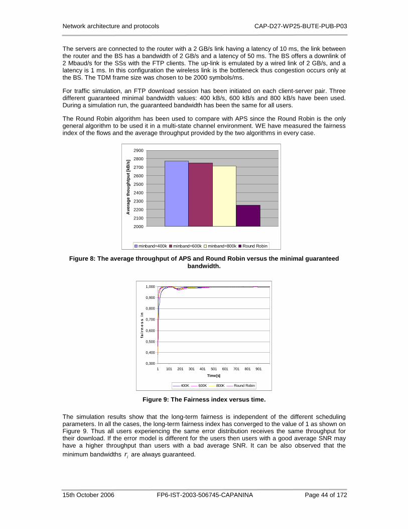
Network architecture and protocols CAP-D27-WP25-BUTE-PUB-P03
15th October 2006 FP6-IST-2003-506745-CAPANINA Page 44 of 172
The servers are connected to the router with a 2 GB/s link having a latency of 10 ms, the link between the router and the BS has a bandwidth of 2 GB/s and a latency of 50 ms. The BS offers a downlink of 2 Mbaud/s for the SSs with the FTP clients. The up-link is emulated by a wired link of 2 GB/s, and a latency is 1 ms. In this configuration the wireless link is the bottleneck thus congestion occurs only at the BS. The TDM frame size was chosen to be 2000 symbols/ms.
For traffic simulation, an FTP download session has been initiated on each client-server pair. Three different guaranteed minimal bandwidth values: 400 kB/s, 600 kB/s and 800 kB/s have been used. During a simulation run, the guaranteed bandwidth has been the same for all users.
The Round Robin algorithm has been used to compare with APS since the Round Robin is the only general algorithm to be used it in a multi-state channel environment. WE have measured the fairness index of the flows and the average throughput provided by the two algorithms in every case.
2000
2100
2200
2300
2400
2500
2600
2700
2800
2900
Ave
rage
thou
ghtp
ut [k
B/s
]
minband=400k minband=600k minband=800k Round Robin
Figure 8: The average throughput of APS and Round R obin versus the minimal guaranteed bandwidth.
0,300
0,400
0,500
0,600
0,700
0,800
0,900
1,000
1 101 201 301 401 501 601 701 801 901
Time[s]
fair
ne
ss
in
de
x
400K 600K 800K Round Robin
Figure 9: The Fairness index versus time.
The simulation results show that the long-term fairness is independent of the different scheduling parameters. In all the cases, the long-term fairness index has converged to the value of 1 as shown on Figure 9. Thus all users experiencing the same error distribution receives the same throughput for their download. If the error model is different for the users then users with a good average SNR may have a higher throughput than users with a bad average SNR. It can be also observed that the minimum bandwidths ir are always guaranteed.

Network architecture and protocols CAP-D27-WP25-BUTE-PUB-P03
15th October 2006 FP6-IST-2003-506745-CAPANINA Page 45 of 172
3.3.4 Carrying QoS Traffic on the Wireless Access D ownlink
IEEE 802.16 standard does not specify the scheduling services on the downlink; therefore, it is still open question: what is the efficient scheduling scheme to carry IntServ and DiffServ data traffic on the downlink?
Basically, to carry IP-layer packets to the end-users on the downlink, we have to establish one or more MAC-layer connection. The packets of an IntServ flow are mapped into correspondent DiffServ classes by marking the ToS field in IP header by DiffServ code points. At the HAP where the receiver is attached to, these IntServ packets are identified by e.g. source and/or destination address and port. Here, we have two solutions to carry the IntServ traffic on the downlink: (1) The IntServ packets are treated as the DiffServ ones, that is, we do not differentiate the IntServ packets from the DiffServ packets. (2) The IntServ packets are treated differently: separate MAC connections are established to carry IntServ packets.
We prefer solution (1) because it makes the scheduling service more simpler than (2) because (1) requires only the scheduling for DiffServ classes while (2) needs scheduling for DiffServ traffic and IntServ traffic at the same time.
For solution (1) the data from traffic classes with priority higher than best-effort are schedule with the using of token buckets. The token rate and token buffer length depend on a resource allocation strategy determined by the network administrator. The overflowed packets from data queue with higher priority are remarked as best-effort traffic which is scheduled by APS. MAC packets are classified according to the actual burst profile (DIUC) after scheduling and then packed to the TDM frame to be sent over the air.
Figure 10. Packet scheduling at access wireless dow nlink.
3.3.5 Using APS for Access Uplink
If a subscriber with a SLA (Service Level Agreement) wants to establish a connection, the HAP station will ask the BB (Bandwidth Broker) whether there are enough resources to admit the new connection with traffic parameters specified in the SLA. These parameters usually are the minimum rate r and the burst size s. If the subscriber’s connection is admitted into the network, the sender application will mark the IP packets with an IntServ or DiffServ code point and send them to the HAP station. If IntServ code point is used, the HAP station will replace it with an appropriate DiffServ code point and forward the packets to the next hops.
The question is that how can we guarantee QoS on the Access Link, in this case in the uplink direction. As described in Section 3.1, IEEE 802.16-SC MAC layer has 4 QoS classes: UGS, rtPS,
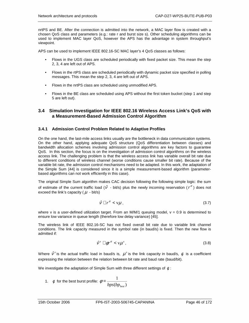
Network architecture and protocols CAP-D27-WP25-BUTE-PUB-P03
15th October 2006 FP6-IST-2003-506745-CAPANINA Page 46 of 172
nrtPS and BE. After the connection is admitted into the network, a MAC layer flow is created with a chosen QoS class and parameters (e.g.: rate r and burst size s). Other scheduling algorithms can be used to implement MAC layer QoS, however the APS has the advantage in system throughput’s viewpoint.
APS can be used to implement IEEE 802.16-SC MAC layer’s 4 QoS classes as follows:
• Flows in the UGS class are scheduled periodically with fixed packet size. This mean the step 2, 3, 4 are left out of APS.
• Flows in the rtPS class are scheduled periodically with dynamic packet size specified in polling messages. This mean the step 2, 3, 4 are left out of APS.
• Flows in the nrtPS class are scheduled using unmodified APS.
• Flows in the BE class are scheduled using APS without the first token bucket (step 1 and step 5 are left out).
3.4 Simulation Investigation for IEEE 802.16 Wirele ss Access Link’s QoS with a Measurement-Based Admission Control Algorithm
3.4.1 Admission Control Problem Related to Adaptive Profiles
On the one hand, the last-mile access links usually are the bottleneck in data communication systems. On the other hand, applying adequate QoS structure (QoS differentiation between classes) and bandwidth allocation schemes involving admission control algorithms are key factors to guarantee QoS. In this section, the focus is on the investigation of admission control algorithms on the wireless access link. The challenging problem is that the wireless access link has variable overall bit rate due to different conditions of wireless channel (worse conditions cause smaller bit rate). Because of the variable bit rate, the admission control mechanisms need to be adapted. In this work, the adaptation of the Simple Sum [44] is considered since it is a simple measurement-based algorithm (parameter-based algorithms can not work efficiently in this case).
The original Simple Sum algorithm makes CAC decision following the following simple logic: the sum
of estimate of the current traffic load (ν̂ - bit/s) plus the newly incoming reservation ( αr ) does not exceed the link’s capacity ( µ - bit/s)
µν α vˆ <+ r , (3.7)
where v is a user-defined utilization target. From an M/M/1 queuing model, v = 0.9 is determined to ensure low variance in queue length (therefore low delay variance) [45].
The wireless link of IEEE 802.16-SC has not fixed overall bit rate due to variable link channel conditions. The link capacity measured in the symbol rate (in baud/s) is fixed. Then the new flow is admitted if:
ss r µφν α vˆ <+ , (3.8)
Where sν̂ is the actual traffic load in baud/s is, sµ is the link capacity in baud/s, φ is a coefficient expressing the relation between the relation between bit rate and baud rate (baud/bit).
We investigate the adaptation of Simple Sum with three different settings of φ :
1. φ for the best burst profile: )(
1
bestbpbps=φ

Network architecture and protocols CAP-D27-WP25-BUTE-PUB-P03
15th October 2006 FP6-IST-2003-506745-CAPANINA Page 47 of 172
2. φ for the worst burst profile: )(
1
worsebpbps=φ
3. φ for the average burst profile: v
v s
ˆ
ˆ=φ
3.4.2 Evaluation
To investigate the performance of the modified Simple Sum algorithm with three different settings of φ , we carried out simulation experiences similar to those of [44]. New flows arrive in Poisson process with inter-arrival time of 0.4 s. The state of flows changes according to the ON-OFF model. In ON state, the flows transmit with fixed bit rate of R, and in OFF state, they do not transmit data. We investigated 5 different source models: in the first two models, the ON and OFF time is exponentially distributed while in remaining three models, they are pareto-distributed. The distribution of the holding time of the flows is also exponential in the first two models and is lognormal in the last three models (Table 6). The measurement interval is 0.1 s. The packet size is 2000 bits for all cases.
Table 6: Parameter setting of simulation.
Arrival Process
Exp Exp Exp Exp Exp
Average inter-arrival time of
flows
0.4 0.4 0.4 0.4 0.4
Holding time process
Exp Exp Lognormal Lognormal Lognormal
Average holding time
300 300 300 300 300
Shape parameter of holding time
N/A N/A 0.3 0.3 0.3
ON/OFF model
Exp Exp Pareto Pareto Pareto
ON average time
0.1 0.01 0.3 0.3 0.03
OFF average time
0.1 0.1 0.3 3 0.3
Transmission rate (bit/s)
128k 512k 128k 600k 512k
The channel state is simulated by a Markov chain described in Section E. APS is used for the packet scheduling. Figure 11 shows the histogram of used capacity: model 1 and model 2 caused more centralized distribution around the capacity limit (0.9*80=72 slots/frame) while models 3-5 cause larger variance.

Network architecture and protocols CAP-D27-WP25-BUTE-PUB-P03
15th October 2006 FP6-IST-2003-506745-CAPANINA Page 48 of 172
Histogram of average assigned slots measured over 0.1s
0.0000
0.0005
0.0010
0.0015
0.0020
0 8 16 24 32 40 48 56 64 72 80 88 96 104
112
120
128
136
144
152
160
Number of assigned slots
model 1 sigmatype min model 1 sigmatype max model 1 sigmatype mes.
model 2 sigmatype min model 2 sigmatype max model 2 sigmatype mes.
(a)
Density function of average assigned slots measured over 0.1s
0.0000
0.0001
0.0002
0.0003
0.0004
0.0005
0.0006
0.0007
0.0008
0 13 26 39 52 65 78 91 104
117
130
143
156
Number of assigned slotsmodel 3 sigmatype min model 3 sigmatype max model 3 sigmatype mes. model 4 sigmatype min model 4 sigmatype max
model 4 sigmatype mes. model 5 sigmatype min model 5 sigmatype max model 5 sigmatype mes.
(b)
Figure 11: Histogram of used capacity (number of as signed slots), (a) for model 1-2 and (b) for model 3-5.
Table 7 shows the statistics of packet loss, link utilization and blocking probability for each model with each settings of φ . As expected in general, the minimum profile setting results in the lowest packet loss rate, lowest link utilization and highest blocking probability for the same source model. On the contrary, the maximum profile setting results in highest loss rate, highest link utilization and lowest blocking probability. The average (mes.) profile setting has results between these two settings. However, for bursty traffic models (3-5), it approaches the low packet loss probability of the minimum
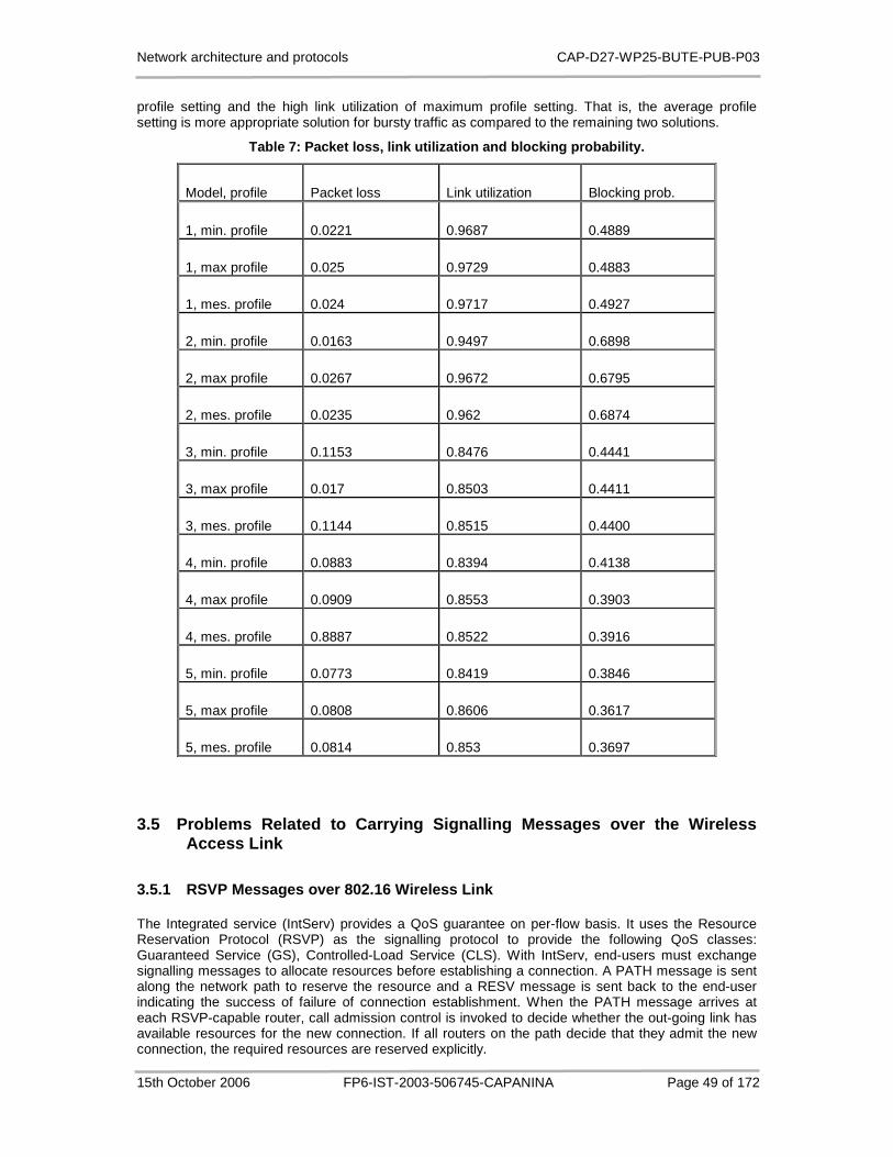
Network architecture and protocols CAP-D27-WP25-BUTE-PUB-P03
15th October 2006 FP6-IST-2003-506745-CAPANINA Page 49 of 172
profile setting and the high link utilization of maximum profile setting. That is, the average profile setting is more appropriate solution for bursty traffic as compared to the remaining two solutions.
Table 7: Packet loss, link utilization and blocking probability.
Model, profile Packet loss Link utilization Blocking prob.
1, min. profile 0.0221 0.9687 0.4889
1, max profile 0.025 0.9729 0.4883
1, mes. profile 0.024 0.9717 0.4927
2, min. profile 0.0163 0.9497 0.6898
2, max profile 0.0267 0.9672 0.6795
2, mes. profile 0.0235 0.962 0.6874
3, min. profile 0.1153 0.8476 0.4441
3, max profile 0.017 0.8503 0.4411
3, mes. profile 0.1144 0.8515 0.4400
4, min. profile 0.0883 0.8394 0.4138
4, max profile 0.0909 0.8553 0.3903
4, mes. profile 0.8887 0.8522 0.3916
5, min. profile 0.0773 0.8419 0.3846
5, max profile 0.0808 0.8606 0.3617
5, mes. profile 0.0814 0.853 0.3697
3.5 Problems Related to Carrying Signalling Message s over the Wireless Access Link
3.5.1 RSVP Messages over 802.16 Wireless Link
The Integrated service (IntServ) provides a QoS guarantee on per-flow basis. It uses the Resource Reservation Protocol (RSVP) as the signalling protocol to provide the following QoS classes: Guaranteed Service (GS), Controlled-Load Service (CLS). With IntServ, end-users must exchange signalling messages to allocate resources before establishing a connection. A PATH message is sent along the network path to reserve the resource and a RESV message is sent back to the end-user indicating the success of failure of connection establishment. When the PATH message arrives at each RSVP-capable router, call admission control is invoked to decide whether the out-going link has available resources for the new connection. If all routers on the path decide that they admit the new connection, the required resources are reserved explicitly.

Network architecture and protocols CAP-D27-WP25-BUTE-PUB-P03
15th October 2006 FP6-IST-2003-506745-CAPANINA Page 50 of 172
At the wireless access link of HAP networks, the situation is a bit different. Besides performing admission control and resource reservation, the base station also needs to establish a LL connection to carry data of the admitted new connection.
HAP
HAP
HAPPATH
RESV
PATHRES
V
DSA.rsp
DSA.req
Gateway
Internet
SenderReceiver
PATH
RESV
RESVPATH
HAP
HAP
HAPPATH
RESV
PATHRES
V
DSA.rsp
DSA.req
Gateway
Internet
SenderReceiver
PATH
RESV
RESVPATH
Figure 12: Mapping for RSVP messages into LL signal ling messages.
Reference [30] proposes 2 different solutions to carry RSVP messages over the 802.16 link and to establish LL connections: (1) The RSVP PATH and RESV messages are transmitted using the Secondary Management connection (Other protocol-specific packets such as Dynamic Host Configuration Protocol (DHCP), Trivial File Transfer Protocol (TFTP), SNMP, etc. are also transmitted through this type of connection) and if the connection is admitted, the LL connection is established afterward by sending the DSA-req message. (2) The RSVP messages are translated directly to the DSA-req messages and the using of Secondary Management connection is not necessary (Figure 12). [30] stated that the later solution is superior in term of speed and efficiency. However, the detail mapping between RSVP PATH message and DSA-req message and the mapping between RSVP RESV message and DSA-rsp have not been considered.
The detailed data fields of DSx (DSA and/ DSC) are described in Appendix A and those of RSVP PATH and RESV messages are given in RFC 2210, RFC 2211 and RFC 2212. The comparison of two sets of parameters leads to the conclusion that not all information packed in the RSVP messages can be delivered by DSx messages. For example, in this section we investigate in details how to map the QoS parameters between RSVP messages and LL signalling messages. Also, the multiplexing of several IntServ connections into a single LL connection is also considered.
Table 8 shows the mapping between TSPEC object in the RSVP PATH and the service flow parameter set. The parameters of the SENDER-ADSPEC have aggregate values (sum, min, max, etc.) of the entire path; therefore, it is not interest from IEEE 802.16’s point of view. We propose to encode the entire SENDER-ADSPEC object into the “Vendor specific QoS parameters” field.
Table 9 describes the mapping of the FLOWSPEC object included in the RSVP RESV message and the service flow parameter set. Note that the service flow parameter set is only included in the DSx.rsp if the relevant DSx transaction is successful. In case o unsuccessful transaction due to there are not enough available resources on the wireless access link or another link on the path, the RSVP RESV can be sent on the Secondary Management connection.
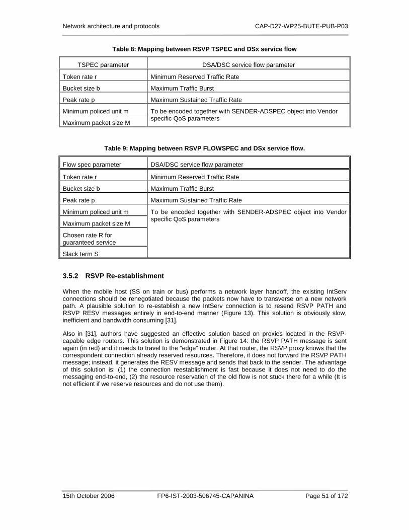
Network architecture and protocols CAP-D27-WP25-BUTE-PUB-P03
15th October 2006 FP6-IST-2003-506745-CAPANINA Page 51 of 172
Table 8: Mapping between RSVP TSPEC and DSx service flow
TSPEC parameter DSA/DSC service flow parameter
Token rate r Minimum Reserved Traffic Rate
Bucket size b Maximum Traffic Burst
Peak rate p Maximum Sustained Traffic Rate
Minimum policed unit m
Maximum packet size M
To be encoded together with SENDER-ADSPEC object into Vendor specific QoS parameters
Table 9: Mapping between RSVP FLOWSPEC and DSx serv ice flow.
Flow spec parameter DSA/DSC service flow parameter
Token rate r Minimum Reserved Traffic Rate
Bucket size b Maximum Traffic Burst
Peak rate p Maximum Sustained Traffic Rate
Minimum policed unit m
Maximum packet size M
Chosen rate R for guaranteed service
Slack term S
To be encoded together with SENDER-ADSPEC object into Vendor specific QoS parameters
3.5.2 RSVP Re-establishment
When the mobile host (SS on train or bus) performs a network layer handoff, the existing IntServ connections should be renegotiated because the packets now have to transverse on a new network path. A plausible solution to re-establish a new IntServ connection is to resend RSVP PATH and RSVP RESV messages entirely in end-to-end manner (Figure 13). This solution is obviously slow, inefficient and bandwidth consuming [31].
Also in [31], authors have suggested an effective solution based on proxies located in the RSVP-capable edge routers. This solution is demonstrated in Figure 14: the RSVP PATH message is sent again (in red) and it needs to travel to the “edge” router. At that router, the RSVP proxy knows that the correspondent connection already reserved resources. Therefore, it does not forward the RSVP PATH message; instead, it generates the RESV message and sends that back to the sender. The advantage of this solution is: (1) the connection reestablishment is fast because it does not need to do the messaging end-to-end, (2) the resource reservation of the old flow is not stuck there for a while (It is not efficient if we reserve resources and do not use them).

Network architecture and protocols CAP-D27-WP25-BUTE-PUB-P03
15th October 2006 FP6-IST-2003-506745-CAPANINA Page 52 of 172
Figure 13: Re-establish the IntServ connection by s ending RSVP PATH and RESV again.
Figure 14: Using RSVP proxy.
Reference [31] suggests that the RSVP proxy should be implemented at the “edge” router, which is located after the access routers and at the edge of the core network. This recommendation is based on the technical terms of Mobile IP.
Applying this proxy solution in CAPANINA HAP network reveal a question: where to locate the proxy? Additional characteristics of HAP networks should be taken into account to answer this question.
We can discuss the following options:
1. RSVP proxy on the HAP, at the wireless access link
2. RSVP proxy on the HAP, at the inter-platform link.
3. RSVP proxy on the HAP, at the backhaul link.
4. RSVP proxy on the gateway, on the ground.

Network architecture and protocols CAP-D27-WP25-BUTE-PUB-P03
15th October 2006 FP6-IST-2003-506745-CAPANINA Page 53 of 172
Option (1) obviously is not necessary because the network-layer hand-off often means the change of access router (access HAP); therefore; the access HAP can not be in the common path of the old route and new route.
Option (2) is necessary if the corresponding HAP can be on the common path. This occur only if we have a big HAP cloud (containing lots of HAP) and packets have to travel over more than 1 inter-platform link before arriving to the back-haul link.
Generally, Option (3) is necessary because the back-haul link is the bottleneck of the system. Locating a proxy here prevent the unnecessary resource reservation on the backhaul link.
Similarly, Option (4) is necessary at any bottleneck link on the ground.
3.6 Combining DiffServ, ToS Routing and MPLS to Sup port QoS
From the description of MPLS characteristics it has become clear that the particular challenge for employing MPLS networking in a HAP network is the potential dynamics of the platforms. Although, we can consider HAPs as semi-fixed nodes and the network topology can be regarded as almost permanent, there are still inherent and frequent handovers between ground users/stations and serving HAPs which have to be taken into account.
Let us consider such ground users, collective terminals or stations simply as MPLS routers from a networking perspective. The fact that regular and frequent handovers appear between network nodes (routers) is strongly related to the question where to set the boundaries of the MPLS network properly. There are two possibilities shown in Figure 15.
As a first option, those HAPs serving ground (depending on the position of the platforms, i.e., effectively all HAPs unless some are positioned over deserted areas) could be considered as LERs; this would restrict the MPLS backbone network completely to the “sky” network, which has an almost permanent topology and could thus, on principle, be operated without stringent LSP rerouting requirements (see Figure 15.a). However, this solution has some serious drawbacks: LERs, as already explained, constitute in a way the intelligence of the network, they manage the label distribution and, in some cases, perform route computations. So placing the LERs “in the sky” means notable on-board processing.
As a second option, leaving the HAPs as simple LSRs to avoid such on-board processing, we must place the LERs (and the network boundaries) on ground. This causes the earth-HAP link to fall inside the MPLS network (see Figure 15.b). This first link becomes very critical for the operation of any LSP using it, since the link might be involved in frequent handovers and this implies continuous rerouting decisions and computations for the LSP.
It should be noted, however, that rerouting has to be performed in both cases — either if the LERs are placed on board or if they are placed on ground, respectively — as end-to-end traffic always flows from ground to ground, but there is a conceptual difference: In the former case of HAPs as LERs, the ground station may trigger a systematic handover from an old to a new serving HAP (LER) by asking to tear down the active LSP (from the old HAP) and sending a new LSP setup request to the new HAP; consequently, a new phase of LSP activation begins with its related QoS negotiation and its admission control. In the latter case, when the LERs are placed on ground, approaching a handover they can ask for a rerouting computation, but there is no QoS negotiation, nor an admission decision: the LSP was already active and its attributes are already known, so, if possible, it has to be maintained with the same characteristics.
In conclusion, there are no worthwhile advantages to implement LER functionalities on board. Rather two advantages of having LERs placed on ground are dominating: first, there is no need to restart a QoS negotiation or admission control for rerouting of an LSP due to HAP handover; second, expensive and complex on-board processing for advanced routing functionality is avoided. So the second solution, depicted in Figure 15.b, should be preferred.

Network architecture and protocols CAP-D27-WP25-BUTE-PUB-P03
15th October 2006 FP6-IST-2003-506745-CAPANINA Page 54 of 172
LER 1LER 2
LER 3
HAP
HAPHAP
HAP
LER 1 LER 2 LER 3
HAP
HAPHAP
HAP
(a) (b)
Figure 15: MPLS deployment over a HAP network.
Since MPLS gives many possibilities to perform traffic engineering and to provide QoS, we need to address them in a clear way in order to analyse which is the most suitable for the application to a HAP-meshed network. For this reason in the following we will explore two main techniques (DiffServ and Type-of-Service routing) and we will see how they affect MPLS characteristics and how they can be combined in order to get good QoS performance in a HAP network.
The purpose of this section is to investigate the use of three main techniques: DiffServ, ToS routing and MPLS, in different combinations with each other to distinguish flows belonging to different traffic classes and treat them accordingly.
Behind the particularities of each of these approaches resides a common idea: how queues in output links and related link-costs can play a role in the forwarding and routing paradigms, especially when considering a QoS context. In the light of this, we will investigate six approaches:
1. DiffServ approach.
2. DiffServ over MPLS approach.
3. ToS Routing approach.
4. ToS Routing over MPLS approach.
5. DiffServ and ToS Routing over MPLS approach.
6. DiffServ over Tos Routing approach.
They present different strategies with regards to forwarding and routing and different ways to exploit queues and link-cost metrics. We will present some simulation results comparing these six approaches. The aim is to find out how effective each approach is when dealing with different levels of services. The effectiveness is evaluated in terms of average throughput and end-to-end delay experienced by each traffic class and also in terms of network resources utilization. We will assume to have three different service classes, A, B and C, ranked by priority order. The assumption of three traffic classes is motivated by three traffic classes of DiffServ: Expedited Forwarding, Assured Forwarding and Best-Effort. Even in link layer (LL), we have 4 QoS shown in Table 1, the QoS class A, B and C can be mapped to LL’s 4 QoS classes as shown in Appendix C.
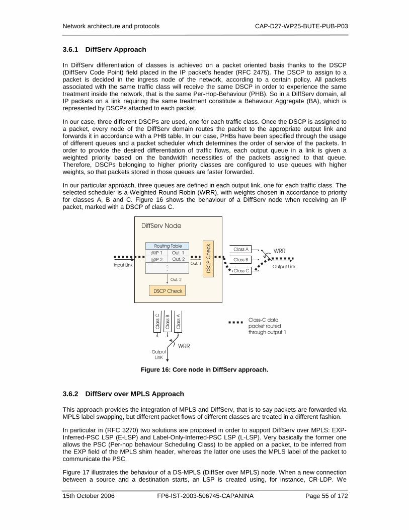
Network architecture and protocols CAP-D27-WP25-BUTE-PUB-P03
15th October 2006 FP6-IST-2003-506745-CAPANINA Page 55 of 172
3.6.1 DiffServ Approach
In DiffServ differentiation of classes is achieved on a packet oriented basis thanks to the DSCP (DiffServ Code Point) field placed in the IP packet's header (RFC 2475). The DSCP to assign to a packet is decided in the ingress node of the network, according to a certain policy. All packets associated with the same traffic class will receive the same DSCP in order to experience the same treatment inside the network, that is the same Per-Hop-Behaviour (PHB). So in a DiffServ domain, all IP packets on a link requiring the same treatment constitute a Behaviour Aggregate (BA), which is represented by DSCPs attached to each packet.
In our case, three different DSCPs are used, one for each traffic class. Once the DSCP is assigned to a packet, every node of the DiffServ domain routes the packet to the appropriate output link and forwards it in accordance with a PHB table. In our case, PHBs have been specified through the usage of different queues and a packet scheduler which determines the order of service of the packets. In order to provide the desired differentiation of traffic flows, each output queue in a link is given a weighted priority based on the bandwidth necessities of the packets assigned to that queue. Therefore, DSCPs belonging to higher priority classes are configured to use queues with higher weights, so that packets stored in those queues are faster forwarded.
In our particular approach, three queues are defined in each output link, one for each traffic class. The selected scheduler is a Weighted Round Robin (WRR), with weights chosen in accordance to priority for classes A, B and C. Figure 16 shows the behaviour of a DiffServ node when receiving an IP packet, marked with a DSCP of class C.
DSCP Check
DSC
P C
he
ckRouting Table
...
Class A
Class B
Class C
Cla
ss A
Cla
ss B
Cla
ssC
DiffServ Node
Output LinkInput Link
WRR
Output
LinK
WRR
Out. 1
Out. 2
@IP 1
@IP 2Out. 1
Out. 2
Class-C data
packet routed
through output 1
Figure 16: Core node in DiffServ approach.
3.6.2 DiffServ over MPLS Approach
This approach provides the integration of MPLS and DiffServ, that is to say packets are forwarded via MPLS label swapping, but different packet flows of different classes are treated in a different fashion.
In particular in (RFC 3270) two solutions are proposed in order to support DiffServ over MPLS: EXP-Inferred-PSC LSP (E-LSP) and Label-Only-Inferred-PSC LSP (L-LSP). Very basically the former one allows the PSC (Per-hop behaviour Scheduling Class) to be applied on a packet, to be inferred from the EXP field of the MPLS shim header, whereas the latter one uses the MPLS label of the packet to communicate the PSC.
Figure 17 illustrates the behaviour of a DS-MPLS (DiffSer over MPLS) node. When a new connection between a source and a destination starts, an LSP is created using, for instance, CR-LDP. We

Network architecture and protocols CAP-D27-WP25-BUTE-PUB-P03
15th October 2006 FP6-IST-2003-506745-CAPANINA Page 56 of 172
assumed that in the picture there are three traffic classes with decreasing priorities, and we assumed that LDP packets are considered with high priority, so as if they belong to class A. During the LSP establishment process, an MPLS node receiving an LDP packet performs essentially three actions:
1. Determine the output link according to the routing table;
2. Retrieve information on which per-hop behaviour (PHB) the advertised label is to be bound;
3. Actualize the data related to the being-created LSP (in/out labels and in/out interfaces) in the label switching table.
The LDP packet is then forwarded to the next node to continue creating the LSP. Later, when MPLS data packets arrive, the information stored in the label forwarding table will be used for switching/forwarding purposes. In Figure 17, three different queues are defined in each output link of the MPLS network to support the three desired traffic classes. The three queues may be managed with a weighted round robin (WRR) scheduler, for example, to accomplish the different priorities.
From a functional point of view, this approach only differs from a simple DiffServ one, in its connection-oriented fashion as opposed to the connectionless property of DiffServ.
Routing Table
...
Class A
Class B
Class C
Cla
ss A
Cla
s s B
Cla
ss C
MPLS+ DiffServ Node
Output Link
Input Link
WRR
OutputLinK
WRR
Out. 1Out. 2
@IP 1
@IP 2Out. 1
LDP messageto setup LSP for Class-Cdata packets
LSP for Class-Cdata packetsthrough output 1
...
Label Switching Table
IN Int./Label
...
OUT Int./Label
Service Class.
Out. 2
Serv
ice
Cla
ss.
Figure 17: Core node in DiffServ-over-MPLS approach .
3.6.3 ToS Routing Approach
Type-of-Service (ToS) Routing provides traffic class differentiation by using a special adaptive routing strategy for each class. By adaptive routing strategy we mean that each class (described by the “TOS field” of the IP header) has its own particular traffic-adaptive metric to compute routes inside the network. In other words, the cost of going from one node to another, which is used afterwards to select the routes, is calculated differently depending on the present traffic conditions and on the traffic class. As a consequence, different traffic classes can be routed over different paths according to these optimization criteria. So a way to bring QoS in the routing is to calculate link costs using parameters related to the status of the network (see RFC 2386, RFC 2676).
In the following we present a simple way to introduce an adaptive measure of the link congestion in the routing metrics and to calculate class-based routing tables to forward data packets belonging to different traffic classes. As it is said in (RFC 2386), two aspect have to be considered in adaptive, network state dependent routing: (i) measuring and gathering of the network state information; (ii)
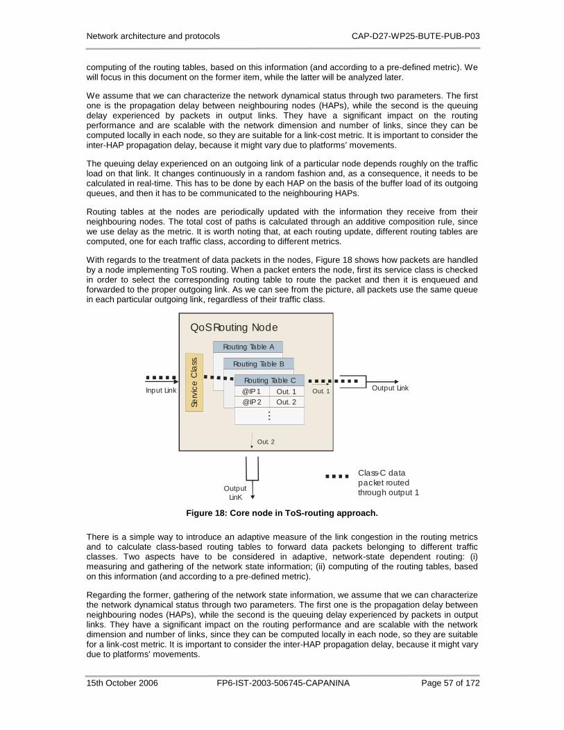
Network architecture and protocols CAP-D27-WP25-BUTE-PUB-P03
15th October 2006 FP6-IST-2003-506745-CAPANINA Page 57 of 172
computing of the routing tables, based on this information (and according to a pre-defined metric). We will focus in this document on the former item, while the latter will be analyzed later.
We assume that we can characterize the network dynamical status through two parameters. The first one is the propagation delay between neighbouring nodes (HAPs), while the second is the queuing delay experienced by packets in output links. They have a significant impact on the routing performance and are scalable with the network dimension and number of links, since they can be computed locally in each node, so they are suitable for a link-cost metric. It is important to consider the inter-HAP propagation delay, because it might vary due to platforms’ movements.
The queuing delay experienced on an outgoing link of a particular node depends roughly on the traffic load on that link. It changes continuously in a random fashion and, as a consequence, it needs to be calculated in real-time. This has to be done by each HAP on the basis of the buffer load of its outgoing queues, and then it has to be communicated to the neighbouring HAPs.
Routing tables at the nodes are periodically updated with the information they receive from their neighbouring nodes. The total cost of paths is calculated through an additive composition rule, since we use delay as the metric. It is worth noting that, at each routing update, different routing tables are computed, one for each traffic class, according to different metrics.
With regards to the treatment of data packets in the nodes, Figure 18 shows how packets are handled by a node implementing ToS routing. When a packet enters the node, first its service class is checked in order to select the corresponding routing table to route the packet and then it is enqueued and forwarded to the proper outgoing link. As we can see from the picture, all packets use the same queue in each particular outgoing link, regardless of their traffic class.
Serv
ice
Cla
ss.
QoS Routing Node
Output LinkInput Link
OutputLinK
Out. 1
Out. 2
Class-C data packet routedthrough output 1
Routing Table C
...
Out. 1Out. 2
@IP 1
@IP 2
Routing Table A
Routing Table B
@IP 2@IP 1 Out. 1
Out. 2
Figure 18: Core node in ToS-routing approach.
There is a simple way to introduce an adaptive measure of the link congestion in the routing metrics and to calculate class-based routing tables to forward data packets belonging to different traffic classes. Two aspects have to be considered in adaptive, network-state dependent routing: (i) measuring and gathering of the network state information; (ii) computing of the routing tables, based on this information (and according to a pre-defined metric).
Regarding the former, gathering of the network state information, we assume that we can characterize the network dynamical status through two parameters. The first one is the propagation delay between neighbouring nodes (HAPs), while the second is the queuing delay experienced by packets in output links. They have a significant impact on the routing performance and are scalable with the network dimension and number of links, since they can be computed locally in each node, so they are suitable for a link-cost metric. It is important to consider the inter-HAP propagation delay, because it might vary due to platforms’ movements.

Network architecture and protocols CAP-D27-WP25-BUTE-PUB-P03
15th October 2006 FP6-IST-2003-506745-CAPANINA Page 58 of 172
The queuing delay experienced on an outgoing link of a particular node depends roughly on the traffic load on that link. It changes continuously in a random fashion and, as a consequence, it needs to be calculated in real-time. This has to be done by each HAP on the basis of the buffer load of its outgoing queues, and then it has to be communicated to the neighbouring HAPs.
This information can be distributed by means of traditional routing signalling protocols, the way to do it will differ according to the selected routing algorithm (link state or distance vector algorithms). We will assume for our simulations to have a distance-vector algorithm, because this allows a really distributed routing system, which looks more suitable for a HAP-meshed network where new platforms may be added and removed without having to re-configure the routing. However the way routing signalling is performed does not have a relevant impact on the resulting QoS performance.
We will present in the following a simple routing metric, which can be considered just as an example. It is a function of the two above mentioned parameters (propagation delay and queuing delay) and it was used in the simulations which will be presented later. Thus it represents a particular implementation of a dynamic ToS routing, but it serves as a reference in the comparison with the other approaches.
In the current implementation we have assumed ipd , to be the propagation delay between node pairs,
where i denotes the link number as being constant and equal for all links. Therefore, in the following we consider: Pip dd =, , i∀ . The queuing delay iqd , experienced by a packet on an outgoing link i of
a particular node depends roughly on the traffic load on that link. We define an estimation of the queuing delay iQd , as a measure of the real iqd , . This value will be considered in the link-cost
function of the outgoing link i and it is periodically computed through an estimation of the queue size in the link ( iQS , ). To calculate )(, tS iQ at time t, we use not only the current value of the queue size
( )(, tS iq ) but also the last of the computed estimations )1(, −tS iQ . As shown in the next equation, a
forgetting factor [ ]1;0∈χ is introduced to make the recent queuing size value ( )(, tS iq ) more
significant than the previous ones:
)()1()1()( ,,, tStStS iqiQiQ χχ +−−=
(3.9)
Then, the estimated queuing delay can be calculated as iiQiQ CtStd /)()( ,, = , where iC is the
capacity of the link i.
Finally, the following equation represents the normalized changing link cost metric im according to
variation of propagation and queuing delay:
offMAXiQP
iQPoffi dd
ddm δδ
α
+
++
−=,,
,)1( (3.10)
MAXiQd ,, is the maximum possible queuing delay the packets can experience and it depends on the
maximum queue size, which is the same for all links. With the intention not to cause high oscillations in the routing algorithm, and too frequent exchange of routing signalling information, only variations in queuing delays higher than 0.1 s trigger routing updates. If MAXiQd ,, = 2 s, this means that the routing
metric is only updated when the queuing delay in one link varies more than 5% of the maximum queuing delay in a link.
In order to be able to control the relative cost of heavily loaded links (links with high queuing delay) with respect to slightly loaded links (links with low queuing delay), we have introduced an exponential factorα , converting the equation into a non-linear link-cost function. Besides, a small offset offδ is
added to avoid instability in the routing, when the link cost goes to zero.

Network architecture and protocols CAP-D27-WP25-BUTE-PUB-P03
15th October 2006 FP6-IST-2003-506745-CAPANINA Page 59 of 172
In accordance to the delay requirements of each traffic class, we have chosen α = 4 for class A, α = 10 for class B and α = 0 for class C. The offset for the first two classes has been set to 0.2 and for class C, to 0. In Figure 19 the link-cost functions for these selected values are plotted. As it is appreciable from the picture, class A penalizes links with high queuing delay, which means that as soon as the delay experienced by packets in a particular path starts growing due to queuing delay, the cost of this route for traffic class A increases significantly and, as a consequence, the route becomes too costly to be used. On the other hand, link-cost for class B has a more permissive cost policy because for low and medium queuing delays it maintains a constant value for the cost, which only increases for high queuing delays. Finally, for best effort class (class C), with no special requirements regarding delay, a constant link-cost function is used. As a consequence, packets belonging to class C always follow those routes with minimum number of hops, even if links in those paths are the more congested ones.
0 0.05 0.1 0.15 0.2 0.25 0.3 0.35 0.40
0.2
0.4
0.6
0.8
1
Queuing Delay [s]
Link
Cos
t
Class CClass BClass A
Figure 19: Link-Cost functions for the different tr affic classes in ToS routing approach.
Regarding the latter point, computing of the routing tables, route computation can be done at the nodes in a decentralized way. The total cost of paths is calculated through an additive composition rule, since we use delay as the metric. Routing tables at the nodes are periodically updated with the information they receive from their neighbouring nodes, since, as we previously said, distance vector routing is assumed and Bellman-Ford algorithm can be used to find minimum-cost routes. It is worth noting that, at the end of each route update interval, three different routing tables are computed, one for each traffic class.
3.6.4 ToS Routing over MPLS Approach
In this approach, ToS routing is used to monitor the network status and to compute the routing tables at each node, while MPLS uses this routing information to establish LSPs every time a new connection is created. In this case, current network traffic conditions are only considered at the establishment of the LSPs, because routing tables are bypassed by MPLS-labelled packets, since they are label-switched. That is, if routing tables are modified due to changes in the network status, while a flow is running, packets belonging to this flow will always follow the same route, which was the best one at the time of its creation, according to the available routing information at that time.
This particular behaviour is depicted in Figure 20.
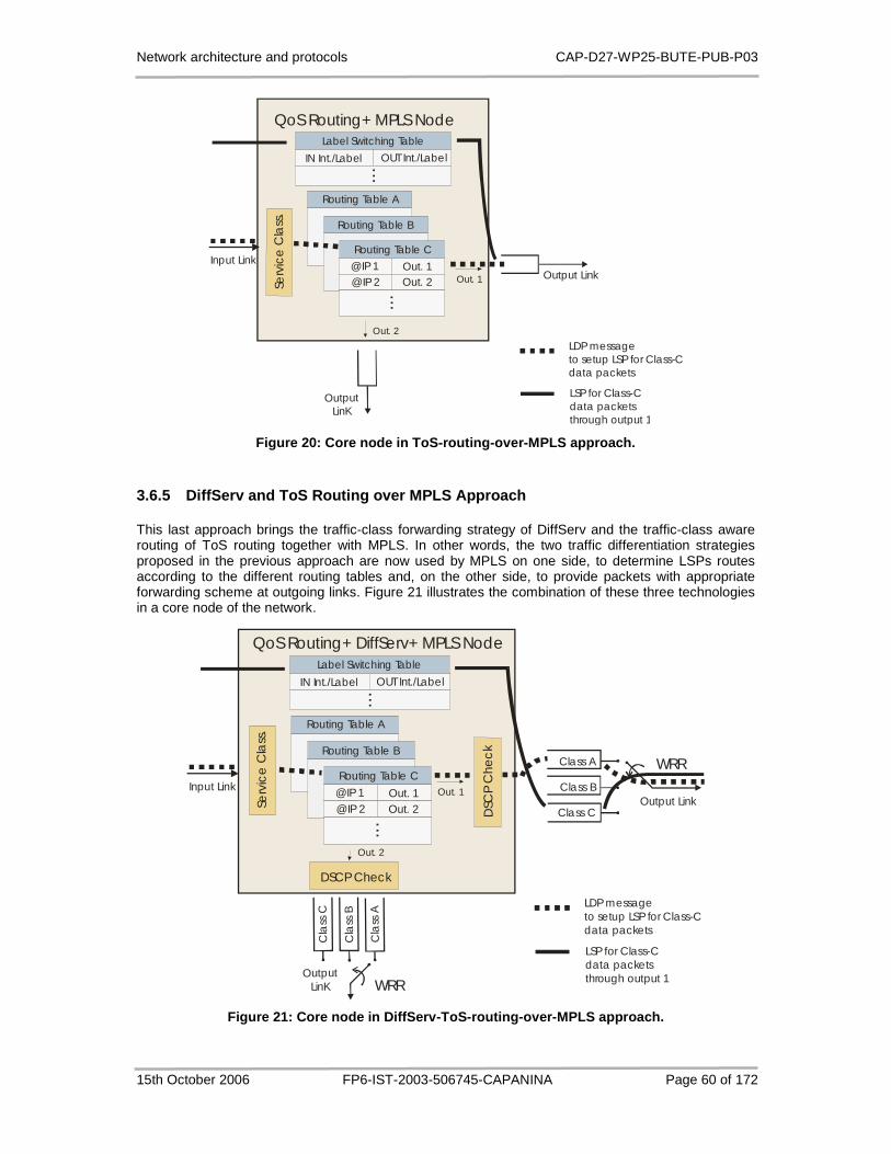
Network architecture and protocols CAP-D27-WP25-BUTE-PUB-P03
15th October 2006 FP6-IST-2003-506745-CAPANINA Page 60 of 172
Serv
ice
Cla
ss.
QoS Routing+ MPLS Node
Output LinkInput Link
OutputLinK
Out. 1
@IP 1
@IP 2
Out. 2
Routing Table C
...
Routing Table A
Routing Table B
@IP 2@IP 1 Out. 1
Out. 2
Label Switching Table
IN Int./Label
...
OUT Int./Label
LDP messageto setup LSP for Class-Cdata packets
LSP for Class-Cdata packetsthrough output 1
Figure 20: Core node in ToS-routing-over-MPLS appro ach.
3.6.5 DiffServ and ToS Routing over MPLS Approach
This last approach brings the traffic-class forwarding strategy of DiffServ and the traffic-class aware routing of ToS routing together with MPLS. In other words, the two traffic differentiation strategies proposed in the previous approach are now used by MPLS on one side, to determine LSPs routes according to the different routing tables and, on the other side, to provide packets with appropriate forwarding scheme at outgoing links. Figure 21 illustrates the combination of these three technologies in a core node of the network.
Serv
ice
Cla
ss.
Class A
Class B
Class C
Cla
ss A
Cla
ss B
Cla
ss C
QoS Routing+ DiffServ+ MPLS Node
Output LinkInput Link
WRR
OutputLinK WRR
Out. 1
Out. 2
Routing Table C
...
Out. 2@IP 2
Routing Table A
Routing Table B
@IP 2@IP 1 Out. 1
Out. 2
DSCP Check
DSC
P C
hec
k
Label Switching Table
IN Int./Label
...
OUT Int./Label
LDP messageto setup LSP for Class-Cdata packets
LSP for Class-Cdata packetsthrough output 1
Figure 21: Core node in DiffServ-ToS-routing-over-M PLS approach.
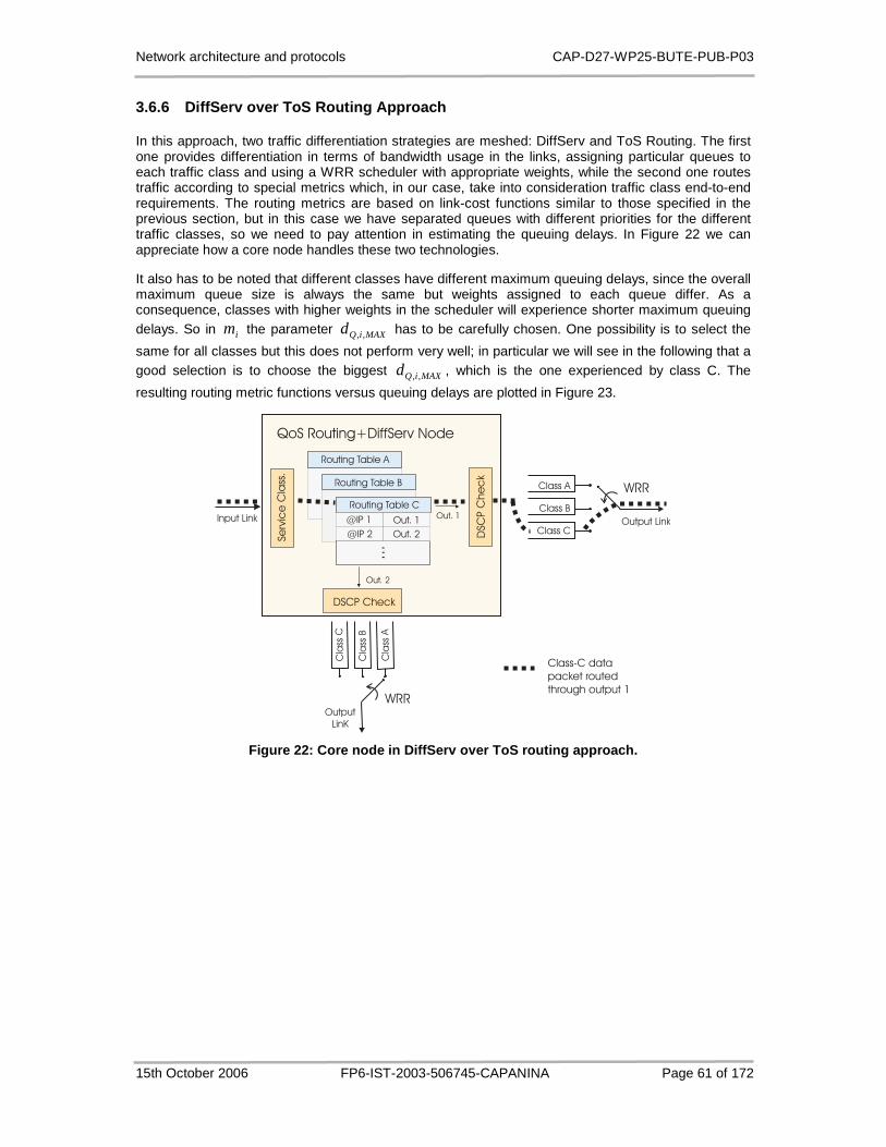
Network architecture and protocols CAP-D27-WP25-BUTE-PUB-P03
15th October 2006 FP6-IST-2003-506745-CAPANINA Page 61 of 172
3.6.6 DiffServ over ToS Routing Approach
In this approach, two traffic differentiation strategies are meshed: DiffServ and ToS Routing. The first one provides differentiation in terms of bandwidth usage in the links, assigning particular queues to each traffic class and using a WRR scheduler with appropriate weights, while the second one routes traffic according to special metrics which, in our case, take into consideration traffic class end-to-end requirements. The routing metrics are based on link-cost functions similar to those specified in the previous section, but in this case we have separated queues with different priorities for the different traffic classes, so we need to pay attention in estimating the queuing delays. In Figure 22 we can appreciate how a core node handles these two technologies.
It also has to be noted that different classes have different maximum queuing delays, since the overall maximum queue size is always the same but weights assigned to each queue differ. As a consequence, classes with higher weights in the scheduler will experience shorter maximum queuing delays. So in im the parameter MAXiQd ,, has to be carefully chosen. One possibility is to select the
same for all classes but this does not perform very well; in particular we will see in the following that a good selection is to choose the biggest MAXiQd ,, , which is the one experienced by class C. The
resulting routing metric functions versus queuing delays are plotted in Figure 23.
Se
rvic
e C
lass
.
Class A
Class B
Class C
Cla
ssA
Cla
ssB
Cla
ss C
QoS Routing+DiffServ Node
Output LinkInput Link
WRR
Output
LinK
WRR
Out. 1
Out. 2
Class-C data
packet routed
through output 1
Routing Table C
...
Out. 1
Out. 2
@IP 1
@IP 2
Routing Table A
Routing Table B
@IP 2
@IP 1 Out. 1
Out. 2
DSCP Check
DSC
P C
he
ck
Figure 22: Core node in DiffServ over ToS routing a pproach.

Network architecture and protocols CAP-D27-WP25-BUTE-PUB-P03
15th October 2006 FP6-IST-2003-506745-CAPANINA Page 62 of 172
0 0.5 1 1.5 20
0.2
0.4
0.6
0.8
1
Queuing Delay [s]
Link
Cos
tClass CClass BClass A
0.2 0.4 0.6 0.8 1 1.2
0.2
0.21
0.22
0.23
Queuing Delay [s]
Link
Cos
t
(a) (b) Zoom
Figure 23: Link cost functions for the different tr affic classes in the DiffServ over ToS routing approach.
3.6.7 Simulations and Performance Evaluation
The above described approaches have been simulated by means of the ns2 software [20], with the usage of the DiffServ module, the MNS (MPLS Network Simulator) package [46], with some changes in order to support DiffServ, and some functionality related to unicast routing. This last aspect required the development of a new routing module with a special packet classifier and the modification of the distance vector protocol, in order to enable a routing based not only on packets' destination but also on the traffic class.
Three traffic classes A, B, C in descending priority order, have been considered. Class A may be representative of real time services (e.g., voice), class B jitter-sensitive non-real-time services (e.g., streaming) and class C best effort applications (e.g., web, email).
The traffic has been generated in the network between a number p of source-destination pairs according to a Poisson process. We will call λ the connection arrival rate at each source-destination pair and µ the connection release rate. Within each connection, a constant bit rate (CBR)
transmission is initiated, using UDP as the transport layer protocol. It is worth noting that the value µλ
results in the average number of simultaneous active connections between each source-destination
pair [47]. So the overall average number of active connections in the case-study network is µλ
p .
Results presented in this section intend to reflect the grade of effectiveness of the different approaches in providing a good balance between delay and bandwidth requirements for the different traffic classes, as well as in optimizing network resources. Several simulations have been carried out for different traffic input loads. The variable used to control network load is λ , while the rest of the parameters are kept fixed.

Network architecture and protocols CAP-D27-WP25-BUTE-PUB-P03
15th October 2006 FP6-IST-2003-506745-CAPANINA Page 63 of 172
3.6.7.1 End-to-end Delay and Throughput Analysis
The delay-throughput compromise kept by each approach when treating the different traffic classes gives an idea about the goodness not only of the routing [48] but also of the forwarding algorithms. That is to say, the better the routing and forwarding schemes, the lower the end-to-end packet delay maintained for any given throughput. Each point in the graphs of Figure 24 corresponds to the average end-to-end delay and throughput experienced by packets of each class given a certain λ .
A first appreciable result is that, within all approaches where DiffServ is used, a very good differentiation of classes is achieved. This can be observed in the fact that traffic class A is always the one acquiring a lower curve end-to-end delay-throughput, followed by class B and, finally, class C. This means that, in these approaches and given any traffic load, packets with higher demands on delay and throughput, i.e. class A and, in a lower degree, class B packets, receive a better treatment inside the core network than the others. This proper differentiation is due to the usage of a WRR scheduler in output links, which guarantees a minimum bandwidth to each traffic class in accordance to their respective requirements.
In the ToS routing and ToS routing over MPLS approaches on the other hand (Figure 24.c and Figure 24.d), the use of an adaptive routing for classes A and B does not only bring benefits to packets of these classes but also to the class-C ones, because as soon as new paths are used for the former two classes, the “old” routes become less crowded. While this situation improves the overall traffic performance, it is not desirable for traffic differentiation purposes, since the three classes experience basically the same performance. This suggests that different routing metrics should be studied for this purpose.
When comparing results between approaches, we can see that the introduction of MPLS in the DiffServ domain (Figure 24.a and Figure 24.b) does not bring any significant difference. This is because in our Poisson input traffic the network is loaded with packets which are already structured in flows or connections. Therefore, the conversion of a packet oriented network into a connection oriented one, thanks to MPLS, does not have a major impact on the results. Furthermore, the other main advantage of MPLS, which is a fast layer-2 switching, can not be appreciated due to the fact that the ns2 software was not configured to simulate that. In practice, however, the reduction on end-to-end delay should be perceived in all traffic classes. In any case, these results prove the interworking capability of MPLS and DiffServ.
On the other hand, the usage of a class-aware routing in the ToS routing and DiffServ over ToS routing approaches (Figure 24.c and Figure 24.d) results in a global network performance improvement, which is specially reflected on the achievement of very low end-to-end delays for all traffic classes. Besides, the inclusion of a forwarding mechanism which takes into account the bandwidth requirements of the different classes, as DiffServ does, helps in providing a proper differentiation in terms of throughput while maintaining a fairly low end-to-end delay thanks to the ToS routing.
The conversion of the two last approaches into connection-oriented networks thanks to MPLS, on the other hand, brings no benefits to the end-to-end delay-throughput performance, as appreciable from Figure 24.d and Figure 24.f. This is due to the fact that routes are decided at the beginning of each connection and not in a packet-by-packet basis. As a consequence, part of the potential of ToS routing, which is maintaining updated routing tables in accordance to the status of the network, is lost because traffic conditions can change during the flow life, so that the already established routes are not the best ones any more.

Network architecture and protocols CAP-D27-WP25-BUTE-PUB-P03
15th October 2006 FP6-IST-2003-506745-CAPANINA Page 64 of 172
(a) DiffServ approach. (b) DiffServ over MPLS ap proach.
(c) ToS Routing approach. (d) ToS Routing over M PLS approach.
(e) DiffServ over ToS Routing approach. (f) DiffSer v and ToS Routing over MPLS.
Figure 24: End-to-end delay-throughput curves.
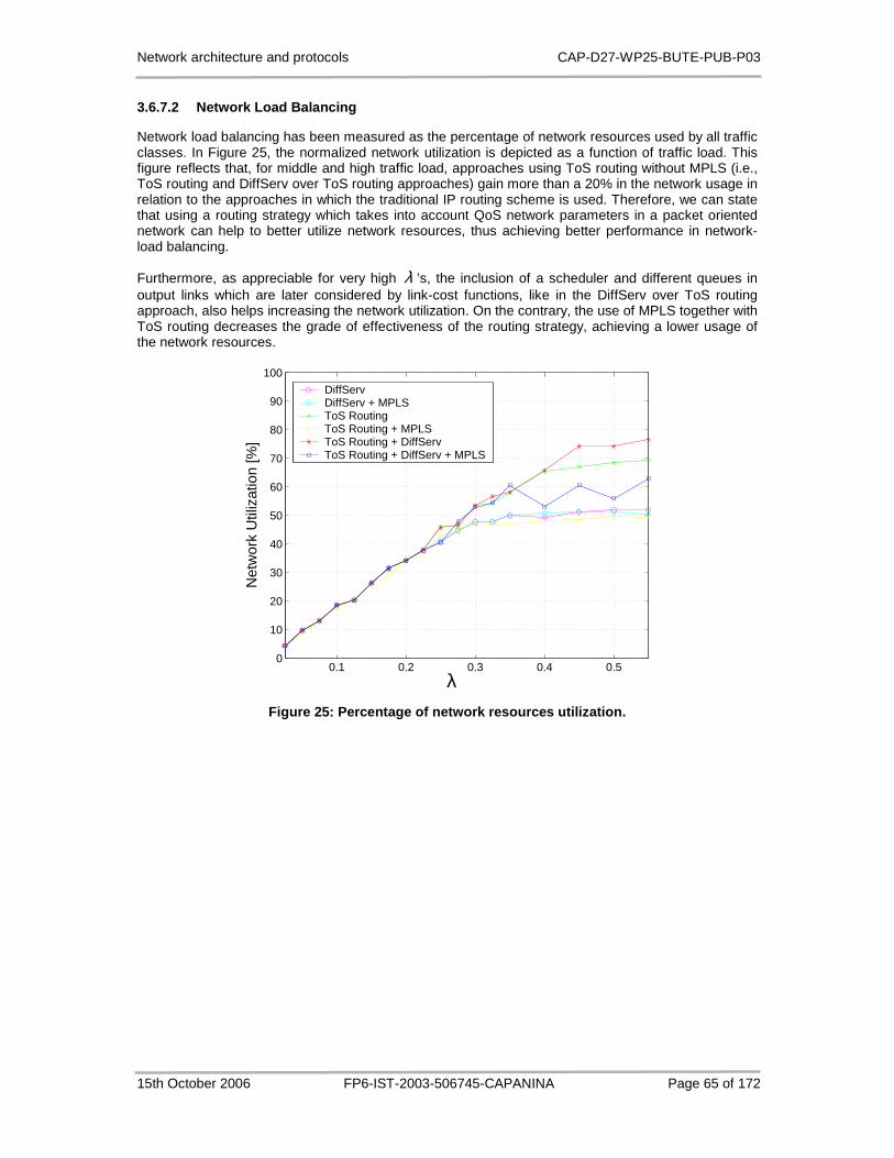
Network architecture and protocols CAP-D27-WP25-BUTE-PUB-P03
15th October 2006 FP6-IST-2003-506745-CAPANINA Page 65 of 172
3.6.7.2 Network Load Balancing
Network load balancing has been measured as the percentage of network resources used by all traffic classes. In Figure 25, the normalized network utilization is depicted as a function of traffic load. This figure reflects that, for middle and high traffic load, approaches using ToS routing without MPLS (i.e., ToS routing and DiffServ over ToS routing approaches) gain more than a 20% in the network usage in relation to the approaches in which the traditional IP routing scheme is used. Therefore, we can state that using a routing strategy which takes into account QoS network parameters in a packet oriented network can help to better utilize network resources, thus achieving better performance in network-load balancing.
Furthermore, as appreciable for very high λ ’s, the inclusion of a scheduler and different queues in output links which are later considered by link-cost functions, like in the DiffServ over ToS routing approach, also helps increasing the network utilization. On the contrary, the use of MPLS together with ToS routing decreases the grade of effectiveness of the routing strategy, achieving a lower usage of the network resources.
0.1 0.2 0.3 0.4 0.50
10
20
30
40
50
60
70
80
90
100
λ
Net
wor
k U
tiliz
atio
n [%
]
DiffServDiffServ + MPLSToS RoutingToS Routing + MPLSToS Routing + DiffServToS Routing + DiffServ + MPLS
Figure 25: Percentage of network resources utilizat ion.
Network architecture and protocols CAP-D27-WP25-BUTE-PUB-P03
15th October 2006 FP6-IST-2003-506745-CAPANINA Page 66 of 172
3.7 Summary
This chapter presents solutions for different open questions and problems related to provision of QoS for CAPANINA HAP networks.
Firstly, we proposed a packet scheduling algorithm called the APS to be used at the IEEE 802.16 wireless access links of CAPANINA HAP networks. Utilizing the different channel conditions seen by subscriber stations, the APS improves the system performance by up to 21% in a normal configuration parameter setting while preserves the long-term fairness and guarantees minimum rates.
Secondly, the using of burst profiles in IEEE 802.16 access technology results in variable overall bit rate of the wireless link. This required some modifications in admission control algorithms developed originally for wired networks. In this work, we proposed modifications for a measurement-based admission control protocol, the Simple Sum. By simulation, we showed which modification strategy has the best performance results.
Thirdly, problems related to carrying RSVP signalling messages and QoS data traffic on the IEEE 802.16 wireless link were considered. The RSVP messages should be translated directly to the DSA-req messages and the mapping between data fields in RSVP messages and DSA-req messages were specified. For the mobile scenario, a RSVP re-establishment solution using proxies was proposed to renegotiate the existing IntServ connections. We proposed the adaptation of APS for packet carrying IntServ and DiffServ traffic together on the access downlink. In the uplink, we showed how to use APS is used to implement IEEE 802.16 MAC layer QoS architecture.
Finally, the comparative analysis of the six proposed approaches of combination use of DiffServ, ToS routing, MPLS has shown that mixing strategies for both optimizing the forwarding scheme, like DiffServ does, and the routing algorithm, like in ToS routing, is a good approach to provide QoS in a network. The main advantages of combining these two technologies are a fair differentiation of classes in accordance to their requirements, the maintenance of good delay-throughput curves for all service classes, and a good usage of network resources. Besides, the capability to separately deal with delay and bandwidth requirements as two distinguished simpler problems, gives the chance to analyse more complex situations. In this sense, while ToS routing can be optimized for delay concerns, DiffServ can be used to guarantee bandwidth bounds, which allows maintaining a full control on these two parameters even if the QoS problem becomes more complicated. Therefore, this approach reveals to be very promising. On the other hand, a degradation of the performance results can be observed when these technologies are used together with MPLS due to the connection-oriented nature of this tool. As a consequence, in order to make use of all the capabilities of a traffic adaptive routing when MPLS is used, further work on this topic should consider the possibility to re-route LSPs during their life time.
Network architecture and protocols CAP-D27-WP25-BUTE-PUB-P03
15th October 2006 FP6-IST-2003-506745-CAPANINA Page 67 of 172
4 Load Balancing, Error Detection and Recovery
4.1 Introduction
Multiple HAPs can be deployed to serve a common coverage area in order to increase the capacity provided and/or to improve resilience. However, additional HAPs can be installed also if more than one network operator exists in the same geographical area. In order to provide seamless connectivity, or to increase the capacity / resilience, or because of additional operator, there exist the areas where more than one HAP is available. In general, there are three different cases with regard to coverage areas of multiple platforms:
• The coverage areas of each particular HAP in the system are not overlaid at all. This case is not very interesting for further investigation as the user can be in the converge area of only one HAP and there is no possibility for capacity increase.
• The coverage areas of each particular HAP in the system are partially overlaid. This is the most likely case as in the real HAP network the coverage areas will be at least partially overlaid for providing seamless handover between different HAPs.
• The coverage areas of each particular HAPs in the system are fully overlaid. This case is more likely in the latter development of the HAP system where multiple HAPs are used for capacity increase or resilience, and/or if there is more than one HAP network provider.
The first aim of this chapter is the solutions for load-balancing the network resource. The load-balancing solutions discussed in Section 3.6.7.2 are mainly for the core network. Hereby, we consider the load-balancing in the light of overlaid coverage areas. The network architecture implications of using multiple platforms with partially or completely overlaid coverage areas are investigated. In particular, we investigate the capacity increase of multiple platforms constellation in overlaid areas by introducing additional network elements/functionalities.
In next section, we are investigating network issues of the fixed users which are in the coverage area of at least two HAPs. In addition, we distinguish if the available HAPs are operated by the same network provider or they belong to different providers. However, we do not distinguish between fully and partially overlaid coverage areas as from the fixed user perspective it is not important as long as it is within overlaid area. We are only focusing on solutions which in general do not need changes at application level, thus from the users perspective the usage of more than one HAP is transparent resulting only in better performance and/or better reliability / availability of the services.
Wireless networks typically are prone to link errors. Furthermore, HAPs are flying or floating objects and therefore, the communication links between users on the ground and HAPs or between HAPs are expected to become erroneous with higher probability as compared to other wireless networks. The second aim of this chapter is the network error detection and recovery. Dealing with the network errors would be a very important consideration from network architecture’s viewpoint. Traditional IP intra and inter-domain routing can not be the solution for fast error detection and recovery and MPLS solutions would be the promising approach for this aim. In Section 4.3 different types of errors are categorized and MPLS-based solutions are investigated.

Network architecture and protocols CAP-D27-WP25-BUTE-PUB-P03
15th October 2006 FP6-IST-2003-506745-CAPANINA Page 68 of 172
4.2 Load Balancing
Typical network architecture which is investigated is depicted in Figure 26.
backhaul link
Figure 26: Multi HAP Network architecture which inc ludes overlaid HAP coverage.
We assume that there are one or more users which are connected to the HAP network via router (i.e. LP Router) using wired or wireless access (i.e. WLAN). As depicted in Figure 27 in the original scenario the users are utilizing only one HAP (i.e. HAP A), although they are also within the coverage area of HAP B. All users (and applications) are accessing internet via the same link, which can cause the congestion in the access segment and/or backhaul link. Different flows are shown with different colours.
In order to utilize also the second HAP (i.e. HAP B) more scenarios exist. They can be divided upon the position and complexity of additional equipment / functionality in the network:
• Basic utilisation of multiple HAPs: New equipment / functionality is installed only at the user premises.
• Advanced utilisation of multiple HAPs: The new equipment / functionality is needed at the user premises and also in the HAP network (i.e. between the Gateway and Edge Router (ER).
In the following sections we discuss in detail both solutions.

Network architecture and protocols CAP-D27-WP25-BUTE-PUB-P03
15th October 2006 FP6-IST-2003-506745-CAPANINA Page 69 of 172
backhaul link
Figure 27: Traffic flows if only one HAP is utilize d.
4.2.1 Basic Utilisation of Multiple HAPs
This solution is based on installing the router which has load balancing capabilities. The router can combine two or more broadband connections, at least summing up the amount of bandwidth which is available to users and at the same time creating a more resilient solution. Typical example of using two HAP's broadband connections is depicted in Figure 28. In this solution the load balancing work only when initialising the connections from the HAP user network to the Internet (i.e. outbound only). Typically the load balancing can work per-packet, per-destination or per-flow.
Per-packet load-balancing means that the router sends one packet for destination1 over the first path, the second packet for (the same) destination1 over the second path, and so on [49]. Typically the round robin scheduling policy is applied. Per-packet load balancing guarantees equal load across all links. However, there is potential that the packets may arrive out of order at the destination because differential delay may exist within the network. For per-packet load balancing, the forwarding process determines the outgoing interface for each packet by looking up the route table and picking the least used interface. This ensures equal utilization of the links, but is a processor intensive task and impacts the overall forwarding performance. This form of per-packet load balancing is not well suited for higher speed interfaces. Graphical representation is depicted in Figure 28 a). Different flows are shown with different colours. It is clearly seen that the packets belonging to the same flow are splitting at LB router thus utilizing both HAPs and increasing the throughput. From the user perspective the overall capacity the single application can achieve is the sum of the capacities of each particular connection.
Per-destination load balancing means the router distributes the packets based on the destination address [49]. Given two paths to the same network, all packets for destination1 on that network go over the first path, all packets for destination2 on that network go over the second path, and so on. Also in this case the round robin scheduling policy is typically applied. This preserves packet order, with potential unequal usage of the links. If one host receives the majority of the traffic all packets use one link, which leaves bandwidth on other links unused. A larger number of destination addresses leads to more equally used links. To achieve more equally used links a route-cache entry has to be built for every destination address, instead of every destination network, as is the case when only a single path exists. Therefore traffic for different hosts on the same destination network can use

Network architecture and protocols CAP-D27-WP25-BUTE-PUB-P03
15th October 2006 FP6-IST-2003-506745-CAPANINA Page 70 of 172
different paths. The downside of this approach is that for core backbone routers carrying traffic for thousands of destination hosts, memory and processing requirements for maintaining the cache become very demanding. From the user perspective the overall capacity the single application can achieve is the same as the capacity of each particular connection. However the overall capacity for all applications/users is increased.
Per-flow load balancing means that connections or flows, are shared between users [50]. The result is that, whilst a single flow cannot use more bandwidth that provided by a single link, multiple users/applications balance across multiple links. Graphical representation is depicted in Figure 28 b). Two flows are using the first broadband connection via HAT A while the third (green) is utilizing the second HAP (HAP B), thus not utilising the first HAP at all.
backhaul link
a) per-packet load balancing.
backhaul link
b) per-flow load balancing.
Figure 28: HAP architecture for basic utilization o f multiple HAPs.

Network architecture and protocols CAP-D27-WP25-BUTE-PUB-P03
15th October 2006 FP6-IST-2003-506745-CAPANINA Page 71 of 172
Routers with the per-flow load balancing capabilities have a range of methods by which it will balance traffic between the broadband links. Typical criteria which are used by the router when deciding which connection to use are:
• Round robin: Every new flow is using different link from the previous one. • Least connections: The new flow is established via the broadband connection with less active
connections. • Traffic load: The new flow is established via the broadband connection with less traffic load. • Best quality: The new flow is established via the broadband connection with better quality. • Least hops: The new flow is established via the broadband connection with has less hops to
final destination. • Scheduled: The new flow is established according to predefined time schedule. • Traffic type: Particular traffic classes are utilizing always the same HAP.
Advantages and disadvantages of Per-packet, Per-destination and Per-Flow load balancing are summarised in Table 10.
Table 10: Advantages and disadvantages of different load balancing mechanisms.
Load Balancing Mechanism
Per-Packet Per-destination Per-Flow
Adv
anta
ges Per-packet load balancing
allows the router to send successive data packets over paths without regard to individual hosts or user sessions. Allows more evenly loaded links.
Packets for a given destination / source-destination host pair are guaranteed to take the same path, even if multiple paths are available. Traffic destined for different pairs tend to take different paths.
Packets for a given flow are guaranteed to take the same path, even if multiple paths are available. Traffic destined for different flows tend to take different paths.
Dis
adva
ntag
es
Packets for a given source-destination host pair might take different paths, which could introduce reordering of packets.
This is not recommended for Voice over IP (VoIP) and other flows that require in-sequence delivery.
It may result in unequal distribution with a small number of destination / source-destination pairs. Per-destination load balancing depends on the statistical distribution of traffic; load sharing becomes more effective as the number of destinations / source-destination pairs increase.
It may result in unequal distribution with a small number of Flows. Per-flow load balancing depends on the statistical distribution of traffic; load sharing becomes more effective as the number of flows increase.
It is worth noting that presented solution is independent of HAP network operator (i.e. each HAP can belong to different network domain / ISP). The capacity can be increased also if the HAPs are run by two different providers.
The main disadvantage of this approaches is that it is outbound only, which means that inbound traffic is forced to traverse the dedicated connection (link).
4.2.2 Advanced Utilization of Multiple HAPs
In order to provide load balancing in both directions (i.e. outbound and inbound) additional router with load-balancing capability should be added to the network architecture. The proposed architecture is depicted in Figure 29. The main difference comparing to Basic utilization of more HAPs is that the flows can be split also in inbound connection in router 2. It is worth noting that in this case both HAPs should be run with the same network operator. The load balancing can be performed with per-packet, as shown in the Figure 29, or per-destination load balancing mechanism, by using the mechanism of equal cost routes in router LB and router LB-2 for the routes over both HAPs. The same advantages / disadvantages for per-packet and per destination load balancing apply as described in Table 10.

Network architecture and protocols CAP-D27-WP25-BUTE-PUB-P03
15th October 2006 FP6-IST-2003-506745-CAPANINA Page 72 of 172
backhaul link
Figure 29: HAP architecture for advanced utilizatio n of multiple HAPs.
4.3 MPLS-based Solutions for Error Detection and Re covery
Figure 30: Failure domains.
The connection between the ground host and the ground gateway may be torn down by different kinds of network impairments. There are three different domains of failures (Figure 30):
• HAP-to-ground host failure (green domain): o The link between the non-gateway HAP and a ground host (train, etc.) or the non-
gateway HAP fails • Gateway HAP-to-terrestrial gateway failure (red domain):

Network architecture and protocols CAP-D27-WP25-BUTE-PUB-P03
15th October 2006 FP6-IST-2003-506745-CAPANINA Page 73 of 172
o The link between the gateway HAP and the terrestrial gateway or the gateway HAP fails
• HAP-to-HAP connection failure (blue domain): o Any of the intermediate optical links or HAPs of the connection between the non-
gateway HAP and the gateway HAP fails
It is obvious that the protection against the failure of type 1 and 2 (HAP-to-ground host failure, gateway HAP-to-terrestrial gateway failure) can be only achieved if the network includes the overlaid coverage as considered in Section 4.2.
In what follows, we present three resilient schemes with the use of MPLS, GMPLS for HAP-based networks in case of failure.
• The resilient scheme based on MPLS is described in Section 4.3.1.
• The protection scheme based on GMPLS for the inter-HAP network is presented in Section 4.3.2.
• The approach combining the advantage of the MPLS and GMPLS-based resilient schemes is summarized in Section 4.3.3\.
4.3.1 MPLS-based Recovery over Packet Switched HAP Networks
The MPLS domain is assumed to be formed as illustrated in Figure 31. That is, the MPLS capability is operated in the optical domain of the inter-HAP network and the radio domain of the HAP-to-ground (i.e. MPLS Label Switch Router (LSR) functionality defined in the MPLS standards (RFC3031, RFC 3209, RFC 3212, RFC 3469) must be implemented in both the HAPs and the ground hosts).
Creating a common MPLS domain on the separate physical domains has many advantages. Label switched paths may be established directly between the terrestrial gateway and the ground host. The fine granularity of a packet switched network management enables efficient resource utilization as the transmission capacity of an LSP may be set exactly to fulfil the needs of a ground host.
However, to protect the whole LSP between the terrestrial gateway and the ground user against failures, link and node disjoint recovery paths must be setup. For this reason every ground host must maintain radio links to at least two distinct HAPs.
Figure 31: MPLS domain.
4.3.1.1 Failure Discovery and Recovery
The MPLS domain covering the diverse physical layers the traffic from the ground host to the terrestrial gateway traverses is able to tackle with all the failure types using the same methods.

Network architecture and protocols CAP-D27-WP25-BUTE-PUB-P03
15th October 2006 FP6-IST-2003-506745-CAPANINA Page 74 of 172
Figure 32: MPLS recovery roles for the upstream con nection.
MPLS recovery roles:
• Path Switch LSR (PSL): the LSR that is responsible for switching or replicating the traffic between the working path and the recovery path.
• Path Merge LSR (PML): the LSR that is responsible for receiving the recovery path traffic and either merging the traffic back onto the working path, or, if it is itself the destination, passing the traffic on to the higher layer protocols.
• Point of Repair (POR): an LSR that is setup for performing MPLS recovery. In other words, the LSR that is responsible for affecting the repair of an LSP. The POR, for example, can be a PSL or a PML, depending on the type of recovery scheme employed.
4.3.1.1.1 Failure Discovery
MPLS introduces four classes of impairments that initiate recovery procedure: Path Failure, Path Degraded, Link Failure, and Link Degraded.
• Path Failure (PF) is a fault that indicates to the MPLS-based recovery scheme that the connectivity of the path is lost. This may be detected by a path continuity test between the PSL and PML. Some, and perhaps the most common, path failures may be detected using a link probing mechanism between neighbouring HAPs or between a HAP and a ground host. An example of a probing mechanism is a keep-alive message that is exchanged periodically along the working path between the terrestrial gateway and the user host. For either a link probing mechanism or path continuity test to be effective, the test message must be guaranteed to follow the same route as the working or recovery path, over the segment being tested.
• Path Degraded (PD) is a fault that indicates to the recovery scheme that the path has connectivity, but that the quality of the connection is unacceptable. This is the case for example when the number of transmission errors on the LSP increases due to weather conditions but the connection traversing free-space optical and radio links is not completely broken. This may be detected by a path performance monitoring mechanism, or some other mechanism for determining the error rate on the path or some portion of the path. This is local to the HAPs and ground hosts and consists of excessive discarding of packets at an interface, either due to label mismatch or due to TTL errors, for example.
• Link Failure (LF) is an indication from a lower optical layer that the link over which the path is carried has failed (e.g. the optical link experiences Loss of Signal). In some cases, using LF
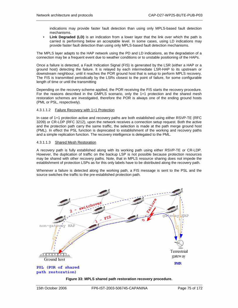
Network architecture and protocols CAP-D27-WP25-BUTE-PUB-P03
15th October 2006 FP6-IST-2003-506745-CAPANINA Page 75 of 172
indications may provide faster fault detection than using only MPLS-based fault detection mechanisms.
• Link Degraded (LD) is an indication from a lower layer that the link over which the path is carried is performing below an acceptable level. In some cases, using LD indications may provide faster fault detection than using only MPLS-based fault detection mechanisms.
The MPLS layer adapts to the HAP network using the PD and LD indications, as the degradation of a connection may be a frequent event due to weather conditions or to unstable positioning of the HAPs.
Once a failure is detected, a Fault Indication Signal (FIS) is generated by the LSR (either a HAP or a ground host) detecting the failure. It is relayed by each intermediate LSR-HAP to its upstream or downstream neighbour, until it reaches the POR ground host that is setup to perform MPLS recovery. The FIS is transmitted periodically by the LSRs closest to the point of failure, for some configurable length of time or until the transmitting
Depending on the recovery scheme applied, the POR receiving the FIS starts the recovery procedure. For the reasons described in the GMPLS scenario, only the 1+1 protection and the shared mesh restoration schemes are investigated, therefore the POR is always one of the ending ground hosts (PML or PSL, respectively).
4.3.1.1.2 Failure Recovery with 1+1 Protection
In case of 1+1 protection active and recovery paths are both established using either RSVP-TE (RFC 3209) or CR-LDP (RFC 3212), upon the network receives a connection setup request. Both the active and the protection path carry the same traffic, the selection is made at the path merge ground host (PML). In effect the PSL function is deprecated to establishment of the working and recovery paths and a simple replication function. The recovery intelligence is delegated to the PML.
4.3.1.1.3 Shared Mesh Restoration
A recovery path is fully established along with its working path using either RSVP-TE or CR-LDP. However, the duplication of traffic on the backup LSP is not possible because protection resources may be shared with other recovery paths. Note, that in MPLS resource sharing does not impede the establishment of protection LSPs as for this only labels have to be distributed along the recovery path.
Whenever a failure is detected along the working path, a FIS message is sent to the PSL and the source switches the traffic to the pre-established protection path.
Figure 33: MPLS shared path restoration recovery pr ocedure.

Network architecture and protocols CAP-D27-WP25-BUTE-PUB-P03
15th October 2006 FP6-IST-2003-506745-CAPANINA Page 76 of 172
4.3.2 GMPLS-based Recovery over Wavelength Switched HAP Networks
The inter-HAP network in this scenario is operated as a wavelength routed free-space optical network [51]. The HAPs are assumed to have all-optical wavelength switching capabilities. The optical domain is assumed to be managed using the GMPLS protocol suite, therefore the HAPs must implement the functionality of the Label Switch Routers (LSR) defined in the GMPLS standards (RFC 3945, RFC 3471). Wavelength routed light paths are considered as Label Switched Paths (LSP) and established by either the RSVP-TE (RFC 3473) or the CR-LDP (RFC 3472) protocols. In this scenario light path and LSP will be used as fully interchangeable synonyms.
Figure 34: GMPLS over WDM HAP network topology.
In the HAP network HAPs maintains connections (aside from the HAP-to-HAP connections) to mobile hosts and/or to terrestrial gateways that provide connection to the internet backbone network (see figure 1). Simple scenarios contain only one gateway-HAP; however, the presence of multiple gateway-HAPs may be desirable in more complex network topologies.
Non-gateway HAPs forward user traffic to the terrestrial core network through a gateway HAP. Therefore, every non-gateway HAP must be connected to a gateway-HAP with GMPLS tunnels (label switched paths, LSPs), which in this case are wavelength routed optical connections. As a consequence of wavelength routing, these connections are dedicated to serve the communication of the two ending HAPs (which are the label edge routers (LERs)). The bidirectional communication between the ending HAPs requires two parallel connections, one for each direction.
There are two main issues that must be considered in the process of network design: • Firstly, free-space optical connections between the HAPs are highly failure prone mainly due
to the unreliable weather conditions and the positional instability of the HAPs. To tackle these difficulties appropriate protection/restoration schemes must be applied. The GMPLS standard offers various protection/restoration schemes, the details of these schemes will be discussed in the next section.
• Secondly, the mobility of the hosts requires special functions to be implemented in the optical network. The data loss during handover must be minimized by supporting soft-handovers between neighbouring HAPs which requires the assistance of the HAP network.
Network architecture and protocols CAP-D27-WP25-BUTE-PUB-P03
15th October 2006 FP6-IST-2003-506745-CAPANINA Page 77 of 172
4.3.2.1 HAP-to-HAP Connection Recovery
GMPLS protection/restoration schemes are able to restore connections only after a failure of the HAP-to-HAP domain (blue area on Figure 31); recovery strategy after HAP-to-ground failures (red and green areas on Figure 31 needs additional provisioning methods and will be discussed later.
The GMPLS management system supports different protection/restoration schemes. In the GMPLS terminology the distinction between protection and restoration is made based on the resource allocation done during the recovery path establishment. Efficient resource utilization is vital in the HAP network. For this reason, only path (end-to-end) protection/restoration schemes are investigated. The definition of the two scheme types are:
• Path protection: denotes the paradigm whereby one or more dedicated protection light paths are fully established to protect one or more working light paths. For a protection path, this implies that route computation took place, that the path was fully signalled all the way, and that its resources were fully selected and cross-connected at all intermediate HAPs between the ingress and egress HAPs. Indeed, it means that no signalling takes place to establish the protection path when a failure occurs. However, various other kinds of signalling may take place between the ingress and egress HAPs for fault notification, to synchronize their use of the protection path, for reversion, etc.
• Path restoration: denotes the paradigm whereby some restoration resources may be pre-computed, signalled, and selected a priori, but not cross-connected to restore a working light path. The complete establishment of the restoration light path occurs only after a failure of the working path, and requires some additional signalling.
Taking into account the expected performance, the following two schemes are proposed. Recovery mechanism will described
4.3.2.1.1 1+1 Dedicated Path Protection
The low reliability of the free-space optical links and the intention to minimize recovery times when failures occurs makes 1+1 dedicated protection a reasonable design decision.
In this case the protection light path is fully established and cross-connected, simultaneously with the working path using either RSVP-TE or CR-LDP protocols. Traffic is simultaneously sent on both paths and received from one of the functional paths by end HAP. If the signal power of the currently used path degrades under a certain limit, the destination switches to other path (in this scheme the two paths are practically equivalent). There is no explicit signalling involved with this mode of protection.
4.3.2.1.2 Shared Mesh Path Restoration
On the other hand, 1+1 dedicated protection is highly resource consuming compared to shared mesh restoration where the protection resources are pre-computed, reserved, but not cross-connected. Advantages of this scheme include very efficient resource utilization, simple route and wavelength assignment (RWA) algorithms. The main disadvantage of the end-to-end restoration is the slow recovery compared to dedicated protection schemes where the protection resources are cross-connected before the failure. While the recovery after a failure on the working path of the 1+1 protection is a simple incoming traffic selection at the destination node, the recovery process of the shared-path restoration includes several steps as shown on Figure 35:
• Failure detection, there are to cases: o A HAP in the working path detects failure event by experiencing signal power
degradation, loss of signal, absence of liveness messages from the upstream neighbour, or by any other means. The detecting nodes must determine the identities of all light paths that are affected by the failure and send an End-to-End Failure Indication message to the source HAP of each path. For scalability reasons, Failure Indication messages may contain the identity and the status of multiple LSPs rather than a single one. Each intermediate HAP receiving such a message must forward the message to the appropriate next HAP such that the message would ultimately reach the source HAP of the path. However, there is no requirement that this message flows toward the source along the same path as the failed LSP. Furthermore, if an intermediate node is itself generating a Failure Indication message, there should be a mechanism to suppress all but one source of Failure Indication
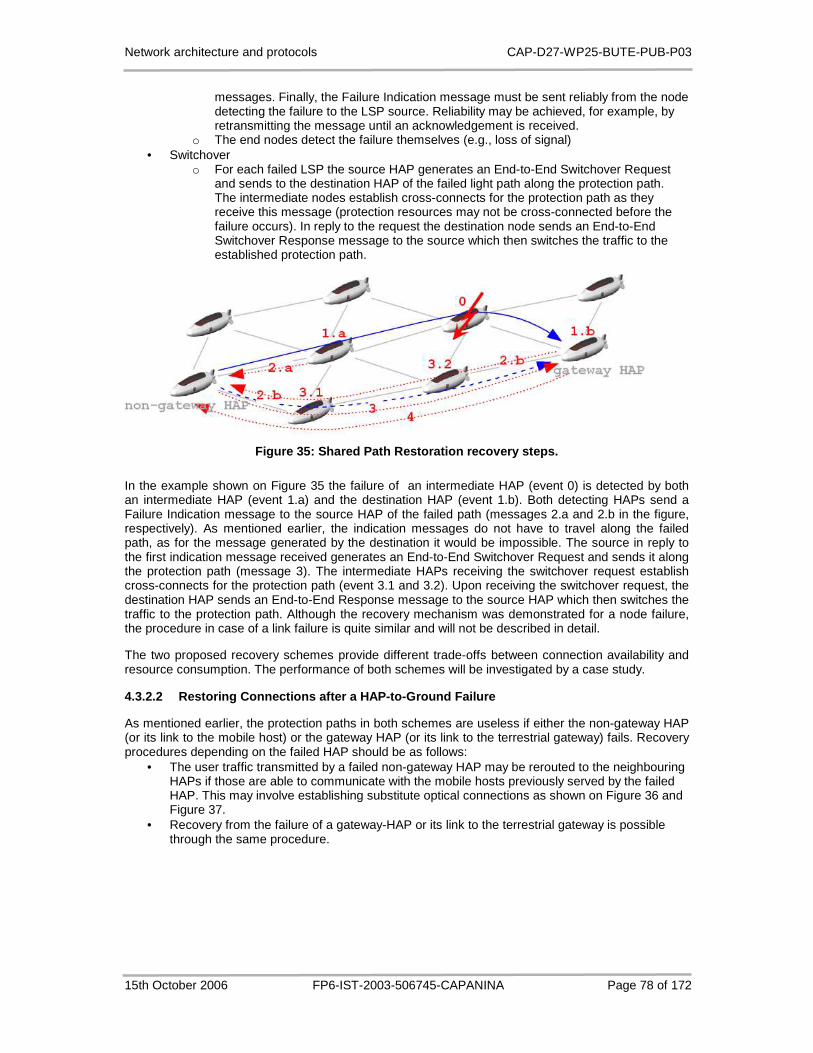
Network architecture and protocols CAP-D27-WP25-BUTE-PUB-P03
15th October 2006 FP6-IST-2003-506745-CAPANINA Page 78 of 172
messages. Finally, the Failure Indication message must be sent reliably from the node detecting the failure to the LSP source. Reliability may be achieved, for example, by retransmitting the message until an acknowledgement is received.
o The end nodes detect the failure themselves (e.g., loss of signal) • Switchover
o For each failed LSP the source HAP generates an End-to-End Switchover Request and sends to the destination HAP of the failed light path along the protection path. The intermediate nodes establish cross-connects for the protection path as they receive this message (protection resources may not be cross-connected before the failure occurs). In reply to the request the destination node sends an End-to-End Switchover Response message to the source which then switches the traffic to the established protection path.
Figure 35: Shared Path Restoration recovery steps.
In the example shown on Figure 35 the failure of an intermediate HAP (event 0) is detected by both an intermediate HAP (event 1.a) and the destination HAP (event 1.b). Both detecting HAPs send a Failure Indication message to the source HAP of the failed path (messages 2.a and 2.b in the figure, respectively). As mentioned earlier, the indication messages do not have to travel along the failed path, as for the message generated by the destination it would be impossible. The source in reply to the first indication message received generates an End-to-End Switchover Request and sends it along the protection path (message 3). The intermediate HAPs receiving the switchover request establish cross-connects for the protection path (event 3.1 and 3.2). Upon receiving the switchover request, the destination HAP sends an End-to-End Response message to the source HAP which then switches the traffic to the protection path. Although the recovery mechanism was demonstrated for a node failure, the procedure in case of a link failure is quite similar and will not be described in detail.
The two proposed recovery schemes provide different trade-offs between connection availability and resource consumption. The performance of both schemes will be investigated by a case study.
4.3.2.2 Restoring Connections after a HAP-to-Ground Failure
As mentioned earlier, the protection paths in both schemes are useless if either the non-gateway HAP (or its link to the mobile host) or the gateway HAP (or its link to the terrestrial gateway) fails. Recovery procedures depending on the failed HAP should be as follows:
• The user traffic transmitted by a failed non-gateway HAP may be rerouted to the neighbouring HAPs if those are able to communicate with the mobile hosts previously served by the failed HAP. This may involve establishing substitute optical connections as shown on Figure 36 and Figure 37.
• Recovery from the failure of a gateway-HAP or its link to the terrestrial gateway is possible through the same procedure.
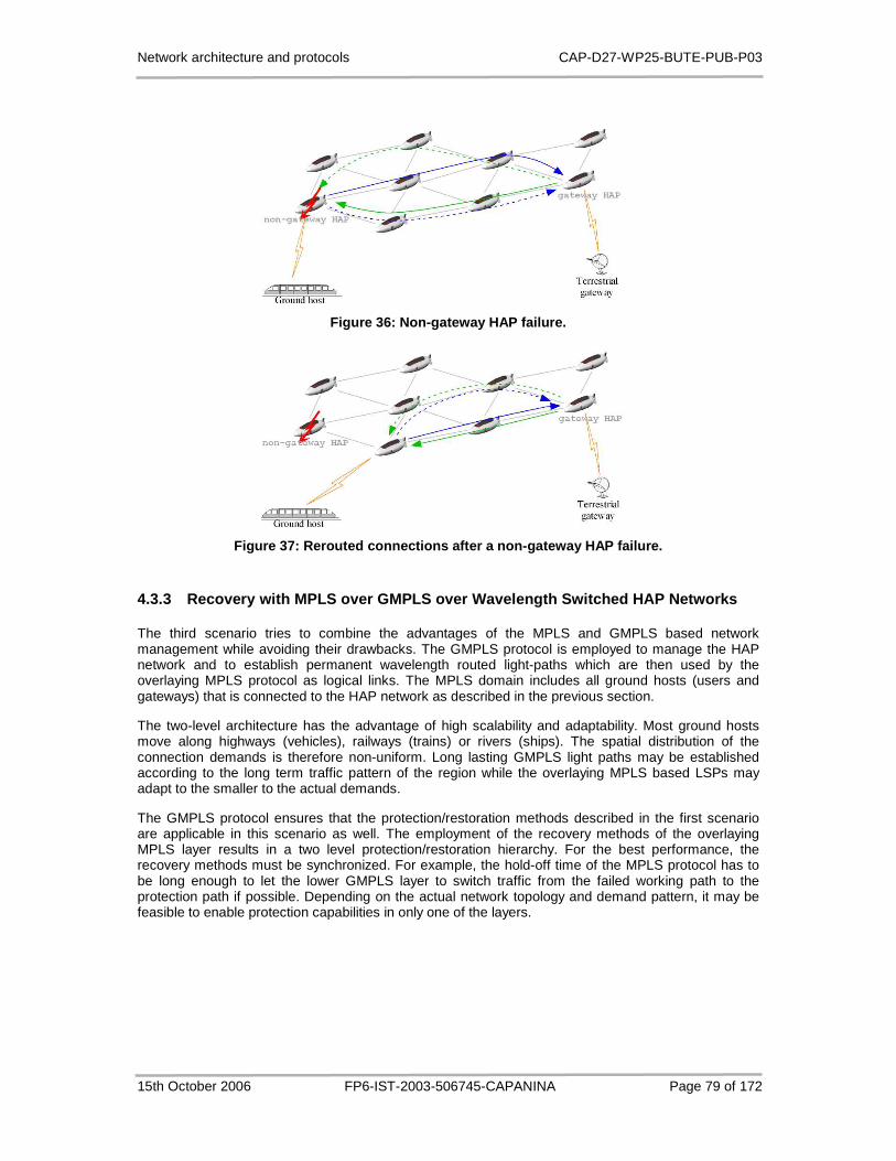
Network architecture and protocols CAP-D27-WP25-BUTE-PUB-P03
15th October 2006 FP6-IST-2003-506745-CAPANINA Page 79 of 172
Figure 36: Non-gateway HAP failure.
Figure 37: Rerouted connections after a non-gateway HAP failure.
4.3.3 Recovery with MPLS over GMPLS over Wavelength Switched HAP Networks
The third scenario tries to combine the advantages of the MPLS and GMPLS based network management while avoiding their drawbacks. The GMPLS protocol is employed to manage the HAP network and to establish permanent wavelength routed light-paths which are then used by the overlaying MPLS protocol as logical links. The MPLS domain includes all ground hosts (users and gateways) that is connected to the HAP network as described in the previous section.
The two-level architecture has the advantage of high scalability and adaptability. Most ground hosts move along highways (vehicles), railways (trains) or rivers (ships). The spatial distribution of the connection demands is therefore non-uniform. Long lasting GMPLS light paths may be established according to the long term traffic pattern of the region while the overlaying MPLS based LSPs may adapt to the smaller to the actual demands.
The GMPLS protocol ensures that the protection/restoration methods described in the first scenario are applicable in this scenario as well. The employment of the recovery methods of the overlaying MPLS layer results in a two level protection/restoration hierarchy. For the best performance, the recovery methods must be synchronized. For example, the hold-off time of the MPLS protocol has to be long enough to let the lower GMPLS layer to switch traffic from the failed working path to the protection path if possible. Depending on the actual network topology and demand pattern, it may be feasible to enable protection capabilities in only one of the layers.
Network architecture and protocols CAP-D27-WP25-BUTE-PUB-P03
15th October 2006 FP6-IST-2003-506745-CAPANINA Page 80 of 172
4.4 Summary
Section 4.2 described the network architecture implications of using multiple platforms with non-overlaid, partially overlaid and completely overlaid coverage areas by introducing additional network elements/functionality. We proposed two different architectures, with regard to complexity of additional elements / functionality, which should be installed in the system. The Basic utilisation of multiple HAPs additional network element is added at user's premises, allowing the capacity increase on outbound connections only. The advanced of multiple HAPs is more complex and requires also the load balancing router at the gateway, allowing the load balancing in both directions, outbound and inbound.
The proposed Basic utilization of multiple HAPs can be used also in the case of mobile users who are roaming in the HAP network on the train and do not use their own home IP address (i.e. they only use the IP address assigned by DHCP server on the train). Of course, the train must be in the coverage areas of more HAPs and equipped with two antennas. However, using of multiple interfaces for mobile networks (routers) and enabling a mobile host to be reached by its global address (e.g. MIP) brings much more complexity in the system (e.g. tunnelling problems, addressing problems) and needs additional further in depth investigation.
It is worth noting that all proposed solutions also improve the reliability and resilience of the HAP system.
In Section 4.3 three types of network errors were identified. Three different solutions were proposed for managing the connections between the terrestrial-gateways and the routers on the ground hosts with the consideration of error detection and recovery.
The first, GMPLS based architecture has the advantage of simplicity (minimal additional complexity at the HAPs), but only the inter-HAP portion of the connections can be protected, recovery after failures of the HAP-to-ground links needs time consuming and complex rerouting procedures.
The three different failure domains can be protected with the same schemes applying MPLS based network management (scenario 2). The MPLS domain includes both the terrestrial-gateways and the ground hosts; therefore recovery LSPs are able to protect the whole working LSP between the ground hosts. Scalability is achieved through the packet-switched LSPs at the price of additional complexity of packet processing at every HAP.
Combining the two management layers results in a two-level architecture described in the last scenario. Long lasting GMPLS light paths may established according to the traffic pattern of the region. MPLS based LSPs use light paths as logical links and adapt to the dynamic changes of the connection demands. The protection schemes of the overlaying layers may be combined for the best performance.
Network architecture and protocols CAP-D27-WP25-BUTE-PUB-P03
15th October 2006 FP6-IST-2003-506745-CAPANINA Page 81 of 172
5 Network Layer Mobility Support
5.1 Introduction
In the following chapter the network layer protocols and algorithms for provision of mobility support in the specific operating environment involving aerial platforms are studied. First, an overview of general approach, including either mobile end-nodes or mobile networks is given. Then a concept of mobile routers is presented. In particular, we consider a scenario in which network connectivity is provided to the passengers on-board a train. We designate this particular scenario as HAP-to-train scenario. Communication to the global network is most of the time provided through a High Altitude Platform (HAP) network.
HAP support for mobile users should take into account the specific properties of the HAP system and should enable service provision to end user terminals on-board moving vehicles. Scarce wireless resources call for efficient routing support at the network layer. In order to achieve as optimal user experience as possible, a hierarchical approach to mobility support is required. The routing problem has to be split into macro-, micro- and even access-level, thus exploiting the possibilities of handling mobility locally.
The concept of mobile networks, where a group of nodes move together and access the global network through a mobile router, has been widely recognized as an important future mobility scenario. Different standards and proposals have emerged for supporting mobility in IP networks. The main problem is that mobility has an adverse influence on the effectiveness of routing, which can be an important issue when multiple wireless links are involved; and in HAP networks user-to-HAP links, backhaul links and interplatform links are all wireless. Efficient solutions on all protocol layers are required for profitable use of scarce communication resources.
Support for path optimization has been identified as a major challenge and has been studied since the introduction of Mobile IP (MIP). With the occurrence of more complex mobility architectures that include mobile routers, route optimization is becoming even more complicated problem. Handover performance is another major field of research within network layer mobility support. The Network Mobility Working Group has proposed a network mobility (NEMO) technology that deals with these problems and allows mobile routers to roam within foreign networks in a manner similar to end-nodes.
HAP specific network environment has been studied in this chapter in the context of the network mobility technology. Issues such as efficient backhaul link utilization, home agent placement and multihoming support are investigated. Original solutions are proposed and some of them are general enough also to be applied to other types of access networks.
This chapter is organized as follows. Section 5.2 describes the network architecture that was considered in the investigation of mobility routing issues. A description of hierarchical mobility architecture is provided in Section 5.3. Procedures at access-, micro- and macro-level of mobility are explained and a term multi-level mobility is introduced. In Section 5.4 the concepts of Mobile IP, Hierarchical MIP (HMIP) and mobile routers are introduced. We show why efficient route optimization is important for HAP networks and discuss how propositions that have emerged recently in the Internet community fit with HAP network architecture. Backhaul link utilization is presented as a major issue in Section 5.5, which deals with route optimization for network mobility. Proxy Mobility Anchor Point functionality is proposed as a solution to the previously identified intra-domain optimization issue in multi-level MIP architectures. The effectiveness of the proposed functionality is evaluated, both numerically and by computer simulations. An alternative solution to the problem is Proxy Home Agent functionality, which can be applied in environments without HMIP support. The functionality is shortly described at the end of Section 5.5. Section 5.6 provides an alternative approach to alleviate triangular routing problem by home agent placement optimization. The home agent placement optimization is possible because of localized mobility of mobile routers. Network performance is studied in a real environment network scenario using an empirical channel model for HAP to train communications. The performance is evaluated in terms of link utilization and flow performance. The topic of Section 5.7 is multihoming in HAP networks. We identify multihoming configurations that best suit to HAP network and analyse the benefits of using multiple home agents and multiple access interfaces
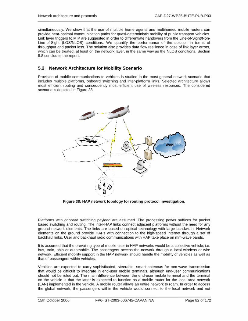
Network architecture and protocols CAP-D27-WP25-BUTE-PUB-P03
15th October 2006 FP6-IST-2003-506745-CAPANINA Page 82 of 172
simultaneously. We show that the use of multiple home agents and multihomed mobile routers can provide near-optimal communication paths for quasi-deterministic mobility of public transport vehicles. Link layer triggers to MIP are suggested in order to differentiate handovers from the Line-of-Sight/Non-Line-of-Sight (LOS/NLOS) conditions. We quantify the performance of the solution in terms of throughput and packet loss. The solution also provides data flow resilience in case of link layer errors, which can be treated, at least on the network layer, in the same way as the NLOS conditions. Section 5.8 concludes the report.
5.2 Network Architecture for Mobility Scenario
Provision of mobile communications to vehicles is studied in the most general network scenario that includes multiple platforms, onboard switching and inter-platform links. Selected architecture allows most efficient routing and consequently most efficient use of wireless resources. The considered scenario is depicted in Figure 38.
Figure 38: HAP network topology for routing protoco l investigation.
Platforms with onboard switching payload are assumed. The processing power suffices for packet based switching and routing. The inter-HAP links connect adjacent platforms without the need for any ground network elements. The links are based on optical technology with large bandwidth. Network elements on the ground provide HAPs with connection to the high-speed Internet through a set of backhaul links. User and backhaul radio communications with HAP take place on mm-wave bands.
It is assumed that the prevailing type of mobile user in HAP networks would be a collective vehicle; i.e. bus, train, ship or automobile. The passengers access the network through a local wireless or wire network. Efficient mobility support in the HAP network should handle the mobility of vehicles as well as that of passengers within vehicles.
Vehicles are expected to carry sophisticated, steerable, smart antennas for mm-wave transmission that would be difficult to integrate in end-user mobile terminals, although end-user communications should not be ruled out. The main difference between the end-user mobile terminal and the terminal on the vehicle is that the latter is expected to function as a mobile router for the local area network (LAN) implemented in the vehicle. A mobile router allows an entire network to roam. In order to access the global network, the passengers within the vehicle would connect to the local network and not
Network architecture and protocols CAP-D27-WP25-BUTE-PUB-P03
15th October 2006 FP6-IST-2003-506745-CAPANINA Page 83 of 172
directly to the HAP. Often, they will require global mobility, in which case they will have to use their own MIP, in addition to the MIP performed by the mobile router. Hence so-called two-level mobility management will take place.
5.3 Hierarchical Approach to Mobility Support
The limited radio spectrum should be used as efficiently as possible, as the wireless links typically represent the bottleneck of communication networks. In HAP networks both access links and backhaul links to gateways and application servers are wireless. Moreover, backhaul links carry aggregate user traffic and therefore their unnecessary use must be avoided as much as possible. Note that user data does not necessarily have to pass through the ground core network — only user-to-HAP and HAP-to-HAP links may be involved.
It is also important to keep handover procedures fast and to avoid single points of failure in the nodes that handle mobility. A possible approach to solve the described challenges is to split the problem of routing to a mobile node into micro- and macro-mobility parts. Apart from that division, access mobility is considered as the lowest level of mobility. While micro- and macro-mobility divide the network layer mobility events into those that can be handled locally and those with global impact on the route, the access mobility is dealt with on the link layer within the scope of a single HAP. Access mobility in the 3rd generation networks refers to the methods and protocols that ensure mobility within the scope of a single Radio Network Controller (RNC), which corresponds to a single HAP in our operating scenario.
5.3.1 Access-Level Mobility
Mobility within a single HAP is proposed to be implemented on link layer, i.e. as access mobility, because loose coupling with network layer mobility enables exploitation of specific HAP access technology. This is not possible if IP-mobility is employed at cell level.
Furthermore, Mobile IP and its micro-mobility extensions as a highly developed mobility management solutions do not attempt to solve access control to a link. Note that wireless access networks require additional link level security, as the mobile network itself has to allow access to the resources for the mobile node before the Mobile IP signalling actually consumes radio resources. These problems are solved by existing authentication, authorization and accounting functionality.
Access level mobility is expected to take care of movements across the cell boundaries for the cells that are beamed from a single platform. In this way the entire HAP coverage area is seen as a single link by the network layer entities.
5.3.2 Micro-Mobility
In order to solve inter-platform handoff latency problem, several IP-based micro-mobility protocols have been developed. For instance, a set of extensions of the MIP have been proposed by the research community. The extensions, such as Cellular IP [49], Hawaii [53] or TeleMIP [54], propose a form of tree-like hierarchy of local routers. The infrastructure nodes in these schemes are arranged in a strict inverse tree structure beneath the root router, i.e. every node is a child of one and only one other node, and may be a parent of zero, one or more other nodes.
A tree like topology of nodes in HAP network requires involvement of backhaul links in the tree. An issue of route optimization arises for HAP-to-HAP communication. It is not reasonable to route this type of traffic on backhaul links.
The second group, i.e. the tunnel-based micro-mobility schemes, performs registration and different kind of encapsulation in hierarchical fashion. A concatenation of tunnels is created over local network. A typical representative of this group is the Hierarchical Mobile IP (HMIP) proposal [55], (RFC 4140). In IPv4 networks, regional registration plays a similar role.
Mechanisms in both groups of micro-mobility schemes define a kind of Anchor Node (AN) that is responsible for micro-mobility within the area. For instance, in HMIP the anchor node is called Mobility Anchor Point (MAP).

Network architecture and protocols CAP-D27-WP25-BUTE-PUB-P03
15th October 2006 FP6-IST-2003-506745-CAPANINA Page 84 of 172
There are two alternatives where to locate the AN within the HAP network. If the AN is placed on the ground, backhaul links are included into domain tree. The AN is extensively involved into message exchange within the micro-mobility domain, which puts additional load on scarce radio resources on the backhaul link. The load increases significantly if mobile routers are involved. On the other hand, locating the AN within the platform network increases the load on the selected platform and reduces the inter-platform network efficiency. Note that platforms are connected in a mesh topology, which cannot be exploited in full if a tree-topology is imposed.
The single versus multiple-HAP micro-mobility area is illustrated in Figure 39. The AN advertises allocated IP addresses to external IP networks, maintains link-level connectivity with mobile nodes and stores location information about mobile nodes within the area. The advantages of single-HAP micro-mobility are mainly the following:
• Maximised routing efficiency:
Route optimality is not affected by the AN location because it is placed on the network edge. This is one of the drawbacks of multiple-HAP configuration. Furthermore, if the AN is ground based, then backhaul links are involved, even for communication between the mobile nodes within the same micro-mobility area.
• Higher scalability:
New HAPs may be added to the network without any impact on micro-mobility management in the rest of the network.
AN
Platform Network
Ground Network
AN
AN
AN - Anchor Node
Platform Network
Ground Network
AN
Figure 39: Single-HAP vs. multiple-HAP micro-mobili ty area.

Network architecture and protocols CAP-D27-WP25-BUTE-PUB-P03
15th October 2006 FP6-IST-2003-506745-CAPANINA Page 85 of 172
There are severe drawbacks to the single-HAP micro-mobility solution:
• More frequent global path updates:
Change of IP address is required when the user moves into the coverage area of a new platform. This is a macro-mobility event that requires a global path update. However, the coverage area of a single HAP is expected to be at least 60 km in diameter, therefore global path updates are still manageable. For example, a train at a speed of 250 km/h stays within the HAP coverage area for up to 14 minutes.
• Inter-platform handoff latency issue:
This remains an open issue. It may be solved by current investigations that strive to define micro-mobility extensions of the MIP.
• Lower degree of location anonymity:
Route optimization and processing of ICMP messages reveals the MN's point of attachment to the rest of the world with the precision of a single HAP.
Due to above reasons, micro-mobility area is expected to span multiple HAP platforms. In addition to reduced inter-platform handoff latency, such configuration offers less frequent global path updates and higher degree of location anonymity. Because micro-mobility schemes affect route optimality, as it is shown in the following sections, we propose and evaluate some modifications to the Hierarchical Mobile IP protocol.
5.3.3 Macro-Mobility
While micro-mobility enables transparent mobility within a limited area, macro-mobility procedures make possible transparent movements of a mobile node between the micro-mobility areas on the global scale. Due to address change, all transport layer connections will break down unless appropriate mechanisms are introduced.
Several macro-mobility protocols have been proposed in recent years. Although all of them have the common goal of location transparency, they differ from each other as they operate in different protocol layers. For instance, Session Initiation Protocol (SIP) operates at the application layer [56], while Mobile IP (MIP) is a network layer protocol (RFC 3344), [57]. SIP is limited by the performance of TCP or UDP over wireless links. MIP is considered as the most promising IP macro-mobility mechanism. It defines a set of entities and procedures that enable a mobile node to retain its home address on the move, without requiring changes in the intermediate routing nodes.
In case of multiple platform networks, time-critical operations, such as interplatform handover, cannot be handled just by macro-mobility protocol. Namely, MIP suffers from several weaknesses that require introduction of micro-mobility support in networks.
The basic MIP includes the movement detection procedures and registration with the home agent that can trigger handover. However, this can not be achieved in a fast way. Every time the mobile node gets a new local IP address, movement detection and registration steps must be completed. It is the mobile node that initiates these processes. Movement detection latency and registration latency are serious limitations for real-time communications. The overall latency may be large, since the movement detection mechanisms in MIP are based on either the expiration of the lifetime of foreign agent advertisements, or on the comparison of the address prefix of two different agent advertisements. The registration latency may be even larger as the home agent may be located anywhere on the Internet.
Network architecture and protocols CAP-D27-WP25-BUTE-PUB-P03
15th October 2006 FP6-IST-2003-506745-CAPANINA Page 86 of 172
5.3.4 Other Issues
Another important issue that influences the user mobility infrastructure is how the HAPs are distributed between network operators. The simplest scenario is that one network operator operates all the HAPs in particular region. In this case the user roams to that network and is connected to the same operator throughout the coverage region of HAP system. However it can be expected that there will be more than one HAP network operator with different numbers of HAPs. Some of them will be inter-connected via terrestrial links, but also via interplatform links.
5.4 Routing to Mobile Nodes
5.4.1 Mobile IP
The Mobile IP protocol defines a set of entities and procedures that enable a mobile node to retain its home address on the move, without requiring changes in the intermediate routing nodes. Routing to the mobile node (MN) is done partially to the home address (HoA) and partially to the care-of address (CoA), that is a unicast routable address associated with a mobile node visiting a foreign micro-mobility area. While the mobile node is away from home, it registers its current CoA with the home agent (HA). The agent intercepts packets from a correspondent node (CN) destined for the mobile node's home address, encapsulates them, and tunnels them to the mobile node's registered CoA. The correspondent node is the node with which the mobile node is communicating. MN has to report any change in current CoA by sending a binding update (BU) to its home agent.
Registration and packet forwarding in MIPv4 is managed through a foreign agent (FA), whereas in MIPv6, the foreign agent is not needed. A foreign agent is actually a router for mobile nodes on a visited network that operates as the end-point for tunnels from the HA and provides CoA on behalf of the mobile nodes. Note that in the wireless networks the FA is located before wireless link. In the radio resource perspective, the use of FA is more effective because MIPv6 tunnels are established over the radio interface.
MIPv6 [57] builds on IPv6 transport technology, which gives it an advantage over MIPv4 (RFC 3344). Integrated route optimization functionality is one of the benefits of MIPv6. MIPv4 in its basic form suffers from the triangular routing problem, where all packets sent to a mobile node while away from home are intercepted by its home agent and tunnelled to the mobile node; thus taking a long detour. In MIPv6 the CN can send IP packets directly to the MN after the optimization step takes place. The optimization is triggered by the MN. A binding update, similar to the update that is sent to the HA, is used to inform the CN about the MN's current location. Note that several messages must be exchanged in this process because it involves a return routability test and binding acknowledgement.
5.4.2 Hierarchical MIP
In order to improve MIP scalability, hierarchical mobility architecture was introduced ([55], (RFC 4140)) on micro-mobility level. Without any hierarchical structure the number of BUs increases proportionally as the network grows and the number of MNs increases. Efficient mobility management should keep network load low and provide optimum routing of packets. HMIP technology reduces frequent location registrations and the time needed for handovers.
The protocol differentiates the intra-site mobility from the inter-site mobility. A site can be an ISP network, a company network, a set of LANs or even a single LAN. A new node, called the Mobility Anchor Point (MAP), can be located at any level in a hierarchical network of routers. It can be viewed as a local HA for the site. The mobile node obtains the on-link care-of address (LCoA) and regional care-of address (RCoA). The RCoA is an address of the mobile node in the MAP domain. Note that in MIP only CoA, an equivalent to LCoA, is allocated and used. Before registering the RCoA with the HA and correspondent nodes, the mobile node registers with the MAP in order to establish a binding between the RCoA and LCoA.
When a mobile node moves within the site, a new LCoA is allocated on its new access point. Because the RCoA remains constant, only local binding updates are required within the MAP area. As a result,

Network architecture and protocols CAP-D27-WP25-BUTE-PUB-P03
15th October 2006 FP6-IST-2003-506745-CAPANINA Page 87 of 172
a foreign correspondent node, i.e. a CN that does not reside within the same MAP domain, is aware only of MN's inter-site mobility. As a consequence, all inter-site traffic is routed through MAP, which is not always optimal. In order to cope with this problem, the specification allows several MAPs to be deployed for the same area of nodes. Furthermore, MAP can be placed within the border router to improve path efficiency.
Intra-domain route optimization is proposed to eliminate path deviations from its optimum, which would occur if all intra-site traffic were routed through the MAP [55]. Correspondent nodes that reside within the same site as the mobile node get special treatment. They are referred to as local CNs. The BUs to these nodes carry LCoA instead of RCoA. Registration updates are sent more frequently, i.e. on every point-of-attachment change. In this way an optimal route can be established between the CN and the MN within the site. The RFC 4140 is more restrictive as to which CN the MN sends a BU with LCoA as the source address. The CN must be attached to the same link as the MN in order to receive the BU with LCoA. This is not route efficient if the MAP is placed away from the network edge.
A mechanism is proposed to utilize network resources more efficiently by the choice of MAP. In a way, it can be considered as a substitute for intra-domain optimization. The alternative use of more than one MAP is permitted for redundancy and as an optimization for the different mobility scenarios experienced by mobile nodes. MAPs are used independently of each other. In order to achieve as optimal route as possible, the most suitable MAP should be selected for local CNs. This will avoid sending all packets via the distant MAP, hence resulting in more efficient routing. The mobile node may need some sophisticated algorithms to be able to select the most appropriate MAP. The IETF specifications only provide a default algorithm for selecting the most distant and furthest available MAP, which does not offer any intra-domain route optimization capability.
Distinguishing a local CN from one further away has not been addressed yet. The problem is not easy to solve because very little information is available to MNs about the network topology in which they roam. In fact, the MAP option in router advertisement messages includes only the distance vector from the mobile node, the preference for the particular MAP, the MAP's global IP address and the MAP's subnet prefix. Currently only CNs on the same link are recognized as local CNs. On the basis of the MAP's subnet prefix it would be possible to identify CNs within the same MAP domain from CN's RCoA, providing that CNs are also mobile nodes.
The multi-level hierarchy of MAPs is not supported by the RFC 4140 in contrast to the proposal in [55], because it is not required for a higher handover performance, which is one of the reasons for introducing HMIP in the first place. Moreover, it is prohibited to select more than one MAP and to force packets to be sent from the higher MAP down through a hierarchy of MAPs, because this may add forwarding delays and affect the robustness of IP routing.
5.4.3 Mobile Routers
When mobile routers (MRs) are present within the site, the intra-site optimization becomes an even greater problem. Mobility management for end-nodes is well defined in current MIP specifications, but the support for mobile networks has not been addressed. This kind of support will be needed for various types of communication devices moving on vehicles. The support is particularly important for HAP-to-train scenario.
MIPv4 and MIPv6 have been designed for end node mobility. Network mobility was not completely taken out of the specifications. The designers of MIPv4 claim that it could support mobile networks equally as mobile nodes. This may be true for MIPv4; however, in [58] the authors show that MIPv6 cannot support network mobility without some changes. Recently, MIP extensions for mobile routers have been studied within the IETF Network Mobility Working Group [59] [60].
Mobility principles, similar to those for end-nodes, apply to mobile routers. There is an HA that intercepts all packets for an entire network domain and forwards them to the mobile router. Note that MR's sub-network address prefix is bound to MR's CoA, which enables tunnelling sub-network traffic to a remote location. This differs from MIP for end-nodes, where a single address is bound to CoA. MR implements a movement detection mechanism and performs registration with its HA.
In contrast to MIP for end-nodes, path optimization for mobile routers remains a largely open challenge. Although several proposals exist that deal with the path optimization issue [58] [61] [62] [63]
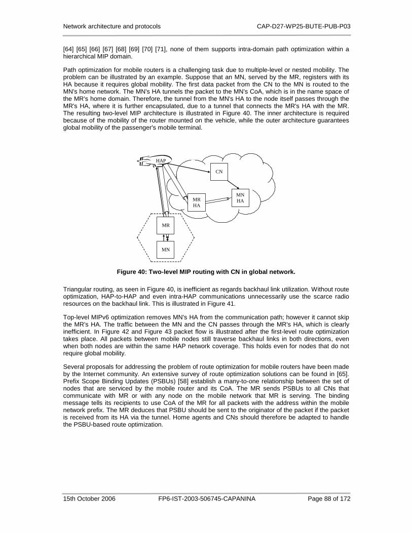
Network architecture and protocols CAP-D27-WP25-BUTE-PUB-P03
15th October 2006 FP6-IST-2003-506745-CAPANINA Page 88 of 172
[64] [65] [66] [67] [68] [69] [70] [71], none of them supports intra-domain path optimization within a hierarchical MIP domain.
Path optimization for mobile routers is a challenging task due to multiple-level or nested mobility. The problem can be illustrated by an example. Suppose that an MN, served by the MR, registers with its HA because it requires global mobility. The first data packet from the CN to the MN is routed to the MN's home network. The MN's HA tunnels the packet to the MN's CoA, which is in the name space of the MR's home domain. Therefore, the tunnel from the MN's HA to the node itself passes through the MR's HA, where it is further encapsulated, due to a tunnel that connects the MR's HA with the MR. The resulting two-level MIP architecture is illustrated in Figure 40. The inner architecture is required because of the mobility of the router mounted on the vehicle, while the outer architecture guarantees global mobility of the passenger's mobile terminal.
MN HA
CN
MN
MR HA
HAP
MR
Figure 40: Two-level MIP routing with CN in global network.
Triangular routing, as seen in Figure 40, is inefficient as regards backhaul link utilization. Without route optimization, HAP-to-HAP and even intra-HAP communications unnecessarily use the scarce radio resources on the backhaul link. This is illustrated in Figure 41.
Top-level MIPv6 optimization removes MN's HA from the communication path; however it cannot skip the MR's HA. The traffic between the MN and the CN passes through the MR's HA, which is clearly inefficient. In Figure 42 and Figure 43 packet flow is illustrated after the first-level route optimization takes place. All packets between mobile nodes still traverse backhaul links in both directions, even when both nodes are within the same HAP network coverage. This holds even for nodes that do not require global mobility.
Several proposals for addressing the problem of route optimization for mobile routers have been made by the Internet community. An extensive survey of route optimization solutions can be found in [65]. Prefix Scope Binding Updates (PSBUs) [58] establish a many-to-one relationship between the set of nodes that are serviced by the mobile router and its CoA. The MR sends PSBUs to all CNs that communicate with MR or with any node on the mobile network that MR is serving. The binding message tells its recipients to use CoA of the MR for all packets with the address within the mobile network prefix. The MR deduces that PSBU should be sent to the originator of the packet if the packet is received from its HA via the tunnel. Home agents and CNs should therefore be adapted to handle the PSBU-based route optimization.

Network architecture and protocols CAP-D27-WP25-BUTE-PUB-P03
15th October 2006 FP6-IST-2003-506745-CAPANINA Page 89 of 172
MN1 HA
MN2 HA
MN1
MN2
MR2 HA
MR2
HAP2
MR1 HA
HAP1
MR1
Figure 41: Two-level MIP routing for HAP-to-HAP tra ffic.
CN
MN
MR HA
HAP
MR
Figure 42: Two-level MIP routing after first-level route optimization (CN in global network).
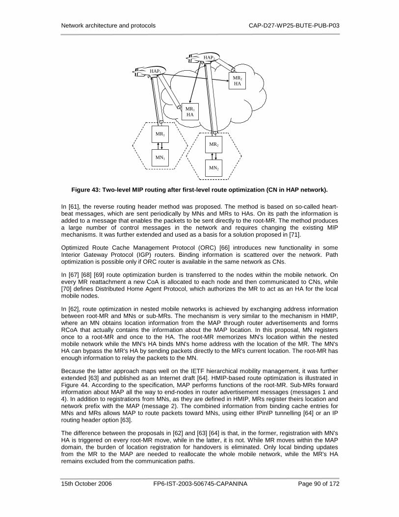
Network architecture and protocols CAP-D27-WP25-BUTE-PUB-P03
15th October 2006 FP6-IST-2003-506745-CAPANINA Page 90 of 172
MN1
MN2
MR2 HA
MR2
HAP2
MR1 HA
HAP1
MR1
Figure 43: Two-level MIP routing after first-level route optimization (CN in HAP network).
In [61], the reverse routing header method was proposed. The method is based on so-called heart-beat messages, which are sent periodically by MNs and MRs to HAs. On its path the information is added to a message that enables the packets to be sent directly to the root-MR. The method produces a large number of control messages in the network and requires changing the existing MIP mechanisms. It was further extended and used as a basis for a solution proposed in [71].
Optimized Route Cache Management Protocol (ORC) [66] introduces new functionality in some Interior Gateway Protocol (IGP) routers. Binding information is scattered over the network. Path optimization is possible only if ORC router is available in the same network as CNs.
In [67] [68] [69] route optimization burden is transferred to the nodes within the mobile network. On every MR reattachment a new CoA is allocated to each node and then communicated to CNs, while [70] defines Distributed Home Agent Protocol, which authorizes the MR to act as an HA for the local mobile nodes.
In [62], route optimization in nested mobile networks is achieved by exchanging address information between root-MR and MNs or sub-MRs. The mechanism is very similar to the mechanism in HMIP, where an MN obtains location information from the MAP through router advertisements and forms RCoA that actually contains the information about the MAP location. In this proposal, MN registers once to a root-MR and once to the HA. The root-MR memorizes MN's location within the nested mobile network while the MN's HA binds MN's home address with the location of the MR. The MN's HA can bypass the MR's HA by sending packets directly to the MR's current location. The root-MR has enough information to relay the packets to the MN.
Because the latter approach maps well on the IETF hierarchical mobility management, it was further extended [63] and published as an Internet draft [64]. HMIP-based route optimization is illustrated in Figure 44. According to the specification, MAP performs functions of the root-MR. Sub-MRs forward information about MAP all the way to end-nodes in router advertisement messages (messages 1 and 4). In addition to registrations from MNs, as they are defined in HMIP, MRs register theirs location and network prefix with the MAP (message 2). The combined information from binding cache entries for MNs and MRs allows MAP to route packets toward MNs, using either IPinIP tunnelling [64] or an IP routing header option [63].
The difference between the proposals in [62] and [63] [64] is that, in the former, registration with MN's HA is triggered on every root-MR move, while in the latter, it is not. While MR moves within the MAP domain, the burden of location registration for handovers is eliminated. Only local binding updates from the MR to the MAP are needed to reallocate the whole mobile network, while the MR's HA remains excluded from the communication paths.

Network architecture and protocols CAP-D27-WP25-BUTE-PUB-P03
15th October 2006 FP6-IST-2003-506745-CAPANINA Page 91 of 172
HAMR HAMN
MN
CN
2. BU LCoAMR-RCoAMR-MN prefix
4. RA with MAP option
5. BU LCoAMN-RCoAMN
6. BU RCoAMN-HoAMN
LCoAMN
LCoAMR
RCoAMN
RCoAMR
HoAMN HoAMR
Core Network
Nested Network
MR
MAP 1. RA with MAP option
3. BU RCoAMR-HoAMR
Figure 44: HMIP-based route optimization.
5.5 Route Optimization
5.5.1 Backhaul Link Utilization
If HMIP is applied to the HAP network and the MAP is placed on the ground, the backhaul links are involved in the HAP-to-HAP communications, which is clearly an inefficient use of scarce radio resources. Packet flow after HMIP based route optimization in the HAP network with MAP on the ground is shown in Figure 45.
In order to exclude the backhaul links from the HAP-to-HAP communications, the HMIP domain root, i.e. MAP, should be located on each platform (Figure 46). However, the advantages of hierarchical mobility are lost by placing the MAP on the very edge of the access network, which is why such solution is not acceptable. Note that some other mechanisms should be implemented in that case to improve handover performance. In the following, intra-domain routing problem is investigated in detail. Solution to the problem is proposed and evaluated.
5.5.2 Intra-domain Routing Problem
Intra-site route optimization, as proposed in HMIP, is lost when MN resides within MR's mobile network, which in turn roams within the MAP domain. This is the primary cause of the backhaul link issue, identified in the previous subsection.
In order to trigger intra-site optimization, an MN must recognize CNs within the same site. The CN that resides below MR cannot be identified as a site local node by its IP address because the address is from a different domain. The exceptions are those CNs that are also MNs. They can be recognized as being within the same MAP domain based on theirs RCoA. However, this is of little use. Even though the MN recognizes the CN as a site local node, it should not identify itself by its LCoA. A packet destined to the LCoA will be routed to the MR's HA and from there to the MN via the MAP. Instead of shortcutting the MAP, an even longer path will be used.
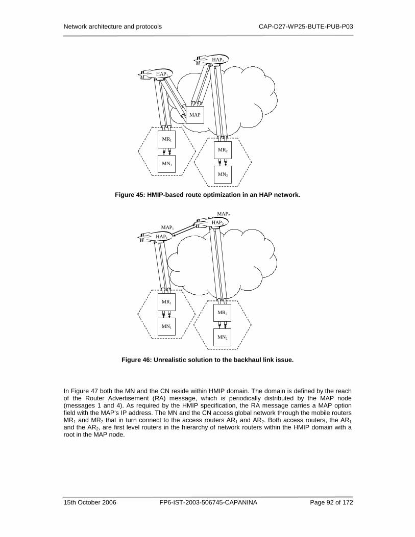
Network architecture and protocols CAP-D27-WP25-BUTE-PUB-P03
15th October 2006 FP6-IST-2003-506745-CAPANINA Page 92 of 172
MN1
MN2
MAP
HAP1
MR1
MR2
HAP2
Figure 45: HMIP-based route optimization in an HAP network.
MN1
MN2
HAP1
MR1
MAP1
MAP2
HAP2
MR2
Figure 46: Unrealistic solution to the backhaul lin k issue.
In Figure 47 both the MN and the CN reside within HMIP domain. The domain is defined by the reach of the Router Advertisement (RA) message, which is periodically distributed by the MAP node (messages 1 and 4). As required by the HMIP specification, the RA message carries a MAP option field with the MAP's IP address. The MN and the CN access global network through the mobile routers MR1 and MR2 that in turn connect to the access routers AR1 and AR2. Both access routers, the AR1 and the AR2, are first level routers in the hierarchy of network routers within the HMIP domain with a root in the MAP node.
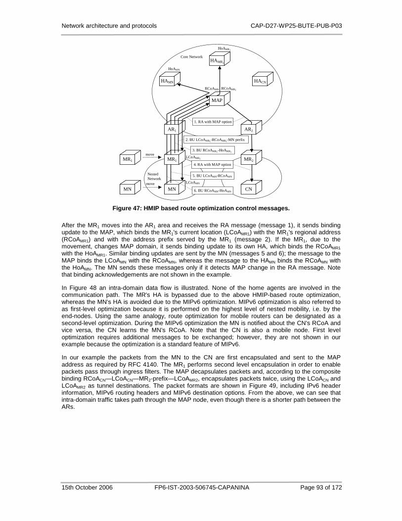
Network architecture and protocols CAP-D27-WP25-BUTE-PUB-P03
15th October 2006 FP6-IST-2003-506745-CAPANINA Page 93 of 172
HAMN
MN
4. RA with MAP option
5. BU LCoAMN-RCoAMN
6. BU RCoAMN-HoAMN
LCoAMN
LCoAMR1
RCoAMN RCoAMR1
HoAMN
Core Network
Nested Network
MR1
AR1
1. RA with MAP option
3. BU RCoAMR1-HoAMR1
CN
MR2
HACN
HAMR1
HoAMR1
MR1
MN
move
move
MAP
AR2
2. BU LCoAMR1-RCoAMR1-MN prefix
Figure 47: HMIP based route optimization control me ssages.
After the MR1 moves into the AR1 area and receives the RA message (message 1), it sends binding update to the MAP, which binds the MR1's current location (LCoAMR1) with the MR1's regional address (RCoAMR1) and with the address prefix served by the MR1 (message 2). If the MR1, due to the movement, changes MAP domain, it sends binding update to its own HA, which binds the RCoAMR1 with the HoAMR1. Similar binding updates are sent by the MN (messages 5 and 6); the message to the MAP binds the LCoAMN with the RCoAMN, whereas the message to the HAMN binds the RCoAMN with the HoAMN. The MN sends these messages only if it detects MAP change in the RA message. Note that binding acknowledgements are not shown in the example.
In Figure 48 an intra-domain data flow is illustrated. None of the home agents are involved in the communication path. The MR's HA is bypassed due to the above HMIP-based route optimization, whereas the MN's HA is avoided due to the MIPv6 optimization. MIPv6 optimization is also referred to as first-level optimization because it is performed on the highest level of nested mobility, i.e. by the end-nodes. Using the same analogy, route optimization for mobile routers can be designated as a second-level optimization. During the MIPv6 optimization the MN is notified about the CN's RCoA and vice versa, the CN learns the MN's RCoA. Note that the CN is also a mobile node. First level optimization requires additional messages to be exchanged; however, they are not shown in our example because the optimization is a standard feature of MIPv6.
In our example the packets from the MN to the CN are first encapsulated and sent to the MAP address as required by RFC 4140. The MR1 performs second level encapsulation in order to enable packets pass through ingress filters. The MAP decapsulates packets and, according to the composite binding RCoACN—LCoACN—MR2-prefix—LCoAMR2, encapsulates packets twice, using the LCoACN and LCoAMR2 as tunnel destinations. The packet formats are shown in Figure 49, including IPv6 header information, MIPv6 routing headers and MIPv6 destination options. From the above, we can see that intra-domain traffic takes path through the MAP node, even though there is a shorter path between the ARs.

Network architecture and protocols CAP-D27-WP25-BUTE-PUB-P03
15th October 2006 FP6-IST-2003-506745-CAPANINA Page 94 of 172
HAMN
MN
shorter path
Core Network
Nested Network
CN
HACN
HAMR1
MAP
AR2
MR2
AR1
MR1
Figure 48: HMIP intra-domain data flow.
src: LCoAMN dst: MAP data
src: RCoAMN dst: RCoACN
HoACN HoAMN
IPv6 hdr. IPv6 hdr. routing hdr. dst. option
From MN to MR1
src: RCoAMN dst: RCoACN
src: LCoAMN dst: MAP
src: LCoAMR1 dst: MAP
data HoACN HoAMN
IPv6 hdr. IPv6 hdr. routing hdr. dst. option
From MR1 to MAP
IPv6 hdr.
src: RCoAMN dst: RCoACN
src: MAP dst: LCoACN
src: MAP dst: LCoAMR2
data HoACN HoAMN
IPv6 hdr. IPv6 hdr. routing hdr. dst. option
From MAP to MR2
IPv6 hdr.
src: MAP dst: LCoACN data
src: RCoAMN dst: RCoACN
HoACN HoAMN
IPv6 hdr. IPv6 hdr. routing hdr. dst. option
From MR2 to CN
Figure 49: Data packet formats.
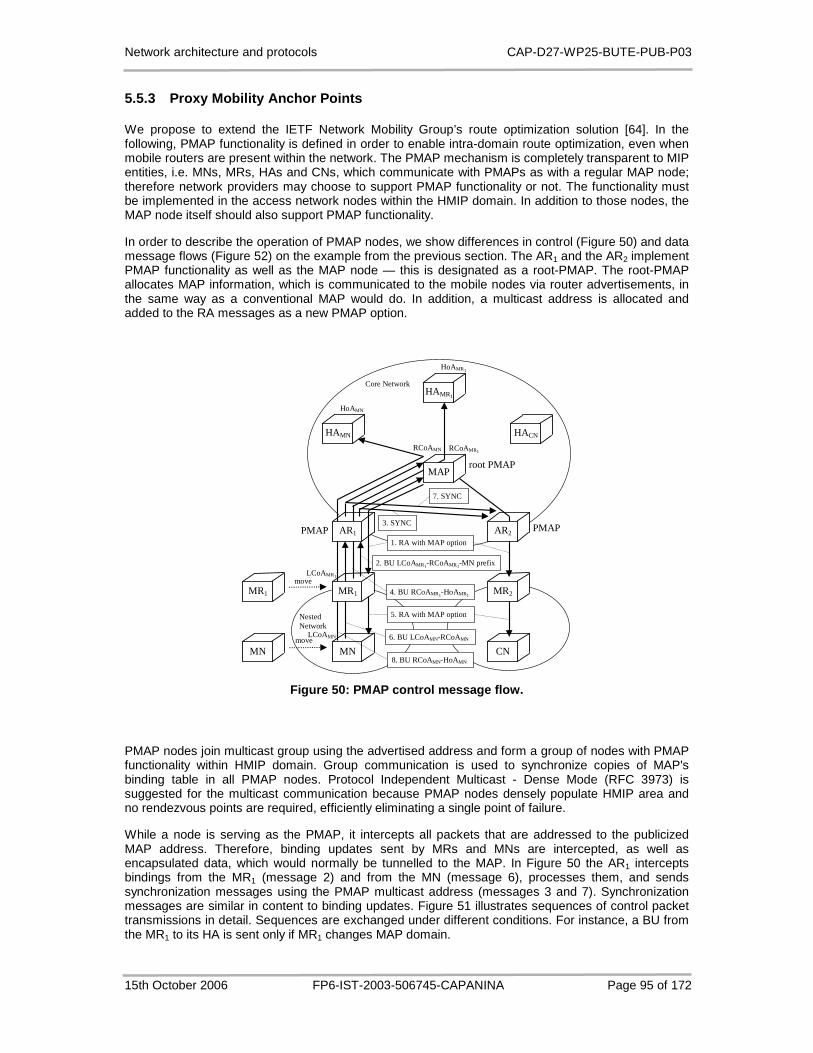
Network architecture and protocols CAP-D27-WP25-BUTE-PUB-P03
15th October 2006 FP6-IST-2003-506745-CAPANINA Page 95 of 172
5.5.3 Proxy Mobility Anchor Points
We propose to extend the IETF Network Mobility Group’s route optimization solution [64]. In the following, PMAP functionality is defined in order to enable intra-domain route optimization, even when mobile routers are present within the network. The PMAP mechanism is completely transparent to MIP entities, i.e. MNs, MRs, HAs and CNs, which communicate with PMAPs as with a regular MAP node; therefore network providers may choose to support PMAP functionality or not. The functionality must be implemented in the access network nodes within the HMIP domain. In addition to those nodes, the MAP node itself should also support PMAP functionality.
In order to describe the operation of PMAP nodes, we show differences in control (Figure 50) and data message flows (Figure 52) on the example from the previous section. The AR1 and the AR2 implement PMAP functionality as well as the MAP node — this is designated as a root-PMAP. The root-PMAP allocates MAP information, which is communicated to the mobile nodes via router advertisements, in the same way as a conventional MAP would do. In addition, a multicast address is allocated and added to the RA messages as a new PMAP option.
HAMN
MN
5. RA with MAP option
6. BU LCoAMN-RCoAMN
8. BU RCoAMN-HoAMN
LCoAMN
LCoAMR1
RCoAMN RCoAMR1
HoAMN
Core Network
Nested Network
MR1
AR1 1. RA with MAP option
4. BU RCoAMR1-HoAMR1
CN
MR2
HACN
HAMR1
HoAMR1
MR1
MN
move
move
MAP
AR2
2. BU LCoAMR1-RCoAMR1-MN prefix
root PMAP
PMAP 3. SYNC
PMAP
7. SYNC
Figure 50: PMAP control message flow.
PMAP nodes join multicast group using the advertised address and form a group of nodes with PMAP functionality within HMIP domain. Group communication is used to synchronize copies of MAP's binding table in all PMAP nodes. Protocol Independent Multicast - Dense Mode (RFC 3973) is suggested for the multicast communication because PMAP nodes densely populate HMIP area and no rendezvous points are required, efficiently eliminating a single point of failure.
While a node is serving as the PMAP, it intercepts all packets that are addressed to the publicized MAP address. Therefore, binding updates sent by MRs and MNs are intercepted, as well as encapsulated data, which would normally be tunnelled to the MAP. In Figure 50 the AR1 intercepts bindings from the MR1 (message 2) and from the MN (message 6), processes them, and sends synchronization messages using the PMAP multicast address (messages 3 and 7). Synchronization messages are similar in content to binding updates. Figure 51 illustrates sequences of control packet transmissions in detail. Sequences are exchanged under different conditions. For instance, a BU from the MR1 to its HA is sent only if MR1 changes MAP domain.
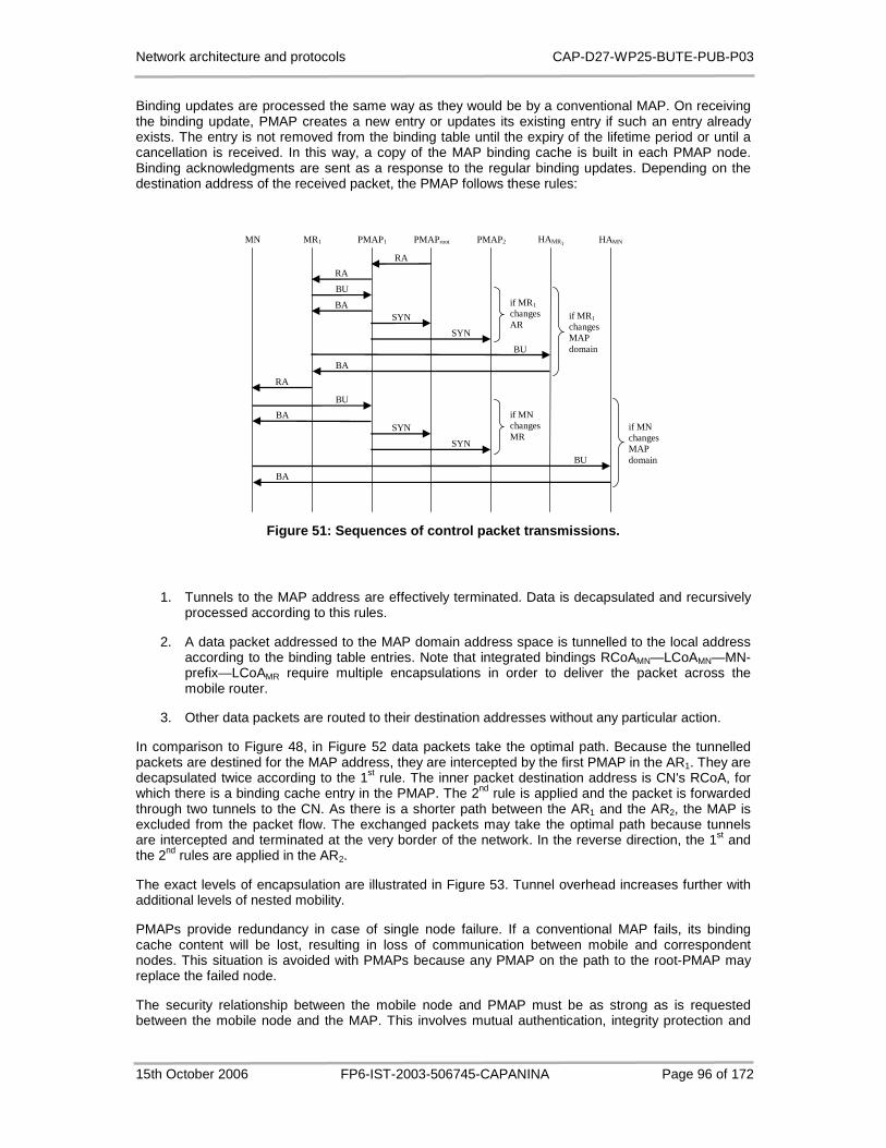
Network architecture and protocols CAP-D27-WP25-BUTE-PUB-P03
15th October 2006 FP6-IST-2003-506745-CAPANINA Page 96 of 172
Binding updates are processed the same way as they would be by a conventional MAP. On receiving the binding update, PMAP creates a new entry or updates its existing entry if such an entry already exists. The entry is not removed from the binding table until the expiry of the lifetime period or until a cancellation is received. In this way, a copy of the MAP binding cache is built in each PMAP node. Binding acknowledgments are sent as a response to the regular binding updates. Depending on the destination address of the received packet, the PMAP follows these rules:
MN MR1 PMAP1 PMAProot PMAP2 HAMR1 HAMN
RA
RA
BU
BA SYN
SYN
if MR1 changes AR
BU
BA
if MR1 changes MAP domain
RA
BU
BA SYN
SYN
if MN changes MR
BU
BA
if MN changes MAP domain
Figure 51: Sequences of control packet transmission s.
1. Tunnels to the MAP address are effectively terminated. Data is decapsulated and recursively processed according to this rules.
2. A data packet addressed to the MAP domain address space is tunnelled to the local address according to the binding table entries. Note that integrated bindings RCoAMN—LCoAMN—MN-prefix—LCoAMR require multiple encapsulations in order to deliver the packet across the mobile router.
3. Other data packets are routed to their destination addresses without any particular action.
In comparison to Figure 48, in Figure 52 data packets take the optimal path. Because the tunnelled packets are destined for the MAP address, they are intercepted by the first PMAP in the AR1. They are decapsulated twice according to the 1st rule. The inner packet destination address is CN's RCoA, for which there is a binding cache entry in the PMAP. The 2nd rule is applied and the packet is forwarded through two tunnels to the CN. As there is a shorter path between the AR1 and the AR2, the MAP is excluded from the packet flow. The exchanged packets may take the optimal path because tunnels are intercepted and terminated at the very border of the network. In the reverse direction, the 1st and the 2nd rules are applied in the AR2.
The exact levels of encapsulation are illustrated in Figure 53. Tunnel overhead increases further with additional levels of nested mobility.
PMAPs provide redundancy in case of single node failure. If a conventional MAP fails, its binding cache content will be lost, resulting in loss of communication between mobile and correspondent nodes. This situation is avoided with PMAPs because any PMAP on the path to the root-PMAP may replace the failed node.
The security relationship between the mobile node and PMAP must be as strong as is requested between the mobile node and the MAP. This involves mutual authentication, integrity protection and

Network architecture and protocols CAP-D27-WP25-BUTE-PUB-P03
15th October 2006 FP6-IST-2003-506745-CAPANINA Page 97 of 172
protection against replay attacks. The absence of protection may lead to malicious mobile nodes impersonating other legitimate ones or impersonating an MAP.
The MAP needs to ensure that a BU for a particular RCoA was issued by the same mobile node that established the security association (SA) for that RCoA. The security association can be established using any key establishment protocol. SA is not required in all PMAP nodes as opposed to the binding entry, which needs to be synchronized on every change. MNs and MRs need to send a binding update using the same SA on update lifetime expiry or when the node's local care-of-address changes. In the former case a binding update is processed by the PMAP that already holds the SA for the particular RCoA, while in the latter case the SA needs to be transferred to a new PMAP. The new PMAP could request the SA from the old PMAP providing that binding entries in PMAP nodes contain the information about the creator of the entry. Note that a request for a MR's SA implies a transfer of SAs for all MNs served by the MR.
HAMN
MN
Core Network
Nested Network
CN
HACN
HAMR1
MAP
AR2
MR2
AR1
MR1
root PMAP
PMAP PMAP
Figure 52: PMAP intra-domain data flow.
MN MR1 PMAP1 PMAP2 MR2 CN
IP in IP in IP
IP in IP
IP in IP
IP in IP in IP
IP in IP in IP
IP in IP
IP in IP in IP
IP in IP
Figure 53: Sequence of optimized data packet transm ission.
If PMAP solution is applied to the HAP network, backhaul links are excluded from the HAP-to-HAP communications. The exchanged packets take the optimal path. Packet flow after first-level route optimization is shown in Figure 54.
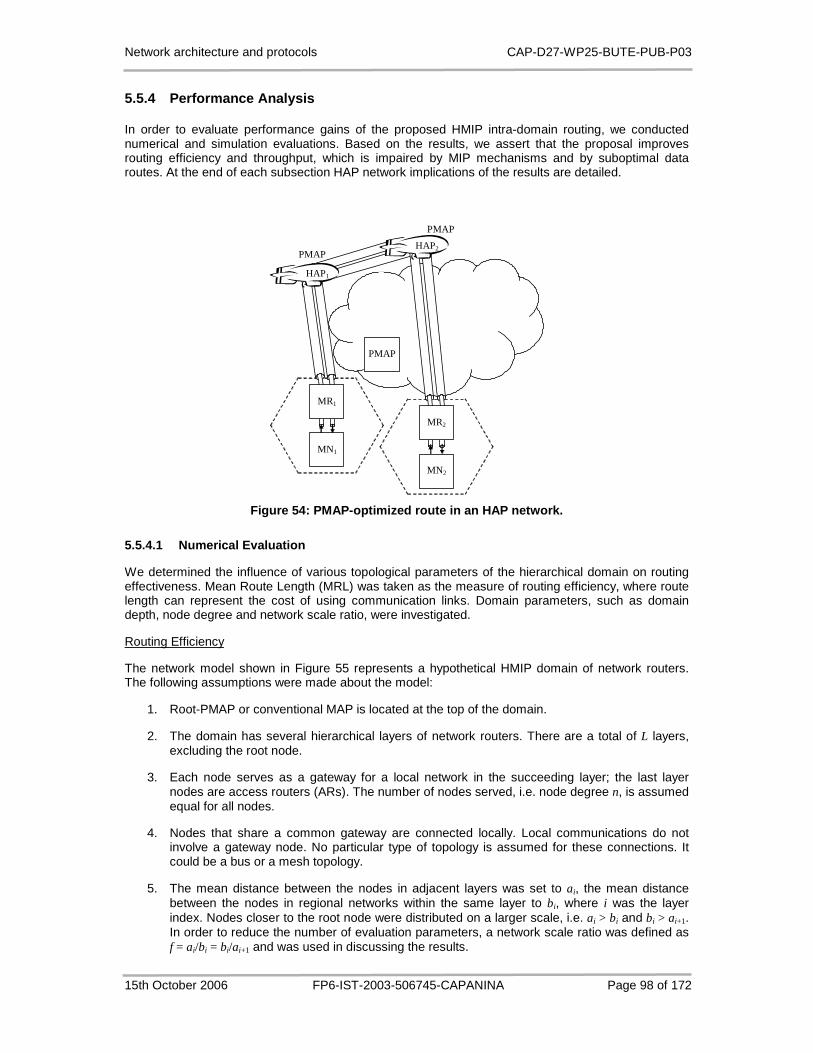
Network architecture and protocols CAP-D27-WP25-BUTE-PUB-P03
15th October 2006 FP6-IST-2003-506745-CAPANINA Page 98 of 172
5.5.4 Performance Analysis
In order to evaluate performance gains of the proposed HMIP intra-domain routing, we conducted numerical and simulation evaluations. Based on the results, we assert that the proposal improves routing efficiency and throughput, which is impaired by MIP mechanisms and by suboptimal data routes. At the end of each subsection HAP network implications of the results are detailed.
MN1
MN2
PMAP
HAP1
MR1
MR2
HAP2 PMAP
PMAP
Figure 54: PMAP-optimized route in an HAP network.
5.5.4.1 Numerical Evaluation
We determined the influence of various topological parameters of the hierarchical domain on routing effectiveness. Mean Route Length (MRL) was taken as the measure of routing efficiency, where route length can represent the cost of using communication links. Domain parameters, such as domain depth, node degree and network scale ratio, were investigated.
Routing Efficiency
The network model shown in Figure 55 represents a hypothetical HMIP domain of network routers. The following assumptions were made about the model:
1. Root-PMAP or conventional MAP is located at the top of the domain.
2. The domain has several hierarchical layers of network routers. There are a total of L layers, excluding the root node.
3. Each node serves as a gateway for a local network in the succeeding layer; the last layer nodes are access routers (ARs). The number of nodes served, i.e. node degree n, is assumed equal for all nodes.
4. Nodes that share a common gateway are connected locally. Local communications do not involve a gateway node. No particular type of topology is assumed for these connections. It could be a bus or a mesh topology.
5. The mean distance between the nodes in adjacent layers was set to ai, the mean distance between the nodes in regional networks within the same layer to bi, where i was the layer index. Nodes closer to the root node were distributed on a larger scale, i.e. ai > bi and bi > ai+1. In order to reduce the number of evaluation parameters, a network scale ratio was defined as f = ai/bi = bi/ai+1 and was used in discussing the results.
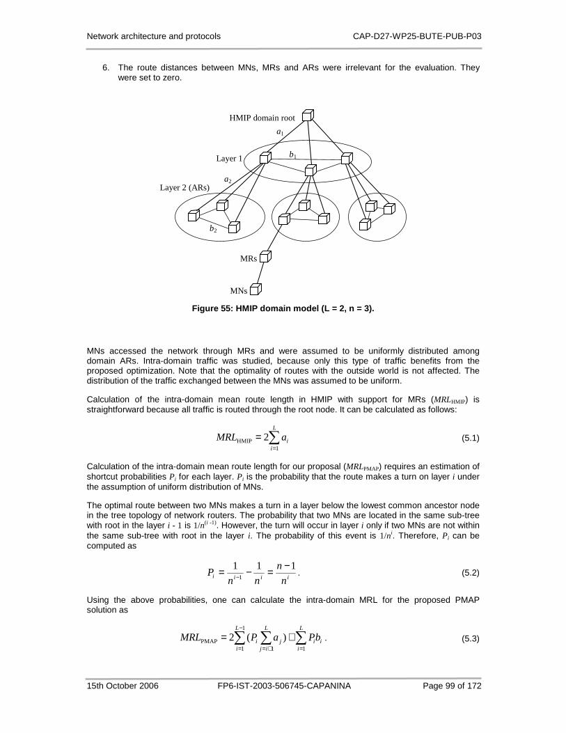
Network architecture and protocols CAP-D27-WP25-BUTE-PUB-P03
15th October 2006 FP6-IST-2003-506745-CAPANINA Page 99 of 172
6. The route distances between MNs, MRs and ARs were irrelevant for the evaluation. They were set to zero.
Layer 1
HMIP domain root
Layer 2 (ARs)
MRs
MNs
a1
b1
a2
b2
Figure 55: HMIP domain model ( L = 2, n = 3).
MNs accessed the network through MRs and were assumed to be uniformly distributed among domain ARs. Intra-domain traffic was studied, because only this type of traffic benefits from the proposed optimization. Note that the optimality of routes with the outside world is not affected. The distribution of the traffic exchanged between the MNs was assumed to be uniform.
Calculation of the intra-domain mean route length in HMIP with support for MRs (MRLHMIP) is straightforward because all traffic is routed through the root node. It can be calculated as follows:
∑=
=L
iiaMRL
1HMIP 2 (5.1)
Calculation of the intra-domain mean route length for our proposal (MRLPMAP) requires an estimation of shortcut probabilities Pi for each layer. Pi is the probability that the route makes a turn on layer i under the assumption of uniform distribution of MNs.
The optimal route between two MNs makes a turn in a layer below the lowest common ancestor node in the tree topology of network routers. The probability that two MNs are located in the same sub-tree with root in the layer i - 1 is 1/n(i -1). However, the turn will occur in layer i only if two MNs are not within the same sub-tree with root in the layer i. The probability of this event is 1/ni. Therefore, Pi can be computed as
iiiin
n
nnP
1111
−=−= − . (5.2)
Using the above probabilities, one can calculate the intra-domain MRL for the proposed PMAP solution as
∑ ∑ ∑−
= += =
+=1
1 1 1PMAP )(2
L
i
L
ij
L
iiiji bPaPMRL . (5.3)

Network architecture and protocols CAP-D27-WP25-BUTE-PUB-P03
15th October 2006 FP6-IST-2003-506745-CAPANINA Page 100 of 172
The first term is the contribution of vertical path segments, while the second is the mean distance of horizontal connections within regional networks.
Figure 56 shows the relationship between the depth of the domain L and the reduction of the mean route length resulting from applying our proposal. The reduction is calculated as (MRLHMIP - MRLPMAP)/MRLHMIP, presented as a percentage. The parameter n was set to 4. The reduction of mean route length decreases with the domain depth. In deeper domains there are shorter routes possible, however the probability of their occurrence is lower and the length of all routes increases, which explains why the reduction is larger for lower depths.
Figure 56: Reduction of MRL vs. domain depth ( n = 4).
As expected, network scale ratio has a significant influence on the effectiveness of intra-domain optimization. The reduction of mean route length is larger in networks with larger f, as seen in Figure 57.
Figure 57: Reduction of MRL vs. network scale ratio (n = 4).
The influence of node degree on the MRL reduction is demonstrated in Figure 58. Larger reductions are achieved in narrower domains, i.e. domains with smaller n. The reduction curves approach asymptotic values. The decrease in reduction is particularly noticeable for node degrees up to 10. The asymptotic value can be computed as the limit of the MRL reduction function as n approaches infinity.

Network architecture and protocols CAP-D27-WP25-BUTE-PUB-P03
15th October 2006 FP6-IST-2003-506745-CAPANINA Page 101 of 172
In Figure 58, the asymptotic values are approximately 57% for the upper curve and 40% for the lower curve.
Figure 58: Reduction of MRL vs. node degree ( L = 3).
PMAP Synchronization
PMAP extension of HMIP requires BU messages to be multicast to a group of nodes instead of being forwarded only to the domain root node, which results in increasing the number of control messages within the hierarchical domain. We evaluate the increase of control messages numerically and propose additional improvement to the synchronization procedure in order to keep the synchronization load as low as possible.
Each BU received by an AR triggers the synchronization procedure. In case of PIM-DM as underlying multicast protocol, a shortest path tree is used to deliver synchronization messages to all PMAPs. Therefore, the number of exchanged messages using the model in Figure 55 equals
∑=
L
i
in1
, (5.4)
which is actually the total number of nodes in HMIP domain reduced by one, as opposed to 2L messages required in domains without PMAP support. Note that BUs sent to the MAP must be acknowledged.
Obviously, the intra-domain route optimization capability comes at the price of increased signalling. When we consider the increase in number of control messages, we have to take into account the following facts:
1. BUs to the MAP highly depend on the moving patterns of MNs and MRs. A MR sends a BU on every AR change, whereas MNs served by the MR send BUs only on MAP domain change. There is an additional BU that needs to be sent if a MN changes MR.
2. It is generally not advised to deploy an HMIP domain with a large L. The size and the depth of the MAP domain should not be so large that mobile nodes could become too far from the MAP and loose some benefits of route optimization to nodes in global network.
A solution to reduce the number of synchronization messages can be based on the following observation. Let the optimal route between two ARs make a turn in layer i with respect to the model in Figure 55. If we allow PMAP functionality in layer i, there is no need to distribute bindings all the way

Network architecture and protocols CAP-D27-WP25-BUTE-PUB-P03
15th October 2006 FP6-IST-2003-506745-CAPANINA Page 102 of 172
from one AR to another. It is sufficient to keep binding cache entries synchronized in layer i only. An AR without matching binding entry will pass a packet toward the root PMAP. Consequently, a PMAP node in layer i will intercept the packet and the route optimality will not be affected.
In order to achieve limited distribution of synchronization messages, PMAPs should support the following protocol. Upon the receipt of a synchronization message, a PMAP forwards the message to the router higher in the domain tree. Further, the PMAP should multicast the synchronization message to the local nodes on the same layer. If we apply the method described above on our domain model, only 6 messages per BU are required instead of 12. More formally, the number of synchronization messages per BU equals Ln, which is a notable improvement in comparison to (4).
HAP Network Application
When the root of a hierarchical domain in the HAP network resides on the ground, the number of levels L is 1. Due to differences in the underlying transport technologies, i.e. optical versus radio transmission, and the fact that mean distance reflects the cost of communication links, a1 exceeds b1 by even more than one order of magnitude, i.e. f > 10. It is assumed that all HAPs have a backhaul connection with the ground nodes. Consequently, the node degree n is equal to the number of HAPs. Cost reduction, as defined above, is significant. It can be evaluated as
)2
11(100)
2
11(100
fnf
n −≈−− . (5.5)
For example, in case of f = 10, the cost reduction amounts to 95%.
5.5.4.2 Simulation Evaluation
In addition to more efficient utilization of network resources, intra-domain optimization improves TCP flow performance. This is due to the fact that data on shorter routes usually experience less delay. Simulations were performed in order to provide quantitative results.
It is well-known that TCP performance suffers on the longer RTT (Round Trip Time) connections because of the TCP window-based transmission algorithm which, being triggered by acknowledgement arrivals, depends on network delays [72]. Furthermore, the optimal path between two mobile nodes cannot be used at once. Binding updates must be exchanged in order to establish an optimized route. Note that the return routability procedure precedes each binding update, incurring additional delay. However, mobile nodes are expected to send data from the very beginning of the connection, which causes some data to experience a longer RTT.
We studied TCP performance for various communication scenarios using the ns-2 simulator [20]. A series of simulation experiments were performed for the environment with no second-level optimization, for the HMIP based optimization, and for the PMAP extended HMIP scenario. Simulation network topology was chosen to represent a network architecture with a single layer of network routers according to the model in Figure 55. Results for multiple layer architectures can be deduced using the conclusions on the MRL reduction.
The network topology considered in the ns-2 simulation runs is shown in Figure 59. This topology depicts a simplistic version of a network topology. There are two access links - from the MR1 to the HAP1 and from the MR2 to the HAP2, a link between the HAPs, a MAP and a link with the global network, where home agents are expected to be located. A 50 ms link delay was selected for communication with the global network as opposed to 2.5 ms delay for other links. A TCP agent was attached to the MR1, while the TCP sink was positioned in the MR2's network. A persistent FTP file transfer was set up. The maximum size of a packet that the TCP agent could generate was 1 Kbyte.
We define RTTL as the round trip time of the path between two mobile nodes that traverses the global network, and RTTS as the RTT of the shortest path possible. It is assumed that the MN1, as initiator of the communication, triggers path optimization in parallel with the first data being sent. In the best case scenario, the delay between the start of the communication and the time when MN2 starts using MN1's RCoA can be approximated as 1.5 RTTL. This time is needed for completion of the return routability procedure and for the binding update message to be received by the MN2 [57]. On the other hand, the MN2 initiates another return routability procedure and sends its own binding update message to the
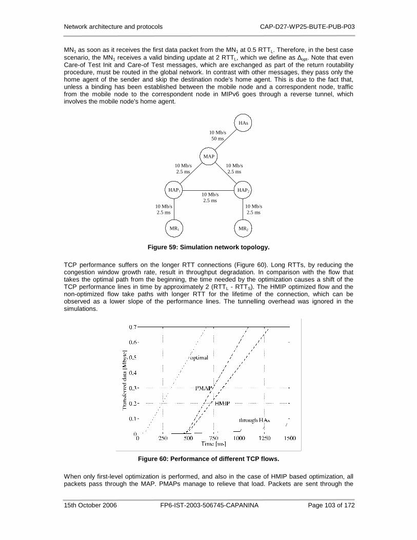
Network architecture and protocols CAP-D27-WP25-BUTE-PUB-P03
15th October 2006 FP6-IST-2003-506745-CAPANINA Page 103 of 172
MN1 as soon as it receives the first data packet from the MN1 at 0.5 RTTL. Therefore, in the best case scenario, the MN1 receives a valid binding update at 2 RTTL, which we define as ∆opt. Note that even Care-of Test Init and Care-of Test messages, which are exchanged as part of the return routability procedure, must be routed in the global network. In contrast with other messages, they pass only the home agent of the sender and skip the destination node's home agent. This is due to the fact that, unless a binding has been established between the mobile node and a correspondent node, traffic from the mobile node to the correspondent node in MIPv6 goes through a reverse tunnel, which involves the mobile node's home agent.
MAP
10 Mb/s 2.5 ms
10 Mb/s 50 ms
MR1
HAP1 HAP2
HAs
MR2
10 Mb/s 2.5 ms
10 Mb/s 2.5 ms
10 Mb/s 2.5 ms
10 Mb/s 2.5 ms
Figure 59: Simulation network topology.
TCP performance suffers on the longer RTT connections (Figure 60). Long RTTs, by reducing the congestion window growth rate, result in throughput degradation. In comparison with the flow that takes the optimal path from the beginning, the time needed by the optimization causes a shift of the TCP performance lines in time by approximately 2 (RTTL - RTTS). The HMIP optimized flow and the non-optimized flow take paths with longer RTT for the lifetime of the connection, which can be observed as a lower slope of the performance lines. The tunnelling overhead was ignored in the simulations.
Figure 60: Performance of different TCP flows.
When only first-level optimization is performed, and also in the case of HMIP based optimization, all packets pass through the MAP. PMAPs manage to relieve that load. Packets are sent through the

Network architecture and protocols CAP-D27-WP25-BUTE-PUB-P03
15th October 2006 FP6-IST-2003-506745-CAPANINA Page 104 of 172
MAP only during the ∆opt time period. During this time the packets are routed in the global network in all communication scenarios. The slow start congestion avoidance algorithm limits the amount of data being injected into the network by a TCP sender during ∆opt interval, as seen in Figure 60. Note that the amount of data sent into the global network in the case of UDP flows is larger, since there is no acknowledgement mechanism.
5.5.5 Proxy Home Agents
Inter-domain route optimization issue may be solved even if HMIP-based route optimization for mobile routers is not implemented in the HAP network. Similar proxy functionality may be applied in a form of Proxy Home Agents (PHAs). However, this solution requires extensions in mobile routers that are expected to roam the HAP network. Optimal inter-platform routes may be achieved even when mobility management for mobile routers does not include support for route optimization. Proxy Home Agents adopt an idea of distributing routing information in selected parts of the network in order to speed up route convergence to its optimal path. In the following we provide a short description of PHA functionality.
Proxy Home Agent functionality should be implemented in HAP nodes. The PHAs perform similar tasks as home agents in home networks. The PHAs are used only by mobile routers that roam in the HAP network and are interconnected in a group.
A mechanism allows a mobile router to discover the nearest PHA on a visited link. This may be achieved in a similar way as mobile nodes discover MAP node in HMIP, where a new option is introduced in router advertisements. In addition to sending a registration request to its HA, mobile router would register, i.e. send a binding update, with nearest PHA, which would in turn multicast the registration request to the PHA group.
Each PHA maintains a binding cache. Upon receiving of the binding update, PHA creates a new entry for the mobile router or updates its existing entry, if such an entry already exists. The entry binds the MR's home network prefix with its CoA. The entry is not removed from the binding cache until the expiration of the lifetime period or until a cancellation is received.
An HAP intercepts all packets that are addressed to the mobile router's network while it is serving as the PHA for the MR. Like the HA, the PHA establishes a tunnel to the MR and forwards intercepted packets.
The MR continues to notify, i.e. sends binding updates to the advertised PHA, until it stays within the HAP coverage. As soon as the MR leaves the HAP network it de-registers with the last known PHA and withdraws any further notifications. The cancellation is, like other messages to the PHA, multicast to the PHA group.
Suppose that both a CN and a MN access the network through the mobile routers that are roaming in an HAP network. The first few packets from the CN to the MN are routed through the MN's HA. After the first-level route optimization, the CN is notified about the MN's CoA, which is within the MR's home domain. Further packets from the CN to the MN are destined to the MR's home address and, therefore, intercepted by the PHA on the access HAP and tunnelled to the MR's CoA. Backhaul links and the MR's HA are excluded from the packet flow between these two nodes. The exchanged packets take optimal path because they are intercepted at the very border of the network. Existing IP routing mechanism forwards the packets to the MR's current location based on the knowledge of the network topology, which includes the knowledge of the alternative routes.
The proposed mechanism was evaluated in terms of backhaul link utilization and flow performance. Only HAP-to-HAP communication was considered, representing the only segment benefiting from the PHA mechanism. TCP traffic has been examined by means of the ns-2 simulator. Series of simulation experiments were performed in probing different communication scenarios. Simulations were performed for the environment with no second-level optimization, for the HMIP based optimization with MAP placed on the ground, and for the PHA based optimization. Results resemble that from the previous section, with slight differences in actual timing (Figure 60).
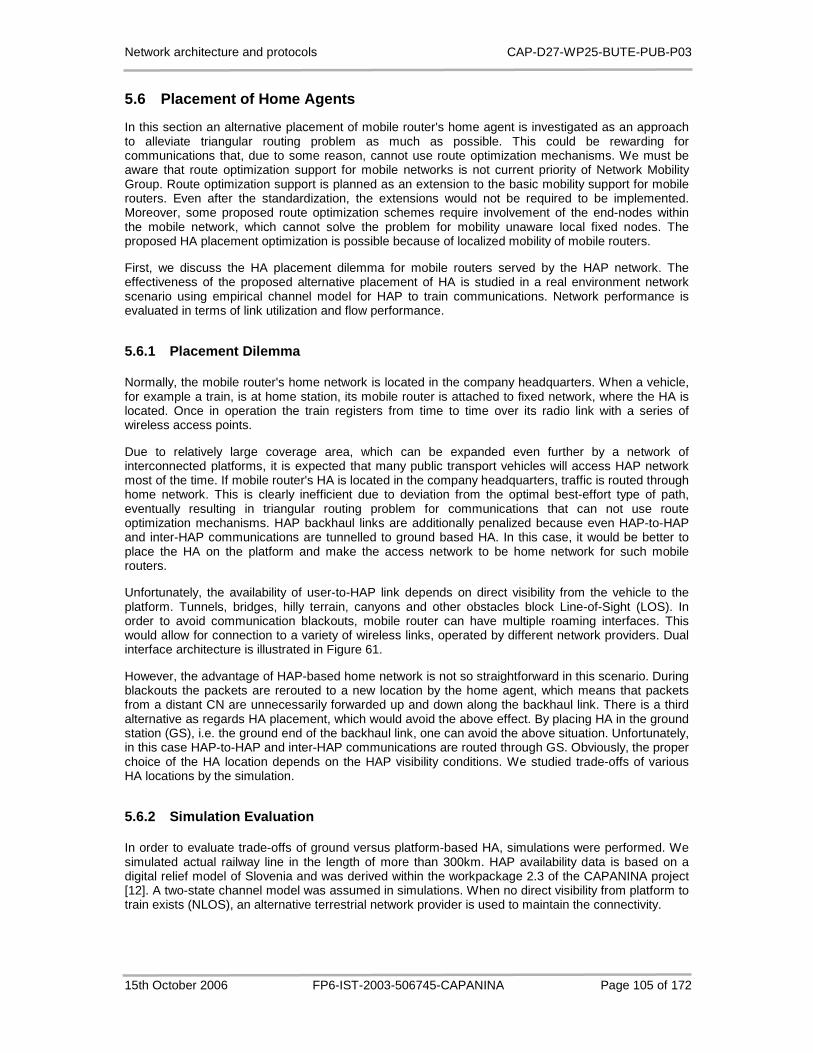
Network architecture and protocols CAP-D27-WP25-BUTE-PUB-P03
15th October 2006 FP6-IST-2003-506745-CAPANINA Page 105 of 172
5.6 Placement of Home Agents
In this section an alternative placement of mobile router's home agent is investigated as an approach to alleviate triangular routing problem as much as possible. This could be rewarding for communications that, due to some reason, cannot use route optimization mechanisms. We must be aware that route optimization support for mobile networks is not current priority of Network Mobility Group. Route optimization support is planned as an extension to the basic mobility support for mobile routers. Even after the standardization, the extensions would not be required to be implemented. Moreover, some proposed route optimization schemes require involvement of the end-nodes within the mobile network, which cannot solve the problem for mobility unaware local fixed nodes. The proposed HA placement optimization is possible because of localized mobility of mobile routers.
First, we discuss the HA placement dilemma for mobile routers served by the HAP network. The effectiveness of the proposed alternative placement of HA is studied in a real environment network scenario using empirical channel model for HAP to train communications. Network performance is evaluated in terms of link utilization and flow performance.
5.6.1 Placement Dilemma
Normally, the mobile router's home network is located in the company headquarters. When a vehicle, for example a train, is at home station, its mobile router is attached to fixed network, where the HA is located. Once in operation the train registers from time to time over its radio link with a series of wireless access points.
Due to relatively large coverage area, which can be expanded even further by a network of interconnected platforms, it is expected that many public transport vehicles will access HAP network most of the time. If mobile router's HA is located in the company headquarters, traffic is routed through home network. This is clearly inefficient due to deviation from the optimal best-effort type of path, eventually resulting in triangular routing problem for communications that can not use route optimization mechanisms. HAP backhaul links are additionally penalized because even HAP-to-HAP and inter-HAP communications are tunnelled to ground based HA. In this case, it would be better to place the HA on the platform and make the access network to be home network for such mobile routers.
Unfortunately, the availability of user-to-HAP link depends on direct visibility from the vehicle to the platform. Tunnels, bridges, hilly terrain, canyons and other obstacles block Line-of-Sight (LOS). In order to avoid communication blackouts, mobile router can have multiple roaming interfaces. This would allow for connection to a variety of wireless links, operated by different network providers. Dual interface architecture is illustrated in Figure 61.
However, the advantage of HAP-based home network is not so straightforward in this scenario. During blackouts the packets are rerouted to a new location by the home agent, which means that packets from a distant CN are unnecessarily forwarded up and down along the backhaul link. There is a third alternative as regards HA placement, which would avoid the above effect. By placing HA in the ground station (GS), i.e. the ground end of the backhaul link, one can avoid the above situation. Unfortunately, in this case HAP-to-HAP and inter-HAP communications are routed through GS. Obviously, the proper choice of the HA location depends on the HAP visibility conditions. We studied trade-offs of various HA locations by the simulation.
5.6.2 Simulation Evaluation
In order to evaluate trade-offs of ground versus platform-based HA, simulations were performed. We simulated actual railway line in the length of more than 300km. HAP availability data is based on a digital relief model of Slovenia and was derived within the workpackage 2.3 of the CAPANINA project [12]. A two-state channel model was assumed in simulations. When no direct visibility from platform to train exists (NLOS), an alternative terrestrial network provider is used to maintain the connectivity.

Network architecture and protocols CAP-D27-WP25-BUTE-PUB-P03
15th October 2006 FP6-IST-2003-506745-CAPANINA Page 106 of 172
Figure 61: Dual interface architecture for MIP hand over during NLOS conditions.
5.6.2.1 Simulation Tool
The actual simulations were performed using the OPNET Modeler [73], which is a discrete event based simulation tool. Built-in models were adapted to support the mobility scenario with mobile routers due to lack of efficient MIP model for targeted wireless environment. Wired models were extended with expected handoff behaviour in wireless settings.
We took into account the discarded packets due to handoff latency. The exact moments of reroute actions and packet discarding intervals were calculated in advance with respect to the LOS conditions and handoff procedures. Actual tunnel was setup between the HA and the MR.
A persistent FTP file transfer was established with a single CN as a sender and a single MN as a receiver. Since FTP uses TCP transport protocol, we were actually observing the TCP performance. In the following, a small time interval in the LOS input data is analyzed in order to observe the effects of handoff performance and the influence of LOS/NLOS conditions with sufficient precision.
5.6.2.2 Results
Several simulation scenarios were compared. They were defined with respect to the placement of the HA, which can be located in the global network (SGN) (i.e. company headquarters), in the ground station (SGS) or on the platform (SHAP). In each of the scenarios, two locations of the CN were considered. The CN was placed either in the global network or in the HAP network. Note that the MN always resided within the mobile network.
Figure 62 shows selected delays and bandwidths for the SGN scenario with the CN in the global network. An average delay of 25 ms was set in the global network as opposed to 2.5 ms delay for wireless links. The delay between the WLAN base station and the core network was assumed to be negligible. The backhaul link between the HAP and the GS is expected to be a bottleneck link. We configured link background traffic of various intensities in order to simulate the bottleneck conditions.

Network architecture and protocols CAP-D27-WP25-BUTE-PUB-P03
15th October 2006 FP6-IST-2003-506745-CAPANINA Page 107 of 172
Figure 62: Simulation network topology with CN in g lobal network.
First we discuss TCP performance for the scenarios with the CN in the global network. Figure 63 depicts data transfer rate for the three scenarios with no background traffic on the backhaul link. The SGN curve has the lowest slope, which is mainly due to delay in the global network. If the HA is located on the HAP, performance improves significantly even though the route is not optimal during the NLOS period. This is because of low delay between the terrestrial wireless network and the HAP ground station, which are geographically nearby. However, during the NLOS conditions backhaul link is still being used in both uplink and downlink direction. This could potentially lead to link congestion, as it is shown in the following. Therefore, the best performance is achieved with the HA in the GS. The transfer rate is slightly higher, comparing it to the SHAP scenario, because of more optimal routes. Furthermore, the backhaul link load is removed during the NLOS conditions.
Figure 63: TCP performance (CN in global network, b ackground traffic at 0%).
If background traffic on the backhaul link increases, the bottleneck effect increases as well. Delays on the backhaul link get higher, which has an impact on the TCP performance. This is particularly
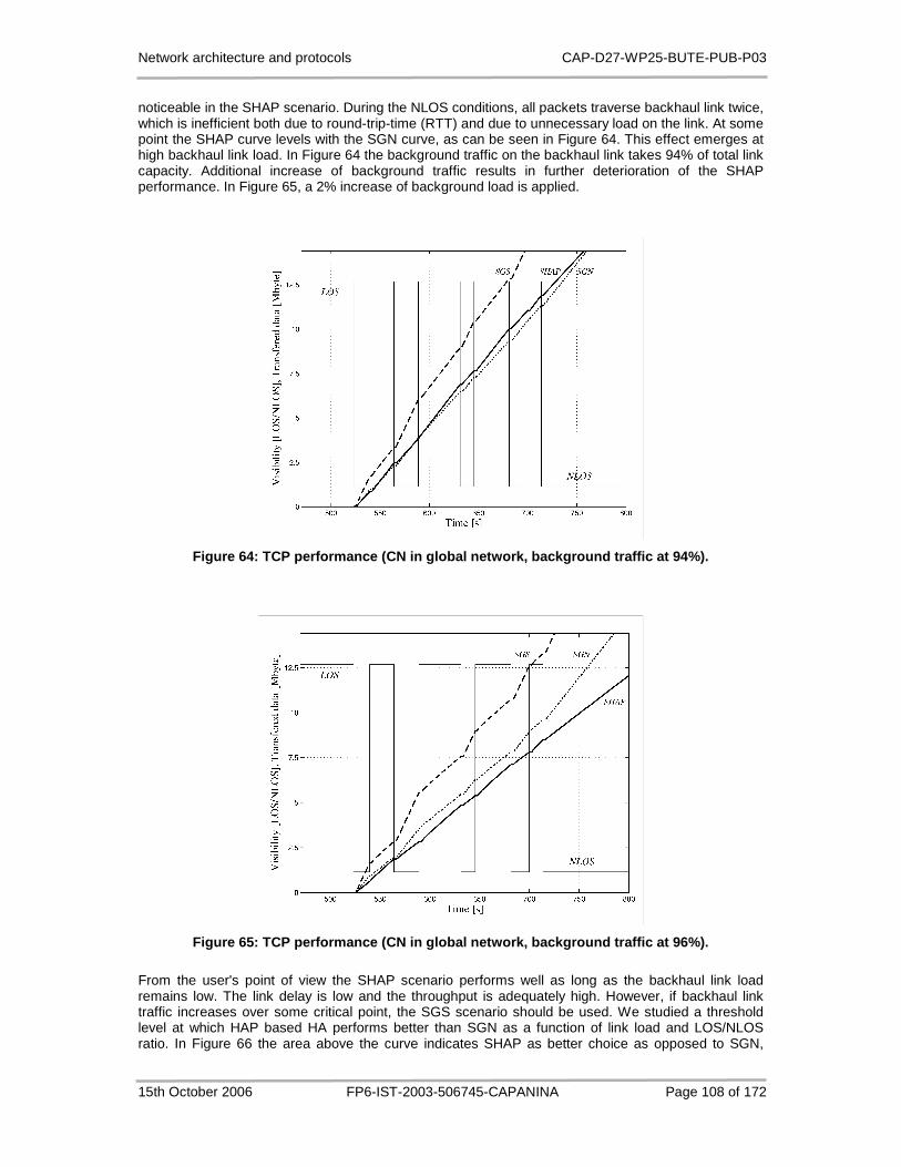
Network architecture and protocols CAP-D27-WP25-BUTE-PUB-P03
15th October 2006 FP6-IST-2003-506745-CAPANINA Page 108 of 172
noticeable in the SHAP scenario. During the NLOS conditions, all packets traverse backhaul link twice, which is inefficient both due to round-trip-time (RTT) and due to unnecessary load on the link. At some point the SHAP curve levels with the SGN curve, as can be seen in Figure 64. This effect emerges at high backhaul link load. In Figure 64 the background traffic on the backhaul link takes 94% of total link capacity. Additional increase of background traffic results in further deterioration of the SHAP performance. In Figure 65, a 2% increase of background load is applied.
Figure 64: TCP performance (CN in global network, b ackground traffic at 94%).
Figure 65: TCP performance (CN in global network, b ackground traffic at 96%).
From the user's point of view the SHAP scenario performs well as long as the backhaul link load remains low. The link delay is low and the throughput is adequately high. However, if backhaul link traffic increases over some critical point, the SGS scenario should be used. We studied a threshold level at which HAP based HA performs better than SGN as a function of link load and LOS/NLOS ratio. In Figure 66 the area above the curve indicates SHAP as better choice as opposed to SGN,
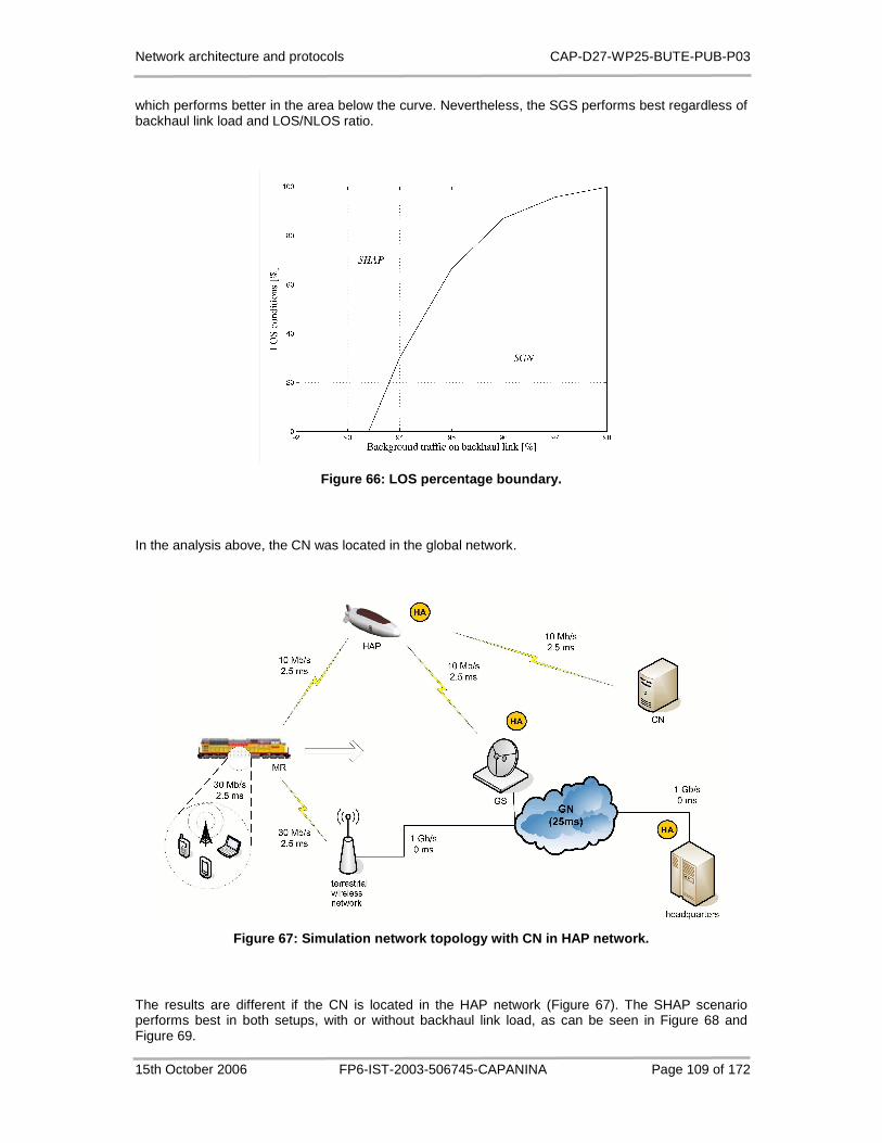
Network architecture and protocols CAP-D27-WP25-BUTE-PUB-P03
15th October 2006 FP6-IST-2003-506745-CAPANINA Page 109 of 172
which performs better in the area below the curve. Nevertheless, the SGS performs best regardless of backhaul link load and LOS/NLOS ratio.
Figure 66: LOS percentage boundary.
In the analysis above, the CN was located in the global network.
Figure 67: Simulation network topology with CN in H AP network.
The results are different if the CN is located in the HAP network (Figure 67). The SHAP scenario performs best in both setups, with or without backhaul link load, as can be seen in Figure 68 and Figure 69.
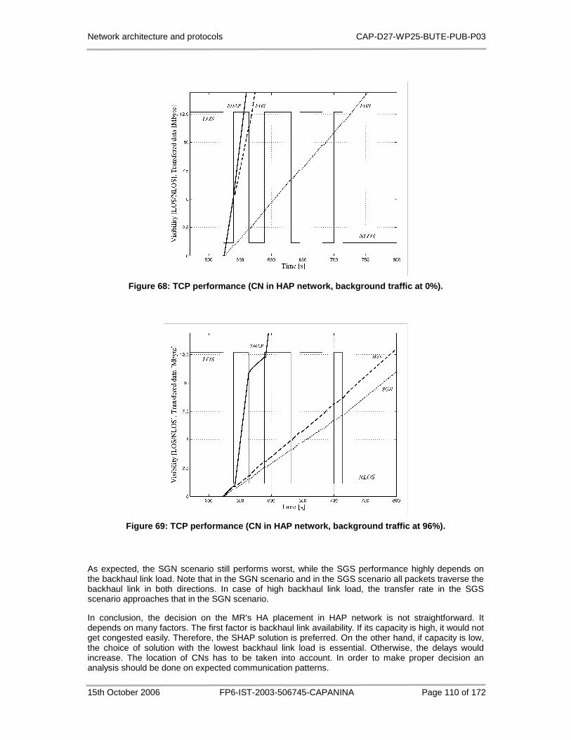
Network architecture and protocols CAP-D27-WP25-BUTE-PUB-P03
15th October 2006 FP6-IST-2003-506745-CAPANINA Page 110 of 172
Figure 68: TCP performance (CN in HAP network, back ground traffic at 0%).
Figure 69: TCP performance (CN in HAP network, back ground traffic at 96%).
As expected, the SGN scenario still performs worst, while the SGS performance highly depends on the backhaul link load. Note that in the SGN scenario and in the SGS scenario all packets traverse the backhaul link in both directions. In case of high backhaul link load, the transfer rate in the SGS scenario approaches that in the SGN scenario.
In conclusion, the decision on the MR's HA placement in HAP network is not straightforward. It depends on many factors. The first factor is backhaul link availability. If its capacity is high, it would not get congested easily. Therefore, the SHAP solution is preferred. On the other hand, if capacity is low, the choice of solution with the lowest backhaul link load is essential. Otherwise, the delays would increase. The location of CNs has to be taken into account. In order to make proper decision an analysis should be done on expected communication patterns.

Network architecture and protocols CAP-D27-WP25-BUTE-PUB-P03
15th October 2006 FP6-IST-2003-506745-CAPANINA Page 111 of 172
The findings of our simulations are summarized in Table 11. For every combination of scenario and criteria, HA locations are numerated in order of preference.
Table 11: Optimal HA placement in terms of throughp ut and backhaul link loads.
CN IN GLOBAL NETWORK CN IN HAP NETWORK
Throughput 1. HA in the ground station
2. HA on HAP (if backhaul link load is low)
3. HA in the global network (if backhaul link load is low)
1. HA on HAP
2. HA in the ground station
3. HA in the global network
Backhaul link load 1. HA either in the ground station or in the global network
2. HA on HAP
1. HA on HAP
2. HA either in the ground station or in the global network
5.7 Multihoming Support
If only one HA is supported per MR, choosing its optimal location depends on many factors, as seen in previous section. However, there is a possibility to have more than one HA per MR. That can be achieved by having multihomed mobile network. It is expected that providing a permanent access to mobile networks, such as those on trains, would require the use of several interfaces and technologies, which supports the idea of multihomed mobile networks.
NEMO basic support does not prevent mobile routers to be multihomed. There are many definitions of multihoming. A multihomed router is a router with multiple HAs, generally one per egress interface. According to [74], the MR is multihomed if either multiple prefixes are advertised on visited link or the MR is equipped with multiple interfaces, while by [75] a host is said to be multihomed if it has several IP addresses to choose between. In general, a multihomed router may have many HAs, more than one home address as well as many care-of-addresses. It can have one or more interfaces. Mobile network is multihomed in case of hosting a multihomed MR or multiple classical MRs.
The consequence of having multiple home agents is the existence of multiple bi-directional tunnels between the mobile network and its HAs. This may eventually result into multiple prefixes being advertised to the mobile nodes. Currently, there are neither requirements nor a standardized protocol defining how to use several tunnels inside a MR.
Main advantages of having multihomed routers in HAP networks are the following:
1. Providing connection redundancy and fault-recovery. This can be used as a way to deal with NLOS intervals, which would result in permanent and ubiquitous access.
2. Smoother handoff between HAP and terrestrial wireless systems.
3. Gains in terms of optimal routes.
4. Load sharing and load balancing between multiple HAPs or between HAP and terrestrial access network.
In the following we identify multihoming configuration that best suits to HAP network, and point out some related issues critical to deployment of multihoming in HAP networks.

Network architecture and protocols CAP-D27-WP25-BUTE-PUB-P03
15th October 2006 FP6-IST-2003-506745-CAPANINA Page 112 of 172
5.7.1 Configuration Taxonomy
Taxonomy (iface, HoA, CoA) is suggested in [76] to identify different possible multihoming configurations for end-nodes, where iface stands for the number of interfaces, HoA represents the number of home addresses and CoA the number of care-of-addresses. In case of mobile networks the use of taxonomy (MR, HA, MNP) is suggested in [74], where MR indicates the number of MRs, HA indicates the number of HAs associated with the entire mobile network and MNP the number of prefixes advertised in the mobile network. Here we suggest the use of (MR, HA, MNP, iface, CoA) taxonomy to fully describe a certain NEMO configuration among all possibilities. The HAP important 5-tuples are:
(1,1,1,N,1): This is a classical setup with a single MR and one HA, advertising a single prefix to the end-nodes. Multiple (N) interfaces are available, but only one CoA may be active at any given moment. In the HAP network, this configuration can be used as a baseline solution to the NLOS problem. The configuration does not solve excessive use of backhaul link due to inefficient routing through MR’s HA, and the dilemma, where to put the HA still remains. Some kind of priority scheme should be followed by the MR in tunnel selection for the outbound traffic, based on triggers from the link layer. Inbound traffic is less protected from loss due to HA’s inability to establish the current state of wireless segment in each tunnel. Having at least one bi-directional tunnel available at any point in time between the mobile network and the fixed network is required but not sufficient condition for transparent communication. Fast acquisition of tunnel state information is equally important to prevent loss of data. Both the inbound and outbound traffic must be diverted over another bi-directional tunnel once NLOS conditions occur.
(1,1,N,N,N): Multiple advertised prefixes allow end-nodes being multihomed; however, that does not mitigate problems due to HAP unavailability. Connections must be torn down and established from a scratch because the transport layer in the end-nodes does not allow dynamic address change. Stream Control Transmission Protocol (SCTP) is an exception. Due to multihoming capabilities at transport layer SCTP may be able to continue without disruption. Overall, advertising multiple prefixes in mobile network, e.g. one per MR’s egress interface, brings no particular advantage to the train-to-HAP scenario.
(1,N,1,N,N): In this configuration multiple HAs exist to support a single MR. Nodes served by the MR are not aware of multihoming as they see only one prefix. The HAs may be located in different parts of the network; however, they should advertise a route to the same prefix. Due to lack of route aggregation in neighbouring routers this may lead to routing table growth in part of global routing infrastructure. The configuration is advantageous in the HAP network because it solves backhaul link issue. If we put one HA on the platform and the other on the ground, inter-HAP traffic is automatically routed through the platform-based HA, while the ground-based HA intercepts global traffic. As a consequence, near optimal routes are used while the MR roams close to one of the HAs. In order to support smooth handover between the agents due to NLOS periods, the coordination between the two HAs is required. There are a few inter home agent protocols proposed, the HAHA protocol is one of them [77].
(N,1,1,N,N): A train is composed of multiple cars, which are dynamically added or removed according to the needs. Therefore, it is possible that multiple MRs will be attached together in a single mobile network. Configuration (N,1,1,N,N) assumes multiple routers that serve a single prefix. Common HA is provided for all MRs. Each MR may be itself multihomed using different egress interfaces. A set-up with some MRs connected to an HAP and some to a terrestrial wireless system is less likely because it would be difficult to guarantee train modularity unless each train car would contain both type of routers.
(N,1,N,N,N): This configuration has advantage over (N,1,1,N,N) due to multiple prefixes being advertised within the mobile network. Multiple prefixes may be advertised by all MRs or, more likely, different prefixes are advertised by different MRs, in which case train modularity may be easily supported. MRs can still be multihomed, which may provide route optimality.
The remaining more general multihomed configurations do not bring additional benefits to the mobile networks accessing HAPs.
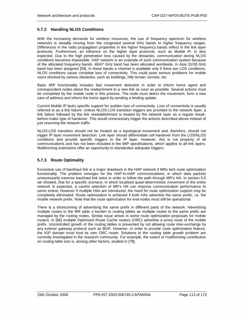
Network architecture and protocols CAP-D27-WP25-BUTE-PUB-P03
15th October 2006 FP6-IST-2003-506745-CAPANINA Page 113 of 172
5.7.2 Handling NLOS Conditions
With the increasing demands for wireless resources, the use of frequency spectrum for wireless networks is steadily moving from the congested several GHz bands to higher frequency ranges. Differences in the radio propagation properties in the higher frequency bands reflect in the link layer protocols. Furthermore, an influence on the higher layer protocols, such as Mobile IP, is also expected. Due to the high penetration loss caused by the obstacles, communication during NLOS conditions becomes impossible. HAP network is an example of such communication system because of the allocated frequency bands. 48/47 GHz band has been allocated worldwide. In Asia 31/28 GHz band has been assigned [59]. In these bands a channel is available only if there are LOS conditions. NLOS conditions cause complete loss of connectivity. This could pose serious problems for mobile users blocked by various obstacles, such as buildings, hilly terrain, tunnels, etc.
Basic MIP functionality includes fast movement detection in order to inform home agent and correspondent nodes about the reattachment to a new link as soon as possible. Several actions must be completed by the mobile node in this process. The node must detect the movement, form a new care-of address and inform the home agent by sending a binding update.
Current Mobile IP lacks specific support for sudden loss of connectivity. Loss of connectivity is usually referred to as a link failure. Unless NLOS-LOS transition triggers are provided to the network layer, a link failure followed by the link reestablishment is treated by the network layer as a regular break-before-make type of handover. This would unnecessary trigger the actions described above instead of just resuming the network traffic.
NLOS-LOS transition should not be treated as a topological movement and, therefore, should not trigger IP layer movement detection. Link layer should differentiate cell handover from the LOS/NLOS conditions and provide specific triggers to the IP layer. However, this is not property of all communications and has not been included in the MIP specifications, which applies to all link layers. Multihoming extensions offer an opportunity to standardise adequate triggers.
5.7.3 Route Optimality
Excessive use of backhaul link is a major drawback in the HAP network if MRs lack route optimization functionality. The problem emerges for the HAP-to-HAP communications, in which data packets unnecessarily traverse backhaul link twice in order to follow the path through MR’s HA. In section 5.6 we showed, that for a specific scenario, in which localized quasi-deterministic movement of the entire network is expected, a careful selection of MR’s HA can improve communication performance to some extent. However if multiple HAs are introduced, the need for route optimization support may be completely eliminated. Route optimization is achieved if both HAs advertise the same prefix, i.e. the mobile network prefix. Note that the route optimization for end-nodes must still be operational.
There is a shortcoming of advertising the same prefix in different parts of the network. Advertising multiple routes to the MR adds a burden to routing tables as multiple routes to the same prefix are managed by the routing nodes. Similar issue arises in some route optimization proposals for mobile routers. In [66] multiple Optimized Route Cache routers (ORC) advertise a proxy route of the mobile prefix. Uncontrolled growth of the routing tables is prevented by not allowing route inter-exchange by any exterior gateway protocol such as BGP. However, in order to provide route optimization feature, the IGP domain must host its own ORC router. Solutions to the routing table growth problem are currently investigated in the research community. For example, the extent of multihoming contribution on routing table size is, among other factors, studied in [78].

Network architecture and protocols CAP-D27-WP25-BUTE-PUB-P03
15th October 2006 FP6-IST-2003-506745-CAPANINA Page 114 of 172
5.7.4 Simulation Evaluation
In order to evaluate trade-offs of standard MIP versus multihomed MIP, simulations were performed. To simulate the variable channel conditions, we used the channel model, described in section 5.6. When no direct visibility from platform to train exists (NLOS), an alternative terrestrial network provider is used to maintain connectivity.
Figure 70 depicts the network topology used in simulations. In order to achieve optimal routes for all CN’s locations, two HA locations are sufficient, i.e. on the HAP and in the ground station (GS), which is topologically close to the GN. The MN is located within the mobile network. The backhaul link between the HAP and the GS is expected to be a bottleneck link. Therefore, the utilization of the backhaul link was observed in particular.
5.7.4.1 Methodology
In the following, two mobility relevant performance criteria are considered, i.e. route path optimality and handoff efficiency. Route optimality can be measured by end-to-end delay and by network resource utilization. Note that shorter paths result in lower end-to-end delays and reduced resource consumption. A consequence of lower delays is higher throughput for TCP-based applications, whereas keeping burden low is especially profitable for scarce wireless resources. Therefore, in order to assess route path optimality we established a persistent FTP file transfer from a CN to the MN within the mobile network and measured throughput and backhaul link utilization.
Handoff efficiency can be estimated in terms of packet loss. TCP-based flows are less sensitive to variations in handoff latency due to built-in back-off mechanism. Small variations in link unavailability time usually do not result in significant variations of lost TCP segments. That is why we observed UDP-based flows. We established a voice conversation with constant packet rate between the CN and the MN. The number of lost packets during the train movement was observed.
Figure 70: Simulation network topology

Network architecture and protocols CAP-D27-WP25-BUTE-PUB-P03
15th October 2006 FP6-IST-2003-506745-CAPANINA Page 115 of 172
5.7.4.2 Configurations
Three NEMO configurations were compared. The standard MIP configuration, described by (1,1,1,2,1) 5-tuple, is not multihomed despite two physical interfaces. It is used as a reference configuration in our simulations. Break-before-make type of handoffs is assumed due to sudden loss of connectivity. Inability to handle more than one CoA at the time requires address configuration on every handoff and, consequently, the exchange of Router Solicitation and Router Advertisement messages. The standard MIP configuration assumes only one HA per MR.
The multihomed MIP configuration can be described by (1,2,1,2,2) 5-tuple. The MR is able to form two CoAs in parallel. In addition, two HAs are employed in order to provide route optimality. The synchronization of the HAs is achieved by the HAHA protocol.
The third simulated configuration is enhanced version of the second one. LOS-NLOS transitions are considered to be nontopological movements. Besides, there is a modification of the HAHA protocol, which allows non-primary HA to receive the outbound traffic. The configuration is referred to as modified multihomed MIP configuration.
5.7.4.3 Results
First we discuss throughput and backhaul link utilization as indicators of route path optimality. Throughput for the standard MIP configuration depends on the visibility vector, CN location and on the HA location. When CN is located in the global network, the simulated throughputs differ for the NLOS conditions (Figure 71). During the LOS conditions both HA locations perform equally well because all the traffic has to traverse the GS and the HAP. The simulation run with HAP located HA (HAHAP) performs worse during the NLOS intervals due to the backhaul link traversal in both uplink and downlink direction. Besides the lower throughput this also causes unnecessary burden on backhaul link as can be seen in Figure 72. The results imply that the optimal location for the HA is in the GS, at least for the CNs in the global network (HAGS). On the other hand if CNs are located in the HAP network, the results are exactly opposite. Throughput is higher for the HAP located HA (Figure 73) and there is no unnecessary burden on the backhaul link (Figure 74). Hence, if CN is located in the HAP network, it is optimal to put the HA on the HAP. Unfortunately, LOS conditions and CN locations are unknown in advance.
One way to achieve route optimality is by having two HAs in parallel. This is accomplished in the multihomed MIP configuration. By the requirements of the HAHA protocol, all the packets sent from CNs are intercepted by topologically nearest HA and forwarded towards the MN. In the opposite direction, the MN chooses the nearest HA and sets it as primary. When the protocol is applied to mobile networks, MR takes this responsibility. All the packets from the MN are intercepted by the primary HA and forwarded to CNs. Optimal communication paths are achieved after the handoff procedure as inbound packets are intercepted by the closest HA.
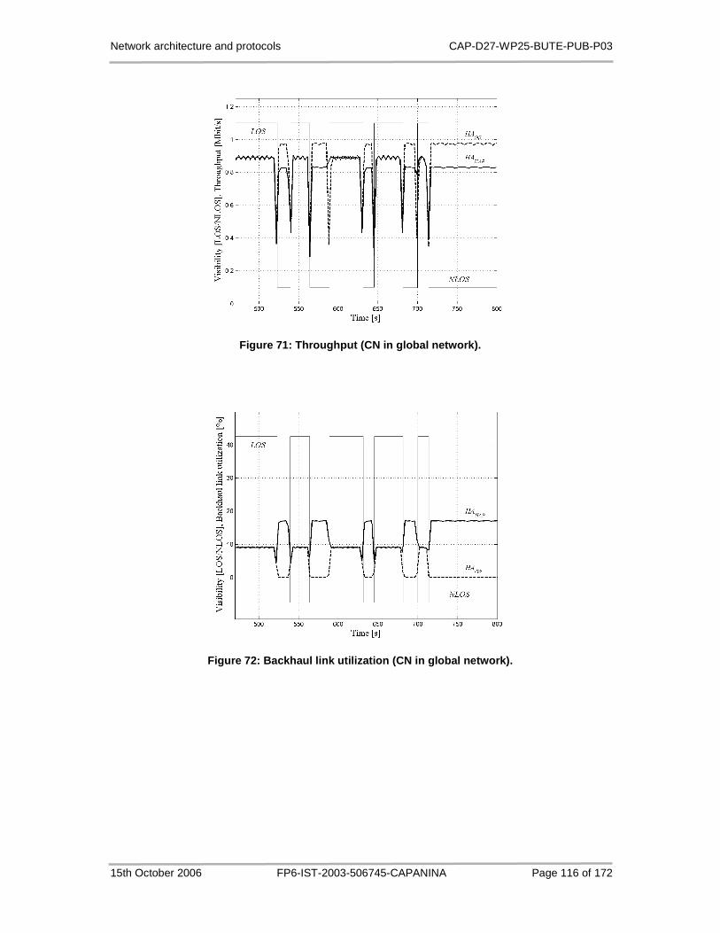
Network architecture and protocols CAP-D27-WP25-BUTE-PUB-P03
15th October 2006 FP6-IST-2003-506745-CAPANINA Page 116 of 172
Figure 71: Throughput (CN in global network).
Figure 72: Backhaul link utilization (CN in global network).
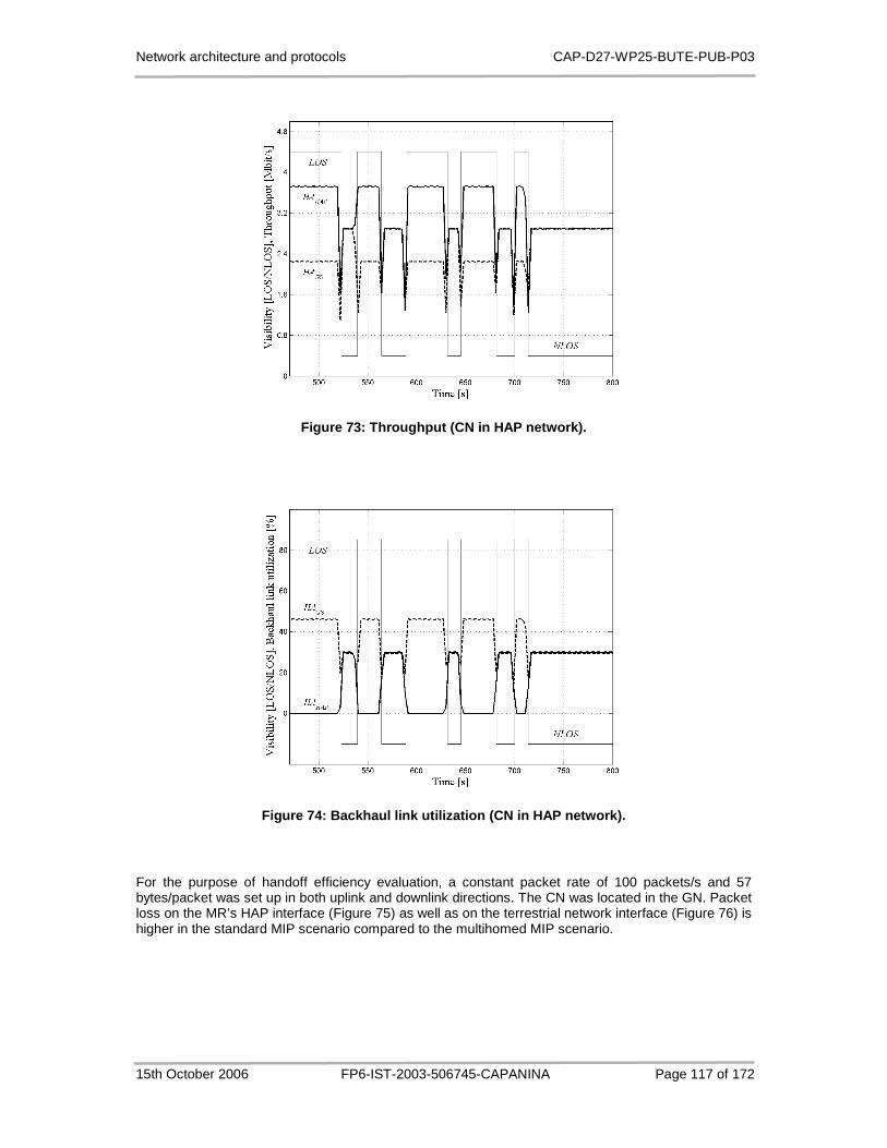
Network architecture and protocols CAP-D27-WP25-BUTE-PUB-P03
15th October 2006 FP6-IST-2003-506745-CAPANINA Page 117 of 172
Figure 73: Throughput (CN in HAP network).
Figure 74: Backhaul link utilization (CN in HAP net work).
For the purpose of handoff efficiency evaluation, a constant packet rate of 100 packets/s and 57 bytes/packet was set up in both uplink and downlink directions. The CN was located in the GN. Packet loss on the MR’s HAP interface (Figure 75) as well as on the terrestrial network interface (Figure 76) is higher in the standard MIP scenario compared to the multihomed MIP scenario.
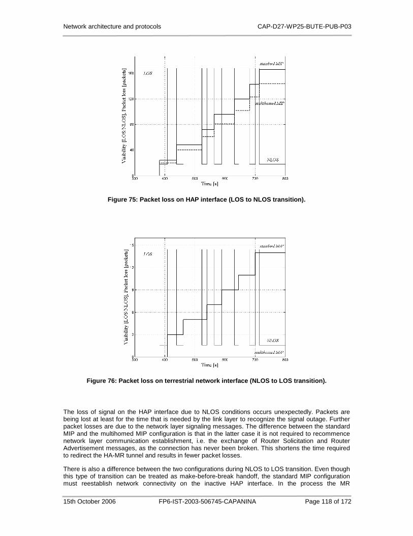
Network architecture and protocols CAP-D27-WP25-BUTE-PUB-P03
15th October 2006 FP6-IST-2003-506745-CAPANINA Page 118 of 172
Figure 75: Packet loss on HAP interface (LOS to NLO S transition).
Figure 76: Packet loss on terrestrial network inter face (NLOS to LOS transition).
The loss of signal on the HAP interface due to NLOS conditions occurs unexpectedly. Packets are being lost at least for the time that is needed by the link layer to recognize the signal outage. Further packet losses are due to the network layer signaling messages. The difference between the standard MIP and the multihomed MIP configuration is that in the latter case it is not required to recommence network layer communication establishment, i.e. the exchange of Router Solicitation and Router Advertisement messages, as the connection has never been broken. This shortens the time required to redirect the HA-MR tunnel and results in fewer packet losses.
There is also a difference between the two configurations during NLOS to LOS transition. Even though this type of transition can be treated as make-before-break handoff, the standard MIP configuration must reestablish network connectivity on the inactive HAP interface. In the process the MR

Network architecture and protocols CAP-D27-WP25-BUTE-PUB-P03
15th October 2006 FP6-IST-2003-506745-CAPANINA Page 119 of 172
deactivates the terrestrial interface and acquires a new CoA on the HAP interface. Doing so, there is a short period of broken connectivity, which results in packet loss (Figure 76). Note that the amount of loss is significantly lower compared to Figure 75 because the reestablishment of the link layer connectivity does not add to the loss period.
The multihomed MIP configuration switches seamlessly to the HAP interface without any packet being lost. The modified multihomed MIP configuration, which includes extensions to support non-topological movements and allows sending outbound data to non-primary HA, was also evaluated. The introduction of non-topological type of handoff does not result in significant improvements, at least not in our simulation scenario. The avoidance of network layer connection reestablishment accelerates route convergence to its optimal topology. However, no extra packets are being saved from loss.
The modification of the HAHA protocol results in improved handoff efficiency. The requirement for primary HA switching in connection with the restriction that only primary agent may forward outbound data, results in packets being discarded by the non-primary home agent. Note that MR must wait for the acknowledgement from the new primary agent, while data continue to be forwarded to the old primary HA. In Figure 77 the number of discarded packets by the non-primary HA is shown in the multihomed MIP scenario. Allowing non-primary HA to forward outbound data eliminates the problem.
Figure 77: Discarded packets on non-primary HA.
5.7.5 Open Issues
One of the open issues in routing protocol implementation supporting high speed moving vehicles is a path selection algorithm in case of multiple bi-directional tunnels. The mode of operation may be primary-secondary or peer-to-peer. In the first case one tunnel has precedence over the other at all times, except when it is unavailable, e.g. NLOS conditions. The other mode can be beneficial in case of comparable costs of using a particular access technology. Efficient fault detection mechanisms are necessary to recover at timely fashion. While link level trigger may be used in a MR, the way MR's HA is informed remains an open issue. Lack of standardized tunnel liveness protocol requires further research. Continuous transmission of heartbeat messages, explicit notifications, frequent binding updates and other mechanisms need to be reconsidered.
Multi-router site, e.g. a train with one MR per car, needs some form of routers’ coordination. The coordination should cover advertising of the same prefix and relaying between MRs everything that

Network architecture and protocols CAP-D27-WP25-BUTE-PUB-P03
15th October 2006 FP6-IST-2003-506745-CAPANINA Page 120 of 172
needs to be relayed in case of a router failure. Basically, there are two kinds of problems associated with the prefix delegation in case of multiple HAs or MRs. First, there is a question how multiple HAs would delegate the same prefix to the mobile network. Multiple routers case poses a second question regarding the mechanism for MRs synchronization in order to advertise the same prefix. Prefix delegation is currently under investigation by the NEMO working group.
As a consequence of multiple interfaces, multiple care-of-addresses are assigned for the same prefix. This opens a multiple binding problem.
Due to train modularity, a splitting scenario must be supported. If a mobile network splits because two MRs go apart, the only available prefix will then be registered by two different MRs on different links. The problem emerges for the HA, which has no way to establish which node with an address configured from the prefix is attached to which MR. Forcible removal of the prefix from one or all MRs is possible solution to the problem. Other solutions should be investigated in the future.
5.8 Summary
This chapter analyzed network layer mobility support in specific environment involving communications between high speed vehicles and HAP network. Some original contributions were proposed. The problem of routing to a mobile node was split into micro and macro-mobility parts. Apart from that division, access mobility was considered as the lowest level of mobility. Mobility within a single HAP was proposed to be implemented on link layer, i.e. as access mobility, because loose coupling with network layer mobility enables exploitation of specific HAP access technology. IP-based micro-mobility protocols were proposed for the inter-platform movements. The main concepts involved into mobility support, such as MIP, HMIP and mobile routers were analyzed in the HAP-to-train scenario. The protocols were mapped onto HAP network architecture. Support for efficient path optimization and network layer handoff procedures were identified as the major factors that affect utilization of wireless network resources. They are particularly important in the HAP network architecture, in which the access network is separated from the global network by bottleneck links and where the majority of mobile users access the network through mobile routers.
Proxy MAP functionality in HMIP domain nodes was proposed in order to tackle intra-domain path optimization. This HMIP capability is lost if multi-level MIP is required and NEMO technology is used. PMAP extension of HMIP is transparent to home agents, correspondent nodes, mobile routers, and to mobile nodes. Basically, PMAP node intercepts all packets destined to MAP address and behaves as a regular MAP node. The inter-domain traffic takes the optimal path because tunnels are terminated at the very border of the network. Numerical evaluation of mean route length in an HMIP domain with multiple layers demonstrated the effectiveness of the proposed solution. Intra-domain optimization improves TCP flow performance because data usually experience less delay on optimized routes. TCP performance was evaluated by simulations using the ns-2 simulator.
We showed that careful selection of home agent location may significantly reduce network burden due to HAP wide coverage area and expected localized mobility. Placement optimization of MIP home agent entity in this particular environment was proposed and evaluated. Discontinuous LOS conditions were simulated. The optimization is most rewarding for communications that cannot bypass mobile router's home agent.
Multihoming support can provide route efficiency, fast handover between HAP and terrestrial links, as well as alleviate connectivity problem during NLOS conditions if quasi-deterministic route patterns are in place. Analysis of multihoming configurations in the context of HAP networks and mobile routers was provided. We showed that multiple HAs increase throughput and reduce load on scarce wireless links. Simultaneous usage of multiple access interfaces is beneficial in terms of handoff efficiency.
Main issues that need to be addressed in the future were identified. Among them, efficient failure detection, HA and MR synchronization, prefix delegation, management of multiple bindings and handling of split mobile networks were particularly exposed.

Network architecture and protocols CAP-D27-WP25-BUTE-PUB-P03
15th October 2006 FP6-IST-2003-506745-CAPANINA Page 121 of 172
6 All-Optical Backhaul HAP Network
6.1 Introduction
Due to relatively small coverage area in comparison to satellites, and due to the nature of data traffic, the traffic generated in a HAP network will be predominantly long distance, i.e. connections will mostly extend beyond the single HAP footprint, requiring a terrestrial or airborne transport network and in most cases a transition to other networks via appropriate gateways. This puts particularly demanding requirements to backhaul uplink and downlink between HAP and the fixed ground station hosting a gateway, which will have to carry the aggregate traffic load from/to several tens or hundreds of cells. Thus, at least one ground station is expected to be positioned in each HAP coverage area, but their number will actually have to be based on link budget calculation taking into account also the expected traffic load.
During the second year trials the CAPANINA project confirmed the possibility to use free-space optics for the uplink/downlink (UL/DL) between HAP and a fixed ground station in cloud-free conditions, achieving a remarkable 1.25 GBit/s downlink transmission from the stratosphere to an optical receiver on the ground over a maximum link distance of 64 km [82][15][16]. Such backhaul throughputs are now moving the pressure to provide sufficient throughput to transport networks, making stratospheric optical transport networks (OTN) based on optical interplatform links (IPLs) the enabling technology to manage high traffic volumes in a meshed HAP system and satisfy the increasing traffic demand. The use of free-space optics both for UL/DL and IPL makes possible the establishment of all-optical backhaul network based on HAPs. A general network architecture depicting the concept of all-optical backhaul network is shown in Figure 78, with free-space optics used on backhaul uplink/downlink as well as on inter-platform links, while user uplink/downlink is still based on mm-wave radio frequency links and are not considered any further in this chapter.
optical
backhaul link
optical
backhaul link
optical
backhaul link
Figure 78: General all-optical transport network ar chitecture.
In the following we consider a platform independent system, assuming that suitable station keeping mechanisms are implemented which allow establishment and maintenance of free-space optical links between platforms and backhaul free-space optical links between platform and ground station. These

Network architecture and protocols CAP-D27-WP25-BUTE-PUB-P03
15th October 2006 FP6-IST-2003-506745-CAPANINA Page 122 of 172
free-space optical links can be used to establish a communication system using HAPs with various network topologies.
The rest of this chapter first briefly discusses physical constraints for the implementation of optical IPLs. Next, the concept and implementation of the optical transport network on top of physical IPL and UL/DL topology is addressed. After describing the concept of WDM links, the wavelength routing and OTN dimensioning are conceptually assessed for two reference network topologies with special attention given to the number of required different wavelengths. In particular, a wavelength routed network is based on assigning a separate wavelength channels to dedicated pairs of nodes, and the number of required wavelengths in the network depends on the physical topology, which eventually dictates the potential need for implementation of technologies supporting double/multiple hop routing. This is followed by a brief introduction of routing and wavelength assignment (RWA) algorithms, to support their implementation in the simulation model. Namely, while the number of required wavelengths can be determined analytically for some regular topologies with pre-defined routing, general topologies potentially using adaptive routing require the number of needed wavelengths to be determined by simulations. As an example we provide some representative simulation results investigating the impact of physical network topologies, the effect of link failure and the performance of different RWA schemes.
6.2 IPL Physical Constraints
For two HAPs to establish a direct functional IPL between each other, the first condition is to have line-of-sight (LoS). In terms of maximum distance between two HAPs several important restrictions should be considered. It is important to guarantee that the IPLs stay above the altitude of the clouds, in order to avoid signal propagation through clouds for a given height of the platforms. This implies that for a particular HAP altitude there is a related maximum possible interplatform distance D between two interconnected stations. It is defined by the minimum altitude of the direct path between two HAPs, called graze height [81], depending on the platform’s and cloud ceiling’s altitudes. On the other hand, given the HAP altitude and the minimum antenna elevation angle of the ground receivers, the radius r of the HAP coverage area is determined. In order to achieve contiguous coverage, the distance between two neighbouring HAPs must be smaller than twice this radius distance (2r). For typical HAP altitude and elevation angle values, 2r is smaller than D [81]. Scenarios with contiguous coverage with typical minimum elevation angles between 20 and 30 degrees, resulting in r in the range between 35 and 55 km, do not need to cope with propagation through clouds. However for interconnection of isolated HAPs this limitation (i.e. the altitude of the clouds with respect to the minimum altitude of the IPL) needs to be considered. Therefore, to interconnect very remote coverage islands platform to satellite links (PSL) may be required.
Furthermore, it should be taken into account that also the operational altitudes of HAPs are limited (typically between 17 km and 22 km) by given natural conditions such as wind strength and air density, thus preventing establishment of extremely long interplatform links between platforms at extreme heights.
Table 12 presents the dependence between a HAPs’ altitude, optical IPL’s distance and the graze height. It can be noticed that if HAPs would be floating at 22 km altitude and the graze height would be 13 km, the IPL maximum distance is 985 km.

Network architecture and protocols CAP-D27-WP25-BUTE-PUB-P03
15th October 2006 FP6-IST-2003-506745-CAPANINA Page 123 of 172
Table 12: HAP system scenarios (HAP altitude – IPL length) [81].
Scenario (HAP altitude –IPL length)
HAP altitude (km) Optical IPL distance (km)
Graze height (km)
High-Long 30 932 13
High-Short 30 461 25.7
Medium-Short 24 375 21.25
Low-Long 18 506 13
Low-Short 18 253 16.74
Besides the geometric restrictions on IPL distance, there are several other restrictions for optical IPLs [81]:
- All the HAPs have to be at the same altitude from Earth’s surface to avoid higher background interference for the HAP with higher altitude.
- Attenuation in the stratosphere is caused by mainly three effects: molecular absorption, scattering by droplets or ice crystals and in clouds.
- Air turbulence affects long lightpaths and the receiver sees a random distribution of photons. In addition to atmosphere, the motion of the platform also impacts upon the temporal spectrum of power fluctuations.
- Due to propagation conditions, only few laser wavelengths are suitable for IPLs, the most highly credited is the one at 1550 nm.
Furthermore, IPLs must be permanent, they are established after the HAP reaches its targeted position until it is disconnected from the network for replacement, repositioning, maintenance, etc. Since HAP does not keep always the same position (slightly moves around the nominal position) and is subject to space vibrations, highly directional steerable transmitter/receiver antennas are required. To solve permanent IPL establishment, pointing, acquisition and tracking (PAT) technologies will be implemented [89].
6.3 Optical Transport Network
The concept of OTN is based on assigning separate channels (separate wavelengths, time slots on separate wavelengths) to dedicated pairs of nodes (HAPs and ground stations). These channels can be established (semi-)permanently or on demand, depending on the optical routing/switching technology used, such as WDM routing or optical burst switching. In the following we focus on the mature OTN concept using WDM routing, discussed more in detail in this section along with limitations in terms of number of different wavelengths required by different payload configurations and network topologies.
6.3.1 WDM Routing
We assume the OTN based on assigning separate wavelength channels to dedicated pairs of nodes (HAPs, GSs) and one (or more) continuous path(s) between them, so-called lightpaths. This requires employing wavelength-division multiplex (WDM) links and on-board wavelength routing. Different lightpaths sharing the same physical optical link must be assigned different wavelengths, which requires wavelength reuse optimization. In reality, the number of different wavelengths per optical link is limited by the available bandwidth and required channel separation. Current technology allows the usage of 64 different wavelengths [14]. In order to achieve efficient WDM routing it is possible to use any number of these available wavelengths without any further restrictions. Namely, the multiplexed signal will face the same wavefront distortion and fading effects, regardless of the number of wavelengths used. Moreover, since the power consumed by currently available wavelength transmission technologies (in particular by Erbium Doped Fiber Amplifiers (EDFAs)) only depends on

Network architecture and protocols CAP-D27-WP25-BUTE-PUB-P03
15th October 2006 FP6-IST-2003-506745-CAPANINA Page 124 of 172
the number of bits/s (the energy per bit is constant), it is not expected that power consumption or any other network resource usage will rise only as a consequence of higher number of wavelengths employment.
The limitation of different wavelengths per optical link makes single-hop optical connectivity – where each origin-destination (OD) pair of nodes is served by a dedicated lightpath – possible only for networks with low to moderate number of nodes. A single hop optical transmission is delivering data between the source and destination nodes without Optic-Electronic-Optic (OEO) conversion in any of the intermediate nodes. The number of required bi-directional lightpaths within the network of N nodes equals L = N × (N - 1)/2, with the number of wavelengths in the network and per IPL depending on the physical topology of the optical transport network.
A dual-(multi)hop solution, requiring one (or more) OEO conversion(s) in intermediate nodes, can already be used for wavelength routing in larger networks with several tens of nodes, connecting an arbitrary OD pair by a unique sequence of two lightpaths. Further generalization leads to multi-hop solutions with more than two different lightpaths used between the origin and destination node. In the extreme case of maximum-hop solution the optical connectivity is actually the same as the physical connectivity, so we can no longer speak about wavelength routing.
The use of a dedicated wavelength to route data from a source to a destination is referred to as wavelength routing and a network that employs this technique is known as a wavelength routed network. Such a network consists of wavelength routing switches (or routing nodes) which are interconnected by fibre optics or free space optics. Some routing nodes, referred to as cross-connects, are attached to access stations where data from several end users can be multiplexed into a single WDM channel. An access station also provides optical to electronic (OE) conversion and vice versa, to interface the optical network with electronic equipment. A wavelength routed network that carries data from one access station to another without intermediate Optic-Electronic-Optic (OEO) conversion is referred to as an all-optical wavelength routed network [88].
When data arrive at a node in a WDM network, the optical wave can be converted to electric wave and processed by electronic circuits. Before the data is sent on an optical network, the inverse, electrical to optical transformation has to be done. In an optically linked network nodes perform OEO conversion in order to route traffic as they are not enabled with optical routing equipment.
A network with wavelength conversion capabilities allows a route to be formed by more sections, each potentially employing a different wavelength. Nodes that separate sections with different wavelengths convert the wavelength on incoming link to the one of the outgoing link and vice versa.
OEO conversion involves complex and power consuming equipment and introduces delays due to complicated processing. This is not feasible for real time traffic and it should only be used as a last alternative if the other techniques are not available or feasible. Wavelength conversion, on the other hand, is much faster than OEO as it does not assume transmission media conversion but involves both power and economically costly equipment. In terrestrial fibre-optic based WDM networks this solution is used with various improvements, using different variants of sparse conversions, however in a HAP-based network this implies using different payload on each platform, thus reducing the network flexibility.
In terms of hardware, the single-hop approach would be based on an on-board optical cross connect (OCX), cf. Figure 79, whereas in the dual-hop/multi-hop solution an on-board add-drop multiplexer (ADM), cf. Figure 80, has to be used requiring at maximum one conversion to the electric domain and back to optical domain [14].
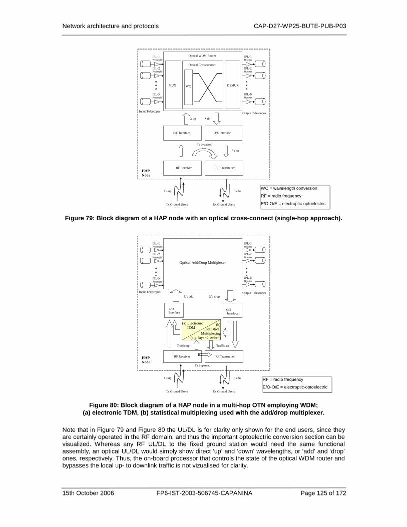
Network architecture and protocols CAP-D27-WP25-BUTE-PUB-P03
15th October 2006 FP6-IST-2003-506745-CAPANINA Page 125 of 172
Optical Crossconnect
MUX WC
Optical WDM Router
λ up λ dn
Input Telescopes
O/E Interface
DEMUX
RF Receiver RF Transmitter
f´s bypassed
f´s dn
f´s up f´s dn
Rx Ground Users Tx Ground Users
IPL-1 Preamplif.
IPL-2 Preamplif.
IPL-N Preamplif.
IPL-1 Booster
IPL-2 Booster
IPL-N Booster
Output Telescopes
E/O Interface
HAP Node
Figure 79: Block diagram of a HAP node with an opti cal cross-connect (single-hop approach).
Optical Add/Drop Multiplexer
λ´s add λ´s drop
Input Telescopes
O/E Interface
RF Receiver RF Transmitter
f´s bypassed
Traffic dn
f´s up f´s dn
Rx Ground Users Tx Ground Users
IPL-1 Preamplif.
IPL-2 Preamplif.
IPL-N Preamplif.
IPL-1 Booster
IPL-2 Booster
IPL-N Booster
Output Telescopes
E/O Interface
HAP Node
(a) Electronic TDM
Traffic up
(b) Statistical Multiplexing (e.g. layer 2 switch)
Figure 80: Block diagram of a HAP node in a multi-h op OTN employing WDM; (a) electronic TDM, (b) statistical multiplexing us ed with the add/drop multiplexer.
Note that in Figure 79 and Figure 80 the UL/DL is for clarity only shown for the end users, since they are certainly operated in the RF domain, and thus the important optoelectric conversion section can be visualized. Whereas any RF UL/DL to the fixed ground station would need the same functional assembly, an optical UL/DL would simply show direct ‘up’ and ‘down’ wavelengths, or ‘add’ and ‘drop’ ones, respectively. Thus, the on-board processor that controls the state of the optical WDM router and bypasses the local up- to downlink traffic is not vizualised for clarity.
WC = wavelength conversion
RF = radio frequency
E/O-O/E = electroptic-optoelectric
RF = radio frequency
E/O-O/E = electroptic-optoelectric

Network architecture and protocols CAP-D27-WP25-BUTE-PUB-P03
15th October 2006 FP6-IST-2003-506745-CAPANINA Page 126 of 172
6.3.2 Physical Topologies
As mentioned above, an optical transport network based on HAPs using WDM routing requires a wise network dimensioning and resource allocation due to the limited number of wavelengths available per link between two platforms. While deployed HAP based networks keep more or less the same position (i.e. platforms fly/float around the nominal position) and the network can be built gradually according to the increasing needs. The network’s physical topology will thus be irregular and HAPs may eventually have different number of IPL transceivers on board (the maximum number will be most likely restricted by a payload mass/consumption/volume constraint). If the network is too large to establish a WDM routed lightpath between each pair of HAPs, a dual/multi-hop solution will have to be considered.
The assignment of single-hop/multi-hop connections between nodes has to take into account some general characteristics of all-optical HAP networks as well as the particular network topology under consideration. In particular, optical backhaul UL/DL is extremely dependent on the weather, requiring clear sky propagation conditions. In case of non-LOS, traffic will have to be rerouted to another HAP with better conditions on the UL/DL. This makes the choice for single-hop and double-hop lightpaths quite straightforward. The potential need to re-route the whole traffic to an arbitrary HAP with good UL/DL propagation conditions, to make use of platform diversity, favours single-hop lightpaths between all (most) HAPs and to remote ground stations in the coverage area of HAPs having no or very low statistical correlation in link outages due to bad propagation conditions, thus providing a two hop path restoration from one end-HAP with bad to another with clear sky propagation conditions [14].
The dimensioning of OTN directly affects the wavelength routing and has a significant influence on the overall network performance. Once the physical topology of the network is defined the major design criteria for the overlay OTN are the number of required wavelengths per optical link, link utilization, link capacity and the average link outage time [14].
In addition to irregular physical topologies of HAP based networks some HAPs might also have no GS connectivity while others might connect to more than one GS, making the task of network dimensioning even more complex. In the following we analytically analyse two physical topologies, full mesh topology and bus topology, considering bidirectional communication on a single wavelength. These topologies are representing the lower and the upper boundary in terms of wavelength requirements for the worst case link in homogeneous all-optical network (i.e. homogeneous number of GSs per HAP). However, to analyse a large and general network topology, possibly requiring double/multiple hops, it is necessary to develop a network dimensioning tool, since the analytical derivation of required wavelengths will not be a trivial task, if possible at all [14].
6.3.2.1 Full Mesh Topology
An example of full mesh topology consisting of five HAPs and a single GS per HAP is depicted in Figure 81. Each HAP has physical optical connection to all other HAPs and to the ground station within its coverage area.
HAPA
HAPD
HAPE
HAPC
HAPB
GSA
GSE
GSD
GSC
GSB
Figure 81: Full mesh physical topology.
In the analysis we first assume N HAPs in full mesh topology with one ground station per HAP (i.e. N HAPs in the network). For each HAP to communicate to all the other HAPs, there is no need for WDM as the platforms are physically interconnected. So a single wavelength per physical link suffices to

Network architecture and protocols CAP-D27-WP25-BUTE-PUB-P03
15th October 2006 FP6-IST-2003-506745-CAPANINA Page 127 of 172
allow communication between each pair of HAPs in a fully meshed topology, no matter how big the network is:
1=IPLλ . (6.1)
On the UL/DL, N wavelengths are needed for a ground station to establish a connection over WDM to each HAP and (N – 1) wavelengths to establish a connection to each of the ground stations belonging to other HAPs. Thus, the number of wavelengths required on each backhaul UL/DL, λUL/DL, is given as:
)(/ 1NNDLUL −+=λ . (6.2)
For a fully interconnected network with a single GS per HAP (HAP-HAP, HAP-GS and GS-GS), four wavelengths per IPL are needed independent of the size of the network:
4IPL ='λ . (6.3)
Finally, for a homogeneous allocation of resources (the same number of wavelengths on all optical links) on both IPLs and ULs/DLs, the minimum number of wavelengths in the system required to achieve full interconnectivity for a full mesh topology can be expressed as:
{ } 1)1(,4max >−+= N ; NNλ . (6.4)
The above analysis is now generalised for a full mesh topology with multiple ground stations per HAP, i.e. considering a network with N HAPs and k GSs connected to each HAP. With these assumptions Equation (6.1) remains the same, i.e. in order to establish optical links between al HAPs there is no need for WDM links as all platforms are physically interconnected.
The total number of wavelengths required on a UL/DL is the sum of the wavelengths connecting the ground station to all the N HAPs, the wavelengths connecting the GSs to all the other HAPs’ GSs (N - 1)k, and the wavelengths connecting the GS to the other k - 1 GSs in the same HAP coverage area. Thus, Equation (6.2) can be generalised as follows:
11kNDLUL −+= )(/λ . (6.5)
The total number of wavelengths required on an IPL is the sum of the wavelength required to connect the two extreme nodes of the IPL, the 2k wavelengths required to connect the HAP on one extreme to the other HAPs ground stations, and the k2 wavelengths required to connect each HAP’s ground station to each other HAP’s ground station, generalising Equation (6.3) in:
2IPL 1k )(' +=λ . (6.6)
The maximum of Equations (6.5) and (6.6) gives the minimum number of required wavelengths in a full mesh topology, generalising Equation (6.4):
{ } 1,max /' >= N ; DLULIPL λλλ . (6.7)
Example values for wavelength requirements in the full mesh topology consisting of 2 to 10 HAPs with 1 to 3 GSs per HAP (i.e. N = [2,10] and k = [1,3]), calculated with the above equations, are given in Table 13.
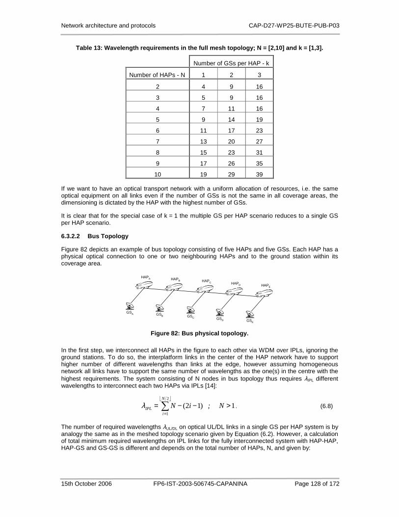
Network architecture and protocols CAP-D27-WP25-BUTE-PUB-P03
15th October 2006 FP6-IST-2003-506745-CAPANINA Page 128 of 172
Table 13: Wavelength requirements in the full mesh topology; N = [2,10] and k = [1,3].
Number of GSs per HAP - k
Number of HAPs - N 1 2 3
2 4 9 16
3 5 9 16
4 7 11 16
5 9 14 19
6 11 17 23
7 13 20 27
8 15 23 31
9 17 26 35
10 19 29 39
If we want to have an optical transport network with a uniform allocation of resources, i.e. the same optical equipment on all links even if the number of GSs is not the same in all coverage areas, the dimensioning is dictated by the HAP with the highest number of GSs.
It is clear that for the special case of k = 1 the multiple GS per HAP scenario reduces to a single GS per HAP scenario.
6.3.2.2 Bus Topology
Figure 82 depicts an example of bus topology consisting of five HAPs and five GSs. Each HAP has a physical optical connection to one or two neighbouring HAPs and to the ground station within its coverage area.
HAPA
GSA
HAPB
GSB
HAPC
GSC
HAPD
GSD
HAPE
GSE
Figure 82: Bus physical topology.
In the first step, we interconnect all HAPs in the figure to each other via WDM over IPLs, ignoring the ground stations. To do so, the interplatform links in the center of the HAP network have to support higher number of different wavelengths than links at the edge, however assuming homogeneous network all links have to support the same number of wavelengths as the one(s) in the centre with the highest requirements. The system consisting of N nodes in bus topology thus requires λIPL different wavelengths to interconnect each two HAPs via IPLs [14]:
∑=
>−−=2
1
1)12(N
iIPL N ; iNλ . (6.8)
The number of required wavelengths λUL/DL on optical UL/DL links in a single GS per HAP system is by analogy the same as in the meshed topology scenario given by Equation (6.2). However, a calculation of total minimum required wavelengths on IPL links for the fully interconnected system with HAP-HAP, HAP-GS and GS-GS is different and depends on the total number of HAPs, N, and given by:

Network architecture and protocols CAP-D27-WP25-BUTE-PUB-P03
15th October 2006 FP6-IST-2003-506745-CAPANINA Page 129 of 172
[ ]
1N ; 2N 2N 4
1i2N42N
1iIPL
>=
−−= ∑=
)('λ. (6.9)
For a uniform capacity allocation on both IPLs and UL/DL, the minimum wavelengths needed to achieve full interconnectivity for a bus topology is thus given as a maximum of Equations (6.2) and (6.9) [14]:
{ } 1N ; 1NN 2N 2N 4 >−+= )(,maxλ . (6.10)
Note that for the particular case of N = 2 the system falls also into full mesh physical topologies.
Now we will derive generalised formulas for bus topology with multiple ground stations per HAP, considering a network with N HAPs and k ground stations connected to each HAP. By analogy from the full mesh topology these assumptions again do not affect the required number of wavelengths λIPL to interconnect all HAPs, thus Equation (6.8) remains unchanged [14]. Furthermore, the total number of wavelengths required on a UL/DL is calculated the same way as for the full mesh topology and is given by Equation (6.5). The only difference in a multiple GS per HAP scenario is thus in the total number of wavelengths required on an IPL, given by the sum of wavelengths required on each IPL (as we move from the extremities of the bus towards the centre this number increases) to connect pairs of HAPs. This number is then increased by the number of wavelengths that connect HAPs to GSs and GSs to GSs:
[ ]
1N ; 2N 2N1k
k2
N
2
Nk
2
N
2
N21i2N
2
2N
1i
2IPL
>+=
+
+−−= ∑=
)(
)('λ. (6.11)
The total minimum number of required wavelengths in bus network topology of N HAPs and k GSs per HAP is thus given as the maximum of λUL/DL (cf. Equation (6.5)) and λIPL' (cf. Equation (6.11)):
{ } 1,max /' >= N ; DLULIPL λλλ (6.12)
Again we can see that by setting k to 1 the multiple GS per HAP scenario reduces to a single GS per HAP scenario, thus validating the above equations.
Example values for wavelength requirements in the bus topology consisting of 2 to 10 HAPs with 1 to 3 GSs per HAP (i.e. N = [2,10] and k = [1,3]), calculated with equations given above, are summarised in Table 14.
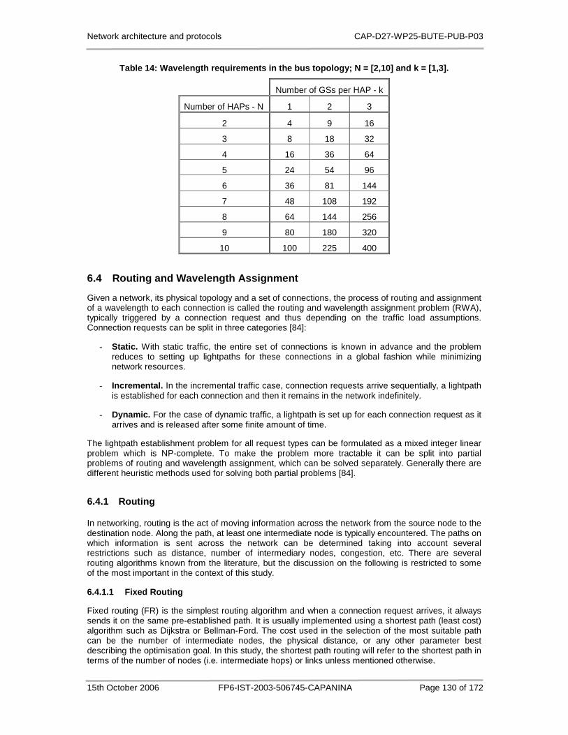
Network architecture and protocols CAP-D27-WP25-BUTE-PUB-P03
15th October 2006 FP6-IST-2003-506745-CAPANINA Page 130 of 172
Table 14: Wavelength requirements in the bus topolo gy; N = [2,10] and k = [1,3].
Number of GSs per HAP - k
Number of HAPs - N 1 2 3
2 4 9 16
3 8 18 32
4 16 36 64
5 24 54 96
6 36 81 144
7 48 108 192
8 64 144 256
9 80 180 320
10 100 225 400
6.4 Routing and Wavelength Assignment
Given a network, its physical topology and a set of connections, the process of routing and assignment of a wavelength to each connection is called the routing and wavelength assignment problem (RWA), typically triggered by a connection request and thus depending on the traffic load assumptions. Connection requests can be split in three categories [84]:
- Static. With static traffic, the entire set of connections is known in advance and the problem reduces to setting up lightpaths for these connections in a global fashion while minimizing network resources.
- Incremental. In the incremental traffic case, connection requests arrive sequentially, a lightpath is established for each connection and then it remains in the network indefinitely.
- Dynamic. For the case of dynamic traffic, a lightpath is set up for each connection request as it arrives and is released after some finite amount of time.
The lightpath establishment problem for all request types can be formulated as a mixed integer linear problem which is NP-complete. To make the problem more tractable it can be split into partial problems of routing and wavelength assignment, which can be solved separately. Generally there are different heuristic methods used for solving both partial problems [84].
6.4.1 Routing
In networking, routing is the act of moving information across the network from the source node to the destination node. Along the path, at least one intermediate node is typically encountered. The paths on which information is sent across the network can be determined taking into account several restrictions such as distance, number of intermediary nodes, congestion, etc. There are several routing algorithms known from the literature, but the discussion on the following is restricted to some of the most important in the context of this study.
6.4.1.1 Fixed Routing
Fixed routing (FR) is the simplest routing algorithm and when a connection request arrives, it always sends it on the same pre-established path. It is usually implemented using a shortest path (least cost) algorithm such as Dijkstra or Bellman-Ford. The cost used in the selection of the most suitable path can be the number of intermediate nodes, the physical distance, or any other parameter best describing the optimisation goal. In this study, the shortest path routing will refer to the shortest path in terms of the number of nodes (i.e. intermediate hops) or links unless mentioned otherwise.

Network architecture and protocols CAP-D27-WP25-BUTE-PUB-P03
15th October 2006 FP6-IST-2003-506745-CAPANINA Page 131 of 172
This routing approach is simple but has some disadvantages. If resources on a path run out, it leads to high blocking for dynamic traffic, or results in a large number of resources being used in the static case. It is not a fault tolerant algorithm, so if a link breaks it blocks all the requests that previously used that link on their path [84].
6.4.1.2 Fixed Alternate Routing
Fixed alternate routing (FAR) eliminates some of the disadvantages of FR by remembering multiple routes. Each node in the network stores a table with more possible (link disjoint) routes to each destination. These routes can be the shortest path, the second (and subsequent) shortest path(s). When a connection request arrives, the node tries to establish a route to the destination on the first entry of the table corresponding to that destination node. If the connection cannot be set up it attempts to connect on each of the alternative routes stored in turn until it succeeds or runs out of entries.
FAR provides simplicity of control for setting up and tearing down lightpaths and it may also be used to provide some degree of tolerance upon link failures. Another advantage is that it can significantly reduce the network’s blocking probability compared to FR [84]. If too many alternative routes are remembered in the routing tables, this routing algorithm may have storage problems.
6.4.1.3 Adaptive Routing
Adaptive routing (AR) is ”smarter” than the previous two routing types in the way that, when attempting to route a connection, it takes into account the current state of the network. Different factors contribute to the state of the network such as the set of established connections, the faulted links, the congested links, etc. Thus, AR can route a connection according to several criteria and here we describe two representatives.
Adaptive shortest cost path routing is well suited for the use in wavelength converted networks. Under this approach, each link in the network is set a cost. If the cost is suitably chosen, the algorithm chooses a wavelength converted path for a request only if wavelength continuous path for the given source-destination nodes does not exist [84].
Least congested path routing is another form of adaptive routing that works similarly to alternate routing. For each source-destination pair, a sequence of routes is pre-selected. Upon the arrival of a request, the least congested path among the pre-determined routes is chosen. The value of the congestion on a path is given by the link with the least resources of the path [84].
In AR, a connection request is blocked only if there are no resources (wavelength converted path, decongested path, etc.) available in the network. Another advantage of AR is that it results in lower connection blocking than both FR and FAR. Unfortunately AR requires extensive support from the control and management protocols to continuously update the routing tables at the nodes.
6.4.1.4 Fault Tolerant Routing
When setting up connections in a wavelength-routed optical WDM network, it is often desirable to provide some degree of protection against link and node failures in the network by reserving some amount of spare capacity, as already discussed in Section 4.3 for MPLS-based solutions for error detection and recovery. A common approach to protection is to set up two link-disjoint lightpaths for every connection request. One lightpath, called the primary lightpath, is used for transmitting data, while the other lightpath is reserved as a backup in the event that a link in the primary lightpath fails. This approach can be used to protect against any single-link failures in the network. To further protect against node failures, the primary and alternate paths may also be node-disjoint [84].
Fixed-alternate routing provides a straightforward approach to handling protection. By choosing the alternate paths such that their routes are link-disjoint from the primary route, we can protect the connection from any single-link failures by allocating one of the alternate paths as a backup path.
In adaptive routing, a protection scheme may be implemented in which the backup path is set up immediately after the primary path has been established. The same routing protocol may be used to determine the backup path.

Network architecture and protocols CAP-D27-WP25-BUTE-PUB-P03
15th October 2006 FP6-IST-2003-506745-CAPANINA Page 132 of 172
6.4.2 Wavelength Assignment
A wavelength routed network is similar to a circuit switched network as for each connection a wavelength is allocated during its lifetime. Given a connection request and a path (or a set of paths) wavelength assignment algorithms search for free wavelengths to establish the connection. Several heuristic approaches have been proposed in the literature to solve this problem, some of the main representatives being [84]:
- Random Wavelength Assignment
- First Fit Wavelength Assignment
- Least Used/SPREAD Wavelength Assignment
- Most Used/PACK Wavelength Assignment
- Min Product Wavelength Assignment
- Least Loaded Wavelength Assignment
- MAX-SUM Wavelength Assignment
- Relative Capacity Loss Wavelength Assignment
- Wavelength Reservation Assignment
- Protecting Threshold Wavelength Assignment
These heuristics can all be implemented as on-line algorithms and can be combined with different routing schemes. The first eight algorithms attempt to reduce the overall blocking probability for new connections, while the last two approaches aim to reduce the blocking probability for connections that traverse more than one link. There is no outstanding difference between their performances; some obtain good results in single-fibre networks, others in multi-fibre, etc. Random and First Fit give good results with low complexity and computational overhead and do not require global knowledge of the network status, which makes them preferred solutions in practice [84].
6.4.2.1 Random Assignment
Random (R) assignment works by checking for a set of idle wavelengths on a given path. A random wavelength is chosen from that set. If there is no wavelength continuity constraint, then a random wavelength is chosen among the idle ones on each link of the path.
6.4.2.2 First Fit Assignment
The First Fit (FF) assignment algorithm numbers all the wavelengths and assigns those with the lower number before those with higher number, requiring no global information. Compared to Random wavelength assignment, the computation cost of this scheme is lower because there is no need to search the entire wavelength space for each route. The idea behind this scheme is to pack all of the wavelengths in use toward the lower end of the wavelength space, thus inherently saving the higher end of the wavelength space for continuous longer paths.
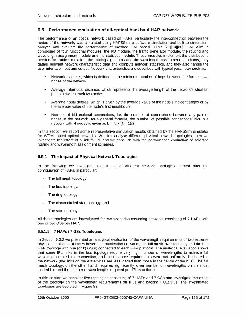
Network architecture and protocols CAP-D27-WP25-BUTE-PUB-P03
15th October 2006 FP6-IST-2003-506745-CAPANINA Page 133 of 172
6.5 Performance evaluation of all-optical backhaul HAP network
The performance of an optical network based on HAPs, particularly the interconnection between the nodes of the network, was simulated using HAPSSim, a software simulation tool built to dimension, analyse and evaluate the performance of meshed HAP-based OTNs [79][13][80]. HAPSSim is composed of four functional modules: the I/O module, the traffic generator module, the routing and wavelength assignment module and the statistics module. These modules implement the distributions needed for traffic simulation, the routing algorithms and the wavelength assignment algorithms, they gather relevant network characteristic data and compute network statistics, and they also handle the user interface input and output. Network characteristics are described with typical parameter such as:
• Network diameter, which is defined as the minimum number of hops between the farthest two nodes of the network.
• Average internodal distance, which represents the average length of the network’s shortest paths between each two nodes.
• Average nodal degree, which is given by the average value of the node’s incident edges or by the average value of the node’s first neighbours.
• Number of bidirectional connections, i.e. the number of connections between any pair of nodes in the network. As a general formula, the number of possible connections/links in a network with N nodes is given as L = N × (N - 1)/2.
In this section we report some representative simulation results obtained by the HAPSSim simulator for WDM routed optical networks. We first analyse different physical network topologies, then we investigate the effect of a link failure and we conclude with the performance evaluation of selected routing and wavelength assignment schemes.
6.5.1 The Impact of Physical Network Topologies
In the following we investigate the impact of different network topologies, named after the configuration of HAPs, in particular:
- The full mesh topology,
- The bus topology,
- The ring topology,
- The circumcircled star topology, and
- The star topology.
All these topologies are investigated for two scenarios assuming networks consisting of 7 HAPs with one or two GSs per HAP.
6.5.1.1 7 HAPs / 7 GSs Topologies
In Section 6.3.2 we presented an analytical evaluation of the wavelength requirements of two extreme physical topologies of HAPs based communication networks, the full mesh HAP topology and the bus HAP topology with one (or k) GS(s) connected to each HAP platform. The analytical evaluation shows that some IPL links in the bus topology require very high number of wavelengths to achieve full wavelength routed interconnection, and the resource requirements were not uniformly distributed in the network (the links on the extremities are less loaded than those in the centre of the bus). The full mesh topology, on the other hand, requires significantly lower number of wavelengths on the most loaded link and the number of wavelengths required per IPL is uniform.
In this section we consider five topologies consisting of 7 HAPs and 7 GSs and investigate the effect of the topology on the wavelength requirements on IPLs and backhaul ULs/DLs. The investigated topologies are depicted in Figure 83.

Network architecture and protocols CAP-D27-WP25-BUTE-PUB-P03
15th October 2006 FP6-IST-2003-506745-CAPANINA Page 134 of 172
(a) Full mesh topology.
(b) Bus topology.
(c) Ring topology. (d) Circumcircled star topology. (e) Star topology.
Figure 83: 7 HAPs / 7 GSs topologies.
We expect that the wavelength requirements on the ring, circumcircled star and star topologies will be somewhere between the wavelength requirements on the full mesh and bus topologies, thus confirming the latter two being the extreme cases. According to Equations (6.7) and (6.12) the minimum number of required wavelengths on a link is 13 for the full mesh topology and 48 for the bus topology.
The five topologies were simulated with the following parameters: simulation time was set to 100 time units, it is considered that, on average, connection requests arrive two in a time unit and last for 4 time units. Simulations were performed for all routing (FR, FAR, AR) and wavelength assignment (R, FF) schemes and the maximum value among the outputs was chosen for the results presented below. We assumed a link supports a high number of different wavelengths (in particular 64 wavelengths, which is larger than the maximum expected 48 in the case of bus topology) so there is no wavelength constraint in the network. With these settings, there is no blocking in the network.
Table 15 presents the simulation results for the five topologies. Experimental results confirm that the largest number of required wavelengths per link will occur for the bus topology. The bus topology needs 48 different wavelengths on the two IPLs in the centre. In the full mesh topology the highest number of wavelengths is required on ULs/DLs, in particular the minimum of 13 different wavelengths are required on each UL/DL to make sure there are no rejected connection requests.

Network architecture and protocols CAP-D27-WP25-BUTE-PUB-P03
15th October 2006 FP6-IST-2003-506745-CAPANINA Page 135 of 172
Table 15: Network topology characteristics and wave length requirements for 7 HAPs / 7 GSs.
Top
olog
y
Net
wor
k
diam
eter
Ave
rage
in
tern
odal
di
stan
ce
Ave
rage
no
dal d
egre
e
Num
ber
of
bidi
rect
iona
l co
nnec
tions
Tra
ffic
Min
. num
ber
of r
equi
red
wav
elen
gths
Crit
ical
lin
k(s)
Full mesh 3 1.923 4 91 inc, dyn 13 all UL/DL
Bus 8 3.462 1.875 91 inc, dyn 48 central IPLs
Ring 5 2.846 2 91 inc, dyn 26 all IPLs
Circ. star 4 2.319 2.714 91 inc, dyn 13 all UL/DL
Star 4 2.582 1.875 91 inc, dyn 24 all IPLs
Ring topology requires the minimum of 26 different wavelengths on all IPLs. According to the network topology characteristics this topology seems to be closer to the bus than to the full mesh as it puts the highest burden on IPLs and also has low average nodal degree (i.e. 2), similar to the bus topology.
Circumcircled star topology needs only 13 different wavelengths on all backhaul UL/DL links, the same as the full mesh topology. If we look at the network diameter of this topology, it is bigger than the one for the full mesh, but smaller than the one for ring and bus topologies. The same holds for the average internodal distance. We can notice from this analysis that there is a correlation between the network diameter, average internodal distance and average nodal degree on one side, and the minimum number of required different wavelengths per link and the type of most burdened link(s) on the other. The higher the average nodal degree and the smaller the average internodal distance, the less wavelengths per link are needed. Higher requirements are put on IPLs for low nodal degree topologies, while for high nodal degree topologies high requirements will occur on backhaul ULs/DLs.
The above observations are confirmed also by the star topology, having similar average internodal distance as the ring topology and the same average nodal degree as the bus topology, resulting in similar number of required wavelengths per link as in the ring topology and critical requirements being posed by IPLs as in the ring and bus topologies. In particular, each IPL in the star topology requires at least 24 different wavelengths.
The above simulation results confirm the analytical results and observations from Sections 6.3.2, as well as indicate interesting correlations between network topology characteristics and resource requirements.
6.5.1.2 7 HAPs / 14 GSs Topologies
In this section we investigate the same network topologies as above, but with increased number of ground stations (see Figure 84), thus being able to confirm the generalised equations from Section 6.3.2 and to discuss the implications of deploying more than one GS per HAP. For the particular case of N = 7 and k = 2, that is a network with 7 HAPs and 2 GSs per HAP (i.e. 14 GSs in total), the minimum number of wavelengths required by the full mesh and the bus topologies is expected to be 20 and 108 according to Equations (6.7) and (6.12).
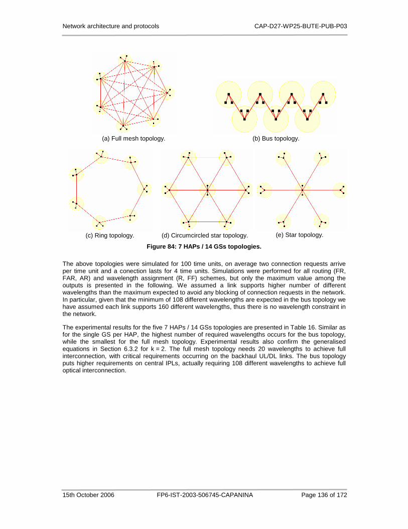
Network architecture and protocols CAP-D27-WP25-BUTE-PUB-P03
15th October 2006 FP6-IST-2003-506745-CAPANINA Page 136 of 172
(a) Full mesh topology.
(b) Bus topology.
(c) Ring topology. (d) Circumcircled star topology. (e) Star topology.
Figure 84: 7 HAPs / 14 GSs topologies.
The above topologies were simulated for 100 time units, on average two connection requests arrive per time unit and a conection lasts for 4 time units. Simulations were performed for all routing (FR, FAR, AR) and wavelength assignment (R, FF) schemes, but only the maximum value among the outputs is presented in the following. We assumed a link supports higher number of different wavelengths than the maximum expected to avoid any blocking of connection requests in the network. In particular, given that the minimum of 108 different wavelengths are expected in the bus topology we have assumed each link supports 160 different wavelengths, thus there is no wavelength constraint in the network.
The experimental results for the five 7 HAPs / 14 GSs topologies are presented in Table 16. Similar as for the single GS per HAP, the highest number of required wavelengths occurs for the bus topology, while the smallest for the full mesh topology. Experimental results also confirm the generalised equations in Section 6.3.2 for k = 2. The full mesh topology needs 20 wavelengths to achieve full interconnection, with critical requirements occurring on the backhaul UL/DL links. The bus topology puts higher requirements on central IPLs, actually requiring 108 different wavelengths to achieve full optical interconnection.
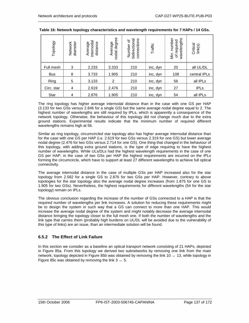
Network architecture and protocols CAP-D27-WP25-BUTE-PUB-P03
15th October 2006 FP6-IST-2003-506745-CAPANINA Page 137 of 172
Table 16: Network topology characteristics and wave length requirements for 7 HAPs / 14 GSs.
Top
olog
y
Net
wor
k
diam
eter
Ave
rage
in
tern
odal
di
stan
ce
Ave
rage
no
dal d
egre
e
Num
ber
of
bidi
rect
iona
l co
nnec
tions
Tra
ffic
Min
. num
ber
of r
equi
red
wav
elen
gths
Crit
ical
lin
k(s)
Full mesh 3 2.233 3.333 210 inc, dyn 20 all UL/DL
Bus 8 3.733 1.905 210 inc, dyn 108 central IPLs
Ring 5 3.133 2 210 inc, dyn 56 all IPLs
Circ. star 4 2.619 2.476 210 inc, dyn 27 IPLs
Star 4 2.876 1.905 210 inc, dyn 54 all IPLs
The ring topology has higher average internodal distance than in the case with one GS per HAP (3.133 for two GSs versus 2.846 for a single GS) but the same average nodal degree equal to 2. The highest number of wavelengths are still required by IPLs, which is apparently a consequence of the network topology. Otherwise, the behaviour of this topology did not change much due to the extra ground stations. Experimental results indicate that the minimum number of required different wavelengths remains high at 56.
Similar as ring topology, circumcircled star topology also has higher average internodal distance than for the case with one GS per HAP (i.e. 2.619 for two GSs versus 2.319 for one GS) but lower average nodal degree (2.476 for two GSs versus 2.714 for one GS). One thing that changed in the behaviour of this topology, with adding extra ground stations, is the type of edge requiring to have the highest number of wavelengths. While ULs/DLs had the highest wavelength requirements in the case of one GS per HAP, in the case of two GSs per HAP the highest requirements are incurred on the IPLs forming the circumcircle, which have to support at least 27 different wavelengths to achieve full optical connectivity.
The average internodal distance in the case of multiple GSs per HAP increased also for the star topology from 2.582 for a single GS to 2.876 for two GSs per HAP. However, contrary to above topologies for the star topology also the average nodal degree increases (from 1.875 for one GS to 1.905 for two GSs). Nevertheless, the highest requirements for different wavelengths (54 for the star topology) remain on IPLs.
The obvious conclusion regarding the increase of the number of GSs connected to a HAP is that the required number of wavelengths per link increases. A solution for reducing these requirements might be to design the system in such way that a GS can connect to more than one HAP. This would increase the average nodal degree of the system and might notably decrease the average internodal distance bringing the topology closer to the full mesh one. If both the number of wavelengths and the link type that carries them (probably high burdens on UL/DL will be avoided due to the vulnerability of this type of links) are an issue, than an intermediate solution will be found.
6.5.2 The Effect of Link Failure
In this section we consider as a baseline an optical transport network consisting of 21 HAPs, depicted in Figure 85a. From this topology we derived two subnetworks by removing one link from the main network; topology depicted in Figure 85b was obtained by removing the link 10 ↔ 13, while topology in Figure 85c was obtained by removing the link 3 ↔ 5.

Network architecture and protocols CAP-D27-WP25-BUTE-PUB-P03
15th October 2006 FP6-IST-2003-506745-CAPANINA Page 138 of 172
(a) 21-node topology.
(b) Topology with link 10 ↔ 13 failure. (c) Topology with link 3 ↔ 5 failure.
Figure 85: Network topologies for the investigation of the effect of link failure.
First we simulated the baseline topology allowing 64 wavelengths per link, using incremental traffic, unit arrival rate, unit holding time and 60 time units simulation time. The diameter of the network is 7, the average internodal distance is 2.995 and the average nodal degree equals 3.714. In the above mentioned traffic conditions, the maximum number of wavelengths used in the network was 46 and there was no blocking of connection requests. The average wavelength utilization on two specific links, subject to disconnection in the following investigation, was as follows:
- The link (10 ↔ 13) had an average wavelength utilization of 0.2.
- The link (3 ↔ 5) had an average wavelength utilization of 0.688.
The first link is much less used in the routing and wavelength assignment procedures than the second one. Thus we anticipate that traffic will be much more affected if the second link fails than if the first link fails.

Network architecture and protocols CAP-D27-WP25-BUTE-PUB-P03
15th October 2006 FP6-IST-2003-506745-CAPANINA Page 139 of 172
Table 17 presents the simulation results for all three topologies. By removing the link (10 ↔ 13), the highest number of required wavelengths is 45 and no blocking occurs in the network. Lower number of required different wavelengths with respect to the baseline topology is a result of the random generator of connection requests and random choice of wavelengths on each link, but it shows that failure of the link (10 ↔ 13) with low utilisation does not notably affect the network performance. By removing the link (10 ↔ 13), the values of the average internodal distance and average nodal degree change, but the network diameter is not affected.
Table 17: The effect of removing a link.
Failed link Network diameter
Average internodal distance
Average nodal degree
Blocking Max. number of used wavelengths
None 7 2.995 3.714 0 46
(10 ↔ 13) 7 3.019 3.619 0 45
(3 ↔ 5) 8 3.262 3.619 0.12 > 64
In contrary, the topology where the link (3 ↔ 5) with high utilisation of resources was removed yields non zero blocking as depicted in Figure 86. This happened because the removed link and the link (4 ↔ 8) were the only two connecting two subnetworks, the one above the Scandinavia with the one above the Continental Europe. Thus, once link (3 ↔ 5) failed, all the traffic had to be carried by the link (4 ↔ 8), which does not have sufficient resources for that. In fact, to connect the two subnetworks, 6×(21 - 6) = 90 different wavelengths are needed, while we assumed each link support up to 64 wavelengths. So, as long as both (3 ↔ 5) and (4 ↔ 8) links were active there were 64 + 64 = 128 available wavelengths. However, upon the failure of the link (3 ↔ 5), the link (4 ↔ 8) can carry alone only about 71% of the requested traffic, while the other 29% is blocked. In these conditions, the network serves about 88% of the total traffic, while the rest of 12% is blocked.
Figure 86: Evolution of blocking for 21-node topolo gy with failure on the link (3 ↔↔↔↔ 5).
The evolution of blocking over time shows that light paths are established for requests on link (4 ↔ 8) until the 64 wavelengths are exhausted (time slot 1). After that, each new connection that requires a new wavelength is rejected (time slots 1 to 28). Finally the blocking converges towards 0.12 as there are no more requests that were not routed or blocked already.

Network architecture and protocols CAP-D27-WP25-BUTE-PUB-P03
15th October 2006 FP6-IST-2003-506745-CAPANINA Page 140 of 172
6.5.3 Performance Evaluation of Routing and Wavelen gth Assignment Schemes
The previous results were focusing the resources needed by various physical topology configurations. The way HAPs based networks will be deployed in reality is at the moment highly unpredictable, but if successful the networks might reach significant sizes. As an example we assume in this study two European-wide topologies consisting of 35 HAPs. As a baseline HAP network we took the topology proposed by a research group at DLR (German Aerospace Center) depicted in Figure 87a and referred to in the following as EU-1, although coverage areas of HAPs are considerably larger than those originally proposed for CAPANINA scenario (i.e. 60 km). The other network of HAPs with a similar topology, depicted in Figure 87b and referred to as EU-2, was obtained from the first one by connecting differently some of the platforms. The EU-1 network consists of 65 IPLs, while the EU-2 network consists of 68 IPLs.
In this section, we impose physical limitations over the resources of the network and we perform a comparison of the performance of different routing and wavelength assignment schemes.
(a) EU-1 topology. (b) EU-2 topology.
Figure 87: The European-wide topologies consisting of 35 HAPs.
Table 18 summarises the network topology characteristics of the EU-1 and EU-2 topologies. The network diameter for the EU-1 is larger than the one for EU-2. Nevertheless, the EU-1 has, on average, shorter paths between two HAPs, i.e. the average internodal distance is 3.770, while for the EU-2 it is 3.8. This characteristic is important if wavelength continuous routing is performed on the network. The longer the path, the less chances to find the same free wavelength on each link along the path.
Table 18: Network topology characteristics of the E U-1 and EU-2 topologies.
Topology Network diameter
Average internodal distance
Average nodal degree
EU-1 9 3.770 3.657
EU-2 8 3.800 3.829
The average nodal degree for EU-2 is higher than for the EU-1 topology. Based on this one would expect there will be more options in EU-2 to route a lightpath, resulting in lower average blocking. The experimental results, however, did not confirm these expectations, because in highly irregular topology, where the worst case link dictates the blocking and hence the performance of the overall network, the network behaviour cannot be simply estimated on average values of topology characteristics.

Network architecture and protocols CAP-D27-WP25-BUTE-PUB-P03
15th October 2006 FP6-IST-2003-506745-CAPANINA Page 141 of 172
We simulated both networks considering only the stratospheric OTN (i.e. there are no backhaul optical ULs/DLs to ground stations), with 64 wavelengths per link, unit arrival rate, unit holding time, 60 time slots simulation time, and both the incremental and dynamic traffic load conditions. The experimental results are depicted in Figure 88.
a) Evolution of blocking with time for EU-1 topology with the incremental traffic load
b) Evolution of blocking with time for EU-2 topology with the incremental traffic load
c) Evolution of blocking with time for EU-1 topology with the dynamic traffic load
d) Evolution of blocking with time for EU-2 topology with the dynamic traffic load
Figure 88: Performance of the routing and wavelengt h assignment algorithms.
Several routing and wavelength assignment techniques for fibre optics WDM based networks were proposed and studied in the literature, including the ones implemented by HAPSSim. Their performance was evaluated in several research papers (see [86][87][88] etc) and, based on those results, we expect that applying such techniques on HAP based WDM networks will yield similar performances. Fixed routing (FR) algorithms are expected to have the worst performance and offer the least flexibility in case of link failure (as it does not hold any backup route). Adaptive routing (AR) will have the best performance and fixed alternate routing (FAR) will be close to it. In practice, FAR is preferred to AR as it requires less signalling [88]. FF wavelength assignment is expected to provide lower blocking than R wavelength assignment as it is designed to occupy the low index wavelengths for short lightpaths, while keeping the others for longer lightpaths. Finally, networks without wavelength conversion capabilities will result in higher blocking than the ones with full wavelength conversion.

Network architecture and protocols CAP-D27-WP25-BUTE-PUB-P03
15th October 2006 FP6-IST-2003-506745-CAPANINA Page 142 of 172
Table 19 presents the simulation results for the EU-1 topology for both types of traffic. At first glance we notice that the average blocking of the network for the incremental traffic is higher than for dynamic traffic, independent of the routing and wavelength assignment techniques. This is due to the fact that with incremental traffic, once a lightpath is established it remains active during the entire simulation time, while with dynamic traffic, resources used by a lightpath are released once the connection routed on it becomes idle. The released resources can thus be used to establish lightpaths for new requests and this phenomena leads to lower blocking.
Table 19: Performance of RWA algorithms on the EU-1 topology.
Routing Wavelength assignment – conversion capability
Blocking (incremental traffic)
Blocking (dynamic traffic)
FR R – no 0.115 0.084
FR R – full 0.104 0.069
FR FF – no 0.105 0.070
FR FF – full 0.104 0.069
FAR R – no 0.056 0.037
FAR R – full 0.044 0.018
FAR FF – no 0.045 0.024
FAR FF – full 0.044 0.018
AR R – no 0.057 0.037
AR FF – no 0.037 0.024
Simulation results for the EU-2 topology presented in Table 20 also show that the blocking for incremental traffic is higher than for dynamic traffic.
Table 20: Performance of RWA algorithms on the EU-2 topology.
Routing Wavelength assignment – conversion capability
Blocking (incremental traffic)
Blocking (dynamic traffic)
FR R – no 0.164 0.125
FR R – full 0.161 0.120
FR FF – no 0.160 0.119
FR FF – full 0.161 0.120
FAR R – no 0.083 0.053
FAR R – full 0.075 0.036
FAR FF – no 0.079 0.043
FAR FF – full 0.075 0.036
AR R – no 0.085 0.052
AR FF – no 0.070 0.042
Network architecture and protocols CAP-D27-WP25-BUTE-PUB-P03
15th October 2006 FP6-IST-2003-506745-CAPANINA Page 143 of 172
6.5.3.1 Performance of the Wavelength Assignment Al gorithms
Random assignment yields higher blocking than FF with all routing strategies for networks with no conversion capabilities. For the EU-2 topology, random assignment had 0.004 higher blocking than FF for FR, for both incremental and dynamic traffic. For the EU-1 topology, this difference was even higher: R’s blocking was 0.115 versus FF’s 0.105 for incremental traffic and 0.084 versus 0.070 for dynamic traffic. FAR with FF performed by 0.011 better than R on the EU-1 topology and by 0.004 on the EU-2 topology. For AR, the difference between performances of the two assignment policies is even higher: 0.020 for the EU-1 topology and 0.015 for the EU-2 topology.
Full wavelength conversion capability simulations were implemented only for the FR and FAR routing strategies mainly because we considered that a network having both AR and full wavelength conversion would be too expensive. The blocking on a system that implements full wavelength conversion capabilities significantly depends on the routing strategy, as there are no more blocked connection requests due to the lack of a unique wavelength on all the links of the path. In this case, the wavelength assignment strategy does not affect blocking anymore.
EU-1 topology has blocking equal to 0.104 with FR and both R and FF for incremental traffic and 0.069 with FR and both R and FF for dynamic traffic. Similarly, EU-2 topology has blocking equal to 0.161 with FR and both R and FF for incremental traffic and 0.120 with FR and both R and FF for dynamic traffic. For FAR, the blocking with full wavelength conversion follows a similar pattern.
6.5.3.2 Performance of the Routing Algorithms
The performance comparison of the three implemented routing algorithms, FR, FAR and AR, show that the blocking results presented in Table 19 and Table 20 indicate that FAR outperforms FR, both with or without full wavelength conversion, by factor of two with incremental traffic and almost by factor of three with dynamic traffic for both analyzed topologies.
AR with no wavelength conversion and random assignment clearly outperforms FR and performs similar to FAR on both topologies. We conclude that AR with full wavelength conversion is significantly better than FR and FAR.
6.5.3.3 Performance of the Routing and Wavelength A ssignment Algorithms
Looking at the results presented in Table 19 and Table 20 we furthermore notice that FR-R-No-Conversion performs the worst on both topologies. FR-FF-No-Conversion performs a bit better due to the improvement of the wavelength assignment policy. FR-R/FF-Full-Conversion should yield better performances than the previous two policies.
To continue, FAR-R-No-Conversion is better that all FR-R/FF-No/Full-Conversion policies, FAR-FF-No-Conversion is better than all the previously mentioned ones and the pattern continues as for the FR policies. AR-R resulted in poor performances compared to FAR and AR-FF techniques.
Figure 88 depicts the plots of the evolution of blocking with time for all the wavelength and routing assignment policies. It can be noticed that the plots for dynamic traffic are not so flat after the system passed the transitory state (approximately after time slot 10). This is due to the previously explained phenomena characteristic for the dynamic traffic case of releasing the resources after the connection becomes idle.
Finally, it needs to be pointed out that routing algorithms have much higher influence on the blocking than the wavelength assignment algorithms. The best combination of such policies seems to be FAR-FF as it performs close to AR in blocking but requires less signalling.
6.5.3.4 Utilization of network resources
Now we are interested in how efficiently the routing and wavelength assignment algorithms use the available resources. Table 21 and
Table 22 list used link and wavelength statistics. For each topology and each traffic type, simulation results are presented giving the maximum number of used wavelengths and the number of link on which this maximum occurred. Except for the AR-R, all the algorithms used all the available

Network architecture and protocols CAP-D27-WP25-BUTE-PUB-P03
15th October 2006 FP6-IST-2003-506745-CAPANINA Page 144 of 172
wavelengths at least once and at least on one link during the simulations (thus effectively resulting in at least one blocking of connection request).
Table 21: Resource utilization by RWA algorithms on the EU-1 topology.
Rou
ting
Wav
elen
gth
assi
gnm
ent –
co
nver
sion
ca
pabi
lity
Max
. num
ber
of
used
wav
elen
gths
(in
crem
enta
l tra
ffic)
Num
ber
of li
nks
with
m
ax. w
avel
engt
h re
quire
men
t (in
crem
enta
l tra
ffic)
Max
. num
ber
of
used
wav
elen
gths
(d
ynam
ic tr
affic
)
Num
ber
of li
nks
with
m
ax. w
avel
engt
h re
quire
men
t (d
ynam
ic tr
affic
)
FR R – no 64 1 64 2
FR R – full 64 4 64 4
FR FF – no 64 3 64 4
FR FF – full 64 4 64 4
FAR R – no 64 2 64 2
FAR R – full 64 6 64 8
FAR FF – no 64 4 64 5
FAR FF – full 64 6 64 8
AR R – no 60 1 64 1
AR FF – no 64 2 64 2

Network architecture and protocols CAP-D27-WP25-BUTE-PUB-P03
15th October 2006 FP6-IST-2003-506745-CAPANINA Page 145 of 172
Table 22: Resource utilization by RWA algorithms on the EU-2 topology.
Rou
ting
Wav
elen
gth
assi
gnm
ent –
co
nver
sion
ca
pabi
lity
Max
. num
ber
of
used
wav
elen
gths
(in
crem
enta
l tra
ffic)
Num
ber
of li
nks
with
m
ax. w
avel
engt
h re
quire
men
t (in
crem
enta
l tra
ffic)
Max
. num
ber
of
used
wav
elen
gths
(d
ynam
ic tr
affic
)
Num
ber
of li
nks
with
m
ax. w
avel
engt
h re
quire
men
t (d
ynam
ic tr
affic
)
FR R – no 64 1 64 2
FR R – full 64 4 64 5
FR FF – no 64 3 64 4
FR FF – full 64 4 64 5
FAR R – no 64 1 64 3
FAR R – full 64 6 64 7
FAR FF – no 64 4 64 6
FAR FF – full 64 6 64 7
AR R – no 63 1 64 3
AR FF – no 64 3 64 3
We can observe that the routing and wavelength assignment policies that resulted in lower blocking used more efficiently the networks’ resources. As an example we can consider EU-2 topology with FAR-FF-No-Conversion versus FR-FF-No-Conversion. The first one used all 64 wavelengths on 4 links with incremental traffic and on 6 links with dynamic traffic, while the second used all 64 wavelengths on 3 links with incremental traffic and on 4 links with dynamic traffic.
At a first glance, AR algorithms seem to give low blocking with not very efficient utilisation of resources; however AR does not use the maximum resources on so many links as FAR or FR because they choose routes considering the current network state. That means they tend to route traffic on less loaded links and are in fact very efficient with respect to the utilization of network resources. A FAR routing policy combined with a Least Loaded wavelength assignment policy might give similar resource usage as AR with FF or R.
Among all the routing and wavelength assignment algorithms applied on EU-2 topology in this study, FAR-FF/R-Full-Conversion used the most, i.e. 7 links at full capacity, which represents 10% of the total number of links. For the EU-1 topology, the same policies used the maximum of 8 links at full capacity, which represents 12% of the total number of links. These percentages appear uneconomical so it would be interesting to investigate methods that enable the increase of resource usage for WDM-based networks such as Least Loaded wavelength assignment, Distributed Relative Capacity Loss (DRCL) wavelength assignment, Traffic Grooming, etc.
Now we take another look at the upper and lower boundaries of required wavelengths per link for a network consisting of 35 HAPs. Based on Equations (6.7) and (6.12), the required minimum number of different wavelengths per link for zero blocking in the 35-node network topology with no ground

Network architecture and protocols CAP-D27-WP25-BUTE-PUB-P03
15th October 2006 FP6-IST-2003-506745-CAPANINA Page 146 of 172
stations is in the interval [1,306] corresponding to requirements for the full mesh and the bus topologies. To confirm these assumptions we carried out additional simulations for the EU-1 and EU-2 networks increasing the number of wavelengths per link from 64 to 128.
The results for the EU-1 topology are depicted in Figure 89. For the incremental traffic blocking was zero for all the RWA policies and the maximum number of wavelengths used on any link was 101. For the dynamic traffic all routing and wavelength assignment schemes yielded zero blocking except the FR-R-No-Conversion, where the blocking was somewhere at approximately 10−4. For the dynamic traffic the maximum number of wavelengths used on any link was 99.
(a) incremental traffic load (b) dynamic traffic load
Figure 89: Blocking for the EU-1 topology with 128 wavelengths per link.
Figure 90 presents the results for the EU-2 topology. For both incremental and dynamic traffic conditions all combinations with RWA except the FR-R-No-Conversion yielded zero blocking. For the incremental traffic the maximum number of wavelengths used on any link was 120 while for the dynamic traffic case it was 116.
(a) incremental traffic load (b) dynamic traffic load
Figure 90: Blocking for the EU-2 topology with 128 wavelengths per link.
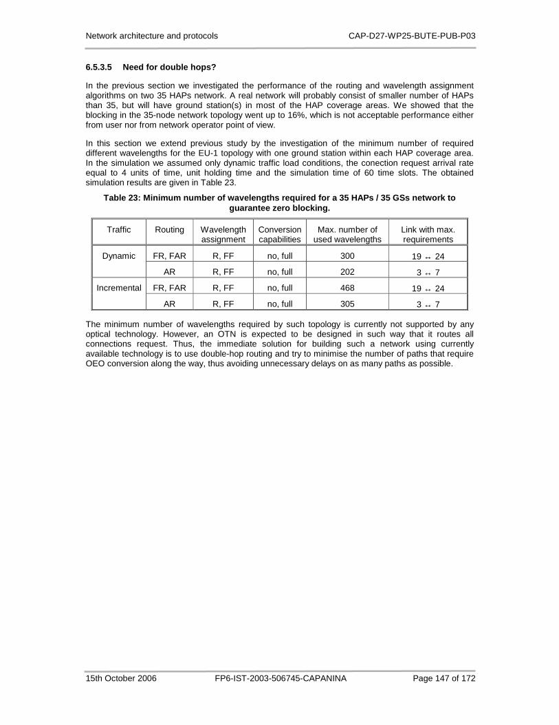
Network architecture and protocols CAP-D27-WP25-BUTE-PUB-P03
15th October 2006 FP6-IST-2003-506745-CAPANINA Page 147 of 172
6.5.3.5 Need for double hops?
In the previous section we investigated the performance of the routing and wavelength assignment algorithms on two 35 HAPs network. A real network will probably consist of smaller number of HAPs than 35, but will have ground station(s) in most of the HAP coverage areas. We showed that the blocking in the 35-node network topology went up to 16%, which is not acceptable performance either from user nor from network operator point of view.
In this section we extend previous study by the investigation of the minimum number of required different wavelengths for the EU-1 topology with one ground station within each HAP coverage area. In the simulation we assumed only dynamic traffic load conditions, the conection request arrival rate equal to 4 units of time, unit holding time and the simulation time of 60 time slots. The obtained simulation results are given in Table 23.
Table 23: Minimum number of wavelengths required fo r a 35 HAPs / 35 GSs network to guarantee zero blocking.
Traffic Routing Wavelength assignment
Conversion capabilities
Max. number of used wavelengths
Link with max. requirements
FR, FAR R, FF no, full 300 19 ↔ 24 Dynamic
AR R, FF no, full 202 3 ↔ 7
FR, FAR R, FF no, full 468 19 ↔ 24 Incremental
AR R, FF no, full 305 3 ↔ 7
The minimum number of wavelengths required by such topology is currently not supported by any optical technology. However, an OTN is expected to be designed in such way that it routes all connections request. Thus, the immediate solution for building such a network using currently available technology is to use double-hop routing and try to minimise the number of paths that require OEO conversion along the way, thus avoiding unnecessary delays on as many paths as possible.
Network architecture and protocols CAP-D27-WP25-BUTE-PUB-P03
15th October 2006 FP6-IST-2003-506745-CAPANINA Page 148 of 172
6.6 Summary
This chapter has investigated the concept of optical transport network based on a meshed HAP system with optical ULs/DLs and optical IPLs using WDM technology. For such networks it is desirable that all nodes are connected by single hop optical links avoiding any OEO conversions. However, in medium to large networks the resources available by current state of the technology might prove insufficient and double/multiple-hop conections may need to be established, requiring careful network dimensioning to avoid unnecessary complexity and delays. Taking into account physical constraints for the implementation of optical IPLs, the influence of the physical HAP network topology on wavelength routing and OTN dimensioning have been investigated analytically using two reference network topologies, the fully meshed HAP network topology and the bus network topology. These topologies represent the extreme cases in terms of the degree of physical connectivity, and consequently also in terms of the minimum number of required different wavelengths to guarantee the end-to-end optical connectivity. This has been confirmed by simulations using a HAPSSim software tool built for dimensioning and performance evaluation of HAP-based optical transport networks. With this tool we determined the wavelength requirements for three additional reference topologies, i.e. ring, circumcircled star and star topologies, and compared them to the requirements of the full mesh ad the bus topologies.
Furthermore, experimental results on a reference 21-node network showed that the blocking of connection requests in the network strongly depends on the position of a failed link within the network topology. If a link failure occurs in a network region with a high connectivity degree the resulting blocking is significantly lower than if it occurs in a region with low connectivity degree.
Finally we examined the performance of different routing and wavelength assignment schemes on two European-wide HAP network topologies consisting of 35 HAPs. We were investigating blocking of connection requests in different traffic load conditions under single-hop restriction, as well as the efficiency of utilisation of resources. We showed that the performance of the routing algorithm is by far more important than the performance of the wavelength assignment algorithm. Furthermore, the difference in blocking is higher between two routing schemes than between two assignment schemes. The experimental results also showed that for large networks double/multiple-hop routing is necessary.
In this study we were focusing on networking and topological aspects of all-optical backhaul network based on HAPs. Such network, however, brings about several challenges not addressed in this chapter, mainly concerned with establishing and maintaining optical IPLs, ULs and DLs, and with suitability of currently available optical equipment for integration in the HAP payload (in terms of power consumption, weight, volume, stabilisation, etc).

Network architecture and protocols CAP-D27-WP25-BUTE-PUB-P03
15th October 2006 FP6-IST-2003-506745-CAPANINA Page 149 of 172
7 Network Management Solutions for HAP Networks
7.1 Introduction
This chapter specifies the technical facilities that effectively help the management of HAP networks. Beyond the typical requirements of traditional management tasks, the management solutions to be proposed need to fulfil the special requirements that are HAP-specific.
SNMP is a suitable management protocol in short-term purpose because it is supported by almost vendors and using SNMP automatically means the integration with existing network technology would be easy. The further step in the specification work is the identifying and defining of new Management Information Bases (MIB) which is necessary for HAP network’s management. Besides, increasing the management reliability is identified as an important factor to be solved for the management of HAP networks.
7.2 HAP-Specific Considerations
7.2.1 HAP Flight Control Related Issues
For reliability and safety reasons conformant with the air traffic regulations, HAPs should not be used as relay devices for communications between aircrafts (or airships) and ground stations belonging to the Aeronautical Telecommunication Network (ATN) [94]. It is recommended that the ground stations for HAPs can be used by the ATN as well. In addition, the flight control information for HAPs should be separated from the normal telecommunications traffic and be carried in a separate frequency with different device. However, this document only focuses on the specification of a network management solution for the HAP telecommunications networks. But it is worth saying that some flight control information should be acquired by the management system because the flight control has a crucial impact on the provisioning of telecommunications services from HAPs. There are several solutions for obtaining the flight control information.
7.2.2 Characteristics of the Network Architecture
The specification of the network management system for CAPANINA HAP networks must take into account the specific characteristics of the HAP networks as well as the features of the network architecture.
Mobility routing: mobile IP is selected with multi level mobility support. This requires the management of several functional entities such as Mobility Anchor Point, Home Agent and Mobile Router.
QoS: a hybrid QoS architecture comprising DiffServ and IntServ is proposed to ensure QoS requirements of candidate services. Management of functionalities of this hybrid QoS architecture should be considered.
7.2.3 Control and Monitor of Communication Devices on Board
Antenna: very important factor in radio communication. In network scenarios targeted by CAPANINA project, antennas will be placed on the fixed ground stations, moving vehicles and on HAP. Staff members of network management team would be interested in several parameters of several antenna techniques (steerable antennas, smart antennas, aperture antennas).
Multiple HAP constellations: a concept of multiple HAPs covering a single coverage area sharing the same frequency bands is proposed because one HAP may not deliver enough capacity for a
Network architecture and protocols CAP-D27-WP25-BUTE-PUB-P03
15th October 2006 FP6-IST-2003-506745-CAPANINA Page 150 of 172
coverage area when the number of users increases. Then the HAP constellation solution should be managed and controlled also by network management staff.
Physical and link layer for inter-platform and back haul optical communication: the free-space optical link between a HAP and background station or another HAP differs from a conventional optical link in the terms of fluctuations, pointing, acquisition, tracking.
7.3 Specification of the Network Management
In order to select the most suitable network management system for HAP CAPANINA networks, one of the most important factors to be considered is the interworking and integration with other networks: be it satellite, fixed or cellular mobile networks. The great potential of the chosen management architecture would be its ability to enable the task of integrating management of devices from different vendors implementing different technologies.
The Telecommunications Management Network (TMN) standard [90],[91] is a hierarchical management architecture providing a largest pool of functionalities and facilities for management purposes. Management functionalities are organized in different layers of management responsibility: element, network, service and business management according to the TMN model. TMN provides an object orientation modelling technique based on ASN.1, a symmetric, scalable communication protocol (Common Management Information Protocol-CMIP -see RFC 1189), extensive generic library and support of authentication and privacy.
The OSI management system [92] is the halfway between TMN and the Internet management system. The OSI management system is based on manager-agent architecture. It models resources following object-oriented manner and its communication protocol, the CMIP, is a symmetric protocol.
As compared to TMN and OSI management system, Internet management system is a “light-weight” and “centralized” management architecture with the concept of management agents and management managers communicating with each others using the SNMP protocol. In the Internet management system, data are modelled in flat manner (SMI is a subset of ASN.1) and security and authentication are not or poorly supported. Even so, the Simple Network Management Protocol (SNMP) due to its simplicity, polling communication basis and agent-manager organization already gained a wide support from vendors as well as from users. Newer SNMP version (SNMPv3) already includes security, authentication and access support which make SNMP management architecture gaining even wider acceptance in the market.
In the short term, Internet management system should be implemented for the management of CAPANINA HAP networks because it is effective, and widely supported by almost device manufacturers. The management of HAPs which are flying object in the air certainly requires protection from intruders. Thus SNMPv3 is recommended for the HAP networks. In the long term, use of CMOT (CMIP Over TCP/IP, RFC 1189) would be the best way toward the OSI management architecture.
Both the SNMP and CMOT use the same basic concepts in describing and defining management information called Structure and Identification of Management Information (SMI) described in RFC 1155. The management information are organized in a standardized way into Management Information Base (MIB) described in RFC 1156. The SMI provides a way to describe managed object while MIB is the definition and organization of the objects themselves. Besides MIB-II (RFC 1213), we have to define new MIBs in order to operate the HAP networks. These new MIBs are organized into the following topics:
• MIB for HAP control and operation
• MIB for antennas
• MIB for HAP Constellation
• MIB for Handoff
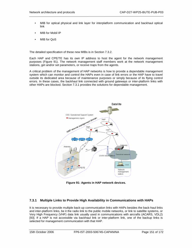
Network architecture and protocols CAP-D27-WP25-BUTE-PUB-P03
15th October 2006 FP6-IST-2003-506745-CAPANINA Page 151 of 172
• MIB for optical physical and link layer for interplatform communication and backhaul optical link
• MIB for Mobil IP
• MIB for QoS
The detailed specification of these new MIBs is in Section 7.3.2.
Each HAP and CPE/TE has its own IP address to host the agent for the network management purposes (Figure 91). The network management staff members work at the network management stations, get and/or set parameters, or receive traps from the agents.
A critical problem of the management of HAP networks is how to provide a dependable management system which can monitor and control the HAPs even in case of link errors or the HAP have to travel outside its dedicated area because of maintenance purposes or simply because of its flying control errors. In these cases, the backhaul link connected with ground gateways or inter-platform links with other HAPs are blocked. Section 7.3.1 provides the solutions for dependable management.
Figure 91: Agents in HAP network devices.
7.3.1 Multiple Links to Provide High Availability i n Communications with HAPs
It is necessary to provide multiple back-up communication links with HAPs besides the back-haul links and inter-platform links, be it the radio link to the public mobile networks, or link to satellite systems, or Very High Frequency (VHF) data link usually used in communications with aircrafts (ACARS, VDL2) [93]. If a HAP is not accessible via backhaul link or inter-platform link, one of the backup links is selected for management communication with that HAP.
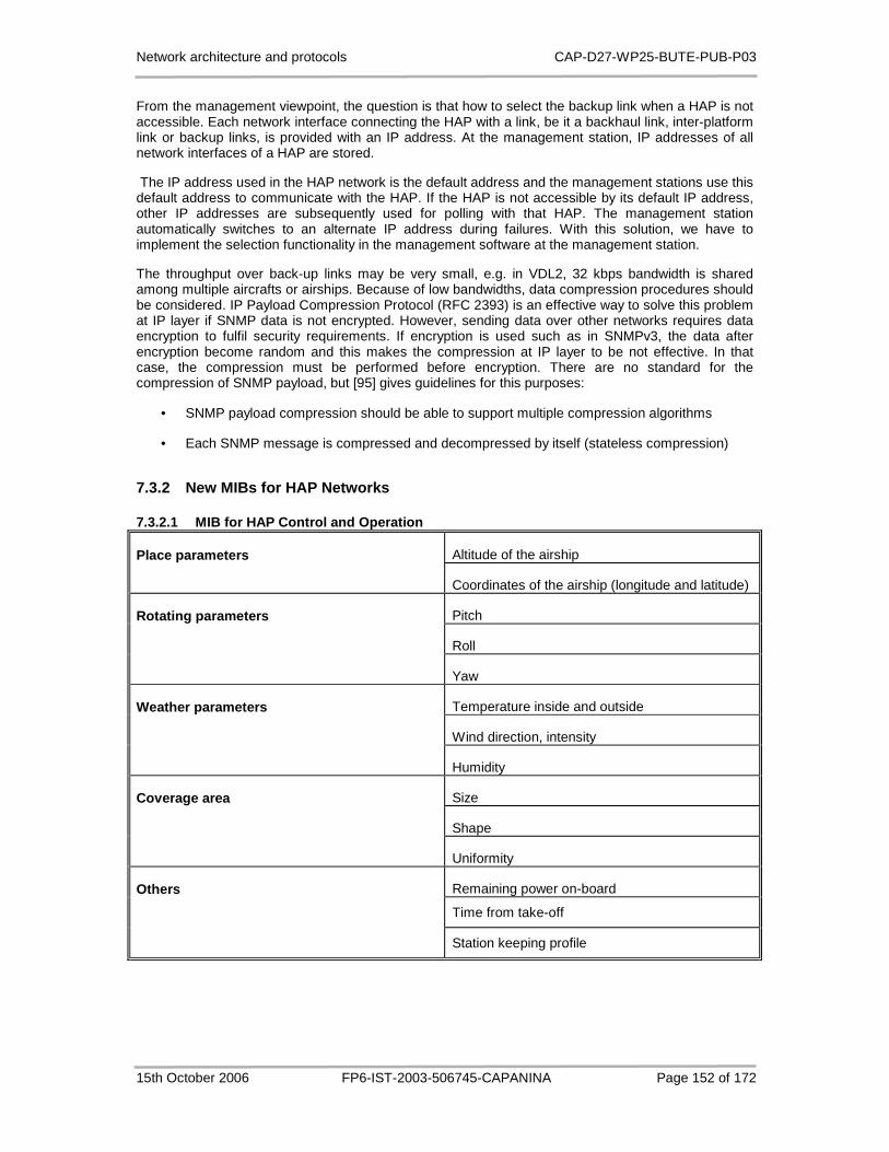
Network architecture and protocols CAP-D27-WP25-BUTE-PUB-P03
15th October 2006 FP6-IST-2003-506745-CAPANINA Page 152 of 172
From the management viewpoint, the question is that how to select the backup link when a HAP is not accessible. Each network interface connecting the HAP with a link, be it a backhaul link, inter-platform link or backup links, is provided with an IP address. At the management station, IP addresses of all network interfaces of a HAP are stored.
The IP address used in the HAP network is the default address and the management stations use this default address to communicate with the HAP. If the HAP is not accessible by its default IP address, other IP addresses are subsequently used for polling with that HAP. The management station automatically switches to an alternate IP address during failures. With this solution, we have to implement the selection functionality in the management software at the management station.
The throughput over back-up links may be very small, e.g. in VDL2, 32 kbps bandwidth is shared among multiple aircrafts or airships. Because of low bandwidths, data compression procedures should be considered. IP Payload Compression Protocol (RFC 2393) is an effective way to solve this problem at IP layer if SNMP data is not encrypted. However, sending data over other networks requires data encryption to fulfil security requirements. If encryption is used such as in SNMPv3, the data after encryption become random and this makes the compression at IP layer to be not effective. In that case, the compression must be performed before encryption. There are no standard for the compression of SNMP payload, but [95] gives guidelines for this purposes:
• SNMP payload compression should be able to support multiple compression algorithms
• Each SNMP message is compressed and decompressed by itself (stateless compression)
7.3.2 New MIBs for HAP Networks
7.3.2.1 MIB for HAP Control and Operation
Altitude of the airship Place parameters
Coordinates of the airship (longitude and latitude)
Pitch
Roll
Rotating parameters
Yaw
Temperature inside and outside
Wind direction, intensity
Weather parameters
Humidity
Size
Shape
Coverage area
Uniformity
Remaining power on-board
Time from take-off
Others
Station keeping profile

Network architecture and protocols CAP-D27-WP25-BUTE-PUB-P03
15th October 2006 FP6-IST-2003-506745-CAPANINA Page 153 of 172
7.3.2.2 MIB for Antennas
Ground antenna
Azimuth Beamwidth parameters
Elevation
Pointing accuracy azimuth Stabilisation technique
Pointing accuracy elevation
HAP antenna(s) configuration
Number of cells HAP antenna(s) configuration
Beam widths of cells (lots of data required here)
7.3.2.3 MIB for HAP Constellation
Multiple or single Constellation
Number of HAPs
Overlap characteristics No overlap/Partial overlap/Full overlap-depending on whether coverage or capacity limited. Overlap could also be used to provide diversity to increase availability.
Capacity exploitation technique Directional user antenna with sidelobe floor of at -30dB relative to boresight gain
7.3.2.4 MIB for Handoff
Inter HAP Inter HAP handoff technique
Intra HAP Intra HAP handoff technique
7.3.2.5 MIB for Optical Physical and Link Layer for Inter-platform Communication and Backhaul Optical Link
Transmit power
Exploitation of front haul
Number of ground stations
Radio
Ground station configurations

Network architecture and protocols CAP-D27-WP25-BUTE-PUB-P03
15th October 2006 FP6-IST-2003-506745-CAPANINA Page 154 of 172
Data rate 1
Availability 1
Data rate 2
Availability 2
Beamwidth - azimuth
Beamwidth - elevation
Antenna stabilisation technique
Antenna pointing accuracy - azimuth
Ground station
Antenna pointing
Beamwidth - azimuth
Beamwidth - elevation
Stabilisation technique
Pointing accuracy - azimuth
HAP antennas
Pointing accuracy -
Bit error rate
Coding and interleaving technique
Wavelength
Divergence angle
Tracking error
Transmitter
Tx divergence angle
Optical
Receiver sensitivity
Mean receive power
Receive antenna gain
Receiver
Rx aperture
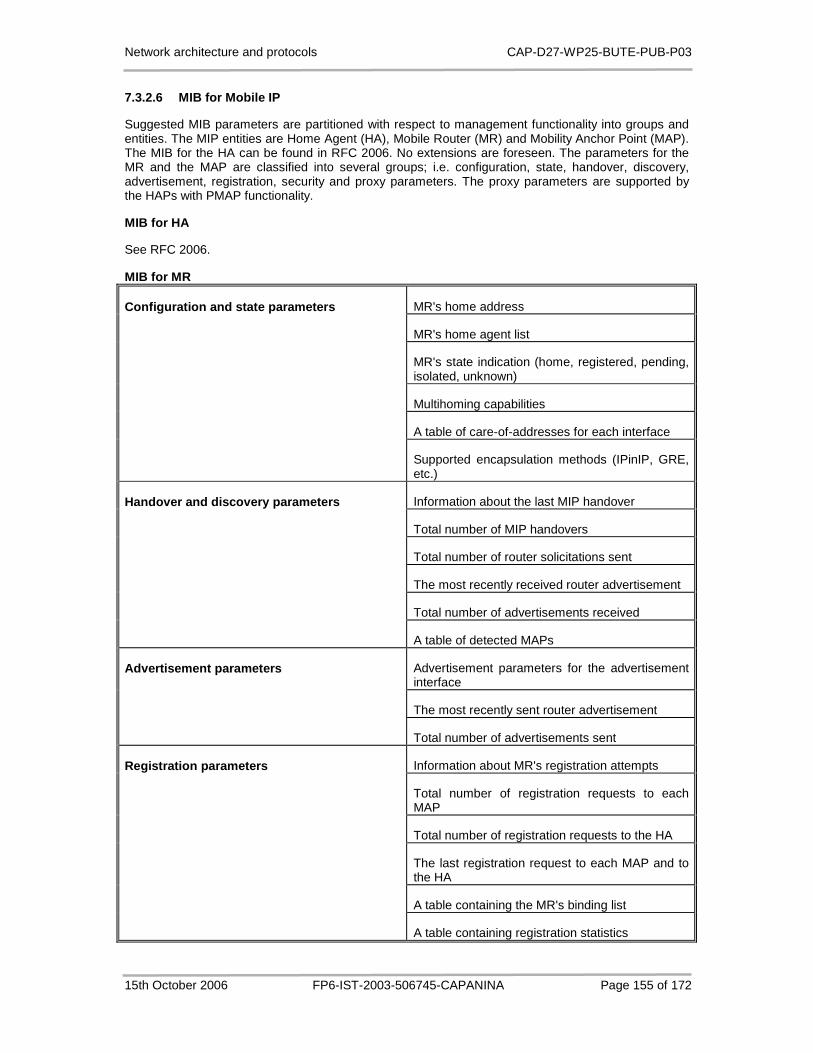
Network architecture and protocols CAP-D27-WP25-BUTE-PUB-P03
15th October 2006 FP6-IST-2003-506745-CAPANINA Page 155 of 172
7.3.2.6 MIB for Mobile IP
Suggested MIB parameters are partitioned with respect to management functionality into groups and entities. The MIP entities are Home Agent (HA), Mobile Router (MR) and Mobility Anchor Point (MAP). The MIB for the HA can be found in RFC 2006. No extensions are foreseen. The parameters for the MR and the MAP are classified into several groups; i.e. configuration, state, handover, discovery, advertisement, registration, security and proxy parameters. The proxy parameters are supported by the HAPs with PMAP functionality.
MIB for HA
See RFC 2006.
MIB for MR
MR's home address
MR's home agent list
MR's state indication (home, registered, pending, isolated, unknown)
Multihoming capabilities
A table of care-of-addresses for each interface
Configuration and state parameters
Supported encapsulation methods (IPinIP, GRE, etc.)
Information about the last MIP handover
Total number of MIP handovers
Total number of router solicitations sent
The most recently received router advertisement
Total number of advertisements received
Handover and discovery parameters
A table of detected MAPs
Advertisement parameters for the advertisement interface
The most recently sent router advertisement
Advertisement parameters
Total number of advertisements sent
Information about MR's registration attempts
Total number of registration requests to each MAP
Total number of registration requests to the HA
The last registration request to each MAP and to the HA
A table containing the MR's binding list
Registration parameters
A table containing registration statistics

Network architecture and protocols CAP-D27-WP25-BUTE-PUB-P03
15th October 2006 FP6-IST-2003-506745-CAPANINA Page 156 of 172
Security association table
Particular mobility security association
Total number of security violations
MIP security violation table
Security parameters
Information about one particular security violation
MIB for MAP
Configuration parameters Supported encapsulation methods (IPinIP, GRE, etc.)
Advertisement parameters for the advertisement interface
The most recently sent MAP advertisement
Advertisement parameters
Total number of MAP advertisements sent
Total number of registration requests received Registration parameters
A table containing binding cache entries
PMAP multicast group address
Total number of SYNC requests received
The last SYNC request received
Total SYNC requests sent
Total SYNC requests sent
Proxy parameters
The last SYNC request sent
7.3.2.7 MIB for QoS
IP Address of Bandwidth Broker Bandwidth broker parameters
Port number of Bandwidth Broker
Bandwidth share of Guaranteed Service Bandwidth share
Bandwidth share of Controlled-load Service
IntServ-DiffServ mapping matrix
IntServ-LL QoS mapping matrix
Traffic class mapping
DiffServ-LL QoS mapping matrix
User buffer size
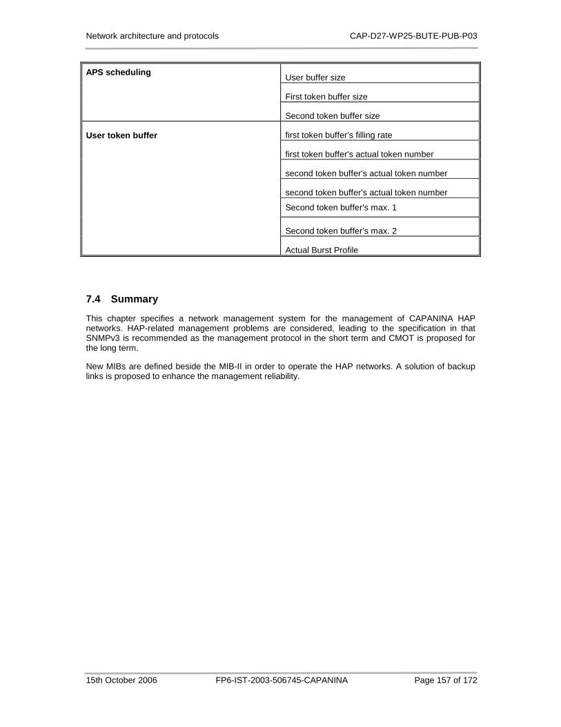
Network architecture and protocols CAP-D27-WP25-BUTE-PUB-P03
15th October 2006 FP6-IST-2003-506745-CAPANINA Page 157 of 172
User buffer size
First token buffer size
APS scheduling
Second token buffer size
first token buffer's filling rate
first token buffer's actual token number
second token buffer's actual token number
second token buffer's actual token number
Second token buffer's max. 1
Second token buffer's max. 2
User token buffer
Actual Burst Profile
7.4 Summary
This chapter specifies a network management system for the management of CAPANINA HAP networks. HAP-related management problems are considered, leading to the specification in that SNMPv3 is recommended as the management protocol in the short term and CMOT is proposed for the long term.
New MIBs are defined beside the MIB-II in order to operate the HAP networks. A solution of backup links is proposed to enhance the management reliability.

Network architecture and protocols CAP-D27-WP25-BUTE-PUB-P03
15th October 2006 FP6-IST-2003-506745-CAPANINA Page 158 of 172
8 Summary and Conclusions
This deliverable has investigated several HAP or even CAPANINA operating scenario specific networking aspects. It follows the concept of providing the basic assumptions, defining requirements for the network architecture, identifying specific problems and giving suitable solutions. In particular, the issues identified as those requiring special attention within the workpackage WP2.5 include: QoS implementation and service provisioning for the mobile access network; network layer mobility support; the mechanisms for load balancing, error detection and recovery; network management solutions for HAP networks; and networking in all-optical HAP networks.
In Chapter 2, the basic assumptions taken into consideration in this study were presented: IEEE 802.16-SC is assumed to be the wireless access technology and IP be the network layer protocol. The use of IP as the network layer protocol, supported by numerous existing standards (RFCs), simplified the space of possible problems and solutions. Three basic IP-based architectures have been considered for further investigation: All-IP, MPLS and All-Optical architectures. With the requirements and assumptions we identify the primary problems and gives solutions for each of them. The requirements were identified in CAPANINA’s Deliverable D13 and herein shortly summarised. A network architecture satisfying these requirements can deliver the candidate applications and services listed in CAPANINA’s Deliverable D1. The basic assumptions, especially the assumption about adopting IP as the network layer protocol, have important impacts on the set of requirements. By analysing these impacts, the set of requirements was reduced to solving the following problems:
• Quality of Service.
• Suitable AAA standards.
• Routing or switching protocols capable for quick error detections an recovery.
• Mobility management.
• Network management.
• Operational Support System.
• Design of CPE/TE.
• Security and key management.
Chapter 3 provides solutions for open problems related to the provision of QoS for CAPANINA HAP networks: (1) A packet scheduling algorithm called Adaptive Profile Scheduling (APS) was proposed with the aim to improve system throughput (with normal parameter setting, simulation results showed that APS could improve the system throughput by 21%) while guaranteeing minimum rates for users and long-term fairness. Using APS as the main element we showed how to implement DiffServ in the downlink and implement IEEE 802.16’s link layer QoS specification. (2) Solutions were proposed to adapt the measurement-based admission control algorithms to the IEEE 802.16 environment where the overall link bit rate is variable in time. By simulation we showed which is the best solution for the Simple Sum admission control algorithm. (3) We showed how to carry RSVP signalling messages over wireless access link by mapping them directly to DSA-req messages. For the mobile scenario, a RSVP re-establishment solution using proxies was proposed to renegotiate the existing IntServ connections. We also considered the solutions to carrying IntServ and DiffServ traffic together on the access downlink. (4) The comparative analysis of the combinations of DiffServ, ToS routing and MPLS approach has shown that mixing strategies for both optimizing the forwarding scheme, like DiffServ does, and the routing algorithm, like in ToS routing, is a good approach to provide QoS in a network.
Chapter 4 describes the network architecture implications of using multiple platforms with overlaid coverage areas by introducing additional network elements with additional functionality. Two different architectures for load balancing are proposed. They differ with regard to complexity of additional elements, which should be installed in the system. At the basic utilisation of multiple HAPs, additional network element is added at user's premises, allowing the capacity increase and load balancing on
Network architecture and protocols CAP-D27-WP25-BUTE-PUB-P03
15th October 2006 FP6-IST-2003-506745-CAPANINA Page 159 of 172
outbound connections only. The advanced utilisation of multiple HAPs is more complex and requires also the load balancing router at the gateway, allowing the load balancing in both directions, outbound and inbound. Also in this chapter, network errors were categorized into 3 groups and 3 MPLS-based scenarios were investigated in terms of error detection and recovery, in particular: which type of error can be detected, how fast and simple are the related detection and recovery mechanisms. It was concluded that the third scenario comprising GMPLS and MPLS would be the best option which can utilize the advantages and eliminate the disadvantages of the first two scenarios: the GMPLS and MPLS scenario.
Chapter 5 analyzed network layer mobility support in specific environment involving communications between high speed vehicles and HAP network. Some original contributions were proposed. The problem of routing to a mobile node was split into micro and macro-mobility parts. Apart from that division, access mobility was considered as the lowest level of mobility. Mobility within a single HAP was proposed to be implemented on the link layer, i.e. as access mobility, because loose coupling with network layer mobility enables exploitation of specific HAP access technology. IP-based micro-mobility protocols were proposed for the inter-platform movements. The main concepts involved into mobility support, such as MIP, HMIP and mobile routers were analyzed in the HAP-to-train scenario. Proxy MAP functionality in HMIP domain nodes was proposed in order to tackle intra-domain path optimization. This HMIP capability is lost if multi-level MIP is required and NEMO technology is used. Numerical evaluation of mean route length in an HMIP domain with multiple layers demonstrated the effectiveness of the proposed solution. Furthermore, we showed that careful selection of home agent location may significantly reduce the network burden due to the large HAP coverage area and expected localized mobility. The placement optimization of MIP home agent entity in this particular environment was proposed and evaluated. Analysis of multihoming configurations in the context of HAP networks and mobile routers was provided next. Multihoming support can provide route efficiency, fast handover between HAP and terrestrial links, as well as alleviate connectivity problem during NLOS conditions if quasi-deterministic route patterns are in place. We showed that multiple HAs increase throughput and reduce load on scarce wireless links. Simultaneous usage of multiple access interfaces is beneficial in terms of handoff efficiency.
In Chapter 6 we focus on networking and topological aspects of all-optical backhaul network based on HAPs. We investigated the concept of optical transport network and its application to CAPANINA HAP network, based on the assumption that free-space optics can be used both on inter-platform links and backhaul uplinks and downlinks. Various technologies and concepts supporting optical transport network are addressed, focusing on wavelength division multiplex concept and the wavelength routing. The main attention was given to the impact of physical network topology to the number of different required wavelengths to maintain all-optical paths between all nodes in the network. Different topologies have been taken into consideration, from basic regular topologies to representative general topologies, and were analysed analytically and numerically in terms of network characteristics and wavelength requirements. We also provide simulation results investigating the effect of link failure and the performance of different routing and wavelength assignment schemes, in particular showing that the performance of the routing algorithm is by far more important than the performance of the wavelength assignment algorithm.
Chapter 7 specifies a network management system for the management of CAPANINA’s HAP networks. HAP-related management problems are considered, leading to the specification in that SNMPv3 is recommended as the management protocol in the short term and CMOT is proposed for the long term. New MIBs are defined beside the MIB-II in order to operate the HAP networks. A solution of backup links is proposed to enhance the management reliability.
The work in WP2.5 could not solve all the problems related to the HAP system network architecture due to limited time and human resources. Thus, some of the identified problems still remain open such as mobility issues when MPLS is used, authentication and security schemes, suitable AAA concept, operational support system, the design of CPE/TE, security and key management problems. Nonetheless, we believe that the problems chosen for detailed investigation in WP2.5 represent the subset of HAP-specific networking issues that are particularly relevant for the specific CAPANINA high-speed train operating scenario, and thus needed to be solved first.

Network architecture and protocols CAP-D27-WP25-BUTE-PUB-P03
15th October 2006 FP6-IST-2003-506745-CAPANINA Page 160 of 172
9 References
[1] D. D. Luong, Nam H. Do, Gergo Buchholcz, Tien V. Do, Packet Fair Scheduling for Wireless Channels with Adaptive Burst Profile, International Workshop on High Altitude Platform Systems -WHAPS 05, Athens, Greece, September. 2005.
[2] D. D. Luong, Gergo Buchholcz, Tien V. Do, Scheduling for Broad-Band Wireless Access with Adaptive Burst Profiles, International Wireless Summit 2005, Denmark, September 2005
[3] D. D Luong. Nam H. Do, Cross-layer design of a packet scheduling algorithm, Softcom 2006, Split - Dubrovnik, Croatia, September 29th – October 1st, 2006
[4] D. D. Luong, Anh P. M Tran, Tien V. Do, Guard Channel CAC Algorithm for High Altitude Platform Networks, HET-NETs '06 Int. Working Conference, Ilkley, West Yorkshire, England, 11th - 13th, September 2006
[5] R. Novak. Proxy home agents for route optimization in HAP networks. WSEAS Trans. Comput., 2004, vol. 3, pp. 1819-1824.
[6] R. Novak. Proxy MAP for intra-domain route optimization in hierarchical mobile IP. IEICE trans. commun., 2006, vol. E89-B, no. 2, pp. 472-481.
[7] R. Novak. Mobility support in HAP networks. In: Proceedings of the 30th EUROMICRO Conference, Rennes (France), September 2004, pp. 13-14.
[8] R. Novak. AII-IP architecture for HAP networks : mobility issues. In: Proc. of International Conference on Software, Telecommunications and Computer Networks SOftCOM 2004, Split-Dubrovnik, Croatia, Venice, Italy, October 10-13,2004, pp. 64-68.
[9] R. Novak, M. Mohorčič, Mihael, ŠVIGELJ, Aleš, KANDUS, Gorazd. IP mobility architecture for high altitude platform networks. In: Proc. Of International Workshop on High Altitude Platform Systems - WHAPS '05, Athens, Greece, September 5, 2005.
[10] A. Vilhar, R. Novak. Home agent placement optimization for HAP-based network mobility. In: Proc. of International Workshop on Satellite and Space Communications (ISWCS 2005), September 8-9, 2005, Siena, Italy.
[11] A. Vilhar, R. Novak, G. Kandus. Multihoming benefits for network mobility in HAP networks. In: Proc. of 3rd Advanced Satellite Mobile Systems Conference (ASMS 2006), 29-31 May 2006, Herrsching am Ammersee, Munich, Germany.
[12] T. Javornik, M. Mohorčič, A. Švigelj, I. Ozimek, and G. Kandus, "Adaptive Coding and Modulation for Mobile Wireless Access via High Altitude Platforms", Wireless Personal. Communications, Vol. 32, Issue 3-4, February, 2005, pp. 301-317.
[13] C. Fortuna, A. Vilhar and M. Mohorčič, “HAP based optical transport network design”, in Proc. 15th International Electrotechnical and Computer Science Conference (ERK 2006), 25-27 September, 2006, Portorož, Slovenia.
[14] M. Mohorčič, A. Vilhar, M. Beriolli, A. Donner M. Werner, ”Optical Transport Network Based on a Meshed HAP System With Interplatform Links”, in Proc. Advanced Satellite Mobile Systems (ASMS) Conference 2006, 29-31 May, 2006, Herrsching, Germany.
[15] T. Celcer, G. Kandus, T. Javornik, M. H. Capstick, M. Mohorčič, "Analysis of HAP Propagation Channel Measurement Data", in Proc. 15th IST Mobile and Wireless Communications Summit 2006, Myconos, Greece, June 4-8, 2006.
[16] J. Horwath, M. Knapek, M. Brechtelsbauer, H. Henniger, B. Wilkerson, B. Epple, “Optical Communication for High Altitude Platforms: the Stratospheric Optical Payload Experiment”, in Proc. Advanced Satellite Mobile Systems (ASMS) Conference 2006, 29-31 May, 2006, Herrsching, Germany.

Network architecture and protocols CAP-D27-WP25-BUTE-PUB-P03
15th October 2006 FP6-IST-2003-506745-CAPANINA Page 161 of 172
[17] IST CAPANINA D1 deliverable, Applications and Services for Broadband HAP Delivery, Jan. 2004.
[18] IST CAPANINA D9 deliverable, Selection of Broadband Communication Standard for High-Speed Mobile Scenario, Jan. 2005.
[19] IST CAPANINA D13 deliverable, General Network Architecture Requirements, May. 2005.
[20] The Network Simulator - ns-2. http://www.isi.edu/nsnam/ns/.
[21] A. K. Parekh, R. G. Gallager, “A Generalized Processor Sharing Approach to Flow Control in Integrated Services Networks: The Single-Node Case,” IEEE INFOCOM’ 92, Vol. 2, pp. 915-924, May 1992.
[22] H. Zhang, “Service disciplines for guaranteed performance service in packet switching networks”, In Proceedings of the IEEE, Vol. 83, no. 10, pp. 1374-1396, October 1995.
[23] T. Nadagopal, S. Lu and V. Bharghavan, “A unified architecture for design and evaluation of the wireless fair queuing algorithms”, MobileCom’99 – Proceedings of the Fifth Annual ACM/IEEE International Conference on Mobile Computing and Networking, pp. 132 –142, August 1999.
[24] Yaxin Cao and Victor O. K. Li. “Scheduling Algorithms in Broadband Wireless Networks”. In Proceedings of the IEEE, Vol. 89, no. 1, January 2001.
[25] W.K. Wong, H. Tang and V.C.M. Leung, “Token Bank Fair Queuing: A new scheduling algorithm for wireless multimedia services”, Intel Journal of Communication Systems, Vol. 17, pp. 591-614, August 2004.
[26] H.S. Wang and N. Moayeri. “Modelling, Capacity, and Joint Source/Channel Coding for Rayleigh Fading Channels”. In Proceedings of 43rd IEEE Vehicular Technology Conference, pp. 473479, 1993.
[27] Lingjie Li, Octavian Sarca, “FEC Performance with ARQ and Adaptive Burst Profile Selection”. IEEE 802.16 working document, 2001.
[28] R. Jain and D. Chiu and W. Haweu, “A Quantitative Measure of Fairness and Discrimination for Resource Allocation in Shared Computer System”. Research Report, TR-301, September 1984.
[29] Ram Chakka and Tien V. Do, The MM CPP/GE/c/L G-Queue with Heterogeneous Servers: Steady State Solution and an Application to Performance Evaluation, Accepted for Performance Evaluation, 2006.
[30] Jianfeng Chen, Wenhua Jiao, Qian Guo, “An Integrated QoS Control Architecture for IEEE 802.16 Broadband Wireless Access Systems”, IEEE Globecom - 05, St. Louis, Missouri, USA from 28 November to 2 December.
[31] S. Paskalis, A. Kaloxylos, E. Zervas, and L. Merakos. An Efficient RSVP--Mobile IP Interworking Scheme. Journal on Special Topics in Mobile Networking and Applications (MONET), 8(3), June 2003. http://citeseer.ist.psu.edu/paskalis03efficient.html.
[32] Jianfeng Chen, Wenhua Jiao, Hongxi Wang, “A Fair Scheduling for IEEE 802.16 Broadband Wireless Access Systems”, ICC2005, May 16-20, Souel, Korea.
[33] Hawa, M.; Petr, D.W.,Quality of service scheduling in cable and broadband wireless access systems, Tenth IEEE International Workshop on Quality of Service, p247-255, 2002.
[34] K. Wongthavarawat, and A. Ganz, “Packet Scheduling for QoS Support in IEEE 802.16 Broadband Wireless Access Systems”, International Journal of Communication Systems, Vol. 16, p81-96, 2003.
[35] J. Wroclawski et al., “Integrated Services Mappings for Differentiated Services Networks, Internet Draft, IETF, February 2001.”
Network architecture and protocols CAP-D27-WP25-BUTE-PUB-P03
15th October 2006 FP6-IST-2003-506745-CAPANINA Page 162 of 172
[36] A. Pereira et al, "Dynamic mapping between the Controlled-Load IntServ service and the Assured Forward DiffServ PHB", in Proc. of the HSNMC2003, pp. 1-10, Portugal, July-2003.
[37] Zoubir Mammeri. End-to-end QoS mapping in IntServ-over-DiffServ architectures. Dans: 6th IEEE International Conference on High Speed Networks and Multimedia Communications, Estoril (Portugal), 23-25 July 2003. LNCS 2720 - Springer Verlag, p. 31-40.
[38] IEEE Standard for Local and metropolitan area networks Part 16: Air Interface for Fixed Broadband Wireless Access Systems, October 2004.
[39] C. H. Shih, C. C. Liao, “A Transparent QoS Mechanism to Support IntServ/DiffServ Networks”, IEEE Consumer Communications and Networking Conference (CCNC), Las Vegas, NV, Jan 2004.
[40] R.Mameli, S.Salsano, “Use of COPS for Intserv operations over Diffserv: Architectural issues, Protocol design and Test-bed implementation”, IEEE ICC 2001, Helsinki, June 11-14, 2001.
[41] B.F.Koch (editor) C.Prehofer, I.S.Venieris, G.Mamais, G.Politis, G.Eichler, M.A.Barba, R.Cocca, S.Salsano, H.Hussmann, F.Fünfstück, T. V. Do, Chapter: “Internet Service Architectures and ATM – The ELISA Approach”.
[42] Neilson, Rob, Jeff Wheeler, Francis Reichmeyer, and Susan Hares, "A Discussion of Bandwidth Broker Requirements for Internet2 Qbone Deployment", ver. 0.7, August 1999, http://www.merit.edu/working.groups/i2-qbone-bb/doc/BB_Req7.pdf.
[43] HE-079-WP5-UNY-SP-01, “Outline System Specification for the Broadband Application, IST HELINET Specification”, Feb. 2003.
[44] S. Jamin, S. Shenker, and P. Danzig. “Comparison of Measurement-based Admission Control Algorithms for Controlled-Load Service”. In Proceedings of IEEE INFOCOM '97, Kobe, Japan, April 1997
[45] Jamin. S., Danzig. P.B., Shenker. S and Zhang. L., A Measurement-based Admission Control Algorithm for Integrated Services Packet Networks., Proc. SIGCOMM '95, 1995.
[46] G. Ahn and W. Chun, ìDesign and Implementation of MPLS Network Simulator supporting LDP and CR-LDP,î in Proceedings 8th IEEE International Conference on Networks 2000 (ICON 2000), Singapore, Sept. 2000.
[47] L. Kleinrock, Queuing Systems Volume I: Theory. Wiley Interscience Publication, John Wiley and Sons, Inc., 1976, vol. 1.
[48] D. Bertsekas and R. Gallager, Data Networks. Prentice-Hall, Inc., 1987.
[49] http://www.Cisco.com
[50] http://broadband.nildram.net
[51] Miha Mohorcic, Carolina Fortuna, Networking in all-optical backhaul network (CAP-0436-WP25-JSI-CON-01).
[52] A. Campbell, J. Gomez, S. Kim, A. Valko, C. Wan, and Z. Turanyi, "Design implementation and evaluation of cellular IP", IEEE Pers. Commun., vol.7, no.4, pp.42-49, 2000.
[53] R. Ramjee, K. Varadhan, L. Salgarelli, S. Thuel, S. Wang, and T.L. Porta, "HAWAII: A domain-based approach for supporting mobility in wide-area wireless networks", IEEE/ACM Trans. Netw., vol.10, no.3, pp.396-410, June 2002.
[54] S. Das, A. Misra, P. Agrawal, and S. Das, "TeleMIP: Telecommunication enhanced mobile IP architecture for fast intra-domain mobility", IEEE Pers. Commun., vol.7, no.4, pp.50-58, 2000.
[55] C. Castellucia, "HMIPv6: A hierarchical mobile IPv6 proposal", ACM Mobile Comput. Commun. Rev., vol.4, no.1, pp.48-59, 2000.

Network architecture and protocols CAP-D27-WP25-BUTE-PUB-P03
15th October 2006 FP6-IST-2003-506745-CAPANINA Page 163 of 172
[56] N. Banerjee, W. Wu, K. Basu, and S. Das, "Analysis of SIP-based mobility management in 4G wireless networks", Comput. Commun., vol.27, no.8, pp.697-707, 2004.
[57] D. Johnson, C. Perkins, and J. Arkko, "Mobility support in IPv6'', Internet Draft, draft-ietf-mobileip-ipv6-24.txt, IETF, June 2003.
[58] T. Ernst, A. Olivereau, L. Bellier, C. Castelluccia, and H. Lach, "Mobile networks support in mobile IPv6 (prefix scope binding updates)", Internet Draft, draft-ernst-mobileip-v6-network-03.txt, NEMO Working Group, 2002.
[59] V. Devarapalli, R. Wakikawa, A. Petrescu, and P. Thubert, "Nemo basic support protocol", Internet Draft, draft-ietf-nemo-basic-support-01.txt, NEMO Working Group, 2003.
[60] T. Ernst, "Network mobility support goals and requirements", Internet Draft, draft-ietf-nemo-requirements-01.txt, IETF, 2003.
[61] P. Thubert and M. Molteni, "IPv6 reverse routing header and its application to mobile networks", Internet Draft, draft-thubert-nemo-reverse-routing-header-04.txt, NEMO Working Group, 2004.
[62] T. Kniveton, J. Malinen, V. Devarapalli, and C. Perkins, "Mobile router tunneling protocol", Internet Draft, draft-kniveton-mobrtr.txt, NEMO Working Group, 2002.
[63] Y. Takagi, H. Ohnishi, K. Sakitani, K. Baba, and S. Shimojo, "Route optimization methods for network mobility with mobile IPv6", IEICE Trans. Commun., vol.E87-B, no.3, pp.480-489, 2004.
[64] H. Ohnishi, K. Sakitani, and Y. Takagi, "HMIP based route optimization method in a mobile network", Internet Draft, draft-ohnishi-nemo-ro-hmip-00.txt, NEMO Working Group, 2003.
[65] E. Perera, V. Sivaraman, and A. Senevirtane, "Survey on network mobility support", ACM Mobile Comput. Commun. Rev., vol.8, no.2, pp.7-19, 2004.
[66] R. Wakikawa, S. Koshiba, K. Uehara, and J. Murai, "ORC: Optimized route cache management protocol for network mobility", Proc. of 10th Int. Conf. on Telecommunications ICT, Tahiti Papeete, French Polynesia, vol.2, pp.1194-1200, February 2003.
[67] J. Jeong, K. Lee, J. Park, and H. Kim, "ND-Proxy based route and DNS optimizations for mobile nodes in mobile network", Internet Draft, draft-jeong-nemo-ro-ndproxy-02.txt, IETF, 2004.
[68] K. Lee, J. Jeong, J. Park, and H. Kim, "Route optimization for mobile nodes in mobile network based on prefix delegation", Internet Draft, draft-leekj-nemo-ro-pd-02.txt, IETF, 2004.
[69] E. Perera, R. Hsieh, and A. Seneviratne, "Extended network mobility support", Internet Draft, draft-perera-nemo-extended-00.txt, IETF, 2003.
[70] E. Perera, A. Seneviratne, and V. Sivaraman, "OptiNets: An architecture to enable optimal routing for network mobility", Proc. of Int. Workshop on Wireless Ad-hoc Networks, Oulu, Finland, May 2004.
[71] J. Na, J. Choi, S. Cho, and C. Kim, "A unified route optimization scheme for network mobility", Proc. of Int. Conf. on Personal Wireless Communications, Delft, Netherlands, LNCS, vol.3260, pp.29-38, September 2004.
[72] C. Barakat, E. Altman, and W. Dabbous, "On TCP performance in a heterogeneous network: A survey", IEEE Commun. Mag., vol.38, no.1, pp.40-46, 2000.
[73] OPNET modeler - network performance evaluation and system architecture development", http://www.opnet.com/.
[74] C. Ng, E. Paik, T. Ernst, "Analysis of multihoming in network mobility support", Internet Draft, draft-ietf-nemo-multihoming-issues-02.txt, NEMO, 2005.
[75] N. Montavont, R. Wakikawa, T. Noel, T. Ernst, "Problem statement of multihomed mobile node", Internet Draft, draft-montavont-mobileip-multihoming-pb-statement-00.txt, IETF, 2003.
Network architecture and protocols CAP-D27-WP25-BUTE-PUB-P03
15th October 2006 FP6-IST-2003-506745-CAPANINA Page 164 of 172
[76] N. Montavont, R. Wakikawa, T. Ernst, C. Ng, and K. Kuladinithi, “Analysis of multihoming in mobile IPv6”, Internet Draft, draft-montavont-mobileip-multihoming-pb-statement-04.txt, IETF, 2005.
[77] R. Wakikawa, V. Devarapalli, P. Thubert, "Inter home agents protocol (HAHA)", Internet Draft, draft-wakikawa-mip6-nemo-haha-01.txt, NEMO, 2004.
[78] T. Bu, L. Gao, and D. Towsley, “On routing table growth”, ACM SIGCOMM Comput. Commun. Rev., vol. 32, no. 1, p. 11, 2002.
[79] C. Pârvu, “Telecommunication System Based on High Altitude Platforms”, Diploma thesis, Technical University of Cluj-Napoca, 29th June 2006.
[80] D. D. Luong, T. V. Do, R. Novak, A. Vilhar, M. Mohorčič, C. Fortuna, Development of Simulation Models, FP6-IST-2003-506745 CAPANINA Milestone report, CAP-0110-WP25-BUTE-CON-03, 26th June 2006.
[81] D. Giggenbach, R. Purvinskis, M. Werner, M. Holzbock, ”Stratospheric Optical Interplatform Links for High Altitude Platforms”, in Proc. 20th AIAA International Communication Satellite Systems Conference and Exhibit, Montreal, Quebec, May 12-15, 2002.
[82] FP6 IST Project CAPANINA (FP6 IST-2003-506745), “Communications from Aerial Platform Networks Delivering Broadband Communications for All”, Available: http://www.capanina.org/.
[83] G. M. Djuknic, J. Freidenfelds, and Y. Okunev, “Establishing Wireless Communications Services via High-Altitude Aeronautical Platforms: A Concept Whose Time Has Come?,” IEEE Commun. Mag., vol. 35, no. 9, Sept. 1997, pp. 128–35.
[84] H. Zang, J. Jue, and B. Mukherjee, ”A Review of Routing and Wavelength Assignment Approaches for Wavelength Routed Optical WDM Networks”, Optical Networks Magazine, January 2000, Volume 1, pp. 47-60.
[85] J. A. Tompkins, J. R. Jacobs, ”Bridging The Last Mile Access Network Wireline Architectures”, Corning WP6300, January 2001.
[86] J. Innes, B. Mukherjee, ”Sparse Wavelength Conversion in Wavelength Routed WDM Optical Networks”, Photonic Network Communications, Kluwer Academic Publishers, Boston, November 1999, Volume 1, pp. 183-205.
[87] S. Ramamurthy, B. Mukherjee, ”Fixed-Alternate Routing and Wavelength Conversion in Wavelength-Routed Optical Networks”, IEEE/ACM Transactions on Networking (TON), vol.10, no.3, pp.351-367, June 2002.
[88] S. S. Dixit, ”IP over WDM - Building the Next Generation Optical Internet”, John Wiley & Sons, 2003
[89] U. Drčić, G. Kandus, M. Mohorčič, T. Javornik, ”Interplatform link requirements in the network of high altitude platforms”, in Proc. 19th AIAA International Communication Satellite Systems Conference and Exhibit, Toulouse, France, April 17-20, 2001.
[90] The Global TMN Market: Managing Telecom Networks in the 21st Century, White paper, John Hutchison, Venture Development Corporation, 1999. November
[91] CCITT: "Recommendation M.3010, Principles for a Telecommunications Management Network", Geneva 1996
[92] ISO, Information Processing Systems, Open Systems Interconnection, Basic Reference Model, Part 4: Management Framework, International Organization for Standardization, International Standard 7498-4, 1991
[93] T.L. Signore, M. Girard, The Aeronautical Telecommunication Network (ATN), Military Communications Conference, Boston, MA, USA, Oct 1998.
Network architecture and protocols CAP-D27-WP25-BUTE-PUB-P03
15th October 2006 FP6-IST-2003-506745-CAPANINA Page 165 of 172
[94] Aeronautical Telecommunication Network, http://www.icao.int
[95] J. Schoenwaelder, SNMP Payload Compression, http://www.ibr.cs.tu-bs.de/projects/nmrg/draft-irtf-nmrg-snmp-compression-01.txt, Apr 2001.
[96] H.S. Wang and N. Moayeri. “Modelling, Capacity, and Joint Source/Channel Coding for Rayleigh Fading Channels”. In Proceedings of 43rd IEEE Vehicular Technology Conference, pp. 473479, 1993.
[97] Jianfeng Chen, Wenhua Jiao, Qian Guo, “An Integrated QoS Control Architecture for IEEE 802.16 Broadband Wireless Access Systems”, IEEE Globecom - 05, St. Louis, Missouri, USA from 28 November to 2 December.
[98] J. Wroclawski et al., “Integrated Services Mappings for Differentiated Services Networks, Internet Draft, IETF, February 2001.”
[99] A. Pereira et al, "Dynamic mapping between the Controlled-Load IntServ service and the Assured Forward DiffServ PHB", in Proc. of the HSNMC2003, pp. 1-10, Portugal, July-2003.
[100] Zoubir Mammeri. End-to-end QoS mapping in IntServ-over-DiffServ architectures. Dans: 6th IEEE International Conference on High Speed Networks and Multimedia Communications, Estoril (Portugal), 23-25 July 2003. LNCS 2720 - Springer Verlag, p. 31-40
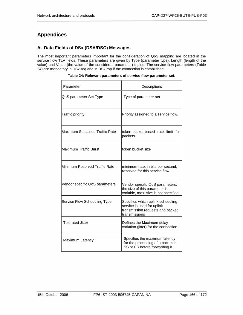
Network architecture and protocols CAP-D27-WP25-BUTE-PUB-P03
15th October 2006 FP6-IST-2003-506745-CAPANINA Page 166 of 172
Appendices
A. Data Fields of DSx (DSA/DSC) Messages
The most important parameters important for the consideration of QoS mapping are located in the service flow TLV fields. These parameters are given by Type (parameter type), Length (length of the value) and Value (the value of the considered parameter) triples. The service flow parameters (Table 24) are mandatory in DSx-req and in DSx-rsp if the connection is established.
Table 24: Relevant parameters of service flow param eter set.
Parameter Descriptions
QoS parameter Set Type Type of parameter set
Traffic priority Priority assigned to a service flow.
Maximum Sustained Traffic Rate token-bucket-based rate limit for packets
Maximum Traffic Burst token bucket size
Minimum Reserved Traffic Rate minimum rate, in bits per second, reserved for this service flow
Vendor specific QoS parameters Vendor specific QoS parameters, the size of this parameter is variable, max. size is not specified
Service Flow Scheduling Type Specifies which uplink scheduling service is used for uplink transmission requests and packet transmissions
Tolerated Jitter Defines the Maximum delay variation (jitter) for the connection.
Maximum Latency Specifies the maximum latency for the processing of a packet in SS or BS before forwarding it.
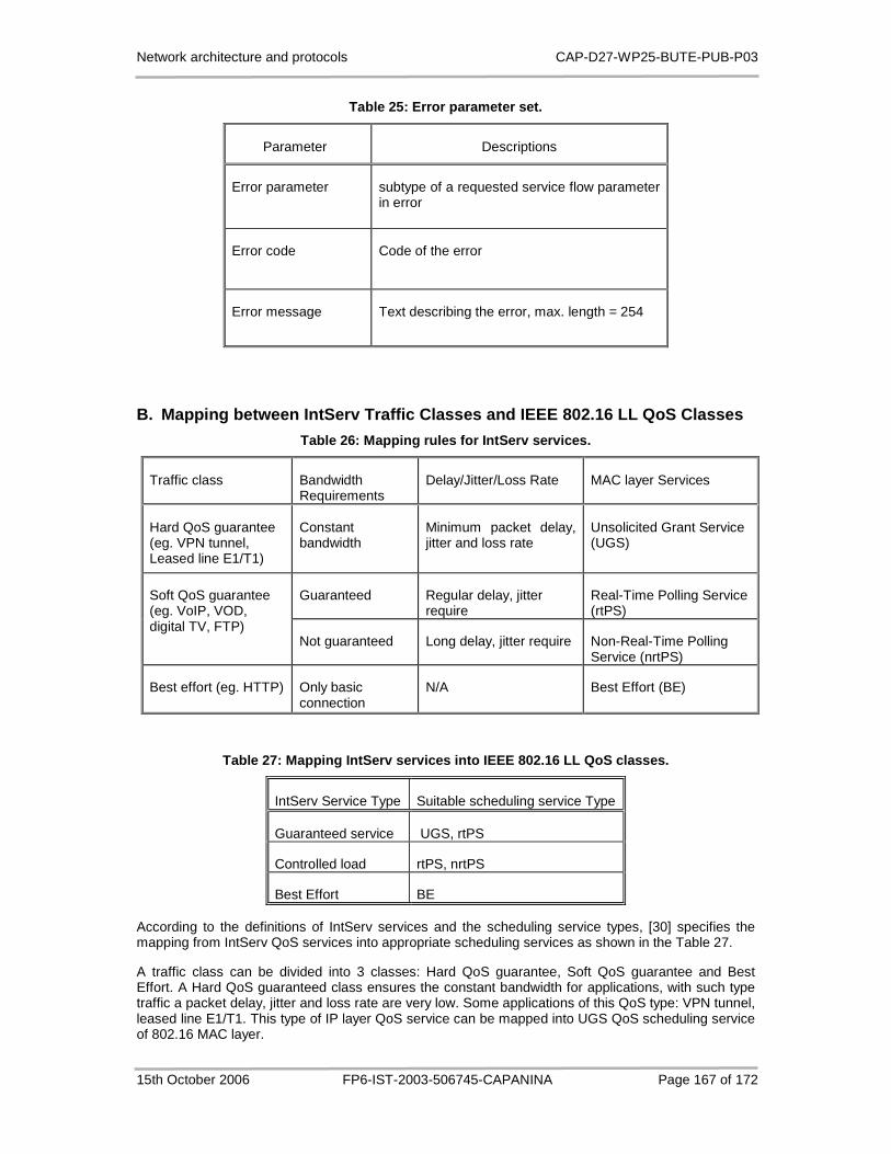
Network architecture and protocols CAP-D27-WP25-BUTE-PUB-P03
15th October 2006 FP6-IST-2003-506745-CAPANINA Page 167 of 172
Table 25: Error parameter set.
Parameter Descriptions
Error parameter subtype of a requested service flow parameter in error
Error code Code of the error
Error message Text describing the error, max. length = 254
B. Mapping between IntServ Traffic Classes and IEEE 802.16 LL QoS Classes
Table 26: Mapping rules for IntServ services.
Traffic class Bandwidth Requirements
Delay/Jitter/Loss Rate MAC layer Services
Hard QoS guarantee (eg. VPN tunnel, Leased line E1/T1)
Constant bandwidth
Minimum packet delay, jitter and loss rate
Unsolicited Grant Service (UGS)
Guaranteed Regular delay, jitter require
Real-Time Polling Service (rtPS)
Soft QoS guarantee (eg. VoIP, VOD, digital TV, FTP)
Not guaranteed Long delay, jitter require Non-Real-Time Polling Service (nrtPS)
Best effort (eg. HTTP) Only basic connection
N/A Best Effort (BE)
Table 27: Mapping IntServ services into IEEE 802.16 LL QoS classes.
IntServ Service Type Suitable scheduling service Type
Guaranteed service UGS, rtPS
Controlled load rtPS, nrtPS
Best Effort BE
According to the definitions of IntServ services and the scheduling service types, [30] specifies the mapping from IntServ QoS services into appropriate scheduling services as shown in the Table 27.
A traffic class can be divided into 3 classes: Hard QoS guarantee, Soft QoS guarantee and Best Effort. A Hard QoS guaranteed class ensures the constant bandwidth for applications, with such type traffic a packet delay, jitter and loss rate are very low. Some applications of this QoS type: VPN tunnel, leased line E1/T1. This type of IP layer QoS service can be mapped into UGS QoS scheduling service of 802.16 MAC layer.

Network architecture and protocols CAP-D27-WP25-BUTE-PUB-P03
15th October 2006 FP6-IST-2003-506745-CAPANINA Page 168 of 172
A Soft QoS guarantee class can be divided to 2 subclasses: bandwidth guaranteed with regular delay and low jitter, e.g. VoIP, VOD (Voice on Demand), Digital TV…. The other subclass is no bandwidth guaranteed with long delay and jitter, as FTP application. Based on nature of 802.16 MAC layer scheduling services, bandwidth guaranteed subclass can be mapped into Real-Time Polling Service QoS class, and the no bandwidth guaranteed subclass can be mapped into Non Real-Time Polling Service Class.
And finally, the Best Effort traffic from IP layer can be mapped into Best Effort traffic class of MAC layer trivially [30].
C. Mapping between DiffServ Traffic Classes and IEE E 802.16 LL QoS Classes
In RFC 795, the IP Type of Service has the following fields:
0 1 2 3 4 5 6 7
PRECEDENCE D T R 0 0
Bits 0-2: Precedence.
Bit 3: 0 = Normal Delay, 1 = Low Delay.
Bits 4: 0 = Normal Throughput, 1 = High Throughput.
Bits 5: 0 = Normal Reliability, 1 = High Reliability.
Bits 6-7: Reserved for Future Use.
Where D-T-R trio means:
111 - Network Control 110 - Internetwork Control
101 - CRITIC/ECP 100 - Flash Override
011 – Flash 010 - Immediate
001 – Priority 000 – Routine
ToS Octet
P2
P1
P0
T3
T2
T1
T0
0
DS Octet
DS5
DS4
DS3
DS2
DS1
DS0
ECN1
ECN0
Class Selector Drop Precedence
Figure 92: Differentiated Services Code Point
For DiffServ services, DSCP code is deployed for classification. As shown in Figure 92, the first 3 bits are for class selector, the middle 3 bits are for drop priority. There are three definitions of per-hop behaviour (PHB) to specify the forwarding treatment for the packet. Expedited forwarding (EF) is intended to provide a building block for low delay, low jitter and low loss services by ensuring that the EF aggregate is served at a certain configured rate. Assured Forwarding (AF) PHB group is to provider different levels of forwarding assurances for IP packets. Four AF classes are defined; where
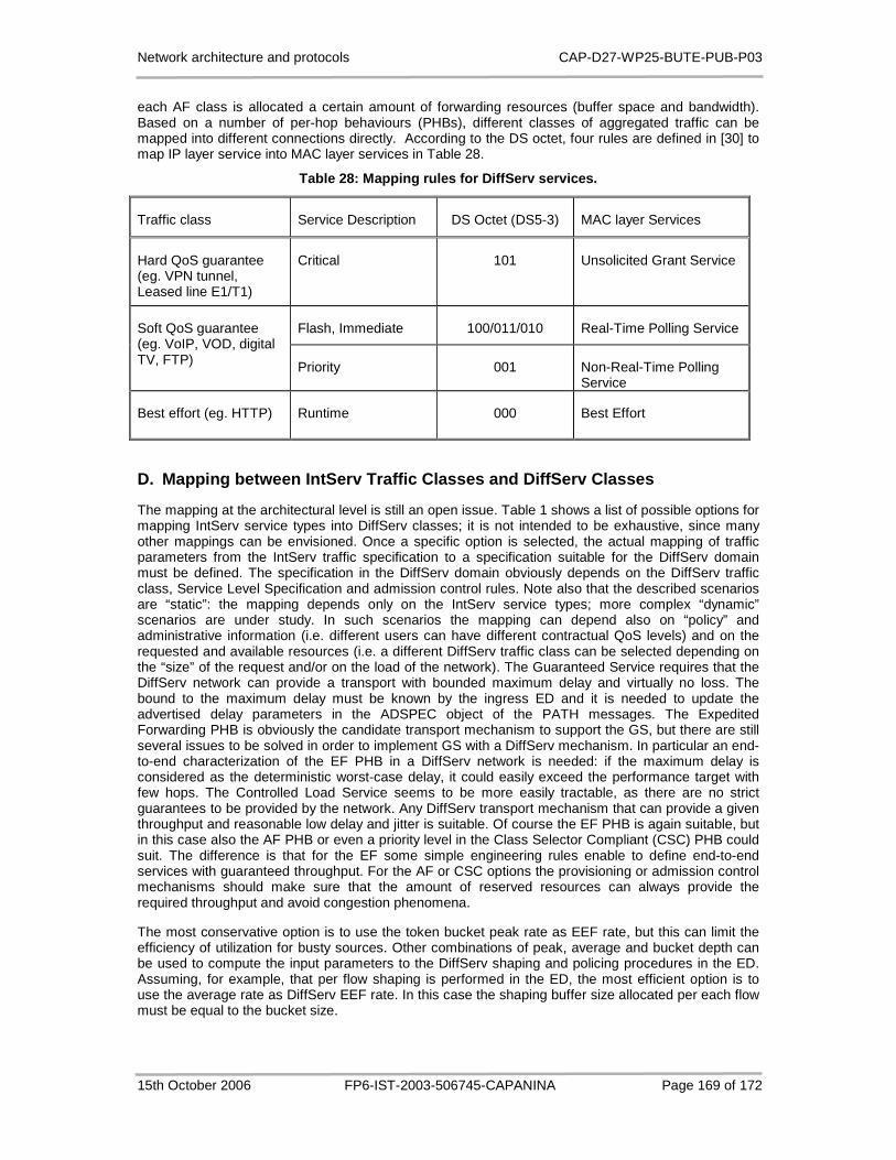
Network architecture and protocols CAP-D27-WP25-BUTE-PUB-P03
15th October 2006 FP6-IST-2003-506745-CAPANINA Page 169 of 172
each AF class is allocated a certain amount of forwarding resources (buffer space and bandwidth). Based on a number of per-hop behaviours (PHBs), different classes of aggregated traffic can be mapped into different connections directly. According to the DS octet, four rules are defined in [30] to map IP layer service into MAC layer services in Table 28.
Table 28: Mapping rules for DiffServ services.
D. Mapping between IntServ Traffic Classes and Diff Serv Classes
The mapping at the architectural level is still an open issue. Table 1 shows a list of possible options for mapping IntServ service types into DiffServ classes; it is not intended to be exhaustive, since many other mappings can be envisioned. Once a specific option is selected, the actual mapping of traffic parameters from the IntServ traffic specification to a specification suitable for the DiffServ domain must be defined. The specification in the DiffServ domain obviously depends on the DiffServ traffic class, Service Level Specification and admission control rules. Note also that the described scenarios are “static”: the mapping depends only on the IntServ service types; more complex “dynamic” scenarios are under study. In such scenarios the mapping can depend also on “policy” and administrative information (i.e. different users can have different contractual QoS levels) and on the requested and available resources (i.e. a different DiffServ traffic class can be selected depending on the “size” of the request and/or on the load of the network). The Guaranteed Service requires that the DiffServ network can provide a transport with bounded maximum delay and virtually no loss. The bound to the maximum delay must be known by the ingress ED and it is needed to update the advertised delay parameters in the ADSPEC object of the PATH messages. The Expedited Forwarding PHB is obviously the candidate transport mechanism to support the GS, but there are still several issues to be solved in order to implement GS with a DiffServ mechanism. In particular an end-to-end characterization of the EF PHB in a DiffServ network is needed: if the maximum delay is considered as the deterministic worst-case delay, it could easily exceed the performance target with few hops. The Controlled Load Service seems to be more easily tractable, as there are no strict guarantees to be provided by the network. Any DiffServ transport mechanism that can provide a given throughput and reasonable low delay and jitter is suitable. Of course the EF PHB is again suitable, but in this case also the AF PHB or even a priority level in the Class Selector Compliant (CSC) PHB could suit. The difference is that for the EF some simple engineering rules enable to define end-to-end services with guaranteed throughput. For the AF or CSC options the provisioning or admission control mechanisms should make sure that the amount of reserved resources can always provide the required throughput and avoid congestion phenomena.
The most conservative option is to use the token bucket peak rate as EEF rate, but this can limit the efficiency of utilization for busty sources. Other combinations of peak, average and bucket depth can be used to compute the input parameters to the DiffServ shaping and policing procedures in the ED. Assuming, for example, that per flow shaping is performed in the ED, the most efficient option is to use the average rate as DiffServ EEF rate. In this case the shaping buffer size allocated per each flow must be equal to the bucket size.
Traffic class Service Description DS Octet (DS5-3) MAC layer Services
Hard QoS guarantee (eg. VPN tunnel, Leased line E1/T1)
Critical 101 Unsolicited Grant Service
Flash, Immediate 100/011/010 Real-Time Polling Service Soft QoS guarantee (eg. VoIP, VOD, digital TV, FTP) Priority 001 Non-Real-Time Polling
Service
Best effort (eg. HTTP) Runtime 000 Best Effort

Network architecture and protocols CAP-D27-WP25-BUTE-PUB-P03
15th October 2006 FP6-IST-2003-506745-CAPANINA Page 170 of 172
Some previous works (RFC 2998),[35],[36],[37] has proposed how to map IntServ service to appropriate DiffServ service. In order to combine the superior scalability of DiffServ model with IntServ superior QoS support capabilities, the ISSL (Integrated Service to over Specific Link Layers) working group of the IETF proposed the interoperation between these two models (RFC 2998). The defined approach combines the IntServ model features- Capability to establish and maintain resources reservations through network elements – with scalability provided by the DiffServ model. The IntServ model is applicable in the network core to take advantage of its scalability. The boundary routers between these two networks are responsible for mapping the IntServ flows into the DiffServ classes. These functions include the choice of the most appropriate PHB to support the flow and the use of admission control (AC) and policing functions on the flows at the entrance of the DiffServ region.
In the border between the IntServ and DiffServ regions, the network elements must perform the mapping of the requested IntServ service into a DiffServ class of service. The DiffServ class must be selected in a way to support the type of IntServ service requested for application. Taking into account the already defined IntServ services (GS and CLS), the PHBs currently available in DiffServ (AF and EF) and, considering the characteristics of each service and PHB respectively, the choice of mapping between service CL and PHB AF, and between service GS and PHB EF is evident.
The mapping of the CL service into the AF PHBs must be based on the burst time of the CL flow [35]. This way, the flows are grouped in the AF class which provides the better guarantee that the packet average queue delay does not exceed the burst time of the flow. The mapping can be static or dynamic: static mapping is defined by the administrator of the network; the dynamic mapping is driven according to the characteristics of the existing traffic in the network. In [36], A. Pereira et al. proposed a mapping mechanism between the Controlled-Load service of the IntServ model and the Assured Forwarding PHB group of the DiffServ model. The proposed mapping mechanism included a dynamic Admission Control module that takes into account the state of the DiffServ network. In their approach, the decision of mapping and admission of a new IntServ flow in the DiffServ region is based on the behaviour of previous flows to the same IntServ destination network. This behaviour is evaluated by of delay and losses suffered by the flows in the DiffServ region. The strategy adopted is based on the monitoring of flows at both the ingress and the egress of DiffServ domains to evaluate if the QoS of the mapped flows was degraded or not. In the case where no degradation occurs new flows can be admitted and mapped. On the other hand, if the QoS characteristics have been degraded, no more flows can be admitted into the DiffServ network ingress and the number of active flows must be reduced. By monitoring the flows at the egress of the DiffServ domain, the QoS characteristics are evaluated on the basis of the packet loss, since the queuing delay is less representative and more difficult to treat with passive measurements due to its wide variability and to the difficulty of clock synchronization. The proposed strategy for mapping IntServ flows into DiffServ classes is based on two mechanisms located in the network elements at the boundary of the DiffServ region: the Mapper and the Meter. In the edge router at the ingress of DiffServ domain, the Mapper maps CL flows into the AF class that better supports the IntServ service. This mechanism acts on the basis of the information supplied by the Meter mechanism located in edge router at the egress of the DiffServ domain. The Meter mechanism interacts with the modules of the IntServ model, and with the meter module of the DiffServ model (which is responsible for accounting, for each flow, the packets in agreement with the attributed DSCP). Whenever a RSVP message of reserve removal occurs, the collected information is inserted in a new object called DIFFSERV_STATUS and is sent to the ingress edge router of the DiffServ domain such that it can be taken into account for the next flow mapping.
E. Channel Model for Performance Evaluation of APS
In our model, the wireless channel quality is characterized by the received signal-to-noise ratio (SNR). The received SNR range is partitioned into intervals, and each interval is assigned to one burst profile, which consist of a modulation and a channel coding technique used to tell which data rate is used to transfer data in downlink (or uplink) between BS and each SSs. An SS measures the received signal level sent by the BS and decides which burst profile is the best for its downlink transmission. The burst profile change request then can be sent to the BS on the up-link. To simulate wireless channel, we use the model presented in [26] by H.S. Wang et al.

Network architecture and protocols CAP-D27-WP25-BUTE-PUB-P03
15th October 2006 FP6-IST-2003-506745-CAPANINA Page 171 of 172
In most previous works, the two-state Markov channel was used to model wireless channel. In a two-state Markov channel known as the Gilbert–Elliot channel, each state corresponds to a specific channel quality which is either noiseless or totally noisy. But this model is not adequate in our case where the channel quality varies drastically. Therefore a finite-state Markov model [26] is good model to simulate our wireless channel as Figure 93.
Figure 93: Rayleigh fading channel with K-state Mar kov model.
Let }1 ,...,1 ,0{ −= KS denotes a finite set of states. By partitioning the range of the received SNR into a finite number of intervals, Finite State Markov Chain (FSMC) models can be constructed for Rayleigh fading channels [26]. The members of set S correspond to those partitions. Now let
,...1 ,0 },{ =nSn be a stationary Markov process. Since a stationary Markov process has the property
of time-invariant transition probabilities, the transition probability jip , in Figure 93 is independent of
the time index n and can be written as:
}1,...,1,0{,
,...1 ,0 ),|Pr( 1,
−∈
===≡ +
Kji
nsSsSp injnji (E.1)
The transition is only happened between adjacent states, so
}.1 ,...,1 ,0{, ,1 ,0, −∈>−= Kjijip ji (E.2)
Otherwise, the Rayleigh fading channel is assumed slow enough that the received SNR remains at a certain level for the time duration of a channel symbol.
In a typical multi-path propagation environment, the received signal envelope has Rayleigh distribution. With additive Gaussian noise, the received instantaneous SNR γ is distributed exponentially with probability density function (PDF)
0 ),exp(1
)(00
≥−= γγγ
γγp (E.3)
Where 0γ is the average SNR ( ][0 kAΕ=γ ). An FSMC model can be build to represent the time-
varying behaviour of the Rayleigh fading channel. The received SNR is partitioned into finite number of intervals. Let ∞=<<<= KAAAA ...0 210 be the thresholds of the received SNR. Then the
channel is in state k if the received SNR is between kA and 1+kA . A received packet is said to be in
channel state 1 ..., 1, ,0 , K-ksk = , if the SNR values in the packet varies in the range [ )1, +kk AA .
Let tR be a symbol rate and fixed. The transition probability 1, +kkp can be approximated by the ratio
of the expected level crossing )( 1+kAN from the state ks to 1+ks divided by average symbols per
second, where )(AN is the expected number of times per second the received SNR passes
downward across the threshold A is the level crossing function given by

Network architecture and protocols CAP-D27-WP25-BUTE-PUB-P03
15th October 2006 FP6-IST-2003-506745-CAPANINA Page 172 of 172
)exp(2
)(00 γγ
π Af
AAN d −= (E.4)
Where the maximum Doppler frequency df is defined asλν=df , where ν is the mobile’s speed, and
λ is the wavelength.
Similarly, the transition probability 1, −kkp can be approximated by the ratio of the expected level
crossing )( kAN from the state ks to 1−ks divided by average symbols per second.
In this FSMC model, transitions are just allowed from given state to its two adjacent states only. So the transition probabilities
jip , can be determined using the following equations:
1,...,2,1 ,)(
2,...,1,0 ,)(
1,
11,
−=≈
−=≈
−
++
KkR
ANp
KkR
ANp
t
kkk
t
kkk
(E.5)
These Euations (E.2) and (E.5) can be used to calculate the transition probability matrix of wireless channel of our simulation. The steady state probabilities can be easily calculated as in a usual birth-dead process.