network management card 3 installation guide
TRANSCRIPT

Installation ManualUPS Network Management Card 3
AP9640, AP9641, AP9643990-9996F-001Publication Date: August 2020
Schneider Electric IT Corporation Legal DisclaimerThe information presented in this manual is not warranted by the Schneider Electric IT Corporation to be authoritative, error free, or complete. This publication is not meant to be a substitute for a detailed operational and site specific development plan. Therefore, Schneider Electric IT Corporation assumes no liability for damages, violations of codes, improper installation, system failures, or any other problems that could arise based on the use of this Publication.
The information contained in this Publication is provided as is and has been prepared solely for the purpose of evaluating data center design and construction. This Publication has been compiled in good faith by Schneider Electric IT Corporation. However, no representation is made or warranty given, either express or implied, as to the completeness or accuracy of the information this Publication contains.
IN NO EVENT SHALL SCHNEIDER ELECTRIC IT CORPORATION, OR ANY PARENT, AFFILIATE OR SUBSIDIARY COMPANY OF SCHNEIDER ELECTRIC IT CORPORATION OR THEIR RESPECTIVE OFFICERS, DIRECTORS, OR EMPLOYEES BE LIABLE FOR ANY DIRECT, INDIRECT, CONSEQUENTIAL, PUNITIVE, SPECIAL, OR INCIDENTAL DAMAGES (INCLUDING, WITHOUT LIMITATION, DAMAGES FOR LOSS OF BUSINESS, CONTRACT, REVENUE, DATA, INFORMATION, OR BUSINESS INTERRUPTION) RESULTING FROM, ARISING OUT, OR IN CONNECTION WITH THE USE OF, OR INABILITY TO USE THIS PUBLICATION OR THE CONTENT, EVEN IF SCHNEIDER ELECTRIC IT CORPORATION HAS BEEN EXPRESSLY ADVISED OF THE POSSIBILITY OF SUCH DAMAGES. SCHNEIDER ELECTRIC IT CORPORATION RESERVES THE RIGHT TO MAKE CHANGES OR UPDATES WITH RESPECT TO OR IN THE CONTENT OF THE PUBLICATION OR THE FORMAT THEREOF AT ANY TIME WITHOUT NOTICE.
Copyright, intellectual, and all other proprietary rights in the content (including but not limited to software, audio, video, text, and photographs) rests with Schneider Electric IT Corporation or its licensors. All rights in the content not expressly granted herein are reserved. No rights of any kind are licensed or assigned or shall otherwise pass to persons accessing this information.
This Publication shall not be for resale in whole or in part.
This manual is available in English on the APC website (www.apc.com).
Dieses Handbuch ist in Deutsch auf der APC webseite (www.apc.com) verfügbar.
Данное руководство на русском языке доступно на сайте APC (www.apc.com )本マニュアルの日本語版は APCウェブサイト(www.apc.com) からダウンロードできます。在 APC 公司的网站上 (www.apc.com) 有本手册的中文版。
Contents
Installation Manuali
Important Safety Information . . . . . . . . . . . . . . . . . . . . . . . . . . . . 1Safety Information for the Network Management Card 3 . . . 2
Preliminary Information . . . . . . . . . . . . . . . . . . . . . . . . . . . . . . . . . 3Features . . . . . . . . . . . . . . . . . . . . . . . . . . . . . . . . . . . . . . . 3Supported Devices . . . . . . . . . . . . . . . . . . . . . . . . . . . . . . . 4Related documents . . . . . . . . . . . . . . . . . . . . . . . . . . . . . . . 5Inventory . . . . . . . . . . . . . . . . . . . . . . . . . . . . . . . . . . . . . . . 5Disclaimer . . . . . . . . . . . . . . . . . . . . . . . . . . . . . . . . . . . . . . 5Changing Web UI Language . . . . . . . . . . . . . . . . . . . . . . . . 6
Installation in a UPS. . . . . . . . . . . . . . . . . . . . . . . . . . . . . . . . . . . . 7How to install the card for different UPS models . . . . . . . . . 7Step 1: Install the Network Management Card . . . . . . . . . . 7Step 2: Configure the Network Management Card . . . . . . . 8
Expansion/Triple Chassis Installation . . . . . . . . . . . . . . . . . . . . . 9When to use an Expansion Chassis . . . . . . . . . . . . . . . . . . 9Step 1: Disconnect the chassis from all power . . . . . . . . . . 9Step 2: Install the Network Management Card . . . . . . . . . . 9
Quick Configuration. . . . . . . . . . . . . . . . . . . . . . . . . . . . . . . . . . . 11Overview . . . . . . . . . . . . . . . . . . . . . . . . . . . . . . . . . . . . . . 11TCP/IP configuration methods . . . . . . . . . . . . . . . . . . . . . . 11UPS User Interface Display . . . . . . . . . . . . . . . . . . . . . . . . 12Local access to the command line interface . . . . . . . . . . . 12Remote access to the command line interface . . . . . . . . . 13Command line interface . . . . . . . . . . . . . . . . . . . . . . . . . . . 14Device IP Configuration Wizard . . . . . . . . . . . . . . . . . . . . . 15DHCP and BOOTP configuration . . . . . . . . . . . . . . . . . . . . 15.INI file utility . . . . . . . . . . . . . . . . . . . . . . . . . . . . . . . . . . . 17
How to Reset after a Lost Password . . . . . . . . . . . . . . . . . . . . . 18
iiInstallation Manual
How to Access a Configured Network Management Card . . . . 19Overview . . . . . . . . . . . . . . . . . . . . . . . . . . . . . . . . . . . . . . 19Web interface . . . . . . . . . . . . . . . . . . . . . . . . . . . . . . . . . . 19Command Line Interface access - SSH and Telnet Access 20Simple Network Management Protocol (SNMP) . . . . . . . . 20SCP and FTP . . . . . . . . . . . . . . . . . . . . . . . . . . . . . . . . . . 21Manage the security of your system . . . . . . . . . . . . . . . . . 21
How to Install Multiple Management Cards . . . . . . . . . . . . . . . . 22Overview . . . . . . . . . . . . . . . . . . . . . . . . . . . . . . . . . . . . . . 22Before you start . . . . . . . . . . . . . . . . . . . . . . . . . . . . . . . . . 22Two models of expansion chassis . . . . . . . . . . . . . . . . . . . 23Installing cards in an expansion chassis . . . . . . . . . . . . . . 23Installing cards in an expansion chassis set up serially . . . 23Installing cards in a Symmetra UPS . . . . . . . . . . . . . . . . . 24
Specifications AP9640, AP9641 . . . . . . . . . . . . . . . . . . . . . . . . . 26
Specifications AP9643 . . . . . . . . . . . . . . . . . . . . . . . . . . . . . . . . . 27
1 Installation Manual
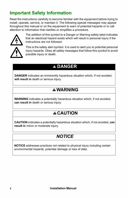
Important Safety InformationRead the instructions carefully to become familiar with the equipment before trying to install, operate, service, or maintain it. The following special messages may appear throughout this manual or on the equipment to warn of potential hazards or to call attention to information that clarifies or simplifies a procedure.
The addition of this symbol to a Danger or Warning safety label indicates that an electrical hazard exists which will result in personal injury if the instructions are not followed.
This is the safety alert symbol. It is used to alert you to potential personal injury hazards. Obey all safety messages that follow this symbol to avoid possible injury or death.
DANGER
DANGER indicates an imminently hazardous situation which, if not avoided, will result in death or serious injury.
WARNING
WARNING indicates a potentially hazardous situation which, if not avoided, can result in death or serious injury.
CAUTION
CAUTION indicates a potentially hazardous situation which, if not avoided, can result in minor or moderate injury.
NOTICE
NOTICE addresses practices not related to physical injury including certain environmental hazards, potential damage or loss of data.
Installation Manual 2
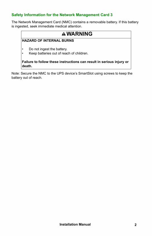
Safety Information for the Network Management Card 3
The Network Management Card (NMC) contains a removable battery. If this battery is ingested, seek immediate medical attention.
Note: Secure the NMC to the UPS device’s SmartSlot using screws to keep the battery out of reach.
WARNINGHAZARD OF INTERNAL BURNS
• Do not ingest the battery.• Keep batteries out of reach of children.
Failure to follow these instructions can result in serious injury or death.
3 Installation Manual
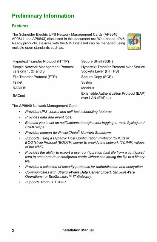
Preliminary InformationFeatures
The AP9640 Network Management Card:• Provides UPS control and self-test scheduling features.• Provides data and event logs.• Enables you to set up notifications through event logging, e-mail, Syslog and
SNMP traps.• Provides support for PowerChute® Network Shutdown.• Supports using a Dynamic Host Configuration Protocol (DHCP) or
BOOTstrap Protocol (BOOTP) server to provide the network (TCP/IP) values of the NMC.
• Provides the ability to export a user configuration (.ini) file from a configured card to one or more unconfigured cards without converting the file to a binary file.
• Provides a selection of security protocols for authentication and encryption.• Communicates with StruxureWare Data Center Expert, StruxureWare
Operations, or EcoStruxure™ IT Gateway.• Supports Modbus TCP/IP.
The Schneider Electric UPS Network Management Cards (AP9640, AP9641 and AP9643) discussed in this document are Web-based, IPv6 Ready products. Devices with the NMC installed can be managed using multiple open standards such as:
Hypertext Transfer Protocol (HTTP) Secure SHell (SSH)Simple Network Management Protocol versions 1, 2c and 3
Hypertext Transfer Protocol over Secure Sockets Layer (HTTPS)
File Transfer Protocol (FTP) Secure Copy (SCP)Telnet SyslogRADIUS Modbus
BACnet Extensible Authentication Protocol (EAP) over LAN (EAPoL)
Installation Manual 4
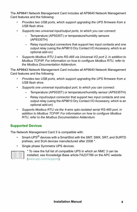
The AP9641 Network Management Card includes all AP9640 Network Management Card features and the following:
• Provides two USB ports, which support upgrading the UPS firmware from a USB flash drive.
• Supports two universal input/output ports, to which you can connect:– Temperature (AP9335T) or temperature/humidity sensors
(AP9335TH)– Relay input/output connectors that support two input contacts and one
output relay (using the AP9810 Dry Contact I/O Accessory, which is an optional add-on)
• Supports Modbus RTU 2-wire RS-485 via Universal I/O port 2, in addition to Modbus TCP/IP. For information on how to configure Modbus RTU, refer to the Modbus Documentation Addendum.
The AP9643 Network Management Card includes all AP9640 Network Management Card features and the following:
• Provides two USB ports, which support upgrading the UPS firmware from a USB flash drive.
• Supports one universal input/output port, to which you can connect:– Temperature (AP9335T) or temperature/humidity sensor (AP9335TH)– Relay input/output connector that support two input contacts and one
output relay (using the AP9810 Dry Contact I/O Accessory, which is an optional add-on)
• Supports Modbus RTU via the 4-wire opto-isolated serial RS-485 port, in addition to Modbus TCP/IP. For information on how to configure Modbus RTU, refer to the Modbus Documentation Addendum.
Supported Devices
The Network Management Card 3 is compatible with: • Smart-UPS® devices with a SmartSlot with the SMT, SMX, SRT, and SURTD
prefixes, and SUA devices manufactured after 2008 *.• Single phase Symmetra UPS devices.
* To view the full list of compatible UPS in which an NMC 3 can be installed, see Knowledge Base article FA237786 on the APC website (www.apc.com/support).
5 Installation Manual
Related documents
The following documentation is available on the APC website (https://www.apc.com/upsnmc):
• UPS Network Management Card 3 User Guide• UPS Network Management Card 3 Command Line Interface Guide• UPS Network Management Card 3 Modbus Documentation Addendum
(AP9641, AP9643 only)• UPS Network Management Card 3 Modbus Register Maps• UPS Network Management Card 3 BACnet Application Maps• Security Handbook• PowerNet® Management Information Base (MIB) Reference Guide• Declaration of Conformity
InventoryThe Network Management Card package includes the following items:
• This Installation Manual• UPS Network Management Card 3• Micro-USB configuration cable (part number 960-0603)• Temperature sensor (AP9335T)—AP9641 and AP9643 Network
Management Cards only• Network Management Card quality assurance test slip• Warranty registration form
The quality assurance test slip contains the MAC address that you may need when performing the procedures in “UPS User Interface Display” on page 12. You can also find the MAC address on the bottom of your NMC.
Disclaimer
Schneider Electric is not responsible for damage sustained during reshipment of this product.
The Network Management Card 3 (NMC 3) is sensitive to static electricity. When handling the NMC, touch only the end plate while using one or more of these electrostatic-discharge devices (ESDs): wrist straps, heel straps, toe straps, or conductive shoes.
Please recycleThe shipping materials are recyclable. Save them for later use, or dispose of them appropriately.
Installation Manual 6
Management products, including the NMC, contain removable, lithium coin-cell batteries. When discarding these batteries, you must follow local rules for recycling.
Changing Web UI Language
You can change the language the NMC Web interface is displayed in via the log in screen. See “Changing Web UI Language” in the User Guide (www.apc.com/us/en/download/document/SPD_CCON-AYCEFJ_EN) for more information.
7 Installation Manual
Installation in a UPSHow to install the card for different UPS models
To view the full list of compatible UPS in which an NMC can be installed, see Knowledge Base article FA237786 on the APC website (www.apc.com/support).In a Symmetra UPS that uses more than one management product, you must install the management products in the correct order for them to operate properly.
See “How to Install Multiple Management Cards” on page 22.
Step 1: Install the Network Management Card
You do not need to turn off power to install the NMC in a supported Smart-UPS or Symmetra UPS. If you want to turn off your UPS before installing the Network Management Card, see the Knowledge Base article FA156132 on the APC website (www.apc.com/support).
The NMC is sensitive to static electricity. When handling the NMC, touch only the end plate while using one or more of these electrostatic-discharge devices (ESDs): wrist straps, heel straps, toe straps, or conductive shoes.
The Network Management Card (NMC) contains a removable battery. If this battery is ingested, seek immediate medical attention.
Note: Secure the NMC to the UPS device’s SmartSlot using screws to keep the battery out of reach.
WARNINGHAZARD OF INTERNAL BURNS
• Do not ingest the battery.• Keep batteries out of reach of children.
Failure to follow these instructions can result in serious injury or death.
Installation Manual 8
For the location of the UPS card slot, see the UPS documentation.
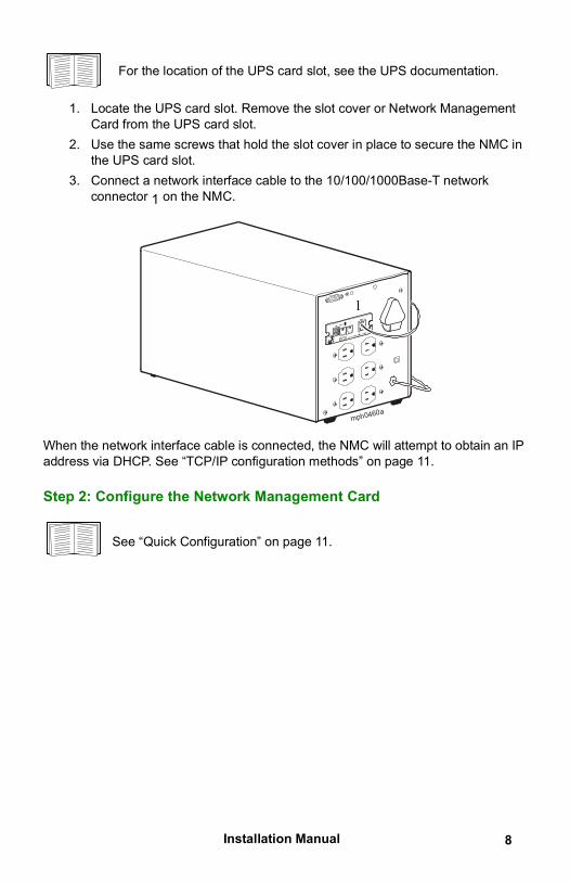
1. Locate the UPS card slot. Remove the slot cover or Network ManagementCard from the UPS card slot.
2. Use the same screws that hold the slot cover in place to secure the NMC inthe UPS card slot.
3. Connect a network interface cable to the 10/100/1000Base-T networkconnector 1 on the NMC.
When the network interface cable is connected, the NMC will attempt to obtain an IP address via DHCP. See “TCP/IP configuration methods” on page 11.
Step 2: Configure the Network Management Card
See “Quick Configuration” on page 11.
mph0460a
1
9 Installation Manual
Expansion/Triple Chassis InstallationWhen to use an Expansion Chassis
Use an Expansion Chassis or a Triple Expansion Chassis if the UPS has no card slot available.
The Single (AP9600) or Triple Expansion Chassis (AP9604) are only compatible with UPS models that have a DB9 serial port. They are compatible with following UPS models only: SURT, SURTA, Symmetra® LX, SU, SUA, and SUM.When you install the UPS Network Management Card 3 (NMC 3) in the chassis, the NMC communicates with the UPS through the cable connection between the chassis and the UPS.
Step 1: Disconnect the chassis from all power
Make sure that the Expansion Chassis or Triple Expansion Chassis is disconnected from any power source:
1. Disconnect the chassis cable from the UPS.2. If the chassis uses an AC adapter (AP9505), disconnect that adapter from
the chassis.
Step 2: Install the Network Management Card
If the UPS uses multiple management products, you must install them in the correct order for them to operate properly.
See “How to Install Multiple Management Cards” on page 22.
The UPS Network Management Card (NMC) is sensitive to static electricity. When handling the NMC, touch only the end plate while using one or more of these electrostatic-discharge devices (ESDs): wrist straps, heel straps, toe straps, or conductive shoes.

Installation Manual 10
The Network Management Card (NMC) contains a removable battery. If this battery is ingested, seek immediate medical attention.
Note: Secure the NMC to the UPS device’s SmartSlot using screws to keep the battery out of reach.
If a cable is connected to the serial port at the UPS or chassis, stop the APC service that uses that serial connection, and disconnect the cable.
1. If you are installing a chassis, connect the chassis to the UPS serial port.
2. Use the same screws that hold the expansion slot cover in place to secure the NMC in the chassis slot.
3. Connect a network interface cable to the 10/100/1000Base-T network connector on the front panel of the NMC.
4. If you are using the AC Adapter (AP9505), connect the adapter to the chassis. Then connect the adapter to an independent AC input so that the NMC can continue to operate if the UPS is turned off or not operating.
5. If you disconnected a cable in step 1, reconnect that cable to the serial port at the chassis, and restart the associated APC service.
6. See “Quick Configuration” on page 11.
WARNINGHAZARD OF INTERNAL BURNS
• Do not ingest the battery.• Keep batteries out of reach of children.
Failure to follow these instructions can result in serious injury or death.
11 Installation Manual
Quick ConfigurationOverview
Disregard the procedures described in this chapter if you have StruxureWare Data Center Expert as part of your system. See the documentation for your StruxureWare device for more information.
You must configure the following TCP/IP settings before the UPS Network Management Card (NMC) can operate on a network:
• IP address of the NMC• Subnet mask• Default gateway
If a default gateway is unavailable, use the IP address of a computer that is located on the same subnet as the NMC and that is usually running. The NMC uses the default gateway to test the network when traffic is very light. Do not use the loopback address (127.0.0.1) as the default gateway address for the NMC. It disables the card and requires you to reset TCP/IP settings to their defaults using a local serial login.
See “Watchdog Features” in the NMC User Guide (www.apc.com/us/en/download/document/SPD_CCON-AYCEFJ_EN) for more information about the watchdog role of the default gateway.
TCP/IP configuration methods
Use one of the following methods to define the TCP/IP settings needed by the Network Management Card for IPv4:
• “UPS User Interface Display” on page 12• Networked computer:
– “Local access to the command line interface” on page 12– “Remote access to the command line interface” on page 13
• “Device IP Configuration Wizard” on page 15• “DHCP and BOOTP configuration” on page 15• “How to Reset after a Lost Password” on page 18
Installation Manual 12
UPS User Interface Display
Configuration of the NMC IP address though the UPS user interface display is not available for all UPS models.
For Smart-UPS model UPS with the prefix SMT, SMX, or SRT, the NMC IP address can be configured at the user interface of the UPS:
1. If you plan to manually assign the network settings, contact your system administrator to obtain a valid IP address, subnet mask, and default gateway for the Network Management Card.
2. At the user interface display, press the Home icon.3. Select Configuration > Network.4. At the prompt, enter the user password for your UPS (apc, by default), then
select NMC Settings.5. For the Network Management Card you are configuring, select Configure
NMC Settings.6. In the Network settings mode drop-down list, select the network
configuration option for your system: Manual, BootP, DHCP, or DHCP & BootP.
– If you select Manual, enter the IP address, subnet mask, and default gateway you obtained in step 1.
– If you select BootP, DHCP, or DHCP & BootP, a DHCP or BOOTP server will assign the IP address, subnet mask, and default gateway for the Network Management Card.
7. Press Apply to save your changes.
Local access to the command line interface
For local access, use a computer that connects to the Network Management Card through the serial port to access the command line interface:
1. Select a serial port at the computer, and disable any service that uses that port.
2. Connect the provided micro-USB configuration cable (part number 960-0603) from the selected port on the computer to the configuration port at the NMC.
3. Run a terminal program (e.g. 3rd party terminal emulator programs like HyperTerminal, PuTTy, or Tera Term) and configure the selected port for 9600 bps, 8 data bits, no parity, 1 stop bit, and no flow control. Save the changes.
4. Press ENTER, repeatedly if necessary, to display the User Name prompt.5. Use apc for the user name and password.
13 Installation Manual
NOTE: The user name will be “apc” at first log for the Super User account. You will be prompted to enter a new password after you log in.
See “Command line interface” on page 14 to finish the configuration.
NOTE: A driver is required to connect to the NMC console via Windows 7. The driver can be downloaded from the AP9640/AP9641 product pageon the APC website (www.apc.com/upsnmc), located in the Software /Firmware section. No driver is required for Windows 10.1.When you connect the NMC via the micro-USB cable, a device called“NMC3-CDC” is discovered in “Other Devices”.2.Right-click on this device and select “Update Driver Software...”3.Select the “Browse my computer for driver software” option andnavigate to the download location of the driver (usb_cdc_ser.inf).4.Accept the unsigned driver security message.Windows will now recognize the NMC and assign a COM port to the device.If the micro-USB cable is left connected to the NMC, the NMC will wait 90 seconds at each boot up to access the Boot Monitor. To avoid this 90 second boot delay, disconnect the micro-USB cable if local access to the CLI is not required.
Remote access to the command line interface
From any computer on the same network as the Network Management Card, you can use ARP and Ping to assign an IP address to the Network Management Card, and then use Secure Shell (SSH) to access its command line interface and configure the other TCP/IP settings.
After the Network Management Card has its IP address configured, you can use SSH, without first using ARP and Ping, to access that Network Management Card.
1. Use the MAC address of the Network Management Card in the ARPcommand to define the IP address.NOTE: Look for the MAC address on the bottom of the NetworkManagement Card or on the Quality Assurance slip included in the package.For example, to define 156.205.14.141 as the IP address of a NetworkManagement Card with 00 c0 b7 63 9f 67 as its MAC address, use one ofthe following commands:
– Windows command format:
arp -s 156.205.14.141 00-c0-b7-63-9f-67
– LINUX command format:
Installation Manual 14
arp -s 156.205.14.141 00:c0:b7:63:9f:67
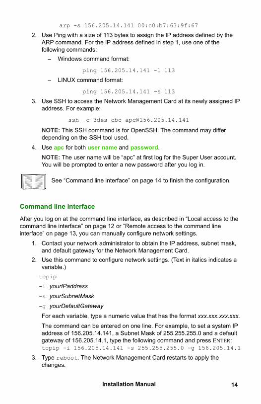
2. Use Ping with a size of 113 bytes to assign the IP address defined by theARP command. For the IP address defined in step 1, use one of thefollowing commands:
– Windows command format:
ping 156.205.14.141 -l 113
– LINUX command format:
ping 156.205.14.141 -s 113
3. Use SSH to access the Network Management Card at its newly assigned IPaddress. For example:
ssh -c 3des-cbc [email protected]
NOTE: This SSH command is for OpenSSH. The command may differ depending on the SSH tool used.
4. Use apc for both user name and password.NOTE: The user name will be “apc” at first log for the Super User account.You will be prompted to enter a new password after you log in.
See “Command line interface” on page 14 to finish the configuration.
Command line interface
After you log on at the command line interface, as described in “Local access to the command line interface” on page 12 or “Remote access to the command line interface” on page 13, you can manually configure network settings.
1. Contact your network administrator to obtain the IP address, subnet mask,and default gateway for the Network Management Card.
2. Use this command to configure network settings. (Text in italics indicates avariable.)tcpip
-i yourIPaddress
-s yourSubnetMask
-g yourDefaultGateway
For each variable, type a numeric value that has the format xxx.xxx.xxx.xxx.The command can be entered on one line. For example, to set a system IPaddress of 156.205.14.141, a Subnet Mask of 255.255.255.0 and a defaultgateway of 156.205.14.1, type the following command and press ENTER:tcpip -i 156.205.14.141 -s 255.255.255.0 -g 156.205.14.1
3. Type reboot. The Network Management Card restarts to apply thechanges.
15 Installation Manual
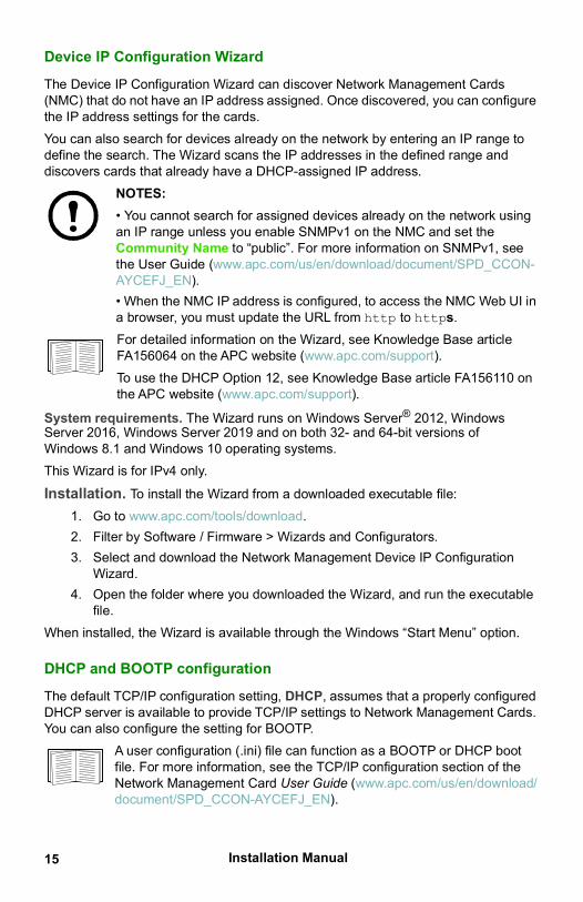
Device IP Configuration Wizard
The Device IP Configuration Wizard can discover Network Management Cards (NMC) that do not have an IP address assigned. Once discovered, you can configure the IP address settings for the cards.You can also search for devices already on the network by entering an IP range to define the search. The Wizard scans the IP addresses in the defined range and discovers cards that already have a DHCP-assigned IP address.
NOTES:• You cannot search for assigned devices already on the network usingan IP range unless you enable SNMPv1 on the NMC and set theCommunity Name to “public”. For more information on SNMPv1, seethe User Guide (www.apc.com/us/en/download/document/SPD_CCON-AYCEFJ_EN).• When the NMC IP address is configured, to access the NMC Web UI ina browser, you must update the URL from http to https.For detailed information on the Wizard, see Knowledge Base article FA156064 on the APC website (www.apc.com/support).To use the DHCP Option 12, see Knowledge Base article FA156110 on the APC website (www.apc.com/support).
System requirements. The Wizard runs on Windows Server® 2012, Windows Server 2016, Windows Server 2019 and on both 32- and 64-bit versions of Windows 8.1 and Windows 10 operating systems.This Wizard is for IPv4 only.
Installation. To install the Wizard from a downloaded executable file:1. Go to www.apc.com/tools/download.2. Filter by Software / Firmware > Wizards and Configurators.3. Select and download the Network Management Device IP Configuration
Wizard.4. Open the folder where you downloaded the Wizard, and run the executable
file.When installed, the Wizard is available through the Windows “Start Menu” option.
DHCP and BOOTP configuration
The default TCP/IP configuration setting, DHCP, assumes that a properly configured DHCP server is available to provide TCP/IP settings to Network Management Cards. You can also configure the setting for BOOTP.
A user configuration (.ini) file can function as a BOOTP or DHCP boot file. For more information, see the TCP/IP configuration section of the Network Management Card User Guide (www.apc.com/us/en/download/document/SPD_CCON-AYCEFJ_EN).
Installation Manual 16
If neither of these servers is available, see “UPS User Interface Display” on page 12, “Local access to the command line interface” on page 12, “Remote access to the command line interface” on page 13 or “UPS User Interface Display” on page 18 to configure the needed TCP/IP settings.
BOOTP. For the Network Management Card to use a BOOTP server to configure its TCP/IP settings, it must find a properly configured RFC951-compliant BOOTP server.In the BOOTPTAB file of the BOOTP server, enter the Network Management Card’s MAC address, IP address, subnet mask, and default gateway, and, optionally, a bootup file name. Look for the MAC address on the bottom of the Network Management Card or on the Quality Assurance slip included in the package.When the Network Management Card reboots, the BOOTP server provides it with the TCP/IP settings.
• If you specified a bootup file name, the Network Management Card attempts to transfer that file from the BOOTP server using TFTP or FTP. The Network Management Card assumes all settings specified in the bootup file.
• If you did not specify a bootup file name, you can configure the other settings of the Network Management Card remotely through its Web interface or command line interface; the user name and password are both apc, by default.
To create a bootup file, see your BOOTP server documentation.
17 Installation Manual
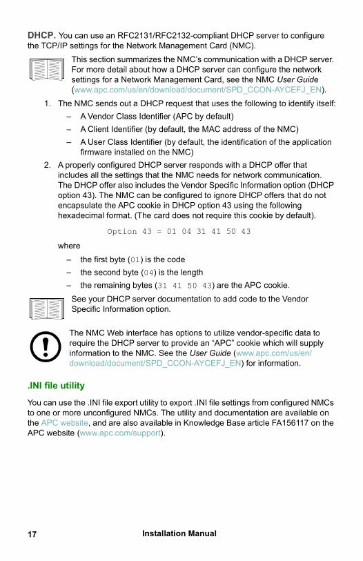
DHCP. You can use an RFC2131/RFC2132-compliant DHCP server to configure the TCP/IP settings for the Network Management Card (NMC).
This section summarizes the NMC’s communication with a DHCP server. For more detail about how a DHCP server can configure the network settings for a Network Management Card, see the NMC User Guide (www.apc.com/us/en/download/document/SPD_CCON-AYCEFJ_EN).
1. The NMC sends out a DHCP request that uses the following to identify itself:– A Vendor Class Identifier (APC by default)– A Client Identifier (by default, the MAC address of the NMC)– A User Class Identifier (by default, the identification of the application
firmware installed on the NMC)2. A properly configured DHCP server responds with a DHCP offer that
includes all the settings that the NMC needs for network communication.The DHCP offer also includes the Vendor Specific Information option (DHCPoption 43). The NMC can be configured to ignore DHCP offers that do notencapsulate the APC cookie in DHCP option 43 using the followinghexadecimal format. (The card does not require this cookie by default).
Option 43 = 01 04 31 41 50 43
where – the first byte (01) is the code– the second byte (04) is the length– the remaining bytes (31 41 50 43) are the APC cookie.
See your DHCP server documentation to add code to the VendorSpecific Information option.
The NMC Web interface has options to utilize vendor-specific data to require the DHCP server to provide an “APC” cookie which will supply information to the NMC. See the User Guide (www.apc.com/us/en/download/document/SPD_CCON-AYCEFJ_EN) for information.
.INI file utility
You can use the .INI file export utility to export .INI file settings from configured NMCs to one or more unconfigured NMCs. The utility and documentation are available on the APC website, and are also available in Knowledge Base article FA156117 on the APC website (www.apc.com/support).
Installation Manual 18
How to Reset after a Lost PasswordNOTE: Resetting your NMC will reset the card to its default configuration.
If you forget your password, you must use the Reset button on the NMC to wipe all configuration, including the password. Hold down the Reset button for 20-25 seconds, ensuring the Status LED is pulsing green during this time. When the Status LED changes to amber or orange, release the Reset button to allow the NMC to complete its reboot process.After the NMC reboots, you must re-configure your NMC. See “Quick Configuration” on page 11.
It is recommended you export the .ini file after configuring your NMC to prevent loss of data in the event of a lost password. See “Retrieving and Exporting the .ini File” in the NMC User Guide (www.apc.com/us/en/download/document/SPD_CCON-AYCEFJ_EN) for more information.
Installation Manual19
How to Access a Configured Network Management CardOverview
After the UPS Network Management Card (NMC) is running on your network, you can use the interfaces summarized here: Web interface, Telnet, SSH, SNMP, FTP, and SCP. For more information about the interfaces, see the User Guide (www.apc.com/us/en/download/document/SPD_CCON-AYCEFJ_EN).
Web interface
The Network Management Card 3 Web interface is compatible with:• Windows® operating systems:
– Microsoft® Internet Explorer® (IE) 11 or higher, with compatibility viewturned on.
– The latest release of Microsoft® Edge®
• All operating systems:– The latest releases of Mozilla® Firefox® or Google® Chrome®
Other commonly available browsers may work but have not been fully tested by APC by Schneider Electric. You can use either of the following protocols when you use the Web interface:
• By default, only HTTPS is enabled. The HTTPS protocol (enabled bydefault), which provides extra security through Secure Socket Layer (SSL);encrypts user names, passwords, and data being transmitted; andauthenticates Network Management Cards by means of digital certificates.
• The HTTP protocol, which provides authentication by user name andpassword but no encryption.NOTE: HTTP is disabled by default. The first log in to the Web UI must beusing the HTTPS protocol.
To access the Web interface and configure the security of your device on the network:
1. Address the Network Management Card by its IP address (or its DNS name,if a DNS name is configured).
2. Enter the user name and password.3. To enable or disable HTTPS, or enable HTTP, use the NMC Web interface.
See the Security Handbook (www.apc.com/us/en/download/document/SPD_CCON-BDYD7K_EN) for more information on selecting and configuring network security.
20Installation Manual
Command Line Interface access - SSH and Telnet Access
You can access the command line interface through Secure SHell (SSH) or Telnet, depending on which is enabled. To enable these access methods, use the NMC Web interface. By default, only SSH is enabled.
SSH for high-security access. If you use the high security of SSL for the Web interface, use Secure SHell (SSH) for access to the command line interface. SSH encrypts user names, passwords, and transmitted data. The interface, user accounts, and user access rights are the same whether you access the command line interface through SSH or Telnet, but to use SSH, you must first configure SSH and have an SSH client program installed on your computer.
See the User Guide (www.apc.com/us/en/download/document/SPD_CCON-AYCEFJ_EN) for more information on configuring and using SSH.
To access the command line interface using SSH, at a command prompt enter:
ssh -c 3des-cbc <username>@<IP address>
NOTE: This SSH command is for OpenSSH. The command may differ depending on the SSH tool used.
Telnet for basic access. By default, Telnet is disabled. Telnet provides the basic security of authentication by user name and password, but not the high-security benefits of encryption. To use Telnet to access the command line interface of the Network Management Card from any computer on the same subnet:
1. At a command prompt, use the following command line, and press ENTER:telnet address
As address, use the Network Management Card’s IP address (or DNSname, if configured).
2. Enter the user name and password.
Simple Network Management Protocol (SNMP)
SNMPv1, SNMPv2c, and SNMPv3 are all disabled by default. You must configure community names in the Web UI before you can enable any version of SNMP.To enable or disable SNMP access, you must be an Administrator. Use the NMC Web interface or Command Line interface to set it up.
SNMPv1 only. After you add the PowerNet® MIB to a standard SNMP MIB browser, you can use that browser to access the Network Management Card. All user names, passwords, and community names for SNMP are transferred over the network as plain text.
Installation Manual21
Use of SNMPv2c is supported by the SNMPv1 options.
SNMPv3 only. For SNMP GETs, SETs, and trap receivers, SNMPv3 uses a system of user profiles to identify users. An SNMPv3 user must have a user profile assigned in the MIB software program to perform GETs and SETs, browse the MIB, and receive traps.
To use SNMPv3, you must have a MIB program that supports SNMPv3. The Network Management Card supports SHA or MD5 authentication and AES or DES encryption.
SNMPv1 and SNMPv3. To use StruxureWare Data Center Expert and EcoStruxure IT to manage the Network Management Card on the public network of an StruxureWare/EcoStruxure IT system, you must have SNMPv1 enabled in the unit interface. Read access allows StruxureWare Data Center Expert and EcoStruxure IT to receive traps from the Network Management Card. Write access is required while you set StruxureWare Data Center Expert and EcoStruxure IT as a trap receiver.
SCP and FTP
You can use SCP or FTP to transfer downloaded firmware to the Network Management Card, or to access a copy of the Network Management Card’s event or data logs. NOTE: By default, only SCP is enabled. You can use SCP once you have used SSH or HTTPS to create a user password.To use StruxureWare Data Center Expert to manage the UPS, you must have the FTP Server option enabled in the Network Management Card interface.To enable or disable FTP server access, you must be an Administrator. Use the NMC Web interface or Command Line interface to set it up.
To transfer firmware, see the User Guide (www.apc.com/us/en/download/document/SPD_CCON-AYCEFJ_EN).The SCP interface is enabled when SSH is enabled, as they are part of the same protocol suite. See the User Guide for more information on configuring and using SSH.
To retrieve a copy of the event or data log, see the User Guide (www.apc.com/us/en/download/document/SPD_CCON-AYCEFJ_EN).
Manage the security of your systemFor detailed information on enhancing the security of your system after installation and initial configuration, see the Security Handbook (www.apc.com/us/en/download/document/SPD_CCON-BDYD7K_EN).
22Installation Manual
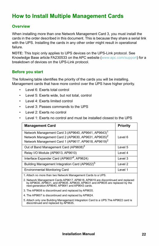
How to Install Multiple Management CardsOverview
When installing more than one Network Management Card 3, you must install the cards in the order described in this document. This is because they share a serial link with the UPS. Installing the cards in any other order might result in operational failure.NOTE: This topic only applies to UPS devices on the UPS-Link protocol. See Knowledge Base article FA230533 on the APC website (www.apc.com/support) for a breakdown of devices on the UPS-Link protocol.
Before you start
The following table identifies the priority of the cards you will be installing. Management cards that have more control over the UPS have higher priority.
• Level 6: Exerts total control• Level 5: Exerts wide, but not total, control• Level 4: Exerts limited control• Level 3: Passes commands to the UPS• Level 2: Exerts no control• Level 1: Exerts no control and must be installed closest to the UPS
Management Card Priority
Network Management Card 3 (AP9640, AP9641, AP9643)1
Network Management Card 2 (AP9630, AP9631, AP9635)2 Network Management Card 1 (AP9617, AP9618, AP9619)2
Level 6
Out of Band Management Card (AP9608)3 Level 5
Relay I/O Module (AP9613, AP9610) Level 4
Interface Expander Card (AP96074, AP9624) Level 3
Building Management Integration Card (AP9622)5 Level 2
Environmental Monitoring Card Level 11. Attach no more than two Network Management Cards to a UPS.
2. Network Management Cards AP9617, AP9618, AP9619 are discontinued and replaced by AP9630, AP9631, and AP9635. AP9630, AP9631 and AP9635 are replaced by the next-generation AP9640, AP9641 and AP9643 cards.
3. The AP9608 is discontinued and replaced by AP9635.
4. The AP9607 is discontinued and replaced by AP9624.
5. Attach only one Building Management Integration Card to a UPS.The AP9622 card isdiscontinued and replaced by AP9635.
Installation Manual23
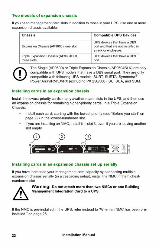
Two models of expansion chassis
If you need management card slots in addition to those in your UPS, use one or more expansion chassis available.
The Single (AP9600) or Triple Expansion Chassis (AP9604BLK) are only compatible with UPS models that have a DB9 serial port. They are only compatible with following UPS models: SURT, SURTA, Symmetra® Power Array/RM/LX/PX (excluding PX 250/500), SU, SUA, and SUM.
Installing cards in an expansion chassis
Install the lowest-priority cards in any available card slots in the UPS, and then use an expansion chassis for remaining higher-priority cards. In a Triple Expansion Chassis:
• Install each card, starting with the lowest priority (see “Before you start” onpage 22) in the lowest-numbered slot.
• If you are installing an NMC, install it in slot 3, even if you are leaving anotherslot empty.
Installing cards in an expansion chassis set up serially
If you have increased your management card capacity by connecting multiple expansion chassis serially (in a cascading setup), install the NMC in the highest-numbered slot
Warning: Do not attach more than two NMCs or one Building Management Integration Card to a UPS.
If the NMC is pre-installed in the UPS, refer instead to “When an NMC has been pre-installed.” on page 25.
Chassis Compatible UPS Devices
Expansion Chassis (AP9600), one slot UPS devices that have a DB9 port and that are not installed in a rack or enclosure.
Triple Expansion Chassis (AP9604BLK), three slots
UPS devices that have a DB9 port.
21
Status
PowerMonitoring Port
To UPS24 VDC– +–
3Probes
1 2Sensor Zones
AP9612TH Environmental Monitoring Card
1 2 3 4GND Management Port
Status
AP9608 Out-of-Band Management Card
1 2 3
S m a rt S lot A 963 Network Management Card 2P 1
USB
Config
U niv ers al I /O U niv ers al I /O
Reset
10/100
Network
mph
046
1
24Installation Manual
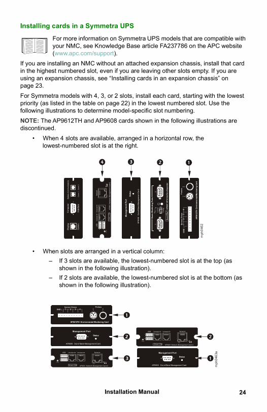
Installing cards in a Symmetra UPS
For more information on Symmetra UPS models that are compatible with your NMC, see Knowledge Base article FA237786 on the APC website (www.apc.com/support).
If you are installing an NMC without an attached expansion chassis, install that card in the highest numbered slot, even if you are leaving other slots empty. If you are using an expansion chassis, see “Installing cards in an expansion chassis” on page 23. For Symmetra models with 4, 3, or 2 slots, install each card, starting with the lowest priority (as listed in the table on page 22) in the lowest numbered slot. Use the following illustrations to determine model-specific slot numbering. NOTE: The AP9612TH and AP9608 cards shown in the following illustrations are discontinued.
• When 4 slots are available, arranged in a horizontal row, thelowest-numbered slot is at the right.
• When slots are arranged in a vertical column:– If 3 slots are available, the lowest-numbered slot is at the top (as
shown in the following illustration).– If 2 slots are available, the lowest-numbered slot is at the bottom (as
shown in the following illustration).
Com
pute
rB
atte
ry C
omm
unic
atio
ns
Com
m. 1
Com
m. 2
Inte
rfac
e
Dis
play
Com
m.
1 2
3 4
Co
nfig
21
0 1
TM
AP
9607
UP
S In
terf
ace
Exp
ande
r
Ba
sic
Mo
nit
ori
ng
Po
rts
q
q
Ma
nag
em
en
t P
ort
Sta
tus
AP
9608
O
ut-
of-B
and
Man
agem
ent C
ard
Pro
be
s1
2
Se
nso
r Z
on
es
AP
9612
TH
En
viro
nm
en
tal M
on
ito
rin
g C
ard
1
2
3
4G
ND
Smart Slot
A96
3 N
etw
ork
Ma
nag
em
ent
Ca
rd 2
P1
US
B
Co
nfig
Univers
al I
/OU
nive
rsal
I/O
Res
et
10
/10
0Net
wor
k
mph
046
2
Management Port
Status
AP9608 Out-of-Band Management Card
Probes1 2
Sensor Zones
AP9612TH Environmental Monitoring Card
1 2 3 4GND
Smart Slot A 963 N etw ork M anagement Card 2P 1
USB
C onfig
Universal I/O Universal I/O
R eset
10/100
Network
mph
046
3a
Management Port
Status
AP9608 Out-of-Band Management Card
Smart Slot A 963 N etw ork M anagement Card 2P 1
USB
C onfig
Universal I/O Universal I/O
R eset
10/100
Network
Installation Manual25
When an NMC has been pre-installed. For Symmetra UPS models that are shipped with a Network Management Card already installed (such as Symmetra LX models), the UPS itself may have only one remaining card slot available. Referring to the table on page 22, install the lowest priority card in the UPS and use one or more expansion chassis for any other cards, as described beginning on page 23.
26Installation Manual
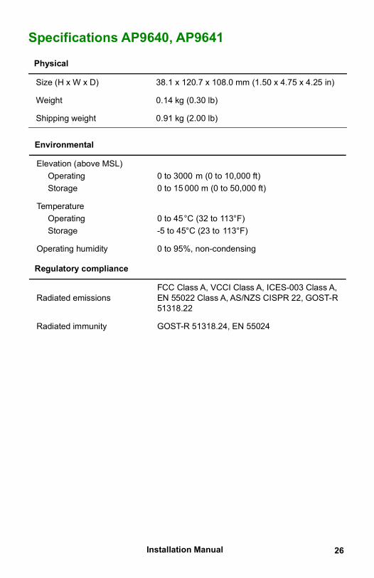
Specifications AP9640, AP9641
Physical
Size (H x W x D) 38.1 x 120.7 x 108.0 mm (1.50 x 4.75 x 4.25 in)
Weight 0.14 kg (0.30 lb)
Shipping weight 0.91 kg (2.00 lb)
Environmental
Elevation (above MSL)OperatingStorage
0 to 3000 m (0 to 10,000 ft)0 to 15 000 m (0 to 50,000 ft)
TemperatureOperatingStorage
0 to 45°C (32 to 113°F)-5 to 45°C (23 to 113°F)
Operating humidity 0 to 95%, non-condensing
Regulatory compliance
Radiated emissionsFCC Class A, VCCI Class A, ICES-003 Class A, EN 55022 Class A, AS/NZS CISPR 22, GOST-R 51318.22
Radiated immunity GOST-R 51318.24, EN 55024

Installation Manual27
Specifications AP9643
Physical
Size (H x W x D) 38.1 x 120.7 x 108.0 mm (1.50 x 4.75 x 4.25 in)
Weight 0.14 kg (0.30 lb)
Shipping weight 0.91 kg (2.00 lb)
Environmental
Elevation (above MSL)OperatingStorage
0 to 3000 m (0 to 10,000 ft)0 to 15 000 m (0 to 50,000 ft)
TemperatureOperatingStorage
-5 to 45°C (32 to 113°F)-15 to 65°C (5 to 149°F)
Operating humidity 0 to 95%, non-condensing
Regulatory compliance
Radiated emissionsFCC Class A, VCCI Class A, ICES-003 Class A, EN 55022 Class A, AS/NZS CISPR 22, GOST-R 51318.22
Radiated immunity GOST-R 51318.24, EN 55024
cryptlib copyright Digital Data Security New Zealand Ltd 1998.
Copyright © 1990, 1993, 1994 The Regents of the University of California. All rights reserved.
This code is derived from software contributed to Berkeley by Mike Olson.
Redistribution and use in source and binary forms, with or without modification, are permitted provided that the following conditions are met:
1. Redistributions of source code must retain the above copyright notice, thislist of conditions and the following disclaimer.
2. Redistributions in binary form must reproduce the above copyright notice,this list of conditions and the following disclaimer in the documentationand/or other materials provided with the distribution.
3. All advertising materials mentioning features or use of this software mustdisplay the following acknowledgment:
This product includes software developed by the University of California, Berkeley and its contributors.
4. Neither the name of the University nor the names of its contributors may beused to endorse or promote products derived from this software withoutspecific prior written permission.
THIS SOFTWARE IS PROVIDED BY THE REGENTS AND CONTRIBUTORS “AS IS” AND ANY EXPRESS OR IMPLIED WARRANTIES, INCLUDING, BUT NOT LIMITED TO, THE IMPLIED WARRANTIES OF MERCHANTABILITY AND FITNESS FOR A PARTICULAR PURPOSE ARE DISCLAIMED. IN NO EVENT SHALL THE REGENTS OR CONTRIBUTORS BE LIABLE FOR ANY DIRECT, INDIRECT, INCIDENTAL, SPECIAL, EXEMPLARY, OR CONSEQUENTIAL DAMAGES (INCLUDING, BUT NOT LIMITED TO, PROCUREMENT OF SUBSTITUTE GOODS OR SERVICES; LOSS OF USE, DATA, OR PROFITS; OR BUSINESS INTERRUPTION) HOWEVER CAUSED AND ON ANY THEORY OF LIABILITY, WHETHER IN CONTRACT, STRICT LIABILITY, OR TORT (INCLUDING NEGLIGENCE OR OTHERWISE) ARISING IN ANY WAY OUT OF THE USE OF THIS SOFTWARE, EVEN IF ADVISED OF THE POSSIBILITY OF SUCH DAMAGE.
Radio Frequency InterferenceChanges or modifications to this unit not expressly approved by the party responsible for compliance could void the user’s authority to operate this equipment.
USA—FCC
This equipment has been tested and found to comply with the limits for a Class A digital device, pursuant to part 15 of the FCC Rules. These limits are designed to provide reasonable protection against harmful interference when the equipment is operated in a commercial environment. This equipment generates, uses, and can radiate radio frequency energy and, if not installed and used in accordance with this user manual, may cause harmful interference to radio communications. Operation of this equipment in a residential area is likely to cause harmful interference. The user will bear sole responsibility for correcting such interference.
Canada—ICES
This Class A digital apparatus complies with Canadian ICES-003.
Cet appareil numérique de la classe A est conforme à la norme NMB-003 du Canada.
Japan—VCCIこの装置は、クラスA機器です。この装置を住宅環境で使用すると電波妨
害を引き起こすことがあります。この場合には使用者が適切な対策を講ずるよう要求されることがあります。
VCCI-A
Taiwan—BSMI警告使用者 :這是甲類的資訊產品 , 在居住的環境中使用時 ,可能會造成射頻干擾 , 在這種情況下 ,使用者會被要求採取某些適當的對策。
Australia and New Zealand
Attention: This is a Class A product. In a domestic environment this product may cause radio interference in which case the user may be required to take adequate measures.
European Union
This product is in conformity with the protection requirements of EU Council Directive 2004/108/EC on the approximation of the laws of the Member States relating to electromagnetic compatibility. APC cannot accept responsibility for any failure to satisfy the protection requirements resulting from an unapproved modification of the product.
This product has been tested and found to comply with the limits for Class A Information Technology Equipment according to CISPR 22/European Standard EN 55022. The limits for Class A equipment were derived for commercial and industrial environments to provide a reasonable protection against interference with licensed communication equipment.
Attention: This is a Class A product. In a domestic environment this product may cause radio interference in which case the user may be required to take adequate measures.

APC by Schneider Electric Worldwide Customer Support
Customer support for this or any other product is available at no charge in any of the following ways:
• Visit the APC Web site to access documents in the APC Knowledge Baseand to submit customer support requests.– www.apc.com (Corporate Headquarters)
Connect to localized APC Web sites for specific countries, each ofwhich provides customer support information.
– www.apc.com/support/Global support searching APC Knowledge Base and using e-support.
• Contact the APC Customer Support Center by telephone or e-mail.– Local, country-specific centers: go to www.apc.com/support/contact for
contact information.
For information on how to obtain local customer support, contact the representative or other distributors from whom you purchased your product.
© 2020 Schneider Electric. All Rights Reserved. Schneider Electric, APC, Network Management Card, and Smart-UPS are trademarks and the property of Schneider Electric SE, its subsidiaries and affiliated companies. All other trademarks are property of their respective
owners.
8/2020990-9996F-001